UNCLASSIFIED AD NUMBER AD829742 NEW LIMITATION CHANGE TO Approved for public release, distribution unlimited FROM Distribution authorized to U.S. Gov't. agencies and their contractors; Critical Technology; 01 FEB 1968. Other requests shall be referred to Air Force Materials Laboratory, Attn: MAAM, Wright-Patterson, AFB, OH 45433. AUTHORITY AFML, USAF ltr, 12 Jan 1972 THIS PAGE IS UNCLASSIFIED

Welcome message from author
This document is posted to help you gain knowledge. Please leave a comment to let me know what you think about it! Share it to your friends and learn new things together.
Transcript

UNCLASSIFIED
AD NUMBER
AD829742
NEW LIMITATION CHANGE
TOApproved for public release, distributionunlimited
FROMDistribution authorized to U.S. Gov't.agencies and their contractors; CriticalTechnology; 01 FEB 1968. Other requestsshall be referred to Air Force MaterialsLaboratory, Attn: MAAM, Wright-Patterson,AFB, OH 45433.
AUTHORITY
AFML, USAF ltr, 12 Jan 1972
THIS PAGE IS UNCLASSIFIED

NICKEL BASE ALLOYS0q ALLOY 718
Into docuiont Ic ".,bjct to spocin~l nyport controlS wi v.1
learjiv.1i.Lal to foroigni govertiaert:. Ora tDg nt~m~ido Only with pti or aproval. of c.
PROCESSES AND PROPERTIESHANDBOOK D D C
I~~ I I .ALI

The Defense Metals Information Center was established at Battelle Memorial Institute atthe requeat of the Office of the Director of Defense Research and Engineering to provide Govern-ment contractors and their suppliers technical assistance and information on titanium, beryllium,magnesium, aluminum, high-strength steels, refractory metals, high-strength alloys for high-temperature service, and corrosion- and oxidation-resistant coatings. Its functions, under thedirection of the Office of the Director of Defense Research and Engineering, are as follows:
1. To collect, store, and disseminate technical information on the currentstatus of research and development of the above materials.
2. To supplement established Service activities in providing technical ad-visc•y services to producers, melters, and fabricators of the abovematerials, and to designers and fabricators of military equipment con-taining these materials.
3. To assist the Government agencies and their contractors in developingtechnical data required for preparation of specifications for the abovematerials.
4. On assignment, to conduct surveys, or laboratory risearch investiga-tions, mainly of a short-range nature, as required, to ascertain causesof troubles encountered by fabricators, or to fill minor gaps in estab-lished research programs.
.__ _ Contract No. AF 33(615)-3408
MMl171 ILCT1U 03
SRoge.....Director.,,. ....... .o .o• o,.... . o°.o.¢....
WT.'IAIL N/'N
Notices
When Government drawings, specifications, or other data are used for any purpose other thad inconnection with a definitely related Government procurement operation, the United States Governmentthereby incurs no responsibility nor any obligation wha:soever; and the fact that the Government mayhave formulated, furnished, or in any way supplied the said drawings, specifications, or other data, isnot to be regarded by implication or otherwise as in any manner licensing the holder or any other personor corporation, or conveying any rights or permission to manufacture, use, or sell any patented inven-tion that may in any way be related thereto.
Qualified requesters may obtain copies of this report from the Defense Documentation Center (DDC),Cameron Station, Bldg. 5, S010 Duke Street, Alexwndria, Virginia, 22314. The distribution of this re-port Is limited because the report contains technology identifiable with items on the strategic embargolists excluded from export or re-export under U. S. Export Control Act of 1949 (63 STAT. 7), as amended(50 U.S.C. App. 2020.2031), as implemented by AFR 400-10.
Copies of this report should not be returned to the Research and Technology Division, Wright-Patterson Air Force Base, Ohio, unless return is required by security considerations, contractual ob-ligations, or notice on a specific document.

NICKEL BASE ALLOYS
ALLOY 718
H. J. Wagner, R. S. Burns, T. E. Carroll, and R. C. Simon*
ABSTRACT
The DTC Handbook on Alloy 7i% is 3 compilation of available dataand information covering the metallurgy, manufacturing, applications, andmechanical properties of this nickel-base heat-resistant alloy. Much of the 
textual matter has been condensed from reports and literature received fromb-th the producers and the users of this alloy and covers subjects such asmelting, forming, welding, metallography, and others of interest to the user.Mechanical properties are presented for each of the product forms and con-ditions in which this alloy is used and both original a,.nd digested data areincluded for tensile, fatigue, creep-rupture, and other properties.
"Mr. Wagner is Chief of the Specialty Alloys Division; Messrs. BurnN andCarroll are Information Snecialists, and Mr. Simon is an Informationknalvst, in the Information Operations Division. Battelle ColumbusLaboratories, Columbus, Ohio.
Si
11

TA6LE OF CONTENTS
AB¢hACT ................................ i IV. MECIIAYICAL PROPERTIES ................ IV-l
INTRODUCTION .......................... iii All Forms ....................... IV-lDesign Properties .......... IV-I
M. HETALII7............................II Sheet and Plate ................. IV-bTensile Properties ......... IV-6
eltng . .Notched Tensile Properties. IV-iSCasting ........................ 1-1 Fatigue Properties ......... IV-17Hetalworkir...................... I-I Creep-rupture Properties... IV-37
Metallotraph! ................... 1-3 Sheet (cold-rolled and aged) .... IV-41Corrosion.........................1-4 rensile Properties ......... IV-41Stress Corroson .................. 1-4 Notched Tensile Properties. IV-35
Physical Metallurgy ............ 1 4 Fatigue Properties ......... IV-47Creep-rupture Propetties... IV-48
II. ,ANUFACTURING PROCESSES .............. HI-I Bars ard Forgings ............... IV-49Tensile Properties ......... IV-49
Machining ....................... 11I- Impact Properties .......... IV-S9
Forming......................... I1-I Fatigue Properties .......... IV-60
General .................... II-1 Creep-rupture Properties... IV-64
Dimpling ................... . I-I Castings ......................... IV-69
heat Treating ................... 11-3 Tensile Properties......... . . V-69
Cleaning ........ ............... 11-4 Compressive Properties ..... IV-72Coating Impact Properties .......... IV-73Joining ............................. Fracture-toughness Properties IV-74
TIG Keldir.g ................ II-5 Thernal-fatigue Properties. IV-75
Electron Bean Wejuing ...... 11-7 Creep-rupture Properties... IV-76
Resistance Welding ......... 11-8Brazing ........... ........ 11-5 V . APPENCIX ............................. V-I
Adhesive Bonding ........... 1I-10CSurface Finishing............... 11-10 Specifications ..................
Chemical Composition ............. V-3
IIl. APPLICATION FACTORS .................. Ill-i" References ....................... . -7List of Symbols ................. V_-Il
Uses ............................ 111-1 Data Bas5 ...................... .... V-12Constant-Life Diagrams (fatgue) V-12
-J

I NTRODUCTI ON
Alloy 718 is a wrought nickel-ba-e ailoy which was initiallyintended for Uasc up to about 1300 F. it differs from the 1500 to 1800 Fnickel alloys in that (1) columbium is substituted for much of thealuminum and tilanium and (2) 19 percent iron is substi~uted for most ofthe molybdenum and all of the cobalt. The effect of these differences isto iedice the high-temperature strength with a corresponding increase inw,-ldabi litv.
A variety of heat treatments and compositional variations havebeen used to achieve specific optimum properties such as:
1. Short-time high-temperature tensile strength2. Stress-rupture strength3. Notch tensile strength4. Fatigue strength5. i'eldabi lity.
In adCition, it was discovered that, when properly processed,Alloy 718 has aseful cryogenic properties down to -423 F.
Variations in heat treatment and composition and other physical-metallurgy details of Allov 718 are fully discussed in DMlC Report 217 byWagner and Hall.
Since DMIC issued Report 217, a considerable quantity of propertydata on Alloy 718 have been extracted and tabulated. The primary purpose ofthis !handbook is to make these data available for general dissemination. Muchof the informaticn on physical metallurgy was taken from Report 217, andcondensed and repackaged to fit the Handbook format.
i ii N

I
I. METALLURGY
Melting
CostingMetalworkingMetal logra phy
CorrosionStress CorrosionPhysical Metallurgy

~~40"
MELTINGFNickel-base alloys are more difficult to
Alloy 718 is usually vacuum melted. Pro- forge than are steels. They require more carecedures employed include Ca) induction melting in during initial breakdown (because of lesser ductil-air followed by consumable-electrode vacuum-arc ity), they require higher pressures (up to twiceremelting, or (b) vacuum-induction melting (some- those for steels), and their hct-working tempe•.r-times followed by consumable-electrode or vac"n.- ature range is narrower than that for steelj. Ininduction renelting). Vacuum melting prevents un- addition, nickel-base allofs are damaged by con-controlled losses of easily oxidized elements such tamination with sulfur.as Ti and Al and removes gaseous impurities,thereby permitting ?tricter control of final com- As for other difficult-to-forge mat.,tials,position. All of these factors result in more con- the initial forging operations on nickel-base alloyssistent properties than can be obtained by air are made up of light reductions and frequent re-melting. Consistently better 100-hour creep- heating. This precaution is required until therupture strength is usually obtained over tha coarse, as-cast grain structure has been broken upentire temperature range of importance by employing and the alloy gains some degree of tourhness. Sub-vacuum melling techniques. sequent working permits the use of greater pres-
sures and greater reduction between reheats.Consumable-electrode vacuum-arc melting
volatilizes impurities and also breaks down and Control of forging temperature is verydisperses nonmetallic inclusions. Segregation important. The upper end of the forging range,and unsoundness at the center of the ingot are around 2200 F, is limited by incipient meltingreduced, resulting in improved hot-working char- ("hot-shortness") above this temperature. Theacteristics, particularly when vacuum-induction- lowur end, around 1600 F, I- Just above the temper-melted ingots are employed as electrodes for re- ature range at which precipitation hardening occurs.melting by the consumable-electrode vacuum-arc pro- During initial forging, the temperature should becess. maintained in the upper portion of the 1600-2200 F
range to avoid cracking of the ingot, and frequentRef: * 62553, 66882 reheating is required. After the as-cast structure
has been broken up, the workpiece temperature mayCASTING be allowed to drop to 1600 F before reheating. The
Although Alloy 718 is used primarily in finish temperature for the last forging pass shouldwrought forms, the alloy is also used in the form be near the lower end of the forging range. Duringof castings. The compositior is the saoe as that the intermediate stages of forging, reductions be-of the wrough.t alloy, and the alloy is usually tween heats should exceed 10 percent, in order tovacuum melted. Itf weldability makes it useful in produce a fine wrought structure. The reductionthe construction of cast assemblies such as jet- following the last reheat should range between aboutengine frames. 15 and 30 percent. Finishing at too low a temper-
ature or with too little reduction leads to undesir-Alloy 718 Is one of a number of super- able grain growth during subsequent heat-treating
alloys for which precision casting methods are operations.currently under study. The objective of an AirForce-sponsored program at the American Broke Nickel-base alloys are damaged by con-Shoe Company is to precision cast a full-scale tamination with sulfur. Some furnaces containjet-angine turbine disc and a full-scale aircraft sulfur-rich scale from previous heating cycles orfin beam. use reducing atmospheres with enough sulfur to be
harmful. The recomeended practice Is to supportRef: 62553, 66882, 67431, Preliminary information the billet or preform on clean brick or a plate of
reported by American Brake Shoe Company, a heat-resistant alloy and to use natural gases orMahvah, New Jersey, under an Air Force low-sulfur oils as furnace fuels. Slightly vxldiz-Contract. ing conditions are recommended to reduce sulfur
pickup from furnace atmospheres.
METALWOgXING During forging of nickel-base alloys, alubricant is necessary between the part and die
Alloy 715 is worked in much the saoe to reduce their natural tendency to seize and gall.manner as other wrought nickel-base alloys. The Typically with steels, the natural oxide formedfollowing sections, covering forging, rolling, upon heating serves as a parting agent; however,extrusion, and form-rolling are generally appli- with the oxidation-resistant nickel-base alloys. acable to all wrought nickel-base alloys, parting agent must be introduced mechanically.
_ . ...____Lubricants and parting agents containing sulfur are*References are listed in the Appendix.
Oefense Metals Information Center - Battelle Memor-stl Institute 'Columbus, Ohio 43201

.47 4
undesirable. The most comionly used lubricants are lubrication, glass serves as an insulator betweenmixtures of graphite and oil. Other materials that the tools and the hot billet during extrusion.have been used with varying degrees of success are Excessive overheating of tools does not occur,glass, mica, sawdust, znd asbestos. These materi- tool life is increased, and die costs are reauced.als also help to minimize the chilling effect ofcold dies. The key to the successful extrusion of
nickel-base alloys is accurate, close controt ofl hot-working temperature. Thus, transfer times
between the furnace and the extrusion press mustThe starting billets for hot rolling be minimized to avoid heat lots. Also, the speed
include forged slabs fci flat pr2ducts and forged of extrusion must be controlled so that overheatingrounds, squares, and octagons for rods, bars, does not result from the heat of deformation thatand shapes. These billets require careful surface is generated during extrusion.conditioning (grinding or machining) before thestart of rol!ing and frequently betweev rolling Whenever possible, the extruded oroduct ispasses to minimize the initiation and growth of quenched after extrusion to remove any adheringsurface flaws. glass. Some untwisting or straightening may be
required. The extrusion process has been usedPlate down to 3/8-inch thick is usuulJy hot extensively in the production off seamless tubing
rolled on three-high hand mills. In the eav'ly from nickel-base alloys. Simple shapes, such asstages, cross rolling may be utilized to ditain the engine rings, have been extruded from a variety ofdesired width and to reduce directionality in the nickel-base alloys.finIsh:.. product. Plate intended for rerolhingis tisen pickled and shot blasted to produce a Work is currently being done by TRW Inc.,clean surface. to develop a terhnology for the ertrusion of super- \./
alloys to stru'tural shapes; Alloy 718 is includedRolling of sheet dow• to about 0.014S-inch among the materials being studied. The program is
thickness is done either hot or cold on two-high designed to define the process limits for the ex-mills. Further reduction Is done cold. Cold trusion of superalloy shapes from cast ingots androlling enhances the mechanical pis.perties, im- to providi an economic appraisal of the processproves surface finish, and permits closer control developed. A ring flange used in the outer-motor-of sheet thickness. Sliei down to 0.OCS or 0,010- case combustion section of a jet engine was selectedinch thickness, with widths up to 36 Inches, are as the part for the extrusion-process development.rolled cold on a Sendzimir mill.
Ref: 62SS1, 6682, Prelimln.Wry information report-Typical fabrica.ion schedules for the pro- ed by TRW, Inc., Cleveland. Ohio, under an
duction of hot-finished bar and rod products in- Air Force Contractvolve hot rolling of forged bars to 2-1/.-inchgothic% on a 24-inch mill, followed by surfaceconditioning and further hot rolling on a 10-inch Cold Drawingmill, down to 5/16-inch rod. Rod intended firlater cold drawing into wire is usually coiled at Nickel-base alloys can be cold drawn intothis size. rod, wire, and tubular products. The starting pro-
ducts for the above are annealed, descaled, andlhot-rolled sheet and plate are generally pickled bars. rods, and extruded tube hollows.
heat treated after rolling, then descaled in a hotcaustic bath. After being descaled, they are The larger sizes are finished on a standardpickled In a hot, strong acid to provide a smooth, drawbench. Smaller sizvs of rod and lsrge-diameterbright finish. Plate is flattened by roller level- wire are drawn on revolving bull blocks. Very fineIng, then sheared to finish size. Sheet products wire, down to 0,001-inch diameter, is produced onare stretch-straightened before being cut to size. high-speed, multiple-die drawing machines, usingtiot-finished bar products ire generally centerless diamond dies submerged in oil.ground after heat treating and straightening. Cold-drawing stock is heat-treated, descaled, and pickled. A variety of lubricants are utilized in
drawing. Durkng early stages, lead and copperExtrusion coatings are also used freqintly.
lot extrusion is emplo/ed for the production In wire drawing, reductions as high as 4Cof long sections from machine-turned Ingots or percent can be taken before Intermediate annealingforgingS. All extruders employ the Sejournet glass is required. To prevent scaling, the wire isprocess, using procedures similar to those developed annealed in a "bright" annealing furnace, utilizingfor extruding steel. Besides providing effective an atmosphere of cracked amao.ia and hydrogen.
Defer !e Metals Information Center - Battelle Memorqal Irntitute o- Clumbus, Ohio 43201

4 -Ai All
Fo'rm RollIing Mi crostructure
Engelhard Industries Is presently engaged The microstructure~ of Alloy 713 is quitein a program to develop and prove economical manu- complexc and is-influenced highly by h-'at treaitment'lfacturing techniques for form-rolling closc- and compthiltion.tolerance shapes from superalloys. Alloy 718 Is oneof the a~loy% b.~ing studied. Configurations in Two featurus't of the as-cait structurv caniwhich these alloys are being formed include E, T, be retained in-the wrought alloy, uind I".' ! ...and L sections. a strong htfluence on the resulting me'ýhanical !,r-('
pertieo. The -typical dendritic structure of thtyRef: 66076, Preliminary Wnormation reported by -ss-casit Ingot can be broken up through p.'oper hot
Engelhard Industries, Inc., Attleboro, working. A Lavis phase appears to be related toMassachusetts, un~1ee an Air Force Contract. allo'/ compositiou~. It has been. Identified-with
the appearance of "freckles" in thc as-viroughtmatrix and is fowsid to be detrimental to %1cld
?4ETALLOGRAPIIY strength and ductility. The Loves phase is
Sample rPuparstiai. Jsomorphous with Fe2Ti.The zntrix of wrought Alloy 718 is rface
The preparation of samples for metf~o- centered cubic structure. Two rhases are suhJertgraphic examination iollowb standard tet~hniques, to prcipitation during aging, dependent on the'.'or ma,.roexamitration, grinding on a surface grinder aging temperature nnd time. The prcferrcd pre-or coarue emery belt is usually adequate. Etchin% cipitate, called "gauss prime", Is formed on aghpQ involves Imersion in, or flooding with, Lepifuti.s at 2300 to 1400 F. This phase Is a metastableetchant or hydrochloric acid-peroxide etchant body-centered tetragonal (NI V) structure corrc-(see below). Macroetching is accelerated by pro- sponding to Ni3(Cb, Mo. Al, 41). Overaging, ornestin~g the sample in hot water before2 etching. aging at higher temperatm'res. causes thc trans-.
formaflion &f this phase to a more stable ortho-Freparation for microaxazination requires rhombic (NI30b) phase.
careful polishing with progressively finer gritq,usua~l l, with final polishing on a microcloth- or The optimum precipitation of thei rrcfcrredduracloth-covertd wheel using a watter suspension gomma-prIme constituent Is aeccomplished by agingtof gamma alumina. After thi polishing, the for a s'rort time (8 to 10 hours) at 1300 to 1400 r,surface Is etched electrolytically with chromic acid followed Pty subsequent aging at lower temperaturcs.for grain-boundary examinattion.
Ref: 64273
Etching
Etchant compositio"Cs) Remarks
Lepito'i. 15 --rams (?0yS0, In 7S al H1, Etch ing time 30-120 seconds.250 grdms Fe'.13 In 100 2ml IC Macroetch for general sur-Mix and add 30 al JJ3~O face condition andS weld
structure.
Perovcide- it702 (30%1 -- I part Must be freshly mixed. UseHydrochloric IIrl 2 parts hot water to speed reaction.
1120 3 parts Any stains formed may be re-moved with 501 WI03. Macro-etch for revealing grainstructure.
Chromic acid Cr03 -- gran Electrolytic microetch for"F20 ]DO al grain boundaries. Use 0.2
to 0.5 amp/sq cm curient forIS to '30 seconds. MIake speci-men anode with a platinum orlncanel 600 cathode.
(a) lii. concentrated acids.

0
Base Material: N1ckel 1-4
ai lod~ Metal or Al aY: A11oy 718h n Subjeci: Metallurgy )
PHYSICAL METALLURGY
That is, to obtain Yfiaxirmtn stre-gthening it is Strengthening Mechanismnecessary to precipitate as mu'cl gawma prime aspossible with.it t:'ansfoining to the orthorhombic The crystallographic nature of the gamma-\i 3 Cb phase Thus, lo,,'Y aging is required. prime constituent and its role in strengthening
Alloy 718 have been studied recently by Cometto.The individual ganna-prilne particles are The following summarizes his findings.
disc-shaned and !,c un the (10J) planes of thematrix, with their coaxes perpendicular to these Gamma prime, as its name implies, isplanes The following lattice constants are re- similar in many ways to the face-centered cubicported for the gamma-prime phase, for material aged (gamma) matrix from which it forms. The onlyat 1400 F for 10 hours, farnace cooled to 1200 F, difference, in fact, is that gamma prime moreand aged an additional 8 hours: nearly approaches the stoichiometri- ratio A3B,
resulting in ordering of the atomic positionsao - 3.624 Angstrom units and a slight distortion of the lattice.
o- 7.406 Angstrom units The A3B-type intermetallic compounds canbe classified according to the way the atoms are
Ref: 61368 ordered. The type A layers can occur in fourdifferent stacking sequences, and Type B layers intwo different stacking sequences, giving six dif-
CORROSION ferent types of crystal structure or families ofcompounds. TaLle 1 shows these compoLnd types and
Alloy 718 was considered a candidate ma- the corresponding nickel intermetallic conpounds.terial for an application involving piping of hot, It was found that Alloy 718 precipitates a metastableflohing, nitrogen tetroxide (N204 ). Tests by the gamma-prime phase based on the Ni 3CL composition,Acrojet-General Corporation determined that Alloy bu: with a body--centered tetragonal Ni3V structure. -
718 showed no general corrosion in the presence ofN204 ; however, the material did show an inter- Table I. Stacking Arrangements in Close-Packedgianular corrosion attack, as illustrated by Ordered A3 B Structuresphotomicrographs in Aerojet-General Report No.DV'R 64-365. Stiucture Nickel Layer Stacking
Ref: DLMIC 59644 Type Compound Type Sequence
Cu3 Au Ni 3 Al A abcabc ...
STRESS CORROSION Ni 3Ti :,i 3Ti A abacabac ...Cd3Mg -- A abab ...
Al!ov 718 (aged) specimens were subjected to Al 3Pu -- A abcacbabcacb ...
a series of tests to determine their susceptibility Cu3Ti Ni 3Cb B abab* ...
to stress corrosion. Results showed that this alloy Al-Ti Ni3V B abcdef* ...
was imrurý,e to stress corrosion when under the
following testing conditioins: 'Neglects sligh* distortion.
(1) Alternate imiersion (1000-hr duration) The atoms of the Ni.AI and NiV compoundsat 90 percent TYS in synthetic sea- occupy cssentially the same lattice sites as thewater atoms in the gamma solid solution. On the othvr
hand, compounds such a, NiTi (hexagonal structure)(2) Salt spray (5 percent concentrition, and Ni 3Cb (orthorhambic CuW31 structure) require a
1000-hr duration) at 90 perceýnt rYS of complc:e rearranoemerit 01 atom sites as well asunnotchcd specimens composition changes in orier to precipitate from
a face-centered cubic matrix.(3) Alternate itmr.ersion (500-hr duration)
in -ynthetic seawater at 80 rercent of Conetto'% analysis has shed considerablenotched tensile strtngth of precr:ikcd light on the gaR..a-prime strengthening mechanismrsec'rcni thai had btien hra:e-Cvcle in Alloy -18. It can be usce to ext'lain why thehr't treated, thtn %-ldel (precrack double-aging treatment results in highe- strengthlocated in ccnler of keld. i,'rrnal • than the single aging. Apnarer.tiv. to get maxinum _
,Fplred load). strenithcni.1q. it is neces'.±r' to rrecipitate asnuch ga-ra pri-c, a5 noso!oi. . .ithott overaging.
Pc.: •'ic " tInAt i%. ', 'out rransfor•inK frmm -. t: bo,!d-ccnter-dotetragun-i ca!-ra 'rinc to thy orthoroneic NieCb.High t,----,rAturc, and lonk tin-,i favoi -he latter.
3 N1 .1,3' 1

II. MANUFACTURING PROCESSES Ii
MachiningForming
GeneralDimpling
Heat TreatingCleaningCoatingJoining
TIG WeldingElectron Beam WeldingResistance WeldingBrazingAdhesive Bonding
Surface Finishing

7
NACHINIMforming. trwpp~d-rubber forming. stretch forming.tube forming, ril forming and bending, dimpling,
Machining of Alloy 71.8 can be accomplished joggling, blanking. and sizing. Most nickel-basereadi ly in aither the annealed on age-hardened alloys can be worked at both room and elevated tem-conoition. The alloy wili give a slightly longer poratures. The Lot-working temperatures are serar-tool life in the annealed condition. Better chip ally higher than those used for steel because theaction on breaker tools and a better finish can be materials retain their strengths to higher tem-obtained when the alloy is in the age-hardened con- peratures. Reference 62551 presents an excellentdition. state-of-the-art summary of deformation processing
of nickel-base alloys.Table 1 lists the recommended speeds for
machining the alloy with high-speed-stootl tools. At the present, comprehensive informationTable 2 presents typical lathet-turning tool di- on the primary &,-d secondary forming characteris-meonsions. In general, the tooling and pro- tics of Alloy 718 is not readily available. How-cedures used in machining Alloy 718 are similar to ever, total-elongation, uniform-elongation, andtViose used for Inconel X-750. bend tests, conducted by McDonnell Aircraft Corp..
indicate that the alloy Possesses good formabilityThe Air Force Machinability Data Center, char~cter13tiCS in the annealed condition. Guerin
located at Metcut Research Associates. Cincinnati, rubber-foi'ming and impact rubber-forming tests, alsoOhio, can be contacted for more specific informa- conducted by McDonnell, have indicated that in thetion In the machining of Alloy 718. annejled condition Alloy 718 4s readily formable
using standard production rubber-forming techniques.Reference 62548 presents a good state-of- Very little restriking and hand working would beO the-art sumwry on the machining of nickel-base required to produce parts to production tolerances.
0 alloys. Typical results of the forming tests are presentedin Table 3.
Table 1. speeds (FPP) for HwAlainag with H.S.S. Tools Miniman bend radii of 0.031 inch and 0.047inch were obtained for 0.048-inch, annealed sheet
Thrading sad specimens bent perpendicular to and parallel to theTu.ri.1 (&.b) e0 1 1 1 1 1 5 (c) p~~ngJ M~llll.,') ToW~pa rolling direction of the sheet, respectively. The
15-2 1520 734 S-ZOs-atypes of failures normally experienced in sheet-IS-20 IS-2 7-1 IS-0 s4forming processes are show'n in Table A.
(a) use ratihing feeds of 0'.010 to 0.01S inch per . V iutlon(i.p.r.). McDonnell Aircraft Corp. has also con-Fifiahsbag feeds are governed &y desired finish. ducted tests to det!!rmjne the room-temperature
(b) Operate at 60 to 100 feet per minute with cama ad carbide dimpling characteristic,. of aged 0.045-inch Alloytools with i'eeds of 0.00S to 0.Ol4 l.P.r. crade C-2 tools 78 h ipigortoswr odce eaer suitable. 1.Tedmln prtoswrcnutdpr
(c) Us* feeds proportional to drill diaester PS 1901S to determire if the taterial could be1/16 to 1/4 is. die..----0.0005 to 0.002 I.p.t. dimpled for S/32 IU-S~iear rivets and 1/4-inch1/6 to 3/4 is. diea..---0.002 to 0 004 i.P.r. standard scrrws. !t was determined that adequate3/4 to 2 it. die.........0. 004 to 0.OOA J. p.r.
(4) Remalg feeds a&e abevt three use the feed moed for a dimplinq could not be performed at roomtmperaturedrill of the sam siza. and that elevated u.. eraturos would bý; required to
C)U"a a feed of 0.001 to 0.006 lach per tooth. chtain dimples of acceptable qualitv for thesheet-thickness. fastener-si,.ec- m.*natiofts evalu-
F004INC
Xickel-base alloys have be"n fabricatedboth by primary and seconJary forming techniquesthat are similar to those used for the forming of 3'sloltstainless steels. Methods currently employed forprimary fabrication of these alloys include rol ling. L.Mited data 0r0 the dimipling Of Allov TINextrusion. forging. and drawing of tL*e. rod. and are recorded in a report ty the VlcDonrell Airc-aftwire. Secondary aetal-forming oporttions are corporation. T~his rvi'rt 'utsieA that attempt* toI) those promesses that produce finished or semi- form dimples in 0.0J5-inch-thicl 'tllcv -11 sheet
finish&4 parts from sheet, bar, or tubing. The for G,. :S-inch -di ameter sttndar-.i 'crrwt and 0.156-room-temperature ductility of most nickel-base inch 1!i-ShJear rivetst won, unsuccessful owing toalloys coapares with that of stainless steels. and c~rcumforential tension cracks .and excessive in-secondary working can usujallv be carried out with ternal shear flow.conventional processing technique%. These techni-ques include the following: broke bending. deep Mhe elongation charzicter~stics cf Alloý-drawing, %pinning aind shear forming. dror-haner '15 in the IUA condition ar" similar to P~en; All
Def3nse Metals Infor-metion Center -Battelle Memcorisl institute -Ccoiumbus. Oh~o 43201

fli wAu Alloy 715
h bm..
Table 2. Crind for Typical Lathe Turning Tool
If
Nigh-Spee steel Cemented Carbide
lack RAUe Angle 8o to 100 00 to 6" Positiveside Rame Angle 100 to 20' 5: liesitive(aEnd Relief Angle 7" 5 to 70 p
to to W0' (S)itSide re11ef Angle 7" S to 70 (F)
6o to i0" (5)End Cutting Edge Angle so to 100 so to 100Side Cutting Udse Angle 15" to 30 15' to 300no** Radius 1/32 in. 0.010 to 0.032 In..
(a ) prmr
CS) SecomoaryGeneral notes:
Grind drills to 130 to 135" Included point =angl.aUse narrow land reamrs ground to a 30" angle chafer and with a 5 to 10"
face rake.Use starndard *IXliog cutters with 5" QF) and 10* (5) relief back of cuttingedges to prevent dreg.use standard taps ground to a hook angle of about 7* to 10".Use tagent. *milled or hbobed type ineert thread chasers ground to 115" rake, -5" relief angle and 20' throat agle.For drilling. fors cutting, sand reining. mwe chlorinated selfurized oils.For general turning, a Water-balse chanical coolant is rectemdedAll oil* and coolants shold be coWlcLely removed frmu the metal prior toany heating operations.
taste 3. re'vl.4 Yee. go 1800410d 0.046-a1a0 Al.WW *16 me"
?Tabl 4. TIP"e at Falle., La Skeet-WONVAe ptogaee
40)-Iaf NottWm.~ 1 45 strewt40 flet e a im T tahle .a to.i totjak
4 kI& tg. flam". U"=4 b"1i14 ________
IAI~ as.a~ 0 t0if"a, It~~ Vt. .to~ .45sr"I
seete *g116(* son 999*.d a"MN
.e-11" har 1"A4% 0 Gosq -&fish tt~$ *49944pt *ztf 04imOvt.q a*40. I&Ib' tfa a 4tmqaeCA
t~~~~~,.i~rep Vrd5.. 0"406494a9~&ft~~ a~~.
ft' .5~I &* ~&4. mme.. "We tI v,"t 169444fee lema0tt . i. &#.is&40"f.4.
-XIA~ boo -v 400
tom" #01. £i499f 144 q40 .5..
"fle" "4460 9" 6-
Z., foteiea ei
Qe.rtr~ 1 s f;-.' nnt~ort Ceriter Battcs 'e O iue Co~b~ t-Q. 43201

Bar MhsiA 11ke -3abnodolk'r A*". ,,,-, 718
d m l-
Sobrbi: h luo octurk g prWoc. '..
alloy in a like condition. Since there is some and chemical compositior. Most of the heat treat-dimple-formability information available on Reni ments currently being used with this alloy have in41, this was used to estimate the ratio of the common the steps of lolution treating and doubledimple slian height, H, to the radius of the aging, resulting ir, 1he precipitation of the gma-dimple hole, R. For a 100-degree fastener, the prime phase (see Metallography). Several suchratio is 1H/R a 1.17 for Reni 41 at room temper- treatments are tabulated on the next page.ature. With a dimple depth of 0.045-inch, as wasspecified, a slant height of 0.070 inch would be Solutlin Treatmentobtained. The maximm hole diameter for thedimple would therefore be increased from 100 de- The solution treatment cmployed with thisgrees to say 120 degrees, which would give an 11/R alloy has undergone a major change since the a'loyratio of 2.00. it is doubtful whether increasing was first developed. This has involved a comp'etethe temperature of dimpling from room temperature reversal of the long-standing idea that highwill increase the capabilities for dimpling, since s(Autioning temperatures were optimum for creep-the limits depend on the elongation values for the limited applications and low solut.oning temper-material. Examination of the elongation values atures for tenqile-limited 2pplications. The air-for Alloy 718 at various tmpematures indicates craft engine manufacturers, desiring good creep-that they are about the same from room temperature rupture life, have found that 1700 to 17S0 F forto approximately 1000 F. At higher temperatures. I hour is the preferred solutioning tcmperature. (a)the elongation is reduced and the properties of On the other hand, when good tensile properties arethe material can be affected by overaging. desired, the solutionin, temperature is now speci-
fied as 1950 F. The latter treatment seems to beRef: 8 preferred also when toughness at cryogenic temper-
-atures is roquired in service.
HEAT TREATING Solution treating is followed by quenchingor air cooling, depending on size. Air roo!ing
The effects of various annealing cycles on should be at a rate of arvund 400 degrees F perthe aicrostructure of Alloy 718 are reported by minute. Slow cooling (such as air cooling of heavyMcDonnell Aircraft Corporation. Test specimens sections) can result in low yield strengths afterof 0.040-inch material were overaged at 1400 F aging.for 30 hours and theo annealed IS minutes attemperatures from 1500 F to :ISO F. The main reason for not using the 1950 F
solution treatment in creep-limited applicationsAnnealing temperatures below 1700 F failed is that it reduces rupture ductility. The trend
to dissolve the particles precipitated during aging. toward using the high solutioning terperature forTemperatures between 100 and 1500 F adequately tensile-limited applications has been accompanieddissolved precipitated phases so that subsequent by a lowering of the aluminum content of the alloy.aginS produced maximm hardness. Annealing over-aged m=.erial At !1o4M F for IS minutes appeared to Aging Treatmentcomp-letely Jassolv* precipitated pasevs. withoutaltering precipitation behavior during subsequent For otam• prroperties. rsrticularlv Juc-agint or e€ccv,•raging eacessive grain growth. tility. a double Aging trvatnuent is now employed.Aneaiirlg trm"rtures greater than 19M0 F produced Initial aging is perforved within the range 13:5eocovs~i grain irowth and led to the formation of to 1400 F. usuallv for 3 to 10 hours. rTh use ofundesirabie grein.boun":v films during si.!sequont higher temperatures &ad longer tames pro.otes theaging. transformation of the preferred lna-prime phase
to the more staele. orthorho&Hc NisCb phase. For%eo r!,istion in hardorss or micrestructurv this reason. aging is usually complrtrd within the
vs. found to result from air cooling or water range i150 to i'0C F. usually for an additional $qRueching from amseling temperatures. hour-! Furnace cooling is wrloved in going from
.h, first aging temperaturv to the second.amII hardness of moter- and air-quenched
specimens aWnd potoaicmro•gr s of the grain S' The selection of aging temperatures withinlure of heat-treated specimens are given the ranges given .b-ovc is related to the intendedS references. application and. possibl,. to the che"tical com-
o-•osit.on. !,at* on the interrvlationshir.% beterenRef: $S049 4loomo~ll Aircraft Core chmical crostion. heat-treatment deta;l¶ and
"Report 4,0. (•ecesber 1. 1"
At the present 7'bi. there ise... i ;Aar,'" (a; strictl' speaking. 1t0s Ita an wmaling treatheat treatumet for AXll* -3i. Rther, the heat ment. since ocourletv t'l•ution d.Ve not taketreatment is tailored to fit a specified arplication place 1'elcw !."- '
am- ~

VW9 M* 030
Typical Heat Treatments for Alloy 718
First SecondSolution Aging Aging Aging
Specification Coany Te.. F Hethod I
AMS 5596A Society of Automotive 1750 1325 1150 1 or 11AMS 5597A Engineers 1950 1430 1200B30T69-56 General Electric 1700 1325 1150 1
CompanyC50T79(SI) General Electric 1800 1325 1150 1
CompanyPiA 1009-C Pratt and Whitney 1750 1325 1150 1 or It
AircraftEMS-581c AiPlesearch 1950 1350 (b) 1200 1RB0170-101 Rocketdyne 1950 1400 1200 ITTACC-4152 Aerojet-General 1950 1350 !200 IV
(a) I: Hold 8 hours at first aging temperature, furnace cool at 100 F/hr tosecond aging temperature. Hold 8 hours, air cool.
II: Hold 8 hours at first aging temperacure, furnace cool to second agingtemperature. Hold at second aging tesperature until total timeelapsed since the beginning of the fi:-st aging is 18 houts.
ITT: Hold 10 hours at fMist aging temperature, furnace cool to second agingtemperature. Hold at second aging temperature until total time elapsedsince the beginning of the first aging is 20 hours.
TV: Saw as I1, but first aging tire may be 8 to 10 hours.
(b) F on certain heavy forgings.
resulting mechanical *roperties are still being (1) Surface dirt such as paint, grease,accumulated and more data are needed before op- and oiltimem aging temperatures can be recommended. (2) Oxide films and scales.
Heat Treating Precautions Proper surface preparation is necessary to:
During aging. A:Ioy 718 exhibits a linear (1) Prevent the harmful effects of sulfur,contraction of about 0.001 inch per inch. lead. and other elementr that are often
present in paint, oil, and other sur-This alloy is susceptible, as are similar face drt
nickel-base alloys, to sulfur embrittlemant andattack by elements such a lead. bismuth, etc. (2) Prevent the ,ntrapment of oxide filmFor this reason. all foreign material such as or scale.grease, oils. paints. etc.. must be removed bysuitable solvents prior to heat treatment. The Among the methods that are us*J to clean metal sur-alloy should be supported on clean brick or a faces in general prior to welding are alkaline orplate of heat-resisLant alloy to reduce cotsin- solvent cleaning. vapor degreasing. and plckling.instion. Natural gases or- low-sulfur oils shouldbe used for fuel, and slightly oxidizing atmos- The degree of cleanliness before, during.pberes are recoamended to reduce sulfur pickup. and often after welding tu affect -41d quality.
eledidn should be performed as soon as possibleteo: 3601. 61361. 664882 after clerning. since oxides begin to form lmmodi-
zetly after expoiure of cleaed surfaces to open.air atmospheres. Although the oxides ma- be ox n-
CLEANING t, mly thin imd invisible. they coo ,-*nuc thMquality of vel4ents smd. by rosistabce velding
Cleaning is very important to the success- iad solid-state diffusion Welding.fu| welding. coating. hot forming. and stressrelieving of nickel-base alloys. Two wain types The importan-ce of obtaining a clean surfaceof surface .ontmination must be removed by cleaning: prior to coating c tamor be overespalaizied. The
Defense M~eetals foem-seuxi Center Bftten. Mwrno M rielbeitue - Columbua, Ohxio 43201

presence of dust, dirt, oxides, oil, grease, in which herd facings have imparted to these ma-fingerprints or similar contaminants on the sur- terials the required resistance to steam erosion,face of a part being coated can result in the erosion-corrosion, or wear.formation of a coating that is discontinuous, haspoor adhesion, and exhibits inferior properties. Surface treatments have been developed thatSpecific cleaning procedures for preparing the provide nickel-base alloys with lubricity undersurfaces of nickel-base alloys prior to coating conditions in which oils and greases would deterior-are generally regarded as proprietary; this is ate, such as at high temperature and high vacuum.particularly true in the case of cleaning priorto the application of diffusion coatings. Among Although there seems to be little infor-the methods that are used are polishing on a mation available on the specific application ofcotton wheel, vapor blasting, grit blasting, and coatings to Alloy 718, it appears that many ofpickling. the treatments used with other nickel-base alloys
Degreasing can be accomplished by washing colbeapidtthsloy
in a warn detergent, rinsing, and drying in an Coating treatments for nickel-base alloysalert, or by the use of organic solvents. are discussed in detail in Reference 64660.
There is relatively little information that Ref: 64660
i s available specifically on the cleaning of Alloymethods used for other nickel-base alloys can be JOZININGapplied to this particular alloy.
The excellent weldsbility of Alloy 718before pickling of this alloy is attempted, is attributed to the relatively slow rate of.pe-
Sr e-
it is reco mended that producers of Alloy 71d and capitation of the strengthening phase, gammaproducers of proprietary pickling materials should primi . Becausr of thas, little hardening occursbe contacted for additional infonmhtion. Two par- during welding.ticularly knowledgeable sources of information onpickling are the Huntington Alloy Products Division The greater portion of the fusion weldingof International Nickel Company, Inc., and the of Alloy 718 has been done by the gas tungsten-stellcte Division of Union Carbide Corporation. arc TIG) process. The gas metal-arc (wuIG) and
electron-beam processes have been used. but to aRef: 64660, 62547 lesser extent. No data have been found for the
T shielded metal-arc or aubmerged-arc processes.
host diffusion coatings used in the UnitedStates for ntckel-base alloys are rich in aluminum m naeld-cracking problems have been assocfst¢1.They are used primarily to protect parts of air- by so o users. with A hith solution-annealing teo -craft, marine, and automotive gas-turbine engines persture. It has u een reported that there is afrom the degrading cffcta of the service wnviron- close relationship between the solution-annealingmint. There is still much room for improvoment in temperature and the tdency to form microfissures.these coatings, particularly in those for engines As the solution annealing temperature is increased.that will be used near the sea. Under sui h cir- the tendency to forA locrofissurys is increased.cum7tances, the salt content of the air. combinedwith sulfur from the jet fuel. causes a now. severe Ref: OM16. 6491I. N662tyT of sulfidwtion attack.
Diffusicoatings based oy boroi have is attriubeen develop inn e tha podues U of al a m and of te stengintg phat a s eld efficiencyobtaining very hard cases on nickel-bi4m t llors, of 90 p ercmnt say be obtained in the h as tunngsten-
arc %,eldinS of AIIor- 716 p..late. This value isNickel alloys generally or*e not electro- applicable over the tomperature rang~e -4:3 to 1500 F
plated or eloctroloss plated. both 44cause they art for material that is full%- heat streated after weld-not used in applications in which plating iTw rp- ing.quired and because theu often inherently possess theorrosion resistance or otheir attribute for which Voeld effl.ciermcy represents the ratio of
plates ato applied. In the relatively few appl- tens lle Yield strength or tensile ultimate stren-thcateits where they are electrvlatedi care most be of the Cavrdient to thar of the Arrn: Thta:, I ndtaken to first rf:ove the passive surface film that liniteJ testnt Nro rant. North befrioan Afrathon.occurs nCturally O thes materials. Inc.. mietd a nlv- er of subcmeg n d -ar oes !at
o sti-ich socloo ati g:ats used ilj the Uilnr
Hard facings or* not often iipplied to octal. be'h ;,arent-setal an.' as-%elded s,--cin-ttnickes-bane alloys. e aopever. exlmdpes prs known
Defense Meused Infor thsian Center- s Brtte the tie ndren lrto :,.,.e r Colurnison. C aho 432nd

wer; then annea led (1900 F/I hour/air cool) and The effect of di fferent shielding atmos-
testin~g. Multiple tests were run at each of five poration for TI( butt-welds in 0.045-inch sheet.
hadbee reovd. t echtemperature, the average resulted in a cleaner weld appearance. No otheryield or ultimate strength at the weldment was effects were detected. Process settings used infrom 99 to 103 percent of the corresponding valise this stady art showv, in Table 6.for the parent metal.
Several filler metals ho~ve been evaluatedInvestigation of the chemical composition during weldability studies of Ahloy 718. Reni 41
of the test materials indicated that the parent and Alloy 718 filler metals received the mostmetal had a much lower aluminiumi content (0.27A) attention beceuse the weld metal will respond tothan did the filler metal (0.50%). Prior ex- aging treatments. The data £nlicate that thereparlence at Rocketdyne has indicated that heats is little choice between using Al~oy 718 and Renecontaining less than 0.3S% aluinunm do not respond 41 as the filler metal for welds in sh~eer -'::k.well to the indicated heat treatmept. Thus, th: Shop~ experience has shown that ~more process prob-observed weld efficiencies are probably higher less have occurred when Rfet~ 41 was us@4. Auto-than should be expected, and the investigators matic or semiautomatic welding using Alloy 718 asrecommended the use of 90 percent weld efficiency filler is a preferred proces. Where manual weldingfor design purposes. is nficessary on sheet-metal joints, the .- 'cedures
must be veryý ciArefully controlled.Ref: 63646, Betts, R. D.. "Weld Efficiencies of
Inconel 718 Gas Tungsten Arc Welis in the Studies in highly restrained welds in plate (-423 to 1500 F range". North American Ayi&- thicknesses ranging from 0.7!ý to 1.50 inches wt-etion Report 14PR 5-175-363 (July 27, 1965). conducted by the Huntington Ailcy Products Division
of 'Me lntetiuational Nickel Company. When weldintAlloy 718 has been welded by the TIC with Renh 41 filler metal within the thickness
process in thicknezsses ranging from 0.020 to I.$ range tested it was concluded that:inches. The use of filler metals is optional.Argon is the protectivs gas comewily used, but (1) Therr is no need for weld str~sshelium is preferred for deep-penetration welds. relieh prior to sgingCleaning of the joint areas in preparation forwelding must be complete if full,. efficient joints (2) Heavy sections can be welded in theAre requireiJ. Also, light interlayer grindint fully &god condition a-Am undershould be used Letween passes. restrained :-onditions
The alloy is similar to other nickel-base (3) Welds in heavy sectians ican be rv-alloys in its inability to flow readsily when paireii without avAies-iing and the te-molten. Consequently, in nest joints over &$.out pair welds &ged wi-hout difficultyG.1S5-inch thick. joint designs which contributeto full joinz. penetration are necassarf. During (4) The 1ýrrss-rvpturv prorcrtits of weldsa study at the G--wral Electric Company. in- at 1.100 am n o ;3. eacced thole ofvostigators encountered considerable difficulty in the bost metal.obtaining a joint design in khich full-penetiationVol;; could be assured. Several differet filler Freedom from craicking of the weld up* used as themetals and joint cinfigurstions wore evaluated, criterion for the first three conclusions.It vas ciracludeil thmt U-groove~p xtre best.
In their studies of c.:S- san C.So-inch-In the *&a* sti.v. the inyetitiators also thici Alloy *11. 1t4noral Nectric reprted an the
considvred the effect of Doth argon and helfim as a.Se of fto~l 9 ~stellor If. and UAsstgiov ashieldnA gases. It was 4tul that the choice Z35 filler wires.A vxezted. the *aa~sif Pro-of shielding Ires affected the results obtained. perties in' heavy thickness-es were obtaifted whelkespecially in the thickfr plates. Conslstent har~raahle fillet wirao otte used. Thl% tspenetration xnd Higb wrlding speeds were more because th# toulk o( the weldA dv~si~t is %Waosedrtedlyr obta~nwd when using helium an O.2'S-aa.1 of' filler eastrial. The rwi~alto iiiicated the,O.S0-inc'i platet. Ptmsity was also decreased by iJastelles a ".3$ Miler Wire produces good weldusing helima. tiwwwer, if the weld is prorierl tensile "n rw'rxoi properties in thick 41;4,V 1Mmade. its prupartiot will not be all!rcted fr*y Iacoele 6S 1iller wit.ý Jid not ti"e Ottisfoctorythe stielding gas. O~rtiofir~ vl~eld *wtints for result$. !L-stello" 9 filler Wire 1are welds withplate. *e&n hclt.* shciding gas is iased * ate prv- lower propertliF . but its weldingcar.t>~;seat"d in Table i. ý,Ight diatsst suit vustify its tine sfherv iasul strength is not alocal situation' 2"- 'osro.tquifeme t-
~ ~ rn. r -it~r CrA_ X 00- .C ~ ~ ~ 43201

i~t.?' Pvoceis"S
Table S. Optimum TIG Weld Settfilxs for Alloy 718 Plate When Helium Shielding Gas isUsed(&)
Thickness, in.: 0.250 _______________
Pass number 1 2 3 1 2 3Current, amp 70-75 70-75 g0-as 90-95 90-95 100-110Arc voltage(b), Vi 13-15 13-15 14-16 14-16 14-16 1S-17Weld speed, in./muin 1.5-2.0 1.5-2.0 1.5-2.0 2.0 2.0 2.0Filler wire, dia., in. 0.063 0.094 0.094 0.063 0.094 0.094Wire feed rate, in./in. 2 4 4 2 4 4Torch gas, cu ft/hr 30 30 30 35 35 35
(a) Joint design: O.lS6 root radius, 0.04-0.05 land single U-groovve.(b) Voltages are averages owing to erratic nature when using helium.(c) Five or six passes are needed for 0.S-indh plate.
Table 6. Process Settings for Automatic TIG Electron-Rean WeldingWelds in Alloy 718 Sheet
_______________________Although It is known that Alloy 718 his
0,045Sheetbeen the subject of electron-beam welding studies,
Thicness In: 0.4S Seetthere are very few data available. RocketdyneShielding Gas: Argon Helium reports that butt welds in parts up to 0.87S Inch
thick can be made with conmmercial equipment and byCurrent, amp s0 40 welding from each side. Weld strengths equal toArc voltage, v 8-16 16-18 that of the duplex-aged base Metal are ubtaincd.Weld speed, In,/min 3 6-8 The welds are more gas-free than the btse metal, andFiller wire dia., in. 0.030-0.03S 0.030-0.035 shrinkage is greatly reduced in coemparision withWire feed rate, in./min 12-I5 8-9 gas tungsten-arc welds. Shrinkage in 0.75-inchTorch gas, cu ft/hr 20-24 20 A.lloy 718 was 0.005 inch when electron-beam weldedBackup gas, cu ft/hr 4 4 and 0.080 Inch when tungsten-arc welded.
Two-pass welding procedures were requiredThe esuls o a sudycondcte as art for welding 0.060-inch-thick Alloy 718 pressure
vessels at Airite Products Division of Electradeof the Supersonic Transport Research Program on Corporation. Single-pass welds did not give re-TIG.welds in 0.02S-, 0.050-. and 0.125-inch sheet. producible results. The procedure developed tousing no filler, indicated that Alloy 718 exhibits mk h w-aswlsw. sflosexceptional welding characteristics for its alloyclass. By observing the normal procedures em- Tack Weld --- S0 kv, 1.5 ma, 0.012 defocusedployed for cleaning and welding nickiel-base alloys beam at 20 in./minit was possible to ob~tain defect-free welds con-sistently. Circular patch tests indicated no "hot PntainWl - 1 v . a 8i.short" problem, and simulated repair welds were mmade without cracking. It was determined that thealloy can be welded in the annealed or in the cold Cover Weld -- 80 kv, 2.0 ma, 0.100 dufocusedrolled (20%) and aged condition. Bend tests were beas.conducted on the welded samplas and a minimumbend radius of lt was obtained for the 0.025-inch Butt welds were made in 0,0:5- and 0.125-inchgage and 4t for the 0.125-Inch gage. Alloy 718 in the fully aged condition. A 0.020-
Inch strip was used on the back side of the jointHot cracking can be a serious limilatlon to improve the bead contour. Good reproducibility
to the use of 'Alloy 718 filler wire for welding arnd weldability were reported when using 3-kw high-highly restrained joints because of its lowvotgeqimn.Pprisofhejnsaefreezing temperature. In this case, Rene' 41 volt aag eqiaben. Poete ftejit rfiller wire is preferred. ntaalbe
Ref: 4918, 4649,5361, 6882Electron-beam welding should beRef:4918, 4649,S361, 6832desirable for Alloy 713 pressure vessels up tv
about 0.125-inch thick. This of course depends on
Defense Metals Infrxc'matiovi Center.- Battelle Memorial Ine~titute - Columbue, Oh~o 43201

W, 7
- J- -
the economi cs involved and the fact that the l_width of the heat-affected tone increases with T1he brazing of the age-harderaable, nickel-the lower welding speeds ueseded for thicker bse" a&I loys usually presents problems of technique
portentls *&o "~ tariato ofmaintfemnc eracent eydr uncesms
of ivtsor thr wahnialfaser i thse woldheso much asier. The balume u ath tianu ageveies: eli6nate 49'5SIpib"aloscas ificun egta ohienbnce-aealtys.n Testsavein prpe
sacrfic of tregth.Conequntly deermiatin tatfthis is wttin. Cralumbiumt ios notrhl wxithof te rsisancewslabityof Aloy718has toa fofm sereptiousy-h tableain straicess Atelso1
b Rntesistabjeto wedig paticuarl suotchntais a7W tora Of about 1o.4 ec fauiuand"a taeling, the" proper preatos. Ally iaad itniuell Aircarafwt ha cabout the wmest-o
porevent to tWf optim o heligh-prehrformanc "i41r-and 3.illermentas foe spcomeiM. swa-fafehidle tobe woe difficulte forp t i.~-nc plac were rearedy Iy alklinbe expected fotlloye b1yof rivetha for 0.ot ic her ~baclfset. Opin whelsin wolid hoigbe foteairet brazeg Sthandr vole ap-weldinge scedlnaes sithfi iniae weild tie at s andsmbraze ais l-as tnfraeoy. Thes brsltsharow_lowerifcuentf sltrengt. Conequenty ofeterminatio thatlated is table9. l~Aseabiectad the nickbel-itofctheresistapnce ha weldaingt toi Alloeet hels bhase ofillr* mtalt imnr meti sitateles foreellote" itain subect tof-akshetuy suc as5 177 ior tHe IS-te stegtbfsivr
By ~ ~ ~ ~ ~ ~~~bs braking fi ~p.peatin.AlyM~ lleArrafthals wouldprelde theirttIn" t.* sto.fi-ed ii~eso 010 uei Alloy 715 b ~cathe ickl-aindtheIScnh fo resista-nch shee aod 0.20 inched for
developcm sent oopeimittweldin spotascosA Was Asvw- aillresmalo -thesow studym tstsface-
toIa tand for0 iv.Orespc aot.ively, edig iui onn before md odtemn eroo-aigtaendard shear 0proanduOZOic.res ptve, for thesmaeraa elfo brazing file mu! wed plce on flatTh specimes ar
weldigs.The o res its% Inacreased weldtimen aged- dcleaned as ia vauum pfviuswrkae 1nd brasud aflolgwer urent smpcitues Thd weiddpu-gdse- v of ver m~aultdicrn orbless. Threxeed the nickel-
sinletspot-weladi Amst wattliued~yaing Wfte (hoo hep and fille sus) wpeare mosed utal for eah Ie.weldinain. Aawever. tinet th aged pu-wede psadtintiliiee-rnt f ivr
ceder,~ ~ ~ ~ ~~~~~~bs brain ufdivs esorslswr bu lthuhthe srogest wointd wered uthledr
10cl peren h.20igher Theo mtlad 02 rainlfo (ras ihteI bt ru y.i ocuetension/lq &hea er)indcted thats agingos afte tha &an cycalesre deof ntlf thewo tuy aesets .-we1l8ingdcasd 0.0 du. pctiit ely boefors, theo s odeer mins !h~ergnnlroopenpetrtia. %heafllr
Thunisg isccurred. Tohe s.4eqweeot reistmac waeld srnther effe joints mahei Alloy 7,19 uing fislleeer0_2 oi *.S n ch resectily. ory.e pomedhtal MS o CrMn ab6v 1000 Fb specismabiwere
weld. Tu* esuts o a orgrisn bewee agd- elonatmdsion Out prevlous wor base bmet in ahels-ede pircml s ant-ed Volhie -lu-settins aec vacrwuumwf micros or less. Thre te~mperatures
Aigl "-weld )0". was an lotto aig fe (.* show IS stiute were used atforteah aricnuthatiag.atisfatory A theo weldshould beatleast proi-t dtr.eAehrm edcintwce". wu sde crssth thikemls oatf er bu Ato the stet av ettree mcaial e prories wow* Alley 1ato least hih" peen deeuctilninty eatio Coshet Withd Ocu 1$ Sagto braZing t %.YC uturIt VSCNinaend nare tbe" i0npicaen ht agin#q~ afeShteoees welrin deaso pii owlntrientalno t"yexpectspeldin 4et&* e dtctls lidty. thiewwo st thr gvnIe **rifuts iniatermua as dereatiof betwen fiiTocni.i ra. i dhid met fellded mlow Soi wertes meal. espercealyt. 6IC WPreil deaged i oe eliges hibited t he be &"aost soeweld hra fe a h lo ?f.Iha ~ wprpest uci~ty.Pre tha bradingc~ abod ceytwoF ay br,:O fill
malolais haf ##04 eAlua e11 boe" fabrictun Alls t
give iLs. tabe-. ;sin on$. seas toy
A Ser,. bt..-o lr-vform W Rbeoto a Csr'-w* Ats Mvc-s ktwdy -% c~vibus *4 atwob201rithata stisactT fso wld h"I be$I 0"t Aviaionto rtgr fe Ae~wremyrumwtin i

o I ) - --- -r
Table 7. Typical Spot-geld Mohime Settings for Allev 718 Sheet
Thickness in.: 0.020 0.020 0.060 0.060Comdtiom: As Icd. - As Reca. A4
Pr•est bent. perce t --- 8 -hPeeat impulss --- 2 --- ---Prhmbeat time, cycles --- 10".*.a beat, pecemt 16 16 40 38V,!d iqmpies 2 2 2 2Weld tins, cycles 4 10 1 aCurrent decay beat. perent 10 --- 35 ASCuirrent decay time. cycles 3 --- 6 6Cool time. cycles O.S C.5 1.S L.SSquoeez tinm. cycles 21 21 21 21Hold tims. cycles so so 61 61Weld force, lb 660 730 2850 2m) FoMp delay(S), cycles 11-4 11- O--E O.-EForge force, lb IS00 19S0 S3F0 5400Electrode class, RIit III III II1Electrode dimetor. in. S/8 S/8 5/8 i5gElectrode radius. in. 3 10 S S
(a) ,-blgiming of weld; I-end of weld.
Table 1. Typtcai Seamn-weld %afhirle Settiglp for Alloy '15 iSbeht
.hickmass. ta.: 0.020 0.0¶' 0.060 ,1. i•Cmit torn As Reci.. A Asr&d .
Vuld kwa4p.Par~c t as as 61sofd -i.l-es a 4 4Vaell tim. cycles $ s 4C"oI tima. CFcleS 0.$ 0.5 o.3 O.$
Drivv(a) a! al (a
rip for"e. lb so0 we 19
W."Iclass. •m iII III III lit9"W1 tkickos, *a. 1/: 1 f: 1.1 1!.,V~I a t"ndu. if. 3 3
0 ILater"i c.flied Tle T
(a) tnt.m'ttten

. am ..-y71
Table 9. Wettability of Alloy 718 by Various Brazing Filler Metals
Chamber Brazing Brazing Wetted ContactBrazing(&) Pressure,. Temp., Time, .ea, Angle, Wettabt~lty
Alloy mm 10 &x F min in. 2 deg Indextb)
04 50 (c) 5 1950 15 0.185 21.6 0.172(2 52 4 1990 15 0.762 12.8 0.743CM 56LC 4 2075 15 0.624 116 0.611LB 9 2 5(d) 5 1660 10 0.189 ....LB BT(O) 3 1625 10 0.097 --..LB 846 4 1750 10 0.276 38.5 0.21504 50(f) 5 1950 15 0.236 25.4 0.2130M 52 5 L99C L5 0.414 27.6 0.367CM 56LC 4 2075 15 0.542 17.3 0.518LB 925 5 1660 10 0.206 53.5 0.122LB BT(g) 3 1625 10 0.096 115.2 -0.087LB 346 4 1750 10 0.246 53.5 0.146
(a) 0C - Coast Metals; LB - H & H Lithobraze.(b) Area times cosine wetting angle; index >0.6 indicates excellent wetting,
<0.1 poor wetting.(c) Cintered, not fused.(d) Ir-omplete fusion. ((e) Fused, no wetting.(f) Sintered, not tused.(g) very little wetting.
honeycomb structures. The go'd-base alloys wet oecause nickel-base alloys generally are used atthe base netal well in d vacuum of less than I temperatures abo;e the present maximum servicemicron; the copper-base alloys did not. In this temperature3 of organic adhesives or under corrosivestudy crevice corrosion tests %ere made in A conditions. Inorganic adhesiv,3s of sufficient duc-salt spray and aerated water. No evidence of tility and low enough maturing temperatures havecorrosion was found after 100 hours. not as yet bejn developed tc compete with brazing
and welding techniques for joining parts for high-The gold-base filler metal containing temperature structures. As the maximum service
chrmmium o ppepred to be stronger in both lap- temperatures of new organic adhesives continue toshear tests and edgewise compression tests o increase, production applications of adhesivte bond-honeycomb structures. The strength advantage, ing _o nickel-base alloys may become more attractive.however, may be lost because of greater degrada-tion of the base metal caused by the higher brazing Ref. 62549 is recommended as an excellenttemperature required. summary of the state-of-the-art of adhesive bonding
of nickel-base alloys.Alloy 718 can be brazed with reiativc
ease if the proper procedures, approxiaating those Ref: 62549for other aluminum/titaium-cnntairing super-alloys, are used. Specimens of the base metalshou!l accompan%- brazed specimens throughout the SURFACE FINISHINGbrazing and subsequent heat-treatment cyc!e• todetermine the effect of these operations on the Mechanicat su~fsce treatments such asmechanical properties of the base-metal. burnishing, explosive hardening, peening and
planishing are not used, to any great extent for
Ref: 50206, S4076, 55050. 57516 nickel-base all'ys. When used, they serve avariety o. functions including improving surfacefirish, increasing fatigue strength ane surface
Adhesive Bonding .irdners, and reducing the occurrence of weld C)cra'king. Improvements in mechanical properties
Nic, el-ba,e alloys .an be adhesive bonded arise largely as a result of the residual com-314ccessfully using rresi.ntly available techniques pressive stress established in the surface of theand adhesives. .:,clqtively little work has been metal by the treatments.dyne on adhesive bond nZ of these alloys, however.
Defense Metals Information Center . Bettelle Memori3l institute .Columbus. 0,,o 43201
'.. ..

Urn Mati Nce
MeW o Ak..Allay 718
h nd
Although there seems to be little infor-
mation available on the specific application ofmechanical surface treatments to Alloy 718, it 1appears that many of these treatments could beapplied to this alloy.
Mechanical surface treatments of nickel-base alloys are discussed in detail in reference64660.
Ref: 64660
0
D~fense Metals InL •r'mation (Center •Battel!lo Memor'tni lrmt.,t.,_,e . Co •rnbu •;. C! '.c -43201

III. APPLICATION FACTORS
Uses
i • -. ,- ' alII

Ba. Egi Nickl zn-i
0
USES
The following applications for Alloy 718
have been identified in the literature:
Application Reference
Cryogeii-tehperature applications:
Diaphragms in vent and relief valves 64409
Inner shell of LOX tankage for both 64723Gemini and LEM
Elevated-temperature applications:M4-1 turbine manifold 61919M-1 fuel pump rotor 58539Titan IIA chamber tube 59644
Cryogenic and elevated-temperatureapplicatLons:Pressure vessels 58137PoAnt drive fasteners 65780Saturn V hardware (bellows tnd gimbal 64912
structures)
Alloy 718 is also undergoing tests as a candidatematerial for:SST wing and fuselage skins 57147Ring flanges, seals, and U, L, T 66396
shapes for jet engines
O
O)•.!fern-e Mr, t~,,L'c Irfornstion C._erte•r. Bat t.•,:!e, Izleror~u ,: I,•. t ,,. (-_: ."•' .. [ )' .*t_

IV. MECHANICAL PROPERTIES
All Farms
Design PropertiesSheet and Plate
Tensile PropertiesNotched Tensile PropertiesFatigue PropertiesCreep-rupture Properties
Sheet (cold-rolled and aged)Tensile PropertiesNotched Tensile PropertiesFatigue PropertiesCreep-rupture Properties
B&s and FargingsTensile PropertiesImpact PropertiesFatigue PropertiesCreep-rupture Properties
CastingsTensile PropertiesCompressive PropertiesImpact PropertiesFracture-toughness PropertiesThermo i-rupture Properties

BI Vutnu Nickel IV-1
N.tW or A*.y Allay 718
sieet Simi..Aby Data Design properties
p. 1 of S
Alloy 718 has been proposed for inclusion in MIL-HDBK-5,"Metallic Materials and Elements for Aerospace Vehicle Structures". Thefollowing table and four figures were contained in an attachment to theagenda for the 34th Meeting (October 1967), which will be considered forapproval at the 35th Meeting (April 1968).
Tentative Design Mechanical ane Physical Propertiesof Alloy 718
11AMS JAMS AMS 5596, 5662, 5663
Specification 5383 5589 5590 5597 5664I Sheet,
Form ............. Castings Seamless tubing plate Bars, forgings
Condition ......... Solution-treated & aged per indicated specification
Thickness or 0. IT _>0.125diameter, in. wall _ 0.015
Basis ............ S.. S S S S
*Ftu, ksi
L ............. 125 185 170 -- 185c
T ............. -- -- 180 180Fty, ksi
L ............. 110 150 145 -- 150OT .............-- -- 1 5 0 a 150
e, per cent:L ......... 12 15 - dcT ......... 15 10
E, 106 psi ...... 29.6c
w, lb/in. 30.297
a Test direction longitudinal for widths • 9 in.b Thickness ' 0.025 inch.c AJS S662 and S663 only. For A.S 56b4 use 180/150/IC for bars. 180/150i12
for forgings.d 12 percent for AMS S664 forgingse Dv-namic modulus." Symbols are defined i. the Appendix.
"See Appendix for basis of design properties.

10 I I I i'mmbofTOM.w
1200 0 0 20 10Ie p r t r , fi l I I I I II f
Kft~cI o .r t .o h ti tetui aaItt (F11osolutton-tr~~ecI 11 j. Aly78
I TeftItIII 11)1
Defense~~~~~~~ Me1~ 1no-n~o 111n~ 1et.U If oi2i~tje. o~b.O 30

'AA
II6N -
I -T
E
I t I
, T
I
-400 0400 80
soluton-teate fill i:e I lo 7
(lifta Iv

I)
7~
r3 40 ....
.... .... .... . .. ...
Hw
Effec of t~aratr the tensile modulus (1) of solutiontretedandaged Aly718
(Tentativye)
- *4 ta-t - SS** a 0
44 * ** 44 *a a ~4-t
: 12 6.5 V-:.~ too.a
a ... ~... ... a.....I
.4fa as..... .. *aý.na~ ...... .. *t* a a
*D ....... .4 *
0 ****0 4W OW GO K 10W
Effect of tewptratur* on Vh phyincal prcpcrti*# of Alloy 715
D"~,~s' ~~"'~--v.~~ Ce~t~e~- Bet~e Mo5'-'-3frv.t-e~ - Co0kjmT*YtS. Oh 0 43201

0 ..
-03
-2.
-2.5-
Twvorwa%, F
Thermal expansion of Alloy 718 b~etuen roomteopratur* and indicated tesperat~trG (cryogenic)
Conditiom: Azmealid at 1950 F; aged at 1350 F/S hours + 1200 F for a totalof 20 hoursa.
Re feruc.i: 70525

-2
-~ it $peev Vfoii. tw.0.., s 3 2"i wehl VM so "U4IA
6.~~ctt NOW*9 6-82, ,'WWilm a"0 09.- -vs,~'.9 ~ *U 6162. 96 t
906. 3800 1I.0 1. 6. Ie60.-*00 #l~i 20164 Is.$ %I .W2 so.* 14. 1:-68 M A 31 1666 .3"se.$ $*u6. 03. a".6 MA -no 4104.6 is.0
a". IA 1#14OtN ft.* 1
V~.. as.
"1. 18.4
.3e 05.
.A" Mi. t.0 a.0 tut-0as
ft 93.6 0.0. 96$
ft8no.*e Mo.0 .
vs too.* 008.0 0.6t&via.0 #980.0 L.ft14A.4 or&.$ .

Alloy 718 SheetjAnnealed at 1150 F and Aged
Fro - at - -p -V -1Ad1

>i~7~vt
ck `6 - C
£)1Y~i (~ X~~N5
00
0 ) W , o w 10b 1e 4
.2% Yield Strength
30-
T1ifolM. 7
ElongationoFrom Data on pp 1,V -11 And 12
Defer'ee Mgrals Information Cent*zr. S attelle Memorial Institute *Columbus. Ohio 43201

)0 N
Alloy 718 Sheet and PlateAnnealed at 1950 F and Aged
tar*
too.- - -- - - -- - -- -
qL -1 -w -w t_ - -
)cwnw-esl - trngt
IFrom Daao. V1
Oefens Metals-Inf-rati-n-Cen-er- BatleM m ra-nttue C lm uO i 3 0

~7~I.G5W1
1900
ir ;t- -* =
go. -
- .4 7 - 0 Im
0 0 ---- i -r r -50 -ro -r- -m 1
FUE'MIUf. IF
ElongationFrom Data on p IV-14
Derense Metals Informst~on Center *Battelle Memorial institute - Columbus, Ohio 43201

44
ACCESSION 0,1011 uj"g ACESINwnKR 7
LOT WWIKQ I LTWME
S..ORT-TIP1E TEV46ILF PINWRTiIS S"OOT-TINE TENiSiLO PnOPEATzES
SIELO STm(NOT41y TENSILE [LONEG S.. ILO $TEtNGTN TPSILE ELONO N.A.
'top a0 "~ 0.2 PC £,mNOT, PC, c"r TEST 4wP "..0a PC 0.2 PC STRIENGY" pip PER TOOT4:300 psi 00I PS , ee Psi CEO.?f CE '. % Im PI F 3000 *i ie psi les ol oi1 PSI CENT CENT n1p
is 103.3 39.977 102.0 105.0 30.07S 10. 1l101.0: t0o 1, 7 10 3.. I lieI. 1119.6 16.4
7: 102.0 3":.6 Li00 1613.6 1`6.) 19.# 32.0
100.4l ~ 344.9 11. 330 ACCESSION WOODEN 67613310032 63037 23.:S 93.0 L3.MJM
1:00 034* 1 14.4 232 ,* LOT UER 21000 143.4 1,12.3 10.3 30.1 L. S*qORTT1IEI TENSILE PROPMENT1ES
he3)9. 614.1 16.2 70.6
20 3.0 37. .:9 16.4 1 YIELD STRENOTH TENSILE ELON) 3 .200M 134,.1 3.0 94 1. 9 1 TIwP 0.2 PC 0.2 P TEGH PR Pn TS
1l I3: S l 0. 0~ S 10 PSIC 30 PSTIt" CET CEENT DIRS14o9.3S32 '. .1~g 15. .1.0 1.
3:40 104.2 320.7 4.P 30.1 L1400 1013) 114.0 3.0 9.0 L
ACCESSION WmJN0E 66133
ACCtSSION WSMBp 0V002 LOT NUMBER as
LOY NJ"* 22 fORT-TIME TENSILE RORMTIhS
164OT-TIIIE TENSILF P*OOPRTICS THU13 STRENGTH TENSILE ELO4O N.A.YIL S~4N ESIE L. .. TIPP 0.02 PC 0.2 PC STOENGTH PER PER TEST
P IOSIA6" TNSL LN 1..o 1000 PSI 1000 PSI Jo00 psi CENT CENT fi1eTMap 0..a P, 0.2 PC ITm(cT Pin ON 0 W, 5?1
v 300 PSI S; si 1600 SI 300PSI CENT CENT Mle 75 101.0 193.4 it.2
314.2 390.0 30.9 1200 320.4 397.4 10.0
I3to0 140.j 312. 20.0614:. lOS 173.0 20.
3200 134.0 31. 3. ACCESSION WMISE 0701331200139. 0.1 3* LOT .~MeUM 20
136 12. I's. 30.0o1330. 33.:). .9 S8ORiT-TINE TENSILE POOPMTES
YIEL1. STRENGTH TENSILE E.O0h N.A.TEMP 0.'a PC a. PC aTET P INPE TEST
SWIESION %%ueqe 6760 F l00ose " 1 00 ., 31000"PS"I PCETth CENT 1330LOT W1100I 39
SM*QT-TIlW TENSILE POOPEtIES 1ies 13S.1 IgI.) IS.0
MIeL $1101NO1 YV4.IL1E ILO.. 0.0.TIMw PC0 I70. PC "A00T PCO 440 Tf
F 3000 PS3 I0;@ PSI I y" I0 PS'I CENT CEN.T '10 "CCESSION poJ14KR 06133399.0 189.3 23.0 LOT PojNOma 27
Ills 327. 343.) 14.0SMORT-TINK TENSILE POopEATIES
&MS .A- M d 6700# 1 ALO STRENGSTH TENSILE ELON N.A.
OCUOIO tut ..or PC 0a PC MTENT Yi E ESTL.01 W446 P 1104 PM1 10. PSI 1 T3 G 300 PSI CEN ,.T CENTl uni
9-01-1111 TENSVLE P006"OtIES 75 371.0 M04. 23.3 44.132001110; 1%LC IO4 .. M 118.9 393.6 10.4 25.9
tAP .0 po 0. PC 5TEN' e~ Pts* r SToIM 3000 left 300 I l0t* pSit CUT CENT 'IS
326 32.) 3449 3.0ACCESSiON WANO 07033
LOT KPI1m 20
GCiSlSo% k%~ 07060 S-0111T-TIME TINtliLk S*OP11MTIESklO ~MAol 43
YiL Ito SecGNS TENSILE F.000 p.a.Tcw. 0.#l PC 0.2 PC ITUENO'.- pie PER 7(91
1-301-11*4 T(NIg3. PSTIeal v t00l #$I 300 PSI 3600 pSit CETod CENT iMe
YIELD *TONY % IN.iI EL. O.N A.S 103.5 391.6 10.0TM 0.04 1, 0.) *P C %lot%0T. Pts PIA TOOT
IF lo0s fit :$".PSI 306P3 cEO CENT '730
10 316 10 3".0 .... ..'.. .,. 6.1'....... r%
Defense Metals information Center -BatteltIe Memoria' Institute - Columbus. Ohio 43201

qdWMq
TENSILEO WJK 43ACCES5ION mownE 6-611
SNORT-TIme pptpgss.e TENSILE PROPERTIES IpN-IgTNSL RRY9YIELD STRENGTH TENSILE CLONG N.A. YIELD STRENGTH TENSILE ELOINe N.A.TIP 00 C 0.3 PC STRENGTHS PER PER TEST TEMP 0.02 PC 0.3 PC SYPENOTH PR PePa TEST
F 1000 PSI 10orS Fit loo PIt CENT CENT aIR F EN
LOT $%)"or* 94
SNORT-TINE9 TENSILP PROPERTIES
TE1 TILD STRENSI TENSILE ELOSe N.A. TEmp 0.01 P10. PC STOENETN 10111 PER TESTTIP @.6 "SI0. PC SETRENSTH PER PER TEST No IeePI 10 PSI 1 006 PSI CENT CENT IooF 1000 PitI M10 PSI 1000 PSI CENT canY "lot 7.6 15. '
7% 10S.4 1946. 11. 3S To 160.? 396.6 10.0 L1in 3.? 144.6 14.0 L
1300 143.3 199.61 11.0 L
AMIESION MOWSE 67613LOT NIJUSER 31 ACCESSION NWSE 47144
LOT WUJWE 97SNORT-TINE TENSILE PROPERTIES
YIELD 1TV-1N64T" TENSILE ELOWN .A. SNORT-TIPW TENSIL' PROPERTIES
TEM 0.0* PC 6. C SRNSYN PER PCR TEST YIELD STRENG6TH TENSILE ELONG It.A.r 1006# PSI 116 PS 000 PSI CENT CENT hiR TEMP 6.03 PC 0.3 PC STREWNgT PER PER TEST (D
FI130 336 3. 1000 PSI 1660 PSI loop PSI CENT CENT 1216
1ie0 1211.8 96.3 13.0 To 1?0.6 303.2 11.0 L1300 149.3 1631. 11.0 L
ACCES1SION RJSSOER 611613LOT OAKAE 33
SNORT-TINE TENSILE PROPERTIES ACCESSION N.JHAPR 6TO16
YIELO STRENGTH TENSILE ELONS P.A. LT% R 9
TEPP 0.03 PC 0.3 PC STRENGTH PalR PER TEST ITTIE ENLEP PRTSP 1066 PSI 16s0 PSI IM6 PSI CENT CENT DIR
YIELD STRENGTH TENSILE ELofts P.A.TS 161.3 319.4 17.1 TIPP 0.63 PC 63PC STRENGTH PIER PER TESTTS 16?.3 3119.4 1T.9 P 160 @S 16 PSI 1005 psi CENT, CENT 1210
To 1941.? POT. 13.0 L130160.6 1TO.6 13.6 L
ACCESSION SUMME 61633LOT NUMBSER 33
SNORT1-TINE TENSILE PROPERTIES most Tyesta1. 1730 F/I he + 1323 1/0 hr + 1150 1/I 119
YIELD STRINSS6T TENSILE ELONe 6.A. lot: 09027, 67602, 07109, 67611, 67614TEMP 0.63 PC 6.3 PC STREN"TH PER PER TESToP 1606 PSI lo6e PSI 1C00 psi CENT CENT Dnt
?I 806.0 309.4 11.6
0
Defense Metals Information Center .Battelle Memorial Institute- Columbus, Ohio 43201

*7-7
f~
' 1 4
ACCESSION N~UI Sim9 ACCESSION .s~ m 11793
LOT wipen I LOT NsW~s I
11NOIT-TINE TENSILE PO0PRIN310 UNOIT-TINE TENSILIF P0OWlTUS
YIELD "KNO0T" TENSILE gLOWS N.A. YEDSKOH TNIE t G NATIP 10.00C I.,00 PCI lSTRNT P ilo pan? TEST? MIND 0.00 PIC 0.8 PC 0?luiiSTH P[* on TEST
F 3ooPI lesPI I$$00CET CN npF i PSI l0s0 PSI l000 PSI CEO" CENT ale-110 1G0. 13. TO. 10. I.1 1.
70. 10. 39.0 31.0 T
lOS114.0 10.0 34.0 T
T6mP 1. Il- 29. T ACE SION OW O PSI PS'
ITItL1"2:: 23T37 SO 23:: TLLOS W.ME
XCISIO 12Mhi 1379124. T09. 101 1.
ONOIT-lINE TEP4LF PUO7-TTNE TCENSIEPOPERTIES 279
YIELD STN,0T N~.IC (OS 00 OT" TENSIL [LN *ATEs .2 C .TEMSlWSw f 0.0a PC 01P STRENGTHM PC"IL PER TEST
IF 100 psi 1000 PSI 3000 PIT CENT? CENTT "I*
YIELD STEGT E IE L40 NA.LT N i~e %PSL Li laTEMP 33..0 3P0. 12. a PcC STEVT Fe PIER PCTESTN ~~ T
F11 log1o3 7. 10 PSI 1000 psi 1100 psi CENT? Jiii MI fillNFTESL ROETE
7J a 0 2290.1 221.0: 13.0 T 7p 00 C 2 C 3R TS
2T 0 1 00. 1 2 01.0 1 3?.0 T F7 oo0P 5 14 20 p i I4610 1.1T 30t.0 T E T 1i
?a I379 .0 10. 3. 0 T70 170 300 3.
No.5 TO.tt 00VIh 132.5 10/ 2J.:
Ref: 51702
Defense Metals Information Center. Bat~telle Mernor'iaj I! t it, it.,, OThlrihu;.0h 43P01

* 00
a-cssaf 111~4 __C IO *jA71 T 713T3Lo wim I- Lot Nkos i vv
I O To fi LA SOJs 1,10 17.j . I~ tftI O0V131 M: 163: L111.?~0 106.473 Is .
-19.3 170.133. 10.0 L a" 73.0 17.f 371 0-3174.6 81418. 141.8 L. II 13.1. 100.0 10.0 7.411 Inj. 8119A is.% L. Is" £03.0 377.1 11.0T
1~. 3. 3.4 L. it"0 303.0 390.4 35.0 SL Roe3 171.7 %64.4 it.*.13 L00 110 003
001,41.0 M,.@ IS.# L.
1 .0 13010 37.0 L.
L00 LOT~ 303.0 3003
le00 PC3. 000 1. 30.8 PC g. 30.0 ~s pe e40806.a 168.0 10.0 L tSsi ls 1P0I 33040 3o l. CCw T cr~ g
43 L341I s ' 001
1
3ogo 07t.. I. l?.. L 16& i.
0"d 1440 ''143.
117 : Il: 1,1
DeeM Meas nomainCetr.0 Latei eoit'jj oanu.O 30

-
i.DI-YJ1Cacct~sem~,wa*cct~tescow~
LotI wlpofl Lot "Pecs
3l.14 TII 910(0 ID.I 591 &m agKV 4(G1 tcW We I.eCOTNIL 4 "tufti fOAI. a
I(~~~~~~~~.M L . -I~ .I( 0 .& C t e t m . 0 - L ? ... . w ar w
F 1t0114 psito -%ofl PSI BOA Ps IFt x £ IMe PSI Pa lap,~ PSI 14LO '1' ce"
4,0 -41 11 .) ) Sol.$
-413 4.3 )*t.S
'13 6.3 3te1
%-"A~o .. * sit'"l -iuas *
SVOCSS 8 IUtnI L - .~ ia ---- --- -- .,.MW.)I1 ~~~~~ ~ -~ % ,1 4 : C V 0 m : 4 S o s ' i a e eeo-
~ vct~ t~.4t .(0 eee Itm 0(-,so 6.j t*.$
-411 6.) 44.1*e -160 i*6.1
if 43~ t0 ~ ta . 4.
31.0 IN l
540 1.4 44.5 -114 4) 74.
11.0 t.o 6 .61.
6cclistam t 111714 71 in) z..
is 4.) e.%O ---- I 4.) ZS#.0
VV :el W3 t C11 do~ I S as A9 s dat e.I?I-0.*f1I7 Fact" stg-t :11 Tft go
* C1140 cawltt l4t) tuvvo DA(
e~n: . w. 41) 9 l* I . l ?C%% Pit -- ,- -0 0C ------Q%.4 ;;w oce -to14 0
-lees saga9.
44cssvk imm 17* 6 . 40.1.N19q it
-- ~~-- -------. -------. ,, , . .
.9,. " , " i
it9 I9 s .S-
4 .1
0.99

S--77
aglsgaa~I*'li5Cg~~7'7 SM
on wile a A8?CUI50 W2Oon
h1111,-IhjILI -- -- 61 - 5MS - ?111L1 - -- gkoar3111hil?? 01tCMD ago. J11 IIMUs Sun" o".16 hIfipfily WNc'qS NCO 15 STIMM ""- ale. ItsFall 11tmtN S4Al to" ?t10 AMS ?10. rac?.s sIftemOIS amh it" Ito san&a 10 "1i cSO CENTps P1 S P911 MTcb a INSofl e ~ PSI aoua Peni Psi
a 03100.0 1790.0 O ?ST.0 111.0
IS$: 4 17.6 I06 a0.0 16.5 606 10
10,90 a I I"C. I.s So. ?6 1079C.0
IS"0.0.0 0 SOG :3 15 .09 SO1
*t. G:o 7*3 0.0 I0lk3 16"o~ 00It", ".0 131..IS 1311.9 IS06 60 It.6 a'se.0It" t*ol 141.11,. :asa. a. ~ e.ne e1400 to. TO.5 113391 lie "a .1.00 144e. * 1:00 2.Ike *** S*B a~s~ ao nSo.4. 41471.016ee le:: W:. 0,l 100 2,.. "10* So.Ie aet s 95** 11.0 37.6&Os as.@ IeS- a3.0it 2.020. ISO$ 24.0 0 0 064.
bSo ps. is. 0 st
=o M.0 4 I 1611::l h
111,001 t..4. 63. 134W IM 0 oil
Is"~.e 6.4 To 61. S 40.0 4 13 5.6
Ifteh~ 131113)
it

4.0 Lu LS A41 OAT 043 Ck" oi oat6 0. -. 2 0 0.2 04 as0t
TK - I".0
Z~0 SOO f 3w CPU
40 2Up 9. 67 0 3 0 3 o l tate
06 04 02 8.0 02 04 6 08 t
20 W.LF vEfwt:'e~ .. r 1 tz ~r Aweti 0.2 radv
Ktf .3.0 h ..~ ....~L~eg~; L;v*.~&~7
-1010 4 4 0-0 2 0 0 s 0 2 4 6 o

40 2.33 S-S &of Op 043 02Z5 all 01-06 -04 .02 WO0 02 04 06 an to
~~IWCA3T- ~ ~ ~ ~ ~ -- -AI~ MKA1? ks4o at 1200 FK1~A 20(~Y -i 134 bal)
*0~~~~Axa 23 te6e43 03 j-06~~~3 CPU0* SC 1 1
C ~~ ~ ~ t .W~W 3.0~?r)
zu I ,, .. A i.;
Oef'-~ M~~-o sfC~trI et-~ .- Bt >~e ~ f~x;". O-f,432

04
Mo b~at ctftM as p~r Am 55"~A.31 ~
W.al 6 alw71-
Lo0 31.0 34.Y0.O00 SUP40.o 01 ow00'2.1 2.976.000
- 4S.0 2.862.0O0- -4..0 29,560,00
S 1.0 so 00
50.0 1.07.0003!0.0 16W3.000
60.0 3.46,0007S.0 2.0
L. (..0 A0.too. 000 owII.60.0 227.000
3.0 T 20. 0 zt. w.000 Dow3.0 21.0 29.8".000 OW
- 22.0 S.996.0022.0 9.016.00023.5 637.000Ms. M09.000
23.5 "41. 00
25.0 964.00030.0 107.00
*Dtd (all
__________S t64 i "g
f> - 360 CA
*~A ,. .4o4 .
*P.-m *& 11ee.hl.4
.5 0
Cv409 gmr
t.K~.~j! FU ..... ~* ~1 £~ ~ 1~.'~ V ~I~t I~in
rfI0

DPIr•c hal 71Z
Sheet AgV. 4 4o
r;tigue data for Alloy 718 sheet at rom temperature atd stress ratio, A - 0.67and heat treated as per AMS 5596A. Ref: 65927
Stress MaximumConcentration, Test Stress Cycles to
,K Diraction (kiii) Failure
6'.0 30,770,030 DNI*"72.0 36,100,000 DNF
"75.0 35,340,000 DhF"60.0 482,000"80.0 948,00085.0 352,000"90.0 482,000
"95.0 400,000"105.0 389,000"120.0 147,000
3.0 " 35.0 30,670,000 DNF'* 7.5 15,940,000
... 40.0 7,417,000"47.5 243,006"47.5 j87,000""55.0D 242,00065.0 82,000
"90.0 32,000
*Did Not PAil
I I Alloy 718 SheetiI' -r-- • UTSr197 ksi
i0 : ! -.- i __ i TYSai 64kSIO -- I Roam Tempercture
-- , f,3600Cpm- Air Atmosphere
go - • I Specimans edge-pulisred_____ - before heat-tfaeoaig
.A 0.67 Axial Load""----- F -- 3 Transverse Direc';on
Unnolchee _ ,E To �_ .i •
50 - L-, u&AE. 60t.4 .......... 2
_. .._ _. . _ ; __. .. (3• ,
0 I t W1
10 4# '-' ,oe ,' lopCycles to Failure
S-N DI.AGRA:, 'ro ALL.P'_ 7,8 SPEET AT ROOM TDIEP, ATURE WITH STRESS RATIO, A - 0.67
(unnotched and edge-notched)
l , , 0 r .4 , ,, !. . . .. • , J , C t'~ •' j i ' " I , r -; ,, • i l l t , .) : •, , ' • ' . [ ) lc -• 3LJD•l'

-I
DPI]~~ sheet uo.
Fatigue data for Alloy 718 sheet(I) at room temperature and stress rati,A = 0.33 aid heat treated as follows:
Solution treated 1600 F (1/2 hr) A.C.Aged 1325 F (16 hr) A.C.
Ref: 61646
Stress Ma:imumConcentration, Sheet Stress Cycles to
Kt Thickness (ksi) Failure
1.0 .063 120.0 113,000" " 138.5 75-000
"" 166.2 29,000"" 184.7 9,000
" " 159.4 27,000"" 92.3 256,000"" 73.9 676,000" " 64.6 1,789,000" " 55.4 5,000,000 DNF*" " 106.2 92,000
3.0 " 83.1 17,000S" 101.6 9,000.. 64.6 42,000
"46.2 230,00092.3 11,000
" " 36.9 5,000,000 DNF" " 55.4 124,000" " 73.9 37,000" " 42.5 437,000" " 110.8 9,300
1.0 0.125 92.3 287,000"" !38.5 55,000
I 110.8 157,000" I 73.9 768,000" " 83.1 462,000
"" 123.7 42,000"" 64.6 1,289,000"" 55.4 3,757,000
""t 1%7.0 21,000"I "55.4 3,445,COO
1Did Not Fail
(I)UTS - 0.063 sheet - 183.8 ksi0.125 sheet - 176.5 ksi
"Kt

7-)A
S... .+ .. ,+3W 22,,
17 ___ I Alloy 716 shee?150 Room Tempature
110ad
--- ,__+ _ + -I••, • +
E
E
Cycles to Failure
S-N LIAGRA)4 FOR ALLOY 718 SHEET AT ROOt' TEMPERATURE WITH STRESS RATIO, A- O..3(notched and unnotched)
Ref: 61646
Ljeferse Metals Infor-maton Cer-te-- B-telle Memurial Institute Columbuss D hcio 43201

ýAI
Fatigue data for Alloy 718 sheet at 1000 F and stress ratio A - and heattreated as per AMlS 5596A.Re 652
St ress MaximumConcentration, Test Stress Cycles to
Kt Direction (ksi) Failure
1.D T 55.0 24,040,000 DNF*it58.0 3,447,000tit60.0 2,439,000
of65.0 289,000if70.0 9,000
I .70.0 372,000ofL 52.5 1,747,000
of60.0 108,000.0T 18.0 24,270,000 -%T
1 120,0 24,670,000 DNFof23.0 201,000
23.0 607,000of 27.5 151,000
if35.0 50,000to40.0 26,000to45.0 14,000()L 25.0 151,000
*Did Not Fail
901
ILongitudinal Alloy 718 sheetj
80 ~06L Transverse _ ___ TYS :142 ksi at IQOOF1000 F
_____-_____ ____ - -- --- fr3600cpm-To Air Atmosphere
-Specimens edge-polishedbefore hleat-treating
At A0O Axial Load
0 UnnotchedE 50~
40
Cycles to Failure%-N OIAGRA F'0t ALLOY 710 SHEET AT 1000 F 'i!TH STRESS RAI l0. A,(unnotcht,j and ed~ge-notched)
Defen-qe M'et,,1k; lnfor'rnntioni MYn~r otl verYno_)-ii 1' 4,tLi,~*~Q jp (

-wV'Fatigue data for Alloy 718 sheet &t 1000 F and stress ratio A 1.0 and heattreated as per AlES 5596A.
Ref: 65927
Stress Max imumConcentration, Test Stress Cycles to
Kt Direction (ksi) Failure
1.0 T 85.0 25,120,000 DNF*90.0 14,070,00095.0 775,000100.0 456,000105.0 349,000
L 90.0 1,659,0003.0 T 40.0 29,520,000
I'43.0 933,00045.0 1,909,00047.0 400,00050.0 76,000
L 42.0 158,00045.0 91,000
I,45.0 149,00045.0 207,000)
*Did Not Fail
90 - Alloy 718 sheetUTS aI64 ksi at 1000F
- TYSuI42 ksi at 1000F
Air AtmosphereTo_ Specimens edge-polished*A Lntuna2 before heat-treating
An 1u.0 Axial LoadQ Tasre
Edge nlotch, P10.0220
goa
Cyclas Io FailureS-N DIAGRAM FOR ALLOY 718 SHEET AT 1000 F WITH STIMS RATIO, A *1.0 (u~nntchod-and edite-notched)
Qefensi'. MtIlnforrriation Cer'te'ý Battelle~ Memcir .31 Instittute - C.ok~umbu~i. Ohia 43201

Fatigue data for Alloy 718 sheet at 1000 F and stress ratio, 4 0.67 and heattreated as per AMlS 5596A.
Ref: 65927
St resaMxiConcentrtion, Test Stress Cycles to
Kt Direction (ksi) Failure
1.0 T 95.0 29,860,000 DNF*100.0 22,790,000102.5 1,214,000105.0 849,000105.0 4,6-46,000112.5 403,000120.0 290,000
3.0 "35.0 24,520,000 DNF42.5 30,170,000 D"746.0 35,210,000 DM750.0 210,00050.0 248,00050.0 480,00065.0 65,00065.0 67,00075.0 43,00085.0 19,00090.0 15,000
*Did Not Fail
120
--.- ,---.--.-.- -- Alloy 718 sheetUTS a 64 ksi at 1000F
90 - TYSz142 liii a? 1000F
1000 F
E so__ Air Atmosphere ------- -
Specimans edgc-poliShad_____0 before heaaf-trecling
70 -- A&0.67 Axal LoadTransverse Direction___
Edge match, r 0.022" p 7 -
I-N DIAGRAMI FOR ALLOY 718 SKEET AT low 0 Fiv srstITEss PATIO. A 0.67 (unnutchedand *dge -no~tched)
[Dr~~~~s~~er~~~~,t't tI.!.i 1 j't# . n('. ~ ~ f

~ M in~ NicelIV- 26
qja miw noe
S Bet
Mwy bb Postls propertlP. 1U of 20
Fatigue data for Alloy 718 sheet at 1000 F and stress ratio, A = 0.25 and heattreated as per AMS 5596A.
Ref: 63927
Stress MaximiConcentration, Test Stress Cycles to
Kt Direction (ksi) Fracture
1.0 T 145.0 24,120,000 DNF*
"150.0 10,490,000
"155.0 4,527,000
"157.5 8,554,000"" " I A0.0 2,888,000
"" 165.O 1,331,000" " 170.0 381,000
*Did Not Fail
2-00200 Alloy 718 Sheet
UTS - 164 ksi at IOCOF190 -. TYS:142 ksi ot IOOOF
I' IOOOFf, 3600cpm
._ 180 Air Atmosphere
_,�__Specimens *dget-*olishedbefore heat-treating
I60 -"---- A0.25 Axial Load• L . . Transverse Direction
150
130 I .; i
Cycles to rF~lure
S-N DIACPRAM FOR ALLOY 718 SHEET AT 1000 F WITH STRESS RATIO, A - 0.25 (u.notchtd)
Oefense Metals Infor'rnatlon Cenrter. EBettelle M;¶emoral Institute - ColurybLts. Ohin 43P01

-~7 ý
Fatigue data for Alloy 718 sheet at 1000 F and stress ratio, A 0.U10 and heattreated as per AMlS 5596A.
Ref: 65927
Stress MaximumConcentration, Test Stress8 Cycles to
Kt Direction (ksi) Failure
3.0 T 121.0 35,760,000 DNF*it' 135.0 39,990,000
10143.0 32,860,000
1154.0 9,148,000
160.0 2,521,000
I,165.0 205,000
(9 *Did Not Fail
190I _______________ _______ Alloy 718 sheet
UTS z 64 k~i Of 1000F___________ ____--TYS:142 ksi at 1000F
____ _ _ __ _ ___ ____ ___1000 Ff & 3600cpm
____0 Air AtmosphereSpeimens edge-polished
bWOb heat-treating
F160 A Aa 0. 10 Auial LoadTransverse Direction
140 E---- ---- dge00110c, r&0.022"...- -*-- Kta3.0 _
130-7iiiII___
120 - - - - --- ~~
S-N DIAGR.AM FOR ALLOY 715 SKEET AT 1000 F WITH STRESS RATIO A *0.10 (edge-notched)
OeQ-n-_ec MwMai; lnfcor-maiionr Ce'nt(-! 13'1tri~i Artf ~ cI rlltt u Ccl~jmb~jt,;, Othic) 43201

J "of m iii a~
Sd~ta ,.,.,, --sheet o
p0.120@20
Fatigue data for Alloy 718 sheet at 1000 F and stress ratio A - 0(stress rupture) and heat treated as per AMS 5596 A.
Ref: 65927
Stress MaxLmm Time to tuptureConcentration, Test Stress Equivalent
IKL Directiou (ksi) lours Cycles
"1.0 T 135.0 )63.3 35,272,000 DM-F150.0 114.2 24,667,000160.0 38.4 8,294,000"167.5 5.6 1,209,000"168.5 3.2 61*,000"135.0 156.2 33,139,000"140.0 72.6 15,681,000
'p150.0 11.0 11,448,000"160.0 14.1 3,CG45,000"" 167.5 3.8 821,000
3.0 T 150.0 131.1 28,317,000"155.0 86.6 18.705,000"160.0 62.4 11,478,000"160.0 75.3 16,264,C40170.0 33.2 7,171,000 (180.0 8.5 1,836,000181.5 7.9 1,706,000160.0 33.9 ",322,000170.0 52.9 11,426,000"180.0 4.6 993,00)0
*Did Not Fail
200 ;
UTS = 164 ksi at IOOOF
TYS,142 ksi IOOOf FS... IOOOF Edge nioCh, raO.022"
as O t a 3600 , • KI.3.0
Air AtmosphereSpecimens edge-polished A AS0--- befwe heat-treating
-As 0 AxialoLoad
'Il
130
CIC11 to Foiut -
S-N DIA.,M FOR ALLOY 718 SHE.ET AT low) r V~fl STIMS RATIO. A * 0 (.motch*J and
edge -not ý.ýd) ).
M kl.a ý . r -t '7 -'O ) :_rtcr _ l,! lA !T 0 i [_32 4

00
Fatigue data for Allay 718 sheet at 1200 F and stress ratio, A - - and beattreated as per AKF 5596A.
Ref: 65927
St eras aximuConcentration, Test Stress Cycles to
Kt Direction (kii) Failure
1.0 T 47.5 29,430,000 DNF*
" " 49.0 5,491,000
"50,0 '43,000"52.5 205,000"55.0 17,000
"62.5 4,00065.0 2,000
"L 55.0 14,0003.0 T 20.0 26,240,,M00 DNF
"2).0 23,250,000
"22.5 233,000"25.0 130,000
- )id Not Fail
90
_Atloy 718 shtel
Sa 159 k': at 120OFs0 o - TYSa 134 ksi at 1200F
- Lonqiludinot 1200F1f 360C zpr.l
S70 0 £• Tronahverse Ai, 'tmosphere
Specimens etgt-oci shaJI ---- ------ --- __ befora heat-treri~ng
~60-__ A a Axial L004
inn I Ib
3 0
4 0 . . ......................- _u.o:•,c ._: * _.....
•0 ........................ .............. LEdge notch. t'00Z2?
5~ '05 7
10totC-7clat to Fokwit
S-N :ýIAC.A." Tr) ALX.h) 7'A SMUT AT I VIr T%! STR' 'S WAltl. A-n * ~ t "14
and edge-notcPwd)
IL

dIII
Fatigue data for Alloy 715 *beet at 1200 F and Stress ratio, A *1.0 and
Co1~c~otration. Te t Stress Cycles toKtDirectioD (kst) Fisr
1.0 7 d1.0 29.2W0000 Dol-90.0 2,603,000
95.0 942,000100.0 7*6,000105.0 91,000
3.0 "33.0 25.250,000 WIT35.0 18,090,0"37.0 9,204,00037.5 6559,0040.0 419,00042.5 3,0
*Did Not F~il
100'60cr
go- -og~e -
AsIt Auiot Lo4.TreantrDtc~
be f
50 -.
Edgee hcc.f002
40-4
Deternse Me'.wr. into' nmtcion Cvvnt4te- Bnt,.e le Mr*--> niC O-c43 0

aIW-
k-
-
Fa~ti1g. data tar Alloy 718 Oaret at 1200 F aind stress ratio A 0(stress naptwor) sod boat treated as per ANS SIPUA.
Stress ptaxit Tim* to fttptur*Cowomr'ttlae, test Stress Euvla
NDirect Lou (kog.) EMT$ Crcle,
11.0 T93.5 11. 2.i6". 000
110.0 9.6 Z4. 0-,3.w
;_13.0 C.17 61V. 000
3.0 *)026.0 tt.,,w
as8 0 733. 1 S,5. 6 000
-100.0 19.0 1
-1-10.0 b Iw
_) - 35.00.s7.50.000
*-TYSa 134 t. ali20~CF
1210 ~As# imospictC
11£'O k aaeLoWIto 5 . ~C~'tP% ~.t1za
_.ct
4- '1 V 5 - ILA:-.,- 7
Cp4b. 4i z %c

Bm MuiJ: Nickel IV-32
II Met&W of AMoy Alloy 715dtaSheet-o
PO,- 16 of 20
Fatigue data for Alloy 718 ahe' at 1400 F &Ad stress ratio, A * * and heattreated as per ,u,'S 5396A.
Ref: 65927
Strpsj KaxiimCnncentr atiots, Test Stress Cycleoi to
Kt Direction (k-l) failure
1.0 T 35.0 24,60.000 0M"38.0 6,169,000"38.0 26,130,000 DlFr"40.0 16,150,000
" "42.0 $71.000" "42.0 7,610.000
42.5 1,795.00042.5 12,570,000"44.0 9.000"45.0 14,00045.0 12,000.00045.0 15,%.,0,000"46.0 41.00047.0 68,00048.0 9,00048.0 130,000
"L 38.0 7,570,0003.0 T 17.5 25,100,000 MIT
"19. C, 514,00019.0 5,577,00020.0 1, 84,00021.0 186,00025.0 36,000
L 19.0 18,200,000"21.0 151,000
*Did Not failSC Alloy 7,8 shoot
UTS&iI5 kgi of 140OF
70 Y -YS a:01 ksi of 1400F14COF
0 A LOnItudmal - I 3600 cOm
G 6( 0 - T eonivers - . . Air AtnO bsphereSPecimens ed~g-G.oiishedhg fo0 heot-treotinq
•"A 0, "ofA Load
40 00*4° ,. -. . . . ......---- Umc-----........... otcf.d..
20 -
CyCIe' fO Feolure
5-N VIM3A, P•I( ALL0T 718 $11"T AT I,0U 0 VIT% STElSS RATIO. A- (unotched
4nd ede-.ftetcted)
Oefpr'rtc- N-i'. ; -rnjtcŽ' . Bat c) - (-,, ry--i ........O- " 4.320 ..1

Wa11USA1un
?atigU. data for AllOy 718 sheet at 1400 7 a%d stress ratio. A - 1.5 and heat*reatd as per A mS 5596A.
tef: 65927
stress aximsmConcentration, Test stress Cycles to
I_ Direction (k*L) failure
1.0 T 45.0 29,550,000 W"17"50.0 25,180,000 DI""53.0 8.240,000"55.0 10,760,000"57.5 17,540,000"62.5 1,929,000"62.5 7,962,000"65.0 4,776,000"65.0 5,467,000"70.0 6,055,000"75.0 382,000"75.0 920.000"77.5 227,000"77.5 452,000"77.5 1,413,000"80.0 493,000"60.0 659,000"87.5 14.000
L 70.0 2,132.0003.0 T 22.5 26.320,000 DWI?
"25.0 6,176,000"25.0 30,120,000"27.5 3,779.000"30.0 531,000"35.0 166,000
"L 27.5 1,354.00030.0 810.000
*Did Not Fail
"All oy 718 Shei.t
70 UTSIIS ksi at 1400F F-TYSa 101 hsi of 140OFt400 F
0- " 3600.... . -0 Air Atmosphere - 0
- Specimens ege oo-iId _-...-.before heat-treating 0 O~.ufO
30 A 1.5 AsolLO
- -0. . . . . . . .. *.-... ....
400
totoIc
CyCleI to FG-1u.,
S- DtACS•M FOR ALLOY 713 SM1UT AT 14 '^' r -.Tlthf.S -AV A - I.$ (unnotcdand vdlje-nbot € e)

VIYAJC"i•
?&tipsu data for Alloy 718 sheet at 1400 F and stress ratio, A - 0.67 aidheat treated as per AM 5596A.
Rat: 65927
Stress PAx LmConcentration, Test Stress cycles to
SDirvLetion (kii) Failure
1.0 T 50.0 26,680,000" " 55.0 16.760,01)0" " 65.0 5,424,000" " 70.0 2.823,000,o to 80.0 1,454,000"I 85.0 804,000
"90.0 397,000"I '95.0 197,000
3.0 " 25.0 35,390,000" " 27.5 25,340,000
30.0 4,497,000"35.0 1,966,000
"" 37.5 417,000""o 45.0 300,000"to 55.0 108,000
II,' Ma Ao718 Sheet
UTSslO5 kSi of 140OF
1 ; , '14COF• ; •.•" --- •--•• :3600coinso A_-ir Atmosphere
Specimens edge-polished
, .. .. ... • ---- •, before hool-treating
7 ooý 0.! • 16 -:
C0i[5 to Freletre
S-N DtJAMA FM ALLOY 716 SIU•Z A' 14.00 T blT SIMS PATIO, A - 0.67 (Wwtche4ad 0dg.-o0tched)
O.efrnF;e Metat., Informntiori Cf.nter- Bettelle Memr-,-13 Ir,,tt' - COkjrnbt-)j. Oho -13201

3m~ A ms mki W4
dl ufFlaAw
go
Fatgu dtaforAlay71 @110t t 40 Fa-dsrs aio .5Wlbest trae spr MS59A
beet treated is Test Me a cycesAt
KC Direction (Ont) Failure
1.0 T 45.0 26,500,000
50.0 13.630;00060. 2.502,00060.0 3,6739.000
710.0 1.216,,)00s0.0 378.)00095.0 s w
L 45.0 16.700.00065.0 1,959.00060.0 130.00095.0 91,000
3.0 T 50.0 2,537.00053.5 6 38. *00
56.0 6118,00057.5 529.00067.5 283.00070.0 216,000
IJTS .115 kui of 140OF
140ssOF s t 4
- f36O coin
SoAs, Aenoofterohstobefore k lot-freeing
o 90 fS oVII goo
61_ _
aK? .? 0
5.31 VIA1C FN ALLOT 710 SHUT AT 14.00 T VtTU %T033S U.AT!. A *C. wth'
040r--r ;vI' C- ~ vy- ~ C ... r. ... . j-. \... ~ * -

INS MuI-Id Mee V5
Fatiue dta f reAtlo71 supet at100I akd street rati: A -0 (Stress
Stress liszimmmi Time to RuptureCeetratLon, Test stress Equivalent
KtDirectice (kol) mours Cycles
1.0 T 1715 100.3 21A"4400042.5 48.4 10.454.000
a 0.0 16.9 3,6WO.060. 5.4 1. 16,0No67.5 2.4 518.000
-77.5 0.8 130,0001. 35.0 135.3 240,224,000
45.0 21.1 4.557,00a 0.0 3.8 820.000
- 75.0 0.8 129,OW3.0 132.0 160.7 34,711.000
35.0 "4.7 14,407.000-45.0 15.3 3, M4. 000
6 0.0 2.3 498.00075.0 C.4 $6.00
- .35.0 49.2 10,827.000a 0.0 2.0 432.000
SO.-___ ____ TY Sso 11 si of, 400 F
1400mo F 4890Iv -- bfr ho-rtg
Io -
go'~" ir U
Cyclest ree lme%.I pDqcjX no ALLOT 710 srTT AT 1&00 r VImI sIn=S WLTO, A *0 ("etCIed aed
~. 15.~- .Z~o.......E' f "' . I !C* 01, o 4 320'

d tm bW v*.i v-sI
1oo
Alloy 718 SheetAnnealed at 1750 F and Aited
FII1200MEPMTPCO
so -
MA"IM CREEP RATE. WALK)t
Stress-uptum ieFrm Dat~aOn p IV-39

WI
Allo 718 Shoo and ~ 738t
Jnneaedja 150 F n Ae
'm pt m of ONAf
Alley118Creet Rn Pate
-w
i I
-- oe =Z- -
f, -n-to G-- - -etei M-KY --ounbu O~ - -20

- -#
oAle
10 10001 t-Lgwj o O
6 4cwetOr ow, Su~ teoCifPs amatt F ps -MS weIOl p" aw M C02no
1 l w* 4 Ita* (1 . 6 14 ~? 10 S 0A .01 uI %. S m $ I a el Io gg
1146 11.6 0..
11.0 200.9 10..o4*it"0 V9. Se4. IsOIa%.E)TL amla A
20 22. 40.01 S O" " ~. PROOIO WI,~ 039 1,91 ts
2*049 200.0 046.0 .* i0 6
2*09 GO0.0 0. 2.
1800 90.6 1, .0.
2200 o,.t 1w1i 2.
2200 90.0t 204.00 . 600
Lot %0114( 30 00161%&L CfttO 1 'IAm I gtl~ ata
Cap001 &no( £180 g212 00A* States WAS0. "Is malt l01L* voPtIc -AMa
slow"0 0280. atma lol 014L 0011101 MAN "I 692 D mom80 amp Pee Cc", "a* (*07 tlts- 1(0. 2000 laft 04' CCU C610 3Sg L So 04 mttS
2)0 '.1 164.60 0.. .
3)00SIC %4-00 $Vol&0.
CC1sto %WW* f"4 1,0C.SE soE00~2
02020*.. IKWS 0 --U Sort~ 101* ST 40
SIM" We304 ple matt Ofk0 SuPtum a0 ta M,0 lies Ea" CI..' C60 L mOLarnet
1(0* 2W0 136. see "%1~6'I a g~ g~10Se I 9 3 040 CINA? fII?
VA* 4.4I 4
stmow 06084- t ~*&*maI to,&, 60111,4 -aft'e.g. 2044 ':0b 440 Clef CSCSO C4. 64 Spt
v "I2 .0184 ag0 *A 3* l.. . (0 PS Cef"S
1101 It.% VI.VO .. #
* %~e0 *i in4 a 101
0 * -owS eve vqb 00W40 tta s4two " VO
I*0 Se o.$ 140.00

- ~ - i..D inm. w m
I~4 f
UK "TAW
410191w ~-14a"o A 011" o4.to I4*0 so
f#ISI00G.3b* It"g 1*4 0w~ STe 101. IV 6940 ald iC 411.1a" 16.6 1£ £- *0Nf 18. *PM It"u M14t X:91 *i at ,a i
6?g0. a":$,. 4~ la wm IRA N 6t 6 00 3g aqf so ~ =41010 3L A t
At" 144.1 01930 .wo£. 40 I00 Mg.. .60L . R40031
1"1 604.0 £ 3004. 2"S0. 0$0 140.1 1"1. 00 .6046" 1:0.6 140.0 1300.0 SOSO10 16.0 102.80 .)6400t I.lot £40. 36604.0 060 : $000 1 '0.0 103.:9 840 .3.00 40.0a 144.O .W9o0 b. 10#0 £000 1'. 004 )043.0£so0 1&3.i "".so .010.0 4.3 £00I0 O 4.0 9 &sa .016090 .14. 0 £I .# 3111.011 .*00#106 3.$ 10its 194.0 M3.84 .#~00 1.0is" 144.6 33.09 166£0 so6 £00~60£0. 00310064i10.90 Ma0 ".4.00 .6""a0 040 IM 3of6 4"00)g o" .it"0 £0.4 13f*.0 .6*4.0 12.6 £0104 GA. 00.0.6 .00010".0'.6. 3*16.1a .00044 6.3 it" v00.* 00.0.0 0100 3.010. V36.1 11Oa.00 .003111 3.0 1ied £0.6 Issues .oo 1.6
Is"0 "~ 31.00 .0.04 1*0A. £00 001£34 10. 826.46 ."1&"0 1.30 1800 as, fili0 .0emo 1.s
1F0 00.0 14.0 .too"0 6.8m £.000 6.0 13001to8mo '2440 1401o019".00I 0. "10 Ca.w move*0 Is"0? 1.0
F80 1 M. It0. " 1#0 .0011 41.01118 .0
£804 10.0 013.0 .0.01 ".o.0461
19000 14.0 £t14.6 M A-0 lo.. 11.60 1310A06 ots 0160041
"r000 11400AF Bettelie6 £004-i 1ri01j~ - CNelll £000, 4320

IYI
Alley 716 Sheet
Cold Roles o Aged
40 -do
Tensile Strength
Il W
44M Of --ft1
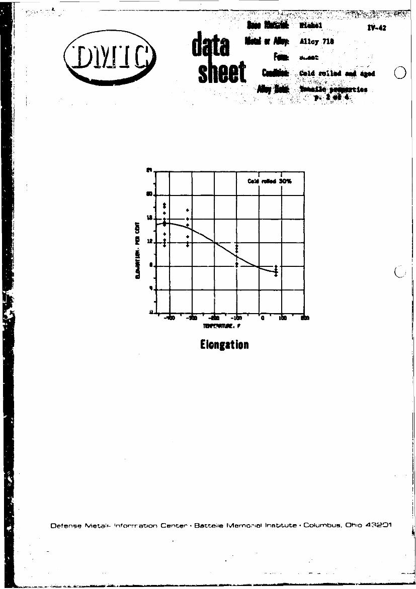
"'1-42
MW or Ahpy [email protected]" driil -'-.~ au " -,-
COW Cold r0e "84 -
Be
II
IF ami
Elongation
Oeferi•ie Met.•a'- rifo cyrat.son Cent.er-. Bet-ae Mlemo:-iol lrRtJi•ute - Columbus. Ohio 4,201

LOTI ftiIt4eITf~~~dI~UIfh £O011%$W-~w rSL 0011114l
"gist 61bNT IfSIl(LMto~~ .t .44r Ne l cc, C11 I.s$" ls 40PI CN
11117.0p. ofs. 4. -£086189MP~9 333 ac~6?. 6UM M31
L* allj F4. 21.0 oo46
late4. 1144.6 7.8 -. 2t e t t 6I 361. L3. . 47890 846 8.
186 341. 07. o6. PC sefs0 Se Oe I
CdSIC *.3i1936 3?.£ E IO )10% ' " 4.. 330-j 160.0 349. ISO?-.i L(SVPOt?
at~l~i j~ b~?.483 839.0 349.6 I,'.: L
VIELD S3AC TIWIL TI%(P0t FZ% 6A -106 816.4 P42.4 6.6 T
aIL PC (67 ?,!( LCS aa. 830.0 TS.9 *.
-43 0?3 ~ 91
711 0?1 114.0 69.0 1td" 14?.po ui~~ 'w(*?109
IGO1 110(467. 7fm1lLF (1.09 *.A.
LOT Novs( *413 20?.4 331.11 11.0 1-384 R74.3 P79.1 t.?7
SO.,Inga nWAn.. 060Et?19 ?S 231" 760. 1.4 1.m
ftwo 0.02 ft 10.3 PC STS(467W 680l PEN Its?F I00$ PSI C?6 %,! .0,A~~gq iCCC9111" k.x6( 0mq
-3o0 P6. 30.0 11.41
IO to 0 is T c0 .61P
Is ~ . I7067 eg"0tL pis6 of.6C018 j
hOP~~:1 0.8.4. P 1(6W.e uBO 3
-40 61.41W ~ 0.o 7. .~.~ t l4.# . PO64..3 4.
-18' ~ ~ ~ P ife.e 7 '.9 89. PCOP 94 - 61P '(6.. P6 94 79333.0 1,, . 33a.0 1.~ 3600 kay 30,94 11 00P3 Cfo (4
360. PS -.0 "6.0 v 864,9.1 .0 - $116ca . .C0 s 11413.0 849.4 1"1. 6 ..
.19 790 400 .
Dlef ense Metalts In( ormation Ce )ter. Battelle M ex~n Ir.¶.c'..) (oim hu. LO-ho c 4 3 201

7VW A
Inv ~~~i14
L~~ ~~it W*IA5 ,
Sr~~~~mr-TINK~~~ep 5)11 009TCSsw123/8 hr 13 /0b
V51LO SINNO" ?1455L8 CLOd It.I~ 201.ic th o
Pt. 0.38P PC OlmhIN6tW PC* $2p CIT I2 Co/d hft l "1'50" M/Ieh
P tool8 P$3 10#0801 I P SI MIT8 Z.v ht 132S mo v ht* +5310m b13.14 C01 relled M0. the* go
1A8.1. . 19. L 1325 F/8 hr* +5150 /0t
TI 10, 18.8 .8 .1250 Flo hr * 135 1050 cold felled 70%. the.W.
1210 P/8 hr +1150 F/10 hi
*la tetaroedato alwa priotr to asole
sat: 515??
Oefen.-se Metalnk Informaton Cente'r' - Batel~c Moro'-'al Institute .Co~lumbuJS. Ohic 4-9201

L ~ ____________
1~AAll 2dCSIO
'YEIT .TNORQ NSRS UR.ND NI.Ed~YNTNORD INV TRASSF,JA NED. IN
T E N .E CTO IT E S tNIT ARW100%1 w AR(wf w PAlrO R TA IN O T.. ARE W W 1 00 W I ONTEP ~ LO ##At 100 LOT PERK CET PI IIR E ETP A 10 PI PACN S 6IS PRc
SICS 20 . ISL .. .... UTR ...0.,. .Afl S . ... TESIE--- ----- RPTR600 4IY"0C9 C. NSR -20*0 IN5. -30(fsl NO.3 4 121.0Sn~ U-ag.i
is0 I0.$ RIM. -320 6.3 '129.0M#~ 26.0 1?1. 1303. 71 .) 149.2
00 20.1 170.1: 2*0.0I00 20.0 16 .1s7 .
bo 2.3@ 15001 11S4.LO E 7l000 2.3 640.0 34.0 cutm mme 51
1000 21.33 130.0 414.2000 .0 233.0 94.0 MOOCNEO TtNSILE Aldo RUPTURE DATAl00t 4. 120.0 233.6100o .010.t6. STRESS -Z E T4SILC---------UPTURE---1*000 1.010:0.0 3632.4 INTE NS I TY "toTC *EIN STES "A- RKD. IN
100 6090.0 903.1 TEMP. FACTOR STRENOTI AREA 1000 T10W AREA200 20.0 16.1. 1S0.0 2. f 10 0 1 P ERt CENT PSI HOURS PER CENT
loot 20.0 170.1 210.0 12.,000 200130.0 26. -423 . 2502000 20.0 210.0 73.0 -423 4.:3 2:19.01000 2005. 2610 -320 6.3 2234102000 20.060. 2?7. -320 a. 2.lOIS pq.0 70.0 433.4 7s, 6.33 19:.$
100 140 ,.0 1?7076 711 6.3 190..A2000 0.0130.0 7.
1000 20*.0 220. 9.2000 20.0 90.0 21.31 0 0 20 . 0 0 7 . A C C E S S I O N N A M ME R 6 1 1 7 7
2000. 1z"0 40.3 123.6 LOT 'AtqEN 61000 20I 31.0 2064.402200 213 70. 47? NO0TCHID TENSILE AND RUPTURE DATA2200 2.3 *. 9.I?2200 2.3 506336STRESS----TENSILE ---------------RUPTUft ---
SO .61.@ 7. INTENSITY NOTCHED EDO.-IN STR1ESS OUMA- eDc. INice$ I.: 4S.0 2511.0 TEMP. FACTOR STRENIw "CEA 2006 TIO% AREA2200 4.0 44.0 464.4 r A9 1000 PSI na CENT PSI HOURS PER CENT
:423 6.3 274.-423 6.3 240.
ACCEISSON NUPHEN1 61373 .320 4 214.0-320 . 229.0
LOT NLI*AEN 1 -100 6'.3 Z7l.1.100 , . 2...OTC-FO TENSILE AND inUTuT MAT& 7s 4.3 2:?7..
71"SL ?S .3 204.0
lSTENSITy NOTC..E at". IN STRESS 0*11.1 ago. INTP. A a PC T-34 0:90,:T4 a,"l 2000 lON AIIC6
to A 00PSI E CEN MSau" PoR cENT accM~IC. %u-*.e6EA 141
11:: N. I :: 1401:.6 LOT NOU-16E 4
is00 RN. 242.6 $6.6 16.3 NOTC-40 TENSILE 4"D "UTV"E DATA
22.. 20.6 36.0 *164. STOflS -- -TENSILE........iITO2206 20. 30.0 312 I.Ts.I, .uC-E RE.I TES 'O- R INi2t 20. 11.6 10 .I'll INT0*S NT RNT 40( -C0 a10 435f*L
2I6 26. 71.011III$ '40IM. S":2000 PS PR CIN PSI ."11%4 Pto MINT2*10 200 14.0. -43..3 4.
Z7oe 1. 10 21. -320 F.3 07.6
..5
16.1::
Defense Met;31q Infro;rnaitjon Cent~er, a~~2~ Merrmrial linýItA,t it-e . Co; -2fV~iu!.,. Ot) u 4320 1

4 L
2 ofCrISSION~ 04.0w -7Ccsotwoe"l
lo UVN 11WIa i
1.?N PILE.. ... US4 SII ---0? f9-StL --- ---- UTR
FOp.7CIOO S"1411 Anto 100 lea# ~ 1106Tt. POISl~~4T A( 10001 1t ANF 9 1000PI02 0 SfCENT PSI poom* OCR15 CEN F it 080 too OC* CEN PSI HOURS OC *twe
-'21 0.2 304.0 -422 0.2 I04.*.232 0.2 201.0 -120 0.2 Its.0
$-320 0.2 292.0 -109 0.2 264.0
-100 0.2 201.0
Is 0.3 22630
is 6. 246. A 114081.1 *8( 58171* 60 1 8
INTENS0ITY N5041(10 RED. In 1Sf ISS SUR. OLD. I*"OT-t KII % RPTR DTA1. FACTOR STA18(1?w AM& 00 1200 Ti REs.01C"(0IU 1141. a4 SU~S *0P K isti PSI Pea C~a? PSI oo1*1 P(s Cc"a
141(5(11, *O'C-10 ICES. J 10 5 04JOl*- "A 60. too .0113 0.2 "00.:?top. FACTOR S11141.. ARE Jo* 100 lIO AMA8 .380 0.2 no.
F 9 logo oil PIE CENT PSI Waves PER Cc"? I'S G 92.
-022 6.3 326.0-320 .,0.
ACCESSION %UV0K "5177 7.#.":ud IM0 fit bt. UwSaiLOTw0? l Ot. 1 4 IM1 bZi0 . I1t" Vie be
011(1 /9. b.0 . IMFleL
4OTC"ID 1(5111.9 A00 RUoPTURE 0AAIt41*r ddM "Gd
Defenae PSIa~ Iomtof* CENT PS 00rN PE Battee M1114,, wigtt~t I. C ub. 1116 43201e14C 4 " idre- 1,.4"

Vat1ime data for Allow )18 (cold rolled + ad) @boot at rosetemperature ad stress ratio AmC.33 (smomtchad". Rt 1)
CoaditLon: Solutioa treated at 1600 F. the* colo rolled15%. thea qaed at 1325 r/16 hr.
It Iduas: 0.063 tach
bf: 61"6
Seream •clea toOtst f• ailure
123.?• 126,00U131.5 "6.OOO194.2 )&.000153.3 $1.0001C. ! 157.000
274,000
) ,.7 12.00073.9 437.O0
$. am. Tepraturie
•. t 1.021.0c0
. _- ,,0.))
$" --SS U.IO. A *, . .11 t(b64tl~l I{-' ).

Bas Maeril xckal
it~ Alloy 7'18
F--S Seiee
Aihjflat& Cree an ru'pture
1101 160. IM .l64#0 1
eel 1 04.0 1404.8 .4444
444 11.0 244.0 044.4
0ot$ 216.0 ?$4.&a .9160444.
2.4 20.4 024* 0*.e
" "A 4. 40.* to ::,44 4 .44 ,... ?I4.#* to=)4 ,244 ).4 1411.44 *440 4 .
2444 lot. 1..4 .4431344110.4 .64* .. #
','I 244.4O 143 .4a 1 1 '.244 9064 44.18.4041404101
2 M. 13.4 12A.4 00t
1244 - 44.14 243.4 W444 IM1.b4M M
CR11-I14im 011,r 44Dlt11(41,(3

0o dAlloy 718 Z,4r
LI D 71~
Alloy 718 Bars, Forgings, and Billet
Annealed at 1750 F and Aged
Tensile Strength
See Page IV-58 for Heat Treatment Conditions
I)__ -- -

I'
0,t -e- -)c -Woo t
.2% Yleld Strengti.
See Page IV-58 for Heat Treatment Conditions
fler~c~N~.;lt In ¶f'~ C'r~.' frr~-.Ir. ~A~'l )~r fl ~ ý 7 ~2III I. nl r7 1

-V4-
rol
B - -
Elongation
0. - -.- - -
__ "_i_
0 I IReduction in Area
See Page JV-58 for Heat Treatment Conditions

.'A
~~ Alloy 718 Forgings Ae
Anele t 90 ndAe
M
4WIWNW
loc.
Tortv"W.~Tt F FOM
Elongat-------------------------
Sei ageIV-S fo Het Trstwt Coditcni
r-,F"tvr Bn- ije emor ; lr~ti'Uttl- Coumbuf5, hio 43 1 '

tiff eta Wvj
JAý
AC"SltOft 4~ A Steil AMMON wi-wim 61763
LOT WJ-OCP I LOT ML000 I
SOORT-YINE TfNIILF P*O>CPTICS S"OQT-TI0W TENSILE 04001011CS
v IELD ITOWQYM Uftl[L' CL P.A [Ito STREhereq 7F.SlI.t F.Lo" 0TEMP 0.0 PC S I fthet, POE" PC; TrIT '1.0 0.0; Vr I PC -S oth'al . Pt Tril
:Cý F logo I i:;o PSI loco pit CE MISr 1200 S 0 psi 1000 PSI Ctpmr Cf"T n1a
-423 241:'* 11 11:5 L0":0 L
1.11.4 a 0 Ro.m 11 .0 '... :.,. LISS.o ::Z3 Is? ?".0 31.0 " .0 L
10 ýr 166:5 1411:: 17:: 24:1 T24 :1, is I31 '1 - 2 1 1. S S S T.0 1*3.0 44 L .0 t".. 11.1
Sol.$ 14.0 3 -044b,# 20.0
24:1 14.0 ly.0 SArCeSS1000 huMCP 63741 .32 17
LOT " CA L
.31: 17:.o 11111 u 31 .0 11,10 L.0 .0 3..
M I 1 4 L
31.0 al.: L-Jto TO.$ rS.6 14'S.3
TCNSILI! 0*0010TICS -111,.210 1?7:23
VULD 21*11M4170f ft.* -320 M .1 '1TEVOILC CLO40 *;J.o 12.0 15.0 b
0.01 PC 0.1 ft 1votme's oto PIN Tes? :320 176.4 rIJ'o 11.0 21.4 s1000 051 lato Psi 3060 psi CtmT CfmT Me 77 1,11,
194 1 1::'" 0 L13:1 L aI :. , :*:01 134 1 74 L :310 L33:: L le.o 66.5 L
L '1:: 16:1 LL I"N
6A I:.. I"..
3:: L 03 112.p.01 1 1q. . *I, L loll:, 16.0 21 100 142.2 11:1 L :11.101 10S, 4 10.0 111'r.2 I I 1" 9 194 S 14.0 IT, S
1?4.4 N., :.41 LL :1111: IS? . a 144.0 21.0 IT.S
a 166. 11.6 L -110 194L '14, 1 ý " :'0' ":1
:01 4.0 S.0 1. :7 :;:,. 1. .1 o L24:7 ::.* 1 141.8 4.0
.:11 L
163.9 141.0 111.5 L
166:6. 1:3::64
CCIS1 10"',%'p" 'm 4316"Loy " I I so 16S.43 1171-1.
IgFIStLe P000torIcs ad 160.9 13.0 P7.0 S
19LO STREW" FIMIILF 1ELO46 X.A, :"0':'* .0 'S
ILOP 0,01 PC a I PC I Tog"ev . Ft* p" Te0 Ito# psi 1#;9 Psi loco "I cc ,, CtFol 0 1:1
01 1-0:71 ACC0.51104 %~ A 4?546
1. L LOT mpossm 13
OS.0 14.0 16's124-10 171.1 16.S rl.9 IMO*T-TINE TOOM pow07111143 4 `:" o "
IFIELD YlPf"I"'4' ::. L 11431LE CLOftd a.&.
lok]:f ".twm "E. ,I. ....
1!62.4 171 0 LL I .:;I*, 0"C' '000 psi CfftT Cc%, n1a132.6 it L33:* ,4:"b L 74 160.0 roz.0 10.0 &*A
"1 3 .4 612 3. 0 's L 160.0 10.4 86.0 &r.0136 3.S L
3.0 L174.6 14.0 101.1 L 1 41"
106.2 24.0 28.7 L 1!40 18S.049 139.3 170A Is.$ P3.9 L00 141.2 102.1 89.0
[Dr!fnr-vno-- Mt!t-.6c; lriformnur)n Cruntjý!r' , Battehs'l Memr)rio! 1n!-.trtut;#! 4,-J;?-Ol

-4
~IIIM~V V
ACCESSION .u-6104 4009 A CCE31bOOE Pkuo'0 47-194
LOT Ps4(0 I? LOT NumaM0 5
TILLD STI(4OTM TOW5LE tL4 *.A. YIELD0 STRENGTH IFSILC ELO"4 P.A.
TE.. 0.0 sew. C r2*. Pf6 P00 TEST ?wp 0.02 PC 6.2 PC rrTc.,4?H Pn P"r VV1
S 100 10 10 PS0 Or00 PO Mfg" C. lose ps J00ose00 PSI '640 PSI CE%? CENT? nip
1*0 133.6 360.6 To IT!.) 1:'1:4 120 3.
3400 02.0 605.6
ACCC0IIOOO 00J04006 4159
LO k"1 MPCS(I. Ipr T9 LOT MNw.006 A
SMOOT-TintC T(4I!L( "Offoy6?3(YIELD $0 NO Pf1 ?('SIL tLOPOG P.A.
TEO&' 0.020 6.2 PC ?3(~i POP PO 1(0 P 0 PST 10 0 60PI C'? C,? fi
S67 1,: 16 1: 7 T: it93 is.2 1.$ 26.2
3200132.3 16. 20 3. 637. 6. 30 2.10 170.15 391.0 It.@ 30.4 1
4ccý-S0Io' W-Jef* 0-196~ ACCUSIIom 644140( 41094LOT? 140psP(6 P LOT? WsJ"CM0
S.OW?.1"I0 ?04.OTLc P*00aT6I( S..00?-?lMC T1'sSuLP P6OP1UOTIF1
Y1(10 SIPCW94? ?0.IL LO". 0.40.L 1040 ESLE f~3 PA
t" 0.0PK 0.2 PC IT "$014 P(1 Cfi S~tmy PER1 OCR601 ?f.SLZ (2 T
P'r t;:% 100 'I 3000 11 3000 pit CENTC CET's
10 1114.1, 100.6 10 24.4 Ti 114.1, 212.1 19.) 32.2
70 14. 20n. 124 oo ~ 73.t 161.4 11.0 14.9
1*0133.1 100.3 it. 0 1.54
ties I0."9' 1"".! 10.01 3.1006 14S.? 1712.1 1.. Is.3Acslf 00 1 70
LOT 14Um6(I a
S..O?.?1C vChsIlLf PVOPCRTI(14ccOillom wjA(0 fP10N.ALOT M6,60 0e I12. tLO 9OCIUPO TENSILE (106.4 30
00.?12 (SIVPO.000:~PIS3, P1111 10e0 PSI1 :1~l Ct~of l? It 1
YIELD0 01714tw4 Tt:.iILC EL044 .~ TO 147.3 112.3 14.0 16.1s 1
It". 0.0a PC 0.0 PC 74(01 (P 03 10 !!0,: 3179.4 it. 2it I
F ties psi 1000 psi 6000 pi Cý.0 CENT FIT T0 IS*.* 160.4 30.0 20.2 T
10131 272 10.4 640. 0. 1. 0 3.1 1;
TO324 20. 50 4134 131.3 144.3 ;33.0 23.3 T'11. 124.2 206.0
to* 11.295
36 4. 100.1 16.2.* 1-~o1260 320.7 340.6 12.0 24.4 1
100366 1421.0 is.? P6aIle 100127.3 143.9 13.4) 23.1 1'
I'ci00lo.0j""0 C041-Ibcf%31 fl4469(611,94
LOT .'sJ-46 a L0? 690.64 9
,;(tu S1.V'.'01 7f. ILE 1LO60 '.J ELL' 676(61164 TENSILE0 (140 P.A.
I(. 4.02 Or 0.. PC 513iN.9T" P1C1 P29 It2 ,C.0 0.62j PCJ 6.2 C 47(6 PC0 PER 1001'7 1006 041 1^60 PSI to,# psi Ef. My.. m0 1CP6 100 PSI 160 psi CEO? COO.? ni
10176.1 344.6 14.0 2S.3 70 140.? 364.4 32.0 .21 4 T
0 1.3 120:10 293 7: TO 4!. 100.2 13.0 1'..' 117I:1,.',6. 33.1 70 149. 3106.4 3 3. 244 A
7: 9.0 3. 13.4 2315010 3~113 13492, 3, 2.
lye37.? 160.0 11.0 M0.
16~~~ 364.4 3,0 3.
To 349.3 08. 6 06. #
*v, ,' f 1n f r) r otn I ~ ~ r n Ilt~? Mro'mnrid Iituto.C;:tu~rnbuc, Ohici 413201

VJAA
ACCESSION 4~~01E 06002 Eli *SSI3E KJONUIN 07014LOT NURSER to LOT NUMIVR dl
09TT2M111 TENSILE 04P*WmT1E 10007-TIME TENSTILF PROICRTIES
TicLa STRENGTH TF."IIL.1 ELONS N.A. YIEL0 STRENGTH6 T~ONSLF. CLOoG N.A.F i000 PSI 1900 PSI 1000 PSI CENT CENT nto P 1000 Plot 1000 PSI 10100 PSI CEN " CENT MI1R
To 1011.0 IN.*1 let's 23.0 36.0 TON? 1190 568 91. T.IES1W.0 a0, 133.5 11)0.0 23.0 4?. 0120 196 1 . v 0 2.7 6. L
tos 144.0 163.0 199.0 23.0 330 20 10. 1. TE1SIL1 1LO.I ;1.0. t220 212.0 130.5 I 230o 0. C TEN,. PE ES T1To 190.1 120.3 t2.1- U5.0 36.0P 200SI 00PI 200PI CN CET 10t30 101.3 142.6 2943.0 21.0 36.0 11. 0. 2.0 1.0 4.
1100 132.0 136..1 JIM. 21.0 469 LM O im 71
SLI 10. P76 41.2 1. 3.0 LOT NUMBERt a?
lateD SYRCO. T 133.0L CLO~e 101 4.0.lteM 01.02 Pp a. 0S4 26.0 ICWOROI PU PE ET 00-TIME TENSILP PUO#RZESIn o06PSI 116.00 losez 23.0 CEN C.T YIELD STRENGTH TENSILE ELON4 N.A.
i0n30 20. 00 4. TEMP 0.02 PC 0.2 PC 5T7!4946. PER PEN TESTr30: 1 . 131.2 113.0 1 0.. 312 7 4 . 710005 20? 3 .
1 "9 193 ~l0 I.0 M. F 300.PI9 e S 145.0 PS2 CNT CET1200 O? 122.2 703.1 21.5 42.0TO 17 9.260 180 0s L
lade 132.0 14A.? 172.0 IS..&5
11001330 20.0 0.0 1.5ACCESSIOA MU0JOSI 07041SHOITs,~ 1E3.1V 203.9 2.0 2. LOT NUMOER 01
YEW 001 o 0.1PC SRENGH PE PER TFTSNOPT-TIME TENS3ILF PROPEQTIESr og 91 ltsPTgg1Oo PSIOE CEN7 CNT il YIELD STRENGTH TFNSILE ELONA N.0.ToO 1 WO. R 760. Z 423 TEMP 0*.O :I 0;,~2 PC' S TREWNO PER PEE ,TES
F 20 0 PS OOS 1000 PSI CENT CENT ?'10
70" 134.0 174.s 207.0 6S. 032lees. 13290 07W T 6SIL 21.0 "0.0.1200 40.Q.3 211. 207.0 20.1 35.0t L
Pif 20609 011. 13,41 44.5 22000 PSI. 14EN? 1EN 1 2.23
1.0 210 103.5 262.0 01.0 37.0 A CCESSIONS WfoMEI 0)214Tied 10. 123.11 104.19 . 22.4 4. LO
T NUMICI so
SW000-TIMk TEMSIV. 4ýAP00.0111ACCESIZON 'WE'ft 061o4 YIEL0 STOLNOTM TENSILIE "L~046 D.A.L. 4osa 7 TEMP 0.00 PC 0.2 PC S TxcNGTH PER PER TEST
9r-iR 1gzt 060 PSI i000 PSI 1000 031 CENT CENT Ito70OTTM 1 SIE10 RIST 166.8 701902. 20 .70 70 .0 L.
,SILO STIr N TESILE CLOWG N.. lif0 1120.0 20..0 167.0 25.7 P3.0 Llaw 0.ofl PC 6.1 6z S78(090w of* PER roStP loot Dot Peel k~l 1000 911I CENT CErNT film
To 240.0 270.0 294.4 210.. 34.0 CESO "o a 641Is$# 116.% S231.0 14.9 :1.4 1`6.7 L. LOT NSSI4s 4, 071
61416 ~ ~ IitoS RENT TE NSILE '0 4
PC6
N.A.
LO 4001011 To EN 0.02 PC 0.1 PC STREWNT. wto oER VEIT
IPM111 F 00 lo s I ps 2000ps lc PSI 2~ 1 CENT CENT Mtn
V.1. Su VftSL (Ll *.4. 1: 274*:0 :0,: LSave 0.41 or0 45.5 2. 20014.0 P.s of*.1qtie o0 I 200 "SI 2040 011 '11% CENT MIS 0 1,. 2.) 25 1.0 2.
'od 118.4 21340 1%4.0 09.' If. 1. ACESO O N 0 1
0v0 1)0.0 NO2. 011.0 12).t70 Irv t 11014 NA'a. 2'.4* 04. 0.0. PC. ST O"" t K VI
~fen Metls rfornat20n 1cte 160 PSIe Me ora "I ,totut oil C ENTbs OhoT 4320to -.-. 0-17-.1 1..--1 11.6 0.) -
N.4

-r
P. 8 of 10
ACC[SIN¢ WMNuol 6761|4 ACCESISON NUMER 67614L.OT NUMBERA 9 Lot NUMBER loo
SNToTIME TENSILE PROPERTIF.3 SNORT-TIME TENSIL. PROPERTIESYIELD STYN06TM TE4SILE CLONS 0.. YIELD STRENGTN TENSILE ELONS M.A.
Ito .02 PC 0.2 PC STRENGTH pro PER TEST TEMP 0.02 PC 0.2 PC STRENGTH PER PER TESTF 1000 PSI 1000 PSI 1000 PSI CENT CENT min F 1000 PSI 1000 PSI 1000 PSI CENT CENT MIR70 'I4.Y 1T7.0 149.0 20.1 32.0 L 70 139.5 169.S 190.0 25.6 23.9 L
70 145.0 172.0 197.? 25. 23.0 L70 140.0 1',U. 194.0 26.6 26.1 L
"ACCESSION NU•BER 6761.LOT o•'UMBER ore
ACCESSION NUMBER 06716
$%OIT-TIME TENSILT PROPERTIES LOY NUMBER 101YIELD STRENGTH TENSILE[ ELONG P.A.
TEMo 0.02 PC 0.2 PC ST EN.OTY PER PER TEST SMOOT-TIME TENSILE PROPERTIESS11000 1000 PSI 101 PSI CENT CENT nIY SYIELD STE H TENSILE ELONE .A
70 14?.S IB30S 22•.0 16.1 3A.7 TELP 0.02 PC 0.2 PC STRENGmTN PER PER TEST1240 125.0 145.0 179.0 21.4 360. L 1000 PAN 1000 PSI 1000 PSI CENT CENT nIp
70 136.5 163.5 1418 7. 9.3 T
ACCESSION NUMBER 67614LOT %'*AA 09 ACCESSION NUMBER $781ALOT NUMBER lo2
SORT-ME SOTTI TENSILE PROP.RTIES
YIELD STReN0TY4 TENSILE ELOneY P.A.SHR-IETNLEPORISTEWO 0.02 P. 0.2 PC SYPEr.0Tv, PER PER TEST YIELD STRENGTH TEOSILE ELONO R.A.F 1000 P.1 1000 PSI 1000 PSI CENT CENT niR TEMP 0.02 PC 0.2 PC STRENGTH PER PER TEST
;F 1000 PSI 1000 PSI 1010 PSI CENT CENT fIR7T0 ;'48.. 174,0 To2,5 10.1 38,11200 131.9 149.S 174.5 R0.5 32.9 L 7T 129.5 1600. 194.0 27.8 30.0 L
70 129.3 103.0 201.0 2.4 20.0 LTo 137.S 16S.S 196.0 16.9 23.2 T70 13S.S 161'. 195.S 16.0 24.0 T
ACCESSION NUMBER 67614
LOT mum"ER g0
ACCESSION NUMBER (1764S14ORT-TIME TENSIL' PROPRERTIES LOT NUMBER 123
MIELD STRNOTH TENS•-lE ELOIJO 0.A.Taw 0.02 PC 0.2 PC STRENoTm PER PtR TeST SNORT-TtME TENSILF PROPERTIES
P 1000 P.• 1udo PSI 1400 PSI CENT CENT mil YIELD ZTRINBTM TENSYLE ELONS R.A.c T 19.4 TEMP 0M02 P. L.0 PC STREN0TH PEn PER TFST
|4006 1F0.9 715.0 A).? 20.4 L 1000 PSI 0000 P No 1000 PSI CENT CENT nIp!06.9 126.1 1%9.0 19.7 23.5 L
TO 123.2 149.S 101. 9.8 9.5 Te0 118.S 149., 1s7.0 8.2 11.0'0 j.3S. 100.0 145.0 27.' 32.? 1
ACCESS10t: NUkPKE 07614LOT NUMBER 91
S$R-l*4 ESILI POOPEIPTIES JCCESSION NUMBER 07610YIELO STRINGYT TENSIkE ELO" N.A. LOT Nu.MBCR 104
TEMP 0.02 PC 0.1 PC STREN44T PER PER 7E1?P 1000 PS1 Ss00 PSI 1000 PSI CE,47 CIMT f:0 SNORT-TIME TENSILr PROPERTIESis 157.% 19..0 200.S 2.9 32.80 L YIELD STRENOT0 TENI11 11LON6 C.A.
I TlIe 144 S8.• :.•|.0 22.4 30.1 L TEMP 0..2 PC 0.1 PC STRENGTH PER OCR YEqTF 1000 *Sl 1000 PSI 1000 PSI CENT CENT MIN
To 149.0 ITS. 1078 12,7 4.9 L7% 149.4 174.I 11.•5 80. 11.6 LACCESSIO 1 M•UNBER 0041'
LOT NUMBER
S..O*T-Tit TENSILE TIE ACCSION NUMBER 67604
TI1LO Sit RNOT" TENSILE ELONR N.A. LOT NUMBER 10%T[MP .02 PC 0.W PC STRY.k,4 ONR at* TrETI
P WS PSI 1400 Pit logo Pit CENT CINT 'VIsSotW1 TMI POE IST7 1113.0 17.5 167.28 11.- ISS 7 vio STRNT[Tn TENSILE CLONG N.A.14 I0.5 1•0.E 198,1 10,0 10.4 t T5MP 0..1 PC 0.2 PC TY M PEr o (R TESTY, 144.4 00.0 104.5 IS. T 16,1 T F 10P0 PSI l0a0 PSI 1000 Pol CENT CINT nIR
M1@0 143.% l6(, 112.S 10.4 IV. 'Ill% 126. 13,1. 121.% I&.8 IS.3 T $4, P 199.* 14.3 I3.9 T10 24*.S 0 111.2 l%.% 20.1 04.4 T 0o 1|4,0 • I94.s 16. 22.6 I
7o 1Ma.0 16, 0 194.0 1RA4 6.0 L
is 14.,8 173.0 194.2 0 42.2
Oefense Metals information Center. Battelle Mcmorial Institute . Coiumbus. Ohio 43201

ACCESSION NUMBER 67614 ACCESSION MNUMER 67614
LOT MNUGER 106 LOT NUNRIR 113
SHOOT-TIME TENSILE PROPERTIES $NOT.TIME TENST..A PROPERTIES
O.YIELD STPENVTHMP TENILE [LONG .. YIELO STRENGTH TENSILE. PLaS ';,A.
TEMP 0.2P 2 CP STREGT PEME TEST TEMP 0.2 or 02P SiNY PER PR TS
F 1000 PSI Inai PSI 11000"PISI CIENT CENT MID F 1000 PSI 1000 PSI lon0 PSI CE:PT CENT MIR
ACCESSION SU4,EN 6749!!
ACCESSION NUMBER 67614 SNORT-TIN4E TENSILF WPOPYRVICS
YIELD STRENGTH TENSILE ELOWG P.A.
SHORT-TINE TENSILP! PROPERTIES TEMP 0.02 PC 02 PC STRENGTH PER PIER E
YIELD STRENGTH TENSILE ELONA 0.4. 100PI 00PS 100 SI CN CET '6
TEMP 0.02 r!: 0.2 PC STRENGTH Pelt PER TEST I7 111.0 173.0 2016.0 20.% '2.0 L
P 1000 psi 1000 PSI 1000 PSI CENT CENT MIR 1200 134.0 152.0 1,0.0 14..4 32.3 L
TO 141.9 174.5 190.0 12.9 10.9TO0 141.5 174.1 19R.0 12.9 13.2 TTO 1 19.0 171.5 190.0 19.1 16.6 TTo 131.1 171.0 196.0 1'.2 10.5 770 130.0 169.1 200.5 16. 23.4 7 ACCESSION NUMBER 4765?
TO 141.9 177.0 200.0 7.9 10.1 1 LOT NUMRER 1nt0 137.0 160.0 19741 4.1 6.? T
SHORT-TINE TENSILF P*OPFRTIES
YIELD STRENGTH TFNSILE ELONO P.A.
ACCESSION NUMBER 67614 TEMP 0.02 PC 0 .? PC STRE*,4TH PER PER TESTLOT NUMRPE lop P 1000 PSI 1000 PSI Ion0 PSI CENT CENT MIRE
SHORT-TIME TENSILP PROPERTIES 7? 111.0 179.0 P12.0 21.9 40.0 L1200 135.0 193.0 174.0 17.S 39.6 L
YIELD STREW4TH TENSILE ELONG R.A.
TEMP 0.02 PC 0.2 PC STRENGTH PER PER TESTF 1000 PSI 1000 PSI Joao PSI CENT CENT MIR
T0 130.1 163.1 161.5 23.4 32.S T ACCESSION MNUMER 67607
T0 134.1 140.1 163.1 10.4 33.9 T LOT NUMBER 11
70 131.1 161.0 104.0 14.6 201.0 TTo 136.5 163.S 194.0 11.0 24.470 143.0 174.0 192.4 7.0 13.0 T SA.OPT-TINE TFNSILE PROPERTIES
70 144.0 17S.5 197.0 12.2 11.1 lt STEGHENIE LO PA
T0 144.1 177.5 197.4 13.7 16.1 7IL TEGHTNIE (OG 04
T0 135.1 I71.1 195.0 14.6 16.4 TEMP 0.02 PC 0.2 PC STRENGTH O'ER OER TESTF 100 PSI 1000 PSI 1000 PSI CENT CENT MIRO
77 21.0 177.0 209.0 10.7 33.3 L
ACCESSION NUMBER 67614 20 3. S. 7. 0? 3.
LOT NURSER 109
TSNOUT-TIME TENSILE PROPERTIES
YILD STRENGTH TENSILE ELONG R.A.TEMP 0.02 PC 0.2 PC STRENGTH PER PCE TEST
F 1000 PSI 1000 PSI 2000 PSI CENT CENT MIRI
70 14.9.S 169.1 109.1 13.0 13.0 T
ACCESSION NUMaER 6471'0.T NUMBER 110
SNORT-?TINE TENSILE PROPERTICS
YIELD STRENGTH TWNILE CLO0.6 6.A.
TCMP 0.02 PC 4.2 PC STRPIMITM PER PE* TESTP 1000 PSI 1000 PSI 2001, psi CENT CENT MIR
70 146.5 T17.6 149.% 16.6 P2.070 147.0 174.0 297.3 126.5 22.370 244.s IT0.$ 103.5 21.p1 4.4
IT, I4T: 172.1'1 ,:, I'.' 6 27
70 14a 7. 0. 42 1.
Defense Metals Information Center.- Battelle Memorial ln!7vitulte - Coltimbus Chirn 43201
4

4JrwTensile properties at cryogenic, room, and elevated temperatures
for Alloy 718 bars, forgings, and billets.
LotReference NO. Heat Treatment
50031 1 "Aged"63742 1 8 hr/1325 F, 8 hr/1l5O F63743 1 45 min/1950 F, 10 hr/1400 7, 10 hr/12OO F67595 11 1 hr/1750 F, 8 hr/1325 F, 10 hr/1150 F67595 12 1 hr/1750 F, 8 hr/1325 F, 10 hr/1150 F67596 1 1 hr11750 F, 8 hr11325 F, 10 hr/1150 F67596 2 1 hr/1750 F, 8 hr/1325 F, 10 hr/1150 F67596 3 1 hr/1800 F, 8 hi-/1325 F, 8 hr/1150 F
167596 4 1 hr/1950 F. 10 h,-/1400 F, 10 hr/1200 F67596 5 1 hr/1950 F, 10 hr;1400 F, 10 hr/1200 F67596 6 1 hr/1950 F, 10 hr/1400 F, 10 hr/1200 F67596 7 1 hr/1950 F, 10 hr/1400 F, 10 hr/1200 F67596 8 1 hr/1750 F, 8 hr/1325 F, 10 hr/1150 F67596 9 1 hr/1950 F, 10 hr/1400 F, 10 hr/1200 F67602 20 1 hr/1750 F, 8 hr/1325 F, 8 hr/1150 F67602 21 1 hr/1750 F, 8 hr/1325 F67614 78 1 hr/1700 F, 8 hr/1325 F, 18 hr/1150 F67614 79 1 hr/1700 F, 8 hr11325 F, 18 hr/115O F67614 so 1 hr/1700 F, 8 hr/1325 F, 18 hr/1150 F 067614 81 1 hr/1700 F, 8 hr/1325 F, 18 hr/1150 F67614 82 1 hr/1700 F, 8 br/1325 F, 18 hr/11S0 F67614 83 1 hr/1700 F, 8 hr/1325 F. 18 hr/1150 F67614 84 1 hr/1750 F, 8 hr/1325 F. 18 hr/1150 F67614 85 1 hr/1750 F, 8 hr/1325 F, 18 hr/1150 F67614 86 1 hr/1750 F, 8 hr/1325 F, 18 hr/1150 F67614 87 1 hr/1750 F, 8 hr/1325 F, 18 hr/1150 F67614 88 1 hr.'1750 F, 8 hr/1325 F, 18 hr/1l50 F67614 89 1 hr/1750 F, 8 hr/1325 F, 18 hr/1150 F67614 90 1 hr/1750 F, 8 hr/1325 F, 18 hr/1150 F67614 91 1 hr/1750 F, 8 hr/1325 F, 18 hr/1150 IF67614 99 1 hr/1750 F, 8 hr/1325 F, 10 hr/11S0 F67614 100 2 hr/1750 F, 8 hr/1325 F, 10 hr/1150 F67614 101 2 hr/1750 F, 8 hr/1325 F, 10 hr/115O F67614 102 ' hr/1750 F, 8 hr/1325 F, 10 hr/110 IF67614 103 2 hr/1750 F, 8 hr/1325 F, 10 hr/115O F67614 104 2 hr/1750 F, a hr/1325 F, 10 hr/1150 F6761'. 105 2 hr/1750 F. 8 hr/1325 F. 10 hr/1lS0 F67614 106 2 hr/1950 F, 10 hr/1400 F, 10 hr/1200 F67614 107 2 hr/19S0 F, 10 hr/1400 F, 10 hr/1200 F67614 108 2 hr/1950 F, 10 hr/1400 F, 10 hr/1200 F67614 109 2 hr/1950 1F, 10 hr/1400 F, 10 hr/1200 P'67614 110 2 hr/1950 F, 10 hr/14C'0 F. 1.0 hr/1ZOO F67614 Ill 2 hr/1950 F, 10 hr/1400 F, 10 hr/1100 IF67614 112 2 hr/195O F, 10 hr/14O0 F, 10 hrIIOC, F67614 113 1 hr/l800 F, 8 hr/1325 F, 1S hr/110 IF67657 9 1 hr/1750 F, S hr/1325 F, 8 hr/110 IF67657 10 1 hr/1750 F, S hr/1325 F. S br/1150 F67657 11 1 hr/1750 11, S hr/1325 F, S hr/11SC F
Defense Metals Information Center - Battelle Memorial Institute - Columbus. Ohio 43201 i

01
impact properties of Alloy 713 It craotauIC tmpesaures. Itbh 41l1annealed and be•t treactJ speciawas wre tested. Specime. were mecMh-..d tothe dLneaitocs shoms In figures iroa standtd Mo. S taper pies. IUe *ubstsadardsize was mecessary des to the 30 It-lb capacity of the testis& machias.
leat treet ,t utilixod vas: aiW at 1325 F for 7 beors. farasc,cooled at 20 V per hour to 1150 I. sad sit cool-ed out at furnace.
Impact Isargy to ft-lbh.Test Temperature Allay 718 Allay 718
K eAse led most Treated
300 8.3 1.0300 8.1 1.0
300 7.6 1.0300 8.4 L-1300 70l
aon. 7.9 avn. 1.0
194 3.1 1.0194 8.3 1.2194 7.4 1.0194 7.0 0.9
avn. 8.0 avn. 1.0
) ; 8.2 0.14
77 ?.3 0.877 '.0 0.777 7.$ 0.7
avg. 7.4 avg. 0.78
20 7.9 0.720 7.6 0.?: 7.6 0.8
•o7.3 9,11
- .6 ;.0.1;
set: KI2C 62M*
0 0
*OT¢C OmIN$ O.O" 0
D~ef en. MetasI mt ~rMetao-)n C41ter - B tt4e,; ywrxr ke - Cok ~ . O1't o 4320

Ab L0 Punmoched (Kt 1.0) reoc~att bendin fatl~as data at rom •peract, (ew OOh*LeCreated sad aged Allay ?tS bar, a -01 (A -o) bease treated as felleme:
Selatim created 1750 F(1 br.) A.C.Med1325 IP($ br.) F.C.
fted 1150 11(0 hr.) A.C.relo: A
law ¢Clycoat, Kis ¢yclog"Stress Stressl
j# gne -Lk-i Cycles IMMI1STO
100.0 121.000 Failed94,.0 2"3,000 Fa8i1ed85.0 10.163.000 tam outW0. 1.193.000 Faled
87.5 2.80".000 faleadW6. 10.023,000 Failed
87.0 11,071,000 am set105.0 09,000 Failed
100.0 12,000 85.0 3,320,000 faled100.0 6,000 $5.0 930,00 Failed90. 45,000 85.0 1 .•6I000 ref1ed /90.0 11,250 83.0 10,0A4,000 am esa90.0 25.174 85.0 3.354.000 Faled
1i00.0 1,300 81.0 4,6",00 y"fled100.0 1.300 85.0 940000 ftied100.0 730 82.0 10,027.000 am out110.0 286 82.0 2,978.000 Fatled
S103.0 437 U2.0 11,071.00 am setS110.0 1" 82.0 27.081.000 tam outS10S.0 Ms5 82.0 24. SmA,= am oat•9S.0 3.250 82.0 10,022,000 am set
95.0 65,000 82.0 3.963,0m Failed105.0 Us5 82.0 1.274.000 VaiLed88.0 50,000 82.0 936.000 Failed
*Tooted at too CPO at SAICated stress revel to uiedtced SM&W ofCe te$•Wolevied by comeatematl bIg~b C•lee teetiag to 107 Cycles or fallen.
we T~ested at 10.000 CPO. wte. o.
L -
Failed

~wuww
120 1 jAlloy 71. Saw
r2 Rom tiseraturrg
it - -1
0,0
70
Cycles to failure
Duaeccbd -.0) MstiMS beading fatigue beabvior (S-M) of solatiom treated saddoale Owd Alley 71S bar azrt i "Atuft. 3.I (A -t )
Ref: A
0 e "vm," .Ii

.smsabie (we* 1.0) Po11-W.1 tolet.a do" n tn m 1000 V gm4063 Wd Alley 718 ovlipw" lastqa* It 0 (A *1)he fae
I'09 - 116Fl hr.) b.C.
NMI* lepla to
IT ~~170.00.218.0 4.132
211.5 1.906
19n.0 AU
180.0 VA
130.0 226136.0 2.%l0
190. 22.179126.0 11."2120.0 11.9w2126. 2.1"0
T.. OVA"* aS Q-~~~~* wod ISO"p- *P-
I (A
us'~T
C"I t Us. $a
ftob tB4 - V.S) rull-"As two f"So Imaw" uwwI. ($-on 4 Am&,* ft"O'.,l 1 t" q~ It OWS - toreow' e soi lo I a * 0 (a - 8)
Ee.W@~%S M~et&%* b 009vet~ Crnr-w - EBoteft %AmortW b-mt~bte .Ccviunlx C~o 43201

avbatji tmsatad sad da~1 fi MIST 718 @ftg1W, It - (A *1) WKa tW~fted
ftlatiM tzestd 1736 F (1- sr.)C.so 1325 (f heA b Pý.C.
Wtd IllsFr (is hr.) b.C.
Mae: A
low ~Sr crews to
170...4*
4 ~190.0 3
lowI.O0 2003
130.0 1. '120.9 0.01w
144.0 6.699
*ft11.d WA. *fbat*ft. 36-1%-L99bToo see": ýs tý
- ta? an tw, f
-~w spa"__ -- o %to
* 100
rioted SC M U 4" A1-- a fe Sat0 #am of ....- - t -ssa
C41fenso- ma.aa*a bvcq Baatf Pw1rx-o Cokan1
r C-a-- 4-4,p

amE MUeiUI Nickel
a~ UudAku Alloy7 18i
DI fFea 21arse £org" tu billets }
p. lof 5
SM ~ ~~ ~~ OIL WW If tENTM
STn.. ,T~m (~gr.L•
'I-
Strsss-Rhptur Tius
See Heat Treatment Conditions on Page TV-68
0
c-fc'ns3 motoin Information Ce,,•er. Battelle Memoriol Inntituto- ColumbuB, Ohio 43201

46
p, 2 of
Alloy 718 Bars, Forgings, and Billet
Annealed at 1750 F and Aged
1W - -~lw.- m
Ma f
Rapture StrengthSee Heat Treatment Cond&.tioits an Page IV-68

F 'F
mwI~~~~7 .t. .ecs* .u l ...
Temp. to, Itic Pool egat CSEp 916 A& a~t fl ftwo too: ?V1S 90 "a Cc" C1119 V. AS 5,79p" P" 18M9 P9 se990 WITa tag Comt 1I,, 0 psi ~0u9 Poo"l WOQ 3 Cape? 9120 UNIT tUST
1)4" life0.9 .9 al w INIS .3 .10IM0 7?*0 f96.30 6".sqleu ao * .900
lit$4 131.0 3M4.601106T@ 4i~o #so l I113 0.0 .0. 116
LOT W9* a ~l Oat list 1189 179.40 1.11
its: I$:: 394.30 so. l
1)10~ ~~~ 1101~ . 1
LOT "own ?a
LOT wijsts 20 00:604.t W3to a"s m~uln DATAlTIMIb Cuss- let" a~t! STML WDM mw5
Itom. 1000 Tian P9s Cc%? ,:::. If, *a Arras
?fm t I NDi 1CAvgO. 1)9, '1 ~ 'It *9 s ' 1,:. 110.01 70Jo.6 ""o P" , '' 43)to~o luov I :xf A.=oe 1.0 .4 "1*#
WOURIS -a "ues sCiUAvA o/A c /"~
Ift 'I 19 1) Let .si01f ?s13441 se 10410 Si.
twa o e ti. IW Ti weIS CvtN ewE, IL. a. WtrE"f 11! va* WI "s~a we raf ctt ConPE Clot MT?
LOT %V-.01 Itt56.9t.
~l~~. ~t &£.O Wm-Ttul 0*1TS
STOP14 &.1 11ttiL m.6J935 V"0~cu. Ito 1*1- or FC%% CV.3 .gu go "'to LO wuo f
v~ wit* C5.-Im 0.5 *41A 0999 C2,4 itsi eats
lk9#t.: "a, rt" fW.l -10 "Qa "ma01,aTS
Is S 164
lfS isr ft~3F In.*nUr er, etI ~r1r~.Ir.~t~~ nta~.O~ ~2
U* Los, . *

ST~CCESIO ftN*K 6~~07616 '~ ACCE~iON NUPIER 67614RPTE
Lof WMIRE or LOT NUMBER In
0113 -0460 C V490 VAN RUPT 1.E DATA O RI GINAL CREEP AN D RUPTURE DATASTTIi PAT--N oe TOTAL ARRT01NE "AID STRESS DN- MNRT OA UTR At
TEsp. lost Tien IWO CENT CREEP 91. NA AfeTe Temp. l000 TInN Pro CENT CREEP V. 4A Aricav P11 NOURS Pro MOOD- PEN CENT PEN CENT TEST IF PSI 04OUNS PUN "DUN PER CENT Pan CENT TEST
life 75.4 %4.IN1.3 . 4 1.340 TS.O 41.44 11.31 23.3 44
ACCESS ION Rdu"P 07414
ACCESSION WNUMBR 41043LT4U-em aLOT W NK LO NMER 9
ORIGINAL CREEP ANO RUPTURE DATAORIGIAL Cct ND UPTURE DATA
DRRIA RE$A? TOwls DURA- MtN WAe TOTAL NURTUNE "AND
stptss OURA- "ToN mATe TOTAL RUPTUE "W TE-N. 1000 TION PER CENT CREEP EL. *A AFTEN"Zoo. 1000 TION1 Pro CENT CREEP EL fA AFTER or PSI -OURS prN "OUN ME CENT Pan C11NT TEST
if psi MNO.jI PUN NOUN of* CENAT PCN CENT TEST 1300 7S.0 47.2n 19.5 23.7 43
life 75.0 114.110 R.0 10.5 44
ACCtNsION NussER 67141LOT NU-1BER 94
ACCESSION NURSER 47b14
LOT j0Kn 84,ORIGINAL CREEP AND RUPTURE DATA
ORISINAW. CRlecP AND M.JPUR DATA 510410 DUNA- NIN RATE TOTAL RUPTURE HNDNTNo..P 1000 T1ON PAN CENT CREEP EL NA APT..N
oYREss OURA.. RIMar NT 'OrAL RUPTURE "A"O P pit POUNS Pro NOUN PER CENT PER CENT TESTTEmp. lots ?lIoNo Pwe CENT CREEP EL Na& &fTeR
,,: a t : NO U NS Pe e NOU N NE.? CEN T PER C EN T TEST 1 100 1 5. 0 onR 40
IO 7.0 133.00 10.1 40.3 43100 M MA 6 1.2 4
ACCIASTON WU-gER 07414ACCESSION WUMBER 06414- 0T NU-oER 113LOT UNDMER as
ORIGINAL CNEEP ANO NURTURE nATA
ORIGINAL CURE' AND RUPTURE DATA sTRess Dust. MIN RATE TOTAL RUPTURE "ASO
STRESS1 ORAs- WIIN WAE TOTAL NuRTUR NiaO Tle.. 1000 TION PER CENT CastP EL NA AFTERIfEp. lROt TION Pro CENT cREEP EL. S& AfTER J, psi ..otla pro -TJo PN CENT PER CENT TEST
U PSI -OURS R-0 ~00 PER CENT pan CENT TeSTtes ?. W44
ties 11.0 l64BT 11.# 10.1 '3
AcCCESGOM I.UNON 06414 ACCESSION Aipffm qN'aST
LOT NUMBER AMLTW-R
OSISI-OAL CAPE AND "UTUM DATA
CIINIapa CORER A%0 NURTURE 0414 1"less DUNA. WIN SoAt TOTAL myRt~oE MANO
glass$ Ow-. AWN Dart V0TAk RuPTuRE .AR0 ITEM. INNS TIM.. Pee CENv eRIE' EL RA At?[*
TEMP. ls#@ Ties Ott CENT costER 1 EL IArUita F fit ~%U PiN NOUN Pis C1NT PER CENT1 TEST# "I~ -mOt owe NoUb PeN CANT 014R CETm TEST liNN V1.0 64.94 10.6
liAR t16 34.8 3v1. %1.? 45
ALO 35I sv .B1 Me 1 L0T k6j.RER is
caaaCAE PAN "1PT-11 34TA 0811IN%&L CRUEP AND oAuglE 0,ATA
STICEN 0444. AWN soft 'OTAL ft* "n .440 $Vegas OsAA. *tN SoAt eTOTA MYRT%*E .40
ttEM. ITTA TW.. "IR "at CRIE It. ' 1 T& 6 tItsM. too: 710% Vs* CNTv CREEP r. fA ASTIR""we MvlAR Re $ ENCENT Pao C"%T Test r #It A4L4I owe "O4 090 CETv Pan CENT TEST
tifN -100%9 ¶Q1.a A) 11'f If.# 34.90 11.4
ACCESSION IwimsN &V,"?tlO Ad*"% It
TE et. flRA *vsp Lg%!~ EK Cot IL 04 &0110v psi NA-C P"a -,A pis Ct..T PNCs N "%? j5T
Lh'r~rrii' Mtrs; I u'rnoI~r L'tc" .Onttee~ E'mra flTtt~'~ C&oK;f-t-ju:. Oh~o 43201

X?* 7- 7
r
p.5 of S
Creep and rupture properties at elevated temperatures f or Alloy 718
bars, forgings, and billets.
LotReference No.L Heat Treatment
67596 2 1 hr/1750 F, 8 hr/1325 F, 10 hr/115C F67596 3 1 br/l800 F, 8 hr/1325 F, 8 hr/1150 F67602 20 1 hr11750 F, 8 hr/1-325 F, 8 hr/1150 F
671 81h/70F r12 ,1 r1567602 21 1 hr/1750 F, 8 hr/1325 F67614 78 1 hr/1700 F, 8 hr11325 F, 18 hr/1lSO F67614 79 1 hr/1700 F, 8 hr11325 F, 18 hr/1150 F67614 81 1 hr/1700 F, 8 hr/1325 F, 18 hr/1150 F67614 82 1 hr/1750 F, 8 hr/1325 F, 18 hr/1150 F67614 83 1 hr/1750 F, 8 hr/1325 F, 18 hr/1150 F67614 84 1 hr/1750 F, 8 hr/1325 F, 18 hr/1150 F67614 84 1 hr/1750 F, 8 hr/1325 F, 18 hr/1150 F67614 88 1 hr/1750 F, 8 hr/1325 F, 18 hr/1150 F67614 89 1 hr/1750 F, 8 hr/1325 F, 18 hr/1150 F67614 890 1 hr/1750 F, 8 hr11325 F, 18 hr/1150 F67614 91 1 hr/1750 F, 8 hr/1325 F, 18 hr/1150 F67614 99 1 hr/1750 F, 8 hr/1325 F, 10 hr/1150 F (67614 113 1 hr/1800 F, 10 hr/1400 F, 10 hr/1200 F67657 9 1 hr/1750 F, 8 br/1325 F, 8 hr/1150 F67657 10 1 hr/1750 F, 8 hr/1325 F, 8 hr/i150 F67657 11 1 hr/1750 F, 8 hr/1325 F, 8 hr/1150 F
Defense Metals Information Center Bettogile Merriorial ;nsttjtý,Ju Columbus. Ohlo 43201

04
Alloy 718Castings
100 F I I h.1320 F 16hk./AC.
1
+" +
I.,
0I
10 -1e 0 ILC) 1uownw. r
Tensile Strength
1000O F /iW,.•t132 ,
0i_ 10 " A ' I
.2% Yield StrengthSee Page IV-71 For Heat Treatment Conditions
Oefense Metals Information Center- B3ttelle Memorial Institute Columbus. Ohio 43201

a 4
NM -ht
0.0[I i -
.2%. -il Stent
See pge IV71 Fo HeatTramn Conditions.C
Defene Metls Inormaion Cnter attele MeorialInstiute CFSjJF.. Oho430

At-
Ac "6 wow if10671
4 t31 119. 70 P94 448 3.
SCOMuG mw~ evels
~ .@ P .1ft *goo~. g f~ T 0.? 0.5 PC 1700007w 00 PC* M~~~~o lift Pqt I"(Pf Ia.PW C. uv ~ .' 104~ 0 Psit 1006 Pit CCAT cc*? Ate
Itme, 02P #.2 P sltont PC@, pan.e
&C(SO ISPUCOO %Uwe 614
so. pqj 100 Pi Uo: Pa I? c: ,p*~3 ~ l
70~~~~~O ARA.6 Iae~gf* LT~05
YICLO 1700104110 T10011. CLOW6 a.&.
7150 90.4. PC 0.2 PC 17060690 PC* POEM ?titIF losPt "I 0 tisPit 1.001 "1t CUT. Ct.? "is ACCUISW011 S 3 061a3
to0 ".I 11.& 1.0 33.1 Lo ii 364Pt 1~ 3600Pt Ca i pt30.3IP.1 13.0 "31. t6. 1. I 3.64.6 01 1.6S., 3. I.
15PC 46, 0. 60 I.74.1 S115I.) 33.1 of
U.4ho 11.4 3)6I
1.0 5*.6 ""A0 001f 04.1 6 60 0' Lo gs
I ~ ~ ~ ~ ~ 1. 6.3ft f oq? 5674
-346 Ill.) &am*s 64.0 001VII.ola~ 900 V
Lat %~ 4 1 . 0: .
.~AMile 1U 6053) 0 ..... " .u .cku 0. *
?5 0.0.1 ft 0.1 PC steruets. PC5 ":T 90'
'46 1. t~6 3.
-~ -. -. Th.
SI

Room-temperature compression data for one heat of cast Alloy 718are presented below.
0.2% Offset IC,Compressive Compressive 6
pdii Yiel•d Strenmcb. kgi Ultiaete Strenath. kai 10 ROL
SolutionTreated 350 Not detected 6.3
SolutionTreated 413 3800 5.8
Aged 840 3660 6.4Aged 871 3210 6.8
Beat 65-506
Solution Treated: 1800 F/2 brs/Air CoolAged: 1325 F/8 hrs/Furnace Cool to 1150 F-bold 8 hrs-Air Cool (i-)
abased upon load at failure and original cross sectional area.All failures vere ductile shear type.
lef: 63618
_ _ _ _ _ _ .
--

Cryogenic, roand elevated temerature charpy Lapact data forone beat of Alloy 718 are presented below:
Test lmpact Streoath,
Aged -40 10.0Aged -40 13.2Aged -40 12.6Aged -40 11.2Aged R.T. 12.7Aged R.T. 13.7Aged L.T. 15.7Aged R.T. 13.6Aged 1200 18.6Aged 1200 16.8Aged 1200 19.8
O Aged 1200 18.5
Beat 65-506
Solution Treated: 1800 F/2 hrs, A.C.Aged: 1325 F/8 hra, Fuzoace cooled to 1150 F, hold
for 8 hre., A.C.
Ref- 63618
0
Dlf~ri--,. F4INeb-- k,fcyvret•r G~vflr-. IBqt..M•o e r• j•.,tt- Cafr•.rtb•. OI" 4320'"

IZ
Cryogenic. room, and elevated temperatvre fracture -toughmess datafor ane beat of cast Alloy 718 ane presented below. Charpy impact testspecimens were pre-cracked in bond ing fat igue to an average depth of 0.2inches at the root of the notch following beat treatment:
__ _ mEergy to G
Agd-40 6.6 732Aged -40 6.5 709Aged 1.40 6.0 840
A#*d I.T. 7.8 828Aged I.T. 5.7 640Aged I.T. 5.8 595Ageod 1200 10.7 1182Aged 1200 12.7 1268Aged 1200 9.3 1046Aged 1200 10.6 1173
Seat 65-506
Solution Treated: 1800 F/2 bis/A.C.Aged: 1325 F/8 his/furaace cooled to 1150 T bo hld for
K 8 hro/A.C.
Ws: 63618
ip !- ~ ,Ia ~ ---n kniktý-C "-14 20

Thermal fatigue data for one heat of cast Alloy 718 are presented
cycles Meating coolingTOW-~ to Compressive Tensile
Codtm CC @fiae Stress, ML Stress. kai
Aged 300-1400 920 762Aged 300-1400 771 788 92DAged 300-1400 387 866 893Aged 300-1200 599 827Aged 300-1200 *1100 368
*Test discontinued after 1000 cycles vitbout failure
Best 65-506
Solution Treated: 1800 F/2 bralA.C.Aged: 1325 F/8 bro/Furnace cooled to 1150 F -- held for0 8 brs/A.C.
a esting time 0.5 Wo.utev; cooling tim, 2.5 minutes.
Ref: 63618

ACCESSIONd *)WOR. SM1
LOT *)wSER 3
ORIGINAL. CAEEP AtJO RUPTURE OATA
STRESS OURA. NMth RATE TOTAL W)PTURE 4AR0TfooP 1000 Tie" P"R CENT CREEP EL RA AFTER
P PSI 409*5 P" topR PER ceve PER CENT TEST
1200 66.0 67.*R .0)6is .1300 .?2.S 904R lies ,0 3,21300: 60.0 109,*fin .01 7.A 6e3
- ACCESSION miUPMR 6)616
LOT NVODEW
ORIGINAL CREEP ANDO UPTLWE OATA
STRESS "UA- MIN *ATE TOTAL RUPTURE 044RCTEsP.'m 1000 TIMN PFQ CEN'T CREEP EL RA AFTER
F PSI "OU1RS pro "ecU. PER, CENT PER CENT TEST
1300 72.S 9**P .054 1.0 3.2
Ixafromca Meet Treetummt
(3618 3 2 hrliSO 7. 8 br/1325 Y. 8 br/115O f
-63618 4 2 hr.01900 F. 8 br/13ZS F. 8 hr/1150 f

V. APPENDIX
chemical COmp"ation
List df SM61dsDes. Bomi

V-1
Specifications
As was indicatcd in the sections covering the metallography and heattreatment cf Alloy 718, "oth the composition and the heat treatment o" chisalloy tend to differ according to O!e intended application. It is for thisreason that &I:e applicable specifications can usually be identified aspertaining to creep-rupture or short-timse arplications. The "creep-rupt,ire"specifications are usually preferred for jet-engine applications, while the"short-time" specifications cover material for pressure vessels and forapplications involvitii relatively short exposures at elevated temperatures.
Alloy 718 is covered by eight Aerospace Miterial Specifications,which are listed below. In addition, it is covered by a number of proprietarysp'2cificat' ns, some of which are includcd in the table of chemical co, positionson the fo .owing page.
Aerospace Material Specifications for Alloy 718
Specification TXpe of Product _ApplicationAMS 5383 Investment Castings Creep-rupture
AMS 5589 Tubing Creep-r,,ptureAMS 5590 Te6rinj Short-time
SAMS 5596 Sheet, Strip, Plate Creep-ruptureAMS 5597 Sheet, Strip, Plate Short-tin.AMS 5662, 5663 &mrs, forgings Creep-euptureAMS 566b4 Brs, forgings Short-ci•,
.2

V-2
Specifications
(9)
CHEMICAL COMPOSITION OF ALLOY 718 ACCORDING TO VARIOUS SPECIFICATIOKS
Amount Specified(a). percentSpeciticatien Si Nn S Cu
Identification Compmny Cb + Ta Ti Al B C (max) (max) (max) (max)
AlS 5596A SAE 5.00-5.50 0.65-1 15 0.40-0.80 0.002-0.006 0.03-0.10 0.35 0.35 0.015 0 10AlS 5597 SAE 4.75-5.50 0.65-1.15 0.20-0.80 0.006 max 0.08 max 0.35 0.35 0,015 0.10AMS 5663 SAE 4.75-5,50 0.65-1.15 0.20-0.80 0.006 wx 0.08 max 0.35 0.35 0.015 0.10AlS 5664 SAi 4.75-5.50 0.65-1.15 0.20-0.80 0.006 max 0.08 max 0.35 0.35 0.015 0.10AGC-44152 Aerojet-General4.75-5.5 0.65-1.40 0.10-0.80 0.001-O.0C;0 0.10 max 0.45 0.45 0.015 0.30EMS 580F AiResearch 4.75-5.50 0.7-1.4 0.2-0.7 0.006 max 0.08 max 0.45 0.40 0.015 0.30
Manufacturing
CompanyEMS 581D AiResearch 4.75-5.50 0.7-1.4 .0.2-0.8 0.006 mar. 0.08 max 0.45 0.40 0.015 0.30
ManufacturingCompany
65OT69-S6 Genercl Elec- 4.75-5.50 0.70-1.40 0.20-0.80 0.002-0.010 0.10 max 0.45 0.35 0.03 0.75tric Company,Large JetEngine Departmert
C50T79(S1) General Elec- 5.0'0-5.50 0.65-1.15 0.40-0.80 0.002-0.010 0.10 max 0.40 0.35 0.03 --tric Company,Large Jet
Engine DepartmentRB0170-101 North American 5.00-5.50 0.85-1.15 0.40-0.70 0.006 max 0.06 max 0.35 0.35 0.015 0.30
Aviation-Rockotdyne
R9017Oo033"E"lorth American 4.705-:50 0,70-1.40 0.20-0.30 0.006 0.03-01x 0.45 0.40 0.015 0.30Aviation-
Rlocketdyne
230170-039 North American 4.75-5.50 0.65-1.15 0.35-0.85 0.006 max 0.03-0.10 0.45 0.40 0.015 0.15
Aviation-Rocket d)-n
M 1009-C Pratt and 5.00-5.50 0.65-1.15 0.40-0.30 0.006 max 0.03-0.10 0.35 0.35 0.015 0.10
W'hitney
Aircraft9-222(A) Solar 4.75-5.50 0.70-1.2 0.20-0.80 0.001-0.007 0.03-0.10 0.45 0.35 0.015 0.309-221(A) Solar 4.75-5-50 0.70-1.2 0.20-0.80 0.001-.0,007 0.03-0.10 0.45 0.35 0.015 0.30
(a) In addition to the elements sham ia the table, all specifications call fit the followinag:
Co. 1.00 max; Nt * Co. 50.00-55.00; Cr, 17.00-21.00; no. 2.80-3.30; Fe. balance.Wahen specified. F is 0.015 maximum. T* io listed in RU30170-101 as 0.50 max and to 150TM9-S6 as1.00 man.
I

V-3
Chemical Compositions for Data Sheets in Section IVp. 1of 4
Reference LoL Chemical Componition
N! ro CR Mo FE C H TI AL ce
-0031 1 (Composition not reported.,,
51792 1
2
3
4
5
5ý290 1 52.29 18.80 3.12 18.84 .04 .85 .35 Rol%
61323 1 b2.00 .06 18.6H 3.07 19.16 .04 .On2 1.01 .33 S.19
2 52.no .16 1l.68 3.07 19.16 .04 .002 1.01 .33 5.19
3 62.00 .06 1A.68 3.07 19,16 .04 .00? 1.01 .33 i.19
63618 1
2
3
4
63640 1 4AL, 0R.69 3.07 1F.95 .0' .003 .I .77
S63742 1
63743 1 S2.41 IQ.41 3.05 .0g .0o7 .91 *A3
65177 6 53.16 18.9? 3.12 17.34 .06 .98 .34 c.23
7 SI.16 10.-9 3.17 17,34 .05 .98 .34 5.23
8 51.45 17.73 3.27 18.96 .05 .64 .45 4.88
9 53.45 17.73 3.27 18.96 .05 .64 .45 4.88
il 5?1)9 4q40 J.12 18.84 .00 .80 .3S 5.15
ii 67.?9 18.o0 1.17 18.84 .04. .65 .35 5.15
14 S7.16 19.24 3.10 18,44 .03 .84 *43 5.16
15 v.16 19.24 3.10 18.44 .03 .84 .43 5.16
16 4P.16 19.24 1.n 18.44 .03 .84 .43 5.16
II SI. 0 19.00 J.O6 ,08 .90 .60
I? 5.. n0 19.00 J.00 .Q .o0 .60
%7 6.43 .11 18.78 3.00 .03 .003 1.06 .60 5.25
.1 1.s Pai . ?M .00 .0. .vOM3 1no, .060 S.Ps
S, .11 Ib.78 3.00 .01 *M 1 .nol An ,0 .,
%•.i3 .11 18.7 ).Oft .03 .OM3 1.06 .&0 5.25
r a r•ln , ItI n-, rerp t vO t1

V-4
p. 2of4
Reference Lot Chemlc" 1 CompositlonNT CO CR MO FE C 8 TI AL CS
67596 5 57.03 .11 1•068 3.00 .03 .003 1.06 060 5.2S
6 S2.03 oil 18.18 3.00 e03 .003 1.06 .60 s.25
7 5?.63 .11 18.78 3.00 .03 .003 1.06 060 5.2S
S 52.35 .07 19.46 3.01 .03b S00S .99 .43 5.30
9 1.35 .q7 lV.46 3.01 .036 .on* .94 .43 5.30
67602 20 53.23 .56 i.75 2.99 .07 .01) .94 .64
21 5.61 180.24 2.81 16.43 .06 .77 .49
22 53.78 18.00 3.20 .909 004 .83 .56
67609 39 52.10 19.69 2.97 .06 .006 .81 .60 5.24
40 S2.00 19.00 3.00 .08 .00S .83 .55 5.20
41 51.70 19.00 3.00 .07 .004 .80 .71 5.20
42 so.65 20.00 2A2 .09 .005 .82 .57 4.77
67613 24 51.30 19.70 3.40 .05 .006 1.14 .46 5.60
25 51.70 20.30 3.10 .08 .004 .85 .74 4.88
26 13.40 19*OC 3.36 .00 .003 1.20 .48 4.91
27 54.00 18.85 3.23 .04 111 .52 S.27
28 52.30 18.70 3.28 .05 .302 1.10 .40 4.96
29 54.52 1N.20 2.95 .05 .00 .05 .68 S.95
33 5..20 IP.60 ;.80 "02 .0n6 1.00 .48 S.03
31 51.TO 19.80 2.OS .06 .0!3 .69 .56 5.15
32 51.70 18.30 3.00 .03 .00' .70 *48 s.oS
33 bS.nO iA.70 3.25 .06 .OM6 .93 .40 5.2?
14 53.60 !..80 3.14 .06 .Aq SS 4.76
35 53.30 1.0so 3.12 .en. .90 .SO 4.94
36 54.00 1M410 3.72 .06 .95 .64 5008
37 b3.00 14.40 2.40 .07 .,3 .1 3 4.72
38 s5.80 19.000 .10 .03 .60 .3*7 4,0
39 S1.70 10.4n 3.78 .0' .03 .5A %,%
67614 78 %7.00 .10 1b.0o 3.00 .033 .004 .90 .Sc s.2s
79 S2.00 .18 10.70 3.37 .03d .004 .93 .46 S.O0
so S2o40 .42 19.00 3.0z .0t3 .004 .09 .44 5.20
81 52.40 .42 19.00 3.02 .043 .004 .9e .44
* uiancv. if not reported.

v-s
Lot OMJCSIr~m~oitit
N? Co Co No CF U Ti AL. C
6714 8332Z .OA4 '905 65 I83 S?.20 .10 16080 390C .033 .004 090 .sc
84 51.2c .10 18000 3.0o .033 0004 .90 .40
85 52.no '18 1ASO 3.07 .038 .4"4 .93 .46 %00
86 51.010 .10 1p.?O 3.00 -033 .003 .013 .47 5.20
87 51.4 0 .10 140.5f 2.94 .004 .OAS 1.00 .%4 %,1w
88 S108o .10 18.40 2.94 .068 .005 1.00 .54 5.12
89 5101,0 010 1R*SE) 2.94 .008 nos5 1.00 .54 14*17
90 52.00 .!)4 10.00 3.00 .*03 .O.ls 1.00 .44 s.20
91 52.4n .42 10.00 3.02 n*.3 . On* *9M .44 %*?a
92 52.40o .20 1P.50 3.o6 .043 .003 .94 .45 SOPO
93 5'!.*f1 .20 18S 3.06 .043 OAn3 .94 .45 5.20
94 b2.40 .20 IP~bo 3.06 .063 OAf3 .94A .45 S.20
95 52.&O .20 10.50 3.06 .043 .003 .94 .4s %.2
96 5p.40 .20 1PO50 3.06 .043 O004 .94 .4s S.20
97 52.&n .20 i6650 3.06 .o' 00 OA3 . #4 .45 s.20
98 5;ý.40 .20 10.50 3.06 .0* *0:4 On 0*Q .4s S5*'C
99 2.60 .20 im.Sa J.0F, .043 *0-4 .94 .4s
100 S1.80o .10 1'.50 i!.94 .0*0 .04S 1.00 54 51
101 sp.*0 .4? 19.00 3.02 .043 *00' .96 44 5.20
102 52.40 .42 10.00 3.02 .003 .*o4 .9p .44
103 ba*40 ."? 113000 3.02 .0143 .0M4 .9p .&4
104 b7.40 e10 1e4.50 3.06 .043 .1)(3 .94 .4s q.20
Ins05 5. P0 .~0 1A.10 3.00 .033 .ftli .63 . 47 5 .fll
106 51.*ft .10 10.70 3.000 .033 on 3 *.3 .47
107 52.no .J' 10,00 3.00 .043 ."As :.00 .40 42
108 b2.010 . lif 19.00 J.00 .043 OAS5 1.00 .411
109 52.40 . 4e a L.o 0 0 30Z .063 .01& .00 . 5.2
110 $1.40 .20 1M.50 3.06 o&43 nR"3 .94 .4
III S2.4ft 0ý0 1a.Sn 3.04 .043 .0113 094 .4s q.23
II., bd.40 zo0 10.50 J.OA4 .041 .01) .44 ..5
SPInc.:.40 .42 19.00 3.02.03 .4 .9

V-6
p. 4 of 4
J RofWerouce LoMO~cIC~.to
'41 c0 co 10 FE C j AL Co
675 5Z~7 9.3 Jo03 .069 'em~ A?7 *06
10 S2.34 10.1b Joel .00 8014b *at .17
11 5.1 19.31 alto .04b DflR .47 .461
54(I 3P.97 4.91 .ao*01 .44
B atasc*. It soc reported,

V-7
REFERENCES
Reference No. Reference Reference No. Reference
A Unpublished data under Air Forcecontract AF 55049 Newcomer, R., "Effect of VariousCcnratA 33(657) 15787
Annealing Cycles on Inconel 718B Morris, B., McDonnell Aircraft Car- Microstructure", McDonnell Aircraft
poration, Report No. 513-241.02 Corporation. St. Louis, Missouri,(December 6, 1963) Report A470 (December 12, 1962),
AF 33(657)-11215"44973 Padian, W., "Inconel 718 Spot-Weld
Design Alowables", North American 55050 Coffey, F. J.,"Evaluation of BrazingAviation, Inc., Los Angeles, Cali- Alloys for the Fabrication of Inconelfornia TFD-61-924 (September 29, 718 Honeycomb Sandwich Panels", Mc-1961) Donnell Aircraft Corporation, St.
Louis, Missouri, Report A469 (July49184 "Evaluation of Welds in Inconel 718 12, 1963), AF 33(657)-1121S
I Ren6 41 At Room Temperature, -100 Fand -320 F", AiResearch Manufacturing 55127 Padian, W. D., Robelotto, R. P.,Company, Los Angeles, California "Resistance Welding of Inconel 718
Nickel Base Alloy", Welding Journal49649 "Inert Gas Tungsten Arc Welding of Volume 43, No. 2, (February, 1964),
Inconel Alloy 718 with Ren; 41 Fille: pp 49-s - 56-s.Metal", International Sickel Com-pany, Huntington Alloy Products, 55290 Christian, J. L., "Physical andHuntington, W. Va. (November 28, Mechanical Properties of Pressure1962) Vessel Material for Application in a
Cryogenic Environment", General Dy-50031 "Lescalloy 718 VAC Arc - Property namics Corporation, Astronautics,
Data", Latrobe, Pennsylvania, Metal- San Diego, California, Report No.lurgical Report (August, 1962) GD/A 63-0818-2, 3rd Quarterly Pro-
gress Report, USAF, (February 1S,50206 Coffey, F. J., "Initial Evaluation 1964), AF 33(657)-11289, Phase II
of Brazeability of Inconel 718Nickel Chromium Alloy", McDonnell 57147 Avery, C. li., Turley, R. V., "Chloride
Aircraft Corporation, St. Louis, Stress Corrosion Susceptibility of"%issouri, Report No. 9337 (January High Strength Stainless Steel Titani-10, 1963), AF 33(657)-7749 tm Alloy and Superalloy Sheet",
Douglas Aircraft Company, Inc., Long51792 Raring, R. H., Freeman, J. W., Beach, California, ML-TDR-64-44,
Schultz. J. W., Voorhees, II. R., Volume I (March, 1964), ASD, FAA 6"Progress Report of the NASA Special NASA, AF 33(6S7)-8S43)Committee on Materials Research forSupersonic Transports", NASA & 57516 Evans, R. .. , "The Welding andUniversity of Michigan, Ann Arbor, Brazing of Alloy 718", BattelleMichigan, NASA TN D-1798 (May 1963) Memorial Institute, Columbus, Ohio,
53427 "Huntington Alloys", The Internation- DMIC Report 204 (June 1, 1964)
at Nickel Company, Inc., Huntington, 58137 Lage, A. P., "Pressure VesselWest Virginia (1963) Fabrication", Menasco Manufacturing
Company, Burbank, California, Paper53601 Schmidt, E. Hl., "Correlation of Ex- presented at FA2 Aerospace Manufac-
perimental Data For Fabrication of turing Forum, Los Angeles, Califor-Inconel 718", Rocketdyne, A Division nia (October 5, 1964)of North American Aviation, Inc.,Canoga Park, California, Report .No. S8334 Beeson, P. A., Lobb, A. E., "Weld-RaDoga Par, Clio a R t 1 ) ing Characteristics", Boeing-NorthRD 62-10 (July 6, 1962) American, Los Angeles, California,
54026 Coffey, F. J., "Shear Strength of NL TDR 64-237 (July, 1964), AFBrazed Inconel 718", McDonnell Air- Mat. Lab., AF 33(6S7)-11461craft Corporation, St. Louis,craftoriReporato St. Lis, . ua58539 Inouye, F. T., "Fatigue PropertiesMissouri, Report No. A2S2, ýJanuaryofIcnl78adTgseIer3, I63) AF -(67)-1215of lnconel 718 and Tungsten Inert3, 1963), AF 3-(6S7)-11215 Gas Weldments", Aerojit-Gencral
54895 Fabre, B., "Certification of Electron Corporation, Sacramento, California,
Beam Weld Process for Inconel 718", Report No. DVR 64-305, (June 2,
Airite Products, Division of the 1964), Progress Report, AD 448 564
aElectrada Corporation, Los Angeles, 59644 Lemaes, R., "Hot N20 4 Inconel 718California, Report No. W6426 (Decem- Compatibility Study", Aerojet-Generalber 2. 1963) Corporation, Sacraocnto, California,
Report No. 64-365, (July 15, 1964),Final Report

V-SReference No. Reference Reference No. Reference
61323 Cullen, T. M., Freemm, J. W., '"he 62S48 Olofson, C. T.. Gurklis, 3. A.,
Mechanical Properties of Inconel Boulger, F. W., "Machining and718 Sheet Alloy at 800 F, 1000 F, Grinding of Nickel- and Cobalt-Baseand 1200 F", University of Michigan, Alloys", Battelle Mesorial Institute,Ann Arbor, Michigan, CR-268, (July, Columbus, Ohio, Technical Memoran-1965), Contractor Report, NASA dum, NASA-Th-X-53446, U. S. Army
Missile Comand, DA-0l-021-AIC-61368 Wagner, H. J., Hall, A. M., "Physical 11651 (Z)
Metallurgy of Alloy 718", BattelleMemorial Institute, Columbus, Ohio, 62549 Keith, R. E., Monroe, R. E., Martin,DMIC Report 217, (June 1, 1965). D. C., "Adhesive Bonding of NickelDOD, AF 33(615)-1121 and Nickel-Base Alloys", Battelle
Memorial Institute, Columbus, Ohio,
61646 Lambase, J. M., "Inco 718 Parent Technical Memiorwand, NASA-Th-S-Metal and '-Id Joint Design A!low- 53428, U. S. Army Missile Comand,ables", North A.:.rican Aviation, DA-O1-021-AMC-11651 (Z)Inc., Los Angeles, California. NMAReport No: TFD 60-915, (December 62551 Strohecker, D. E., Byrer, T. C.,2, 1960) Gerds, A. F., Gehrke, J. H., Boulger,
F. W., "Deformation Processing of61919 West, J., "Incouil 718 ESaluation Nickel-Base and Cobalt-Base Alloys".
for 1-1 Turbine Manifold", Aerojet- Battelle Memorial Institute, Colim-General Corporation, Azusa, Cali- bus, Ohio, Technical 'Aemorandum,fornia, Report No. 63-220 (March 14, U. S. Army Missile Comand, DA-01-1963), Progress Report 021-ANC-11651 (Z)
61947 Morris, G., "Evaluation of Inconel 62553 Kura, J. G., Barth, V. D., Safranek,718, Age Hardenable Nickel-Chromium W. H., Hall, E. H., McCurdy, H.,Alloy", McDonnell Aircraft Corpora- Mclntire, H. 0., "The Making oftion, St. Louis, Missouri, Report Nickel and Nickel-Alloy Shapes byNo. 513-241.02 (December 6, 1963), Casting, Powder Metallurgy, Electro-Final Report forming, Chemical Vapor Deposition,
and Metal Spraying", Battelle Memori-
61996 Kiefer, T. F., Keys, R. D., al Institute, Columbus, Ohio, Tech-Schwartzberg, F. R., "Detez-rination nical Memorandum, U. S. Army Missileof Low-Temperature Fatigue Proper- Command, DA-01-021-flC-11651 (Z)ties of Structural Metal Alloys",Martin Company, Denver, Colorado, 62507 Slunder, C. J., Hall, A. M., "Ther-
CR-6S-70 (October, 1965), Final nal and Mechanical Treatments forReport, NASA NASS-11300 Nickel and Selected Nickel-Base
,pAlloys and Their Effect on Mechani-
4 62082 Eash, D. T., "A Cryostat for Izod cal Properties", Battelle MemorialImpact Testing", University of Call- Institute, Columbus, Ohio, Technicalfornia, Los Alamos, New Mexico, Memorandum, U. S. Army MissilePaper No. G-I, for AEC, presented Comand, DA-01-021-AMC-1651 (Z)
at Cryogenic Engineering Conferenceheld at Rice University, Houston, 63618 Heyer, 3. A., Marlatt, J. W.,Texas (August 25, 1965) Avery, If. S., "Manufacturing Process
Development for Superalloy Cast62422 McCulloch, A. J., Melcon, M. A., Parts", American Brake Shoe Company,
Young, L., Bakow, L., "Fatigue Be- Mahwah, New Jersey, Interim Engi-havior of Sheet Materials for the neering Progress Report No. !P-8-Supersonic Transport", Lockheed- 297 (2) (December 31, 1965), AFCalifornia Company, Burbank, Cali- Mat. Lab., AF 33(615)-2797fornia, AFML-TR-64-399, Volume II,(January 1965), Final Technical 63646 Redlinger, R. W., Rishavy, T. E.,Report, FAA, AF 33(657)-11460 "Process Development for Precision
Radial Forging Integral Turbine62547 Vagi, J. J., Monroe, R. E., Evans, Wheels", TRW Inc., Cleveland, Ohio,
R. M., Martin, D. C., "Joining of Interim Technical Progress Report,Nickel and Nickel-Base Alloys", No. 2 (February 28, 1966), AF 33Battelle Memorial Institute, Colum- (615)-2171bus, Ohio, Technicai Plemorandum,U. S. Army Missile Comand. DA-OI- 6_3649 Betts, R. D., Fish, R. E., Shira,021-AM4C-11651 (Z) C. S., "Weld Efficiencies of
Inconel 718 Gas Tungsten Arc Welds
in the -423 F to 1500 F TemperatureRange", North American Aviation, Inc.,Canoga Park, California, Final Re-
port MPR 5-175-363 (July 27, 1965)

Reference No. Reference Reference 4o. Reference V-9
63673 Malin, C., Green, E. F., "LOw 65927 Blatherwick, A. A., Cers, A., "Fa-
Temperature Properties of Cast tigue, Creep and Stress-Rupture
Inconel 718", North American Properties of Nicrotung, Super -286,
Aviation, Inc., Los Angeles, Cali- and Inconel 718", University of
fornia, Progress Report No. I Minnesota, Minneapolis, Minnesota,
S(June 2, 1964) Technical Report AFML-TR-6S-4"7(June 1966), AF 33(657)-7453 and
63742 Lynn, J. N., "Sumoary of Properties AF 33(619)-1122- J-2 Injector Forging S/N 2219 byWyman-Gordon from INCO 718 Alloy". 66076 Dunn, Jr., E. J., "Development of
North American/Rocketdyne, Canoga Manufacturing Methods for For=
Park, California, Laboratory Report Rolling Close Tolerance Shapes of
No. TAM4 2114-61 (July 24, 1962) Superalloys", Engelhard Industries,Inc., Attleboro, Massachusetts,
63743 Malin, C. 0., "Low Temperature Pro- Interim Engineering Progress Report
perties of a Large Inconel 718 Forg- No. 1, IR9-104-(I) (April 30, 1966)
ing for Two Heat Trcat Conditions",North American/Rocketdyne, Canoga 66396 Hoegfeldt, J. 1., '"anufacturing
Park, California, Research Report Technology for the Extrusion of
No. MPR 5-175-08 (January 7, 1965) Superalloy Structural Shapes",TRW Inc., Cleveland, Ohio, Interim
64273 "Handbook of Huntington Alloys", Engineering Progress Report IR
The International Nickel Company, 8-301 (V) (October 1, 1966), AP
Inc., Huntington, West Virginia 33(615)-2873
(1966)66882 Sessler, J., Weiss, V., '"aterials
64409 Lynn, J. N., Green, E. F., "Property Data Handbook - Inconel Alloy 718",
Evaluation of Inconel 718 Foil", Syracuse University Research Insti-
North American Aviation, Inc., tute, Syracuse, New York Handbook
Canoga Park, California, Research (Septemder 1966) NASA, NASS-11345Report MPR S-17S-221 (May 13, 1965)
67431 Barker, J. F., "A Superalloy for
64660 Jackson, C. H., Hall, A. H., "Sur- Medium Temperatures", Metal Pro-
face Treatments for Nickel and gress, Vol. 81, No. 5, (May 1962),
Nickel-Base Alloys", NASA, George pp. 72-76
C. Marshall Space Flight Center,Huntsville, Alabama, Technical In addition, the unpublished data collected by the
Memorandum NASA 1T4 X-53448 (April ASTM-ASME Joint Committee, on the effect of
20, 1966) Redstone Ars DA-Ol-021- temperatures on the properties of metals, is
A4•C-11651 (Z) stored and referenced by the following DM4ICaccession numbers:
64723 Cawthorne, E. W., "Trip to Ai-Research Manufacturing Company, Los 67595
Angeles, California, Report on 67596
Official Travel to: R. Runck, 67602
Battelle Memorial Institute, Colum- 67609
bus, Ohio (February 4, 1965) 6761367614
64912 Voldez, P. J., "Establishment of an 67657Optimum Heat Treatment for Use in718 Alloy Bellows and Gimbal Struc- 70525 Janser, R. R., "Summary of Materi-
tures", Solar, a Division of Inter- als Technology of H-1 Engine",
national Harvester Company, San Diego, Aerojet-General Corporation,
California, Research Report No. RDR Sacramento, California, Technology
1460 (March 1966), NASA, NAS 8-11282 Report, NASA CR-44961 (July 22,1966), NASA, NAS3-2555
65177 Christian, J. L., '"echanical Pro-perties of Several Nickel BaseAlloys at Room and Cryogenic Tem-peratures", General Dynamics/Convair,San Diego, California, Paper No.
G-4 presented at the 1966 CryogenicUnginecring Conference, Boulder,Colorado (June 13-15, 1966)
65780 Glackin, J. J., Gowen, Jr., E. F.,"Evaluation of Fasteners and FastenerMaterials for Space Vehicles",Standard Pressed Steel Company,Jenkintown, Penmsylvania, Final Re-port (December 31, 1965) NASA,
AkSS-11125, p. iv

~1~jV-10
List of Symbols
______________________Description
TUS (7,t,) Tensile ultimate otreftt
TYS (~ty)Tensle yield strength (0.2% offset)CYS (7cy) Cmrsieyield strengt
SUS Of)Shear ultimate strength
3BUS (7br) soan" ultimate strengh
MT (Pbr) leaving yield strangth
0 glongat LenK MoDIUls of elasticity in tension
ModulusO Of elasticity in COMr*ssi0DC Modulus of elasticity in *Iwer
Poisson's ratios~Density
C specific beat
A Ratio of maltrata stress to minm srs(fatigue)
aSymols shiwn is Parentheses indicate sinims values used is de81ign

Data Basis for "Design" Properties stress-lifetime dataa are plotted as stress (usually
maximum stress) versus lifetime (number of cycles,
Tables of "design" mechanical and logarithmic scale). Individual plots arc usuallyphysical properties in this document indicate a made for each set of test conditions (stress ratio,coded basis for the vIues presented therein, notch acuity, testing temperature) and productThis code employs the letters A, B, and S. which (product form, heat treatment, etc.). In addition,are defined below, together with explanatory foot- tensile data (at temperatures below that at whichnotes as required. The data basis indicated by creed is significant) and creep-rupture data (atthis code is applicable to the following proper- elevated temperatures) are employed as "fatigue"ties: Ftu, Ft, cy, F, F Fbru, Fb_ , and e. It data for the limiting case where alternating stressis n't applicable to elastic or physical proper-. is :ero (A - O, R 1).ties (E, Ec, G, u, w, C, K, and a), which areaverage properties, nor is a data basis applicable Within each plot a smooth curve is drawn to
to individual test data, averages, or plots of represent the mean of the plotted data. Then,
these data. from each related curve, differing only in stressratio, stresses are selected corresponding to one
The use of a data basis, together with or more arbitrary lifetimes. By convention, these
the designation of data as "design properties", lifetimes are in powers of 10 cycles (that is,
implies that the data have been reduced in some 103, 10s, etcjb; within the temperature rangn at
manner to minimum values, defined as follows: which creep occurs, the corresponding duration inhours is usually indicated parenthetically (dur-
A basis. The A mechanical-property value ation - number of cycles/frequency).
is "tc value above which at least 99 per-zcnt of the population of values is ex- On a constant-life diagram, these points
pected to fall, with a confidence of 9S are replotted, and smooth curves are drawn through
percent. the plotted points representing each lifetime.
Sbasis. The B mechanical-property valueis the value above which at least 90 per- The format used for these diagrams is that
cent of the population of values is ex- approved for use in Military Handbook S. It rcpre-
pected to fall, with a confidence of 95 sents a modified Goodman diagram, which has been
percent. rotated 45 degrees to permit horizontal and vertical
S basis, The S mechanical-property value scaling of maximum and minimum stress, respectively.
is t-e minimum value specified by the Diagonal scaling is employed for alternating and
Federal Specification, Military Speci- mean stress, and different stress ratios are indi-
fication, or SAE Aerospace Material cated by a series of straight lines radiating from
Specification listed for the material, the origin.
For certain products heat-treated by the This diagram may he used in many ways.user, the S value may reflect a specified For example, to determine the maximum stressquality-control requirement. corresponding to a specified lifetime and stress
ratio, one would find the intersection of theUsually, only Ftu an~d Fty in a specified lifetime curve and the stress-ratio radian, then
testing direction are determined-in such manner read the coordinates of this intercept on thethat they cpn be termed A or B values, in accor- maximum-stress scale on the left margin of thedance with the definitions given above. Like- plot.wise, usually only Ft, Fty, and e are specifiedin the governing specifications and can be termed A more detailed description of constant-S values. However, ratioing procedures have been life diagrams may be found in AFIL-TR-66-386,established by means of which other property "MIL-IIDBI-5 Guidelines for the Presentationvalues for Ftu and Fty, and the sime basis is used. of Data" (February 1967).
A more detailed description of data basesand the computational procedures used to deter-mine design values Is presented in AFIL-TR-66-386 a Thu term "lifetime" may be applied either to"MIL-IIBK-S Guidelines for the Presentation of rupture, the attainment of 0.2 percent plasticData" (Febrt'sry 1967). strain, or other life criteria as desired.
Constant-Lif, Diagrams (fatigue) Within the lower temperature range, tersile data
are presumed to be time-Indepenecnt and a single
Fatigue-test data in this document are value (TUS or TYS) is used for all lifetimes.presented either in stress-lifetime (S-N) table% Creep-rupture data are first converted to equiva-or curves or in constant-life diagrams, depending lent number of cycles at the frequency employedon the type of data that are available. Since the in conducting the fatigue tests (number of cycles,latter are not familiar to many readers, a brief n = time/frequency).
description of their construction and use may behelpful.
Each constant-life diagram reprerents aj4'- composite, or "cross-plotting", of related S-N
curves for several stress ratios. Initially,

Un Iacls if__ie_•_Security Clas3ification
DOCUMENT CONTrROL DATA - R&Dp. = -- --- u-.-o - ,--- - - -.. ...-m• ~~~(S•le•rtty CIS-1• fle~lt~on of title, bodli" 4• shaffact &"C; Ind.i'toz•, "Awr'ot• ,*-oft -1, .e.l. h . ;e~,-If 'r* ,.• qt*
I OqIGINATING AC r1:i 'Y (Coa rrae. U€ iD.4 r) C , . ,. .. -.A 1;',:A trI,P
Battelle Memorial Institute Unclasuifi edDefense Metals Information Center lii GRoup
505 King Avenue, Columbus, Ohio 43201 ......3 REPORT TITLE
Nickel - Base Alloys I Alloy 718
4. 09COkRiPIIVE N1 f-(S (TY'Pe of nmpet and lnc.ieeIe dom*e)
DMIC Handbool
Wagner, H..O., Burrns, R.S., Carroll, T.E., and SLmon, k.C.
6 . R E P O R T D A T I i 7 . T O T A . L N O . *O P A 4 6 9 ? I,. N O -a `February 1, 1968_ _ 112 62
Ia. coNNAT OR IRANT NO. I9d. ORIGINATOR", 06PO N[NY NUMOS)
F33615-68-C-132e NoL.eb. P"qO.09CY N"'..
C. 910. ZTN% 111PONT "O(S) (Any7 oeRomnb.D, ihat r besestoved
tO. AVAILAUILITY/LIM TAlIONNOTICES Copies of this &.. ort may be obtaineei, while the supply
lasts. from Dl4IC at no cost by U.S. Government agenciee, contractors, subcontrac-tors, and their sgpliers. Qalified restors may also o .n copies from the
.Jkfgnle Documentat on D,"-ter (DC ,lex ndria. Virginia1. SuPPL.EMENTARY NOTIS 12, 0s0oW3oING MILITARY ACvVITY
U.S. Air Force Materials LabortoryResearch and Technology Division_Wright-Patterson Ait Force Base, Ohio
I). ASTSRACT
This handbook consists of five jectiors: (I' Metallurgy (2) Manufac-
tur~ing Processes (3) Application Factors (4) Mechanical Properties and (5) Ap-
pendix. The first Lhree sections are descriptive; the Mecnanicai Propertiessection pesenta design dita and data on tensile-, fatigue-, Impact-, crtep-
rupture-, and thermal-fatigue-properties for various mill forms.
a
II
OD f 1 4 7 3 UnclassifiedSecuniv Classificahot,

Unclaosified -
Security Cla~tsificatiaon________ ________________ _______
14LINKA LINK~a L WK C
Nickel Alloys (Alloy 718) Mealug (continued)
Tensile propertie M 4achining nined
Creep CleaningfYrmprasiiive properties CoatingsToughness joiningThermal stresses Bonding
Thermal JoiningMetallurgy Brazing
Mctallography WeldingIKelLiag Finishes & Finishingcasting Specifications
Corrosion Chemical AnalysisManfaeurnt ~athods
IMMTUCTIONS
1. ORIGINATING ACTIVITY, Enter the naxe and address iam"o,te by security classification, umirig standard tstaemtentsof the contractor. atabcont.acto'. greant@*. Department Of D- such so:fens* -tlctvity or other organizationl (contifiaate author) 14.1i (1) "Qualified requestecs may obtain copies of thisthe report. report from DDC-"2e. REPORT SECUFSTY CLASSIFICATION: Enter the over- (2) "iroresatn announcement and dissemination of thisall security classi:irstion of the report. Indacise whether eotbDDiswlahrzd."Resatricted Owsna As iacludirt Mmkiing is to be in accord.rpr yDC&sra uhrz4weir with appropriate tsiecirity regulatioaol. (3) "U. &. rovertnmont ageucles nay obtain copies of
26. GkROUP: Automatic lownprading is specified in DoD Di- tuse eprt shllreuety thromug.h te qaiie Orective SMt1 10 sad Armed Forces Industrial Manuel. Eruerahalreustteogthe Ercup number. Also, L. !wn applicable. show that optional-m-arkir~So heve been usa dlf ot Croup 3 &Lnd Group 4 as author- (4) "U. S. military agencies may obtain copies of this
ited.report directly from DDC. Other qualified UAers
3. REPORT TITLE: Ent"r the cronyletv report title in &!l shall request througthcmpito. lattirsa. Titles in fill cases should be unclassified.If a aneaaiiAgMu title -nnot i'e selected without classifica- -
tion. show title cia ,catioan in all capitals int parenth-esis (5' "All distribution of this report is controlled. Qual-iffmmerdaist~y follor 'd the title. ified DDC users rhall request through
4. DESCIPTiVE NOTES, 11 appropriate. enlter the type of ______________
resiort, e.g., i nterim, progr*8s. summarv. antiti!, or fintal. If the report has been furnished to the Office of TechnicalGive the at dlusiv. dates when if sp4cii reporting period is Services, Departmenat of Comprerce. for sale to the public. andi-covered. cat* this fact anad enter the p~tc*. if known.
S. A'JTI4OR(S0 Etter the nameWs of &,Atho#(Cas sh aowni on IL SUPPLEMENTARY NOTE&- Use for i~dditiona2 explana-or lat the report. rittes lost 'Is"e, firut nme.. M16do Initiat. tory noamteIf military. show rank sand br~anch of service. The neale ofthe prir..clpal A %hor to an absolIute minimum roquiar.'tot. j12. SPONSORING. MILITARY ACTIVITY: Inter the narnv of
S. F.PRT AT!. Eterthedat ofthe-eprt s dy, the doepartmental prroject office atr laboretorv &ponsof ing (per6. RPOR r)TE.Emo th dat ofthe-@prt s dy. nd for) the researf' % onJ develtopment. tInclul, ,tiress.
month. yesr-, or frtaith. year. If mor the.-. one date WPpewasor, the report. us* date of publication. 13- ABSTRACT. Enter ant abstract giti ins a brief and factuel
qummerary of the do0CUffefl nt a¶1-&live of the repoat. eve-n though7a. TOTAL. NIJW9ER OF PAGE& The total pasge counlt it may also' app-ear rls'-sdsrýri-a the holy at the techliarat erahould fofltow normal r86ibaetIoa P10Oedwes.1 Lit., enter the port. If odlainonj. spaa ri r-oaireI 4 a--,ntanaaata,,n sheet shalltwmteri-r of pages corataiting information, he attached.
7h. NUAjER Olr REFFRENCER Eater the !mel number of It is haghly des,,etle that :!ae atsatof t4ssafairt reportsrefawero"e, (ited at the report. be arncleasafaedl Es. it paraciopll, of the ahatrac t st~all end wath$a. CONTRACT OR~ "f' *.:'T NUIMBER: If appirmiriate, enter an tndi,-etioet of the *.alitart, -- oarlty t-lstiifa-tamion of the inthe applicable number of the contract or grant under which forveatione in the porsgr41-h. r,-prr~cnteai aso (rrta (1 ca. - wt)the report was wrattefft. I Mlerv as no l~timi.itanii n -tiha. lenath oft the aslotvat lfiuv
6b. Ar, & 9d. PR,)JF.CT HVINARE: EFter the a1VprtopIat &e?.r the %ý.Cggesied lef'a~th .as rý-r 1 %f to l22.% a*'niaialat Dry di-, 4rtn-eat ,derfttifi- attost. sta h as Protect num-hor.FYWR~S ~ .: pit. osl aa-nats aa
5u~~~~~roaeet ~ ~ ~ ~ ~ ~ - %',lofty.t~ t~mos.ts naahe.ec." phrase* tilhat . r.. a report an't rmay 1-' 11-1 0g4 . ORR ',NArOR'5 REPORT NUMDlER(S: Etero the olfi- I rides erttrelo foir cotlainara5 thi report ailry w..'ado must tieC1.11 report nunrhrirlt .y rhia-h the dr-curtr~am sat! b-, ide-rlifiral slctds that no a. a'Lit lassif;. ~tio ras ...a rd'. ljr'ta
sod otrid'y the Prici~nctarg artivilr. Tlhis .aahrotae mustI 6 fa.'r It~ cia eq, armi-,rt .1sa- t-~igrt~is trit :aa.,e illator)!,o Iflaque Po ht% fasreylo. p-ri;. t r ode nina'. , .rfafpha. I., Al 'tn. " At t1W-.ti i
9NP OTIUIIt REP5 ORT HttII-R)I the trig-irt rias be"-a words hort will hea f-l-a. An ir .'t. nia qI h,,, .1
o.sigraa'i ni' it, - re1 .oit rianmher. (eathar hi1 the eiriginmsor test. Tier assiamana rt larhk%, rwles. ama,l raaaa--,-rt
-i P- the sor.- -.. also enter this number(s).
10. AVAIL Antlt.nTY LIMITATION NOTICE&~ Ent*- any lirn.
I ta'to-ia '"r f'othir rtasasryanatait o., the report, tither .hovl thi'se; ~ ~
lInc 1asi f ied
Related Documents


