UNCL-ASSIFIED A261 592 ARMED SERVICES TECHICAL INFOMAM AGECY ARUMTO HALL SFATIO ARLINGTE]K 12, VIRGINIA UNCLASSiFIED

Welcome message from author
This document is posted to help you gain knowledge. Please leave a comment to let me know what you think about it! Share it to your friends and learn new things together.
Transcript

UNCL-ASSIFIED
A261 592
ARMED SERVICES TECHICAL INFOMAM AGECYARUMTO HALL SFATIOARLINGTE]K 12, VIRGINIA
UNCLASSiFIED
*MI: Iben govru~t or other dravings, speei-ficatione or other data are used for any p~rpoeother zhan in counection. vith a definitel2y rlated.governnt promeuzment operation, the U. S.
supplied the said drswvngs, opccificatloais, or other
vise± as3 in azry w~r licensing the holder or mother person wt, corporation, or conveying #yrgtor permission to mmanfacture, use or sell anypatentedl invention that my in any viny be relatedthereto.

TR-932
A HIGH-PRESSURE LIGHT-GAS GUN
Leon Horn
- -.-
&& 26 July 1961
tA/ " ° s
9IAVlKI @6llANCE FIZE LABORATORIES
DI-ANCE COAfS * KPARTWENT OF THE ARMY. . .W A Ul, IN S'ro e uISD . .

Rahni W. ye"ve. Lt w.** W. t" kr.VOWMANLc flcNHlC4L WACTOR
Thn Diamoad Ordnace of ui.beratorfra s La resech duuhgpma, and*UOW~tfet Iciallation waist Othe dctim oftoe Che at frasts.
The Deemed Oudomaace Nut Laberaaries was esfteud by the Ofdosee Cons.Deperimane of the Army, on 2? September 1V4 . The AWMitW for t#a" lAboratriewas the perseenel and facilitles C4 the (k*saee Divia id tie "RatSsI 3.We& ofstadards.
?ygcalk fields at activity at the Diamonmd Cr,-daac se Labsruties~ IWAludclerkcx oea hyoss "Wmeebsea ceatry. aned applied mtatheatics. U&aN!M5 at
topc, r Atder thee activities tre ra.Matoo "a field studies. clr~t d~vttS, chemnicalDrobl*,tja. and special electk on tube desige. Tin progress Include all phases fromibasic, %,search to product do siga.
T he mdasion '-$ the Laboratories Is to:
1. Conduct rtsearch sand development in the wvrlous phical scienjce iad n-neering fields 4Urec ted toward eeting the mniiar cbraclerlstfW s ferns sandrelated items.
2. Provide coatutlling and liaison services as required I. caOMCOeo with theitvelopmen* prodtut.n and Use of items developd ithe Ow boratnis, or of ft:Rated items.
3. Fabricate models and prototypes of items under development at ftlaboratories.
4. Perform developmental testing, Ipcluding destruetwststn of prototyes
5. Serve as principal Nuclear Radlatloa Ufects Research Oraup to lwntstguteand determine suscsptlbility of O)rdar wae electronic materiel to nuclear nponsradiation environmient. mechanisms of those effcts, and ways and rincus of develop-ing less susceptile materiel.
C. Maintain and operate for OCO a special library of ehwAic&A4 at og"sreports, prepared by Army. Navy, Air Force, and their contrators.
7. Perform the idustrial rtnaer'ng Support Mute.m feceiramtyfsitems. r& r~~yfs
5. Administer the lkparlunnat rf the Army Regional Training Center for theDistrict of Columbia. Virginia, and &keyiaa region.

CAVN UE AO TR
MS ftO3. £4m 91aly tool
A Ut3-IZMkS LKRT-CA S
Lon wlorn
reM TNS 0014MM:APmenn SY
Israel *Dat~mChief, Laboratory 300
qualified requecters ";y -btaln captain of this report from ASTIA.

Parc
,~ ~ .= :4 .b ~ . . . .. .. .. . .
. .tflX . . . . . . . . . . .
3. N AM A . . . . . . . . . . . . . . . . . .
. l .l '.I . . . . . . . . .. . . . . . . . . .. 3. . .h. . . . r . . . . . . . .
6. ' . T rg . . . . . . . . . . . . .
Figure . ~ighrt-ga a-i system . . .l. . . . . . .
FirI eZ.2 Targe~tsect to~m,.- .. . .
Figure 3. Target-v lt r .. . . . ...... . 1I
Rtgure 4. Target viewIng oabpr . ....... ........13
figure 5. Diaphrago-retalaing nu~t tiid clamping system . * 14
Figure S. Targg~Moldr .............. .. .. 1
Figure 7. Diapnragm-retair.-g sy3tem, oen .. ........... 6
Fiure 8. Diaphragm-retaining system, clised ............. 17
Figure 9. Diaphragm and 0 rings ....... ............... ..i
Figur 10. Target-r-taining syaam ...... ... ...... ..... 19
Flere 11. Measured versus comp ,ted ,.sojec,;!* veloiitles(ho iur gas) ........................ 0
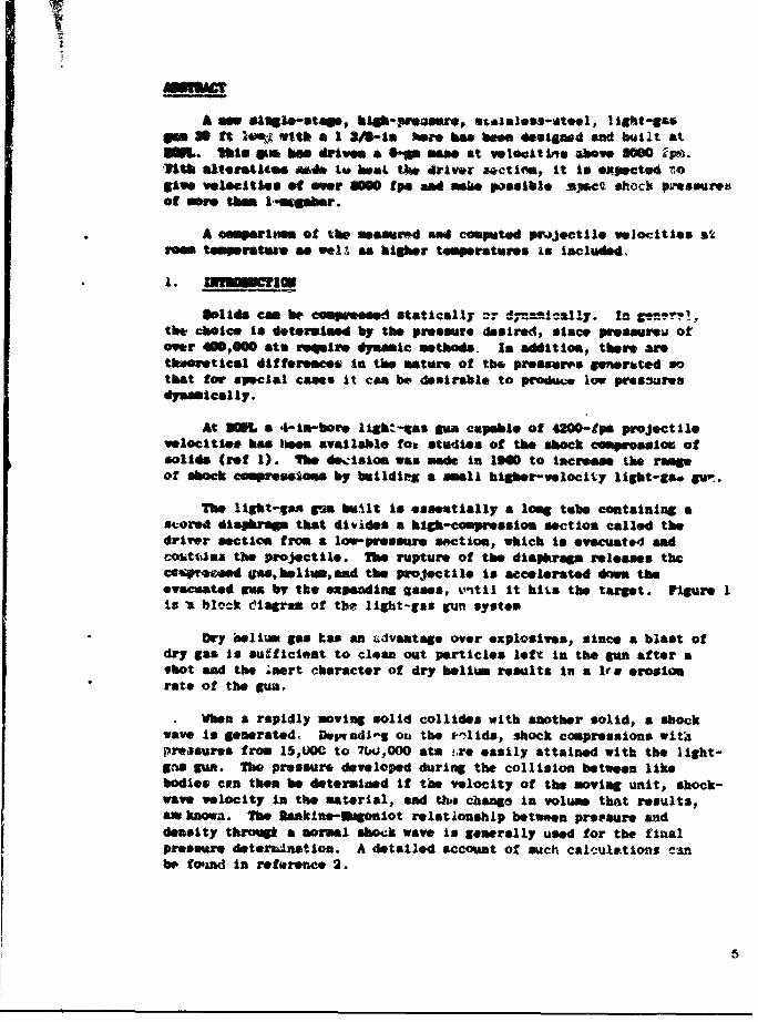
A m slouo-sts., hSb-Preg"-r, sI.isLiss-Otoel, I gt-SaSam 30 ft l1i with a 1 3/0-Is %ere has beeseied and b it atUiSL. tbIs am les drives a p mam at veoitis oave 5000 SOW i.'At alteret1e ned IM4 U 1mM the driver actIM, It If expecte4 togive veloitles of er 00 fpe and mseie possible xWpcQ shock pressuresof see them 1 .sMebar.
A eemportims of the measured and computed ptmjvctile velocitias as
e temprsteae as well " higher temperatures Is included.
1. inmmLna.
o11d con be compe esed statically or d -.- oally. In gen."!,the choice is determimed by the pressure desired, since pressureoi ofor 400,000 atm rWquire dyanmic methods. In addition, there artheoretical differesces in the matre of the pressuref generated sothat tor special cases it can be desirable to produce low presnuresdymmically.
At 2M a 4-iar-bore light-as gum capeble of 4200-1ps projectI11velocities has 11sm available to stUdIOS of the shock compirsioc ofsolids (rot I). The decislon was nde In 1940 to Increase the rafngof shock czmpresloss by buildeg a small higber-velocity ligbt-go gu'.
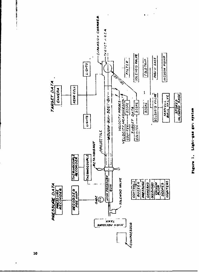
The liht-&As gua bilt is essentially a 1ong tube containing ascored 4iaphrg that divides a high-comprmession section called thedriver section from a low-pressure section, which t evacuate4 andcoit~oas the projectile. The rupture of the diapkrg releases theca rtozd Oas, hl v, and the projectile is accelerated d, theevacuated ows by the expanding uases, kintil it hits the target. figure 1is a block ciagram of the light-gas Sun system
Dry aelium Sas Las an dvatage over explosives, since a blast ofdry gas is sufficieat to clean out particles left in the gun after ashot and the ;aert character of dry helium results in a le erosionrate of the gun.
When a rapidly moving solid collides with s&other solid, a shockwave is generated. Dw,04J-$ on the *,lids, shock compressions witapreasurs from 15,kC to 7W,000 ato .,.re easily attained with the light-",s gun. The pressure developed during the collision between likebodies can then be determined it tks velocity of the moving unit, shock-wave velocity in the material, and th change in volume that results,aw knowa. The Makine-Iogoniot relationship betwen prtssure saddensity throqi a normal sbock wave is generally used for the finalpressure deterrAnation. A detalled account of such calculations cnbe fomd in reference 2.
5

he ecch i s &' O eneraud is a ftaction of t* maoerial impcteda" itti veleet7 I" v f~l Wiocity at the projectile in the light-gasgm is deItermr1d by t V 4 vim-prea w/pojectile-*elght ratio as.1*ieh the dSmPM*SA ruptursts. lue tai ratio as well as the choiceof mterial cowP is directly cotroll.od by the expeimater, thepr*sm genrated daring *my single test can be selected i advance.?hA, by the proper choice of the variablea, the final velocity of thepwoJectile and the resultant compressior can be controlled. The pres-
re In the impected material ,an W varied continuously from verymall values to pressures comp #ablit with those reached In metals bycontact explosives.
As a researck tool, the light-gas gun allows o" to bridge thepressures that bate been reportcd by various authors using staticpresses and those using dyn *ic compression. As a result, it is posaitleto cL*ck against the published data at both ends of the pressurespe-trolu.
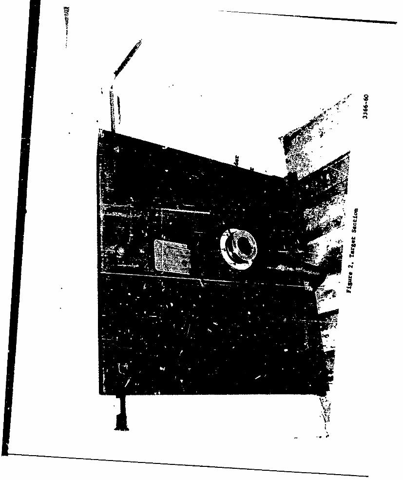
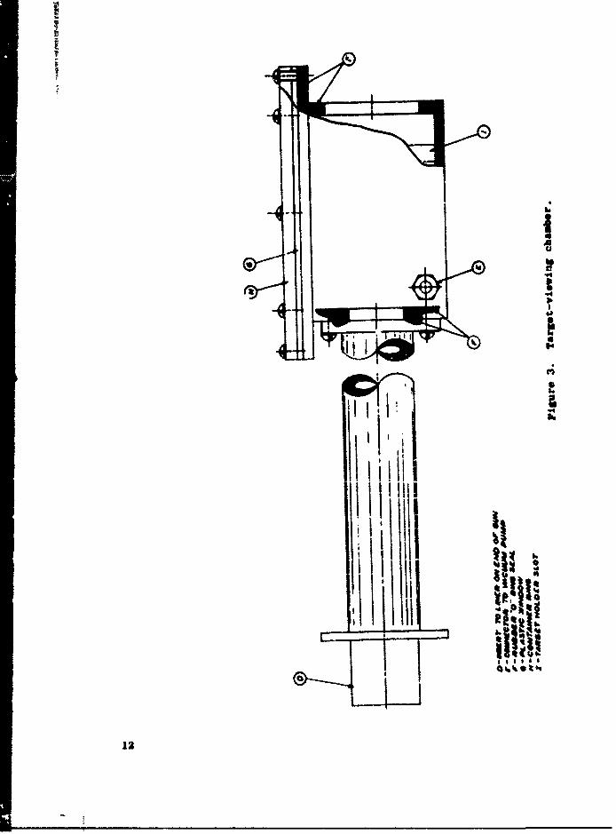
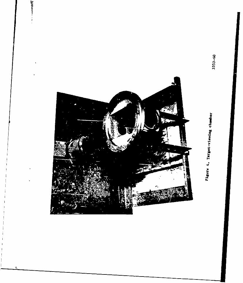
The projectile is continually guided %., n the gun until the LUpacttmk.s place, and as a rasult the alignment oV the projectile to thetarget .%urface c," be held to a fraction of a dogree re can expecterosion at the gun exit due to fragmentation of %Le tsrget holder, target"d projectile at impact. The gun exit contains a tempered..steel I-inerin a brass jection that can be .asily replaced if damaged. Figure 2sbws the rteel 1i er, target holder, and clamping system for the targetat -L: exit of th ,as gun. The exit sleeve diameter is 1/2 in. largervhan the bore of the gun nod thus allows for essentially free fligtt theinstaut before impact. Yho muzzle of the gun extends through a heavyreinforced wall into a cAteb diox rm,. To allow the impacts to be visi-ble and to occur it% a .,ontrolled ax.os here, when desired, an additional18-in. ection has been made thtmt can be attached instead of the nozzleexit sleeve. This section (fit 3 and 4) has a 4 x 4 x G-1n. visibleexpansion chauwber that can bo evacuated or filled with a particula" gasIsdependan.7 at a desired pressure.
The gun 7'-nttes Into a heaov metal catch box in the reinforcedconcrete rcc,, Nsignde to 1vl-"Itand the sudden over-pressure of the driv-ing gas .nd e tai1n the frmgavnts and shocks produced by an impact. Thscatcb box roos a,% an oxhaust fan to remove the gaseous products of theimpact, it also has viewing o:.t3 cut Ino Its A-In. walls te allowcameras to be set up outside the catch b.,x rooa and wti) 1ale recordeof tbo events occurring at the target.
The light-ga6, kaa, couponvc*s of which are th-wn in figure3 5 and 6,5,s basically a 1 3a-in. oo.," %tainv?--steel pipe, 28 ft long with a 1/4 in.wall. The Su" Is dtvided tite tweo secti"'s at . dreech; one side, the
6

driver section, Ias ft long. The bigh-pressure, gas is contained ilkWhisematies by a eco!," diaphragm of 52-W34 aluminum, bold In a
meta ciomp sed sealed with ", ibber 0 rifgs. ?igjAres 7 sad 8 showthe diaebrogm, the clumping &actie ad the method of locking thebigh-pveeeulre unit to the rest of the g'an. jhe length or the high-prefter system was chosen to issure Mhat reflect loos from the backwall of the pressurived tube zould not reach the project 1 1* before Itemerged from the evacuat*4 section.
In as attempt to achieve optim flow characteri stics after thediapr~a rupture, the breech section, at the entrance to the evacuatedsection. ws contoured for 3/4 in. to allow space for the fokded partsof the ruptured diaphregm. The exact shape sad depth of the groovesInscribed on the diaphroge had to s selected and proved experimnatal-ly. Improper design would cause a throttling of the gas In this criticalarea.
The evacuated section of the (sun contains two velocity-detect lagports, which contain sealed mnagnetic probes mounted flush with theIside malls. Waese ports are 13 i. apart with thie last one 4 in.frem the Impact soe of the gun.
The fore section of thejun is evacuated by a rotary pump with aspee" 2f 4.5 I/nec at I x 10 ma Mg. The Inlet port to the vacuumsystem Is directly behiad ad below the last velocity 4etectu.r. IFrotb*e 6xit port on the gun the vacuum tubing goes through a mechanicalfilter (Its primary purpose is pro1vectIou to the solemtS& and vacuumpp from target nd projectile f, qpto); then throLgh a solenoidvalve to a toe section. One tube of the tee goes through anothersoloomd valve throg a manual ball valve to a Stok*s-NcLeood vacugSW; the other goes through a cold trap past a tap for the continouslymeasuring Pirani v#-.- Wage, then tou the vacuum pump,
* The total volume to be evacuated Is 15 1 as a result, the pumpingtime is limited owly by the type of vapors In the system. Is practice,ft is found that pressures of loe than A*~ x can be achieved In approxi-
* mately 15 six from a cold start, and this pressure can easily be maintainedfor the necessary 3 to 4 min after the Yocusm system is Isolated from thepump. This allows suff icient tine to pressurise the high-pressure chmersad rupture the di&Ahragu 'zithout losing the desir&d vacuum In the muzzle,end of the gun.
3. DIAAO
Privious tests at various installations confirmed at OM haveitwi icatW that machined scored surfpuco'; could be designed to rupture,ovealy and quIckl7 with little interference to the flow. By takin'aftsatage of the practical experience gained In doeigning a quick-o~wnin:,diapbragm at OM, It was possible to make scored 0.063-in. 523 34aluminum disks that would perform -a required. These disks were foundto be satisfaztory at Prossures from 1300 psi to 2000 pal.
7

Th imertia of the Sections Of the diaphragm (i.e. the taicknessof the diapkragm nd the geometry of the cuts), as well as the rigidity0? the material chosen, determine the time for a good design to opencomplotely (from !0 to 120 "hac).
t lowr pressures the petals did not fold back completely and thefinal volcctty of the projectile was reduced. The scored design chosenwas In the form of a cross witht incomplete arcs across the end of eacharm. Figure 9 shows the scored diaphragm before and after use. Nofragmentation was ever ebserveO during tests using this configuration.
4. OPMATION
The target assembly is installed In the muzzle sleeve with the0 ring seal In place. Figure 10 &hows the tzrget-retan~ng system.The catch box roam is closed and the warning sign Is placed over thedoor. The diaphragm and projectile are loaded at the breech and thegun Is seeled. The vacuum pump is now turned on. When Lim desiredvacuum Is reacbod, the solenoid that cuts of f the pump from the gunIs actuated and the alarm buzzer Is pressed. Immediately afterwards,high-pressure helium Is admitted to the breech side of the diaphragm.he moment of firing is governed by the rupture of the diaphragm, which
allows the highly compressed gas to flow, driving the projectilebefore it. The snound of the rupture Is the signal to allow the openvalve from the compressed gas storage tank to close. The iapect ofthe projectile on the target takas place a few milliseconds after therupture of the diaphragm.
'the dimensions of the gun bore are regular enough to allow theprojectile to be machined to close tolerances. For the light-geli gum,the prqjSctiiv ii& ̂ hql,iu eUL&I cyli14M;*y Wlos ,W,&igkt V-4S& from alow of 6 pr to a high of 50 gr, depending on the requirements of theexperimeat. The back edge of the projectile Is punched 0.010 In. deepat three places to form three little prongs 1200 apar~t which preventthe unit from sliding freely beyond the relieved area of the breech(fig 9). The sudden gas preoasire shears these prongs of f and drivesthe projectile down the gun. A 1-in. irojectle* has sufficient clear-awne between it and the gun bore to make possibl, a tilt of 10 min ofarc In its alignment In the gun. Actually, due to wall effects, onewould expect an even smaller degree of tilt of the projectile's majoraxis during flight. As a result, the Impact an~le --an be predeterminedwithin 10-min by the Initial position of the target plate.
a5. 130017 --MUS
The velocity of the projectile Is desterred as It pasns twoagoetic inductive probes I ft apart. The velocity thus determined isslightly less than the posbible velocity at I*pact, 4ince the projectileIs still accolerating after it passes the last probe. Bach probe isbasically a ceil of wire wound about a =mall permanent magnet; changesIn tk:) magnetic field flux Induce a voltage In the Coll. These p&i-kupshave tMe advantage of simplicity of operat on, req~uiring no amplifiers
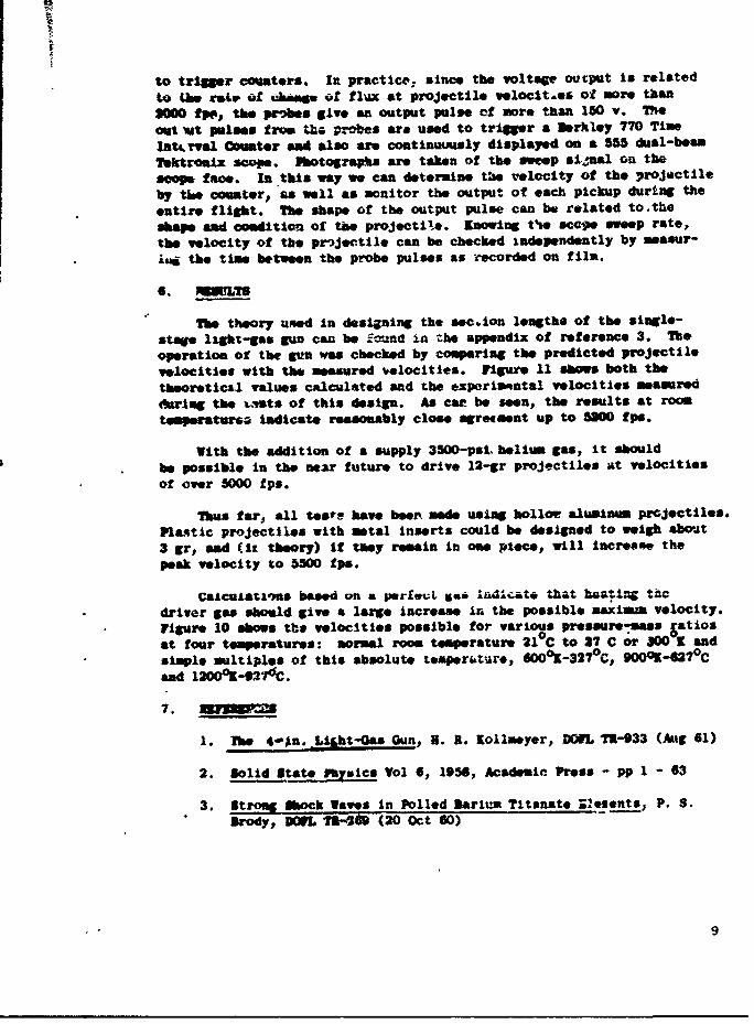
to triggr counters. In practice, since the voltage output is relatedto Uhe gair of Wummoe of fl-x at projectile velocit.es ot more than300 tpp, the probes give an output pulse ef nore than 150 v. 7%eout vAt pulses from tho, probes are used to trigger a Berkley 770 TimeInt.rval Counter and also are continuuusly displayed on a 555 dual-bernTektreftx scope. Pbotograhu are taken of the sweep a1jua1 on thescope fame. In this way we can determine the velocity of the projectileby tse counter.. as well as monitor the output of each pickup during theentire flight. The shape of the output pulse can be related to theshape and condition- of the projectite. Knowing t'se sccpe sweep rate,the velocity of the projeectle* can be checked independently by masur-ia4 the time between the probe pulses as recorded on film.
6. ML
The theory usned in designing the sec~ion lengths of the single-stage light-gas gun can be fou.nd in the appendix of reference 3. The,operation of the gun was checked by comparing the predicted projectilevelocities with the measured velocities. Figure 11 abos both thetheoretictal values calculated and the experimontal velocities measured01rIng the i.,sts of this design. As car be seen, the results at roteperatura* Indicate reasonably close agresiment up to 510 fps.
With the addition of a supply 3500-psi. heliim gas, it shouldbe possible In the near future to drive 12-gr projectiles at velocitiesof over 5000 fps.
Thus far, all teas have boon~ made using hollow aluminam prcjectiles.Plastic projectiles with metal Inserts could be designed to weigh abwut3 gr, and (ix. theory) if they remain in one piece, will incresee thepeak velocity to 5500 fps.
Calcukatl~ns based on a perfauL sai 1"dlcat* th"4t hga,"ng tftC* driver gas should give a large increase in the possible naximum velocity.
Figure 10 abos the velocities possible for various pressure-mass Satiosat four temperatures: normal roo temperature 210 C to 27 C or 300 K and
* simple multiples of this absolute tesperuturo, 600*K-327cC, 9000K-62? 0 Cand 120 0 K4-27dC.
7. i3
1. Th 44.Lgt-Gas Gun, R. R. Kollmeyer, DOOL IR-933 (Ang 61)
2. Solid State Fbysics Vol 6, 1956, Academic Press - pp I - 63
3. Strong Shock Waves In Polled barium Titanste 22esnts, P. S.IrdDML T1346 (20 Oct 60)
9
'I
(4U
i . .- .......
"- 1 " '
IK ll I
'4'D
10
Ii
/AI S
4~~
-- 4~
i
I
IA
U.S
tS~
'''IL, h.
~ ~ II Ii~
~ ~nUI
hi ~II iicz~ r I
12
2
S..6
SD
USD
$4U
14
'I$4
I
I <(\j2
Co-
64U
0
4.
lii
kK 15
i
if,
a
0
U
C"4a
'4U
USski
U'4
CIjk~
-4

0*0
0
S
UC
U
U
U
w.4
.4U'a'ILe
A.U
.4
0
k
I0
-4 2-44JU
<«4-
0
U
4~ 0
I3d I4.
U-4f5 ,
0

'0
C-
-4
U0
6I
'4-4
-4
.2 a~
a 'af~4 a
$4
I*~
0-4
IU

:i~c £t S27t
too-
I ~9Z7
fiue1. *vr4VessCmptdpoecievlolis(eeu a)
20A
D!3TRIBUTION
Deprtm-nt o? the ArmyOffice of the Chief of OrdnanceThe Pentagon, Washington 25, D. C.
ttn: ORM (Nuclear & Special Components Br)Attn: CWIfS, Joseph Kaufman
Director, Army Research OfficeOffice of the Chief of Research & DevelopmentDepartment of the ArmyWashington 25, D. C.
Conmandlg OfficerPicatinny ArsenalDover, New Jersey
Att.; F~t, sas Raia'i h & Ingineering LaboratoriesAttn: Library
Commanding OfficerU.S. Army Signal Research & Development LaboratoryFort Monmouth, New Jersey
Attn: Tech Library
Commanding General
Aberdeen Proving Gro4nd, MarylandAttn: ILL-1. J. RichelbergerAttn: George 1. Nauver
Commanding Officer
U.S. Army, Office of Ordnance Research
Box CM, Duke StationDurham, North Caculina
Commanding GesieralEngineer Research & Development Laboratories
U.S. ArmyFort Belvoir, Virginia
Attn: Tech Documents Center
ComwwoerU.S. Naval Ordnmcc LAboratcryCorona, California
Attn: Documents Librarian
Attn: Kellmeyer, R.
CommanderU.S. Naval Ordns"ce LaboraLuryWhite Oak, Silver Spring 19, Maryland
Attn: 5.J. JacobsAttn: S. Drimer
D1RIWTI4N (Continued)
Departuent of the NavyBureau of Naval WeaponsWashington 25, D. C.
Attn: NJI-3, Tech Library
ComanderNa~val Reze~.rc- LaboratoryWashington 25, 2. C.
Attn: 0. IrwinAttn: Tech Library
ComanderArmed Services Technical Information AgencyArlington Hqll StationArlington 12, Virginia
Attn: t'IPOS (10 copies)
Sandia CorporationSandia BaseAlbuquerque, Now Mexico
Attn: G. AndersonAttn: F. NielsdnAttn: R. Grahn
.Los -Alamos Scientific LaboratoryLos Alamos, Now MexicoAttn: J VackerleeAttn: R. DuffAttn: S. MinshallAttn: A. I. Binder
lniversitv of CaliforniaRadiat ion LaboratoryLivermore, Cal I roria
Director, Stanford Research InstituteMuenlo Park, California
Attn: The Poulter Labornatori*9
Clevite Research Corp.Cleveland, Ohio
Attn: 5. JaffeAttn: D. Derlincourt
National Bureai' of StandardsMineral Products DivisionIndustrial hIklding
Attn: A.D. Franklin
DISTIUT ION (Cont inued)
National Bureau of Stfand-rdsThermodynsmics DivisionWest Bilding
Attn: U.S. Green
National Bureau of Standardsmechanics DivisionIndustrial Building
Attn: I. C. LloydAttn: L. K. Irwin
Internal Distribution
inman, W. S., Jr./1gvoy, R. W.Apstein, U./erw;n, N. L.fjuarino, P. A/Kalmus, H.P.Fong, L. B. C./Schwenk, C. C.
Rardin, C. D., Lab 100Norto , B. U., Lab 200Rotkin, I., Lab 300Landis, P. Z., Lab 400Hatcher, 3. D., Lab 500Flyer, I. N., La 00Campagna, J. N./Apolenis, C. J., Div 700DMast, A., Div 8O0
Franklin, P. J./Morsey. 3. F., Lab 900Barris, Fred, .30ftvles, It. Z., 310
Brody, P. S., 310 (20 copies)Kinzelman, G. W., 320Piper, W., 320Ravitakyj U, 3io
Warren, a., 310
Curchack, H., 310Seaton, J. W., 260Morn, Leon, 310Technical Information Office, 010 (10 copics)Technical heports Unit/800 (3 copies)DW'L Library (5 copies)
(Two pages of abstract cards follow.)

S- I ! - - 1I
1 Ij li
I 'I ' :ii i:! ' ii i A II 1 13
• I jj " I i "U"' .I! , t~ It iI i
I I
Ii:.'
SI till :,.jititj I 11!i l~il
I I- I ,
alI ' s ' I
s,I 'm - -1 - . i~ . i.
Related Documents