Object-Oriented Development and The Unified Modeling Language UML Department of Computer Science Kent State University

Welcome message from author
This document is posted to help you gain knowledge. Please leave a comment to let me know what you think about it! Share it to your friends and learn new things together.
Transcript

Object-Oriented Development and
The Unified Modeling Language UML
Department of Computer Science Kent State University

J. Maletic Kent State University 2
UML Part I
• Introduction to UML • Overview and Background

J. Maletic Kent State University 3
Objectives of UML
• UML is a general purpose notation that is used to
• visualize, • specify, • construct, and • document
the artifacts of a software systems.

J. Maletic Kent State University 4
Background
• UML is the result of an effort to simplify and consolidate the large number of OO development methods and notations
• Main groups: Booch [91], Rumbaugh [91], Jacobson [92]
• Object Management Group – www.omg.org

J. Maletic Kent State University 5
Types of Diagrams
• Structural Diagrams – focus on static aspects of the software system – Class, Object, Component, Deployment
• Behavioral Diagrams – focus on dynamic aspects of the software system – Use-case, Interaction, State Chart, Activity

J. Maletic Kent State University 6
Structural Diagrams
• Class Diagram – set of classes and their relationships. Describes interface to the class (set of operations describing services)
• Object Diagram – set of objects (class instances) and their relationships
• Component Diagram – logical groupings of elements and their relationships
• Deployment Diagram - set of computational resources (nodes) that host each component.

J. Maletic Kent State University 7
Behavioral Diagram
• Use Case Diagram – high-level behaviors of the system, user goals, external entities: actors
• Sequence Diagram – focus on time ordering of messages
• Collaboration Diagram – focus on structural organization of objects and messages
• State Chart Diagram – event driven state changes of system
• Activity Diagram – flow of control between activities

J. Maletic Kent State University 8
Analysis & Design Process • Requirements elicitation – High level capture of user/
system requirements – Use Case Diagram
• Identify major objects and relationships – Object and class diagrams
• Create scenarios of usage – Class, Sequence and Collaboration diagrams
• Generalize scenarios to describe behavior – Class, State and Activity Diagrams
• Refine and add implementation details – Component and Deployment Diagrams

J. Maletic Kent State University 9
UML Driven Process
Requirements Elicitation Analysis Specification Design Implementation
Object Diagram SequenceDiagram
Use CaseDiagram State Chart Deployment
Diagram
CollaborationDiagram
ActivityDiagram
Class Diagram

J. Maletic Kent State University 10
RequirementsElicitation
Use CaseDiagrams
Validate
Analysis
Object Diagram
SequenceDiagrams
Validate
Design
ClassDiagram
State ChartDiagrams
Validate
UML Driven Process Model

J. Maletic Kent State University 11
Work Products
• Functional Model – Use Case diagrams • Analysis Object Model – simple object/
class diagram • Dynamic Model – State and Sequence
diagrams • Object Design Model – Class diagrams • Implementation Model – Deployment, and
Activity diagrams
J. Maletic Kent State University 12
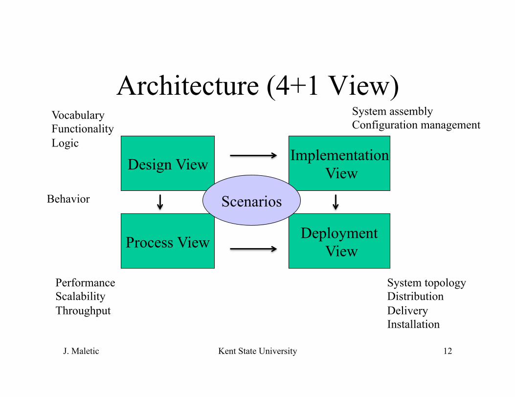
Architecture (4+1 View)
Design View
Process View Deployment View
Implementation View
Scenarios Behavior
Vocabulary Functionality Logic
Performance Scalability Throughput
System assembly Configuration management
System topology Distribution Delivery Installation

4+1 and UML
• Scenarios – Use cases • Design View – Class and sequence diagrams • Process View – Activity diagrams • Implementation View – Component diagrams • Development View – Deployment diagrams
• Kruchten, IEEE Software 12(6), pp. 42-50, 1995
J. Maletic Kent State University 13

J. Maletic Kent State University 14
Models of OO Analysis and Design
Class structure Object structure
Module architecture Process architecture
Dynamic Model
Static Model
Logical Model
Physical Model

J. Maletic Kent State University 15
UML Part II
• Modeling Requirements • Use Cases • Scenarios
J. Maletic Kent State University 16
Use Case Diagrams
• Describes a set of sequences. • Each sequence represents the interactions of
things outside the system (actors) with the system itself (and key abstractions)
• Use cases represent the functional requirements of the system (non-functional requirements must be given elsewhere)

J. Maletic Kent State University 17
Use case
• Each use case has a descriptive name • Describes what a system does but not how it
does it. • Use case names must be unique within a
given package • Examples: withdraw money, process loan
A Use Case

J. Maletic Kent State University 18
Actor
• Actors have a name • An actor is a set of roles that users of use
cases play when interacting with the system • They are external entities • They may be external an system or DB • Examples: Customer, Loan officer
An Actor
J. Maletic Kent State University 19
What is a Use Case
• Use case captures some user-visible functionality
• Granularity of functionality depends on the level of detail in your model
• Each use case achieves a discrete goal for the user
• Use Cases are generated through requirements elicitation

J. Maletic Kent State University 20
Goals vs. Interaction
• Goals – something the user wants to achieve – Format a document – Ensure consistent formatting of two documents
• Interaction – things the user does to achieve the goal – Define a style – Change a style – Copy a style from one doc to the next

J. Maletic Kent State University 21
Developing Use Cases
• Understand what the system must do – capture the goals
• Understand how the user must interact to achieve the goals – capture user interactions
• Identify sequences of user interactions • Start with goals and refine into interactions

J. Maletic Kent State University 22
Example
Buy Item
Log in
Refund a Purchase
CustomerCashier
Point of Sale Terminal

J. Maletic Kent State University 23
Refining Use Cases
• Separate internal and external issues • Describe flow of events in text, clearly
enough for customer to understand – Main flow of events – Exceptional flow of events
• Show common behaviors with includes • Describe extensions and exceptions with
extends

J. Maletic Kent State University 24
Extend and Include
User
Select an Option
Change Time or Date
Display Hightestand Lowest
Clock
«include»
«include»
Invalid Date«extends»

J. Maletic Kent State University 25
System Boundary
Buy Item
Refund a Purchase
Customer
Store
*
*
*
*

J. Maletic Kent State University 26
Use Case – Buy Item
• Actors: Customer (initiator), Cashier • Type: Primary • Description: The costumer arrives at the
checkout with items to purchase. Cashier records purchases and collects payment. Customer leaves with items

J. Maletic Kent State University 27
Example (generalization)
Perform CardTransaction
Manage CustomerAccount
ReconcileTransaction
Process CustomerBills
Credit Card Validation
Retail Institution
Finacial Institution
Customer
Corporate Custumer
Individual Custumer
«inherits»
«inherits»

J. Maletic Kent State University 28
Example: Weather Monitoring Station
• This system shall provide automatic monitoring of various weather conditions. Specifically, it must measure: – wind speed and direction – temperature – barometric pressure – humidity
• The system shall also proved the following derived measurements: – wind chill – dew point temperature – temperature trend – barometric pressure trend

J. Maletic Kent State University 29
Weather Monitoring System Requirements
• The system shall have the means of determining the current time and date so that it can report the highest and lowest values for any of the four primary measurements during the previous 24 hour period.
• The system shall have a display that continuously indicates all eight primary and derived measurements, as well as current time and date.
• Through he use of a keypad the user may direct the system to display the 24 hour low or high of any one primary measurement, with the time of the reported value.
• The system shall allow the user to calibrate its sensors against known values, and set the current time and date.

J. Maletic Kent State University 30
Hardware Requirements • Use a single board computer (486?) • Time and date are supplied by an on-board clock accessible via
memory mapped I/O • Temperature, barometric pressure, and humidity are measured by on
board circuits with remote sensors. • Wind direction and speed are measure from a boom encompassing a
wind vane (16 directions) and cups (which advance a counter every revolution)
• User input is provided through an off the shelf keypad, managed by onboard circuit supplying audible feed back for each key press.
• Display is off the self LCD with a simple set of graphics primitives. • An onboard timer interrupts the computer every 1/60 second.

J. Maletic Kent State University 31
Display and Keypad • LCDDisplay – Values and current system state (Running, Calibrating,
Selecting, Mode) – Operations: drawtext, drawline, drawcircle, settextsize, settextstyle,
setpensize • Keypad allows user input and interaction
– Operations: last key pressed – Attributes: key
Date: Time: Temp: Pressure: Humidity:
N
S
E W
Temp Hum Press
Wind Time Date Select Cal Mode

J. Maletic Kent State University 32
Use Diagrams
User
Clock
Sensor
Turn System on/off
Calibrate Sensor
Set Time/Date
Set TemperatureUnits
Display Highestand Lowest
Weather Station

J. Maletic Kent State University 33
Scenario: Powering Up 1. Power is turned on 2. Each sensor is constructed 3. User input buffer is initialized 4. Static elements of display are drawn 5. Sampling of sensors is initialized The past high/low values of each primary measurement is set to the value
and time of their first sample. The temperature and Pressure trends are flat. The input manager is in the Running state

J. Maletic Kent State University 34
Scenario: Setting Time and Date 1. User presses Select key 2. System displays selecting 3. User presses any one of the keys Time or Date. Any other key is
ignored except Run 4. System flashes the corresponding label 5. Users presses Up or Down to change date or time. 6. Control passes back to step 3 or 5 User may press Run to abandon the operation.

J. Maletic Kent State University 35
Scenario: Display highest and lowest 1. User presses Select key 2. System displays selecting 3. User presses any one of the keys (Wind, Temp, Humidity, Pressure).
Any other key is ignored except Run 4. System flashes the corresponding label 5. Users presses Up or Down to select display of highest or lowest in
24 hour period. Any other key press is ignored except for Run 6. System displays value with time of occurrence 7. Control passes back to step 3 or 5 User may press Run to abandon the operation.

J. Maletic Kent State University 36
Use Diagrams
User
Select an Option
Change Time or Date
Display Hightestand Lowest
Clock
«include»
«include»

J. Maletic Kent State University 37
Summary
• A well structured use case: – Names a single identifiable and reasonably
atomic behavior of the system – Factors common behavior by pulling such
behavior from other use cases that include it – Factors variants by pushing such behavior into
other uses cases that extend it – Describes events clearly – Described in a minimal set of scenarios

J. Maletic Kent State University 38
UML Part III
• Object Oriented Analysis • Classes & Objects • Class Diagrams

J. Maletic Kent State University 39
From Requirements to Analysis
• From the Use Case diagrams an initial set of objects and classes can be identified
• This is the first step of analysis • The second step is to refine the use cases
through interaction diagrams • Class diagrams and the object oriented
paradigm will be covered first

J. Maletic Kent State University 40
Objects
• An object has a state, behavior and identity. • The structure and behavior of similar objects are
defined in their class. • Terms instance and object are interchangeable. • State – the properties of an object and the current
values of these properties • Behavior – how an object acts and reacts in terms
of its state change and message passing

J. Maletic Kent State University 41
Objects and Classes
• Class – a generalization of a set of entities with common structure, behavior, and relationships to other classes. An abstract data type. – A person, an employee
• Object – an instance of a class. It has a state, value, and scope of existence – Joe Smith, Jane Doe
J. Maletic Kent State University 42
What is a good Class?
• Should provide a crisp abstraction of something from the problem (or solution) domain
• Embody a small well defined set of responsibilities and carry them out well
• Provides clear separation of abstraction, specification, and implementation
• Is understandable and simple yet extendable and adaptable.

J. Maletic Kent State University 43
Object Oriented Decomposition
• Identifying objects which derived from the vocabulary of the problem (and solution) domain.
• Algorithmic view highlights the ordering of events
• OO view emphasizes the agents that either cause action or are the subject upon which the actions operate.

J. Maletic Kent State University 44
Object Oriented Paradigm
• OO Analysis – A method of analysis which examines requirements from the perspective of classes and objects found in the vocabulary of the problem domain
• OO Design – A method of design encompassing the process of object oriented decomposition.
• OO programming – A method of implementation in which programs are organized as cooperative collections of objects, each an instance of a class whose members are part of a inheritance hierarchy

J. Maletic Kent State University 45
Object Model
• Abstraction – separate behavior from implementation • Encapsulation – separate interface from implementation • Modularity – high cohesion and low coupling • Hierarchy – Inheritance • Polymorphism – dynamic variable binding • Typing – strong enforcement • Concurrency – active vs. inactive • Persistence – existence transcends runtime

J. Maletic Kent State University 46
Types of Objects
• Boundary – represent the interactions between the system and actors
• Control – represent the tasks that are performed by the user and supported by the system
• Entity – represent the persistent information tracked by the system
• See [Jacobson ’99]

J. Maletic Kent State University 47
A Class in UML
+print()
-name : string(idl)-age : int
PersonClass name
Attributes
Operators

J. Maletic Kent State University 48
An Object in UML
object name and class joe : Person

J. Maletic Kent State University 49
Class Relationships in UML
• Generalization • Dependency • Association
• These can represent inheritance, using, aggregation, etc.
-Role1
*
-Role2
0..1

J. Maletic Kent State University 50
Example class diagram
+open()+close()+display()
-name : string(idl)window
dialogboxconsolewindow
event
control

J. Maletic Kent State University 51
Association
• Structural relationship between peer classes (or objects).
• Association can have a name and direction, or be bi-directional
• Role names for each end of the association • Multiplicity of the relationship

J. Maletic Kent State University 52
Examples of Association
person company
person company
Works For
-employee
1..*
-employer
*

J. Maletic Kent State University 53
Aggregation
• Special type of association • Part of relationship • Can use roles and multiplicity
university department
1 *

J. Maletic Kent State University 54
Link Attributes
• Associations may have properties in the same manner as objects/classes.
• Salary and job title can be represented as
person company
-salary-title
1..*
-employee
*
-employer
J. Maletic Kent State University 55
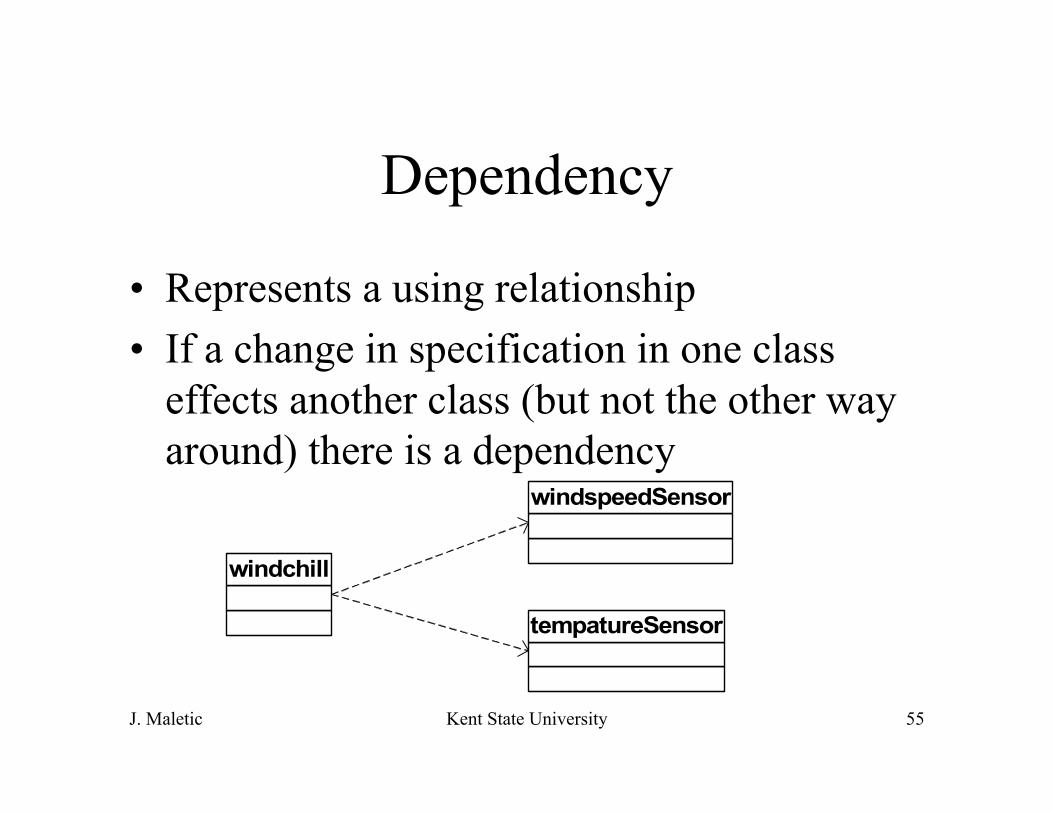
Dependency
• Represents a using relationship • If a change in specification in one class
effects another class (but not the other way around) there is a dependency
windchill
windspeedSensor
tempatureSensor

J. Maletic Kent State University 56
Generalization Sensor
+currentValue()+calibrate()
CalibratingSensor
+currentDirection()
WindDirectionSensor
+resetHighest()+resetLowest()
-highestValue-lowestVale
HistoricalSensor
-trendTrendSensor
+currentHumidity()-humidityHumiditySensor
+currentSpeed()-speedWindspeedSensor
+currentTemp()-tempTemperatureSensor
+currentPressure()-pressure
Barometer
• An is-a relationship • Abstract class

J. Maletic Kent State University 57
Which Relation is Right?
• Aggregation – aka is-part-of, is-made-of, contains
• Use association when specific (persistent) objects have multiple relationships (e.g., there is only one Bill Gates at MS)
• Use dependency when working with static objects, or if there is only one instance
• Do not confuse part-of with is-a

J. Maletic Kent State University 58
Object Modeling
• Given the high-level requirements (use cases) • Define the object model
– Identify objects – Compile a data dictionary – Identify association and aggregations – Identify attributes of objects – Generalize objects into classes – Organized and abstract using inheritance – Iterate and refine model – Group classes into modules/components

J. Maletic Kent State University 59
Example: Weather Monitoring Station
• This system shall provide automatic monitoring of various weather conditions. Specifically, it must measure: – wind speed and direction – temperature – barometric pressure – humidity
• The system shall also proved the following derived measurements: – wind chill – dew point temperature – temperature trend – barometric pressure trend
J. Maletic Kent State University 60
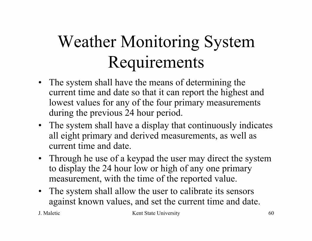
Weather Monitoring System Requirements
• The system shall have the means of determining the current time and date so that it can report the highest and lowest values for any of the four primary measurements during the previous 24 hour period.
• The system shall have a display that continuously indicates all eight primary and derived measurements, as well as current time and date.
• Through he use of a keypad the user may direct the system to display the 24 hour low or high of any one primary measurement, with the time of the reported value.
• The system shall allow the user to calibrate its sensors against known values, and set the current time and date.

J. Maletic Kent State University 61
Use Diagrams
User
Clock
Sensor
Turn System on/off
Calibrate Sensor
Set Time/Date
Set TemperatureUnits
Display Highestand Lowest
Weather Station

J. Maletic Kent State University 62
Identify Objects
• From the vocabulary of the domain • User, clock, sensor, temperature, LCDDisplay,
Keypad, time, date, wind speed, humidity, barometer, calibrator, metric units, English units, input manager, sensor sampler, wind direction, display manager, trend, pressure, current time, current date, current temp, high temp, low temp, change temp, change time, power up, power down, input buffer, trend, key, running, selecting

J. Maletic Kent State University 63
Eliminate Terms
• Refine the model by eliminating • Redundancy – classes that represent same concept • Irrelevant classes – things you don’t care about • Vague classes – ill defined boundaries • Attributes – describe parts of objects • Operators – sequence of actions are often
mistaken for classes • Roles – what it is not the role it plays • Implementation details – save it for later

J. Maletic Kent State University 64
New Data Dictionary
• Time & Date • Sensors: Temperature, Pressure, Humidity, Wind Speed,
Wind Direction • Keypad • Input Manager • Display (LCD Device) • Display Manager • Timer (clock) • Sensor Sampler

J. Maletic Kent State University 65
Relationships
LCDDevice
displayManager
sampler
+currentTemp()-tempTop Package::TemperatureSensor
+currentDirection()
Top Package::WindDirectionSensor
+currentSpeed()-speedTop Package::WindspeedSensor
+currentHumidity()-humidityTop Package::HumiditySensor
+currentPressure()-pressureTop Package::Barometer
1
1
1
1
111
1
1
1

J. Maletic Kent State University 66
Relationships
sensors
samplerinputManager
displayManager
«interface»keypad
«interface»LCDDevice «interface»
timer
-time-date
timeDate
windChill
1
1
1
1
1
1
11
1
1
dewPoint
windDirection
sensor1
1
1
1
1
1..*
1
1

J. Maletic Kent State University 67
UML Part IV
• Modeling Behavior • Interaction Diagrams • State Chart Diagrams • Activity Diagrams

J. Maletic Kent State University 68
Refining the Object Model
• Typically, only very simplistic object models can be directly derived from use cases.
• A better understanding of the behavior of each use case is necessary (i.e., analysis)
• Use interaction diagrams to specify and detail the behavior of use cases
• This helps to identify and refine key abstractions and relationships
• Operations, attributes, and messages are also identified during this process

J. Maletic Kent State University 69
Interaction Diagrams • There is one (or more) Interaction diagram per use case
– Represent a sequence of interactions – Made up of objects, links, and messages
• Sequence diagrams – Models flow of control by time ordering – Emphasizes passing messages wrt time – Shows simple iteration and branching
• Collaboration diagrams – Models flow of control by organization – Structural relationships among instances in the interaction – Shows complex iteration and branching

J. Maletic Kent State University 70
Sequence Diagrams
• X-axis is objects – Object that initiates interaction is left most – Object to the right are increasingly more subordinate
• Y-axis is time – Messages sent and received are ordered by time
• Object life lines represent the existence over a period of time
• Activation (double line) is the execution of the procedure.
J. Maletic Kent State University 71
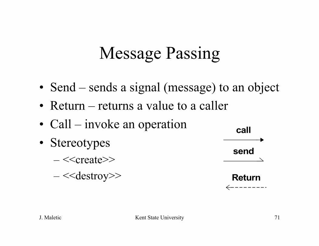
Message Passing
• Send – sends a signal (message) to an object • Return – returns a value to a caller • Call – invoke an operation • Stereotypes
– <<create>> – <<destroy>>
call
send
Return

J. Maletic Kent State University 72
Example UML Sequence Diagram
c:client p:planningAssistant
:TicketAgent<<create>>
setItinerary(i)
calculateRoute()
route
<<destroy>>
notify()

J. Maletic Kent State University 73
Example S : sampler WD : sensors WS : sensors Temp : sensors Hum : sensors
Every 1/60 sec.
Every 0.5 sec.
Every 5 min.

J. Maletic Kent State University 74
S:Caller :swtich R:Caller
c:converse
liftReceiver
setDialtone
dialDigit(d)
routeCall(S,R)
<<CREATE>>
ring
liftReceiver
connect
connectconnect
J. Maletic Kent State University 75
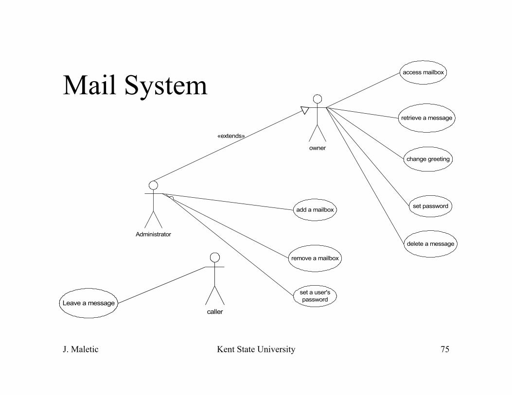
Mail System
owner
Administrator
access mailbox
retrieve a message
change greeting
set password
delete a message
add a mailbox
remove a mailbox
set a user'spassword
«extends»
Leave a messagecaller

J. Maletic Kent State University 76
Mail System (2)
owner
retrieve a message
delete a message
«uses»
caller
Leave a message
Reach an extension
«uses»

J. Maletic Kent State University 77
Mail System Objects
• Caller, owner, administrator • Mailbox, extension, password, greeting • Message, message list • Mail system • Input reader/device

J. Maletic Kent State University 78
Access Mailbox
: owner
: mailboxrecorder : inputReader
ext : extension
sys
ext:=getExtension()
verifyExtension
lookup(ext:extension)
checkForInput
dial(dddd)
promptForExtension
Notify
dial(8888)
create()
J. Maletic Kent State University 79
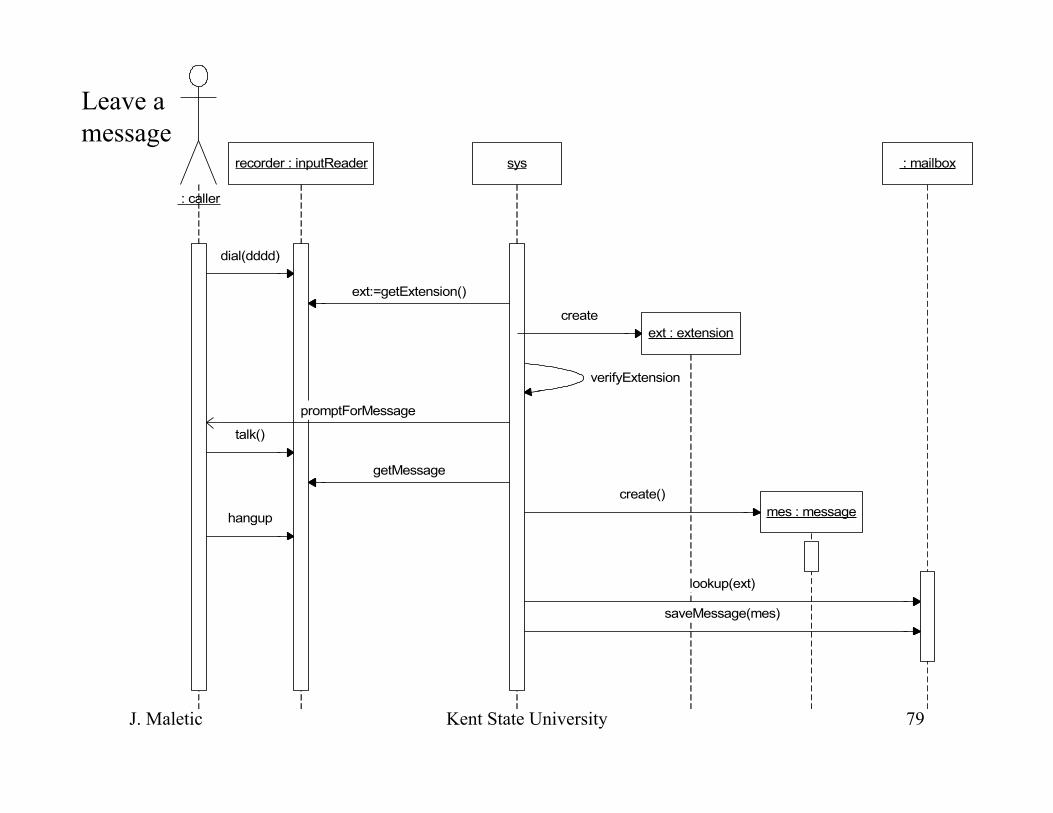
Leave a message
: caller
: mailbox
mes : message
recorder : inputReader
ext : extension
sys
ext:=getExtension()
verifyExtension
getMessage
lookup(ext)
saveMessage(mes)
dial(dddd)
hangup
create
talk()
create()
promptForMessage

J. Maletic Kent State University 80
+verifyExtension()-promptForExtension()-promptForMessage()-notifyDone()
MailSystem
adminMailbox
+lookup(in mailbox : extension)+saveMessage(in mess : message)
mailbox
+getExtension() : extension+getMessage() : message+dial()+hangup()+checkForInput()+talk()
inputReader
messageList
+create()
message
1
2
1
*
1
-Administrator1
1-Users*
+create()
extension
1 1

J. Maletic Kent State University 81
Properties of Sequence Diagrams
• Initiator is leftmost object (boundary object) • Next is typically a control object • Then comes entity objects

J. Maletic Kent State University 82
Collaboration Diagrams
• Emphasizes the organization of the objects that participate in an interaction
• Classifier roles • Association • Messages, flow, and sequencing

J. Maletic Kent State University 83
Example Collaboration Diagram
orderTaker TicketDB
CreditBureau
Request(order, customer) 2: cost:=researce(order)
1: checkCredit(customer)
3: debit(customercost)

J. Maletic Kent State University 84
Leave a Message
inputReader
mailbox
MailSystem
1: dial3: dial6: talk
2: checkforInput()4: ext:=getExtension()
7: mess:=getMessage()
5: Lookup(ext)
8: save(mess)

J. Maletic Kent State University 85
Collaboration vs Sequence
• The two diagrams really show the same information
• Collaboration diagrams show more static structure (however, class diagrams are better at this)
• Sequence diagrams clearly highlight the orderings and very useful for multi-tasking
J. Maletic Kent State University 86
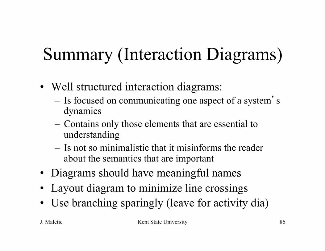
Summary (Interaction Diagrams)
• Well structured interaction diagrams: – Is focused on communicating one aspect of a system’s
dynamics – Contains only those elements that are essential to
understanding – Is not so minimalistic that it misinforms the reader
about the semantics that are important • Diagrams should have meaningful names • Layout diagram to minimize line crossings • Use branching sparingly (leave for activity dia)

J. Maletic Kent State University 87
State Diagrams
• Finite state machines (i.e., automata, Mealy/Moore, state transition)
• Used to describe the behavior of one object (or sometimes an operator) for a number of scenarios that affect the object
• They are not good for showing interaction between objects (use interaction diagrams)
• Only use when the behavior of a object is complex and more detail is needed

J. Maletic Kent State University 88
State Diagram Features
• Event – something that happens at a specific point – Alarm goes off
• Condition – something that has a duration – Alarm is on – Fuel level is low
• State – an abstraction of the attributes and relationships of an object (or system) – The fuel tank is in a too low level when the fuel level is
below level x for n seconds

J. Maletic Kent State University 89
Example: on/off Switch
on off
/ FlipSwitch
/ FlipSwitch
J. Maletic Kent State University 90
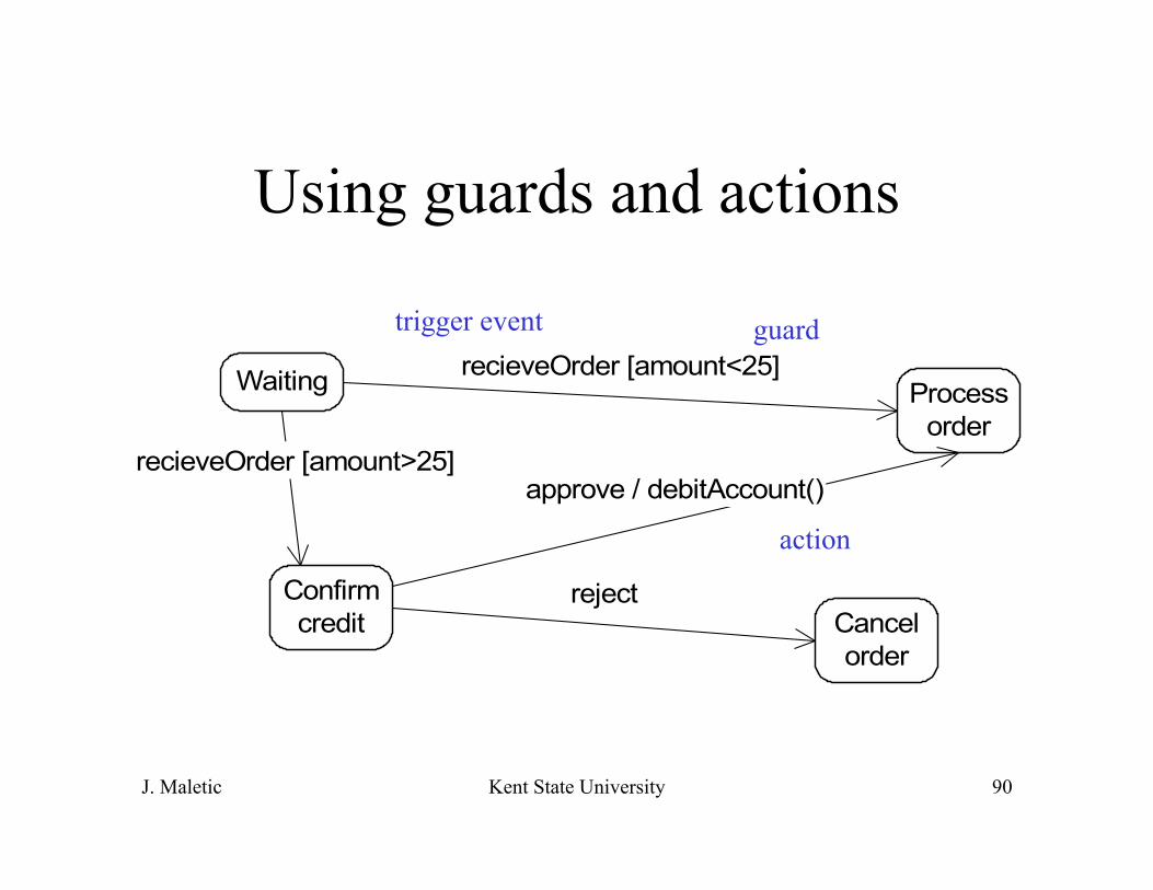
Using guards and actions
Waiting
Confirmcredit Cancel
order
Processorder
recieveOrder [amount<25]
recieveOrder [amount>25]approve / debitAccount()
reject
trigger event guard
action
J. Maletic Kent State University 91
Activity Diagrams
• Special form of a state machine (flow chart) – intended to model computations and workflows
• States of the executing the computation not the states of an object
• Flow between activity states is caused by the end of a computation rather then an event

J. Maletic Kent State University 92
Why Activity Diagrams
• Flowcharts (abet a bit glorified) are not very amiable to OO
• Not part of any previous notations • Suitable for modeling the business activities • OO and UML is becoming very prevalent in
business applications • Introduced to help sell products?

J. Maletic Kent State University 93
Example (from Mail System) Get Extension
Access Mailbox
Retrieve messages Change Greeeting Change password
Enter new greeting enter new passwordDisplay current message

J. Maletic Kent State University 94
UML Part V
• Implementation Diagrams • Component diagrams • Deployment diagrams
J. Maletic Kent State University 95
Component Diagrams
• A component is a physical thing that conforms to and realizes a set of interfaces
• Bridge between logical and physical models • Can represent object libraries, COM components,
Java Beans, etc. • Classes represent logical abstractions, components
represent physical things that reside on a node (machine).
• Components are reachable only through interface

J. Maletic Kent State University 96
Examples
Transactions
«table»AccountATM-GUI
Update
spell-checksynonymsDictionaryadd-new-word

J. Maletic Kent State University 97
Mail System
Mail SystemInputReader
Mailbox AdminMailbox

J. Maletic Kent State University 98
Deployment Diagrams
• Nodes are physical elements that represent a computational resource (machine)
• Association between nodes • Components are allocated to nodes (one or more) • Components represent the physical packaging of
logical elements • Nodes represent the physical deployment of
components

J. Maletic Kent State University 99
Example
BankServer
ATMKiosk
-Server*
-Client*

J. Maletic Kent State University 100
With Components BankServer
ATMKiosk
-server1
-client*
ATM-GUI
Transactions«table»Account
Update

J. Maletic Kent State University 101
Weather Station Clock
Computer
LCDDisplay
Keypad
WindDirectionSensor
WindSpeedSensor
TempatureSensor Humidity
Sensor Barometer

J. Maletic Kent State University 102
Modeling Source Code
Mailbox.cpp
Mailbox.h
Mailsystem.cpp
Inputreader.h
Related Documents