GROUP MEMBERS Nabeel Jamil Muhammad Sayam Bilawal Saeed

Welcome message from author
This document is posted to help you gain knowledge. Please leave a comment to let me know what you think about it! Share it to your friends and learn new things together.
Transcript

GROUP MEMBERS
Nabeel Jamil
Muhammad Sayam
Bilawal Saeed

INTRODUCTION TO SOFTWARE ENGINEERING
UML
HISTORY OF UML In early stages of model driven development
there was a great need for some universal approach for modeling a software system
As different people understand the notation in different way if there is no universal model approach
At that time brooch, rumba, Jacobson gave there theories and universally accepted
All of three decided to build a notation language by merging all of three language and out product of that was UML (unified modeling language )
HISTORY OF UML In 1997 OMG (Object management group) a
non profit organization standardized the UML
Since then they are making improvement in UML
Released versions of UML 1.1 November 1997 1.2 July 1998 1.3 March 2000 Latest >> 2.4.1 August 2011

INTRO.. UML UML stands for Unified Modeling Language
The Art of Software Modeling
The UML represents a collection of best engineering practices that have proven successful in the modeling of large and complex systems.
Standard language for specifying, visualizing, constructing, and documenting the artifacts of software systems, business modeling and other non-software systems.

INTO. CONT… The UML is a very important part of
developing object oriented software and the software development process.
Using the UML helps project teams communicate, explore potential designs, and validate the architectural design of the software.
UML is a notation system though which we can visualize a model of a system
IMPORTANCE OF SOFTWARE MODEL If software is complex need of model If a system is developed by the hundreds
of People there is also need of model for smooth communication and understanding the software system
mange complexity in design build and design architecture Visualize the implementation Design secure , scalable, robust and
extendable system

UML TYPES UML is divided in to two General set of
Diagrams
Structured modeling diagrams (It shows the static view of the model)
Behavioral modeling diagram (Behavior diagrams shows the varieties of interface within a model as it 'executes' over time)
STRUCTURAL MODELING DIAGRAM
Class Diagram Object Diagram Component Diagram Package Diagram Composite Structure Deployment Diagram

BEHAVIORAL MODELING DIAGRAM
Use Case Diagram Activity Diagram State Machine Diagram
Interaction DiagramCommunication DiagramSequence DiagramTiming Diagram Interaction Over view Diagram

UML DIAGRAM HIERARCHY

STRUCTURAL MODELING
DIAGRAM
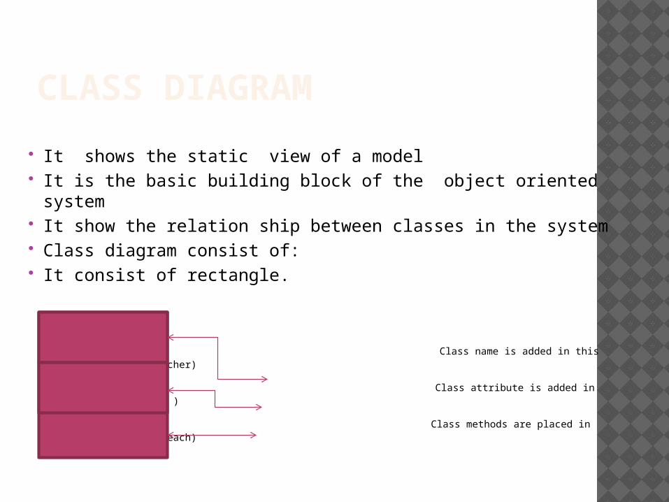
CLASS DIAGRAM
It shows the static view of a model It is the basic building block of the object oriented
system It show the relation ship between classes in the system Class diagram consist of: It consist of rectangle.
Class name is added in this this compartment (teacher)
Class attribute is added in this department (name )
Class methods are placed in this compartments (teach)

CLASS DIAGRAM + sign with attributes or methods shows class
member are public - sign with attribute or methods shows class
members are private
Class name is added in this this compartment (teacher)
Class attribute is added in this department (-name
Class methods are placed in this compartments (+teach)

Sis class diagram
Login
+username+password
+Login()+validation()+get_data()+display()
Student details
+Name+Address+Age+Course+Department+Phone no
+get_data()+Display()
Update details
+Student details+Result details
+Updae_info()+get_detail()+Display()

OBJECT DIAGRAM An object diagram may be considered a
special case of a class diagram Object diagrams highlight the
relationship between classes at some point in time
Object is shown by a rectangular with classifier name in the center of rectangular and under line
Object diagram shows complex relationship between classes
It is useful if we feel classes as more abstract

OBJECT DIAGRAM

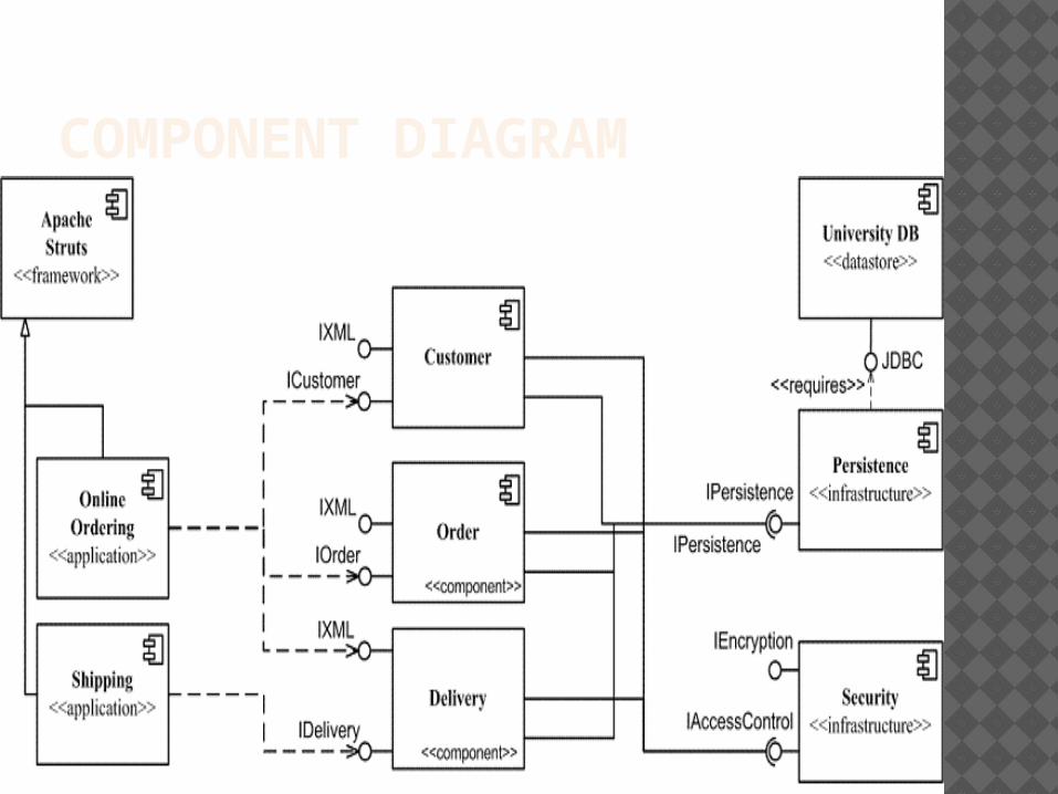
COMPONENT DIAGRAMUML component diagrams shows the
dependencies among software components, including the classifiers that specify them (for example implementation classes) and the object that implement them; such as source code files, binary code files, executable files, scripts and tables.
COMPONENT DIAGRAM

BEHAVIORALMODELING
DIAGRAM
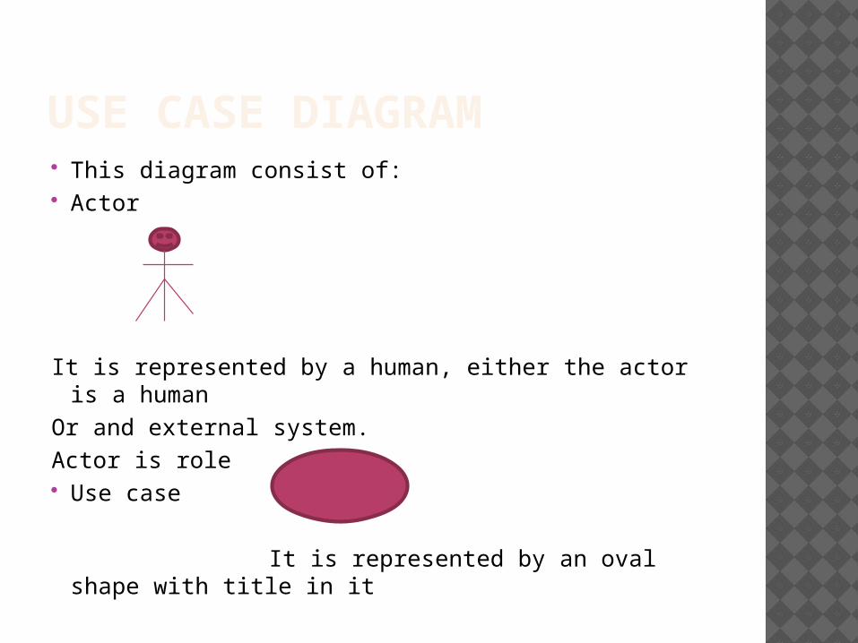
USE CASE DIAGRAM This diagram consist of: Actor
It is represented by a human, either the actor is a human
Or and external system.Actor is role Use case
It is represented by an oval shape with title in it

USE CASE DIAGRAM USE CASE diagram have relationship It is relationship between a use case to
another use case In which a include use case in necessary to
perform other use case,
for example in place order every time the check funds is included to complete the place order
place order(use case) <include >
(check funds) use case
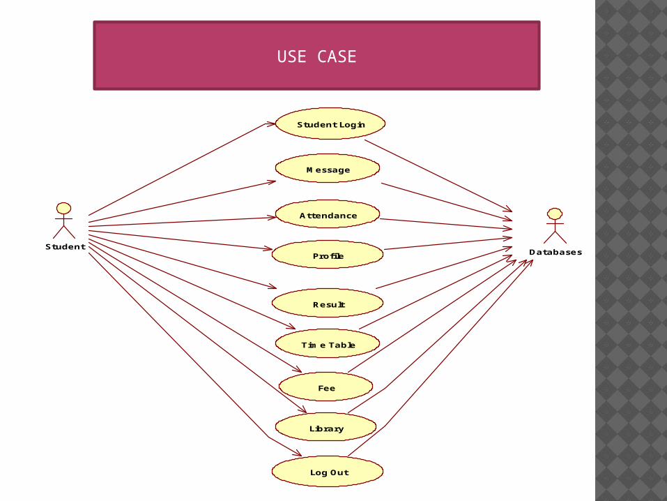
StudentDatabases
Student Login
Message
Attendance
Profile
Result
Time Table
Fee
Library
Log Out
USE CASE

ACTIVITY DIAGRAM Activity diagram is also dynamic view of
the system Activity diagram similar to flow charts Each activity consist of series of actions Actions are represented by oval shapes Actions are connected by arrows Arrow shows the flow of the activity
diagram Activity diagram also shows decision
points called decision node

ACTIVITY DIAGRAM Activity diagram is used to describe the
individual use case Use case is used to describe the user
goal Activity diagram can be used where we
can use flow charts

ACTIVITY DIAGRAMLogin
Student Registration
back to registration
Select Course
Profile
Result
Fee
Library
Log Out
If No
Yes

INTERACTION OVERVIEW All the same controls from activity
diagrams (fork, join, merge, etc.)
Controls can be used on interaction overview diagrams to put the control logic around the lower level diagrams.

INTERACTION OVERVIEW DIAGRAM

ANY QUESTION ?? If ( no ){ Cout << “ Thank you “;}
Related Documents