MASTER OF SCIENCE IN ENGINEERING PHYSICS UPTEC F02 086 MASTER’S THESIS NOVEMBER 2002 UML FOR EMBEDDED SOFTWARE DEVELOPMENT: AN EVALUATION OF RHAPSODY IN C MAGNUS LUNDQVIST E-MAIL: [email protected]

Welcome message from author
This document is posted to help you gain knowledge. Please leave a comment to let me know what you think about it! Share it to your friends and learn new things together.
Transcript

MASTER OF SCIENCE IN ENGINEERING PHYSICS UPTEC F02 086 MASTER’S THESIS NOVEMBER 2002
UML FOR EMBEDDED SOFTWARE DEVELOPMENT:
AN EVALUATION OF RHAPSODY IN C
MAGNUS LUNDQVIST
E-MAIL: [email protected]


Engineering Physics Programme Uppsala University, School of Engineering
UPTEC F 02 086 Date of issue
November 2002
Author Lundqvist, Magnus
Title UML for Embedded Software Development: An Evaluation of Rhapsody in C
Abstract The Unified Modeling Language (UML) has developed into a de facto standard for object-oriented software modeling. Its popularity is also growing for real-time and embedded systems, although the modeling of important aspects of this field has not yet been standardized.
In this master’s thesis, an evaluation of the UML-based software development tool Rhapsody was performed for the Hitachi H8S/2238 micro-controller. Rhapsody is delivered with support for a number of embedded operating systems, but no operating system was used for the H8S.
The evaluation was divided into a number of domains, each of which were examined within two case studies. The code generated from the UML models could be compiled and executed on the micro-controller after some modifications and with the use of a particular NoOS framework.
Rhapsody, or an equivalent UML modeling tool, is recommended for embedded software development for two reasons. Firstly, positive results were found during the evaluation and secondly, the two case studies could be completed in a short time. It should, however, be noted that Rhapsody is not yet a completely mature tool, as there are a few improvements to be desired from future versions.
Keywords UML, software development, Rhapsody, object-oriented, embedded, real-time
Supervisor(s) Bengtsson, Anders
Examiner Pettersson, Paul
Project name
Sponsors Styrex AB
Language English
Security
ISSN 1401-5757
Pages 67
Supplementary bibliographical information
School of Engineering, Studies Office Phone: +46-(0)18-4713003 Visiting address: Lägerhyddsvägen 1, The Ångström laboratory, Uppsala Fax: +46-(0)18-4713000 Postal address: Box 536, SE-751 21 Uppsala, Sweden E-mail: [email protected]

1
Contents
1. Introduction ...........................................................................................................2 1.1. Overview of UML ..................................................................................................... 3 1.2. Overview of Rhapsody.............................................................................................. 5
2. Method of Evaluation.............................................................................................7 2.1. Evaluation Domains.................................................................................................. 7 2.2. Approach of Evaluation............................................................................................ 7
2.2.1. Project Initiation............................................................................................................... 8 2.2.2. Description of Case Study A............................................................................................. 8 2.2.3. Description of Case Study B ............................................................................................. 9
3. Project Initiation ..................................................................................................10 3.1. Generating Executable Code for Target Environment.......................................... 10
3.1.1. Integrating Driver Code and Rhapsody-generated Code................................................... 10 3.1.2. Running Compiler and Linker from within Rhapsody...................................................... 11
3.2. Graphical User Interface for Development Environment ..................................... 12 3.3. System Interface ..................................................................................................... 12
4. Case Study A: Game Application .........................................................................14 4.1. UML Model of the Application .............................................................................. 14 4.2. Execution in the Development Environment ......................................................... 14 4.3. Execution on the Hardware.................................................................................... 15 4.4. Animated Sequence Diagrams................................................................................ 16
5. Case Study B: Communication Protocol ..............................................................18 5.1. Protocol Description ............................................................................................... 18 5.2. UML Model of the Protocol.................................................................................... 18 5.3. Execution in Development Environment ............................................................... 19 5.4. Execution on the Hardware.................................................................................... 19
6. Evaluation Results ...............................................................................................21 6.1. Evaluation of Analysis and Design ......................................................................... 21
6.1.1. Analysis and Design Process........................................................................................... 21 6.1.2. Real-time Properties ....................................................................................................... 22 6.1.3. Early Prototype............................................................................................................... 22
6.2. Evaluation of Implementation ................................................................................ 23 6.2.1. Forward Engineering ...................................................................................................... 23 6.2.2. Reverse Engineering....................................................................................................... 24 6.2.3. Roundtrip Engineering.................................................................................................... 25 6.2.4. Memory Usage ............................................................................................................... 26
6.3. Evaluation of Program Testing .............................................................................. 26 6.3.1. Testing in Development Environment ............................................................................. 26 6.3.2. Testing in Target Environment........................................................................................ 27
6.4. Evaluation of Documentation ................................................................................. 27 6.4.1. Rhapsody Reporter with Text Documents ....................................................................... 27 6.4.2. Rhapsody Reporter with HTML...................................................................................... 28 6.4.3. Rhapsody Reporter Pro ................................................................................................... 28 6.4.4. Report on Model Tool .................................................................................................... 28
6.5. Evaluation of Compatibility ................................................................................... 29 6.5.1. Rhapsody in Relation to the UML Specification.............................................................. 29 6.5.2. Integration with other UML Development Tools ............................................................. 29 6.5.3. Integration with non-UML Development Tools ............................................................... 30
7. Conclusions..........................................................................................................31 8. Acknowledgement ................................................................................................32 9. References ............................................................................................................33 Appendix A: Documentation of Case Study A......................................................... 34 Appendix B: Documentation of Case Study B......................................................... 50

2
1. Introduction Development of large and complex software systems, especially real-time or embedded ones, is a difficult task. Good methods to counter the challenges are not always obvious at first sight. As stated by D’Souza and Willis [1], “Software development continues to be, as always, a difficult and fascinating mixture of art, science, black magic, engineering, and hype.” In this context, relevant development processes and tools are required to finish projects successfully, on time and within budget.
The Unified Modeling Language, UML [2], is widely used for modeling software and has become a de facto industry standard [3]. Its usage has recently expanded into real-time and embedded development. This thesis is the result of a master’s degree project made to investigate if a UML tool would also be useful for embedded software development. The project was carried out at the embedded systems development company Styrex in Uppsala. The tool that was chosen for the study is called Rhapsody in C (version 3.0.1), made by the US company I-Logix [4].
Creating a system model (or model for short), before starting to write code for a complex software system is sometimes compared to making a blueprint before starting to work on a new building. Even for a very small program, the developer hopefully has given some thought as to how he is going to solve the problem at hand, before he actually starts writing source code in some computer language. This could be said to be a model that exists only in the head of the developer.
UML gives the ability to visualize this model through the use of nine standardized diagrams. An important cornerstone of UML is object-oriented design. This gives better modularity of the software and improves the possibility of reuse, if used correctly.
The use of UML (or other modeling methods) enables the model to move from ideas in the developer’s head to a formal but still rather intuitive model. This should help the developer to specify his thoughts in a precise manner. Now since other people may also view the model, it should hopefully increase their understanding of the system as well. This could facilitate the discussion within the development team and between the customer and the developers.
If this is true, a UML tool should make it possible to shorten the time from the initial specification to the actual completion and documentation of a software project. This requires that the tool makes it possible to take full advantage of the modeling capabilities offered by UML. But more importantly and sometimes easily forgotten, UML is no magic spell, which will miraculously solve all challenges faced by the software industry. Just like any other tool, for instance a hammer, UML may be used in clever ways, which make the task at hand a lot simpler. But if used incorrectly it may give no benefits or introduce new problems.
This project is targeted at a particular embedded environment, but it is hoped that many of the results achieved should also be applicable to other similar embedded systems. The particular target environment is a Hitachi H8S/2238 micro-controller. Some additional components were added in a previous project, of which a display, a keyboard and a serial fiber modem will be used here. Source code for device drivers are present at the beginning of the project, and will be referred to as driver code in this report.
There is an excessive amount of scientific papers describing system modeling with UML in general. There are also numerous specifically concerned with embedded or

3
real-time UML modeling. Despite a thorough search, very few scientific articles were found where Rhapsody in particular was studied. In the article “Rhapsody: A Complete Life-Cycle Model-Based Development System” [5], an overview of Rhapsody’s capabilities is given. It should be read with more than the normal scientific skepticism though, since it is sponsored by I-Logix themselves. Two project reports from case studies were found on the internet [6] [7], written by university students.
The rest of this thesis is organized as follows: Chapter 1 gives short overviews of UML and Rhapsody. Chapter 2 contains is a description of how the evaluation is divided into domains. Two case studies are defined to gather information for the evaluation. Chapter 3 describes how the development and target environments are initiated. A description of the work on case study A, a simple game, follows in Chapter 4. The next chapter describes the development of case study B, a communication protocol. Chapter 6 is a discussion of the tool in the light of the evaluation domains specified in Chapter 2 and Chapter 7 summarizes the report.
1.1. Overview of UML This is only meant as a short introduction to the Unified Modeling Language (UML), so that the further discussion in the report may be followed. For the complete specification of the current version UML 1.4, please refer to the OMG specification [2]. The next release will be version 1.5, and work has also started on the major update UML 2.0.
The Unified Modeling Language (UML) is a graphical language for visualizing, specifying, constructing and documenting the artifacts of a software-intensive system [2]. The visualization is made with diagrams containing graphical objects and text. The system is well specified, since the syntax and notations of the diagrams are standardized. The semantic is not rigorously defined though; it exists only as textual descriptions. Outside the scope of UML, the diagrams may be used to generate source code in different programming languages, as is done in for example the Rhapsody tool.
One of UML’s greatest advantages and also disadvantages is that it is a general-purpose language. Due to UML’s success as a modeling language, its usage expands into new technical and scientific fields. Even though the language provides many powerful modeling techniques, there is always the need for more abilities in some particular field, as for instance real-time. On the other hand, the aim of the UML developers has always been to keep the language as small as possible, to keep it general. A possible solution to this conflict of interests is provided by UML itself in the form of extensibility mechanisms. These enable for a user (but more useful to a group of users) to add new modeling capabilities by using stereotypes, tagged values and constraints. These may be used to define language extensions, called UML-profiles.
It is possible to keep UML general, since it focuses only on the software. No assumptions are made concerning which programming language or operating system that should be used. The underlying hardware is described very briefly in the deployment view (see below). All this means that the software system may be described in detail, but still allows it to be implemented in different programming languages and on different platforms.
UML is not a new invention; it is rather a blend of techniques such as Booch [8], OMT [9] and OOSE [10]. Initially, the three men behind these techniques also headed the development of UML. They were Grady Booch, James Rumbaugh and Ivar

4
Jacobson, also known as the “Three Amigos”. The aim of the developers was to keep the modeling language as simple as possible, so many rarely used features were removed. The UML of today is rather comprehensive despite these efforts, but also supports a wide range of views on a software system. The UML diagrams and their respective key concepts are listed in Table 1 [11]. Diagram Important concepts Use case diagram Use case, actor, association Class and object diagram Class, object, association, generalization, dependency,
interface, realization Statechart diagram Intra-object behavior, state, event, transition, trigger,
guard, action, substate, superstate Activity diagram State, event, transition, action, fork, synchronization Sequence diagram Inter-object behavior, message, object, system border Collaboration diagram Inter-object behavior, message, object, actor Component diagram Component, dependency, interface, realization Deployment diagram Node, component
Table 1 UML diagrams and important concepts
Use case diagrams describe the different abilities of the system as seen from an actor, a human or machine user of the system. This diagram is often the first one used, to describe the big overall picture of the system.
For structural description, class and object diagrams are used. They rely much on concepts from object oriented design and it should be fairly straightforward to generate code for an object-oriented language such as C++ or Java. The visualization of class diagrams in turn, originate from the Entity-Relationship diagrams [12].
The behavioral aspects are modeled with statechart, activity, sequence and collaboration diagrams. These aspects are not naturally integrated in object-oriented languages. Statecharts are based on the work of Harel [13]. They describe which state an object is currently in and how the object may enter other states via different transitions, possibly as a response to events received from other parts of the system. Activity diagrams are quite closely related to statecharts, but rather describe an algorithm that is not necessarily associated to an object. Sequence diagrams originate from message sequence charts [14] and describe the chronological order of messages sent between objects. Collaboration diagrams also describe the messages sent between different objects, but the focus here lies on the structure, showing which objects that have associations between them. Sequence and collaboration diagrams may be used to describe a possible scenario of a use case.
The transition from model to code is not really the focus of UML, but there are two rather basic diagrams describing the implementation phase. The component diagram describes how the different parts of the model are assigned to different components, corresponding to for example software libraries or executables. Deployment diagrams describe basic hardware structure and how the components are spread over different nodes.
As described above, the hardware-software interaction or timing properties is not the focus of UML and thus little help is given when modeling time, concurrency, or shared resources. Efforts have been made to incorporate these aspects into the object-oriented paradigm, most noticeably with ROOM, Real-time Object Oriented Modeling [15]. The companies Rational Software Corporation and ObjecTime Ltd. integrated ROOM as a profile in UML, creating the UML-RT profile [16]. This is not an official

5
standard though; the OMG is currently working on a “UML Profile for Schedulability, Performance and Time” [17]. This would hopefully enable for example standardized schedulability analysis by external tools.
There is a wide range of UML-tools on the market. Tools especially targeted at embedded or real-time systems include Real-time Studio (ARTiSAN) [18], Rational Rose RealTime (Rational) [19] and Rhapsody (I-Logix) [4]. Since there is yet no standard considering timing properties, these are handled differently in different tools; with UML constraints in Real-time Studio and with so called properties in Rhapsody.
1.2. Overview of Rhapsody Some basic properties of Rhapsody need to be clarified before reading this report. For a complete description of the tool, please refer to the online help. Some diagrams are connected to a particular class (see below), but the following model elements may be used on the global project level:
• collaboration diagrams • component diagrams • object model diagrams (similar to class diagrams) • sequence diagrams • use case diagrams • packages • components
As in the UML standard, all model elements defined in a diagram such as functions, classes or use-cases have a package to which they belong. All the information present in the diagrams is also present and modifiable in the packages. This means that it is possible to build a model by only modifying the packages, but this would take away much of the UML’s advantage, to have a graphical representation of the model.
Each executable file or library that the tool may generate is represented by a component. It has a scope indicating which packages it should compile. External files, not generated by Rhapsody, may also be included in the component and they can optionally be compiled together with the rest. There are also settings, the most important ones concern operating system of the target, instrumentation (see below), include files and switches to compiler and linker. Each component normally has its own directory in the file system to which source code, object files and executables are generated.
UML has a unified syntax for all diagrams, but at first sight it is not obvious how different diagrams are related to each other [3]. In Rhapsody, the diagrams are connected as follows. Statecharts must belong to a class, use case or actor. The same is true for activity diagrams, with one addition: they may also belong to an operation or function. No element may own both a statechart and an activity diagram. It is possible to associate a sequence diagram with one or several use cases. These relations are illustrated using UML notation in Figure 1.
The process of going from a system model to implementation code in some programming language is called forward engineering. In Rhapsody this is done automatically; code is generated from the UML model. The other way around is called reverse engineering. Old source code is analyzed and somehow integrated in the model. Roundtrip engineering is a combination of both the others. The development is done partly in the model and partly in the source code. Forward and reverse engineering are used to synchronize the model and code.

6
StateChart
ActivityDiagram
ActivityDiagram
StateChart
Class
ActivityDiagram
Operation
UseCaseSequenceDiagram
{Also applies toActor.}
0,1
0,1
0,1
*
0,1
0,1
**
{or}
{or}
Figure 1 Relations between model elements in Rhapsody
Obviously since Rhapsody in C is used, the source code generated with forward engineering contains no classes in the real sense of the word. Object_types, implemented as structs, are used instead. They quite closely resemble classes, but there are some differences. When calling an operation of an object, the syntax is
objType_oper(me, [arguments])
where objType is the object_type of the object, oper is the name of the operation, me is a pointer to the object and [arguments] is an optional list of arguments. Another difference is that the concept of inheritance is not supported for object_types.
Despite these differences, the term class will be used instead of object_type in this report. Object_types are actually intended to be as similar to objects as possible in the non-object-oriented language C. The object-oriented terminology is hopefully also familiar to the reader. When keeping the distinction between classes and object_types in mind, this will not make a big difference.
The generated code is based on the contents of the packages, which also reflect the diagrams as described above. The structure is thus automatically generated, involving for example how source files include each other. Behavior is translated into code for statecharts and activity diagrams associated directly to classes or actors, but not to functions. Implementation code written for functions or object methods are automatically placed in the source files. The sequence of messages in collaboration or sequence diagrams does not affect the code.
Rhapsody enables the program model to be executed and tested in the development environment. A kind of instrumentation referred to as design level debugging may be used. This means that the information from the debugging is related directly to the model instead of to the source code generated from it. Animation is an instrumentation, which enables the developer to follow events being sent, state transitions taken, and attributes changed in the model during execution of the generated program. Tracing is a form of textual instrumentation.
Properties may be set for the entire project down to individual model elements, such as components, classes or functions. They regulate how the notations of the model translate to code, how Rhapsody integrates with other programs and how the tool generally functions.

7
2. Method of Evaluation
2.1. Evaluation Domains The aim of this master’s thesis is to evaluate if Rhapsody is appropriate to use for the studied type of embedded systems or not. The focus is to find out if Rhapsody eases the software development compared to conventional source code programming. The tool is originally not intended for a micro-processor without operating systems, which will be used here.
To structure the evaluation, it is divided into a number of domains. The evaluation domains roughly correspond to the sequence of activities that should take place in an ideal software project. In addition, there are some domains concerning compatibility issues. The domains are listed in Table 2 and the result of the evaluation for each particular domain is given a section in Chapter 6.
Evaluation of analysis & design 1. Analysis and design process 2. Real-time properties 3. Early prototype Evaluation of implementation 1. Forward engineering 2. Reverse engineering 3. Roundtrip engineering 4. Memory usage Evaluation of program testing 1. Testing in development environment 2. Testing in target environment Evaluation of documentation 1. Rhapsody Reporter with text file 2. Rhapsody Reporter with HTML 3. Rhapsody Reporter Pro 4. Report on model tool Evaluation of compatibility 1. Rhapsody in relation to the UML specification 2. Integration with other UML development tools 3. Integration with non UML development tools
Table 2 Evaluation domains
2.2. Approach of Evaluation Chapters 4 and 5 contain descriptions of two case studies, which are carried out for the master’s thesis. This is done in order to gather facts and experience to evaluate the domains in the preceding section. Rhapsody is used in the case studies to create a system model, from which code is generated and executed on the target system.
The target environment, a Hitachi H8S/2238 micro-controller, has a 32-bit H8S/2000 central processing unit (CPU) running at 7.14 MHz, with no operating system. Memory is 16 KB RAM for variables and stack, as well as 256 KB flash memory for program binaries and constant variables. Additional components were added in a previous project to the micro-controller. There is a two-line display with 16

8
characters per line as well as a keyboard with 16 keys, both connected on the I/O-bus. In addition, a serial fiber modem may be connected to the H8S.
Development environment is Windows NT. Tools to be used in the project are: • Rhapsody in C version 3.0.1 by I-Logix • MakeApp version 3.21 by IAR Systems • Embedded Workbench by IAR Systems. User interface version 2.31C and target
descriptor version 1.52C/WIN. Including components: • C-compiler icch8 version 1.41D/W32 • Assembler ah8 version 1.40E/W32 • Linker xlink version 4.51T/386
• Microsoft Visual C++ version 6.0 • Microsoft Visual SourceSafe version 6.0a
The case studies to be carried out are a game application and a communication protocol. These are important to gather information for the master’s thesis. The case studies should be advanced enough to cover the evaluation domains. A project initiation is also necessary, as described in the next section.
2.2.1. Project Initiation Before the case studies may be started, the development tools must be properly set
up and integrated. This consists of the following three major steps. Generating executable code for target environment
There is a configurable framework in Rhapsody to adjust the tool to different operating systems (OS). This needs to be done for an OS-free system. The generated source code may have to be modified in order to work with the C-compiler icch8 in Embedded Workbench.
Graphical user interface for development environment The input from the H8S keyboard and the output to its display need to be simulated when running in the development environment. This could be done by letting the code from the UML model interact with the PC keyboard and a console window. But a more user-friendly way is to do it with a graphical user interface (GUI). Together with animation, this would provide good possibilities for debugging. A GUI also provides the possibility to demonstrate the behavior of the model in the development environment before it is implemented on the embedded system.
System interface The UML model will need a way of accessing hardware units such as keyboard, display and serial modem. Since the model will be the same for both development and target environment, a system interface must be defined to address this issue. The system interface for the development environment should communicate with the driver code or directly manipulate relevant registers. For the development environment, the interface should interact with the GUI described above.
The interface should be as general as possible with minimal amount of environment specific details. Firstly because it will make it easier to use, and secondly because it should be possible to transfer it to a similar embedded environment as the H8S without too many modifications.
2.2.2. Description of Case Study A A simple game with real-time properties is chosen as the first case study. During the analysis, design, implementation and documentation of this case study, answers to the majority of the evaluation domains are expected to be found.

9
Model of Application The game is modeled using object-oriented design and statecharts. The game accesses the hardware or the GUI simulator through the system interface described above.
Execution in the Development Environment For testing and debugging purposes, the GUI from the project initiation is used. Design-level debugging is used to verify that the model is correct, at least in the development environment.
Execution on the Hardware The source code generated from the program model will probably need some modification in order to fit the present hardware. Hopefully, many errors are found in the development environment, but tests will of course be necessary also on the hardware.
2.2.3. Description of Case Study B In this case study a UML model is made of the communication protocol SETCAD, which may be used as a communication channel between a micro-controller and a desktop computer. This will provide verification and elaboration of the previous case study.
Protocol Model The model of the protocol is made only on the micro-controller (H8S) side and not on the desktop machine. The model should provide functions for an application to reliably send and receive packets over a serial fiber modem. A hardware interrupt will be generated by the driver code when a byte is received and the UML-code has to be notified of this event. This case study will hence give knowledge on how Rhapsody may be used together with hardware interrupts.
Execution in the Development Environment As in the previous case study, animation is used in the NT environment to test the model. Although it is quite as straightforward in this case, since the communication protocol also involves a device on the other side and a hardware interrupt when a byte is received.
Execution on the Hardware To test the model on the target, a connection to a PC must be established over a serial fiber modem. A test program on the PC, which is able to communicate correctly using the SETCAD protocol, will be needed. This test program is not within the scope of the master’s thesis and should hopefully be provided and not have to be written.

10
3. Project Initiation This chapter describes how the project initiation is carried out. This involves compiling the generated code, making a GUI and a system interface.
3.1. Generating Executable Code for Target Environment
3.1.1. Integrating Driver Code and Rhapsody-generated Code The aim was to learn how to compile code generated by Rhapsody in Embedded Workbench together with the driver code. First a simple C program was made without UML to learn how to use the driver code and Embedded Workbench. The program writes to the display on the micro-controller by using the present driver code. The files and functions of the driver code starting with ma_ or MA_ are generated with the MakeApp tool and the rest are written by hand. The program executed correctly in the target environment.
The next step was to consider how to initialize UML and how to support specific features such as statecharts at run-time. It was found that for the supported target operating systems, Rhapsody is shipped with an Object execution framework (OXF), which is a run-time library needed by the generated code. A framework for a target environment without operating system had to be either found or written. Fortunately, it turned out that Dag Erlandsson at the Swedish Rhapsody-retailer Nohau had written such a framework. This was used in the project and will be referred to as the NoOS framework in this report. It was initially made for an Infineon 166 processor, which is rather similar to the H8S used in this project.
The framework is itself modeled in UML and the OXF is contained in a package called NoOSOXF. It is also necessary to modify some of Rhapsody’s project properties in the file siteC.prp. The NoOS framework handles:
• Triggered operations: synchronous communication between objects. • Reactive classes: a class that can react (take a transition) as a response to a
triggered operation. This means a class with either an associated statechart or activity diagram.
• Static heaps: implementation of a set. • Timeouts: triggers an event after a certain elapsed time. • Timer management: manages all timeouts using a static heap.
The framework was somewhat modified to fit the current processor as described below. Compared to the frameworks for operating systems supplied in Rhapsody, some features are missing. There is no support for threads or animation. Instead of asynchronous events, the synchronous triggered operations should be used to communicate between statecharts. Memory is allocated statically for timeouts occurring at run-time, each timeout takes 22 bytes. The number of possible timeouts was set to 20, which will be adequate for any small- to medium-sized application.
The generated source code for the framework (specification and implementation files) is about 60 KB or 2000 lines of code. Much of this is comments or Rhapsody-generated standard functions. For an examination of the size of the binary code for the framework, see Section 4.4.
A change in the project properties was done to be able to easier use the NoOS-framework. Previously only one framework could be active at a time, either the NoOS or the original one, and this was controlled outside Rhapsody by choosing between two different property files. But it was made possible to define different frameworks

11
for different components or configurations, as is the original thought in Rhapsody. A few properties have to be added manually when creating a new NoOS component, but this is done very rarely and the possibility of compiling for both development and target environment makes the tool easier to work with.
A UML-model for writing to the display was constructed and code was generated with Rhapsody. A few Infineon-specific things were removed from the application model. The files timer.h and timer.c were present both in the framework and in the driver code, so in driver code it was renamed to hwTimer.
The compiler in Embedded Workbench did however not accept forward struct declarations of the type struct structName;, where the actual definition of the struct is found later. This is accepted in ANSI C [20], so Rhapsody can hardly be held responsible for that. If the struct declarations were removed manually from the code, it was possible to compile it. But all of the code is regenerated by Rhapsody whenever a change is made and there were numerous struct declarations, so a way had to be found to remove them automatically. This was achieved by using the GNU-program grep and regular expressions. Since the file NoOSMake.bat is executed when choosing build in Rhapsody, the following call was added there:
for %%v in ("*.h") do grep -v -E -x struct[[:space:]][[:alnum:]_]+; %%v>%%v.temp
After that compiling and linking was successful. Reverse engineering was tried to avoid having to make all the changes again when the code was regenerated, but without success.
Another later discovered struct problem is caused by Rhapsody in its generated code. In some situations a vector of an incomplete type is declared, which is not allowed in ANSI C [20]. This is since incomplete type means that the memory size of the struct is unknown and thus it is not possible to know how much memory to allocate to the array. An example of this problem would be the code
struct A; struct A aa[10]; // Not allowed ! struct A { int x; int y; };
One possibility to make the code ANSI C is to move all variable declarations to after the definition of their respective struct. This is done by an external perl-script written by an I-Logix office in Germany. In the example above it would mean moving the incorrect row number two to the very last, after the struct definition.
3.1.2. Running Compiler and Linker from within Rhapsody To achieve a good environment for the developer, it is desirable to be able to compile and link directly from within Rhapsody. Then, it will not be necessary to start a separate compiler or linker. This was achieved by running the command-line versions of the c-compiler (icch8), assembler (ah8) and linker (xlink). Necessary changes in the NoOS framework were made to adapt Rhapsody to the external programs. This mostly consisted in finding command-line switches corresponding to project options in Embedded Workbench.
The driver code needed to be integrated and compiled together with the rest of the files. This was done by adding the files to the component in Rhapsody, and setting the properties so that they are included in the compiling process.

12
The compiler generates quite a few uninteresting warnings, so the –w switch is used to disable them. It is recommended to periodically remove this switch to search for more serious warnings. The assembler was easily set up since it was only needed to assemble one file. For the linker there are several switches specified in the h8sAdvancesSingle.xlc-file, controlling for example memory allocation.
Other switches control things as processor type and path to include files. Paths containing spaces must be written in the old MS-DOS style, with 8 characters. Another possibility is to set the environment variable C_INCLUDE for the compiler and XLINK_DFLTDIR for the linker. All object files are generated to the same subdirectory of the project, either .\debug\obj\ or .\release\obj\ , as would have been the case when running Embedded Workbench. The executable is placed in either .\debug\exe\ or .\release\exe\ respectively.
3.2. Graphical User Interface for Development Environment Input and output when the program runs on the micro-controller needs to be
simulated in the development environment. Input may be simulated using the event generator in Rhapsody, which generates events to the program while it is running. Using the printf command to write to an MS-DOS window may simulate output.
But it was interesting to the evaluation to see how much effort it would take to build a graphical user interface (GUI) and integrate it with the Rhapsody model. Visual Basic was first considered for making the GUI. Dag Erlandsson at Nohau was consulted and it turned out that making the GUI and UML-code communicate might involve some effort.
It was therefore decided to use Microsoft Visual C++ instead. The interface seemed easier and there were sample programs available with Rhapsody. From the application model, code is generated and a library is made in Rhapsody. The library is then linked with the GUI-program in Visual C++.
The GUI consists of 16 buttons and a two-line display, as is also the case on the real hardware. An event to simulate input may be sent to the Rhapsody model using the command
RiCGEN_BY_GUI( &targetObject, evName());
The GUI is periodically polling some variables from the UML model to handle model-output, which in this case means writing text on the display.
It was also desired to have the ability to compile and build the GUI directly from Rhapsody, especially since a change in the application would mean that the GUI had to be linked again to include the new library. This was achieved by including the source files from visual C++ in the component and modifying their properties.
3.3. System Interface The UML model must somehow access external hardware units; this is done through the system interface. One realization of the interface is needed for the H8S and one for the windows environment. In the case studies, they are compiled by the components SI_h8s_Lib and SI_win_Lib respectively (see Appendix 1 and 2). Since the interface is the same, it is possible to create the model independently of target environment.
The interface to the present driver code was found to be at quite a high level of abstraction. For example, there are functions for printing a string to the display, returning the currently pressed key on the keyboard, sending and receiving a byte on the serial modem as well as handling timers.

13
Because of this, there was no real need for an extra layer between the driver code and the Rhapsody-generated source code. So the interface between model and hardware was simply chosen at the level of function calls to the present driver code. The functions must have the same names, arguments and return types in both interfaces, so they may be treated equally by the environment-independent model.
The interface is for H8S was constructed by adding links to the needed files of the driver code to the SI_h8s_Lib component. The contents of the files are not included in the model, but they are compiled by Rhapsody. In order for the application to use the driver code, the desired specification files must by referenced by #include in the generated source files. Adding them as standard headers to the component achieves this. One thing to keep in mind about the driver code and hence also about the H8S system interface is that some initialization functions must be called before anything else is done.
The windows system interface was created using reverse engineering on the specification files of the driver code. This worked as expected, details may be found in the evaluation, Section 6.2.2. Because the specification files were used, all the function bodies were initially empty. The functions communicating with keyboard and display were written so that they communicate with GUI described in the previous section.

14
4. Case Study A: Game Application The first case study is a simple game. Below is a description of the game application, which could be a part of the project specification in a real-life project. The nouns are italic, since they are possible objects of the UML model, according to next section.
This is a game, where the player is to guard a bank. The bank has a number of doors, through which visitors enter the bank. Some of the visitors are customers with ordinary banking errands. Others are robbers who try to hold up the bank. The player has three lives at the start of the game and when all lives are gone, the game is over.
The player is armed and can shoot any of the visitors. If a customer enters the bank, he leaves after a few seconds and the player may not shoot him. If a robber enters, he may not be shot until he has waited a while and drawn his gun. When the robber has drawn his gun, the player must shoot him quickly or is otherwise shot himself by the robber.
The player interacts with the game via a keyboard and a display. On the display the doors are shown, which are sometimes opened by a visitor. The display also shows the score and the number of remaining lives. With the keyboard the player can start and abort the game and shoot at the visitors entering through the doors.
4.1. UML Model of the Application The nouns of the project description are listed in Table 3, which is used to identify possible objects, functions and attributes for the UML model. An automatically generated report of the case-study model may be found in Appendix 1.
Noun in project description Mapping to UML model Bank Not used Customer Object Display Functions (in the system interface) Door Object Errand Not used Game Object Gun States in the Robber statechart Keyboard Functions (in the system interface) Life Attribute of object (Game) Player Actor Robber Object Score Attribute of object (Game) Visitor Not used
Table 3 Mapping of project description nouns to a UML model
4.2. Execution in the Development Environment Code must be generated for the Microsoft environment in order to use instrumentation, hence the NoOS framework is not used.
To simulate input from the keyboard and output to the screen, the GUI from the project initiation was used (see Section 3.2). Animation was used at run-time to debug the application.
One possibility with animation is to follow how the attributes and variables change and to follow how the state machines change their states. First it was tried to use triggered operations from the GUI to communicate with the model, but the animation

15
did not work as expected. This was later reported to I-Logix. When using events from the GUI, it worked as expected. This part of the animation was a good help when debugging the application.
Another part of the animation is the possibility to let Rhapsody create animated sequence diagrams. This does not work quite as well though. Several problems were encountered during the work on this case study.
The first was that no way was found to introduce objects owned by other objects on the sequence diagram. For example, it was tried to put the object theGame.itsDoor[1].itsCustomer:Customer on the sequence diagram. If it is written on the instance line or dragged there from the browser, the text appears correctly at first. But if the sequence diagram is closed and reopened, the text has changed to itsCustomer:Customer. Since there is apparently no such object, it is also not animated if animated sequence diagrams are used.
Later when working with animated sequence diagrams, several new problems were found. These problems lead to that animated sequence diagrams provided no help to the case study. If these animated diagrams are to be used when debugging the design it must be possible to trust them, which turned out not to be possible. In order to describe the problems in more detail, a separate model was created, according to Section 4.4. The general evaluation of development environment testing may be found in Section 6.3.1.
4.3. Execution on the Hardware After the automatic modifications described in Section 3.1.1, there was no need to alter the program to make it execute on the micro-controller. The program behaved in the same way as it did in the Windows environment. In total, the application took less than a working week from planning to a complete executable.
The size in bytes of the different parts of the model are listed in Table 4.
Component CODE (bytes) CODE (%) DATA (bytes) DATA (%) Driver code 9781 44 % 88 6 % NoOS Framework 4632 21 % 464 30 % Game application 7841 35 % 472 30 % Stack 532 34 % TOTAL 22254 100 % 1556 100 %
Table 4 Memory usage of case study A
After running the application it was found that it needed approximately 500 bytes of memory on the stack. In all objects generated by Rhapsody, there is a _create function to allocate dynamic memory. Even though these functions are never called in the present application, the compiler by default allocates 2000 bytes for a heap where dynamic objects are stored. Since it was known in this case that no dynamic memory allocation would be necessary, the heap size was set to 100 bytes. This was achieved by adding the MakeApp files memstruc.i and a modified version of heap.c to the driver code.
In total, this means that the application used about 8 % of the 256 KB Flash memory available and 10 % of the 16 KB RAM available.

16
4.4. Animated Sequence Diagrams This section describes the separate model, which was created to investigate and illustrate the problems with animated sequence diagrams. The model consists of three objects: obj1, obj2 and obj3 of classes Class1, Class2 and Class3 respectively. Their behaviour is defined in activity diagrams, which may be found in Figure 2.
The functions dspInit(), kbInit() and dspCenter(char *, char *) are functions with empty implementations for this test, residing in the SystemInterfaceWin package.
state_1
first>
state_2
/dspCenter("Hi","");
tm(6000)
the state first contains the entry actiondspInit();dspCenter("Hello","");
state_b2
state_b1state_a1
state_a3
first
state_a2
tm(4000)tm(2000)/kbInit();
/Class3_trigOp( me->itsClass3 );
state_1
state_0
state_2
trigOp
Figure 2 Activity Diagrams of obj1, obj2 and obj3.
The first problem is that calls to dspCenter are not always shown in the animated diagrams. One of the calls is always missing (Figure 3) and occasionally in some cases no call is visible (Figure 4).
Problem number two is that the origin of a triggered operation is sometimes not shown correctly. The triggered operation trigOp (Figure 3 and 4) seems to originate from outside system boundary, when it actually comes from obj2 on the transition between state_a2 and state_a3.
The third problem is with interleaved timeouts. Rhapsody mostly seems to have the ambition to mark both the starting point and ending point of an arrow at the relevant time in the sequence diagram. But the time-outs are only marked where they end, with the starting point indicated directly above the end. This leads to rather unintuitive diagrams (Figure 3 and 4). It looks as if tm(2000), tm(4000) and tm(6000) run sequentially one after the other. But they all actually start at close to the same time and they have all definitely started before tm(2000) times out.

17
obj1:Class1
obj2:Class2
obj3:Class3
tm(2000) at ROOT.state_a1
Initializer
trigOp()
dspCenter(char*,char*)
dspInit()
tm(4000) at ROOT.state_b1
Initializer
RiCStartBehaviorEvent
tm(6000) at ROOT.state_1
RiCStartBehaviorEvent
RiCStartBehaviorEvent
kbInit()
Initializer
Figure 3 Animated sequence diagram
obj1:Class1
obj2:Class2
obj3:Class3
Initializer
Initializer
tm(4000) at ROOT.state_b1
tm(6000) at ROOT.state_1
RiCStartBehaviorEvent
trigOp()
Initializer
kbInit()
RiCStartBehaviorEvent
tm(2000) at ROOT.state_a1
dspInit()
Figure 4 Animated sequence diagram

18
5. Case Study B: Communication Protocol This case study concerns the communication protocol SETCAD 202, which may be used as a communication channel between a micro-controller and a desktop computer. The micro-controller is the same as before, a modified Hitachi H8S/2238. The scope of the study is to model the SETCAD protocol on the micro-controller. The model should provide functions for an application to reliably send and receive packets to communicate with the PC. The model uses functions in driver code to reliably send and receive individual bytes of data.
5.1. Protocol Description In the Setcad protocol, there are three types of messages which may be sent: packets, ACKs (acknowledgements) and NAKs (negative acknowledgements). When the sender sends a packet, the receiver should respond with an ACK if the packet was received correctly and with a NAK otherwise. The sending side may try at most three times to send a packet, if it does not get an ACK from the receiver. It is not specified what should happen after that.
The reliability on packet level is guaranteed by a two-byte checksum and by appending a counter (sequence number) to each packet sent. The counter should be incremented between the sending of two different packets. The counter initially starts at zero and after it has reached 254, it goes to number one.
There are three types of packets:
• Command packet is sent from PC to micro-controller and contains a command to be executed according to some application layer. Possible commands and what they do was not modeled in the case study, since it is not interesting for the protocol itself.
• Response packet is sent from the micro-controller’s application layer as a reaction to a received command packet. It contains the output of the command executed on the micro-controller.
• Information packet is sent from the micro-controller’s application as a reaction to some event that it wants to notify the PC about. The PC does not send any packets in return.
Appendix 2 contains a report automatically generated from Rhapsody. The scenarios described by use case diagrams illustrate the discussion above. The description of use cases and actor may also be helpful to understand the protocol.
The Setcad protocol mostly, but not entirely, resembles a master-slave protocol, with the PC being the master and the micro-controller the slave. What does not fit into the model is that the slave side (micro-controller) may initiate communication by sending information packets.
It is not clear from the protocol specification if the micro-controller should be able to handle more than one command at a time. This could be done using a window, as is the case with TCP/IP. But in the case study it was chosen not to do this, since for example the length of the window is unspecified and there is no mechanism for negotiating this between sender and receiver.
5.2. UML Model of the Protocol When modeling the protocol, an effort was made to divide the protocol into layers,
inspired by the seven layers OSI protocol model. The data layer handles how messages consist of individual bytes. It interfaces the device driver by sending and receiving individual bytes, as well as the layer above by sending or receiving entire messages.

19
The layer above is the transport layer, which handles the how ACKs should be sent as a response to packets and how packets should be resent in case of error.
The data layer is modeled in the class SetcadDL and the transport layer in SetcadTL. The Setcad package chapter in Appendix 2 is instructive to describe the protocol design.
The communication in this particular case is done over a serial fiber modem, connected to the serial port of the computer. According to the protocol data is sent at 9600 bps, with even parity and one stop bit. The channel is full duplex, enabling simultaneous sending and receiving. Each byte received triggers a hardware interrupt, which is used to determine when the start and end of the message occurs. The end of a packet is reached when no additional byte has been received within 10 ms. The incoming bytes are placed in a buffer, which is examined at the end of the message (i.e. when the interrupts have stopped).
At a speed of 9600 bps, the time between two arriving bytes will be around 1 ms. Preferably, it should be possible to have the model react to each incoming byte, in order to count that the time between two messages must be at least 10 ms. But if each interrupt were to cause one triggered operation in the statechart, the overhead of this might be so great, that no time would be left to execute non-interrupt code. Instead a flag (isReceiving) is set by the driver code when receiving a byte and the flag is polled occasionally by the UML model to see whether all bytes of the message have been received.
The message is then examined to see if it is an ACK, a NAK, a valid command packet or garbage. This layer is also responsible to examine the checksum of each command packet and classify the packet as garbage if the checksum is not correct. The responsibility for the message is then transferred to the transport layer (SetcadTL).
5.3. Execution in Development Environment The NoOS framework may not make use of events, triggered operations have to be
used instead. The event generator may unfortunately not inject triggered operations during run-time; this is only possible for events. In order to overcome this problem, an object called SetcadTester is used which takes an event from the event generator and instead does a triggered operation on the relevant object.
The tester made it possible to simulate the reception of a packet and see how the transport layer of the model reacted to that. It was a good help during the implementation and test phases.
Some options were considered be not realized. It would have been possible to make a GUI or another external program generate the interesting events, instead of using SetcadTester. But this GUI would not be as general as the one constructed in the project initiation (Section 3.2), which handles keyboard input and display output.
5.4. Execution on the Hardware A test program that uses the SETCAD protocol on the PC side was fortunately
available. It sends a complete command packet, awaits an ACK and a response and thereafter sends an ACK, all according to the protocol. Depending on what was in the data section of the command, different data in the response is expected. This corresponds to the application using the protocol.
In order to follow exactly which bytes that were transferred, the terminal program Tera Term Pro was used. The messages ACK (to packet 0 and to packet 1) and command packets (with number 0 and 1) were constructed and sent to the H8S. The

20
response from the H8S was logged in a file. The time-out between resends was adjusted to 7 seconds, so that it would be possible to follow them dynamically.
During the tests it was found that
• Individual bytes are sent and received correctly. In fact, not a single error was detected during testing.
• The packet counter is incremented correctly. One follows after 254, as in the specification.
• The checksums are computed correctly, both in incoming and outgoing packets. • The H8S resends the response packet up to three times if there was no ACK. • If the same packet is received more than once, an ACK is sent but the command
is not executed. • The ACK of the response packet sent from the PC (last in the command-
response sequence) may be directly followed by the next command.
Summarized, in all of the tested scenarios, the protocol was followed. Thus, the task defined in the case study was possible to solve with UML-modeling in Rhapsody. Also for this case study, the analysis, design and implementation phases lasted about a week in total.

21
6. Evaluation Results This chapter describes what was found concerning the different evaluation domains during the work on the case studies. But first a few general reflections on the user-friendliness of the tool.
The functionality of the tool is generally good and enables efficient work, even though there are some small imperfections. The menus are structured and there are movable toolbars for some of the common tasks. The browser makes it convenient to navigate in the model, but it is not possible to highlight several model elements at once to delete, move or copy. There is a search function to search the entire model for a text string. It is very helpful that a number of sample projects are included, much may be learned from them. The online help is extensive and mostly well written, an extra plus for the glossary in the end.
In the online help, there are descriptions of all the options in the menus. This is good, but why not make it better and use the standard windows way of pressing shift + F1 and clicking the desired function and get a help text directly? Similar with the properties, there is a description for each property in the online help, but it would have been nice to have a help button to click on when modifying the properties. There are so many of them, and it is not possible to remember everyone in detail.
There are some areas where more might be expected from the tool. Better ways to structure the diagrams automatically using a proper layout are requested. It should not be necessary to replace and resize elements whenever a change is made.
Since the properties of the different model elements are important, it should be easier to see which ones that have been changed. In the present version, all of the subjects and meta-classes have to be searched manually, or a report has to be generated and searched. A good solution would be the possibility to display an editable list with all the overridden properties for each model element.
6.1. Evaluation of Analysis and Design In this report, analysis refers to finding the desired overall functionality of the system and the objects that are responsible for that functionality. It is also the process of going from a somewhat vague project specification to a detailed one, which might serve as a legally binding document between customer and software developer.
Design is about detailed specification of the system, such as describing the behavior of objects, including their statecharts/activity diagrams, operation names, attributes and relations to other objects.
6.1.1. Analysis and Design Process Ordinary programming in C gives virtually no help in the analysis and design phases; the focus is set on implementation and writing code. On the contrary with UML and Rhapsody, the focus is shifted towards analysis and design, away from implementation which is partly automatic.
During the analysis phase, several use cases describe the basic system functionality. Different scenarios of a particular use case may be illustrated by associating sequence diagrams to it. This is usually done as one of the very first things in a project, to get an overall idea of the system’s capabilities. Rhapsody itself does not support how the analysis process is carried out, but it may be integrated with the DOORS tool from Telelogic. What Rhapsody offers in the analysis phase is drawing the interesting UML-diagrams; this works fine as could be expected.

22
UML is a graphical language based on concepts from object-oriented design, and hence many of the advantages of object-oriented design also apply to UML, such as encapsulation and reuse. During the analysis phase, the interesting objects have to be found. This requires some experience with object-oriented design. An attempt to use Rhapsody without doing this first will probably not add any benefits to the development process, since everything revolves around the objects.
Object-oriented design is more valuable the bigger the project gets. The bigger the project and the more people involved, the more important the analysis and structure becomes. In the design phase, object-oriented design gives the means to strictly define the responsibilities of each object and the services it provides to other objects. This gives the system a high modularity, better structure and improved reusability.
With Rhapsody, the design process is much simplified. Executable code is easily generated and executed, and with animation the developer gets feedback at run-time to see if the design is correct, not only the implementation of the design. To test the use cases, actors may optionally function as classes. Since the actors represent people or machines outside the system which is being built, their classes can be used to inject the same events into the system that an ordinary user would, to see that the system responds correctly to input.
6.1.2. Real-time Properties There is some support for time aspects in Rhapsody, which is outside of the current
UML specification. Timeouts may be defined in statecharts (or activity diagrams) as triggers, which are activated after a given number of milliseconds. Timeouts may also appear on sequence diagrams. In a sequence diagram that is generated by animation, the timeouts correspond to those encountered in the statecharts. It was found that timeouts halted the transitions in the statecharts accurately, also in the target environment.
Scheduling properties may be integrated in the model by modifying the QoS (quality of service) properties for elements of the model. This does not affect the generated code, but may be used by external tools for schedulability analysis. RAPID RMA from Tri-Pacific Software is such a tool, which does Rate Monotonic Analysis (RMA), Deadline Monotonic Analysis (DMA) and Earliest Deadline First (EDF).
Stereotypes associated to real-time applications may be defined for objects. The stereotypes are Event Flag, Message Queue, Mutex, Semaphore, Resource and Timer. There are special symbols defined for these stereotypes, which may optionally be displayed instead of the standard UML stereotype notation (<<stereotypeName>>). It is possible to implement these stereotypes in the chosen target language, possibly with support of the underlying operating system.
6.1.3. Early Prototype Since code may be generated from the design at any time, it is very easy to construct a prototype to reflect the current design. The prototype may also be compiled for the development environment, where it is possible to demonstrate scenarios with animation.
If a system interface is available, such as the one described in Section 3.3, it is also possible to simulate external hardware units in the development environment. This was done in the game case study, which used a graphical user interface for simulating the keyboard and display of the H8S (see Section 3.2). Another possibility is to connect the development environment PC to units that are normally connected to the

23
target hardware. They may then be accessed through the system interface in both development and target environments.
A prototype would most likely prove helpful for a system supplier in the dialog with its customers. In the analysis part of the project, the design may be done for the parts in close contact to the user, for example a menu system using the keyboard and the display. When the customer and a representative from the supplier test the prototype, it may early be verified that both parties have the same overall view of the system. Later when building the complete system, the user interface may be reused.
6.2. Evaluation of Implementation Once the structures of the individual objects are found (such as attributes and functions), the design phase is completed and the implementation phase starts. This consists of creating source code in some implementation language, as described in the next section.
6.2.1. Forward Engineering Forward engineering is the process of going from a UML model to implementation code in some programming language, as described previously. In Rhapsody, much of the code is generated automatically to reflect the model structure built during the design. Code to execute in states and transitions of statecharts and activity diagrams may be written directly in the model, as is also the case for code to implement functions and class operations.
The structural part of the model is generated automatically. Source code files are generated in pairs in the standard way, with one specification (.h) and one implementation (.c) file. Each class is normally generated into its own file pair, containing class attributes, operations and associations to other classes. The source files for packages contain memory allocation for objects in the package as well as code to set up inter-object relations. The main()-function is also given separate files, which initialize the rest of the model and start up the framework. A makefile is also generated which is used for compiling.
Dynamic behavior from the model is sometimes reflected in the code. There are implementations for statecharts and activity diagrams, so that this behavior of classes (or actors) is automatically generated. This makes it possible for a class to be reactive, meaning that it can change states as a response to an event or a triggered operation sent from somewhere else in the system. Sequence and collaboration diagrams only affect the generated code by which messages (events or operations) that exist for a certain class. The sequence of the messages does not influence the code.
The code generation is highly configurable, with settings for classes, operations, dependencies, files and more. The CG and C_CG properties are used to change these. Once they are set up for a particular target environment, they are rarely necessary to change.
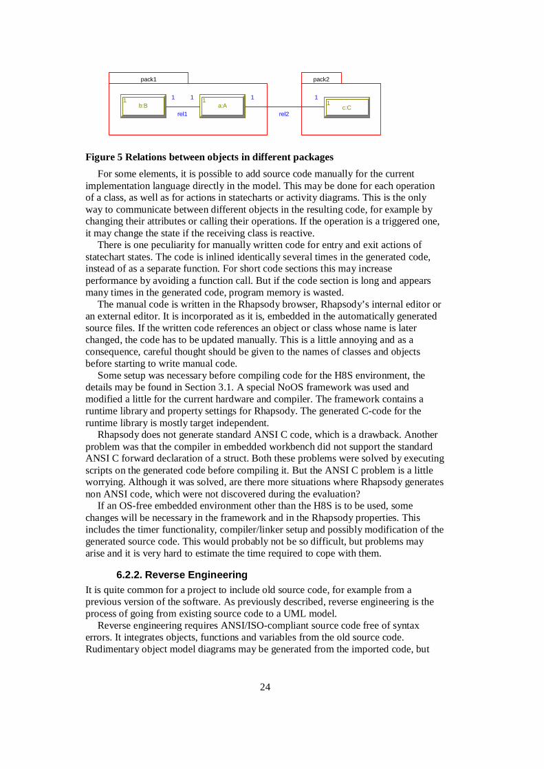
One drawback with the code generation is that relations between objects in different packages are not initiated. In Figure 5, only rel1 between the objects a and b would be initiated and not rel2 between objects a and c. This limits the possibilities to split a large design into packages. It is possible to solve the problem by writing a few lines of manual initialization code, but this is really something the tool should be expected to do.
24
pack1
a:A1
b:B1
pack2
c:C1
rel1
1 11 1
rel2
Figure 5 Relations between objects in different packages
For some elements, it is possible to add source code manually for the current implementation language directly in the model. This may be done for each operation of a class, as well as for actions in statecharts or activity diagrams. This is the only way to communicate between different objects in the resulting code, for example by changing their attributes or calling their operations. If the operation is a triggered one, it may change the state if the receiving class is reactive.
There is one peculiarity for manually written code for entry and exit actions of statechart states. The code is inlined identically several times in the generated code, instead of as a separate function. For short code sections this may increase performance by avoiding a function call. But if the code section is long and appears many times in the generated code, program memory is wasted.
The manual code is written in the Rhapsody browser, Rhapsody’s internal editor or an external editor. It is incorporated as it is, embedded in the automatically generated source files. If the written code references an object or class whose name is later changed, the code has to be updated manually. This is a little annoying and as a consequence, careful thought should be given to the names of classes and objects before starting to write manual code.
Some setup was necessary before compiling code for the H8S environment, the details may be found in Section 3.1. A special NoOS framework was used and modified a little for the current hardware and compiler. The framework contains a runtime library and property settings for Rhapsody. The generated C-code for the runtime library is mostly target independent.
Rhapsody does not generate standard ANSI C code, which is a drawback. Another problem was that the compiler in embedded workbench did not support the standard ANSI C forward declaration of a struct. Both these problems were solved by executing scripts on the generated code before compiling it. But the ANSI C problem is a little worrying. Although it was solved, are there more situations where Rhapsody generates non ANSI code, which were not discovered during the evaluation?
If an OS-free embedded environment other than the H8S is to be used, some changes will be necessary in the framework and in the Rhapsody properties. This includes the timer functionality, compiler/linker setup and possibly modification of the generated source code. This would probably not be so difficult, but problems may arise and it is very hard to estimate the time required to cope with them.
6.2.2. Reverse Engineering It is quite common for a project to include old source code, for example from a previous version of the software. As previously described, reverse engineering is the process of going from existing source code to a UML model.
Reverse engineering requires ANSI/ISO-compliant source code free of syntax errors. It integrates objects, functions and variables from the old source code. Rudimentary object model diagrams may be generated from the imported code, but

25
some manual modifications of the layout will be necessary. The imported elements may be used in the same way as if they were originally created in Rhapsody, for example when drawing new diagrams or extending old ones.
Reverse engineering was done to the header files of the driver code, in order to modify them to be used by the windows system interface. All ANSI functions were found, and also the comments describing them. Interrupt functions declared as interrupt void func(void) were not found, since that syntax is compiler specific. Structs and their attributes were found and were mapped to classes in the model. Global variables and typedefs were also imported correctly into Rhapsody.
Another test was to let Rhapsody reverse engineer the code it had generated itself. A very easy model was built, containing only one class, one object, one function and one event receptor. The code was generated and compiled successfully. It was then reverse engineered, which resulted in several errors. The resulting code was not possible to compile. Functions belonging to a class were separated from the class and displayed separately in the browser. All initialization and cleanup functions were visible in the browser. Statecharts or events were not found, but incorporated as ordinary functions and variables. The same was tried on one of the project samples supplied with Rhapsody, with the same result.
On the other hand, the purpose of reverse engineering is to incorporate hand-written source code. If a part of another model needs to be imported, there is a special menu-command for that. But it should be observed that reverse engineering is probably not a good way to transfer UML models between different development tools.
There is also a little shortcut available if external source code is to be incorporated into the project, which does not make use of reverse engineering. Filenames may be added to a component and the properties may then be set so that these files are compiled together with the rest of the configuration. A little annoying is that for each file, the filename has to be typed on the keyboard. It is not possible to choose it by browsing the file system. After adding a file, choose ”edit file” to see that path and file names are written correctly. Adding files to a component is a practical and fast way of compiling old source code together with code generated by Rhapsody, if there is no need to incorporate the old code into the model. It requires that the old source files are available when compiling.
The conclusion is that reverse engineering functions well for ordinary hand-written source code. Some manual corrections may be necessary, but the overall structure is imported. Object model diagrams may be generated automatically to reflect the classes of the old code, but the layout must be manually corrected. Reverse engineering should not be applied to code generated by Rhapsody; if some elements of another Rhapsody model is needed they may be imported by using the “Add to Model” feature.
6.2.3. Roundtrip Engineering As described in Section 1.2, roundtrip engineering enables the developer to work either with the model or with the code generated from it. The advantage would be for example that the developer could use an editor to which he is accustomed, do several changes in the generated code and then synchronize the model with the code. Rhapsody uses so called Dynamic Model Code Associativity. This synchronizes as soon as the window focus is shifted from Rhapsody to editor or vice versa.
It is most likely best to change structural information such as attribute and operation names of classes directly in Rhapsody. An editor is probably most useful for changing the code belonging to actions, functions or operations. This may also be

26
done directly in the model, as described in Section 6.2.1. Because of this, roundtrip engineering was not used much during the work on the case studies. This was a little due to personal taste, other developers may find roundtrip engineering more useful.
6.2.4. Memory Usage Case study A (the game) used 22 KB of Flash memory (8 % of the available 256 KB) and 1.5 KB of RAM (10 % of the available 16 KB). 14 KB of flash memory and 0.5 KB of RAM were used by the driver code and the noOS framework and this overhead will always be present for each UML-generated application. More about this particular measure of memory usage may be found in Section 4.4.
To test how much RAM each statechart occupies, an array of objects containing statecharts were created. By varying the number of elements in the array, it was found that each statechart or activity diagram needed only about 20 bytes of RAM with the NoOS framework, which is of course very positive.
But even though the game case study is rather small, it requires its fair share of both flash-memory and RAM. It is probable that the memory usage may be lessened more, by setting priorities in the compiler or optimizing the code. But memory is still a potential problem as the application size grows.
6.3. Evaluation of Program Testing
6.3.1. Testing in Development Environment Testing in the development environment is helped a lot with instrumentation, even though animation has some annoying flaws. A binary file with animation is about twice the size compared to one without. This is hardly interesting in a PC environment, but gives a hint as to how much memory animation would require in the target environment.
Animated statecharts may suffer from that the active state is one transition behind that of the executing program, when using the Go Step button. If the statechart is closed and opened again, the active state is moved to the right position. Triggered operations caused strange effects in the animation if called from an external program (such as a GUI), so events should be used instead.
The problems of animated statecharts are minute if compared to animated sequence diagrams. The starting point of timeouts are not shown correctly, instead the start is indicated directly above the stop point. Sometimes it looks as if messages come from outside the system boundary when they are actually generated by an object present on the diagram. Sometimes messages which are passed between objects are not displayed on the diagram. All these problems are described more closely in Section 4.4.
Another sequence diagram problem is an object contained within another class. It is not possible to refer to the object of the contained class; thus it may not be put on the sequence diagram. For example, class1 contains the object obj2 of class class2. obj1 is an instance of class1. The following ways were tried in vain to reference obj2 in obj1: obj1.obj2:Class2, obj1.obj2, obj1:Class1.obj2:Class2 and finally package.obj1.obj2. In the browser during animation, the object is reasonably referred to as obj1.obj2 and it was dragged and dropped into the sequence diagram and got the name obj1.obj2:Class2. But if the window was closed and opened again, it was miraculously changed to obj2:Class2 and did not work.

27
The last sequence diagram problem is that when a call is made from an object to a function which resides directly in a package separate from any class, the arguments to the function are lost from the diagram and only their types are shown.
Instead of animation, tracing may be used. Here the debugging is controlled from a command line prompt and all information is given in plain text. This might be useful to document the testing phase, since the output could be saved as a text file.
Summarized, animated sequence diagrams are not to be trusted and it is probably best to avoid them entirely. Animated statecharts are very helpful though, even if they have some minor problems as well. The possibility to directly inspect the values of variables and attributes in the browser is very convenient.
6.3.2. Testing in Target Environment It was desired to run the program in the target environment with animation. But it was found during the project initiation that this would involve much effort. Several libraries would have to be written, where the present libraries for operating systems might serve as a base. At least the omComAppl.lib and aomanim.lib libraries would be needed. This was considered as too much effort and not really central to the evaluation. Instrumentation is available in the development environment, but other methods must be used to debug the target environment.
6.4. Evaluation of Documentation The tool provides abilities to automatically generate documentation from the model. The program Rhapsody Reporter (which is shipped with Rhapsody) may generate text documents or HTLM files, which is described in Sections 6.4.1 and 6.4.2 respectively. Rhapsody Reporter Pro is an extended version, which enables customization of the generated reports (see Section 6.4.3). Rhapsody also has a simpler possibility of generating a document, by choosing tools-> report on model (see Section 6.4.4).
6.4.1. Rhapsody Reporter with Text Documents Paper is the classic way of documenting things, with the advantages known since Gutenberg once started with his printing presses in the 15 century. Rhapsody reporter generates documentation in RTF, MS Word or FrameMaker format, suitable for printing. There are quite a few predefined report templates (Derived Component Specifications, or dcs files for short). They define which parts of the model are to be included in the documentation and how the information is structured. A table of contents and numbered sections are handled automatically. For MS Word it is also possible to customize a style template to control the appearance of the title page, header and footer.
The template Object Type Report (full) generates a good overview of what the classes of the project contain. Unfortunately, objects of implicit type are not included here. The MS Word “feature” of displaying attributes and operations starting with a small letter as starting with a capital letter is a little annoying, especially since C is a case-sensitive language. It is positive that statecharts and activity diagrams are included as well as attributes and operations in well-structured tables.
Doing a Project Report (C) generates practically all information about the project (except for properties), but the layout of the report is not particularly good. It is very long, because each little attribute is described on several rows and there is also lots of empty space on the paper. The headers are nested up to four levels (Section 5.4.7.2), with no difference in fonts or formatting. In my opinion it would have been good with a table of the main characteristics of an element (as is done in the Object Type Report

28
(full)), with more detailed information such as implementation code following. With the present layout it is difficult to get a good overview of for example an object. Despite the massive amount of less well-structured information, unfortunately a few quite important things are missing completely. Statecharts of objects not belonging to a specified class (“objects of implicit type”) are not included. Objects belonging to a class (“objects of explicit type”) have no information about them whatsoever. Files in a component are totally left out as well.
It is also possible to generate an alphabetic list or table of all the textual model elements or diagrams regardless of type.
6.4.2. Rhapsody Reporter with HTML A modern way of documenting which is sometimes useful, is making an HTML document. Advantages are easy browsing by using hyperlinks, possibility to publish the documentation on an internet web page and that a web-browser is available on every modern computer platform. Disadvantage is that this format is not always suitable for printing on paper.
There are two HTML formats, DocView and ToolView. The DocView produces something similar to the javadoc utility for the Java language, although not quite as good.
The ToolView on the other hand is a nice format. It closely resembles the browser in Rhapsody, making it very convenient for someone familiar with the tool. The Project Report (C), which was found quite unsuitable for paper format, goes well in the HTML-format, it feels much like looking directly at the model in Rhapsody. It still lacks the same information as described above though.
The file RPYExtraction.avi is placed in the icons subdirectory and occupies 2.7 MB. If hard-drive space is an issue it seems as if it may be safely removed.
6.4.3. Rhapsody Reporter Pro The non-Pro version of Rhapsody Reporter is not of particularly high value, since the predefined report templates shipped with it are not that good, except for Object Type Report. With the Pro extension, it is possible to create own highly configurable templates. The making of templates takes a while to learn, though. Both because the concepts take a while to master and also that the tool used (DCS Editor) is quite a basic program.
During the work on the master’s thesis, a report template was constructed which extracts the most important elements of the project. Tables are frequently used to give a good overview. The template was applied to the case studies A and B, the resulting documents may be found in Appendix 1 and 2 respectively. The packages for the windows system interface as well as the NoOS framework of case study B were left out since they do not contribute to the understanding of the model. The Pro extension enables the making of templates which generate documentation that is ready to use professionally after just a few manual changes.
6.4.4. Report on Model Tool This generates a document in the RTF file format. The fonts look a little basic and there is no table of contents or title page. But as opposed to the non-Pro version of Rhapsody Reporter, it is possible to generate a printable document of the entire project and still get a pretty good overview of it. Maybe it is the different fonts, formats and indentations that make it easily readable. The pro version of Rhapsody Reporter is far superior though.

29
6.5. Evaluation of Compatibility
6.5.1. Rhapsody in Relation to the UML Specification It is interesting that on the first help page in Rhapsody, which describes the basics of the tool, the phrases “Unified Modeling Language” or ”UML” are not present. Instead UML is referred to in the sections concerning the particular diagrams and features. In fact, it could not even be found which version of UML that Rhapsody is based on. The Object Model Diagram in Rhapsody bears close resemblance to the class diagram in UML for describing classes and their relationships.
Many of the less frequently used features of UML are left out. It is not possible to attach constraints or stereotypes to operations or attributes. Stereotypes exist only for classes, components and dependencies. Deployment diagrams are not possible to draw at all. This is unfortunate since they represent one of UML’s nine standard diagrams types, even if the deployment diagrams are not so frequently used.
Because the C language is not object-oriented, some features are not included in Rhapsody in C, but in Rhapsody in C++. In the Object Model Diagram, the concepts of inheritance and aggregation are not supported, which are quite central to object-oriented design. Classes are called object_types and are implemented with structs. This means of course that the operations are not linked as tightly to the object_type, as they would have been to classes in an object-oriented language.
Interfaces are poorly supported. Rhapsody lacks the UML possibility to define interfaces in a class diagram and to show which classes that realize the interface with the realize arrow. Interfaces may only be handled in the component diagram in Rhapsody, where it is only for visualization and does not change the generated code. Interface functionality would have been very convenient to model the system interface, realized by either SystemInterfaceH8 or SystemInterfaceWin (see Section 3.3).
In some areas Rhapsody has more features than standard UML, most noticeably it may generate source code for the three supported languages.
6.5.2. Integration with other UML Development Tools Theoretically, even if a project has been done in Rhapsody up to a certain point, you could stop using the tool and continue the project by only modifying the generated source code. But the behavior of an object is often based on statecharts or activity diagrams, and the source code generated from them is cumbersome to change afterwards by hand.
This means that to stop using Rhapsody, there has to be an alternative UML tool available if the model is to be modified later on. The file format XML Metadata Interchange (XMI) is specified by the Object Management Group (OMG) and enables UML models to be stored in a tool-independent format. Unfortunately, it is not specified how diagrams are saved, so that information is lost. This may sound very bad to a graphical language like UML, but the structure and relations of classes, objects, actors and use cases are possible to transfer, which saves quite a lot of rebuilding-work. Class and use case diagrams should be fairly easy to recreate. The worst drawback is probably that statecharts and activity diagrams are lost.
Rhapsody has an XMI toolkit, which enables import and export of models in the XMI-format. An XMI file was created from one of the case studies and was then successfully reimported into Rhapsody. There was no other UML tool available to test with, which of course would have been interesting. For the tool Rational Rose, there is

30
support in the C++ version of Rhapsody for importing certain diagrams, but this feature is not available in the C version.
All this means that once Rhapsody is chosen for a particular project, it is unfortunately quite a big effort to transfer the model to another UML tool.
6.5.3. Integration with non-UML Development Tools The integration with command line tools as compiler and linker is very good. This was used to make the Embedded Workbench compiler and linker start from within Rhapsody, as described in Section 3.1.2. A batch file runs when choosing build, which is very convenient. This makes it possible to call external programs, as was done when removing the structs.
The contents of the makefile is an important way to affect an external compiler and linker. This is controlled by the Rhapsody properties and is highly configurable. Internal keywords are set to reflect settings in the Rhapsody browser and these may then be referred to in the properties. This is used for the compiler and linker switches. What is written in the switches text box in the tool is saved as a keyword and by referring to this keyword in the makefile, switches may be accessed and put in the right places.
Rhapsody is integrated with configuration management tools supporting the SCC standard, such as ClearCase, Source Integrity or Microsoft Visual SourceSafe. The latter of these tools was used in the project. The most important operations may be done from within Rhapsody, such as adding, checking in, checking out and showing history of files. Configuration management is activated by setting the project property ConfigurationManagement-> General-> UseSCCtool to yes.
Only the files in the _rpy subdirectory (corresponding to the units in the model) are saved in the CM tool and not the rpy-file itself. But the rpy-file is necessary for the project, since it keeps track of which units are included in the project. Because of this, it would be good to include the rpy-file in the CM tool as well. But if some units (files) of the model are checked out and not the rpy-file, it is not possible to save the project. This makes it difficult for several people to work on the same project using a CM tool, if new units are to be added along the way. It is necessary that the rpy-file reflects the project at each time, otherwise the entire project may become corrupt and unreadable. If there was an error message during the CM-operations, it is not always shown. Before these problems are solved in a new version of Rhapsody, it is probably safest and best to manage the files directly from the CM tool in question, or having one project for each developer. In version 4.0.1 of Rhapsody the CM abilities are said to be better, although this could not be verified since version 3.0.1 was used.
Rhapsody API is a COM interface, which lets another program read and manipulate the model. This may be done using for example Visual Basic, but was not tested in the master’s thesis. But the API may not be used for interacting with the generated programs at runtime, so it could not be used by for example the hardware-simulating GUI described before. In Rhapsody there is also an interface to the requirement specifications tool DOORS and to Visual Basic.

31
7. Conclusions One of the advantages of UML-diagrams is to communicate ideas in a standardized way. With use case and sequence diagrams, this is most likely helpful for the supplier in the dialogue with the customer who ordered the system. The other UML diagrams provide a good way of discussing design between developers in the team and also provide a good help to the individual developer to structure his work. The notation is not only standardized, it is also graphical; this makes use of the human brain’s excellent abilities to interpret and remember visual information.
The object oriented paradigm, on which UML relies, makes it possible to divide the functionality of a complex system into objects. This gives a better structure with fewer dependencies between different components and better possibilities of reuse in future projects. Objects may be assigned to different developers, once the interfaces of the individual objects have been defined.
What was said above about UML also generally applies to Rhapsody. The tool has left out quite a lot of the standard UML though, most noticeably deployment diagrams, inheritance, aggregation, composition and interfaces.
Despite this, Rhapsody is useful in all phases of the development. The core of the analysis phase is the use case diagrams. These may seem a little too simple, but they do provide an intuitive basic overview of what the system is supposed to do, which should also be understandable to people without technical skills. In the design phases, the other UML diagrams are a powerful way to structure the system. For analysis and design, conventional C-coding provides no help at all.
Implementation is much simplified, since it relies much on the model that was built in the design phase. This is especially true for the structural part, which is generated automatically from the design. The structure includes classes and their mutual dependencies. Well functioning code for behavior is generated from statecharts and activity diagrams. It is also possible to write code in the implementation language directly in the tool for states, transitions, functions and object operations. A major concern for the implementation is that Rhapsody does not generate ANSI C code. Modifications to the code may be necessary to compile with other compilers than the supported ones.
The test phase is simplified by animation using animated statecharts and the possibility to read variables directly from the tool, though it would be even more powerful if it could be done in the target environment. Animated sequence diagrams work too unpredictably to be trusted. A GUI is helpful to inject events into the model and to display output when running in the development environment.
Rhapsody has the ability of automatically generating project documentation. If the PRO extension of Rhapsody Reporter is used, the report template may be customized to generate the document in the desired way. If the model is well structured and well commented, this report requires very few changes before it may be used professionally. But without paying extra for the PRO extension, the documentation generator is almost unusable. The original version does not allow customization of the report templates, and the templates supplied with the tool are far too basic.
Some effort is required to adjust Rhapsody to an embedded target without operating system. A framework is needed, which does not rely on an operating system. Timer interrupts must be used on the hardware to make the statechart timeouts work. A way has to be found to automatically modify the generated code, since Rhapsody does not deliver ANSI C code. These issues were solved in the project and need only to be done once for each particular target environment. But the non ANSI C code is still a

32
problem, since there could be other situations when the generated code is also not standard ANSI, which were not detected in the evaluation. Another potential problem for a small embedded system is memory usage of the generated code, which is rather extensive. The possibilities for integrating command-line compilers and linkers with the tool are very good. The NoOS-framework which was used does not support events (or concurrency obviously), otherwise it provides most other functionality and works well.
Real-time is not yet standardized in UML and is also not the focus of Rhapsody. It is possible to enter timing properties for some model elements, though. These may be used for schedulability analysis by external programs, of which there is one today. There are stereotypes with icons defined for many important real-time features such as Mutex, Resource and Timer.
Summarized, Rhapsody in particular eases the design, implementation and test phases. It is also a great help for documenting with the PRO extension. There are a couple of flaws which will hopefully be corrected in future versions though. Since the tool supports the development in each development phase, it is highly probable that it saves time for the entire project. This is especially true if the project is of high complexity or involves several developers.
This thesis could be followed up by future work, for example: • An evaluation of other UML tools. Possibly a comparison of two or more. • A detailed study of Rhapsody’s real-time abilities. Scheduling analysis of code
from a UML model, using for example RAPID RMA from Tri-Pacific Software. • Analysis of the new UML Profile for Schedulability, Performance and Time. • Development of a Rhapsody library for design level debugging on an OS-free
micro-controller.
8. Acknowledgement First, I would like to thank Styrex AB for making this master’s thesis possible. This goes in particular to my supervisor Anders Bengtsson, who patiently helped me with relevant advice, skilled Lauterbach debugging and a good sense of humor.
My thanks go also to my examiner Paul Pettersson for his guidance and interest in the thesis and to Dag Erlandsson at Nohau for his clarifications concerning my numerous questions about Rhapsody.

33
9. References
[1] D. F. D’Souza, A.C. Willis: Objects, Components and Frameworks with UML. The Catalysis Approach. Addison-Wesley, 1998.
[2] OMG: Unified Modeling Language Specification, Version 1.4. OMG Document formal/01-09-67.
[3] G. Engels, R. Heckel, S. Sauer: UML - A Universal Medeling Language? ICATPN 2000, LNCS 1825, pp. 24-38, 2000
[4] I-Logix. http://www.ilogix.com. I-Logix Inc; Three Riverside Drive; Andover, Massachusetts 01810 US
[5] E. Gery, D. Harel, E. Palachi: Rhapsody: A Complete Life-Cycle Model-Based Development System. M. Butler, L. Petre, K. Sere (Eds.) IFM 2002, LNCS 2335, pp. 1-10, 2002.
[6] C. Becker, S. Glomb, M. Graf: UML Notation and Ilogix Rhapsody Tool. wwwagse.informatik.uni-kl.de/Personalia/avk/Tamagotchi98.99/UML.html
[7] G.R. de Boer: Development of a Cruise Control in UML using Rhapsody. M.Sc. Report 002R2001, Control Laboratory, University of Twente, March 2001
[8] G. Booch: Object-Oriented Analysis and Design with Applications. Benjamin/Cummins, 1994
[9] Y. Rumbaugh, M. Blaha, F. Eddy, W. Premerlani, W. Lorensen: Object-Oriented Modelling and Design. Prentice Hall, 1991.
[10] I. Jacobson et al.: Object-Oriented Software Engineering. Addison-Wesley, 1992
[11] D. Ahr: Einführung in UML. Seminar series at Ruprecht-Karls Universität, Heidelberg, summer semester 2000.
[12] P. Chen: The Entity Relationship Model- Toward a Unified View of Data. ACM Transactions on Database Systems, pp. 9-36, 1976.
[13] D. Harel: Statecharts: A Visual Formalism For Complex Systems. Science of Computer Programming, vol. 8, North-Holland, pp. 231-274, July 1987.
[14] ITU-TS Recommendation Z.120: Message Sequence Charts (MSC). ITU-TS, Geneva, 1996.
[15] B. Selic, G. Gullekson, P. Ward: Real-time Object-Oriented Modeling. Wiley, New York, 1994.
[16] B. Selic, J. Rumbaugh: Using UML for Modeling Complex Real-time Systems. ObjecTime, March 1998.
[17] OMG: UML Profile for Schedulability, Performance and Time. OMG Document ptc/02-03-02.
[18] ARTiSAN. http://www.artisansw.com. ARTiSAN Software Tools, Ltd; Stamford House; Regent Street; Cheltenham; Gloucestershire; GL50 1HN UK
[19] Rational. http://www.rational.com. Rational Software Corporation; 18880 Homestead Rd.; Cupertino, CA 95014 US
[20] B. Kernighan, D. Ritchie: The C Programming Language. Prentice Hall, Second edition, pp. 210-222, 1988

34
_____________________________________________________________________
Appendix A: Documentation of Case Study A
Project: Game
Game.rpy
Author: Magnus Lundqvist
jun 14, 2002

35
Table of Contents
1. Use Case Diagram: useCase................................................................................. 36
2. Object Model Diagram: GameDiagram................................................................ 36
3. Sequence Diagram: playGame ............................................................................. 37
4. Component Diagram: allComponents .................................................................. 38
5. Component Diagram: SI_h8s_Lib........................................................................ 39
6. Component: appLib.............................................................................................. 40
7. Component: h8s ................................................................................................... 40
8. Component: h8sBin.............................................................................................. 41
9. Component: SI_h8s_Lib....................................................................................... 41
10. Component: SI_win_Lib ...................................................................................... 41
11. Component: winBin ............................................................................................. 41
12. Package: Application............................................................................................ 41
12.1 Object Type: Customer.......................................................................................... 42 12.1.1 StateChart: Customer........................................................................................................42
12.2 Object Type: Door ................................................................................................. 42
12.3 Object Type: Game................................................................................................ 43 12.3.1 StateChart: Game .............................................................................................................43
12.4 Object Type: Robber ............................................................................................. 44 12.4.1 StateChart: Robber ...........................................................................................................44
13. Package: application ............................................................................................ 45
14. Package: Nonsense............................................................................................... 45
15. Package: NoOSOXF ............................................................................................ 45
15.1 Object Model Diagram: Reactive .......................................................................... 45
15.2 Object Model Diagram: TimerManager ............................................................... 45
15.3 Object Type: RiCEvent.......................................................................................... 46
15.4 Object Type: RiCReactive ..................................................................................... 46
15.5 Package: Containers .............................................................................................. 47 15.5.1 Object Type: RiCStaticHeap.............................................................................................47
15.6 Package: Timer ...................................................................................................... 48 15.6.1 Object Type: RiCTimeout.................................................................................................48 15.6.2 Object Type: RiCTimerManager.......................................................................................49

36
1. Use Case Diagram: useCase
The Game
playGame
player
Figure 1. Use Case Diagram: useCase
Use case of the game
Table I Actors
Actor Description
player The player of the game. Interacts with the game via keyboard and display.
Table II Use cases of Application
Use Case Description
playGame How the game is played. Customers or robbers periodically enter through the doors of a bank. The player's job is to shoot the robbers directly after they have drawn their guns. If he waits too long, the robbers shoots first and a life is lost. The player also loses a life if a robber is shot too early or if a customer is shot.
2. Object Model Diagram: GameDiagram

37
Game
itsDoor:Door3
itsRobber:Robber1
itsCustomer:Customer1
Figure 2. Object Model Diagram: GameDiagram
A game object owns three doors, which in turn own a customer and a robber each.
3. Sequence Diagram: playGame
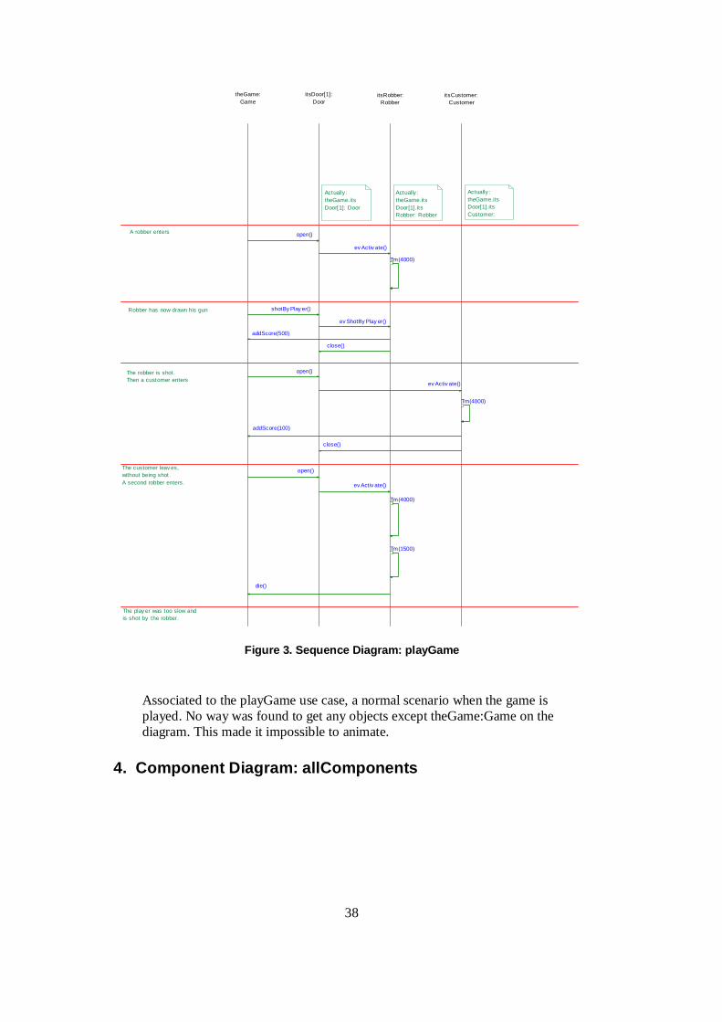
38
itsCustomer:Customer
itsDoor[1]:Door
itsRobber:Robber
theGame:Game
Robber has now drawn his gun
The robber is shot. Then a customer enters
The customer leav es, without being shot.A second robber enters.
A robber enters
The play er was too slow and is shot by the robber.
shotBy Play er()
addScore(100)
open()
Tm(4000)
Tm(1500)
addScore(500)
close()
die()
ev ShotBy Play er()
ev Activ ate()
Tm(4000)
Tm(4000)
ev Activ ate()
close()
ev Activ ate()
open()
open()
Actually : theGame.itsDoor[1]. itsRobber: Robber
Actually : theGame.itsDoor[1].itsCustomer:
Actually : theGame.itsDoor[1]: Door
Figure 3. Sequence Diagram: playGame
Associated to the playGame use case, a normal scenario when the game is played. No way was found to get any objects except theGame:Game on the diagram. This made it impossible to animate.
4. Component Diagram: allComponents

39
h8sBin
<<Executable>>
winBin
<<Executable>>
SIappLib
<<Library>>
SI_win_Lib
<<Library>>
SI_h8s_Lib
<<Library>>
Figure 4. Component Diagram: allComponents
Dependencies of the components. SI is the system interface. In the h8s environment it is realized by SI_h8s_Lib, which compiles the NoOS framework and the external driver code for the hardware. For windows, the interface is realized by SI_win_Lib, where some functions interact with a GUI. Applib is the model of the actual game application.
5. Component Diagram: SI_h8s_Lib
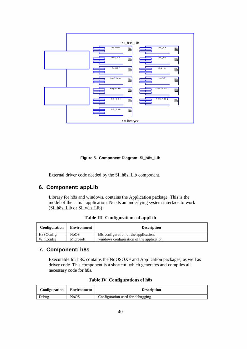
40
SI_h8s_Lib
<<Library>>
m a _ d a
d isp la y m a _ in t
sm a llH e a p
h e lp e r
w a tc h d o g
h w T im e r
k e yb o a rd
o n O ff
b u zz e r
m a _ c p u
m a _ io
m a _ c m t
Figure 5. Component Diagram: SI_h8s_Lib
External driver code needed by the SI_h8s_Lib component.
6. Component: appLib
Library for h8s and windows, contains the Application package. This is the model of the actual application. Needs an underlying system interface to work (SI_h8s_Lib or SI_win_Lib).
Table III Configurations of appLib
Configuration Environment Description
H8SConfig NoOS h8s configuration of the application. WinConfig Microsoft windows configuration of the application.
7. Component: h8s
Executable for h8s, contains the NoOSOXF and Application packages, as well as driver code. This component is a shortcut, which generates and compiles all necessary code for h8s.
Table IV Configurations of h8s
Configuration Environment Description
Debug NoOS Configuration used for debugging

41
Release NoOS Configuration used for a binary without debugging features.
8. Component: h8sBin
Executable for h8s. Needs the application library (applib) and system interface library (SI_h8s_Lib). Links the two libraries to an executable.
Table V Configurations of h8sBin
Configuration Environment Description
DefaultConfig NoOS
9. Component: SI_h8s_Lib
Library for h8s, contains the NoOSOXF package and driver code. This is the system interface for h8s.
Table VI Configurations of SI_h8s_Lib
Configuration Environment Description
DefaultConfig NoOS
10. Component: SI_win_Lib
Library. System interface for windows, with reverse engineered function prototypes from the driver code. The functions for display and keyboard interact with a GUI to simulate the hardware. The other functions are simply empty.
Table VII Configurations of SI_win_Lib
Configuration Environment Description
DefaultConfig Microsoft
11. Component: winBin
Binary for Windows. Needs the application (applib) and system interface (SI_win_Lib). Contains the GUI that simulates the hardware display and keyboard.
Table VIII Configurations of winBin
Configuration Environment Description
DefaultConfig Microsoft
12. Package: Application
The model of the game application itself. Package used for windows as well as h8s environment.
Table IX Objects of TopLevel
Object Description

42
theGame Object of type Game
12.1. Object Type: Customer
A customer who has entered the bank. Makes his errand and then leaves. The player loses a life if the customer is shot.
StateChart: Customer
active
customerShot
begin
looseLife>
closeDoor>addScore>
inactive
evShotByPlayer
tm(4000)
evActivateevDisactivate
Figure 6. StateChart: Customer
Table X Operations of Customer
Operation Return type Description
evActivate void The customer enters through its door. evDisactivate void Called to make the customer leave when the player dies. evShotByPlayer void The customer is shot by the player.
12.2. Object Type: Door
A door to the bank. Through the door a customer or a robber may enter.
Table XI Attributes of Door
Attribute Type Description
IsMarked RiCBoolean TRUE if a [ ] marker is shown around the door. This is used to indicate that this door caused the loss of a life.
IsOpen RiCBoolean TRUE if the door is open and a customer or a robber has entered. ItsPersonType int Has a robber or a customer entered? Valid when isOpen is TRUE.

43
Table XII Operations of Door
Operation Return type Description
Close void Closes the door Open void Called by itsGame when the door is opened and a visitor enters. ShotByPlayer void The player shoots at the door
12.3. Object Type: Game
The main class of the game. An instance of this class owns objects according to GameDiagram. When in the state playGame, the game is actually running.
StateChart: Game
playGame
checkKey>
generateVisitor>
processKeypress>
lifeLost>
keyWait
wait
checkKey>
initial ize>
initGame>
C
C
C
C
T
C
[me->res==TRUE]
[else]
tm(50)
[else]
tm(50)
[me->res==TRUE]
[else]
tm(4000)
[else]/dspCenter("Press F1","to continue");
[me->keyInput=='f']
[else]
[me-> l ives == 0]/dspCenter("Game","over");
tm(1500)/dspCenter("Press F1","to start");
[me-> isAlive==FALSE]
Figure 7. StateChart: Game
Table XIII Attributes of Game
Attribute Type Description
bufferBottom char %s[20]; Buffer for the display. bufferTop char %s[20]; Buffer for the display. isAlive RiCBoolean TRUE if the player is still alive. Set to false by the Robber or
Customer statechart. keyInput char Buffer for keyboard input.

44
lives int Number of lives left. Initialized to 3 at the beginning of the game. res RiCBoolean Temporary variable to indicate if a key has been pressed. score int The current score of the game.
Table XIV Operations of Game
Operation Return type Description
addScore void Adds to the score. Called from the Customer or Robber statechart. die void Called by robber or customer when player has made a mistake. resetDoors void All doors are cleared by sending evDisactivate to present customers
and thieves. Used at the beginning of the game or after the loss of a life.
updateDisplay void Prints the doors and its customers or thieves, the score and number of lives remaining.
12.4. Object Type: Robber
A robber who has entered the bank. The player should wait until the robber has drawn his gun and then shoot him. If the robber is shot before that, the player loses a life. If the player waits too long after the robber has drawn his gun, the player is shot and loses a life.
StateChart: Robber
isUnactive
isActive
closeDoor>
thiefShot>
looseLife>
drawGun>
playerShot>
shotTooEarly
begin
tm(4000)
evShotByPlayer evShotByPlayer
tm(1500)
evDisactivateevActivate
Figure 8. StateChart: Robber

45
Table XV Operations of Robber
Operation Return type Description
evActivate void The robber enters through its door. evDisactivate void Called to make the robber leave when the player dies. evShotByPlayer void The robber is shot by the player.
13. Package: application
14. Package: Nonsense
Package for visualization, not used to generate any code.
Table XVI Objects of TopLevel
Object Description
SI Visualizes the system interface. SI_h8s_Lib or SI_win_Lib realize the interface for h8s and windows environments respectively.
15. Package: NoOSOXF
NoOS (object execution) framework. Library to support the execution of generated code. Handles initialization, timers, statecharts, activity diagrams and triggered operations. Written by Dag Erlandsson at Nohau, small modifications made to adapt it to the h8s environment.
15.1. Object Model Diagram: Reactive
RiCReactive
RiCEvent
Timer
RiCTimerManager
RiCTimeout
current_event 1
<<Usage>>
<<Usage>>
<<Usage>>
destination
1
Figure 9. Object Model Diagram: Reactive
15.2. Object Model Diagram: TimerManager

46
RiCTimerManager RiCTimeoutRiCReactive
<<Usage>> <<Usage>>
Figure 10. Object Model Diagram: TimerManager
Table XVII Functions
Function Description
RiCMainTask Magnus. Needed to solve the initialization problem. RiCOXFInit RiCOXFStart timer0ISR Timer interrupt service function. Executes each ms.
15.3. Object Type: RiCEvent
Table XVIII Attributes of RiCEvent
Attribute Type Description
lId short
Table XIX Operations of RiCEvent
Operation Return type Description
Cleanup cleanup void this call is here only because code generation produces a call to it
(instead of RiCEvent_Cleanup) when a reactive object is created that contains events
Init init void this routine is here only because code generation produces a call to
it (instead of RiCEvent_Init) when a reactive object is created that contains events
isTimeout RiCBoolean
15.4. Object Type: RiCReactive
Table XX Attributes of RiCReactive
Attribute Type Description
maxNullSteps int The maximum number of continues Null transitions omrStatus long Are we in a null configuration or termination? owner void * The actual object that owns the reactive object. vtbl struct
RiCReactive_Vtbl *
Vtable of functions to process events

47
Table XXI Operations of RiCReactive
Operation Return type Description
Cleanup cleanup void this routine is here only because code generation produces a call to
it (instead of RiCReactive_Cleanup) when a reactive object is created
consumeEvent void Init init void this routine is provided only because code generation produces a
call to it (instead of RiCReactive_Init) when a reactive object is created
inNullConfig long isBehaviorStarted
RiCBoolean
popNullConfig void pushNullConfig void runToCompletion
void Run the event to completion.
setBehaviorStarted
void
setCompleteStartBehavior
void
setshouldDelete void setShouldTerminate
void
shouldCompleteRun
long
shouldCompleteStartBehavior
long
shouldDelete RiCBoolean shouldTerminate
long
startBehavior RiCBoolean takeEvent
RiCTakeEventStatus
takeTrigger RiCTakeEventStatus
terminate void
15.5. Package: Containers
Container implementations.
Object Type: RiCStaticHeap
A generic heap.
Table XXII Attributes of RiCStaticHeap
Attribute Type Description

48
count unsigned int number of elements currently on the heap isLarger RiC_isLarger compare function size unsigned int
size of allocated memory
the_heap gen_ptr * the heap
Table XXIII Operations of RiCStaticHeap
Operation Return type Description
add RiCBoolean find int Init isEmpty RiCBoolean remove gen_ptr RiCStaticHeap_isLarger
RiCBoolean
takeDown void takeUp void top gen_ptr trim gen_ptr
15.6. Package: Timer
Timer utilities.
Object Type: RiCTimeout
The order of attributes in RiCTimeout is essential. A RiCEvent attribute must be the first member in the RiCTimeout structure. There is generated code that assumes that it is.
Table XXIV Attributes of RiCTimeout
Attribute Type Description
delayTime timeUnit dueTime timeUnit ric_event struct
RiCEvent
timeoutId short
Table XXV Operations of RiCTimeout
Operation Return type Description
Cleanup compare long Create RiCTimeout * Destroy void equals RiCBoolean freeStaticTimeout
void Used by the OSCLEAN_STATIC configuration which avoids all use of dynamic memory allocation.
getDelay timeUnit getDueTime timeUnit getStaticTimeout
struct RiCTimeout *
Used by the OSCLEAN_STATIC configuration which avoids all use of dynamic memory allocation.
getTimeoutId short

49
Init initCleanTimeouts
void
RiC_Destroy_RiCTimeout
void
RiCTimeout_isLarger
RiCBoolean Used the "Me" and "MeDecl" to get rid of arg.
setDelay void setDueTime void setRelativeDueTime
void
setTimeoutId void
Object Type: RiCTimerManager
Table XXVI Attributes of RiCTimerManager
Attribute Type Description
heap struct RiCStaticHeap
the timeout request heap
heapData gen_ptr %s[DEFAULT_MAX_TM + 1];
Statically allocate the heap area that is used by RiCTimerManager for timeouts.
m_Time timeUnit current time tick timeUnit timer resolution, updated every tick ms and counts time
Table XXVII Operations of RiCTimerManager
Operation Return type Description
action void Cleanup getElapsedTime timeUnit Init isCurrentEvent RiCBoolean post void schedTm void set void timeTickCbk void unschedTm void

50
_____________________________________________________________________
Appendix B: Documentation of Case Study B
Project: Setcad
Setcad.rpy
Author: Magnus Lundqvist
jun 14, 2002

51
Table of Contents
1. Use Case Diagram: useCase................................................................................. 52
2. Sequence Diagram: CmdRsp................................................................................ 53
3. Sequence Diagram: CmdRspError1..................................................................... 54
4. Sequence Diagram: CmdRspError2..................................................................... 54
5. Sequence Diagram: Info ...................................................................................... 55
6. Sequence Diagram: InfoCmdRsp......................................................................... 56
7. Sequence Diagram: InfoError ............................................................................. 57
8. Component Diagram: allComponents .................................................................. 58
9. Component Diagram: SI_h8s_Lib........................................................................ 59
10. Component: appLib.............................................................................................. 60
11. Component: h8s ................................................................................................... 60
12. Component: h8sBin.............................................................................................. 61
13. Component: SI_h8s_Lib....................................................................................... 61
14. Component: SI_win_Lib ...................................................................................... 61
15. Component: winBin ............................................................................................. 61
16. Package: application ............................................................................................ 61
17. Package: Nonsense............................................................................................... 61
17.1 Package: PCpackage.............................................................................................. 62
18. Package: Setcad ................................................................................................... 62
18.1 Object Model Diagram: protocolOverview........................................................... 62
18.2 Object Model Diagram: tester ............................................................................... 63
18.3 Object Type: SetcadDL.......................................................................................... 64 18.3.1 StateChart: SetcadDL .......................................................................................................64
18.4 Object Type: SetcadPacket.................................................................................... 65
18.5 Object Type: SetcadTL.......................................................................................... 66 18.5.1 StateChart: SetcadTL........................................................................................................66
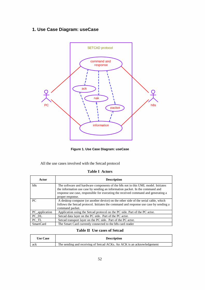
52
1. Use Case Diagram: useCase
PC
SETCAD protocol
nak
ack
command and response
information
packeth8s
Figure 1. Use Case Diagram: useCase
All the use cases involved with the Setcad protocol
Table I Actors
Actor Description
h8s The software and hardware components of the h8s not in this UML model. Initiates the information use case by sending an information packet. In the command and response use case, responsible for executing the received command and generating a proper response.
PC A desktop computer (or another device) on the other side of the serial cable, which follows the Setcad protocol. Initiates the command and response use case by sending a command packet.
PC_application Application using the Setcad protocol on the PC side. Part of the PC actor. PC_DL Setcad data layer on the PC side. Part of the PC actor. PC_TL Setcad transport layer on the PC side. Part of the PC actor. SmartCard The Smart Card currently connected to the h8s card reader
Table II Use cases of Setcad
Use Case Description
ack The sending and receiving of Setcad ACKs. An ACK is an acknowledgement

53
message sent to indicate reception of a Setcad packet. command and response
The computer sends a command packet and the h8s sends an ACK in return. After the command is processed, the h8s sends a response packet and gets an ACK from the PC. This is the normal, error-free scenario.
information The h8s sends an information packet and the PC answers with an ACK. This is the normal, error-free scenario.
nak The sending and receiving of Setcad NAKs. An NAK is a message indicating an error in a previous Setcad packet.
packet The sending and receiving of Setcad packets.
2. Sequence Diagram: CmdRsp
PC h8sSetcadTL
gotResponse(packet)
executeCommand(data, length)gotAck(counter)
gotCommand(packet)
gotACK(counter)
setResponse(data, length)
<unlimited>
counter = 12
counter = 54
counter = 54
counter = 12
Figure 2. Sequence Diagram: CmdRsp
Associated to command and response use case, normal operation scenario.

54
3. Sequence Diagram: CmdRspError1
PC h8sSetcadTL
gotCommand(packet)
gotCommand(packet)
Tm(50)
Tm(50)
Tm(50)
gotCommand(packet)
counter = 12
counter = 12
counter = 12
protocol error
Figure 3. Sequence Diagram: CmdRspError1
Associated to command and response use case, error scenario. The commands from the PC do not reach the h8s intact. The PC tries in vain to send three times according to the protocol and after that there is a protocol error.
4. Sequence Diagram: CmdRspError2
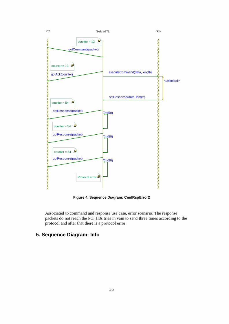
55
SetcadTL h8sPC
Tm(50)
Tm(50)
gotCommand(packet)
<unlimited>
Tm(50)gotResponse(packet)
gotResponse(packet)
setResponse(data, length)
gotResponse(packet)
gotAck(counter)executeCommand(data, length)
counter = 54
counter = 54
Protocol error
counter = 54
counter = 12
counter = 12
Figure 4. Sequence Diagram: CmdRspError2
Associated to command and response use case, error scenario. The response packets do not reach the PC. H8s tries in vain to send three times according to the protocol and after that there is a protocol error.
5. Sequence Diagram: Info

56
h8sPC SetcadTL
gotInfo(packet)
gotACK(counter)
sendInfo(data, length)
counter = 54
counter = 54
Figure 5. Sequence Diagram: Info
Associated to information use case, normal operation scenario.
6. Sequence Diagram: InfoCmdRsp

57
PC SetcadTL h8s
<unlimited>
gotACK(counter)
gotResponse(packet)
sendInfo(data, length)
gotACK(counter)
gotAck(counter)executeCommand(data, length)
gotInfo(packet)
setResponse(data, length)
gotCommand(packet)
counter = 54
counter = 55
counter = 12
counter = 12
counter = 55
counter = 54
Figure 6. Sequence Diagram: InfoCmdRsp
Associated to information use case and command and response use case, normal operation scenario. The two use cases may be interleaved.
7. Sequence Diagram: InfoError

58
SetcadTLPC h8s
sendInfo(data, length)
Tm(50)
Tm(50)
Tm(50)
gotInfo(packet)
gotInfo(packet)
gotInfo(packet)
protocol error
counter = 54
counter = 54
counter = 54
Figure 7. Sequence Diagram: InfoError
Associated to information use case, error scenario. The information packets form h8s do not reach the PC intact. H8s tries in vain to send three times according to the protocol and after that there is a protocol error.
8. Component Diagram: allComponents

59
SI
SI_win_Lib
<<Library>>
appLib
<<Library>>
SI_h8s_Lib
<<Library>>
h8sBin
<<Executable>>
winBin
<<Executable>>
Figure 8. Component Diagram: allComponents
Dependencies of the components. SI is the system interface. In the h8s environment it is realized by SI_h8s_Lib, which compiles the NoOS framework and the external driver code for the hardware. For windows, the interface is realized by SI_win_Lib, where some functions interact with a GUI. Applib is the actual Setcad model.
9. Component Diagram: SI_h8s_Lib

60
SI_h8s_Lib
<<Library>>
w a tc h d o g
m a _ d a
m a _ io
m a _ c p u
m a _ c m t
b u zz e r
t im e r
m a _ in t
o n O ff
k e yb o a rd sm a llH e a p
d isp la y
Figure 9. Component Diagram: SI_h8s_Lib
External driver code needed by the SI_h8s_Lib component.
10. Component: appLib
Library for h8s and windows, contains the Setcad package. This is the model of the actual setcad protocol. Needs an underlying system interface to work (SI_h8s_Lib or SI_win_Lib).
Table III Configurations of appLib
Configuration Environment Description
H8SConfig NoOS h8s configuration of the application. WinConfig Microsoft windows configuration of the application.
11. Component: h8s
Executable for h8s, contains the NoOSOXF and Setcad packages, as well as driver code. This component is a shortcut, which generates and compiles all necessary code for h8s.
Table IV Configurations of h8s
Configuration Environment Description
Debug NoOS Configuration used for debugging with Lauterbach.

61
Release NoOS Configuration used for a binary without debugging features.
12. Component: h8sBin
Executable for h8s. Needs the application library (applib) and system interface library (SI_h8s_Lib). Links the two libraries to an executable.
Table V Configurations of h8sBin
Configuration Environment Description
DefaultConfig NoOS
13. Component: SI_h8s_Lib
Library for h8s, contains the NoOSOXF package and driver code. This is the system interface for h8s.
Table VI Configurations of SI_h8s_Lib
Configuration Environment Description
DefaultConfig NoOS
14. Component: SI_win_Lib
Library. System interface for windows, with reverse engineered function prototypes from the driver code. The functions for display and keyboard interact with a GUI to simulate the hardware. The other functions are simply empty.
Table VII Configurations of SI_win_Lib
Configuration Environment Description
DefaultConfig Microsoft
15. Component: winBin
Binary for Windows. Needs the application (applib) and system interface (SI_win_Lib). Contains the GUI that simulates the hardware display and keyboard.
Table VIII Configurations of winBin
Configuration Environment Description
DefaultConfig Microsoft
16. Package: application
17. Package: Nonsense
Package for visualization and test, not used to generate any code.

62
Table IX Objects of TopLevel
Object Description
Cstester May be used when debugging to set up a packet and calculate its checksum. SI Visualizes the system interface. SI_h8s_Lib or SI_win_Lib realize the interface for
h8s and windows environments respectively.
Table X Attributes of CStester
Attribute Type Description
Buff unsigned char %s[10];
The data section buffer
crc1 int The first byte of the calculated checksum crc2 int The second byte of the calculated checksum Cs Unsigned long The calculated checksum
17.1. Package: PCpackage
Only used to illustrate the PC side in the object model diagrams.
18. Package: Setcad
The model of the actual application, which handles the Setcad protocol.
18.1. Object Model Diagram: protocolOverview

63
PCpack
PC_DL
PC_application
PC_TL
{Transport Layer}
DL:SetcadDL1
TL:SetcadTL1
{Application}
{Data Layer}
h8s
PC h8s
Figure 13. Object Model Diagram: protocolOverview
The layers of the protocol on the h8s and PC side.
18.2. Object Model Diagram: tester
tester1
TL:SetcadTL1
DL:SetcadDL1
1 1
Figure 14. Object Model Diagram: tester

64
Associations of Setcad tester.
Table XXII Objects of TopLevel
Object Description
DL Object of type SetcadDL. Executer Object of type SetcadExecuter. Tester Used to test the protocol in the NT environment. Generates triggered operations upon
receiving events from the Rhapsody event generator. TL Object of type SetcadTL.
Table XXIII Events of Setcad
Event Description
Crack Event to SETCADtester to simulate an ACK CRcmd Event to SETCADtester to simulate a command CRcmdOld Event to SETCADtester to simulate an old command Crinfo Event to SETCADtester to simulate an information packet Crrec Event to SETCADtester to simulate the reception of a byte CRrsp Event to SETCADtester which constructs a response packet
18.3. Object Type: SetcadDL
Data layer for the Setcad protocol, handling communication at byte level. Responsible for receiving individual bytes and for classifying an incoming message as command, ACK, NAK or garbage. Builds command packet from the received byte stream. Also enables for the layer above to send an ACK, a NAK or an entire packet.
StateChart: SetcadDL

65
checkCommand>
checkForMore
gotACK>
gotGarbage>
idle>
receiv e>
possibleMessage>
inv alidCommand>
gotCommand>
gotNAK>
GO_IDLE
C
C
C
C
C
C
GO_IDLE[me->isReceiv ing]
[me-> isCommand]
[else]
[else]
[else]
[*(me-> messageStart) == SetcadDL_ACK]
tm(10)
[else]
[else]
[else]
tm(10)
[me-> buf f erIndex< me-> buf f erEnd]
[me->isReceiv ing]
[*(me-> messageStart) == SetcadDL_PACKET]
[me->isReceiv ing]
[*(me-> messageStart) == SetcadDL_NAK]
After one message has been processed, the state machine reaches the checkForMore state. If there are sti l l bytes on the buffer or if another byte has been received while handling the first message, that is taken care of.
Figure 15. StateChart: SetcadDL
Table XXIV Attributes of SetcadDL
Attribute Type Description
BufferEnd int Index of the first free position in the receive buffer. That means also the number of bytes currently in the buffer.
BufferIndex int Position of where to read next byte in the receive buffer BufferStart unsigned char
* Points to the start of the receive buffer. Useful if several buffers are used when debugging.
IsCommand RiCBoolean Help variable set to true in the state CheckCommand if the message was a command
IsReceiving RiCBoolean Help variable set to true by the driver code when a byte is received. When this is not done in a period of 10 ms, the end of the message is found.
MessageStart unsigned char *
Points to the start of the next message to process. Calculated using bufferStart and bufferIndex
ReceiveBuffer unsigned char %s [270];
Receive buffer where the message is put when it is read from the buffer in the driver code
Table XXV Operations of SetcadDL
Operation Return type Description
SendACK void Sends an ACK to the PC with the specified packet counter value. SendNAK void Sends a NAK to the PC with the specified packet counter value. SendPacket void Sends a SETCAD packet to the PC.
18.4. Object Type: SetcadPacket
A packet of the setcad protocol

66
Table XXVIII Attributes of SetcadPacket
Attribute Type Description
C unsigned char Packet counter CRC1 unsigned char Checksum (most significant byte) CRC2 unsigned char Checksum (least significant byte) Data unsigned char
* Pointer to the data section
LEN1 unsigned char Length of packet (most significant byte) LEN2 unsigned char Length of packet (least significant byte) Length unsigned int Length of packet, as in LEN1 and LEN2. The length is the number
of bytes in the sections data, C, T, CRC1 and CRC2. S unsigned char Start character. Always 0x24 for a packet. T unsigned char Type of Setcad packet.
T=0 . Command packet T=1 . Response packet T=2 . Information packet
Table XXIX Operations of SetcadPacket
Operation Return type Description
ComputeChecksum
unsigned long Computes the checksum of the packet.
SetChecksum void Sets the checksum of the packet SetData void Sets the data and length values. The parameter length is the length
of the data section. Four is added to this number to reflect that also the C, T, CRC1 and CRC2 bytes are included in the length of the SETCAD packet.
18.5. Object Type: SetcadTL
Transport layer of the setcad protocol, handling complete Setcad packets, ACKs and NAKs. Responsible for sending and receiving ACKs, which indicate that packets were properly delivered and to resend packets if that was not the case.
StateChart: SetcadTL
communicationFailure>
running>
InformationPacket CommandAndResponse
OldCommand
running>
error
sendInfoPacket> notOK
idle
buildPacket>
waitForACK
wait>
ExecuteCommand>
idle
waitForACK
sendACK>
sendResponsePacket>
buildResponse>
error
notOK
sendAck>
idle
C C
sendInfo/SetcadPacket_setData( &(me-> packInfo), params-> data, params-> length);
/me-> nrOfTriesInfo = 0;
gotNAK[params-> counter == me-> infoCounter]
gotACK[params-> counter == me-> infoCounter]
/me-> nrOfTriesInfo ++ ;
[me-> nrOfTriesInfo < 3]
[else]
tm(70)
/me-> nrOfTriesRsp = 0;[else]
/me-> nrOfTr iesRsp ++ ;
tm(70)
gotACK[params-> counter == me-> rspCounter]
gotNAK[params-> counter == me-> rspCounter]
gotCommand[SetcadTL_counterOK (me, params-> packet) ]/me-> packCmd = params-> packet;
/dspCenter("Setcad Tester:","Go!!");
[me-> nrOfTr iesRsp < 3]
gotCommand[params-> packet-> C == me-> cmdCounter ]
reset
/me-> cmdCounter = -1;
Figure 17. StateChart: SetcadTL

67
Table XXX Attributes of SetcadTL
Attribute Type Description
CmdCounter int Sequence number of the latest Setcad command packet received InfoCounter int Sequence number of the latest Setcad information packet sent NrOfTriesInfo int Number of times the present information packet has been sent NrOfTriesRsp int Number of times the present response packet has been sent PackCmd SetcadPacket
* Pointer to the SETCAD command packet built by the data layer
PacketCounter int Sequence number of the next Setcad packet to be sent, response or information.
RspCounter int Sequence number of the latest Setcad response packet sent
Table XXXI Operations of SetcadTL
Operation Return type Description
CounterNext int Computes the following counter value. CounterOK RiCBoolean Checks if the counter of the received command packet is correct.
That is the case if it is different from the counter of the previous command.
GotACK void Called by the data layer when an ACK was received. GotCommand void Called by the data layer when a Setcad command packet was
received. GotGarbage void Called by the data layer when garbage was received. GotNAK void Called by the data layer when a NAK was received. Reset void May be called by the application to reset the protocol after a
protocol failure. SendInfo void Sends a Setcad information packet. The parameter length is the
length of the data section (!). SetResponse void Sets the data and length values of the Setcad response packet. The
parameter length is the length of the data section (!).

Related Documents