Contacts: Ian Graham or Alan Wills +44-161-225 3240; [email protected] Copyright © MMI – Trireme International Ltd. All rights reserved UML – a tutorial UML – a tutorial ..................................................................................................... 1 1 The history of object-oriented analysis and design methods ............................. 2 2 Software engineering ...................................................................................... 7 2.1 Responsibility-driven versus data-driven approaches .............................. 12 2.2 Translational versus elaborational approaches ........................................ 13 3 Object-oriented analysis and design using UML ............................................ 13 3.1 Types and classes .................................................................................... 13 3.1 Object structures ..................................................................................... 18 3.2 Using use cases to discover types ............................................................ 28 3.3 Invariants and rulesets ............................................................................ 35 3.4 Invariants and encapsulation .................................................................. 43 3.5 State models ........................................................................................... 45 3.6 Moving to component design .................................................................. 48 3.8 The design process ................................................................................. 55 3.9 Documenting models .............................................................................. 57 3.10 Real-time extensions............................................................................. 58 4 Identifying objects ......................................................................................... 60 4.2 Task analysis ........................................................................................... 65 4.3 Kelly grids............................................................................................... 68 5 CASE tools ................................................................................................... 71 6 Patterns, architecture and decoupled design .................................................. 73 6.1 Design patterns for decoupling ................................................................ 87 7 Designing components .................................................................................. 97 7.1 Components for flexibility .................................................................... 100 7.2 Large-scale connectors ......................................................................... 101 7.3 Mapping the business model to the implementation .............................. 103 8 Notation summary....................................................................................... 105 8.1 Object modelling symbols ..................................................................... 105 8.2 Action (use case) modelling symbols ........................................................ 110 8.3 Sequence and collaboration diagram symbols .......................................... 110 8.4 State modelling symbols ........................................................................... 112 8.5 Action or activity diagram symbols .......................................................... 114 8.6 Implementation and component modelling symbols ................................. 115 8.7 Collaborations and patterns ...................................................................... 116 8.8 Real-time notation: ports and connectors.................................................. 116 9 Further reading ........................................................................................... 117 10 Exercises ................................................................................................... 118 UML is the international standard notation for object-oriented analysis and design. It is defined by the Object Management Group (www.omg.org ) and is currently at

Welcome message from author
This document is posted to help you gain knowledge. Please leave a comment to let me know what you think about it! Share it to your friends and learn new things together.
Transcript

Contacts: Ian Graham or Alan Wills +44-161-225 3240; [email protected] Copyright © MMI – Trireme International Ltd. All rights reserved
UML – a tutorial UML – a tutorial.....................................................................................................1
1 The history of object-oriented analysis and design methods .............................2 2 Software engineering ......................................................................................7
2.1 Responsibility-driven versus data-driven approaches ..............................12 2.2 Translational versus elaborational approaches ........................................13
3 Object-oriented analysis and design using UML............................................13 3.1 Types and classes ....................................................................................13 3.1 Object structures.....................................................................................18 3.2 Using use cases to discover types ............................................................28 3.3 Invariants and rulesets............................................................................35 3.4 Invariants and encapsulation ..................................................................43 3.5 State models ...........................................................................................45 3.6 Moving to component design..................................................................48 3.8 The design process .................................................................................55 3.9 Documenting models..............................................................................57 3.10 Real-time extensions.............................................................................58
4 Identifying objects.........................................................................................60 4.2 Task analysis...........................................................................................65 4.3 Kelly grids...............................................................................................68
5 CASE tools ...................................................................................................71 6 Patterns, architecture and decoupled design ..................................................73
6.1 Design patterns for decoupling ................................................................87 7 Designing components ..................................................................................97
7.1 Components for flexibility....................................................................100 7.2 Large-scale connectors .........................................................................101 7.3 Mapping the business model to the implementation..............................103
8 Notation summary.......................................................................................105 8.1 Object modelling symbols.....................................................................105
8.2 Action (use case) modelling symbols ........................................................110 8.3 Sequence and collaboration diagram symbols ..........................................110 8.4 State modelling symbols...........................................................................112 8.5 Action or activity diagram symbols ..........................................................114 8.6 Implementation and component modelling symbols .................................115 8.7 Collaborations and patterns......................................................................116 8.8 Real-time notation: ports and connectors..................................................116 9 Further reading ...........................................................................................117 10 Exercises...................................................................................................118
UML is the international standard notation for object-oriented analysis and design. It is defined by the Object Management Group (www.omg.org) and is currently at

Contacts: Ian Graham or Alan Wills +44-161-225 3240; [email protected] Copyright © MMI – Trireme International Ltd. All rights reserved
release 1.4 with 2.0 expected next year. UML provides several notations which are described in detail in Ian Graham's Object-Oriented Methods (Addison-Wesley, 2001); Chapters 1, 6 and 7 give a detailed coverage of object-oriented analysis and design using UML and Catalysis. This tutorial is based on it.
UML is a sound basis for object-oriented methods including those that apply to component based development. One such method is Catalysis which is described elsewhere on this site. To buy the book click here.
This tutorial focuses both on the widely used UML notation and upon the principles of modelling. Our treatment is particularly based on Catalysis (D’Souza and Wills, 1999) and SOMA (Graham, 1995). The focus is on best practice and we suggest a set of requirements for a practical analysis and design technique.
We introduce and explain the Unified Modelling Language (UML). UML is a standardized notation for object-oriented analysis and design. However, a method is more than a notation. To be an analysis or design method it must include guidelines for using the notation and methodological principles. To be a complete software engineering method it must also include procedures for dealing with matters outside the scope of mere software development: business and requirements modelling, development process, project management, metrics, traceability techniques and reuse management. In this tutorial we focus on the notational and analysis and design aspects.
1 The history of object-oriented analysis and design methods
The development of computer science as a whole proceeded from an initial concern with programming alone, through increasing interest in design, to concern with analysis methods only latterly. Reflecting this perhaps, interest in object-orientation also began, historically, with language developments. It was only in the 1980s that object-oriented design methods emerged. Object-oriented analysis methods emerged during the 1990s.
Apart from a few fairly obscure AI applications, up until the 1980s object-orientation was largely associated with the development of graphical user interfaces (GUIs) and few other applications became widely known. Up to this period not a word had been mentioned about analysis or design for object-oriented systems. In the 1980s Grady Booch published a paper on how to design for Ada but gave it the prophetic title: Object-Oriented Design. Booch was able to extend his ideas to a genuinely object-oriented design method by 1991 in his book with the same title, revised in 1993 (Booch, 1994) [sic].
With the 1990s came both increased pressures on business and the availability of cheaper and much more powerful computers. This led to a ripening of the field and to a range of applications beyond GUIs and AI. Distributed, open computing became both possible and important and object technology was the basis of much

Contacts: Ian Graham or Alan Wills +44-161-225 3240; [email protected] Copyright © MMI – Trireme International Ltd. All rights reserved
development, especially with the appearance of n-tier client-server systems and the web, although relational databases played and continue to play an important rôle. The new applications and better hardware meant that mainstream organizations adopted object-oriented programming and now wanted proper attention paid to object-oriented design and (next) analysis. Concern shifted from design to analysis from the start of the 1990s. An object-oriented approach to requirements engineering had to wait even longer.
The first book with the title Object-Oriented Systems Analysis was produced by Shlaer and Mellor in 1988. Like Booch‘s original paper it did not present a genuinely object-oriented method, but concentrated entirely on the exposition of extended entity-relationship models, based on an essentially relational view of the problem and ignoring the behavioural aspects of objects. Shlaer and Mellor published a second volume in 1992 that argued that behaviour should be modelled using conventional state-transition diagrams and laid the basis of a genuinely OO, albeit data-driven, approach that was to remain influential through its idea of ‘translational’ modelling, which we will discuss. In the meanwhile, Peter Coad had incorporated behavioural ideas into a simple but object-oriented method (Coad and Yourdon, 1990; 1991). Coad’s method was immediately popular because of its simplicity and Booch’s because of its direct and comprehensive support for the features of C++, the most popular object-oriented programming language of the period in the commercial world. This was followed by an explosion of interest in and publication on object-oriented analysis and design. Apart from those already mentioned, among the most significant were OMT (Rumbaugh et al., 1991), Martin-Odell (1992), OOSE (Jacobson et al., 1992) and RDD (Wirfs-Brock et al., 1990). OMT was another data-driven method rooted as it was in relational database design, but it quickly became the dominant approach precisely because what most programmers were forced to do at that time was to write C++ programs that talked to relational databases.
OMT (Rumbaugh et al., 1991) copied Coad’s approach of adding operations to entity-type descriptions to make class models but used a different notation from all the previous methods. Not only was OMT thoroughly data-driven but it separated processes from data by using data flow diagrams separately from the class diagrams. However, it emphasized what Coad had only hinted at and Shlaer and Mellor were yet to publish: the use of state-transition diagrams to describe the life cycles of instances. It also made a few remarks about the micro development process and offered very useful advice on how to connect object-oriented programs with relational databases. Just as Booch had become popular with C++ programmers because of its ability to model the semantic constructs of that language precisely, so OMT became popular with developers for whom C++ and a relational database were the primary tools.
Two of OMT’s chief creators, Blaha and Premerlani (1998), confirm this with the words: ‘The OMT object model is essentially an extended Entity-Relationship approach’ (p.10). They go on to say, in their presentation of the second-generation

Contacts: Ian Graham or Alan Wills +44-161-225 3240; [email protected] Copyright © MMI – Trireme International Ltd. All rights reserved
version of OMT, that the ‘UML authors are addressing programming applications; we are addressing database applications’. Writing in the preface to the same volume, Rumbaugh even makes a virtue out of the relational character of OMT. We feel that a stricter adherence to object-oriented principles and to a responsibility-driven approach is a necessity if the full benefits of the object-oriented metaphor are to be obtained in the context of a fully object-oriented tool-set.
In parallel with the rise of the extended entity-relationship and data-driven methods, Wirfs-Brock and her colleagues were developing a set of responsibility-driven design (RDD) techniques out of experience gained more in the world of Smalltalk than that of the relational database. The most important contributions of RDD were the extension of the idea of using so-called CRC cards for design and, later, the introduction of the idea of stereotypes. CRC cards showed Classes with their Responsibilities and Collaborations with other objects as a starting point for design. These could then be shuffled and responsibilities reallocated in design workshops. The idea had originated from the work of Beck and Cunningham at Tektronix, where the cards were implemented using a hypertext system. Moving to physical pieces of cardboard enhanced the technique by allowing designers to anthropomorphize their classes and even consider acting out their life cycles.
Objectory was a proprietary method that had been around much longer than most object-oriented methods. It originated in the Swedish telecommunications industry and emerged in its object-oriented guise when Jacobson et al. (1992) published part of it (OOSE) in book form. The major contribution of this method was the idea that analysis should start with use cases rather than with a class model. The classes were then to be derived from the use cases. The technique marked an important step forward in object-oriented analysis and has been widely adopted, although it is possible to make some fairly severe criticisms of it. Objectory was the first OO method to include a bona fide, although partial, development process.
OBA (Object Behaviour Analysis) originated from Smalltalk-dominated work at ParcPlace and also included a process model that was never fully published although some information was made available (Goldberg and Rubin, 1995; Rubin and Goldberg, 1992). One interesting feature of OBA was the use of stereotypical scripts in place of use cases.
Coming from the Eiffel tradition, Waldén and Nerson’s (1995) BON (Business Object Notation) emphasized seamlessness and hinted at a proto-process. However, this approach (and indeed its very seamlessness) depended on the adoption of Eiffel as a specification language throughout the process. It made important contributions to the rigour of object-oriented analysis as did Cook and Daniels’ (1994) Syntropy. BON improves rigour using the Eiffel idea of class invariants while Syntropy does this and further emphasizes state machines.
MOSES (Henderson-Sellers and Edwards, 1994) was the first OO method to include a full-blown development process, a metrics suite and an approach to reuse management. SOMA (Graham, 1995), which appeared in its mature form roughly contemporaneously with MOSES and was influenced by it, also included all these

Contacts: Ian Graham or Alan Wills +44-161-225 3240; [email protected] Copyright © MMI – Trireme International Ltd. All rights reserved
features, as well as attempting to fuse the best aspects of all the methods published to date and go beyond them; especially in the areas of requirements engineering, process, agent-based systems and rigour.
In 1994 there were over 72 methods or fragments of methods. The OO community soon realized that this situation was untenable if the technology was to be used commercially on any significant scale They also realized that most of the methods overlapped considerably. Therefore, various initiatives were launched aimed at merging and standardizing methods.
Thus far, to the eyes of the developer there appeared a veritable soup of object-oriented analysis and design methods and notations. It was an obvious development to try to introduce some kind of unification and the Fusion method (Coleman et al., 1994; Malan et al., 1996) represents one of the first attempts to combine good techniques from other published methods, although some commentators have viewed the collection of techniques as poorly integrated. There is a process associated with Fusion although published descriptions of it appear incomplete compared to the proprietary versions sold by Hewlett-Packard. The modern object-oriented developer had to find a way to pick out the noodles from this rich soup of techniques. Because of this and because there were many similarities between methods it began to be felt by most methodologists that some sort of convergence was in order
The OPEN Consortium was an informal group of about 30 methodologists, with no common commercial affiliation, that wanted to see greater method integration but felt strongly that methods should include a complete process, should be in the public domain, should not be tied to particular tools and should focus strongly on scientific integrity as well as pragmatic issues. The founding members of OPEN were Brian Henderson-Sellers and myself who began to integrate the MOSES and SOMA process models. The result was published as Graham et al. (1997b). They were soon joined by Don Firesmith who started work on an integrated notation (OML) with the aim of exhibiting a more pure object-oriented character than the OMT-influenced UML and one that would be easier to learn and remember (Firesmith et al., 1997).
Jim Rumbaugh left GE to join Grady Booch at Rational Inc. These two merged their notations into what became the first version of UML (Booch et al., 1999). Later they were joined by Ivar Jacobson who added elements of his Objectory notation and began the development of the Rational Unified Process (RUP). UML was submitted to the OMG for standardization and many other methodologists contributed ideas, although the CASE tool vendors have generally resisted both innovations that would cause them to rewrite their tools and simplifications that would make their tools less useful. The OPEN consortium proposed the semantically richer OML which was largely ignored despite many good ideas, probably largely due to its over-complicatedness (Firesmith at al., 1997). Real-time elements were added based on the ROOM method (Selic et al., 1994) and a formal constraint language, OCL, heavily influenced by Syntropy (Cook and Daniels,

Contacts: Ian Graham or Alan Wills +44-161-225 3240; [email protected] Copyright © MMI – Trireme International Ltd. All rights reserved
1994) introduced. A notation for multiple interfaces to classes was based on Microsoft’s work on COM+. Activity diagrams for process modelling were based on the Martin-Odell method. The idea of stereotypes adopted in UML was based on ideas proposed by Rebecca Wirfs-Brock (though much mangled in the first realizations of the standard). The struggle to improve UML continues and we will therefore not assume a completely fixed character for it in this text. Thus were issues of notation largely settled by the end of the 1990s, which has shifted the emphasis to innovation in the field of method and process. Among the most significant contributions to analysis and design methodology, following the naissance of UML, was Catalysis (D’Souza and Wills, 1999) which was the first method to contain specific techniques for component-based development along with coherent guidance on how the UML should be used. Our own work showed that objects could be regarded as intelligent agents if rulesets were added to type specifications. This generalized the insistence in other methods (notably BON, Syntropy and Catalysis) that invariants were needed to specify types fully.
Figure 1 shows the relationships between several object-oriented methods, languages and notations discussed in this tutorial. See Appendix B for a discussion of these methods and others.
OPENGraham et al., 1997
Process, notation
OMTRumbaugh et al., 1991
ObjectoryJacobson et al., 1992
A process for object-oriented design
Real Time OOMSelic et al., 1994
Object Management Groupco-ordinator
CatalysisD'Souza and Wills, 1999
Entity-Relational ModellingCodd et al., 1980
Multiple views of static relationships;design based on users' concepts
Formalspecification
Larch, Z &VDM c.1980
UML1997
C++
Smalltalk
CRCBeck et al.
EiffelMeyer, 1988
Database design
SyntropyCook & Daniels, 1994
FusionColeman et al., 1994
SOMAGraham, 1991
Rulesets, OO RAD,business modelling
Coad, 1990
Odell , 1991Activity diagrams
Booch, 1991Managing object designs
and interdependencies
AdaLarge system modular real-time programming
Figure 1 Some of the influences on UML.
Contacts: Ian Graham or Alan Wills +44-161-225 3240; [email protected] Copyright © MMI – Trireme International Ltd. All rights reserved
2 Software engineering
Object-oriented methods cover, at least, methods for design and methods for analysis. Sometimes there is an overlap, and it is really only an idealization to say that they are completely separate activities. Ralph Hodgson (1990) argued that the systems development process is one of comprehension, invention and realization whereby a problem domain is first grasped or apprehended as phenomena, concepts, entities, activities, rôles and assertions. This is comprehension and corresponds entirely to analysis. However, understanding the problem domain also entails simultaneously apprehending frameworks, components, computational models and other mental constructs which take account of feasible solution domains. This inventive activity corresponds to the design process. Of course, most conventional thinkers on software engineering will be horrified that we suggest that understanding the answer precedes, to some extent, understanding the problem, but that is precisely what we are saying. All other cognitive processes proceed in this way, and we see no reason why software engineering should be different. These considerations also enter into the realization process where these frameworks and architectural components are mapped onto compilers and hardware. Advocates of evolutionary development have long argued that it is beneficial not to make a rigid separation between analysis, design and implementation. On the other hand, managerial and performance considerations lead to serious questions about the advisability of prototyping in commercial environments. Graham (1991d) suggested a number of ways in which prototyping could be exploited but controlled. At the root of this debate are ontological and epistemological positions concerning what objects are and how we can apprehend them or know about them. Reusable specifications
Biggerstaff and Richter (1989) suggested that less than half of a typical system can be built of reusable software components, and that the only way to obtain more significant gains in productivity and quality is to raise the level of abstraction of the components. Analysis products or specifications are more abstract than designs. Designs are more abstract than code. Abstract artefacts have less detail and less reliance on hardware and other implementation constraints. Thus the benefits of reuse can be obtained earlier in a project, when they are likely to have the greatest impact. However, the less detailed an object is the less meaningful it becomes. Where extensibility or semantic richness is important greater detail may be required, and this may compromise reuse to some extent. This leads us to ask if object-oriented analysis and design techniques exist which can deliver the benefits of reuse and extensibility. In the face of still evolving object-oriented programming and component technology, this question attains even more significance: can we

Contacts: Ian Graham or Alan Wills +44-161-225 3240; [email protected] Copyright © MMI – Trireme International Ltd. All rights reserved
gain these benefits now, pending the appearance of more mature, more stable languages and frameworks? We think we can. However, the subsidiary question of which methods of design and analysis we should use is harder. The popular notation is UML, which was first standardized by the OMG in 1997, but UML is only a notation. We need to add techniques and guidelines to it to arrive at a method.
Software houses and consultancies ought to be particularly interested in reusable and extensible specifications. The reason for this is pecuniary. What the people employed by software houses and consultancies do, to earn their livings, is work with clients to understand their businesses and their requirements and help them produce software solutions to their problems. Having gained all this valuable experience, consultants then go on to the next client and sell what they have learnt, perhaps for a higher fee justified by the extra knowledge. Some firms go further. They try to encapsulate their experience in customizable functional specifications. For example, a firm We worked for, BIS Information Systems, had a product in the 1980s called the ‘mortgage model’, which was a functional specification of a mortgage application, based on a number of such projects and capable of being tailored to the needs of a particular client. The trouble was, for BIS at least, that the mortgage model could not be sold to greengrocers or washing machine manufacturers, even though some of the entities, such as account, may apply to all these businesses. What is required, then, is a set of reusable specification components that can be assembled into a functional specification suitable for any business. Object-oriented analysis, and to a lesser extent design, promises to deliver such a capability, even if the only extant reusable frameworks, such as IBM’s San Francisco, are still delivered as code.
To fix terminology, let us begin with a vastly oversimplified picture of the software development process or life cycle. According to this simplified model, development begins with the elicitation of requirements and domain knowledge and ends with testing and subsequent maintenance. Between these extremes occur three major activities: specification and logical modelling (analysis), architectural modelling (design) and implementation (coding and testing). Of course this model permits iteration, prototyping and other deviations, but we need not consider them at this stage. In real life, despite what the textbooks tell us, specification and design overlap considerably. This seems to be especially true for object-oriented design and analysis because the abstractions of both are modelled on the abstractions of the application, rather than the abstractions appropriate to the world of processors and disks. Design may be divided into logical and physical design, as is well known. In object-oriented design the logical stage is often indistinguishable from parts of object-oriented analysis. One of the major problems encountered with structured analysis and structured design methods is the lack of overlap or smooth transition between the two. This often leads to difficulties in tracing the products of design back to original user requirements or analysis products. The approach adopted in object-oriented analysis and design tends to merge the systems analysis with the
Contacts: Ian Graham or Alan Wills +44-161-225 3240; [email protected] Copyright © MMI – Trireme International Ltd. All rights reserved
process of logical design, although there is still a distinction between requirements elicitation and analysis and between logical and physical design. Nevertheless, object-oriented analysis, design and even programming, through working consistently with a uniform conceptual model of objects throughout the life cycle, at least promises to overcome some of the traceability problems associated with systems development. One of the chief reasons for this is the continuum of representation as the object-oriented software engineer moves from analysis through design to programming. In these transitions the unit of currency, as it were, remains the same; it is the object. Analysts, designers and programmers can all use the same representation, notation and metaphor rather than having to use DFDs at one stage, structure charts at the next and so on.
The benefits of object-oriented analysis and design specifically include:
� required changes are localized and unexpected interactions with other program modules are unlikely;
� inheritance and polymorphism make OO systems more extensible, contributing thus to more rapid development;
� object-based design is suitable for distributed, parallel or sequential implementation;
� objects correspond more closely to the entities in the conceptual worlds of the designer and user, leading to greater seamlessness and traceability;
� shared data areas are encapsulated, reducing the possibility of unexpected modifications or other update anomalies.
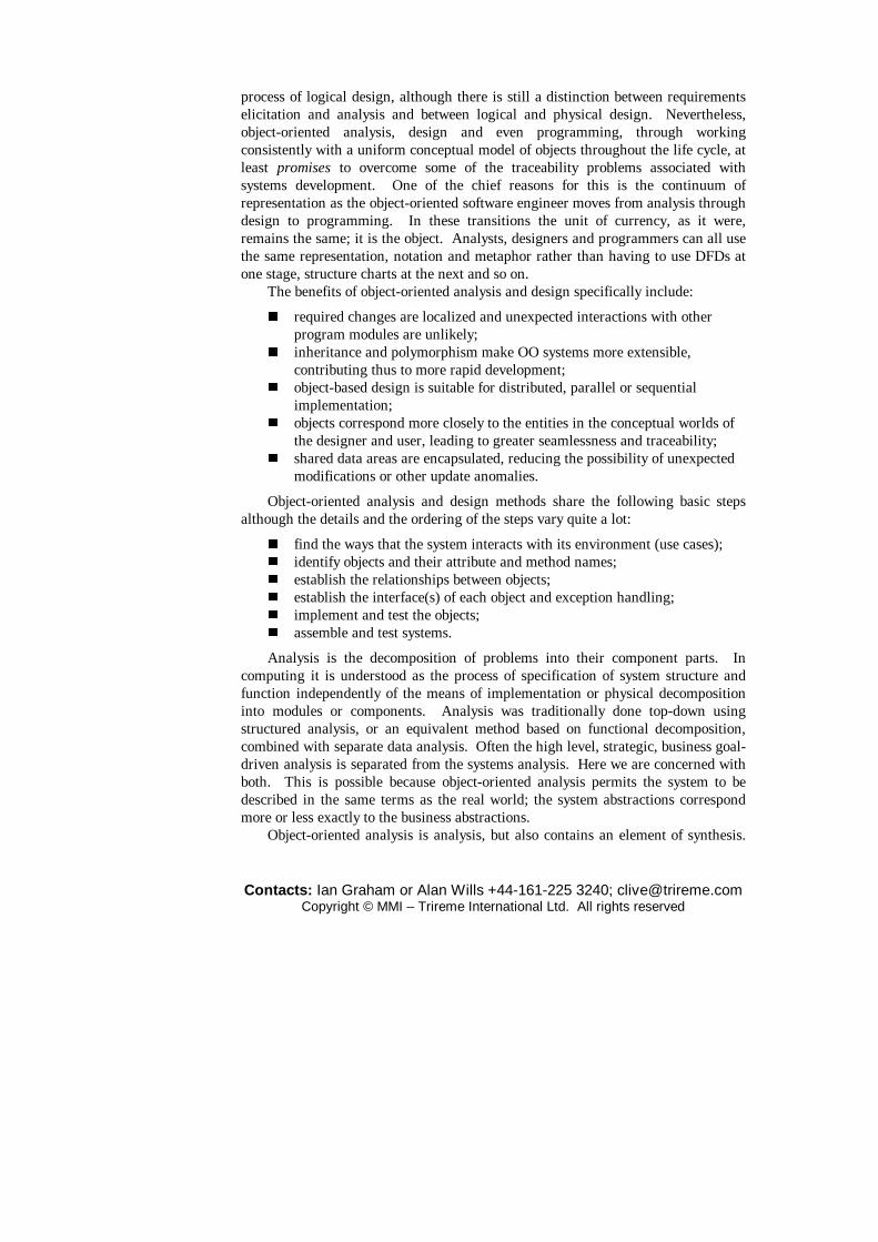
Object-oriented analysis and design methods share the following basic steps although the details and the ordering of the steps vary quite a lot:
� find the ways that the system interacts with its environment (use cases); � identify objects and their attribute and method names; � establish the relationships between objects; � establish the interface(s) of each object and exception handling; � implement and test the objects; � assemble and test systems.
Analysis is the decomposition of problems into their component parts. In computing it is understood as the process of specification of system structure and function independently of the means of implementation or physical decomposition into modules or components. Analysis was traditionally done top-down using structured analysis, or an equivalent method based on functional decomposition, combined with separate data analysis. Often the high level, strategic, business goal-driven analysis is separated from the systems analysis. Here we are concerned with both. This is possible because object-oriented analysis permits the system to be described in the same terms as the real world; the system abstractions correspond more or less exactly to the business abstractions.
Object-oriented analysis is analysis, but also contains an element of synthesis.
Contacts: Ian Graham or Alan Wills +44-161-225 3240; [email protected] Copyright © MMI – Trireme International Ltd. All rights reserved
Abstracting user requirements and identifying key domain objects are followed by the assembly of those objects into structures of a form that will support physical design at some later stage. The synthetic aspect intrudes precisely because we are analysing a system, in other words imposing a structure on the domain. This is not to say that refinement will not alter the design; a well-decoupled design can be considerably different from a succinct specification model.
There is a rich theory of semantic data modelling going far beyond the normal use of ER diagrams. This theory encompasses many of the concerns of object-orientation such as inheritance and abstract types. It also illuminates our understanding of relationships or associations between entities. Much of this work has been ignored by workers in object technology and in AI as thoroughly as these two areas have ignored each other.
Early OO analysis methods
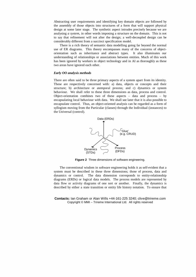
There are often said to be three primary aspects of a system apart from its identity. These are respectively concerned with: a) data, objects or concepts and their structure; b) architecture or atemporal process; and c) dynamics or system behaviour. We shall refer to these three dimensions as data, process and control. Object-orientation combines two of these aspects – data and process – by encapsulating local behaviour with data. We shall see later that it is also possible to encapsulate control. Thus, an object-oriented analysis can be regarded as a form of syllogism moving from the Particular (classes) through the Individual (instances) to the Universal (control).
Data (ERDs)
ProcessDynamics(STDs) (DFDs)
‘Glue’(e.g. CRUD)
Figure 2 Three dimensions of software engineering.
The conventional wisdom in software engineering holds it as self-evident that a system must be described in these three dimensions; those of process, data and dynamics or control. The data dimension corresponds to entity-relationship diagrams (ERDs) or logical data models. The process models are represented by data flow or activity diagrams of one sort or another. Finally, the dynamics is described by either a state transition or entity life history notation. To ensure that

Contacts: Ian Graham or Alan Wills +44-161-225 3240; [email protected] Copyright © MMI – Trireme International Ltd. All rights reserved
these diagrams are consistent, structured methods usually insist that some cross-checking documents are created to ‘glue’ the model together. For example, to check the consistency of a model between the Entity-Relationship and Data-Flow views, a CRUD matrix might be constructed. CRUD stands for ‘Create, Read, Update, Delete’. These letters indicate which processes use which entities and how they are used. This approach creates a potentially enormous overhead in terms of documentation alone. However, it does ensure that all aspects of a system are covered – assuming the knowledge elicitation is not deficient. It also has the advantage that where two techniques are used to reach the same conclusion then, if the results agree, the level of confidence in them is raised.
Data-centred approaches to software engineering begin with the data model while process-oriented approaches start with DFDs or activity diagrams. Some real-time approaches begin with finite state machines or STDs, but this is unusual for commercial systems developers. One problem with state transition diagrams is that, while they may be fine for systems with a small number of states – as with controllers – they are hopeless for systems with large numbers of, or even continuous, states. An object with n Boolean attributes may have 2n states. Most commercial system objects have several, non-Boolean attributes. For this reason, it is necessary to focus on states that give rise to data changes significant to the business. This means that both the states and their related changes must be apprehended at the same time. The solution is to partition state space into chunks corresponding to significant predicates and viewpoints. For example, the anaesthetist’s statechart for Person includes states {awake, asleep, dead}; the registrar’s has {single, married, divorced, widowed, deceased}; the accountant’s has {solvent, insolvent}. Each of these statecharts are simultaneously valid. But, of course, the partitioning can be regarded as subjective and care is needed.
Looking at early object-oriented analysis methods, certain things were noticeable. Some, such as Coad (Coad and Yourdon, 1990, 1991, 1991a) were simple but lacked support for describing system dynamics. Some such as OMT (Rumbaugh et al., 1991) and Shlaer-Mellor were richer, but very complex to learn. Methods like OMT also offered little to help express business rules and constraints. Embley’s OSA (Embley et al., 1992) and Martin and Odell’s (1992) synthesis of IE with Ptech were slightly simpler approaches. OSA allowed the analyst to write constraints on the diagrams as a sort of afterthought. None supported rules and you searched in vain for advice on how to combine the products of the three separate models into a coherent single model, though OMT did provide more help than others in this respect. An attempt to address some of these weaknesses in these otherwise attractive methods led to the SOMA method. SOMA combined a notation for object-oriented analysis with knowledge-based systems style rules for describing constraints, business rules, global system control, database triggers and quantification over relationships (e.g. ‘all children who like toys like each other’). It also addressed in this way issues of requirements engineering not addressed by other methods. SOMA was also unique in supporting fuzzy generalization, which

Contacts: Ian Graham or Alan Wills +44-161-225 3240; [email protected] Copyright © MMI – Trireme International Ltd. All rights reserved
is important for requirements specification in some domains such as enterprise modelling and process control, though unfashionable in many software engineering circles
As the discipline has matured a purer object-oriented focus has meant that mature modern methods dispense with DFDs, constructing state models for individual objects. However, they also build models of interactions between a system and its users and external devices, usually in the form of use cases.
2.1 Responsibility-driven versus data-driven approaches
It is often said that data are more stable than functions and so data-centred approaches are to be preferred in most cases. However, one of the greatest dangers in adopting a method based too much on structured techniques is that of data-driven design. Two software engineers at Boeing (Sharble and Cohen, 1994) conducted an experiment with internal trainees with similar backgrounds. One group was taught the data-driven Shlaer/Mellor method of object-oriented analysis – a method consciously and deeply rooted in traditional entity-relationship modelling – while the other group was instructed in the Responsibility Driven Design techniques of Wirfs-Brock et al. (1990). The two groups were then asked to design a simplified control application for a brewery. The Shlaer-Mellor group produced a design wherein most of the classes represented static data stores while one class accessed these and encapsulated the control rules for most of the application: in much the same style as a main{} routine in C would do. The other group distributed the behaviour much more evenly across their classes. It was seen that this latter approach produced far more reusable classes: classes that could be unplugged from the application and used whole. It also demonstrated vividly that the method you use can influence the outcome profoundly. It is our firm conviction that data-driven methods are dangerous in the hands of the average developer and especially in the hands of someone educated or experienced in the relational tradition. Furthermore, We hold that the approach taken to requirements engineering can have a huge influence.
The study by Sharble and Cohen shows convincingly that data-driven methods do influence the thinking of designers and that they tend to produce un-reusable classes as a consequence. The usual effects are that:
� behaviour is concentrated in controller objects that resemble main routines; this makes systems much harder to maintain due to the amount of knowledge that these controllers store about other objects;
� other objects have few operations and are often equivalent to normalized database tables: not reflective therefore of sound object-oriented design.
In our commercial practice we insist upon or encourage responsibility-driven design and analysis. We will be concerned throughout this text to emphasize this in all we do, just as we shall stress adherence to the basic principles of object technology:

Contacts: Ian Graham or Alan Wills +44-161-225 3240; [email protected] Copyright © MMI – Trireme International Ltd. All rights reserved
encapsulation and inheritance. This is not the pedantic reaction of a purist but a stance of immense practical significance.
2.2 Translational versus elaborational approaches
Another important way in which we may classify object-oriented methods is as either translational or elaborational. Methods like Booch, OMT and RUP are evangelistically elaborational. They treat the passage from specification to implementation as a matter of creating an initial model and then adding more and more detail (elaborating) until eventually we press a button and the compiled code pops out.
Translational approaches, among which Shlaer-Mellor was the paradigm, regard the process as a sequence of separate models together with a procedure for linking them and translating from one to the next. Thus we can use the most appropriate modelling techniques and viewpoints at each stage of our thinking about the problem but still guarantee seamlessness and traceability. Catalysis and SOMA fall inter alia into this camp and the next section will exemplify the approach.
3 Object-oriented analysis and design using UML
The Unified Modelling Language (UML) is probably the most widely known and used notation for object-oriented analysis and design. It is the result of the merger of several early contributions to object-oriented methods. In this section we use it to illustrate how to go about object-oriented analysis and design.
3.1 Types and classes
The first thing we need to know is how to represent objects. Figure 3 shows how classes and instances are represented. Unfortunately, UML does not distinguish adequately between types and classes notationally; but we can add the stereotype «type» to the class icon to show the difference. Stereotypes are tags that can be added to objects to classify them in various ways. This useful idea was originally proposed by Wirfs-Brock and McKean (1996) but in the current version of UML (1.4) a class is allowed only one stereotype, which rather destroys their point. CASE tools then use the stereotype to render the object graphically, as we shall see later. We are convinced, with the majority of methodologists, that future versions of UML will permit multiple stereotypes and will assume it is so in this text. Users of current CASE tools can use free-text notes to do this. Notes are also illustrated in Figure 3. Notice that instance names are always underlined;

Contacts: Ian Graham or Alan Wills +44-161-225 3240; [email protected] Copyright © MMI – Trireme International Ltd. All rights reserved
otherwise the notation for an instance is exactly the same as that for a class (type). A stereotype indicates a variation in the way the item should be interpreted,
dealt with by tools, and presented. Standard stereotypes also include: «interface», «type» and «capsule». Stereotypes can be added to classes, associations, operations, use cases, packages, and so on. Actors are just objects, tagged with the «actor» stereotype. Most tools just use the stereotypes to display different icons; e.g. pin men. Stereotypes make the language extensible, adding extra meaning to the basic pieces of syntax, but to preserve the communicability of models please consult your friendly, local methodologist before inventing more.
In approaching object-oriented analysis we need to deal first with types and only during design is it appropriate to think of classes. Therefore, rather than use the stereotype, we interpret the class icon as a type unless otherwise noted.

Contacts: Ian Graham or Alan Wills +44-161-225 3240; [email protected] Copyright © MMI – Trireme International Ltd. All rights reserved
Book
This is a type too:drawn in its shortform.
BookTitle
nameauthor: Person(0,*)publisherRRP: Money(0,1)
number-in-stock
This is a type.
operations
Attributes &associations
Middlemarch: BookTitle Middlemarch: BookTitle
Name = “Middlemarch”author: Person(0,*) = “George Eliot”publisher = “Penguin”RRP: Money(0,1) = 5.00
This is an instanceof the same type
… and so is this,with more detail.
Figure 3 Types and their instances. We have adopted the convention that classes (which are collections of
instances) are named in the plural, while types (which represent a single concept) are named in the singular. It should also be noted that rôles, such as the rôle of being an employee, are not the same as types or classes. The reason is that in object-oriented programming an instance belongs to its class forever; whereas a person can stop being an employee – on retirement say.
UML has no adequate distinction for rôles: although the short form shown in
Contacts: Ian Graham or Alan Wills +44-161-225 3240; [email protected] Copyright © MMI – Trireme International Ltd. All rights reserved
Figure 3 is the official usage, it is so useful for type diagrams as to make the restriction intolerable. We therefore usually model rôles as separate objects and indicate rôles with the stereotype «role» when the context so demands.
List
n:type
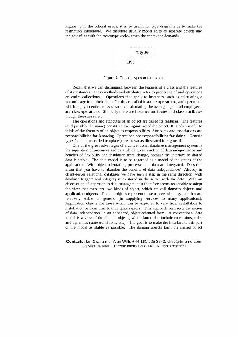
Figure 4 Generic types or templates. Recall that we can distinguish between the features of a class and the features
of its instances. Class methods and attributes refer to properties of and operations on entire collections. Operations that apply to instances, such as calculating a person’s age from their date of birth, are called instance operations, and operations which apply to entire classes, such as calculating the average age of all employees, are class operations. Similarly there are instance attributes and class attributes though these are rarer.
The operations and attributes of an object are called its features. The features (and possibly the name) constitute the signature of the object. It is often useful to think of the features of an object as responsibilities. Attributes and associations are responsibilities for knowing. Operations are responsibilities for doing. Generic types (sometimes called templates) are shown as illustrated in Figure 4.
One of the great advantages of a conventional database management system is the separation of processes and data which gives a notion of data independence and benefits of flexibility and insulation from change, because the interface to shared data is stable. The data model is to be regarded as a model of the statics of the application. With object-orientation, processes and data are integrated. Does this mean that you have to abandon the benefits of data independence? Already in client-server relational databases we have seen a step in the same direction, with database triggers and integrity rules stored in the server with the data. With an object-oriented approach to data management it therefore seems reasonable to adopt the view that there are two kinds of object, which we call domain objects and application objects. Domain objects represent those aspects of the system that are relatively stable or generic (in supplying services to many applications). Application objects are those which can be expected to vary from installation to installation or from time to time quite rapidly. This approach resurrects the notion of data independence in an enhanced, object-oriented form. A conventional data model is a view of the domain objects, which latter also include constraints, rules and dynamics (state transitions, etc.). The goal is to make the interface to this part of the model as stable as possible. The domain objects form the shared object

Contacts: Ian Graham or Alan Wills +44-161-225 3240; [email protected] Copyright © MMI – Trireme International Ltd. All rights reserved
model. Most interaction between components is via this model. We can go further and distinguish interface objects which are those whose sole raison d’etre is to enable communication, either with humans or with other systems and devices.
As an example of these distinctions in most business domains, Products and Transactions are unarguably domain objects, while DiscountCalculators might be a special application object. Classes like Sensors and InputValidators are likely to be interface objects.
These three categories can be regarded as stereotypes. Other stereotypes that are sometimes useful include controllers, co-ordinators, information holders and service providers. As Wirfs-Brock and McKean (1996) point out, such classifications are intentional oversimplifications to be refined during analysis and design.
Attribute facets
The type icon shows lists of associations and operations. Associations are attributes that refer to other types. There are two ways of interpreting them: one can either think of them as shorthand for their corresponding get and set operations or as providing the vocabulary with which the type can be discussed. As shown by Wills (2001) the latter interpretation is the best one for component or system specification, and the associations can then provide the basis for part of the test harness. These viewpoints are both useful in different contexts as we shall see. However, when we come to requirements analysis it is seen that a pointer viewpoint is often more valuable. Attributes are associations to more primitive types that are often left unspecified (such as String or Integer) and that we probably would not include on a structure diagram. What is ‘primitive’ is a rather subjective decision so that, technically, there is no distinction between attributes and associations.
UML allows classes to be tagged with extra information using the notation {tag=value}. The most useful tags include the following:
� description = descriptive text � keyword = classification keyword; e.g. botanical, etc. � object_classification = domain|application|interface � stereotype = additional stereotype; e.g. deferred, rôle, etc.
Abstract classes are named in italics. In specification, when we are talking about types rather than classes, the notion of ‘abstract’ does not, of course, make sense.
UML supports the following annotations to, or facets of, associations:
� default (or initial) value (name:Type=expression) � visibility prefix (+ = public, – = private, # = protected)
We would use notes or naming conventions to add additional facets of the following types:
� An attribute may have a list of allowed values (if it is of enumeration type) and a query preface (text used to preface any query on the attribute).

Contacts: Ian Graham or Alan Wills +44-161-225 3240; [email protected] Copyright © MMI – Trireme International Ltd. All rights reserved
� An attribute may be declared as a state variable that represents one of a number of enumerated states that the object may occupy.
� Association types are qualified as either {set}, {bag}, {ordered set} or {list}.
� Attributes can be variable/fixed/common/unique. Fixed means that the value may not change during the lifetime of the object. Different instances may have different values and we need not know what these values are. Variable is the opposite of fixed and is the default. Common attributes require that all instances have the same value, again without necessarily knowing what it is. Unique attributes are the opposite of common ones; each instance has a different value. A well-known example is a primary key in a database table. The default is neither common nor unique. The notation is one of the following: {variable}, {fixed}, {common}, {unique}, {fixed,common}, {fixed,unique}, {variable,common}, {variable,unique}.
� Security level may be specified. � Ownership may be specified with a tagged value. � Null values may be permitted or not. If not, the facet NON-NULL is set
true. For associations this is shown by a minimal cardinality of 1; e.g. WorksFor: Dept (1,n).
� Valid range constraints may be specified; e.g. age > 16. � $ before an attribute name indicates a class attribute. Its absence indicates
an instance attribute. A class attribute is a property of a whole collection of the class’s instances such as the maximum height of People. An instance attribute may have a different value for each instance such as the height of a person.
� × before an attribute name indicates that it cannot inherit its value. � / before an attribute name indicates a derived (i.e. inherited) attribute.
Operations are the specifications of an object’s methods. UML supports the following facets of operations:
� visibility (public = + , private = – , protected = #) � protocol and return type (name(arg1:Type, ..., argN:Type):Type
These can also be used to specify the visibility of packages. We will see later that additional facets, such as pre-conditions, are essential.
3.1 Object structures
The next thing we may wish to do is illustrate how objects relate to each other graphically. There are four principal ways in which objects interact. The most primitive of these is association, which indicates that a type is specified in terms of another type.

Contacts: Ian Graham or Alan Wills +44-161-225 3240; [email protected] Copyright © MMI – Trireme International Ltd. All rights reserved
Associations
UML shows associations using the notation given in Figure 5. The rôlenames can be regarded as labels for the cardinality constraints or as attributes of the type furthest away from where they are written. For example, holder can be thought of as an attribute of Account, constrained to hold between 1 and 2 values of type Customer.
CustomerBranchBank
Account
hqbranches 1
0..*holder 1,2
1..*
11..*
types
rôlename
cardinality
association
Figure 5 Associations in UML. When an association has interesting properties in its own right it should be
represented as a new type with the appropriate attributes and two new associations to the types it originally connected. For example, the association married-to between the types Man and Woman would be a plain vanilla association in an HR system but needs to be a type for a wedding registration system, with attributes including the people involved, the date of the marriage and so on. UML has a special notation for such ‘association classes’ but it is entirely redundant and so we will not use it (see Appendix C if you are interested).
Association types should not be introduced merely to remove many-to-many relationships as one would do during relational database design. They should only be used where they can be given meaningful names. A counter-example would be the relationship between products and regulations.
Converting associations into types can also be used to distinguish between rôles and players: the types that play the rôles. Figure 6 shows a set of transformations or refinements of the same model to illustrate the point. Notice that the notion of having a job can be reified into a type Job to allow the capture of work-related information. Converting this type back into an association allows us to be explicit about the rôles involved. This is rarely a good idea during specification but it is useful to know that it is possible, because at design time it may indicate how to design a class representing a plug-point.
Graham et al. (1997a) showed that bi-directional associations of the kind depicted in Figures 5 and 6 violate encapsulation and thereby compromise reuse. This kind of diagram is adequate for sketching out preliminary models and

Contacts: Ian Graham or Alan Wills +44-161-225 3240; [email protected] Copyright © MMI – Trireme International Ltd. All rights reserved
discovering the vocabulary of the domain but when documenting reusable components it is preferable to think of associations as one-directional pointers corresponding to the rôlenames in the figure. The reason for this will become even clearer when we discuss invariants.
Company
Person
Employee
1
1
0..*
0..*
Employer1
1
worksFor
Company
Person
Job
1
1
*
*
Company
Person
*
*
worksFor
Figure 6 Distinguishing rôles and players. We already have the notion of the interface to an object containing an attribute
and its facets. We can view associations as (generalized) attributes. In this sense an attribute contains zero or more values of a nominated type; an association stores values of a nominated user defined (or library) type. The only difference is that attributes point at ‘primitive’ types. What is primitive is up to the analyst and a key criterion for making this decision is whether the type (class) should appear on the class model diagrams.
Typical associations in an HR application might include ones that show that employees must work for exactly one department while departments may employ zero or more employees. These could be shown as follows.
worksIn: Dept(1,1) is an attribute of Employee. employs: (Employee,0,n) is an attribute of Dept.
We regard attributes as split into two sorts: pure attributes and (attributes representing) associations. Technically, there is no difference between the two but the associations of pure attributes are not shown in association structure diagrams, mainly to avoid clutter. The default cardinality for a pure attribute is (0,1); if the attribute is non-null this should be shown as a facet.
This definition of associations is slightly different from that of methods and notations such as OMT, Shlaer-Mellor, Coad or UML. These view associations as external to objects and their metamodels require a new primitive to accommodate
Contacts: Ian Graham or Alan Wills +44-161-225 3240; [email protected] Copyright © MMI – Trireme International Ltd. All rights reserved
them. This shows up most clearly when bi-directional associations are used. As we have seen, one of the two basic and characteristic features of object-
orientation is the principle of encapsulation. This says that objects hide the implementation of their data structures and processing, and are used only via their interface. An object-oriented model uses object types to represent all concepts and divides these types (or their implementations as classes) into a public interface representing the type’s responsibilities and an implementation that is hidden completely from all other parts of the system. The advantages of this are that it localizes maintenance of the classes and facilitates their reuse via calls to their interfaces alone. Modifications to classes are avoided by creating specialized subclasses that inherit basic responsibilities and can override (redefine) them and add new ones.
Bi-directional associations violate encapsulation. Stating that class A is associated with class B in some way or other is a statement of knowledge that concerns both classes. There are three obvious approaches to storing this knowledge:
� If the knowledge is separated from either class then we must return to a system of first- and second-class object types such as the one that plagued semantic data modelling. This means that, when we reuse either A or B, we have to have knowledge that is external to both of them in order to ensure that important coupling information is carried into the new system. Since this knowledge is not part of the classes it is quite conceivable that it could be lost, forgotten or overlooked by a hasty developer.
� Alternatively, we could place the knowledge inside one of the object types, A say. This will not work either, because now B will have lost track of its coupling with A and could not be reused successfully where this coupling was relevant.
� Finally, we could store the knowledge in both A and B. This last approach leads to the well-known problems of maintaining two copies of the same thing and cannot usually be tolerated.
Thus, separating objects from relationships violates encapsulation and compromises reuse. However, we will demonstrate later how the knowledge can indeed be split between the two types without loss of integrity, using invariants encapsulated in the objects.
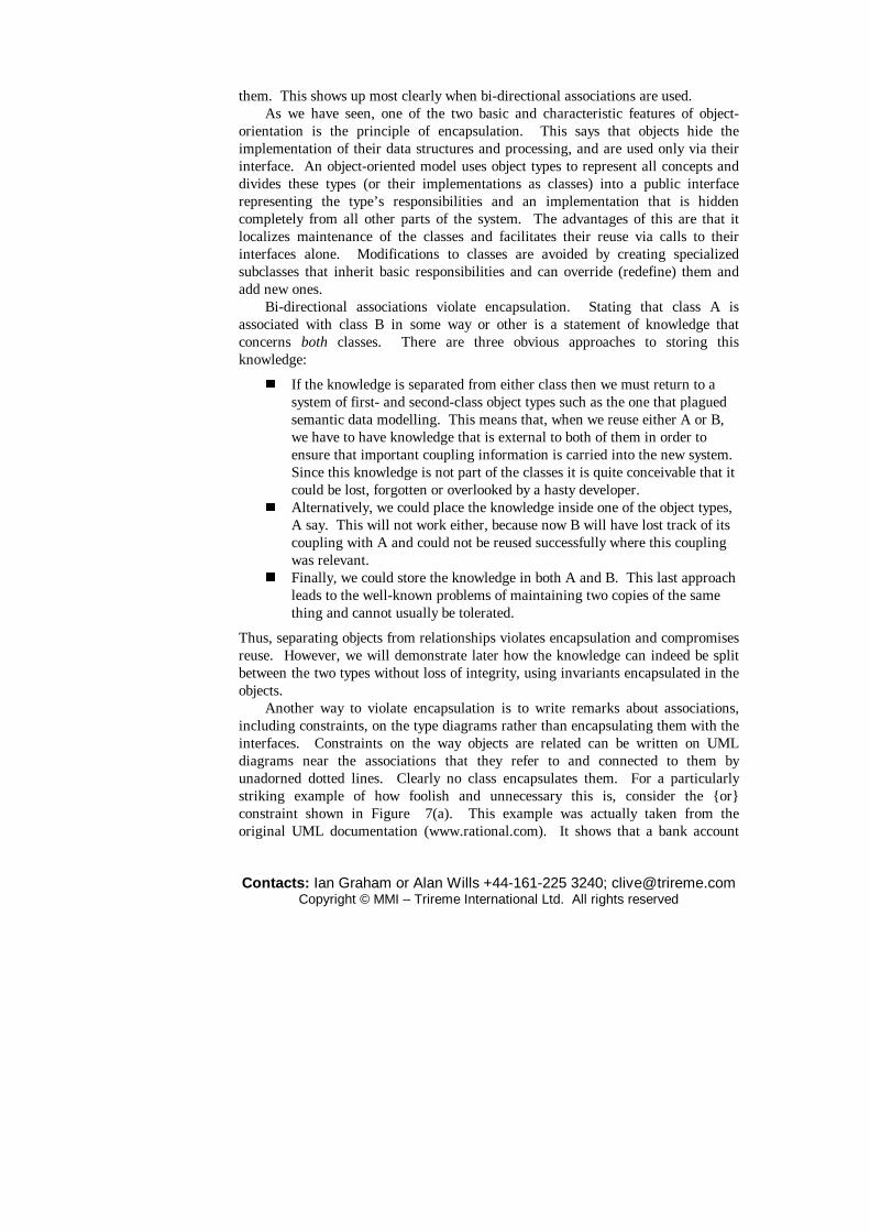
Another way to violate encapsulation is to write remarks about associations, including constraints, on the type diagrams rather than encapsulating them with the interfaces. Constraints on the way objects are related can be written on UML diagrams near the associations that they refer to and connected to them by unadorned dotted lines. Clearly no class encapsulates them. For a particularly striking example of how foolish and unnecessary this is, consider the {or} constraint shown in Figure 7(a). This example was actually taken from the original UML documentation (www.rational.com). It shows that a bank account
Contacts: Ian Graham or Alan Wills +44-161-225 3240; [email protected] Copyright © MMI – Trireme International Ltd. All rights reserved
can be held by a person or an organization, but not by both.
Account
Corporation
Person
{or}
Account
CorporationPerson
LegalEntity
(a)
(b)
Figure 7 (a) A UML constraint violating encapsulation; (b) how appropriate use of polymorphism makes the constraint unnecessary.
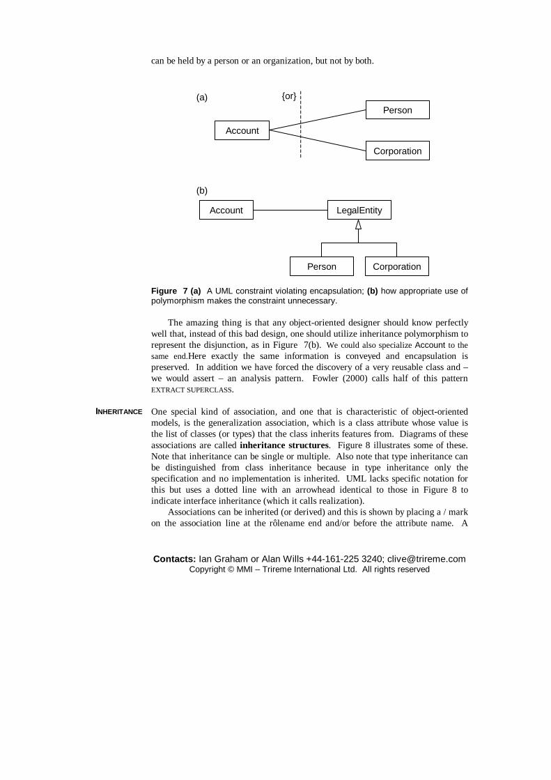
The amazing thing is that any object-oriented designer should know perfectly well that, instead of this bad design, one should utilize inheritance polymorphism to represent the disjunction, as in Figure 7(b). We could also specialize Account to the same end.Here exactly the same information is conveyed and encapsulation is preserved. In addition we have forced the discovery of a very reusable class and – we would assert – an analysis pattern. Fowler (2000) calls half of this pattern EXTRACT SUPERCLASS. One special kind of association, and one that is characteristic of object-oriented models, is the generalization association, which is a class attribute whose value is the list of classes (or types) that the class inherits features from. Diagrams of these associations are called inheritance structures. Figure 8 illustrates some of these. Note that inheritance can be single or multiple. Also note that type inheritance can be distinguished from class inheritance because in type inheritance only the specification and no implementation is inherited. UML lacks specific notation for this but uses a dotted line with an arrowhead identical to those in Figure 8 to indicate interface inheritance (which it calls realization).
Associations can be inherited (or derived) and this is shown by placing a / mark on the association line at the rôlename end and/or before the attribute name. A
INHERITANCE
Contacts: Ian Graham or Alan Wills +44-161-225 3240; [email protected] Copyright © MMI – Trireme International Ltd. All rights reserved
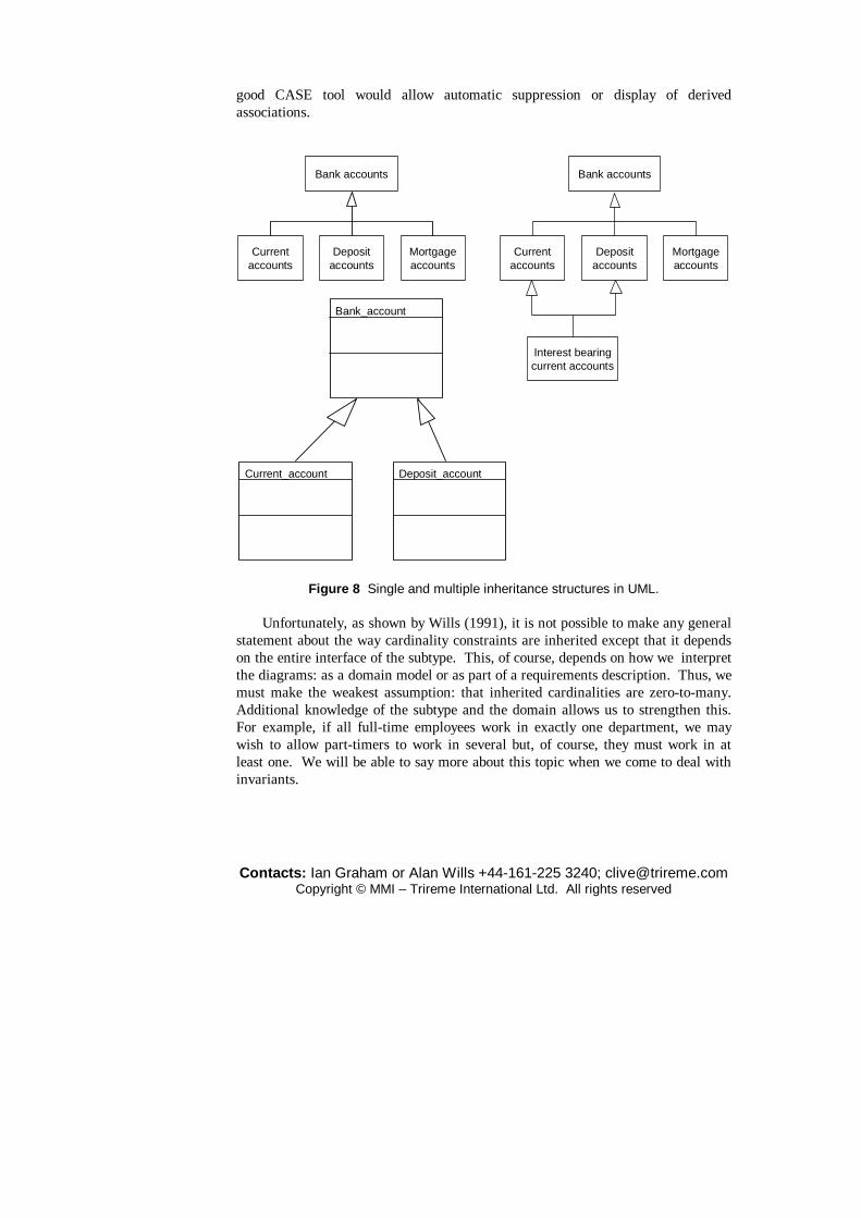
good CASE tool would allow automatic suppression or display of derived associations.
Bank accounts
Mortgageaccounts
Depositaccounts
Currentaccounts
Interest bearingcurrent accounts
Bank accounts
Mortgageaccounts
Depositaccounts
Currentaccounts
Bank_account
Current_account Deposit_account
Figure 8 Single and multiple inheritance structures in UML.
Unfortunately, as shown by Wills (1991), it is not possible to make any general statement about the way cardinality constraints are inherited except that it depends on the entire interface of the subtype. This, of course, depends on how we interpret the diagrams: as a domain model or as part of a requirements description. Thus, we must make the weakest assumption: that inherited cardinalities are zero-to-many. Additional knowledge of the subtype and the domain allows us to strengthen this. For example, if all full-time employees work in exactly one department, we may wish to allow part-timers to work in several but, of course, they must work in at least one. We will be able to say more about this topic when we come to deal with invariants.
Contacts: Ian Graham or Alan Wills +44-161-225 3240; [email protected] Copyright © MMI – Trireme International Ltd. All rights reserved
Aggregation and Composition
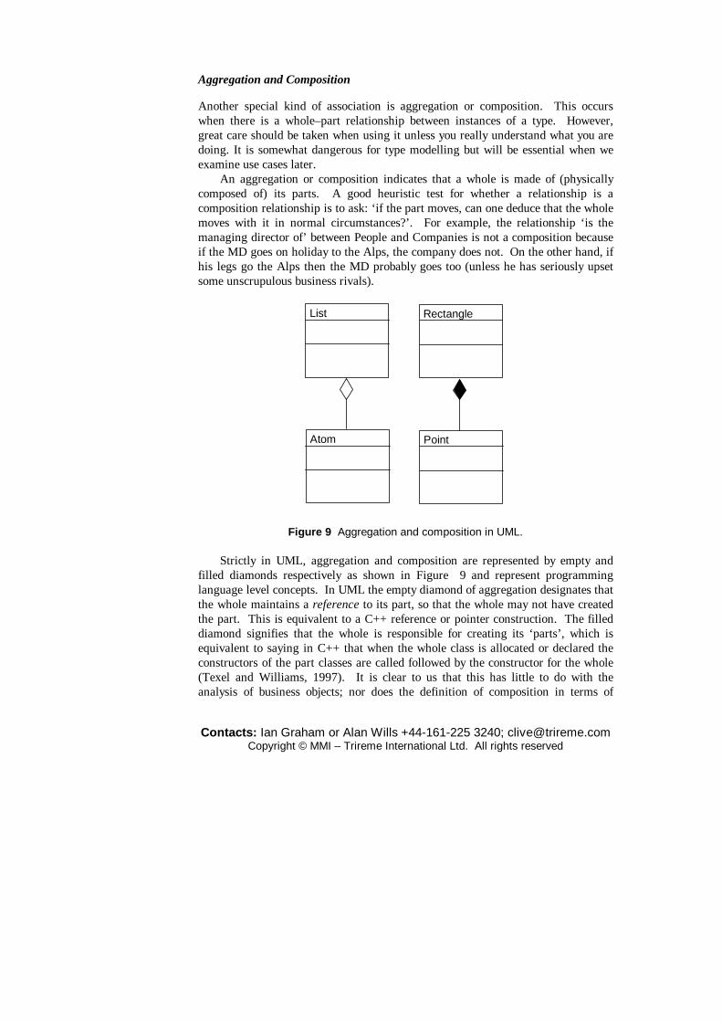
Another special kind of association is aggregation or composition. This occurs when there is a whole–part relationship between instances of a type. However, great care should be taken when using it unless you really understand what you are doing. It is somewhat dangerous for type modelling but will be essential when we examine use cases later.
An aggregation or composition indicates that a whole is made of (physically composed of) its parts. A good heuristic test for whether a relationship is a composition relationship is to ask: ‘if the part moves, can one deduce that the whole moves with it in normal circumstances?’. For example, the relationship ‘is the managing director of’ between People and Companies is not a composition because if the MD goes on holiday to the Alps, the company does not. On the other hand, if his legs go the Alps then the MD probably goes too (unless he has seriously upset some unscrupulous business rivals).
List
Atom
Rectangle
Point
Figure 9 Aggregation and composition in UML. Strictly in UML, aggregation and composition are represented by empty and
filled diamonds respectively as shown in Figure 9 and represent programming language level concepts. In UML the empty diamond of aggregation designates that the whole maintains a reference to its part, so that the whole may not have created the part. This is equivalent to a C++ reference or pointer construction. The filled diamond signifies that the whole is responsible for creating its ‘parts’, which is equivalent to saying in C++ that when the whole class is allocated or declared the constructors of the part classes are called followed by the constructor for the whole (Texel and Williams, 1997). It is clear to us that this has little to do with the analysis of business objects; nor does the definition of composition in terms of

Contacts: Ian Graham or Alan Wills +44-161-225 3240; [email protected] Copyright © MMI – Trireme International Ltd. All rights reserved
ownership and lifetime constraints on instances (Rumbaugh et al., 1999). We continue to use the terms composition and aggregation interchangeably for the common-sense notion of assembled components. The semantics of this notion were explored in detail by Odell (1994) whose argument may be summarized as follows.
Odell classifies composition relationships according to three decisions: whether they represent a structural relationship (configurational), whether the parts are of the same type as the whole (homeomeric) and whether the parts can be detached from the whole (invariant). This evidently factors APO into eight types. He then discusses six of them and names his different interpretations of composition as follows:
1. Component-integral (configurational, non-homeomeric and non-invariant). 2. Material (configurational, non-homeomeric and invariant). 3. Portion (configurational, homeomeric and non-invariant). 4. Place-area (configurational, homeomeric and invariant). 5. Member bunch (non-configurational, non-homeomeric and non-invariant). 6. Member-partnership (non-configurational, non-homeomeric and
invariant).
We will only use configurational, invariant composition. All other types of so-called composition (such as the manages relationship alluded to above) are handled by either associations or attributes (which are merely a special case of associations). What difference these distinctions make to the programmer is arguable. We like the idea of aggregation as a form of refinement: the constituents are what you find if you look closer.
1..m1..11..11..1
Hull MastRudderKeel
Yacht
Figure 10 Composition structure for a yacht. As with inheritance, composition is directional: it is improper for the part to
know what whole it belongs to because this would compromise reuse. To emphasize this we have adorned the example of a composite yacht in Figure 10 with arrowheads. Each composition link can have a cardinality constraint at the part end as also shown. If a similar constraint were to be used at the whole end, not only would this compromise encapsulation, but we would have to introduce a distinction between type level and instance level. We now think that a better way to handle this is to use Odell’s notion of a ‘power type’ (Martin and Odell, 1998). A
Contacts: Ian Graham or Alan Wills +44-161-225 3240; [email protected] Copyright © MMI – Trireme International Ltd. All rights reserved
power type is just a type whose instances are subtypes of another type. Types may have more than one power type corresponding to separate subtype discriminators. For example, if we divide employees into male and female subtypes we could create (slightly redundantly in this case) a power type called GenderType; but if we classify them according to job type a different (and perhaps more useful) power type may be used. Returning to aggregation, if we regard a bicycle as being composed of a frame and some (two?) wheels then a particular wheel can belong to only one bike. However, the type of wheel that it is can be fitted to several types of bike. This leads to the need to distinguish type level from instance level aggregation unless we introduce a power type corresponding to the catalogue description of the wheel: its WheelType. This phenomenon is referred to as ‘reflection’. The term is usually used when there is some facility to extend the model ‘at run time’; the idea is that the analyst defines a model in which there is a type of types, which can be used at run time to add new types, but over which relationships are nevertheless asserted in the base specification language.
Type BType C
Type A2
Type A1
Type A
Type B2Type B1
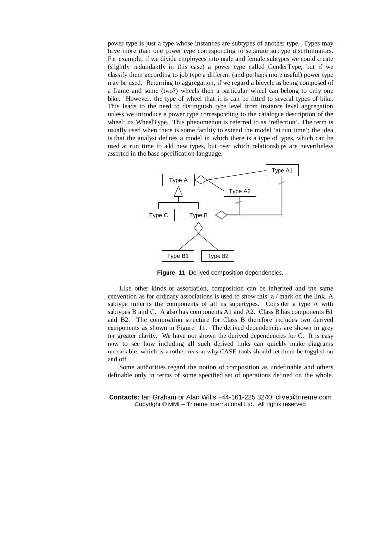
Figure 11 Derived composition dependencies. Like other kinds of association, composition can be inherited and the same
convention as for ordinary associations is used to show this: a / mark on the link. A subtype inherits the components of all its supertypes. Consider a type A with subtypes B and C. A also has components A1 and A2. Class B has components B1 and B2. The composition structure for Class B therefore includes two derived components as shown in Figure 11. The derived dependencies are shown in grey for greater clarity. We have not shown the derived dependencies for C. It is easy now to see how including all such derived links can quickly make diagrams unreadable, which is another reason why CASE tools should let them be toggled on and off.
Some authorities regard the notion of composition as undefinable and others definable only in terms of some specified set of operations defined on the whole.
Contacts: Ian Graham or Alan Wills +44-161-225 3240; [email protected] Copyright © MMI – Trireme International Ltd. All rights reserved
We recommend that composition is used sparingly in business object modelling it is absolutely essential when modelling actions as objects.
Depend-encies
UML also allows dependencies of arbitrary type between types and classes. These are shown by the labelled, dashed arrows. The label is a stereotype. The most usual and useful dependencies relate to interfaces and packages and we shall return to them later in those contexts.
Usage
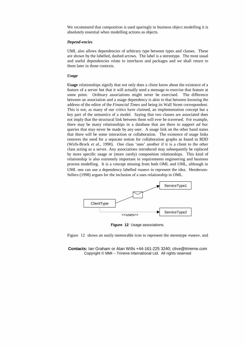
Usage relationships signify that not only does a client know about the existence of a feature of a server but that it will actually send a message to exercise that feature at some point. Ordinary associations might never be exercised. The difference between an association and a usage dependency is akin to that between knowing the address of the editor of the Financial Times and being its Wall Street correspondent. This is not, as many of our critics have claimed, an implementation concept but a key part of the semantics of a model. Saying that two classes are associated does not imply that the structural link between them will ever be traversed. For example, there may be many relationships in a database that are there to support ad hoc queries that may never be made by any user. A usage link on the other hand states that there will be some interaction or collaboration. The existence of usage links removes the need for a separate notion for collaboration graphs as found in RDD (Wirfs-Brock et al., 1990). One class ‘uses’ another if it is a client to the other class acting as a server. Any associations introduced may subsequently be replaced by more specific usage or (more rarely) composition relationships. This kind of relationship is also extremely important in requirements engineering and business process modelling. It is a concept missing from both OML and UML, although in UML one can use a dependency labelled «uses» to represent the idea. Henderson-Sellers (1998) argues for the inclusion of a uses relationship in OML.
ClientType
ServiceType2
ServiceType1
<<uses>>
Figure 12 Usage associations. Figure 12 shows an easily memorable icon to represent the stereotype «uses», and

Contacts: Ian Graham or Alan Wills +44-161-225 3240; [email protected] Copyright © MMI – Trireme International Ltd. All rights reserved
the more usual notation.
3.2 Using use cases to discover types
So far we have seen how to describe and draw pictures of objects but little has been said about how to go about discovering them. The most popular technique starts with a set of use cases that describe how a system interacts with its environment: typical interactions involving its users.
sale
Purchasers Vendors
use case
class of agent
Thing
Post-condition: A thing is transferredfrom Vendor’s ownership to that of thePurchaser; price is transferred from thePurchaser’s pocket to the Vendor’s till.
Figure 13 Use cases and the types they refer to. Catalysis introduced the idea of actions, which generalize both use cases and
operations. An action is any goal-oriented collaboration, activity, task, operation or job connecting agents in a business, system or project. When specifying systems, the most interesting actions are use cases. A use case is a goal-oriented collaboration between a system and an actor; where an actor is a user adopting a rôle. Such a ‘user’ can be a device or component as well as a person. An agent is anybody or anything adopting a rôle; as opposed to a user doing so. We regard agents and actors as objects, because they exhibit state and behaviour and have identity. If we know the initiator of a collaboration then we can think of a usage dependency as representative of the action. Consider the simple act of buying something illustrated in Figure 13. The ellipse represents an interaction between two agent instances which results in something changing ownership between them in return for money changing hands in the other direction. This is represented by an informal post-condition on the action written in the note illustrated. This post-condition only makes sense in terms of the objects it refers to: its parameters. In this case we have identified Thing as a type that must be included in our vocabulary and shown it on our initial drawing. Additionally, we have picked out some of the nouns in the post-condition. This is a very useful technique for inferring the type model from the use cases. We show candidate types in bold, with attributes

Contacts: Ian Graham or Alan Wills +44-161-225 3240; [email protected] Copyright © MMI – Trireme International Ltd. All rights reserved
underlined and potential associations italicized. We can see from this example that an action always results in a change of state
that can be expressed by a post-condition. Catalysis introduced the idea of illustrating this change using instance snapshots. We draw instances of the candidate types and their associations at a particular point in time, before the occurrence of the action. Then the result of applying the use case is expressed by showing which associations are deleted and added to the diagram. In Figure 14 the association between sock17 and the vendor is crossed out from the ‘before’ diagram (indicating deletion) and added to the ‘after’ diagram. Associations in after snapshots are shown by thick grey lines. Note also that the values of the pocket and till attributes are crossed out and replaced with new values.
jo:Purchaserpocket= £20 £18
Things‘R’Us:Vendortill= £200 £202
sock17:Thinggluepot1:Thingrock:Thing
box1:Thing jellyjar7:Thing
possessions possessions
Figure 14 An instance snapshot.
Any snapshot must conform to the type diagram associated with the use case it illustrates. Snapshots are useful as an aid to clear thinking during analysis and design. They represent instances of use cases. Although simple ones may be included in formal documentation, We usually recommend against this. After drawing them, the type model can usually be updated. Note in particular that neither the action post-condition nor the snapshots say anything about the sequence of events; they only describe the outcome, regardless of the precise sequence of events leading to it. This is important when we come to the design of reusable components because two components (or two business units) may implement the use case quite differently. The interface to a reusable component should only specify the outcome and the vocabulary, not the sequence of implementation operations that leads to that outcome.
Every action, and a fortiori every use case, has a name, a goal, a list of participants (usually two in business analysis) and a list of parameters: the objects involved (actively or passively) that are different from one occurrence of the use case to another. The goal represents its specification: the result(s) it achieves, and/or a condition that it maintains. There may also be a pre-condition: a statement defining under what conditions the use case makes sense. Thus, when documenting an action the following form is recommended:

Contacts: Ian Graham or Alan Wills +44-161-225 3240; [email protected] Copyright © MMI – Trireme International Ltd. All rights reserved
type name (parameters) pre-condition post-condition
For example, referring to Figure 13, we might write:
use case buy_thing (Purchaser, Vendor, Thing) pre: vendor owns the thing and purchaser can afford it post: vendor.possessions reduced by thing and purchaser.possessions increased by thing and vendor.till += thing.price and purchaser.pocket −= thing.price
We could even express this with full mathematical formality using UML’s Object Constraint Language (OCL) as follows:
use case buy_thing (Purchaser, Vendor, Thing) pre: vendor.possessions -> includes thing And purchaser.pocket >= thing.price post: vendor.possessions = vendor.possessions − thing and purchaser.possessions = purchaser.possessions + thing and vendor.till = vendor.till@pre + thing.price and purchaser.pocket = purchaser.pocket@pre – thing.price
In the above, the expression @pre refers to the value held by the attribute in the before state and ->includes indicates set membership. The + sign is an abbreviation for –>union (ditto the – sign mutatis mutandis). Another convention used here is inherited from Fusion (Coleman et al., 1994): if all the parameters have different types, their names are the same as the type names, but starting with lower case. The same convention is used for unlabelled associations. Using upper case means one is saying something about the type. Notice also that there is no attribute of Thing named price. The only purpose of the attributes is to provide a vocabulary for the action specifications.
OCL specifications are not to everyone’s taste and do not need to be used. But it is reassuring for those of us who work on high-integrity or safety-critical systems that such formality is possible. We will not use OCL very much in this text.
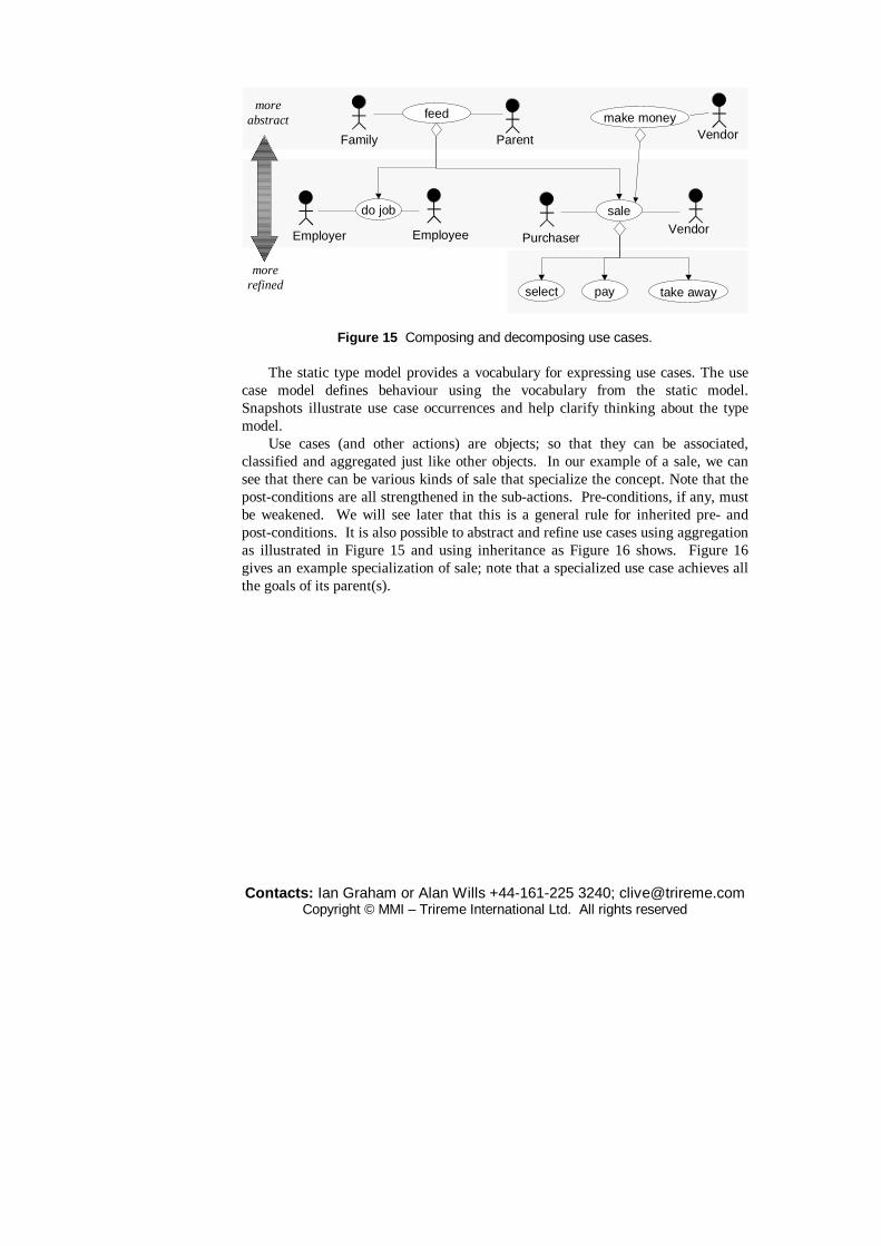
Contacts: Ian Graham or Alan Wills +44-161-225 3240; [email protected] Copyright © MMI – Trireme International Ltd. All rights reserved
sale
Purchaser
Vendor
feed
Family Parent
do job
EmployeeEmployer
select pay take away
make money
Vendor
moreabstract
morerefined
Figure 15 Composing and decomposing use cases. The static type model provides a vocabulary for expressing use cases. The use
case model defines behaviour using the vocabulary from the static model. Snapshots illustrate use case occurrences and help clarify thinking about the type model.
Use cases (and other actions) are objects; so that they can be associated, classified and aggregated just like other objects. In our example of a sale, we can see that there can be various kinds of sale that specialize the concept. Note that the post-conditions are all strengthened in the sub-actions. Pre-conditions, if any, must be weakened. We will see later that this is a general rule for inherited pre- and post-conditions. It is also possible to abstract and refine use cases using aggregation as illustrated in Figure 15 and using inheritance as Figure 16 shows. Figure 16 gives an example specialization of sale; note that a specialized use case achieves all the goals of its parent(s).

Contacts: Ian Graham or Alan Wills +44-161-225 3240; [email protected] Copyright © MMI – Trireme International Ltd. All rights reserved
sale
Purchaser Vendor
post price transferred from Purchaser to Vendor andThing transferred from Vendor to Purchaser
petrol sale
post Thing is a volume of Petrol
credit card sale
payment is bycredit card
prepay sale
price transfer occursbefore Thing transfer
Thing
moreabstract
morerefined
Figure 16 Generalizing and specializing use cases.
Figure 16 contains a deliberate faux pas, intended to illustrate a common error. It is quite wrong for the same inheritance arrow to be used to connect the completely incomparable notions of a petrol sale and a credit sale. We should show the two orthogonal hierarchies separately; each inheritance arrow corresponds to a discriminator such as ‘fuel type’ or ‘payment method’. Always ask yourself ‘what is the discriminator?’ when drawing a specialization diagram of any sort.
The left-to-right ordering in aggregation diagrams like Figure 15 does not imply any temporal sequence; the use cases could happen in any sequence, be repeated or be concurrent. However, we can add such information by creating associations between actions using «uses» dependencies. UML specifies two particular dependencies designated «include» (originally «uses») and «extend» (originally «extends»). However, since these are poorly and inconsistently defined and since «extend» violates encapsulation (Graham et al., 1997a) we will not use them in this tutorial. Our experience is that their use sows confusion and, besides, the standard object semantics that we have laid down for static models enables us to do everything without introducing additional terminology.
The goals of use cases provide the basis for building a test harness very early on in analysis, because they relate directly to the purpose and function of a system. This also facilitates eXtreme Programming (Beck, 2000).
Notice how the actors in the use case model correspond to types in the type model in our preliminary attempt. Also, if we regard the type model as providing the vocabulary for defining the use cases, we can see that this provides a link between two different kinds of UML diagram. It was a major innovation of Catalysis to show how the UML diagram types were related.

Contacts: Ian Graham or Alan Wills +44-161-225 3240; [email protected] Copyright © MMI – Trireme International Ltd. All rights reserved
make order(drum, order)
kim: Purchaser : Vendor
buy (flute)
buy (drum)
: Vendorkim: Purchaser
deliver(order.thing)
pay(order.price)
zoom in ondetail ofinteraction
: Sales : Distribution : Accounts
zoom in ondetail of instance
kim: Purchaser
make order(drum)notify order (order)
deliver (order.thing)pay (order.price)
Figure 17 Sequence diagrams and refinement. Just as snapshots help us visualize the type model, scenarios and sequence
diagrams help with the visualization of use cases. Scenarios are stories about how the business works. They can be written out in prose and this is often a useful thing to do. They describe typical sequences that occur when a use case is realized and can include variations on the basic sequence. They can be illustrated with UML sequence or collaboration diagrams of the kind shown in Figure 18 or, better, with the Catalysis-style sequence chart of Figure 17. The distinctive feature of the latter is the action-instances, each of which may touch more than two objects, and need not be directed.
UML sequence diagrams only describe OO programming messages, each with a receiver and sender. In both cases the vertical lines represent the instances of the types indicated above them and the horizontal lines represent actions that involve the instances that they connect. Both dimensions can be expanded to refine the analysis and provide more detailed steps and a finer scale; each event can be expanded to more detailed sequences and each object to more detailed objects. In the figure we see that one can zoom in on the details of the buy(drum) use case to show details of the vendor’s business process sequence. We can also zoom in on the vendor object to reveal details of his business organization as well. The trick is to choose the level and scale that you are working at: essential ‘my pay was credited to my account yesterday, so I went to get some cash today’; detail ‘to get money from your account, you insert your card into a cash machine, enter PIN, …’; grandiose ‘A good way of making money is to run a bank. Provide accounts with higher rates of interest in exchange for less accessibility. They should be able to get cash from the most accessible accounts at any time of day or night.’

Contacts: Ian Graham or Alan Wills +44-161-225 3240; [email protected] Copyright © MMI – Trireme International Ltd. All rights reserved
sue: Managertony: Secretary intray: WorkTray
1.2 *acceptApplication(ianApplic)
1.2.1 put(ianApplic)
ianApplic: Application
2.1 nextApplicn()
2.1.1 get()
1.1 new
instance creation
message
1 needJob()
2 needWorker()
return ianApplic
optional
ian: Person
stores ianApplic
repeated
ian: Person sue: Managertony: Secretary
intray: WorkTray
1.2 *acceptApplication(ianApplic)
1.2.1 put(ianApplic)
2 needWorker()
ianApplic: Application
2.1 intray.get()
2.1 nextApplicn()
2.1.1 get()
1 needJob( )“*” = repeated with other receiver instances
1.1 new
boss
1 intrayinstance creation
messageassociation
Figure 18 Sequence and collaboration diagrams. Sequence charts for scenarios help to identify the different participants in the
action and their interactions and to show the sequence of events. This helps with the conceptualization of the rôle of time and with understanding dependencies between instances. Sequence charts assist the designer in allocating instances among distributed system components and are often useful during testing. They also help with exploring interference between multiple use cases.
Notice that zooming is based on aggregation in the examples given above. Inheritance can also lead to refinements; so we could zoom from buy(drum) to buy(bodhran), which would involve the purchaser selecting a tipper and testing the goatskin for usefully melodious imperfections.
Refinement is one of the basic principles of Catalysis and aids traceability by linking specification level use cases and types to implementation interfaces and their vocabularies. Typically, the different levels of refinement will be contained in different implementation packages.
Sequence diagrams emphasize visualizing the allocation of responsibility: it is easy to shift tasks sideways. They are equivalent to collaboration diagrams which emphasize static relationships rather than temporal ones. Collaboration diagrams help you see what associations are being affected, and the dependencies between the objects (which, of course, you want to minimize). Sequence diagrams are good at
Contacts: Ian Graham or Alan Wills +44-161-225 3240; [email protected] Copyright © MMI – Trireme International Ltd. All rights reserved
illustrating the assignment of responsibilities but cannot express control flow variation well. Collaboration diagrams are better at showing associations and control flow. This helps us to think about better decoupling. Figure 18 shows a sequence diagram and its associated collaboration form. Arrows or lines joining the instances in the latter represent associations. Messages are indicated by the unattached arrows and their numbering indicates their calling sequence. Detailed as they look, collaboration diagrams still abstract from the precise details of implementation. In this case we see that the association between the manager and the work tray represents a poor design. S/he would be better to access these data through a secretarial service, which can be provided either by Tony or by an access function to a database. A change in the way the job-applications are stored would result in a change to both Secretary and Manager if they both access the Worktray. The moral is that we can reduce dependencies by assigning responsibilities properly; the collaborations help us understand how to assign responsibilities. Figure 18 also shows that collaboration diagrams can be used as snapshots.
3.3 Invariants and rulesets
In performing object-oriented analysis and building a model, a large number of lessons can be learnt from AI systems built using semantic nets and from semantic data modelling. Specifications that exhibit encapsulation of attributes and operations are all very well but do not necessarily contain the meaning intended by the analyst or the user. To reuse the specification of an object we should be able to read from it what it knows (attributes), what it does (operations), why it does it and how it is related to other objects’ interfaces. It is our position that this semantic content is partly contained in the structures of association, classification, composition and usage and by the assertions, invariants and rulesets which describe the behaviour.
The fact is that all semantics limit reuse, although they make it safer. For example, inheritance does so; and so does anything that makes the meaning of an object more specific. In system specification, both aspects are equally important and the trade-off must be well understood and managed with care, depending on the goals of the analysts and their clients.
One must also be aware of the need to decide whether rules belong to individual operations or to the object as a whole. There is no principled reason why operations cannot be expressed in a rule-based language. However, the distinction to be made here is not between the form of expression but the content of the rules. Rules that relate several operations do not belong within those operations and rules which define dependencies between attributes also refer to the object as a whole. Conversely, rules that concern the encapsulated state of the object belong within one of its operations. The most important kind of ‘whole object’ rules are control rules which describe the behaviour of the object as it participates in structures that it

Contacts: Ian Graham or Alan Wills +44-161-225 3240; [email protected] Copyright © MMI – Trireme International Ltd. All rights reserved
belongs to: rules to control the handling of defaults, multiple inheritance, exceptions and general associations with other objects.
The introduction of encapsulated rulesets was a novel aspect of SOMA. It enhances object models by adding a set of rulesets to each object. Thus, while an object is normally thought to consist of Identifier, Attributes and Operations, a SOMA object consists of Identifier, Attributes, Operations and Rulesets. Rulesets are composed of an unordered set of assertions and rules of either ‘if/then’ or ‘when/then’ form. This modelling extension has a number of interesting consequences, the most remarkable of which is that these objects – which are local entities – can encapsulate the rules for global system behaviour; rather as DNA is supposed to encapsulate the morpheme. A further consequence is that objects with rulesets can be regarded as intelligent agents for expert systems developments.
It is widely agreed that it is quite insufficient to specify only the attributes and operations (the signature) of an object. To specify the object completely we must say how these are allowed to interact with each other and what rules and constraints must be obeyed by the object as a whole to maintain its integrity as such. Some languages, such as Eiffel, and some methods, such as BON, Catalysis or Syntropy, achieve a partial solution by using assertions. Assertions in such systems are of two kinds: assertions about the operations and assertions about the whole object. The former are typically pre- and post-conditions while the latter are called class invariants. SOMA and Catalysis add invariance conditions to the operational assertions and SOMA generalizes class invariants to rulesets – which can be chained together to infer new information. There are also assertion facets representing attribute constraints. Here are the definitions:
Attribute assertions � Range constraints give limits on permissible values. � Enumeration constraints list permissible values. � Type constraints specify the class that values must belong to. Type
constraints are always present and generalize the former two cases.
Operational assertions � A pre-condition is a single logical statement that must be true before its
operation may execute. � A post-condition is a single logical statement that must be true after its
operation has finished execution. � An invariance condition is a single logical statement that must hold at all
times when its operation is executing. This is only of importance for parallel processing systems (including business process models). Invariance conditions were first introduced as part of SOMA (Graham, 1991a). Catalysis (D’Souza and Wills, 1999) distinguishes two kinds of invariance conditions: guarantee and rely clauses.

Contacts: Ian Graham or Alan Wills +44-161-225 3240; [email protected] Copyright © MMI – Trireme International Ltd. All rights reserved
� A rely clause states a pre-condition that must remain true throughout the execution of the operation it refers to. Should it be violated, the specification does not state what clients can expect as a result. The server is not responsible for maintaining the condition.
� A guarantee is a statement that the server must maintain as true throughout the execution of the operation.
The facets of an operation may include more than one assertion of any of these types. Assertions may be represented by state-transition diagrams as we shall see.
Object assertions and rulesets � A class invariant is a single (possibly quantified) logical statement about
any subset of the features of an object that must be true at all times (in Eiffel, which has direct support for invariants, this only applies to times when a method is not executing). Cardinality constraints on attributes are invariants. Invariants can also be called rules.
� A ruleset is an unordered set of class invariants (or rules) and assertions about attributes together with a defined inference régime that allows the rules to be chained together. External rulesets express second order information such as control strategy. Internal rulesets are (first order) sets of invariants. They may be written either in natural language, OCL or in an executable rule language.
� An effect is a post-condition that is conjoined with all other operation post-conditions of a type. An effect is usually of the form: (any change f(x, x@pre) ⇒ condition). Effects can be expressed as rules. They are useful for the designer of a supertype who wants to impose restrictions on the operations that may be invented by subtype specifiers.
The normal assumption behind the above definitions is that the logic to be used is standard first order predicate calculus (FOPC). We make no such assumption although FOPC is the usual default logic. Other logics that can be used include temporal, fuzzy, deontic, epistemic and non-monotonic logic. Each ruleset in a class determines its own logic locally, although it would be unusual to mix logics in the same class.
We have already seen the distinction between a type and a class: a type has no implementation. We can now distinguish between types and interfaces. An interface is a list of the messages that can be sent to an object with their parameters and return types. Depending on the interpretation, this may include the get and set operations on attributes. This concept is sometimes referred to as the signature of a type. A type on the other hand is a full specification including all the assertions that may be made about the type and its instances and all rulesets.
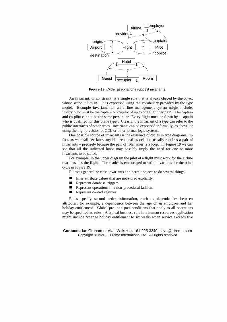
Contacts: Ian Graham or Alan Wills +44-161-225 3240; [email protected] Copyright © MMI – Trireme International Ltd. All rights reserved
Flight Pilot
captain
copilot
Airport
origin
destination
??
Airlineemployer
provider 11
?
Hotel
Guest Room
1 1
?
1occupier
Figure 19 Cyclic associations suggest invariants. An invariant, or constraint, is a single rule that is always obeyed by the object
whose scope it lies in. It is expressed using the vocabulary provided by the type model. Example invariants for an airline management system might include: ‘Every pilot must be the captain or co-pilot of up to one flight per day’, ‘The captain and co-pilot cannot be the same person’ or ‘Every flight must be flown by a captain who is qualified for this plane type’. Clearly, the invariant of a type can refer to the public interfaces of other types. Invariants can be expressed informally, as above, or using the high precision of OCL or other formal logic systems.
One possible source of invariants is the existence of cycles in type diagrams. In fact, as we shall see later, any bi-directional association usually requires a pair of invariants – precisely because the pair of rôlenames is a loop. In Figure 19 we can see that all the indicated loops may possibly imply the need for one or more invariants to be stated.
For example, in the upper diagram the pilot of a flight must work for the airline that provides the flight. The reader is encouraged to write invariants for the other cycle in Figure 19.
Rulesets generalize class invariants and permit objects to do several things:
� Infer attribute values that are not stored explicitly. � Represent database triggers. � Represent operations in a non-procedural fashion. � Represent control régimes.
Rules specify second order information, such as dependencies between attributes; for example, a dependency between the age of an employee and her holiday entitlement. Global pre- and post-conditions that apply to all operations may be specified as rules. A typical business rule in a human resources application might include ‘change holiday entitlement to six weeks when service exceeds five

Contacts: Ian Graham or Alan Wills +44-161-225 3240; [email protected] Copyright © MMI – Trireme International Ltd. All rights reserved
years’ as a rule in the Employee type. With rulesets the notation can cope with analysis problems where an active database is envisaged as the target environment.
Rules and invariants are used to make an object’s semantics explicit and visible. This helps with the description of information that would normally reside in a repository, such as business rules for the enterprise. It can also help with inter-operability at quite a low level. For example, if I have an object which computes cube roots, as a client of that object it is not enough to know its operations alone; I need to know that what is returned is a cube root and not a square root. In this simple case the solution is obvious because we can characterize the cube root uniquely with one simple rule: the response times itself twice is equal to the parameter sent. If this rule is part of the interface then all other systems and system components can see the meaning of the object from its interface alone, removing thus some of the complexities of repository technology by shifting it into the object model.
The rules which appear in the rule window may be classified into several, not necessarily exclusive, types, as follows.
� Business rules � Exception handling rules � Triggers � Control rules
Control rules
The last application of rulesets is by far and away the most esoteric. Object-oriented methods must obviously deal with multiple class inheritance. This extension must include provision for annotating the handling of conflict arising when the same attribute or operation is inherited differently from two parent objects. Of course, types compose monotonically so this problem doesn’t arise. This kind of discrimination can only be done with a class. One way to deal with it is to use rulesets to disambiguate multiple inheritance. One can then also define priority rules for defaults and demons. (A demon is a method that wakes up when needed; i.e. when a value changes, or is added or deleted.) That is, these rules can determine how to resolve the conflict that arises when an attribute inherits two different values or perhaps specify whether the default value should be applied before or after inheritance takes place or before or after a demon fires. They may also specify the relative priorities of inheritance and demons. As with attributes and operations, the interface of the object only displays the name of a ruleset. In the case of a backward chaining ruleset this might well include the name of the value being sought: its goal; e.g. If Route: needed SEEK Route:
Control rules are encapsulated within objects, instead of being declared globally. They may also be inherited and overridden (although the rules for this may be slightly complicated in some cases – see (Wills, 1991)). The benefit of this

Contacts: Ian Graham or Alan Wills +44-161-225 3240; [email protected] Copyright © MMI – Trireme International Ltd. All rights reserved
is that local variations in control strategy are possible. Furthermore, the analyst may inspect the impact of the control structure on every object – using a browser perhaps – and does not have to annotate convoluted diagrams to describe the local effects of global control. Genuinely global rules can be contained in a top level object, called something like ‘object’, and will be inherited by all objects that do not override them. Alternatively, we can set up global rules in a special ‘policy blackboard’ object. Relevant classes register interest in Policies, which broadcasts rule and status changes to registrants as necessary. This uses, of course, a publish and subscribe pattern. Just as state transition diagrams may be used to describe the procedural semantics of operations, so decision trees may be found useful in describing complex sets of rules.
Control rules concern the operations and attributes of the object they belong to. They do not concern themselves. Thus, they cannot help with the determination of how to resolve a multiple inheritance conflict between rulesets or other control strategy problem related to rulesets. This would require a set of metarules to be encapsulated and these too would require a meta-language. This quickly leads to an infinite regress. Therefore multiple inheritance of rules does not permit conflict resolution. A dot notation is used to duplicate any rulesets with the same name. Thus, if an object inherits rulesets called POLICYA from two superclasses, X and Y, they are inherited separately as X.POLICYA and Y.POLICYA. The case of fuzzy rules is slightly different since fuzzy rules cannot contradict each other as explained in Appendix A. Therefore multiply inherited fuzzy rulesets with the same name may be merged. In both the crisp and fuzzy cases, however, the careful user of the method should decide every case on its merits, since the equivalent naming of the inherited rulesets could have been erroneous.
It is sometimes possible, in simple cases, to specify rules that must be obeyed by all control strategies for multiple inheritance. In the case where objects are identified with only abstract data types – i.e. constructed types representing relations, say, are not permitted – we have a clear set of three rules for inheritance:
1. There must be no cycles of the form: x is AKO y is AKO z is AKO x. This rule eliminates redundant objects.
2. The bottom of an AKO link must be a subtype, and the top must be a subtype or an abstract type (i.e. not a printable object; not an attribute).
3. It must be possible to name a subtype of two supertypes. This rule prevents absurd objects, such as the class of all people who are also toys.
These rules are commended as design checks.
Rule chaining
Rule-based systems are non-procedural. That is, the ordering of a set of rules does not affect their interpretation. Rules may be grouped into rulesets which concern the derivation of values for one object. In some environments, such as KEE, rules
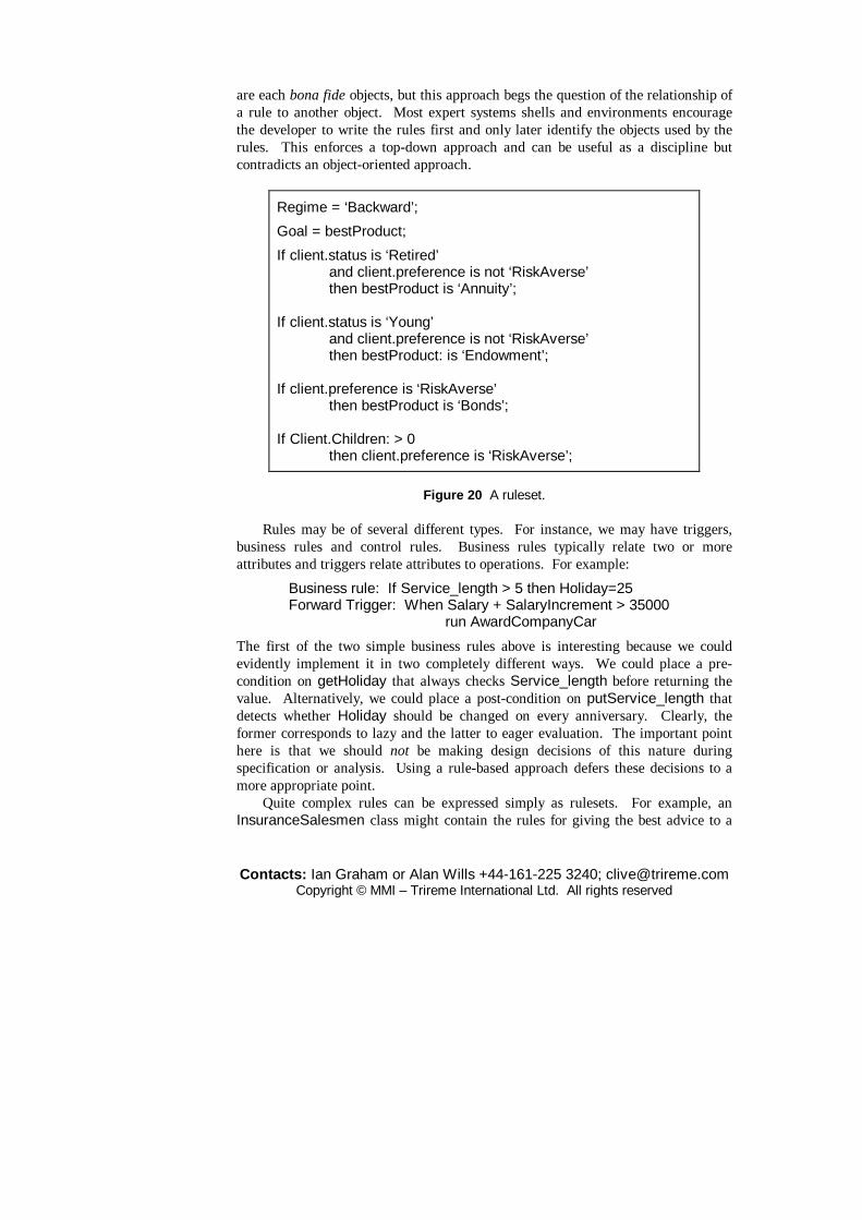
Contacts: Ian Graham or Alan Wills +44-161-225 3240; [email protected] Copyright © MMI – Trireme International Ltd. All rights reserved
are each bona fide objects, but this approach begs the question of the relationship of a rule to another object. Most expert systems shells and environments encourage the developer to write the rules first and only later identify the objects used by the rules. This enforces a top-down approach and can be useful as a discipline but contradicts an object-oriented approach.
Regime = ‘Backward’;
Goal = bestProduct;
If client.status is ‘Retired’ and client.preference is not ‘RiskAverse’ then bestProduct is ‘Annuity’; If client.status is ‘Young’ and client.preference is not ‘RiskAverse’ then bestProduct: is ‘Endowment’; If client.preference is ‘RiskAverse’ then bestProduct is ‘Bonds’; If Client.Children: > 0 then client.preference is ‘RiskAverse’;
Figure 20 A ruleset. Rules may be of several different types. For instance, we may have triggers,
business rules and control rules. Business rules typically relate two or more attributes and triggers relate attributes to operations. For example:
Business rule: If Service_length > 5 then Holiday=25 Forward Trigger: When Salary + SalaryIncrement > 35000 run AwardCompanyCar
The first of the two simple business rules above is interesting because we could evidently implement it in two completely different ways. We could place a pre-condition on getHoliday that always checks Service_length before returning the value. Alternatively, we could place a post-condition on putService_length that detects whether Holiday should be changed on every anniversary. Clearly, the former corresponds to lazy and the latter to eager evaluation. The important point here is that we should not be making design decisions of this nature during specification or analysis. Using a rule-based approach defers these decisions to a more appropriate point.
Quite complex rules can be expressed simply as rulesets. For example, an InsuranceSalesmen class might contain the rules for giving the best advice to a

Contacts: Ian Graham or Alan Wills +44-161-225 3240; [email protected] Copyright © MMI – Trireme International Ltd. All rights reserved
customer in the form shown in Figure 20. The rules fire when a value for BestProduct is needed. Note that these rules do not compromise the encapsulation of Client by setting the value of RiskAverse in that object. The salesman is merely making an assumption in the face of missing data or prompting the Client for that information. If the Client.preference attribute is already set to RiskAverse, these rules never fire. Note also the non-procedural character of this ruleset. The rule that fires first is written last. The ruleset executes under a backward chaining régime to seek a value for BestProduct. Thus, we can see that the language is non-procedural. That is, the ordering of a set of rules does not affect their interpretation.
UML and rules
UML’s qualifiers may be expressed as rules. For example, consider the many-to-many association between DOS files and directories. The Filename qualifier reduces this to a many-to-one association as illustrated in Figure 21. In general, qualification only partitions the sets. This is because qualification is relative; there is a degree of qualification. To avoid confusion we use rules such as ‘Every file in the ListOfFiles attribute must have a unique name’, a rule encapsulated in Directory. If FileNames is an attribute this can be avoided by writing FileNames[set of names] as opposed to [bag of ...] or [list of ...].
FileDirectory file name0..*
Figure 21 Qualified association.
In UML we can write invariants and rulesets in an (optional) fourth named compartment underneath the operations compartment of a type icon.
Rule-based extensions to object-oriented analysis help enrich the semantics of models of conventional commercial systems. This makes these models more readable and more reversible; more of the analysts’ intentions are evident in the model. This provides a truly object-oriented approach to the specification of advanced database and knowledge-based systems.
As we have seen, control rules are not the only rules in an application. We have mentioned business rules already. In both cases, encapsulating these rules in objects makes sense and enhances reusability and extensibility. System-wide rules belong in the most general objects in the system; i.e. the top of the hierarchy (or hierarchies if there is no catch-all class as there is with Smalltalk’s ‘object’). They are propagated to other parts of the system via inheritance. All kinds of rule are stored in the rulesets of the optional fourth window of the object icon.
Some researchers have applied this kind of rule-based idea to program

Contacts: Ian Graham or Alan Wills +44-161-225 3240; [email protected] Copyright © MMI – Trireme International Ltd. All rights reserved
browsers. These researchers believe that developers know much about their code that cannot be expressed formally which leads to time being wasted searching for implicit relationships. They suggest that the code should be related to a descriptive level that can be searched and manipulated. For example, the CogBrow research system supports operations such as: ‘Find all the routines written last week by J. Smith and change every occurrence of GOTO 32767 to GOTO END:’. Similarly assertions and rules can be manipulated as if they were at the descriptive level. There have also been attempts to apply objects with rules to object-oriented network modelling (Bapat, 1994).
It may be enlightening to know that we were first motivated to add rules to the Coad/Yourdon method in 1989 when using it, not to describe a computer system, but to build a model of an organization. This kind of activity, known these days as enterprise modelling or business process re-engineering, brings to the fore the need to record business rules, often expressed at a high level or vaguely – just the sort of thing knowledge-based systems builders are used to.
3.4 Invariants and encapsulation
We have seen already that cyclic associations imply invariants and that bi-directional associations violate the principle of encapsulation and are therefore incompatible with object-orientation. The object-oriented principle of encapsulation implies that bi-directional associations must be abandoned in object-oriented modelling, in favour of either uni-directional pointers or conversion to bona fide classes.
In our formalism as we have seen, objects encapsulate rulesets, along with the usual attributes and methods. To maintain the principle of encapsulation, objects must have rulesets; they are not an optional extra.
Most of the popular first-generation methods for object-oriented analysis (e.g. Coad and Yourdon, 1991; Rumbaugh et al., 1991; Shlaer and Mellor, 1988) and several of the less widely used ones offered a construct that placed a link between object types depicting static connexions other than generalization and composition. This construct is generally called an association. Some authors use the term ‘relationship’ as its synonym; whilst yet others use ‘relationship’ as a higher level abstraction which groups together association, usage, aggregation, collection, various flavours of inheritance, etc. Such associations describe one aspect of the connectivity between object types. This approach is familiar to most developers who have used entity-relationship techniques and is semantically identical since these associations refer only to the data structures of the objects and not to their behaviour (except in those rare instances where associations are used to denote messaging; e.g. object-oriented SSADM (Robinson and Berrisford, 1994)).
A study of the literature of semantic data modelling reveals that there are two

Contacts: Ian Graham or Alan Wills +44-161-225 3240; [email protected] Copyright © MMI – Trireme International Ltd. All rights reserved
fundamental ways to connect data structures or entity types: constructors and pointers. Delobel et al. (1995) explain that in the first approach, emphasis is placed on building structures using constructors such as the tuple or the set. In the second, the stress is on linking types using attributes. In the 1980s the former approach was dominant, largely because of the popularity and widespread use of relational databases. In entity-relationship models there are two logical types: entity-relationships and relationship-relationships. Both are represented by sets of tuples and no links between them are stored; the run-time system of the DBMS must search for the linkages. Attempts to enrich the relational model led quickly to systems with more than two relationship types. This unsatisfactory situation soon led to suggestions to replace these arbitrary type systems with a single notion of classes reminiscent of object-oriented programming. The pointer-based approach is far more natural to an OO thinker but one suspects that the popularity of methods such as OMT was due largely to the fact that developers with a relational background found its approach familiar and anodyne. The danger here is that object-oriented principles will be ignored and highly relational models produced instead of truly object-oriented ones. ASSOCIATIONS as types
We think that associations should point in one direction only because to do otherwise would violate the principle of encapsulation. Several object-oriented methodologists have argued against our position, saying that you can always add link attributes to an association and create from it an association object type. However, this new object type must retain links to its progenitors. Therefore, if we accept this as a solution, these new relationships must in turn give rise to new association object types. At some point we must stop this process and will still have to represent the residual associations connecting our, now more numerous, set of classes. This is not to deny the utility of association object types. Some associations are so important that they are themselves concepts; i.e. object types. An often quoted example is the marriage relationship between people, discussed below.
Of course, in any particular case, one can find a natural place to stop this process. It is usual to create types out of associations only when the association has interesting properties in its own right. This still leaves us with associations between the newly constructed types and the types that were previously linked by the original associations. Thus, in all practical cases, we will have failed to convert all associations to types although we will typically have removed all the many-to-many associations through this process. It is worth noting that while relational databases forbid the use of many-to-many relationships, they are not precluded by modern object-oriented databases. Thus the habit of always removing them, common among traditionally educated database designers, is no longer necessarily a good one.

Contacts: Ian Graham or Alan Wills +44-161-225 3240; [email protected] Copyright © MMI – Trireme International Ltd. All rights reserved
3.5 State models
For objects with significant complex state it is useful to use UML state charts or state transition diagrams (STDs). These diagrams are used to capture the dynamics of individual objects and are related to the object model as effective specification of operations and their assertions. Statecharts represent possible sequences of state change from a particular point of view. Each transition is a realization of an action or use case. Depending on the domain. it is recommended that the technique is used sparingly during specification as we believe it will not always be of use for many objects that occur in MIS systems and that its prime benefits arise during physical design. On the other hand, the technique is a familiar, useful and possibly anodyne one for many workers in Telecommunications.
Another problem with over-zealous use of STDs is that they can be very complex very quickly. However, for some objects with complex life histories the technique is invaluable for capturing information about both the business and the system. A good example of an object where the technique is suitable is a loan application. However, the very act of representing this business process as a class is highly questionable in itself. It is often better to capture this kind of information in a use case model which then refers to classes such as loans. The individual circumstances will dictate the best approach.
StateAdo: activityN
StateDdo: activityP
(attrib1:Type,attrib2:Type)[guard]/action1;action2;...event
Figure 22 States and transitions. An object’s significant states are determined by key arrangements of its
attribute values. These and the valid transitions between them are captured by a state transition diagram. Figure 22 illustrates the basic notation. States, which can be regarded as Boolean attributes of the type or values of a particular ‘state attribute’, are represented by rounded rectangles labelled with their names. Transitions are labelled arrows connecting states.

Contacts: Ian Graham or Alan Wills +44-161-225 3240; [email protected] Copyright © MMI – Trireme International Ltd. All rights reserved
Normal Menuvisible
Mousedown(right)/display popup
Mouseup(right)/hide popup
Mouseover/HighlightMenuItem
Start
Selected
Figure 23 An example.
nested states
superstate
substate1
substate2
event1
event3
event2
event1
concurrent states
superstate
substate1
substate2
substate3
substate4
event2
substate2 substate4
substate3substate1 event1
event2
event0event3
event4
process
Figure 24 STD notation. Events that cause transitions to occur are written next to the arrows. Events
may have attributes. For example, thinking of a calculator object, the event of pressing a key may have the attribute key_number. This avoids the need to have a separate event for each key. Events may have guards or pre-conditions. A guard determines a logical condition that must be true before the transition can take place. An action is a function that is executed – effectively instantaneously – after the transition occurs. States may have activities. These are functions that begin execution as soon as the state is entered and continue executing until completion or until the state is left, whichever is the earlier. A guard may mandate that the state may not be left until an activity is completed.

Contacts: Ian Graham or Alan Wills +44-161-225 3240; [email protected] Copyright © MMI – Trireme International Ltd. All rights reserved
Henderson-Sellers (private communication) points out that novices often misuse and overuse activities. They effectively use their STDs as DFDs in this way. The use of activities is therefore not encouraged.
Figure 23 gives a simple example showing part of the life history of a pop-up menu. Initial and final states are shown as filled circles and ringed filled circles respectively as shown in this example. Start and End (Selected here) are not states but represent the creation and destruction of instances, so that the attributes become undefined.
States may be nested and partitioned into concurrent states to make the structure neater. Figure 24 summarizes most of the rest of the notation. We have omitted some details such as start and end states to avoid clutter that would add little in the way of understanding the basic ideas.
Subtypes inherit the state models of their supertypes as illustrated in Figure 25, where the context is a simple graphical editor.
Shape
unselected selectedclick near this
click elsewhere
Polygon
selected
box-selected reshape-selected
right-click
reshaping:handles on
every corner
box-selected:move, stretch, etc.
more detail in one of the superclass’s states
Figure 25 States and subtypes. Sometimes it is useful to represent the states of a type as bona fide types; so that
rather than considering people as employed or unemployed we could create types for employees and so on. These can be considered as rôles, as discussed earlier, or as stative types. The latter view is useful when the attributes and behaviour are very different.
State charts, along with sequence diagrams, are useful for exploring and documenting use case refinements and making explicit the way a particular business process is implemented.

Contacts: Ian Graham or Alan Wills +44-161-225 3240; [email protected] Copyright © MMI – Trireme International Ltd. All rights reserved
STDs describe the local dynamics of each object in the system. We still need some techniques to describe global behaviour. However, the use of rulesets helps to encapsulate locally some aspects of global behaviour, as we have seen. Statecharts provide an additional way to visualize the problem and usually expose use cases that one has missed on the first pass. It is therefore important to cross-reference them against use cases. They make clear which action sequences are permissible.
3.6 Moving to component design
As we refine our specification into the design of a system and the set of components that constitute that system, we need to add more detail to any state, sequence and collaboration diagrams we have produced – focusing on the use cases at the system boundary. Typically, we will add timing constraints, guards, inter-object dependencies (such as «uses») and specify whether messages are sequential or asynchronous, and if the former, balking or subject to timeout.
RoomGuestoccupies
Hotel
* *occupant
HotelAdminSystem
0,1
0,1
use-caseHotelAdminSys::check_in (guest:Guest, inn1:Hotel)post guest.occupies.hotel = inn1
– guest occupies a Room in the requiredhotel ...
and guest.occcupies.occupant@pre = null– which was unoccupied previously
Figure 26 A Catalysis specification = type model + effects of use cases. The types contained in the specification of Figure 26 represent a model rather
than a mandate for the implementer. Any design is acceptable if it produces the behaviour implied by the use case specifications; the model supplies the vocabulary for expressing them. Only the use cases in the bottom section are required. Operations can be assigned to contained types but they are interpreted as ‘factored’ specifications. If we assign the operation reallocateRoom to Guest, this means that the system provides a facility with that name, one of whose parameters is
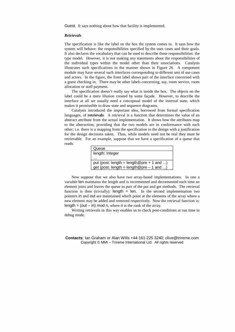
Contacts: Ian Graham or Alan Wills +44-161-225 3240; [email protected] Copyright © MMI – Trireme International Ltd. All rights reserved
Guest. It says nothing about how that facility is implemented. Retrievals
The specification is like the label on the box the system comes in. It says how the system will behave: the responsibilities specified by the uses cases and their goals. It also declares the vocabulary that can be used to describe these responsibilities: the type model. However, it is not making any statements about the responsibilities of the individual types within the model other than their associations. Catalysis illustrates such specifications in the manner shown in Figure 26. A component module may have several such interfaces corresponding to different sets of use cases and actors. In the figure, the front label shows part of the interface concerned with a guest checking in. There may be other labels concerning, say, room service, room allocation or staff payment.
The specification doesn’t really say what is inside the box. The objects on the label could be a mere illusion created by some façade. However, to describe the interface at all we usually need a conceptual model of the internal state, which makes it permissible to draw state and sequence diagrams.
Catalysis introduced the important idea, borrowed from formal specification languages, of retrievals. A retrieval is a function that determines the value of an abstract attribute from the actual implementation. It shows how the attributes map to the abstraction, providing that the two models are in conformance with each other; i.e. there is a mapping from the specification to the design with a justification for the design decisions taken. Thus, while models need not be real they must be retrievable. For an example, suppose that we have a specification of a queue that reads:
Queue length: Integer ... put (post: length = length@pre + 1 and ...) get (post: length = length@pre – 1 and ...)
Now suppose that we also have two array-based implementations. In one a
variable len maintains the length and is incremented and decremented each time an element joins and leaves the queue as part of the put and get methods. The retrieval function is then (trivially): length = len. In the second implementation two pointers in and out are maintained which point at the elements of the array where a new element may be added and removed respectively. Now the retrieval function is: length = (out – in) mod n, where n is the rank of the array.
Writing retrievals in this way enables us to check post-conditions at run time in debug mode.

Contacts: Ian Graham or Alan Wills +44-161-225 3240; [email protected] Copyright © MMI – Trireme International Ltd. All rights reserved
Packages, modules and wrappers
We will also usually organize our classes into discrete packages. Any modelling language with ambitions to describe non-trivial systems or systems of great magnitude must adopt some sort of packaging strategy to reduce the complexity of its models. Many other methods have a fairly informal approach, so that the unit of packaging is only loosely defined by some heuristic such as: keep closely related classes in the same package.
Figure 27 Dependency between packages. Packages are groups of related classes, associations and use cases. This kind of
packaging gives a way to organize large models, separate domains and enforce a cleaner architecture. A package can make use of items defined in other packages in which case there is a dependency; the package will not work on its own. Such usage dependencies between packages should preferably be non-circular to ensure that the model has a clear meaning and to allow anyone who imports one package not to have to import all the others. Figure 27 shows the UML notation for packages and indicates the goodness or badness of different architectures using it. Dependency relationships between packages can be drawn automatically by most tools and packages can usually be exported and imported between models. The most obvious correspondence between the UML package notation and the features of a language is the notion of a package in Java. Catalysis model templates are

Contacts: Ian Graham or Alan Wills +44-161-225 3240; [email protected] Copyright © MMI – Trireme International Ltd. All rights reserved
parametrized packages. UML module or component diagrams use the ‘Gradygrams’ shown in Figure
28. Components can be assigned to ‘nodes’: physical computers. Nodes are displayed as cuboids like the one in Figure 26. Components with several interfaces show each one as a ‘lollipop’.
X Y
A
B
C
D
E
Figure 28 Wrappers and delegation. It is sometimes useful to have a stronger notion of what constitutes a package.
We feel the need for a more rigorously defined notion based on the idea that the packages encapsulate (i.e. hide) their contents. Originally this concept was called a layer in SOMA, but it is now clear that this word should be reserved for the idea of client-server or architectural layers connected via API ports, as found in the OSI seven-layer model or the layers of the ROOM method (Selic et al., 1994). Therefore, we now call these encapsulating packaging units wrappers. Wrappers encapsulate their components. No new notation is needed for wrappers because a wrapper is merely a composite object and we can fall back on the standard UML composition notation. Since wrappers are components and component specifications are types we can use the UML type or component symbols for them. We may also overload the term wrapper to mean also an object encapsulating a conventional legacy system. This does no violence to our language because, after all, a plain vanilla object is nothing other than a simple conventional system consisting of functions and data.
Wrappers delegate some or all of the responsibilities in their interfaces to the operations of their components. These delegations are referred to as implemented-

Contacts: Ian Graham or Alan Wills +44-161-225 3240; [email protected] Copyright © MMI – Trireme International Ltd. All rights reserved
by links. They are as yet unsupported directly in UML but, pending this, one may readily annotate an operation with the syntax:
/* Implemented-by Classname.operation_name */
This notion corresponds to the idea that wrapper operations delegate some or all of their responsibilities to the operations of their components. Notationally, layers might also be shown using a Gradygram notation as in Figure 35, which is sometimes preferable since it is easier to show implemented-by links in this way. Note that inbound messages cannot penetrate a wrapper but outbound ones can.
Wrappers encapsulate business functions and facilitate the use of existing components that are not necessarily object-oriented. A typical application is the application layer of a normal three-tier architecture.
A viable alternative to the informal notation we have used here is OML’s cluster notation (Firesmith et al., 1997), which we do not present here because it would take us too far from our main theme. One can also use UML’s package notation. For an interesting comparison of the two notations in the context of wrappers see O’Callaghan (1997a). Templates or model frameworks
Objects interact through contracts with other objects and these interactions define rôles for the objects. When an object plays several rôles its state is affected by all of them. For example, if someone is an employee and a parent then one rôle replenishes the bank account drained by the other. From this point of view the collaborations are just as much reusable chunks as are the objects themselves.
Collaborations have always been a key focus in object-oriented design. Distributing the responsibilities among objects is the key to successful decoupling. In fact most design patterns describe the relationships among a set of several objects, focusing on particular rôles; e.g. SUBJECT-OBSERVER (Gamma et al., 1995). Catalysis introduced a way of modelling such patterns of collaboration with the idea of a model framework or template (Wills, 1996). ‘Model framework’ and ‘model template’ are synonyms and correspond to the UML 1.3 idea of a ‘Collaboration’ – not to be confused with the UML ‘collaboration’ (cf. Fowler, 1997, p.116).
A model framework is a related group of packages for the developer to build upon. It only makes sense when you can substitute fairly concrete things for its abstract concepts. Catalysis shows how to do this with the notion of substitutable placeholders. Typically, a framework represents a reusable pattern.
In Figure 29, we assume that we have completed first a model of the plumbing domain and later realized that we can abstract away from the detail of plumbing and consider the more general problem of resource allocation to conform to the same pattern. We therefore create a ‘macro’ version of the model. The terms that will vary from domain to domain are replaced with abstract placeholders. When the template is realized the placeholders are replaced by ‘real’ types according to the
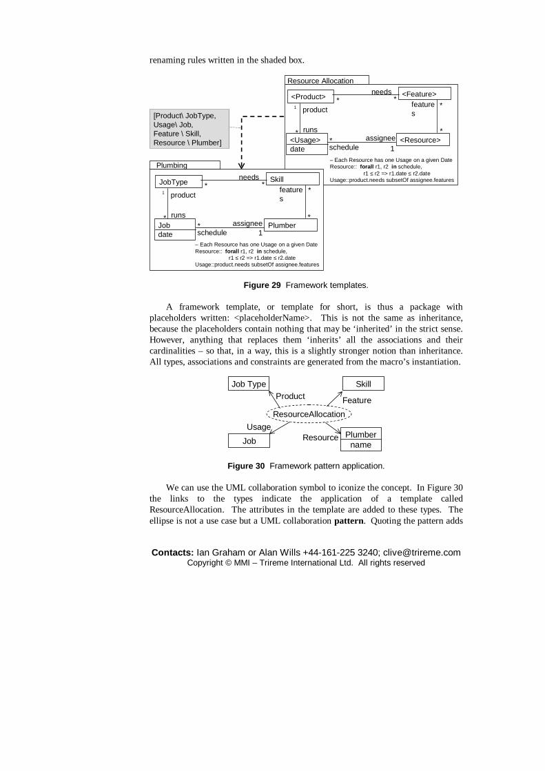
Contacts: Ian Graham or Alan Wills +44-161-225 3240; [email protected] Copyright © MMI – Trireme International Ltd. All rights reserved
renaming rules written in the shaded box.
<Usage>date
<Resource>
<Product>
1*
*
Resource Allocation
– Each Resource has one Usage on a given DateResource:: forall r1, r2 in schedule,
r1 ≤ r2 => r1.date ≤ r2.dateUsage::product.needs subsetOf assignee.features
1 product**
[Product\ JobType,Usage\ Job,Feature \ Skill,Resource \ Plumber]
Plumbing
<Feature>
runs
scheduleassignee
needs
*
*
features
Jobdate
Plumber
JobType
1*
*
1 product**
Skill
runs
scheduleassignee
needs
*
*
features
– Each Resource has one Usage on a given DateResource:: forall r1, r2 in schedule,
r1 ≤ r2 => r1.date ≤ r2.dateUsage::product.needs subsetOf assignee.features
Figure 29 Framework templates. A framework template, or template for short, is thus a package with
placeholders written: <placeholderName>. This is not the same as inheritance, because the placeholders contain nothing that may be ‘inherited’ in the strict sense. However, anything that replaces them ‘inherits’ all the associations and their cardinalities – so that, in a way, this is a slightly stronger notion than inheritance. All types, associations and constraints are generated from the macro’s instantiation.
Job Type
Job
Skill
Plumbername
ResourceAllocation
Product
UsageResource
Feature
Figure 30 Framework pattern application. We can use the UML collaboration symbol to iconize the concept. In Figure 30
the links to the types indicate the application of a template called ResourceAllocation. The attributes in the template are added to these types. The ellipse is not a use case but a UML collaboration pattern. Quoting the pattern adds

Contacts: Ian Graham or Alan Wills +44-161-225 3240; [email protected] Copyright © MMI – Trireme International Ltd. All rights reserved
macro-instantiated features to existing types.
Course
CourseRunInstructor
Instructor SkillRoom Facility
Room
ResourceAllocation
Product
UsageResource
FeatureResourceAllocation
Product
UsageResource
Feature
Figure 31 Multiple pattern application. We can apply the pattern more than once in the same application. Figure 31
shows how it might be applied twice in the context of teaching administration. The resource placeholder maps to Instructor in one case and to Room in the other. In this example we need to amend the type model, not only by making explicit type substitutions but by disambiguating associations by renaming them, as shown in Figure 32. We also need to specialize any ambiguous invariants. Thus, the invariant displayed in Figure 29 becomes:
– Each Instructor has one CourseRun on a given Date Instructor:: forall r1, r2 in schedule, r1 ? r2 => r1.date ? r2.date CourseRun:: product.needsInstructorSkills subsetOf assigneeInstructor.features
for Instructor and has different terms for Room.
CourseRundate
Course
*
*
1 product *
runsschedule
Instructor1
*Instructor Skill
assignedInstructor
needsInstructorSkills
*
*
features
Room1
*Room Facility
needsRoomFacilities
*
*
features
*
*schedule
assignedRoom
Figure 32 Unfolded type model for pattern application. Frameworks may include use cases and their post-conditions as well as types
and associations. These can be shown either graphically (as ellipses) or textually. This helps greatly with component design. Even the simple Sale use case that we
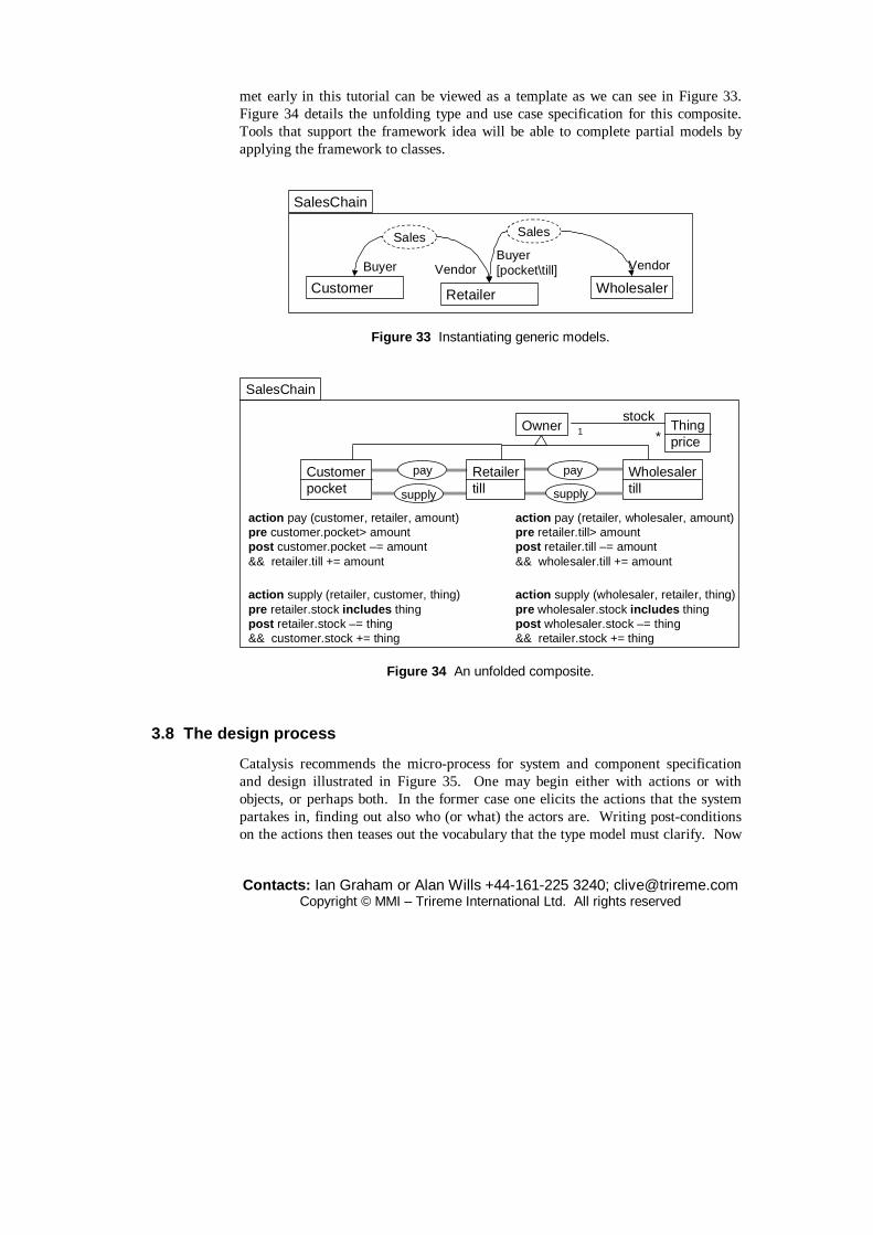
Contacts: Ian Graham or Alan Wills +44-161-225 3240; [email protected] Copyright © MMI – Trireme International Ltd. All rights reserved
met early in this tutorial can be viewed as a template as we can see in Figure 33. Figure 34 details the unfolding type and use case specification for this composite. Tools that support the framework idea will be able to complete partial models by applying the framework to classes.
Buyer[pocket\till] Vendor
Retailer WholesalerVendor
Customer
SalesChain
Sales Sales
Buyer
Figure 33 Instantiating generic models.
SalesChain
Customerpocket
Wholesalertill
action pay (retailer, wholesaler, amount)pre retailer.till> amountpost retailer.till –= amount&& wholesaler.till += amount
Thingprice
Ownerstock
1 *
action supply (wholesaler, retailer, thing)pre wholesaler.stock includes thingpost wholesaler.stock –= thing&& retailer.stock += thing
action pay (customer, retailer, amount)pre customer.pocket> amountpost customer.pocket –= amount&& retailer.till += amount
action supply (retailer, customer, thing)pre retailer.stock includes thingpost retailer.stock –= thing&& customer.stock += thing
pay
supplysupply
pay Retailertill
Figure 34 An unfolded composite.
3.8 The design process
Catalysis recommends the micro-process for system and component specification and design illustrated in Figure 35. One may begin either with actions or with objects, or perhaps both. In the former case one elicits the actions that the system partakes in, finding out also who (or what) the actors are. Writing post-conditions on the actions then teases out the vocabulary that the type model must clarify. Now

Contacts: Ian Graham or Alan Wills +44-161-225 3240; [email protected] Copyright © MMI – Trireme International Ltd. All rights reserved
the techniques of snapshot, sequence and state diagrams are used to clarify and refine the model, leading to new and additional actions. And so on round the loop, introducing more detail and eventually moving from a specification to a design and implementation.
what else do they do/ happens to them?– draw statecharts, sequence diagrams
Objects, attributes &associations
Book
Member
onLoanTo 0..1
*
what happens?– tasks, jobs, use cases
action borrow(member, library, book)post book is on loan to member
what objects are there?– things, concepts, relationships
borrow
Member
LibraryBook
Actions,operations
who/whatis affected?– write post-conditions, look at terms used
Figure 35 The Catalysis specification and design micro-process.
The important design principles that should be applied during the process are as follows.
� Assign responsibilities to objects evenly, trying to get objects of roughly similar size.
� Ensure that all associations are directional. � Clarify invariants by using snapshots. � Avoid circularity and high fanouts (as already shown in Figure 34). � Make sure that dependencies are layered. � Minimize coupling and visibility between objects. � Apply patterns throughout the design process. � Iterate until model is stable or deadline approaches.

Contacts: Ian Graham or Alan Wills +44-161-225 3240; [email protected] Copyright © MMI – Trireme International Ltd. All rights reserved
3.9 Documenting models
One of the great dangers that comes for free when you buy an OO CASE tool is the temptation to produce huge class diagrams documenting every class in a system, along with masses of supplementary pictures. The tools make this easy to do. Such work products will be completely useless a few weeks after they are produced and probably not readable by anyone but the developer who produced them.
Each Room can be occupied by atmost one Guest. (The occupant is theperson responsible for payment. Theremay be others staying in the room, butwe are not interested in them.)
The room may be clean or unclean; anoccupied room is always consideredunclean.
Guest Roomoccupant0..1
Roomclean : bool
(occupant != null) => !clean
Each Room is assigned one Cleaner.
The Cleaner may have several Rooms.
Room Cleanercleaner
0..* 1
Figure 36 Documentation style. Small diagrams are sometimes useful for illustrating narrative documentation,
but remember: only developers speak UML. Don’t expect users to be able to interpret them – at least not without help. The text must therefore explicate the information summarized in the diagram. Figure 36 illustrates the style of documentation that we favour. There will also be state and sequence diagrams where these illuminate the text.
A project glossary or dictionary is usually an important component of the documentation. It defines the types and all attributes, operations and invariants associated with them. It could also include coverage of business concepts that are relevant to the domain but which do not show up in the type model. Classes should be assigned keywords to help with finding them automatically. A good syntax for this is: topic = Biology; owner = Smith; etc.
Strictly speaking, all the diagrams are redundant because they could all be generated automatically from the type descriptions (Graham, 1998). However, illustration can be helpful to some readers and help with the precision of one’s thinking.

Contacts: Ian Graham or Alan Wills +44-161-225 3240; [email protected] Copyright © MMI – Trireme International Ltd. All rights reserved
3.10 Real-time extensions
Applets running in browsers and many real-time applications bring issues of concurrency to the fore. This kind of program can (or can appear to) do several things at once. A thread represents a concurrent sequence of steps and there may be many of these that can start, stop and signal to each other. A simple and familiar example is a GIF image being downloaded to a browser while the user continues to be able to click on hyperlinks. Threads are a key part of the Java object model. Buhr and Casselman (1996) describe Ray Buhr’s important and powerful technique of time threads. Time threads (re-badged – we think rather opportunistically – in the cited book as ‘use case maps’) enable designers to visualize the way a system transfers control amongst its components. In this sense a thread is rather like the internalization of a use case. However, these authors routinely confuse use cases with scenarios and most examples that they give deal with using time threads to model scenarios rather than, more generically, use cases. A time thread map shows the components of a system (which could be machines or people) and one or more wiggly lines that pass through the components and which are annotated with (possibly shared) responsibilities. Components can be objects or pure processes. Time threads can branch and join. They can be synchronized according to a number of protocols. In fact, one can make an exhaustive list of the different patterns of inter-process coupling that can occur. Threads can access ‘pools’ of information and populate object ‘slots’ dynamically.
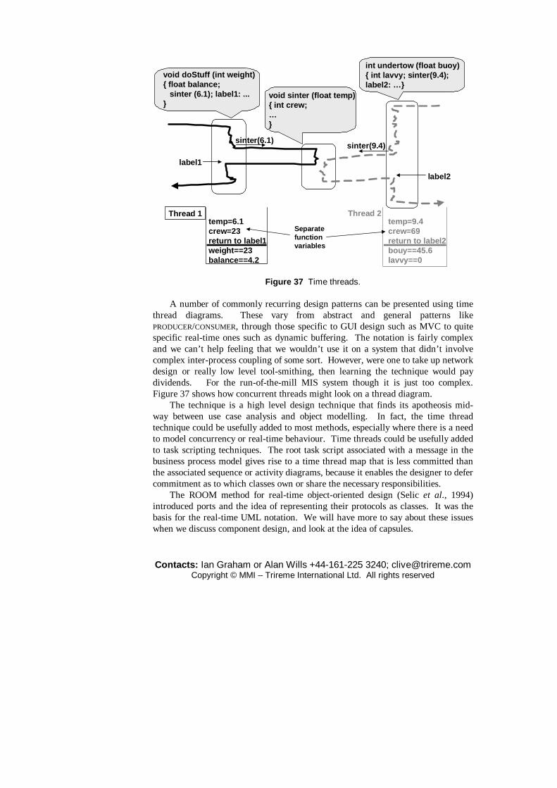
Contacts: Ian Graham or Alan Wills +44-161-225 3240; [email protected] Copyright © MMI – Trireme International Ltd. All rights reserved
void doStuff (int weight){ float balance; sinter (6.1); label1: ...}
void sinter (float temp){ int crew;…}
int undertow (float buoy){ int lavvy; sinter(9.4);label2: …}
label1
label2
Thread 2temp=9.4crew=69return to label2bouy==45.6lavvy==0
Thread 1temp=6.1crew=23return to label1weight==23balance==4.2
sinter(6.1)sinter(9.4)
Separate functionvariables
Figure 37 Time threads.
A number of commonly recurring design patterns can be presented using time thread diagrams. These vary from abstract and general patterns like PRODUCER/CONSUMER, through those specific to GUI design such as MVC to quite specific real-time ones such as dynamic buffering. The notation is fairly complex and we can’t help feeling that we wouldn’t use it on a system that didn’t involve complex inter-process coupling of some sort. However, were one to take up network design or really low level tool-smithing, then learning the technique would pay dividends. For the run-of-the-mill MIS system though it is just too complex. Figure 37 shows how concurrent threads might look on a thread diagram.
The technique is a high level design technique that finds its apotheosis mid-way between use case analysis and object modelling. In fact, the time thread technique could be usefully added to most methods, especially where there is a need to model concurrency or real-time behaviour. Time threads could be usefully added to task scripting techniques. The root task script associated with a message in the business process model gives rise to a time thread map that is less committed than the associated sequence or activity diagrams, because it enables the designer to defer commitment as to which classes own or share the necessary responsibilities.
The ROOM method for real-time object-oriented design (Selic et al., 1994) introduced ports and the idea of representing their protocols as classes. It was the basis for the real-time UML notation. We will have more to say about these issues when we discuss component design, and look at the idea of capsules.

Contacts: Ian Graham or Alan Wills +44-161-225 3240; [email protected] Copyright © MMI – Trireme International Ltd. All rights reserved
4 Identifying objects
Now, and only now that we have the intellectual tools necessary to describe and model objects, we can start to think about how to discover and invent them. We have seen that spotting the nouns and verbs in the post-conditions of use cases is a very useful technique for establishing the vocabulary of the domain and thereby the static type model. However, detailed discussion of how to go about identifying objects has been deferred until now, because we could not have described what we would have been looking for had we dealt with this earlier. The second reason for this is that object identification is recognized as a key, possibly the key, bottleneck in applying both object-oriented design and analysis. In this respect the topic deserves the attention of a separate section, in which we will try to show that the object identification bottleneck is as chimerical as the famous Feigenbaum knowledge acquisition bottleneck. Techniques exist to help apprehend objects, mostly those in use already in data modelling and knowledge engineering, and good analysts do not, in practice, stumble badly in this area. Textual analysis
Booch’s original object-oriented design method began with a dataflow analysis which was then used to help identify objects by looking for both concrete and abstract objects in the problem space found from the bubbles and data stores in a data flow diagram (DFD). Next, methods are obtained from the process bubbles of the DFD. An alternative but complementary approach, first suggested by Abbott (1983), is to extract the objects and methods from a textual description of the problem. Objects correspond to nouns and methods to verbs. Verbs and nouns can be further subclassified. For example, there are proper and improper nouns, and verbs to do with doing, being and having. Doing verbs usually give rise to methods, being verbs to classification structures and having verbs to composition structures. Transitive verbs generally correspond to methods, but intransitive ones may refer to exceptions or time-dependent events; in a phrase such as ‘the shop closes’, for example. This process is a helpful guide but may not be regarded as any sort of formal method. Intuition is still required to get hold of the best design. This technique can be automated as some of the tools developed to support HOOD and Saeki et al. (1989) showed.
For example, a requirements statement transcript might contain the following fragment:
... If a customer enters a store with the intention of buying a toy for a child, then advice must be available within a reasonable time concerning the

Contacts: Ian Graham or Alan Wills +44-161-225 3240; [email protected] Copyright © MMI – Trireme International Ltd. All rights reserved
suitability of the toy for the child. This will depend on the age range of the child and the attributes of the toy. If the toy is a dangerous item, then it is unsuitable. ...
We have emboldened some candidate classes (nouns) and italicized some candidate methods (transitive verbs). Possible attributes or associations are underlined. The process could be continued using the guidelines set out in Table 1, but it must be understood that this is not a formal technique in any sense of the word. The table is intended merely to provoke thought during analysis.
Most of the methods descended from Booch’s work, including those based on UML, use some form of textual analysis of this sort.
HOOD, RDD and some other methods used Abbott textual analysis but otherwise there are no precise, normative techniques. Coad and Yourdon (1991) say that analysts should look for things or events remembered, devices, rôles, sites and organizational units. The Shlaer-Mellor method offers five categories: tangible entities, rôles, incidents, interactions and specifications. This is all very well, but rather fuzzy and certainly not complete. Coad et al. (1999) say that there are exactly five kinds of archetypal objects and gives standard features for each one. Each archetype is associated with a colour – based on the colours of commercially available pads of paper stickers. His archetypes are objects representing:
� descriptions (blue); � parties (e.g. people, organizations), places or things (green); � rôles (yellow); � moments in or intervals of time (pink); and � interfaces and plug-points.
It is difficult to be completely convinced that the world is really so simple, but the idea is a useful one and emphasizes the recurrence of analysis patterns. This section provides several, quite precise, normative techniques for eliciting objects. They are founded in knowledge engineering, HCI practice and philosophy.
Table 1 Guidelines for textual analysis. Part of speech Model component Example from SACIS text proper noun instance J. Smith improper noun class/type/rôle toy doing verb operation buy being verb classification is an having verb composition has an stative verb invariance-condition are owned modal verb data semantics, pre-condition,
post-condition or invariance-condition
must be
adjective attribute value or class unsuitable

Contacts: Ian Graham or Alan Wills +44-161-225 3240; [email protected] Copyright © MMI – Trireme International Ltd. All rights reserved
adjectival phrase association operation
the customer with children the customer who bought the kite
transitive verb operation enter intransitive verb exception or event depend
As we have suggested, most object-oriented analysis methods give little help on the process of identifying objects. It is a very reasonable approach to engage in the analysis of nouns, verbs and other parts of speech in an informal written description of the problem or a set of use case post-conditions. Rules of thumb here include: matching proper nouns to instances, and improper nouns to types or attributes; adjectival phrases qualifying nouns such as ‘the employee who works in the salaries department’ indicate relations or may indicate methods if they contain verbs as in ‘the employee who got a rise’.
The Abbott technique is useful, but cannot succeed on its own. This semi-structured approach is only a guide and creative perception must be brought to bear by experienced analysts, as we have already emphasized. Using it involves difficult decisions.
Essential & accidental judgments
Fred Brooks (1986) notes the difference between essence and accidents in software engineering. The distinction is, in fact, a very old one going back to Aristotle and the mediaeval Scholastics. The idea of essence was attacked by modern philosophers from Descartes onwards, who saw objects as mere bundles of properties with no essence. This gave rise to severe difficulties because it fails to explain how we can recognize a chair with no properties in common with all the previous chairs we have experienced. A school of thought known as Phenomenology, represented by philosophers such as Hegel, Brentano, Husserl and Heidegger, arose inter alia from attempts to solve this kind of problem. Another classical problem, important for object-oriented analysis, is the problem of categories. Aristotle laid down a set of fixed pairs of categories through the application of which thought could proceed. These were concepts such as Universal/Individual, Necessary/Contingent, and so on. Kant gave a revised list but, as Hegel once remarked, didn’t put himself to much trouble in the doing. The idealist Hegel showed that the categories were related and grew out of each other in thought. Finally, the materialist Marx showed that the categories of thought arose out of human social and historical practice:
My dialectic method is not only different from the Hegelian, but is its direct opposite. To Hegel, the life-process of the human brain, i.e. the process of thinking, which, under the name of ‘the Idea’, he even transforms into an independent subject, is the demiurgos of the real world, and the real world is

Contacts: Ian Graham or Alan Wills +44-161-225 3240; [email protected] Copyright © MMI – Trireme International Ltd. All rights reserved
only the external, phenomenal form of ‘the Idea’. With me, on the contrary, the ideal is nothing else than the material world reflected by the human mind, and translated into forms of thought. (Marx, 1961)
So, we inherit categories from our forebears, but also learn new ones from our practice in the world.
All phenomenologists and dialecticians, whether idealist or materialist, acknowledge that the perception or apprehension of objects is an active process. Objects are defined by the purpose of the thinking subject, although for a materialist they correspond to previously existing patterns of energy in the world – including of course patterns in the brain. A chair is a coherent object for the purposes of sitting (or perhaps for bar-room brawling) but not for the purposes of sub-atomic physics. You may be wondering by now what all this has got to do with object-oriented analysis. What does this analysis tell us about the identification of objects? The answer is that it directs attention to the user.
User-centred analysis requires that we ask about purpose when we partition the world into objects. It also tells us that common purpose is required for reusability, because objects designed for one user may not correspond to anything in the world of another. In fact reuse is only possible because society and production determine a common basis for perception. A clear understanding of Ontology helps to avoid the introduction of accidental, as opposed to essential, objects. Thus, Fred Brooks, in our opinion, either learned some Ontology or had it by instinct alone.
Some useful tips for identifying important, rather than arbitrary, objects can be gleaned from a study of philosophy, especially Hegelian philosophy and modern Phenomenology. Stern (1990) analyses Hegel’s concept of the object in great detail. The main difference between this notion of objects and other notions is that objects are neither arbitrary ‘bundles’ of properties (the Empiricist or Kantian view), nor are they based on a mysterious essence, but are conceptual structures representing universal abstractions. The practical import of this view is that it allows us to distinguish between genuine high level abstractions such as Man and completely contingent ones such as Red Objects. Objects may be judged according to various, historically determined, categories. For example ‘this rose is red’ is a judgment in the category of quality. The important judgments for object-oriented analysis and their relevant uses are those shown in Table 2.
Table 2 Analysis of judgments.
Judgment Example Feature Quality this ball is red attribute Reflection this herb is medicinal relationship Categorical Fred is a man generalization Value Fred should be kind rules

Contacts: Ian Graham or Alan Wills +44-161-225 3240; [email protected] Copyright © MMI – Trireme International Ltd. All rights reserved
The categorical judgment is the one that reveals genuine high level abstractions. We call such abstractions essential. Qualitative judgments only reveal contingent and accidental properties unlikely to be reusable, but nevertheless of semantic importance within the application. Beware, for example, of abstractions such as ‘red roses’ or ‘dangerous toys’; they are qualitative and probably not reusable without internal restructuring. Objects revealed by qualitative judgments are called accidental. Accidental objects are mere bundles of arbitrary properties, such as ‘expensive, prickly, red roses wrapped in foil’. Essential objects are universal, in the sense that they are (or belong to) classes which correspond to objects that already have been identified by human practice and are stable in time and space. What they are depends on human purposes; prior to trade money was not an object. Reflective judgments are useful for establishing usage relationships and methods; being medicinal connects herbs to the sicknesses that they cure. Value judgments may be outside the scope of a computer system, but can reveal semantic rules. For example, we could have, at a very high business analysis level, ‘employees should be rewarded for loyalty’ which at a lower level would translate to the rule: ‘if five years’ service then an extra three days’ annual leave’.
Attributes are functions that take objects as values; that is, their ranges are classes. They may be distinguished into attributes whose values are abstract (or essential in the sense alluded to above) objects like employee, and those with printable, i.e. accidental, objects as values like redness. This observation has also been made in the context of semantic data models by Hull and King (1987).
For business and user-centred design, the ontological view dictates that objects should have a purpose. Operations too should have a goal. In several methods this is accomplished by specifying post-conditions. These conditions should be stated for each method (as in Eiffel) and for the object as a whole in the rules compartment of an object.
Lenat and Guha (1990) suggest that instances are things that something definite can be said about, but point out the danger of relying too much on the structure of natural language. They suggest that a concept should be abstracted as a class if:
� several interesting things can be said about it as a whole; � it has properties shared by no other class; � there are statements that distinguish this class from some larger class it
belongs to; � the boundaries of the concept are imprecise; � the number of ‘siblings’ (e.g. complementary classes whose union is the
natural generalization of this one) is low.
They also emphasize the point we have made: that purpose is the chief determinant of what is to be a class or type.
A useful rule of thumb for distinguishing essential objects is that one should ask if more can be said about the object than can be obtained by listing its attributes

Contacts: Ian Graham or Alan Wills +44-161-225 3240; [email protected] Copyright © MMI – Trireme International Ltd. All rights reserved
and methods. It is cheating in the use of this rule to merely keep on adding more properties. Examples abound of this type of object. In a payroll system, an employee may have red hair, even though this is not an attribute, or be able to fly a plane, even though this is not a method. Nothing special can be said about the class ‘employees who can fly’ unless, of course, we are dealing with the payroll for an airline. What is essential is context sensitive.
Very long methods, objects with hundreds of attributes and/or hundreds of methods indicate that you are trying to model something that normal mortals couldn’t apprehend in any conceivable perceptive act. This tells us, and we hope your project manager, that you haven’t listened to the users.
It is not only the purposes of the immediate users that concern us, but the purposes of the user community at large and, indeed, of software engineers who will reuse your objects. Therefore, analysts should keep reuse in mind throughout the requirements elicitation process. Designing or analysing is not copying user and expert knowledge. As with perception, it is a creative act. A designer, analyst or knowledge engineer takes the purposes and perceptions of users and transforms them. S/he is not a tabula rasa – a blank sheet upon which knowledge is writ – as older texts on knowledge elicitation used to recommend, but a creative participant.
Johnson and Foote (1988) make a few suggestions for desiderata concerning when to create a new class rather than add a method to an existing class which seem to conform to the ontological insights of this section.
Epistemology has been studied by knowledge engineers involved in building expert systems. Many of the lessons learnt and the techniques they have discovered can be used in building conventional systems, and this is now routine in our work. In particular, they can be applied to HCI design (Johnson, 1992) and within object-oriented analysis and design.
4.2 Task analysis
Several of the methods which have been developed by knowledge engineers trying to elicit knowledge from human beings with the aim of building expert systems can be used to obtain concepts in any domain. These concepts often map onto objects. This is not the place for an exegesis on methods of knowledge acquisition, but we should mention the usefulness of methods based on Kelly grids (or repertory grids), protocol analysis, task analysis and interviewing theory. The use of the techniques of Kelly grids for object identification is explained later in this section. Protocol analysis (Ericsson and Simon, 1984) is in some ways similar to the procedure outlined earlier of analysing parts of speech, and task analysis can reveal both objects and their methods. Task analysis is often used in UI design (Daniels, 1986; Johnson, 1992).
Broadly, task analysis is a functional approach to knowledge elicitation which involves breaking down a problem into a hierarchy of tasks that must be performed.
Contacts: Ian Graham or Alan Wills +44-161-225 3240; [email protected] Copyright © MMI – Trireme International Ltd. All rights reserved
The objectives of task analysis in general can be outlined as the definition of:
� the objectives of the task; � the procedures used; � any actions and objects involved; � time taken to accomplish the task; � frequency of operations; � occurrence of errors; � involvement of subordinate and superordinate tasks.
The result is a task description which may be formalized in some way, such as by flowcharts, logic trees or even a formal grammar. The process does not, however, describe knowledge directly. That is, it does not attempt to capture the underlying knowledge structure but tries to represent how the task is performed and what is needed to achieve its aim. Any conceptual or procedural knowledge and any objects which are obtained are only elicited incidentally.
In task analysis the objective constraints on problem solving are exploited, usually prior to a later protocol analysis stage. The method consists in arriving at a classification of the factors involved in problem solving and the identification of the atomic ‘tasks’ involved. The categories that apply to an individual task might include:
� time taken; � how often performed; � procedures used; � actions used; � objects used; � error rate; � position in task hierarchy.
This implies that it is also necessary to identify the actions and types in a taxonomic manner. For example, if we were to embark on a study of poker playing we might start with the following crude structure:
Types: Card, Deck, Hand, Suit, Player, Table, Coin Actions: Deal, Turn, See, Collect
One form of task analysis assumes that concepts are derivable from pairing actions with types; e.g. ‘See player’, ‘Deal card’. Once the concepts can be identified it is necessary to identify plans or objectives (win game, make money) and strategies (bluff at random) and use this analysis to identify the knowledge required and used by matching object–action pairs to task descriptions occurring in task sequences. As mentioned before, this is important since objects are identified in relation to purposes.
As a means of breaking down the problem area into its constituent sub-problems, task analysis is useful in a similar way to data flow analysis or entity

Contacts: Ian Graham or Alan Wills +44-161-225 3240; [email protected] Copyright © MMI – Trireme International Ltd. All rights reserved
modelling. Although the method does incorporate the analysis of the objects associated with each task, it is lacking in graphical techniques for representation of these objects, and therefore remains mostly useful for functional elicitation.
The approach to cognitive task analysis recommended by Braune and Foshay (1983), based on human information processing theory, is less functional than the basic approach to task analysis as outlined above, concentrating on the analysis of concepts. The second stage of the three-step strategy is to define the relations between concepts by analysing examples, then to build on the resulting schema by analysing larger problem sets. The schema that results from the above analysis is a model of the knowledge structure of an expert, similar to that achieved by the concept sorting methods associated with Kelly grids, describing the ‘chunking’ of knowledge by the expert. This chunking is controlled by the idea of expectancy according to the theory of human information processing; i.e. the selection of the correct stimuli for solving the problem, and the knowledge of how to deal with these stimuli. As pointed out by Swaffield (1990), this approach is akin to the ideas of object modelling due to the concentration on the analysis of concepts and relations before further analysis of functions/tasks.
A task is a particular instance of a procedure that achieves a goal. There can be many tasks that achieve the same goal. Use cases are examples of tasks; they should always state their goal. We hope to be able to extract eventually a business object model from the tasks we have discovered.
In applications where the functions are more immediately apparent to consciousness than the objects and concepts, task analysis is a useful way of bootstrapping an object-oriented analysis. This is often true in tasks where there is a great deal of unarticulated, latent or compiled knowledge. Task scripts can be deepened into task analysis tree structures where this is helpful.
Task analysis will not help with the incorporation of the many psychological factors which are always present in deal capture or similar processes, and which are often quite immeasurable. Other incommensurables might include the effects of such environmental factors as ambient noise and heat, and the general level of distracting stimuli.
In some ways it could be held that the use of a formal technique such as task analysis in the above example can add nothing that common sense could not have derived. However, its use in structuring the information derived from interviews is invaluable for the following reasons. Firstly, the decomposition of complex tasks into more primitive or unitary actions enables one to arrive at a better understanding of the interface between the tasks and the available implementation technology, as will be seen in the above analysis. This leads to a far better understanding of the possibilities for empirical measurement of the quality of the interface. The second factor is that the very process of constructing and critiquing the task hierarchy diagrams helps to uncover gaps in the analysis, and thus remove any contradictions.
Task analysis is primarily useful in method identification rather than for

Contacts: Ian Graham or Alan Wills +44-161-225 3240; [email protected] Copyright © MMI – Trireme International Ltd. All rights reserved
finding objects, although objects are elicited incidentally. We now turn to methods borrowed from knowledge engineering which address the object identification problem more directly.
Basden (1990 and 1990a) suggests, again in the context of knowledge acquisition for expert systems, a method which may be of considerable use in identifying objects and their attributes and methods. He offers the example of a knowledge engineer seeking for high level rules of thumb based on experience (heuristics). Suppose, in the domain of Gardening, that we have discovered that regular mowing produces good lawns. The knowledge engineer should not be satisfied with this because it does not show the boundaries of the intended system’s competence – we do not want a system that gives confident advice in areas where it is incompetent. We need to go deeper into the understanding. Thus, the next question asked of the expert might be of the form: ‘why?’. The answer might be: ‘Because regular mowing reduces coarse grasses and encourages springy turf’. What we have obtained here are two attributes of the object ‘good turf’ – whose parent in a hierarchy is ‘turf’, of course. Why does regular mowing lead to springy turf? Well, it helps to promote leaf branching. Now we are beginning to elicit methods as we approach causal knowledge. To help define the boundaries, Basden suggests asking ‘what else’ and ‘what about ...’ questions. In the example we have given the knowledge engineer should ask: ‘what about drought conditions?’ or ‘what else gives good lawns?’. These questioning techniques are immensely useful for analysts using an object-oriented approach.
4.3 Kelly grids
One of the most useful knowledge engineering techniques for eliciting objects and their structure is that of Kelly, or repertory (repertoire), grids. These grids were introduced originally in the context of clinical psychiatry (Kelly, 1955). They are devices for helping analysts elicit ‘personal constructs’; concepts which people use in dealing with and constructing their world. Constructs are pairs of opposites, such as slow/fast, and usually correspond to either classes or attribute values in object-oriented analysis. The second dimension of a grid is its ‘elements’ which correspond to objects. Elements are rated on a scale from 1 to 5, say, according to which pole of the construct they correspond to most closely. These values can then be used to ‘focus’ the grid; a mathematical procedure which clarifies relationships among elements and constructs. In particular, focusing ranks the elements in order of the clarity with which they are perceived, and the constructs in order of their importance as classifiers of elements. The details can be found in any decent book on knowledge acquisition; e.g. (Hart, 1989; Graham and Jones, 1988).
To illustrate the usefulness of Kelly grids, suppose we need to interview a user. The technique involves first identifying some ‘elements’ in the application. These might be real things or concepts, but should be organized into coherent sets. For
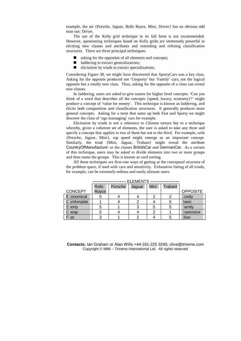
Contacts: Ian Graham or Alan Wills +44-161-225 3240; [email protected] Copyright © MMI – Trireme International Ltd. All rights reserved
example, the set {Porsche, Jaguar, Rolls Royce, Mini, Driver} has an obvious odd man out: Driver.
The use of the Kelly grid technique in its full form is not recommended. However, questioning techniques based on Kelly grids are immensely powerful in eliciting new classes and attributes and extending and refining classification structures. There are three principal techniques:
� asking for the opposites of all elements and concepts; � laddering to extract generalizations; � elicitation by triads to extract specializations.
Considering Figure 38, we might have discovered that SportyCars was a key class. Asking for the opposite produced not ‘Unsporty’ but ‘Family’ cars; not the logical opposite but a totally new class. Thus, asking for the opposite of a class can reveal new classes.
In laddering, users are asked to give names for higher level concepts: ‘Can you think of a word that describes all the concepts {speed, luxury, economy}?’ might produce a concept of ‘value for money’. This technique is known as laddering, and elicits both composition and classification structures. It generally produces more general concepts. Asking for a term that sums up both Fast and Sporty we might discover the class of ‘ego massaging’ cars for example.
Elicitation by triads is not a reference to Chinese torture but to a technique whereby, given a coherent set of elements, the user is asked to take any three and specify a concept that applies to two of them but not to the third. For example, with {Porsche, Jaguar, Mini}, top speed might emerge as an important concept. Similarly, the triad {Mini, Jaguar, Trabant} might reveal the attribute CountryOfManufacture: or the classes BritishCar and GermanCar. As a variant of this technique, users may be asked to divide elements into two or more groups and then name the groups. This is known as card sorting.
All these techniques are first-rate ways of getting at the conceptual structure of the problem space, if used with care and sensitivity. Exhaustive listing of all triads, for example, can be extremely tedious and easily alienate users.
--------------------------------------------- ELEMENTS --------------------------------------- CONCEPT
Rolls Royce
Porsche Jaguar Mini Trabant OPPOSITE
Economical 5 4 4 2 2 Costly Comfortable 1 4 2 4 5 Basic Sporty 5 1 3 5 5 Family Cheap 5 4 4 2 1 Expensive Fast 3 1 2 4 5 Slow

Contacts: Ian Graham or Alan Wills +44-161-225 3240; [email protected] Copyright © MMI – Trireme International Ltd. All rights reserved
Figure 38 A Kelly grid. Scores are between 1 and 5. The left-hand pole of the concept corresponds to a low score for the element and the right (its opposite) to a high one. The grid is not focused.
There are several computer systems which automate the construction and focusing of these grids, such as ETS (Boose, 1986) and its commercial descendant AQUINAS (Boose and Bradshaw, 1988). These systems convert the grids into sets of rules. It is curious that these automated tools throw so much of what is captured by the repertory grid analysis away. It is clear that laddering and sorting produce classification structures, for example. These are then disguised as production rules with a consequent loss of information. We predicted in 1991 that tools would evolve which would capture such structural information directly. That this did begin to happen was illustrated by the work of Gaines and Shaw (Gaines and Shaw, 1992; Shaw and Gaines, 1992) but the work is not yet commercialized to the best of our knowledge. In the interim the technique must be used manually, and preferably informally, for object-oriented analysis.
Object templates have been used in knowledge acquisition for expert systems. Filling in the templates is a structured method for gathering semantic information which is of general applicability. The knowledge engineering approach emphasizes that classes should correspond to concepts held by users and experts. High level classes represent abstractions that may be reusable across several similar domains. The abstraction ‘object’ is universal in all domains, but ‘account’ is usable across most financial and accounting applications. Mortgage account is more specialized and therefore reusable across a narrow set of applications. The key skill for analysts seeking the benefit of reuse is to pitch the abstractions at the right level. Prototyping and interaction with users and domain experts all help to elicit knowledge about objects.
Thus, ontology and epistemology help us find objects and structures. They should also help us know how to recognize a good object when we meet one, either in a library or as a result of our own efforts. The third requisite tool for this purpose is, of course, common sense. A few common-sense guidelines for object identification are worth including at this point.
� Always remember that a good reusable object represents something universal and real. An object is a social animal; its methods may be used by other classes. If not, ask what its function is or delete it from the model.
� Although an object should not be so complex as to defy comprehension, it should encapsulate some reasonably complex behaviour to justify its existence.
� A method that doesn’t make use of its current class’s own attributes is probably encapsulated in the wrong object, since it does not need access to the private implementation.
Measuring the quality of an abstraction is very difficult. Guidelines can be

Contacts: Ian Graham or Alan Wills +44-161-225 3240; [email protected] Copyright © MMI – Trireme International Ltd. All rights reserved
taken from an analogy with the design of machinery. As with a machine, there should be a minimum number of interchangeable parts and the parts should be as general as possible. Suggested criteria, with their corresponding metrics, include several that we have already met in the context of object-oriented programming.
� Interfaces should be as small, simple and stable as possible. � The object should be self-sufficient and complete; the slogan is: ‘The
object, the whole object and nothing but the object’. As a counter-example to this notion of complete objects, consider a class for objects whose names begin with the letters ‘CH’. In other words, avoid accidental objects. Objects must not need to send lots of messages to do simple things: the topology of the usage structure should be simple.
Similar guidelines apply to methods. Methods too should be simple and generative. For example, the method ‘add 1’ generates a method ‘add n’ for all n. Look for such commonalities. They should be relevant; that is, methods must be applicable to the concept, neither more specific nor more general. Methods should depend on the encapsulated state of the containing object, as mentioned above. A very important principle of object-orientation is the principle of loose coupling or the ‘Law of Demeter’ which states that ‘the methods of a class should not depend in any way on the structure of any class, except the immediate (top level) structure of their own class. Furthermore, each method should send messages to objects belonging to a very limited set of classes only’ (Sakkinen, 1988). This helps classes to be understood in isolation and therefore reused.
Recall that analysts should avoid objects arising solely from normalization or the removal of many-to-many relationships. The rule is: if it’s not a real-world entity then it’s not an object. For example, the many-to-many relationship between ORDERS and INVOICES may be removed by introducing a new class ORDER-LINE. This is fine, the lines are real things; they get printed on the invoice. On the contrary there seems to be no such natural object that would remove the many-to-many relationship between cars and the colours they may be painted.
The last point we wish to make is that analysts should not be expected to get it right first time. They never do. This is the mistake of the waterfall model, and we know all too well that the costs of maintaining incorrectly specified systems are high. Prototyping and task-centred design, if properly managed, allow the analyst to get it right; but third time round.
5 CASE tools
There are several commercial CASE tools supporting UML or aspects of UML. Most of them are drawing editors that check the syntax of UML models and often generate code from the latter. Perhaps the best known is Rose from Rational Inc.

Contacts: Ian Graham or Alan Wills +44-161-225 3240; [email protected] Copyright © MMI – Trireme International Ltd. All rights reserved
Rose starts by default with two packages, one for use case diagrams and the other for class diagrams. But this isn’t always the most sensible separation: you can put either kind of diagram into any package, and mix classes, use cases, and actors in a diagram as you judge appropriate. Use cases can be dragged onto class diagrams and vice versa. You can mix them in one diagram or not, as you prefer. Keywords, invariants and rulesets are not well supported and so one must use comments on for descriptions, rulesets, invariants and pre- and post-conditions.
In Rose, class diagrams and statecharts are always in separate diagrams. Also, Rose does not permit more than one statechart per class; if there are more, one must draw them all on one diagram.
One advantage, if such it is, of Rose is the fact that it integrates well with other Rational tools for configuration management, testing, requirements documentation and so on. There are also tools from third parties such as RoseLink, which enables C++ or Java application skeletons for the Versant OODBMS to be generated, converting associations into C++ or ODMG collections. The temptation with all such tools is to create huge diagrams. As we have argued, this is not a good idea; the ideal is a good narrative punctuated by small diagrams that help disambiguate and illustrate the text. Tools, such as Soda, can be used to help embed diagrams in the narrative. It is a good idea to put any use case specifications in the main comment box – where they are more visible – and in attached notes, or both.
A more impressive tool of the same type is Together, which comes in C++ and Java variants. TogetherJ, for example, supports genuine round-trip engineering: as you draw a diagram the Java code appears in a separate window and, better still, the diagram changes as you edit the Java code. Rose does something similar, but not nearly as well.
Computer Associates’ Paradigm Plus and its COOL suite of products also support UML diagram making. COOL Jex supports some of the Catalysis techniques. The component model underlying the COOL products is discussed by Cheesman and Daniels (2000).
Princeton Softtech’s Select, Aionix’s Software through Pictures (StP) and Popkin’s System Architect are further examples of UML-compliant CASE tools. There are also UML tools that support specific methods such as Shlaer-Mellor rather than just the UML notation.
In additional to UML and structured methods support, System Architect has features that support business modelling using the Zachman framework (Zachman, 1987; Sowa and Zachman, 1992): a widely used classification scheme for descriptive or notational representations of enterprises. The framework allocates notations to the cells of a matrix. The columns and rows are certainly a complete classification scheme – there are only those six question words. Notably, the rows are based on an analogy with building construction and represent the perspectives taken by different trades during the construction process. This can provide a useful guide, but it is difficult to see how the data/function split can be reconciled with object-orientation. In fact, as shown by Graham (1995), the framework collapses to

Contacts: Ian Graham or Alan Wills +44-161-225 3240; [email protected] Copyright © MMI – Trireme International Ltd. All rights reserved
many fewer cells when OO concepts are substituted for such representations as ‘logical data model’.
No tool yet properly supports the Catalysis framework substitution described later, although Platinum Plus may do soon; others will probably follow and the technique is likely at some stage to appear in the UML standard. TogetherJ already does something fairly similar with its support for patterns.
What is lacking mostly on the CASE scene are good object-oriented business simulation tools; these would allow one to animate business process models. We also lack what one might designate ‘anti-CASE’ tools, which can generate most UML diagrams automatically. Ideally these types of tool should be integrated into a single package and have interfaces with popular conventional CASE tools and drawing packages.
Our favourite everyday tools for drawing diagrams are the low-cost Visio and PowerPoint drawing tools. They intrude less on our thinking and allow us to innovate where necessary. UML templates for Visio are readily available.
6 Patterns, architecture and decoupled design
One of the most important recent ideas in software development is that of a design pattern. Design patterns are standard solutions to recurring problems, named to help people discuss them easily and to think about design. They have always been around in computing, so that terms such as ‘linked list’ or ‘recursive descent’ are readily understood by people in the field.
Software patterns have been described as reusable micro-architectures. Patterns are abstract, core solutions to problems that recur in different contexts but encounter the same ‘forces’ each time. The actual implementation of the solution varies with each application. Patterns are not, therefore, ready-made ‘pluggable’ solutions. They are most often represented in object-oriented development by commonly recurring arrangements of classes and the structural and dynamic connexions between them. Perhaps the best known and useful examples of patterns occur in application frameworks associated with graphical user interface building or other well-defined development problems. In fact, some of the motivation for the patterns movement came from the apprehension of already existing frameworks that led people to wonder how general the approach was. Nowadays it is more usual to deliver frameworks in the form of flexible class libraries for use by programmers in languages that support the class concept, often C++ and Java. Examples of frameworks range from class libraries that are delivered with programming environments through the NeXtStep Interface Builder to the many GUI and client-server development systems now on the market such as Delphi, Visual Studio, Visual Age or Visual Basic.
Patterns are most useful because they provide a language for designers to communicate in. Rather than having to explain a complex idea from scratch, the

Contacts: Ian Graham or Alan Wills +44-161-225 3240; [email protected] Copyright © MMI – Trireme International Ltd. All rights reserved
designer can just mention a pattern by name and everyone will know, at least roughly, what is meant. This is how designers in many other disciplines communicate their design ideas. In this sense they are an excellent vehicle for the collection and dissemination of the anecdotal and unquantifiable data that Borenstein (1991) argues need to be collected before we can see real advances in the processes of building software. As with software architecture there are two different views of patterns abroad, both of which have value. To examine these we will first look at the roots of the patterns concept which lie outside the domain of software development, in the domain of the built environment. Hardly surprising then that patterns are closely related to software architecture.
Patterns are associated with the radical architect of the built environment, Christopher Alexander. From the outset of his career Alexander has been driven by the view that the vast majority of building stock created since the end of World War II (which constitutes the great majority of all construction works created by human beings in the history of the species) has been dehumanizing, of poor quality and lacking all sense of beauty and human feeling. In his earliest publication Alexander presented a powerful critique of modern design (Alexander, 1964) contrasting the failures of the professional self-conscious process of design with what he called the unselfconscious process by which peasants’ farmhouses, Eskimos’ igloos and the huts of the Mousgoum tribesmen of the Cameroon amongst others create their living spaces. In the latter ‘…the pattern of building operation, the pattern of the building’s maintenance, the constraints of the surrounding conditions, and also the pattern of daily life, are fused in the form’ (p. 31) yet there is no concept of ‘design’ or ‘architecture’, let alone separate designers and architects. Each man builds his own house.
Alexander argues that the unselfconscious process has a homeostatic (i.e. self-organizing) structure that produces well-fitting forms even in the face of change, but in the self-conscious process this homeostatic structure has been broken down, making poorly-fitting forms almost inevitable. Although, by definition, there are no explicitly articulated rules for building in the unselfconscious process, there is usually a great weight of unspoken, unwritten, implicit rules that are, nevertheless, rigidly maintained by culture and tradition. These traditions provide a bedrock of stability, but more than that, a viscosity or resistance to all but the most urgent changes – usually when a form ‘fails’ in some way. When such changes are required the very simplicity of life itself, and the immediacy of the feedback (since the builder and homeowner are one and the same) mean that the necessary adaptation can itself be made immediately, as a ‘one-off’. Thus the unselfconscious process is characterized by fast reactions to single ‘failures’ combined with resistance to all other changes. This allows the process to make a series of minor, incremental adjustments instead of spasmodic global ones. Changes have local impact only, and over a long period of time, the system adjusts ‘subsystem by subsystem’. Since the minor changes happen at a faster rate of change than does the culture, equilibrium is constantly and dynamically re-established after each

Contacts: Ian Graham or Alan Wills +44-161-225 3240; [email protected] Copyright © MMI – Trireme International Ltd. All rights reserved
disturbance. In the self-conscious process tradition is weakened or becomes non-existent.
The feedback loop is lengthened by the distance between the ‘user’ and the builder. Immediate reaction to failure is not possible because materials are not close to hand. Failures for all these reasons accumulate and require far more drastic action because they have to be dealt with in combination. All the factors that drive the construction process to equilibrium have disappeared in the self-conscious process. Equilibrium, if reached at all, is unsustainable, not least because the rate at which culture changes outpaces the rate at which adaptations can be made.
Alexander does not seek a return to primitive forms, but rather a new approach to a modern dilemma: self-conscious designers, and indeed the notion of design itself, have arisen as a result of the increased complexity of requirements and sophistication of materials. They now have control over the process to a degree that the unselfconscious craftsman never had. But the more control they get, the greater the cognitive burden and the greater the effort they spend in trying to deal with it, the more obscure becomes the causal structure of the problem which needs to be expressed for a well-fitting solution to be created. Increasingly, the very individuality of the designer is turning into its opposite: instead of being a solution, it is the main obstacle to a solution to the problem of restoring equilibrium between form and context.
In his 1964 work, Alexander produced a semi-algorithmic, mechanistic ‘programme’ based on functional decomposition (supported by a mathematical description in an appendix) to address the issues he identified. He has long since abandoned that prescription. It is the rather more informal drawings he used in the worked example that seem to have a more lasting significance. These became the basis, it seems, for the patterns in his later work.
Alexandrian ‘theory’ is currently expressed in an 11-volume-strong literary project that does not include his 1964 work. Eight of these volumes have been published so far (though, at best, three of them, referred to as the patterns trilogy, The Timeless Way of Building, A Pattern Language and The Oregon Experiment, are familiar to parts of the software patterns movement). The ninth volume in the series, The Nature of Order, is eagerly awaited as it promises to provide the fullest exposition yet of the underlying theory. A common theme of all the books is the rejection of abstract categories of architectural or design principles as being entirely arbitrary. Also rejected is the idea that it is even possible to successfully design ‘very abstract forms at the big level’ (Alexander, 1996, p.8). For Alexander architecture attains its highest expression, not at the level of gross structure, but actually in its finest detail, what he calls ‘fine structure’. That is to say, the macroscopic clarity of design comes from a consistency; a geometric unity holds true at all levels of scale. It is not possible for a single mind to envision this recursive structure at all levels in advance of building it. It is in this context that his patterns for the built environment must be understood.
Alexander et al. (1977) present an archetypal pattern language for construction.

Contacts: Ian Graham or Alan Wills +44-161-225 3240; [email protected] Copyright © MMI – Trireme International Ltd. All rights reserved
The language is an interconnected network of 253 patterns that encapsulate design best practice at a variety of levels of scale, from the siting of alcoves to the construction of towns and cities. The language is designed to be used collaboratively by all the stakeholders in a development, not just developers. This is premised, in part at least, by the idea that the real experts in buildings are those that live and work in them rather than those that have formally studied architecture or structural engineering. The patterns are applied sequentially to the construction itself. Each state change caused by the application of a pattern creates a new context to which the next pattern can be applied. The overall development is an emergent property of the application of the pattern language. The language therefore has a generative character: it generates solutions piece-meal from the successive addressing of each individual problem that each of the patterns addresses separately.
WAIST-HIGH SHELF (number 201 in the language) is an example pattern. It proposes the building of waist-high shelves around main rooms to hold the ‘traffic’ of objects that are handled most so that they are always immediately at hand. Clearly the specific form, depth, position and so on of these shelves will differ from house to house and workplace to workplace. The implementation of the pattern creates, therefore, a very specific context in which other patterns such as THICKENING THE OUTER WALL (number 211) can be used since Alexander suggests the shelves be built into the very structure of the building where appropriate, and THINGS FROM YOUR LIFE (number 253) to populate the shelves.
The pattern which more than any other is the physical and procedural embodiment of Alexander’s approach to design, however, is pattern number 208, GRADUAL STIFFENING:
The fundamental philosophy behind the use of pattern languages is that buildings should be uniquely adapted to individual needs and sites; and that the plans of buildings should be rather loose and fluid, in order to accommodate these subtleties….
Recognize that you are not assembling a building from components like an erector set, but that you are instead weaving a structure which starts out globally complete, but flimsy; then gradually making it stiffer but still rather flimsy; and only finally making it completely stiff and strong. (Alexander et al., 1977, pp. 963–9.)
In the description of this pattern Alexander invites the reader to visualize a 50-year-old master carpenter at work. He keeps working, apparently without stopping, until he eventually produces a quality product. The smoothness of his labour comes from the fact that he is making small, sequential, incremental steps such that he can always eliminate a mistake or correct an imperfection with the next step. He compares this with the novice who with a ‘panic-stricken attention to detail’ tries to work out everything in advance, fearful of making an unrecoverable error. Alexander’s point is that most modern architecture has the character of the novice’s

Contacts: Ian Graham or Alan Wills +44-161-225 3240; [email protected] Copyright © MMI – Trireme International Ltd. All rights reserved
work, not the master craftsman’s. Successful construction processes, producing well-fitting forms, come from the postponement of detail design decisions until the building process itself so that the details are fitted into the overall, evolving structure.
Alexander’s ideas seem to have been first introduced into the object-oriented community by Kent Beck and Ward Cunningham. In a 1993 article in Smalltalk Report Beck claimed to have been using patterns for six years already, but the software patterns movement seems to have been kicked off by a workshop on the production of a software architect’s handbook organized by Bruce Anderson for OOPSLA’91. Here met for the first time Erich Gamma, Richard Helm, Ralph Johnson and John Vlissides – a group destined to gain notoriety as the Gang of Four (GoF). Gamma was already near to completion of his PhD thesis on ‘design patterns’ in the ET++ framework (Gamma, 1992). He had already been joined by Helm in the production of an independent catalogue. By the time of a follow-up meeting at OOPSLA in 1992, first Vlissides and then Johnson had joined the effort and, sometime in 1993, the group agreed to write a book that has been a best-seller ever since its publication in 1995. In fact, outside the patterns movement itself, many in the software development industry identify software patterns completely and totally with the GoF book.
However, the 1991 OOPSLA workshop was only the first in a series of meetings that culminated first in the formation of the non-profit Hillside Group (apparently so-called because they went off to a hillside one weekend to try out Alexander’s building patterns) and then the first Pattern Languages of Programming (PLoP) conference in 1994. PLoP conferences, organized and funded by the Hillside Group, take place annually in America, Germany and Australia and collections of the patterns that are produced are published in a series by Addison-Wesley – four volumes to date. In addition the Hillside Group maintains a web site and numerous pattern mailing lists (Hillside Group, 2000). These communication channels form the backbone of a large and growing community that is rightly called the patterns movement.
A characteristic of the way patterns are developed for publication in the patterns movement is the so-called pattern writers’ workshop. This is a form of peer-review which is loosely related to design reviews that are typical in software development processes, but more strongly related to poetry circles which are decidedly atypical. The special rules of the pattern writers’ workshop (which are the modus operandi of the PLoP conferences) have been shown to be powerful in producing software patterns, written in easily accessible, regular forms known as pattern templates, at an appropriate level of abstraction. Rising (1998) reports on their effectiveness in producing a patterns’ culture in the telecommunications company AGCS; and they are de rigeur in parts of IBM, Siemens and AT&T, all of which are known to have produced their own in-house software patterns, as well as publishing them in the public domain.
While the GoF book has won deserved recognition for raising the profile of
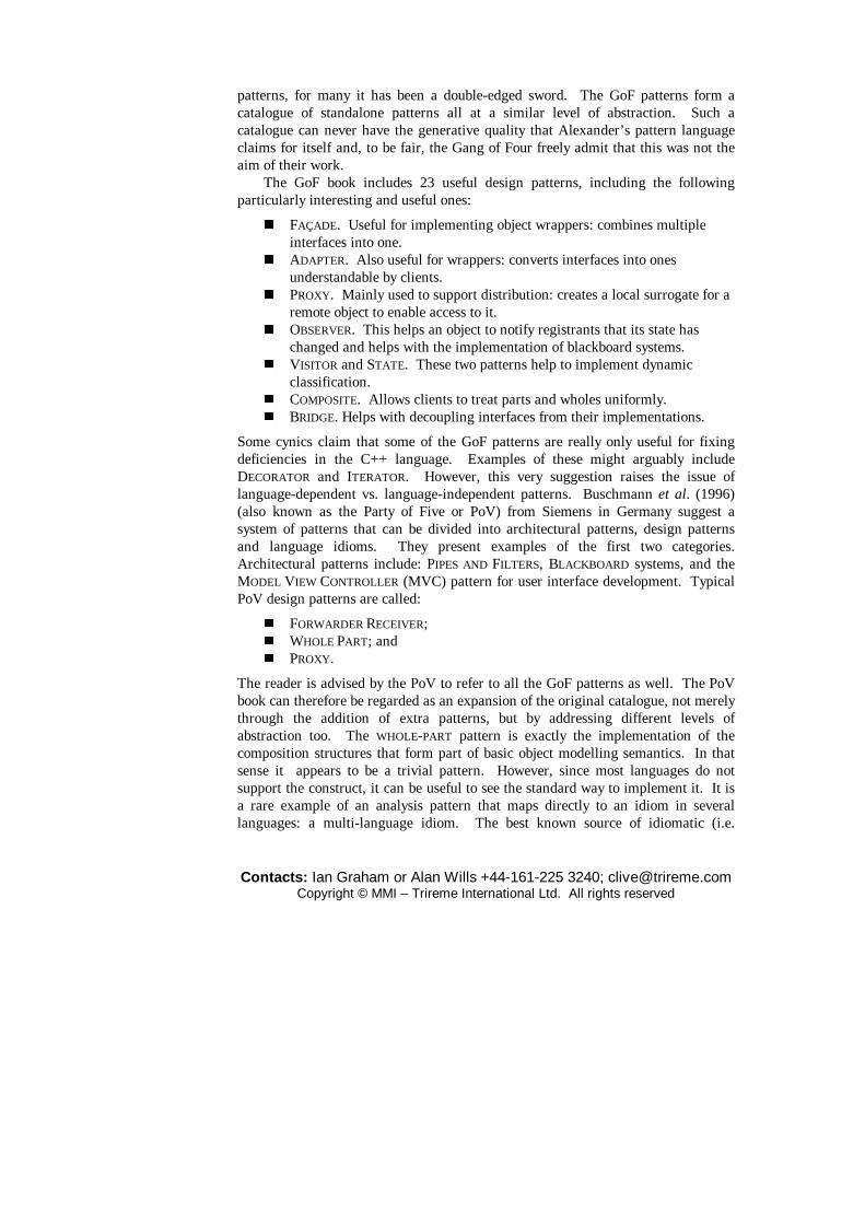
Contacts: Ian Graham or Alan Wills +44-161-225 3240; [email protected] Copyright © MMI – Trireme International Ltd. All rights reserved
patterns, for many it has been a double-edged sword. The GoF patterns form a catalogue of standalone patterns all at a similar level of abstraction. Such a catalogue can never have the generative quality that Alexander’s pattern language claims for itself and, to be fair, the Gang of Four freely admit that this was not the aim of their work.
The GoF book includes 23 useful design patterns, including the following particularly interesting and useful ones:
� FAÇADE. Useful for implementing object wrappers: combines multiple interfaces into one.
� ADAPTER. Also useful for wrappers: converts interfaces into ones understandable by clients.
� PROXY. Mainly used to support distribution: creates a local surrogate for a remote object to enable access to it.
� OBSERVER. This helps an object to notify registrants that its state has changed and helps with the implementation of blackboard systems.
� VISITOR and STATE. These two patterns help to implement dynamic classification.
� COMPOSITE. Allows clients to treat parts and wholes uniformly. � BRIDGE. Helps with decoupling interfaces from their implementations.
Some cynics claim that some of the GoF patterns are really only useful for fixing deficiencies in the C++ language. Examples of these might arguably include DECORATOR and ITERATOR. However, this very suggestion raises the issue of language-dependent vs. language-independent patterns. Buschmann et al. (1996) (also known as the Party of Five or PoV) from Siemens in Germany suggest a system of patterns that can be divided into architectural patterns, design patterns and language idioms. They present examples of the first two categories. Architectural patterns include: PIPES AND FILTERS, BLACKBOARD systems, and the MODEL VIEW CONTROLLER (MVC) pattern for user interface development. Typical PoV design patterns are called:
� FORWARDER RECEIVER; � WHOLE PART; and � PROXY.
The reader is advised by the PoV to refer to all the GoF patterns as well. The PoV book can therefore be regarded as an expansion of the original catalogue, not merely through the addition of extra patterns, but by addressing different levels of abstraction too. The WHOLE-PART pattern is exactly the implementation of the composition structures that form part of basic object modelling semantics. In that sense it appears to be a trivial pattern. However, since most languages do not support the construct, it can be useful to see the standard way to implement it. It is a rare example of an analysis pattern that maps directly to an idiom in several languages: a multi-language idiom. The best known source of idiomatic (i.e.

Contacts: Ian Graham or Alan Wills +44-161-225 3240; [email protected] Copyright © MMI – Trireme International Ltd. All rights reserved
language-specific) patterns is Jim Coplien’s book on advanced C++ which predates the GoF book by some three years (Coplien, 1992). C++ ‘patterns’ (the book does not use the term) that Coplien presents include:
� HANDLE CLASS, used to encapsulate classes that bear application intelligence;
� REFERENCE COUNTER, managing a reference count to shared representation;
� ENVELOPE-LETTER permits ‘type migration’ of classes; � EXEMPLAR enables the creation of prototypes in the absence of delegation; � AMBASSADOR provides distribution transparency.
Whilst experienced object-oriented programmers will feel immediately familiar with many of these patterns, almost everyone will recognize the ideas behind caches and recursive composites. These too can be regarded as design and/or analysis patterns. CACHE should be used when complex computations make it better to store the results rather than recalculate often; or when the cost of bringing data across a network makes it more efficient to store them locally. Clearly this is a pattern having much to do with performance optimization. It is also worth noting that patterns may use each other; this pattern may make use of the OBSERVER pattern (see below) when it is necessary to know that the results need to be recalculated or the data refreshed. This can be done eagerly or lazily, depending on the relative read and update profiles.
Although it is often good practice – unless dealing with derived dependencies – to document structures such as inheritance and aggregation separately, as we saw earlier, documenting patterns often requires that they are expressed in terms of more than one structure. Recursive, extensible structures such as binary trees and lists are a good example: a list is recursively composed of an atomic head and a tail which is itself a list, and a program is made up of primitive statements and blocks that are themselves made of blocks and statements. We can use a Catalysis framework template to document a general case as in Figure 38, in which one might substitute Block for <Node>, Program for <Branch> and Statement for <Leaf>.

Contacts: Ian Graham or Alan Wills +44-161-225 3240; [email protected] Copyright © MMI – Trireme International Ltd. All rights reserved
<Node>
<Leaf><Branch>parent
0..*
child
Figure 38 Recursive composites. We process recursive structures by recursive descent and need to specify – in
the template – whether looping is prevented by including constraints. In OCL such a constraint can be written:
context Node::ancestors = parent + parent.ancestors AND context Node:: not(ancestors includes self) Strictly speaking, addition is not defined over sets in OCL. The plus sign is an
abbreviation introduced in Catalysis, with the advantage of symmetry. The correct OCL form is: Set1 −> union(Set2).
The list and the block patterns can be regarded as whole objects or wrappers and the pattern merely describes their internal structure.
The above examples indicate that a standard pattern layout may be beneficial, and many proponents adopt a standard based on Alexander’s work: the so-called Alexandrian form. This divides pattern descriptions into prose sections with suitable pictorial illustrations as follows – although the actual headings vary from author to author.
� Pattern name and description. � Context (Problem) – situations where the patterns may be useful and the
problem that the pattern solves. � Forces – the contradictory forces at work that the designer must balance. � Solution – the principles underlying the pattern and how to apply it
(including examples of its realization, consequences and benefits). � Also Known As/Related patterns – other names for (almost) the same thing
and patterns that this one uses or might occur with. � Known uses.
Kent Beck has produced a book of 92 Smalltalk idioms (Beck, 1997) and there have been a number of language-specific ‘versions’ of the GoF book, notably for Smalltalk (Alpert et al., 1998) and Java (Grand, 1998; Cooper, 2000). Although many of the PoV architectural patterns exist also among the SEI’s ‘styles’, it is crucial to note their different purposes. Both are abstracted from software development best practice, but by the SEI in order to collect and formalize (and

Contacts: Ian Graham or Alan Wills +44-161-225 3240; [email protected] Copyright © MMI – Trireme International Ltd. All rights reserved
presumably later automate) them, by the PoV in order to further generalize that practice.
The overwhelming majority of software patterns produced to date have been design patterns at various levels of abstraction but Fowler (1997) introduces the idea of analysis patterns as opposed to design patterns. Fowler’s patterns are reusable fragments of object-oriented specification models made generic enough to be applicable across a number of specific application domains. They therefore have something of the flavour of the GoF pattern catalogue (described in that book’s subtitle as ‘elements of reusable object-oriented software’) but are even further removed from Alexander’s generative concepts. Examples of Fowler’s patterns include:
� PARTY: how to store the name and address of someone or something you deal with.
� ORGANIZATION STRUCTURE: how to represent divisional structure. � POSTING RULES: how to represent basic bookkeeping rules. � QUOTE: dealing with the different ways in which financial instrument
prices are represented.
There are many more, some specialized into domains such as Health or Accounting. The problem with these patterns is that even the simplest ones – like
ACCOUNTABILITY – are really quite hard to understand compared to the difficulty of the underlying problem that they solve. One of us had three goes at reading the text before really understanding what was going on. At the end of this process he found that he knew the proposed solution already but would never have expressed it in the same terms.
Maiden et al. (1998) propose a pattern language for socio-technical system design to inform requirements validation thereof, based on their CREWS-SAVRE prototype. They specify three patterns as follows:
� MACHINE-FUNCTION: this represents a rule connecting the presence of a user action (a task script in our language) to a system requirement to support that action (an operation of a business object that implements the task). We feel that it is stretching language somewhat to call this rule a pattern.
� COLLECT-FIRST-OBJECTIVE-LAST: this pattern tells us to force the user to complete the prime transaction after the subsidiary ones; e.g. ATMs should make you take the card before the cash.
� INSECURE-SECURE-TRANSACTION: this suggests that systems should monitor their security state and take appropriate action if the system becomes insecure.
The value of these patterns may be doubted because, like Fowler’s analysis patterns, they seem to state the obvious; and they fail to address the sort of task or system usage patterns represented by our task association sets or use case refinement. Also,
Contacts: Ian Graham or Alan Wills +44-161-225 3240; [email protected] Copyright © MMI – Trireme International Ltd. All rights reserved
it could be argued that they are nothing but design principles; just as completion provides a well-known design principle in HCI. On the other hand, their operationalization in the CREWS-SAVRE system indicates that they may have a specialized practical value in this and certain other contexts. There has also been interest in developing patterns for organizational development (Coplien, 1995; O’Callaghan, 1997, 1997a, 1998). Coplien applies the idea of patterns to the software development process itself and observes several noteworthy regularities. These observations arose out of a research project sponsored by AT&T investigating the value of QA process standards such as ISO9001 and the SEI’s Capability Maturity Model. Working from a base concept that real processes were characterized by their communication pathways, Coplien, together with Brad Cain and Neil Harrison, analysed more than 50 projects by medium-size, high productivity software development organizations, including the Borland team charged with developing the Quattro Pro spreadsheet product. The technique they used was to adapt CRC cards and to get, in a workshop situation, representatives of the development organization under focus to enumerate rôles (as opposed to job descriptions), identify and categorize the strength of the relationships between those rôles (as either Weak, Medium and Strong) and then to rôle-play the development process in order to validate their judgements. The information was then input into a Smalltalk-based system called Pasteur that produces a variety of different sociometric diagrams and measures. From these, Coplien et al. were able to identify the commonly recurring key characteristics of the most productive organizations and develop a 42-strong pattern language to aid the design of development organizations. Included in the language are patterns such as these:
� CONWAY’S LAW states that architecture always follows organization or vice versa;
� ARCHITECT ALSO IMPLEMENTS requires that the architect stands close to the development process;
� DEVELOPER CONTROLS PROCESS requires that the developers own and drive the development process, as opposed to having one imposed on them;
� MERCENARY ANALYST enables the ‘off-line’ reverse engineering and production of project documentation;
� FIREWALL describes how to insulate developers from the ‘white noise’ of the software development industry;
� GATEKEEPER describes how to get useful information in a timely manner to software developers.
A typical application of such organizational patterns is the combined use of GATEKEEPER and FIREWALL in, say, a situation where a pilot project is assessing new technology. The software development industry excels at rumour-mongering, a situation fuelled by the practice of vendors who make vapourware announcements long in advance of any commercial-strength implementations. Over-attention to the whispers on the industry grapevine, let alone authoritative-looking statements in the

Contacts: Ian Graham or Alan Wills +44-161-225 3240; [email protected] Copyright © MMI – Trireme International Ltd. All rights reserved
trade press, can seriously undermine a pilot project. Developers lose confidence in Java, say, because of its reputation for poor performance or a claimed lack of available tools. Yet, at the same time, some news is important: for example, the publication of Platform 2 for Java. A solution is to build official firewalls and then create a gatekeeper rôle where a nominated individual, or perhaps a virtual centre such as an Object Centre, is responsible for filtering and forwarding the useful and usable information as opposed to unsubstantiated scare stories, junk mail and even the attention of vendors’ sales forces.
More interesting than the individual patterns themselves, however, is the underlying approach of Coplien’s language which is much closer to the spirit of Alexander’s work than anything to be found in the GoF or PoV books, for example. First, since its very scope is intercommunication between people, it is human-centred. Second, it is explicitly generative in its aim. Coplien argues that while software developers do not inhabit code in the way that people inhabit houses and offices, as professionals they are expert users of professional processes and organizations. Therefore, just as Alexander’s language is designed to involve all the stakeholders of building projects (and, above all, the expertise of the users of the buildings) so process designers have to base themselves on the expertise of the victims of formal processes – the developers themselves. Coplien’s attempt to create an avowedly Alexandrian pattern language seems to push the focus of his patterns away from descriptions of fragments of structure (as is typical in the GoF patterns) much more towards descriptions of the work that has to be done. In going beyond mere structure Coplien’s patterns have much more of a feel of genuine architecture about them than do many other pattern types available.
In fact, it is clear that from common roots there are two polarized views of patterns abroad today. One view focuses on patterns as generic structural descriptions. They have been described, in UML books especially, as ‘parameterized collaborations’. The suggestion is that you can take, say, the structural descriptions of the rôles that different classes can play in a pattern and then, simply by changing the class names and providing detailed algorithmic implementations, plug them into a software development. Patterns thus become reduced to abstract descriptions of potentially pluggable components. A problem with this simplistic view occurs when a single class is required to play many rôles simultaneously in different patterns. Erich Gamma has recently re-implemented the HotDraw framework, for example, in Java. One class, Figure, appears to collaborate in fourteen different overlapping patterns – it is difficult to see how the design could have been successful if each of these patterns had been instantiated as a separate component. More importantly, this view has nothing to say about how software projects should be put together, only what (fragments of) it might look like structurally. The other view regards them simply as design decisions (taken in a particular context, in response to a problem recognized as a recurring one). This view inevitably tends toward the development of patterns as elements in a generative pattern language.

Contacts: Ian Graham or Alan Wills +44-161-225 3240; [email protected] Copyright © MMI – Trireme International Ltd. All rights reserved
Support for this comes from the work of Alan O’Callaghan and his colleagues in the Object Engineering and Migration group and Software Technology Research Laboratory at De Montfort University. O’Callaghan is the lead author of the ADAPTOR pattern language for migrating legacy systems to object and component-based structures. ADAPTOR was based initially on five projects, starting in 1993, in separate business areas and stands for Architecture-Driven And Patterns-based Techniques for Object Re-engineering. It currently encapsulates experiences of eight major industrial projects in four different sectors: telecommunications, the retail industry, defence and oil exploration. O’Callaghan argues that migrating to object technology is more than mere reverse engineering, because reverse engineering is usually (a) formal and (b) focused purely on the functional nature of the legacy systems in question and (c) assumes a self-similar architecture to the original one. The most crucial information, about the original design rationales, has already been lost irretrievably. It cannot be retrieved from the code because the code never contained that information (unless, of course, it was written in an unusually expressive way). The best that traditional archaeological approaches to reverse engineering can achieve is to recreate the old system in an object-oriented ‘style’ which, more often than not, delivers none of the required benefits.
The approach, pioneered by Graham (1995) and O’Callaghan, was to develop object models of the required ‘new’ system and the legacy system and, by focusing on the maintainers and developers (including their organizational structure) rather than the code or design documentation, determine only subsequently what software assets might already exist that could be redeployed. O’Callaghan’s group turned to patterns in the search for some way of documenting and communicating the common practices that were successful in each new project (legacy systems present especially wicked problems and are, overall, always unique unto themselves). At first, public domain, standalone design patterns were used but quickly his team were forced to mine their own. Then problems of code ownership (i.e. responsibility for part of a system being re-engineered belonging to someone other than the immediate client), caused by the fact that migrations typically involve radical changes at the level of the gross structure of a system, required that organizational and process problems be addressed also through patterns. Finally, observations that the most powerful patterns in different domains were interconnected suggested the possibility of a generative pattern language.
ADAPTOR was announced in 1998 as a ‘candidate, open, generative pattern language’. It is a candidate language for two reasons: first, despite the overwhelming success of the projects from which it is drawn ADAPTOR is not comprehensive enough in its coverage or recursed to a sufficient level of detail to be, as yet, truly generative. Secondly, O’Callaghan has different level of confidence in the different patterns with only those having gone through the patterns workshops of the patterns movement being regarded as fully mature. Patterns yet to prove themselves in this way are regarded as candidate patterns. ADAPTOR is open in a number of senses too. First, like any true language, both the language itself

Contacts: Ian Graham or Alan Wills +44-161-225 3240; [email protected] Copyright © MMI – Trireme International Ltd. All rights reserved
and the elements that comprise it are evolvable. Many of the most mature patterns, such as GET THE MODEL FROM THE PEOPLE, which was first presented in 1996 at a TelePlop workshop, have gone through numbers of iterations of change. Secondly, following Alexander et al. (1977), O’Callaghan insists that patterns are open abstractions themselves. Since no true pattern provides a complete solution and every time it is applied it delivers different results (because of different specific contexts to which it is applied), it resists the kind of formalization that closed abstractions such as rules can be subject to. Finally, and uniquely amongst published software pattern languages, ADAPTOR is open because it makes explicit use of other public-domain pattern languages and catalogues, such as Coplien’s generative development-process language already cited, or the GoF and PoV catalogues.
Patterns in ADAPTOR include the following.
� GET THE MODEL FROM THE PEOPLE requires utilization of the maintainers of a legacy system as sources of business information.
� PAY ATTENTION TO THE FOLKLORE treats the development/maintenance communities as domain experts, even if they don’t do so themselves.
� BUFFER THE SYSTEM WITH SCENARIOS gets the main business analysts, marketers, futurologists, etc. to rôle-play alternative business contexts to the one they bet on in their requirements specifications.
� SHAMROCK divides a system under development into three loosely coupled ‘leaves’ – each of which could contain many class categories or packages; the leaves are the conceptual domain (the problem space objects), the infrastructure domain (persistence, concurrency, etc.) and the interaction domain (GUIs, inter-system protocols, etc.).
� TIME-ORDERED COUPLING clusters classes according to common change rates to accommodate flexibility to change.
� KEEPER OF THE FLAME sets up a rôle whereby the detailed design decisions can be assured to be in continuity with the architecture – changes to the gross structure are permitted if deemed necessary and appropriate.
� ARCHETYPE creates object types to represent the key abstractions discovered in the problem space.
� SEMANTIC WRAPPER creates wrappers for legacy code that present behavioural interfaces of identifiable abstractions to the rest of the system.
Something of the open and generative character aspired to by ADAPTOR can be gained from looking at the typical application of patterns to the early phases of a legacy system migration project. Underpinning ADAPTOR is the model-driven approach described earlier. O’Callaghan’s problem space models comprise object types and the relationships between them, which capture the behaviour of key abstractions of the context of the system as well as the system itself. ARCHETYPE is therefore one of the first patterns used, along with GET THE MODEL FROM THE PEOPLE
and PAY ATTENTION TO THE FOLKLORE. At an early stage strategic ‘what-if’

Contacts: Ian Graham or Alan Wills +44-161-225 3240; [email protected] Copyright © MMI – Trireme International Ltd. All rights reserved
scenarios are run against this model using BUFFER THE SYSTEM WITH SCENARIOS. SHAMROCK is applied in order to decouple the concept domain object types from the purely system resources needed to deliver them at run time. The concept domain ‘leaf’ can then be factored into packages using TIME-ORDERED COUPLING to keep types with similar change rates (discovered through the scenario-buffering) together. Coplien’s CONWAY’S LAW is now utilized to design a development organization that is aligned with the evolving structure of the system. CODE
OWNERSHIP (another Coplien pattern) makes sure that every package has someone assigned to it with responsibility for it. An ADAPTOR pattern called TRACKABLE
COMPONENT ensures that these ‘code owners’ are responsible for publishing the interfaces of their packages that others need to develop to, so that they can evolve in a controlled way. The GoF pattern FAÇADE is deployed to create a scaffolding for the detailed structure of the system. It is at this point that decisions can be made as to which pieces of functionality require new code and which can make use of legacy code. The scaffolding ensures that these decisions, and their implementation consequences, can be dealt with at a rate completely under the control and at the discretion of the development team without fear of runaway ripple effects. For the latter, SEMANTIC WRAPPERs are used to interface the old legacy stuff to the new object-oriented bits.
Even with this cursory example we can see how the language addresses all of the important issues of architecture (client’s needs, conceptual integrity, structure, process and organization, etc.) as well as getting quickly to the heart of the issues of legacy migration. O’Callaghan reports that, when outlining this approach at a public tutorial, one member of the audience objected that the model-driven approach was not re-engineering at all but just ‘forward engineering with the reuse of some legacy code’. In reply, O’Callaghan agreed and stated that that was just the point. On further consideration, he decided that many of ADAPTOR’s patterns were not specific to legacy migration at all. As a result ADAPTOR is currently being regarded as a subset of a more general language on architectural praxis for software development in a project codenamed the Janus project (O’Callaghan, 2000b).
The debate about the nature of software patterns (‘parametrized collaborations’ versus ‘design decisions’; pattern catalogues versus pattern languages) itself both reflects, and affects, the debates about software architecture. That relationship has been sharply exposed by Coplien’s guest editorship of IEEE Software magazine in the Autumn of 1999. The issue was a special feature on software architecture in which Coplien published, amongst others, Alexander’s keynote talk to the OOPSLA conference in San Jose, California in 1996 (Alexander, 1999). In his editorial, re-evaluating the architectural metaphor, Coplien identified two fundamental approaches to software development: the ‘blueprint’ or ‘masterplan’ approach versus that of ‘piecemeal growth’ (Coplien, 1999). Coplien suggests that the immature discipline of software architecture is suffering from ‘formal envy’ and has borrowed inappropriate lessons from both the worlds of hardware engineering and
Contacts: Ian Graham or Alan Wills +44-161-225 3240; [email protected] Copyright © MMI – Trireme International Ltd. All rights reserved
the built environment. Symptoms of its crisis are the separation of the deliverables of architecture from the artefacts delivered to the customer and the reification of architecture as a separate process in a waterfall approach to software development. Following the architect of the built environment Ludwig Miles van der Rohe, Coplien proclaims, as does Alexander as we have seen, that ‘God lives in the details’ and that clarity at the macro level can only be judged by whether it incorporates the fine details successfully. He further asserts: ‘The object experience highlights what had been important all along: architecture is not so much about software, but about the people who write the software’ (p. 41).
The main point about coupling and cohesion is that it permits people to work socially to produce a piece of software and both recognize and value their own particular contribution. Coplien points to CRC cards and their use in object-oriented development as the classic example of software design’s anthropomorphic nature. From this perspective, software patterns were the next wave in the advance of a software architectural practice of this kind. As Coplien quite rightly points out, the patterns movement has always celebrated the otherwise lowly programmer as the major source of architectural knowledge in software development. Beyond that it recognizes the deep character of the relationship between code’s structure and the communication pathways between the people developing and maintaining it. In doing so, Coplien argues, patterns have taken software development beyond the naïve practice of the early days of objects, which fell short of its promise because it was still constrained by a purely modular view of software programs, inherited from the previous culture. Further advance requires liberation from the weight of ‘the historic illusions of formalism and planning’ (p. 42).
Richard Gabriel, who is currently a member of the Hillside Group, a master software practitioner as well as a practising poet, suggests that there are two reasons why all successful software development is in reality piecemeal growth. First, there is the cognitive complexity of dealing not only with current, but possible future, causes of change which make it impossible to completely visualize a constructible software program in advance to the necessary level of detail with any accuracy (Gabriel, 1996). Second, there is the fact that pre-planning alienates all but the planners. Coplien, Gabriel and the entire patterns movement are dedicated to developing practices that combat this social alienation. In doing so they impart a profound social and moral obligation to the notion of software architecture. In the face of these stark realities the only alternative to piecemeal growth is the one once offered by David Parnas: fake the blueprints by reverse engineering them once the code is complete.
6.1 Design patterns for decoupling
To get the true benefits of polymorphism – or ‘pluggability’ – in a program, it is important to declare variables and parameters not with explicit classes, but via an

Contacts: Ian Graham or Alan Wills +44-161-225 3240; [email protected] Copyright © MMI – Trireme International Ltd. All rights reserved
interface (abstract class in C++, interface in Java, deferred class in Eiffel). Looking at the metaphor of a café used in Figure 39, our initial model has Food used by both Kitchen and Cash Register. But these clients need different behaviour from Food, so we separate their requirements into different interfaces: Edible for the kitchen’s requirements of food, and Saleable for the till’s. By doing this, we have made the design more flexible – and the business too: because now we can consider edible things that are not saleable (ingredients such as flour), and saleable things that are not edible – we could start selling newspapers in our café. Our original Food class happens to implement both interfaces. Some good programmers insist that we should always use interfaces to declare variables and parameters. Simple multiple inheritance of rôle-types can be considered a pattern for composing collaborations. (In untyped languages such as Smalltalk, the difference appears only in our design model, and does not appear in the program.)
Using interfaces is the basic pattern for reducing dependencies between classes. A class represents an implementation; an interface represents the specification of what a particular client requires. So declaring an interface pares the client’s dependency on others down to the minimum: anything will do that meets the specification represented by the interface.
Kitchen <<interface>> Edible
getNamegetRecipecook
<<interface>> Saleable
getNamegetPricesell
Cash Register
Food
«implements»
Ingredient Newspaper
«implements»
Kitchen Food
getRecipegetPricecooksellgetName
Cash Register
getName getRecipe cook
getName getPrice sell
Figure 39 Interface decoupling. When we add a new class to a program, we want to alter code at as few places as

Contacts: Ian Graham or Alan Wills +44-161-225 3240; [email protected] Copyright © MMI – Trireme International Ltd. All rights reserved
possible. Therefore, one should minimize the number of points where classes are explicitly mentioned. As we have discussed, some of these points are in variable and parameter declarations: use interface names there instead. The other variation points are where new instances are created. An explicit choice of class has to be made somewhere (using new Classname, or in some languages, by cloning an existing object).
FACTORY patterns are used to reduce this kind of dependency. We concentrate all creations into a factory. The factory’s responsibility is to know what classes there are, and which one should be chosen in a particular case. The factory might be a method, or an object (or possibly one rôle of an object that has associated responsibilities). As a simple example, in a graphical editor, the user might create new shapes by typing ‘c’ for a new circle, ‘r’ for a new rectangle and so on. Somewhere we must map from keystrokes to classes, perhaps using a switch statement or in a table. We do that in the shape factory, which will typically have a method called something like make ShapeFor(char keystroke). Then, if we change the design to permit a new kind of shape, we would add the new class as a subclass of Shapes and alter the factory. More typically, there will be a menu that initializes from a table of icons and names of shape types.
Normally one would have a separate factory for each variable feature of the design: one factory for creating shapes and a separate one for creating pointing-device handlers.
A separate factory class can have subclasses. Different subclasses can provide different responses as to which classes should be created. For example, suppose we permit the user of a drawing editor to change mode between creating plain shapes and creating decorated ones. We add new classes like FancyTriangles to accompany the plain ones but, instead of providing new keystrokes for creating them explicitly, we provide a mode switch – whose effect is to alter this pointer in the Editor: ShapeFactory shapeFactory;
Normally, this points to an instance of PlainShapeFactory, which implements ShapeFactory. When given the keystroke ‘c’ or the appropriate file segment, this factory creates a normal circle. But we can reassign the pointer to an instance of FancyShapeFactory, which, given the same input, creates a FancyCircle. Gamma et al. (1995) call classes like ShapeFactory ABSTRACT FACTORIES. It declares all the factory messages like makeShapeFor(keystroke), but its subclasses create different versions. Programmers new to object-oriented design can get over-enthusiastic about inheritance. A naïve analysis of a hotel system might conclude that there are several kinds of hotel, which allocate rooms to guests in different ways; and a naïve designer might therefore create a corresponding set of subclasses of Hotel in the program code, overriding the room-allocation method in the different subclasses:
class Hotel {...

Contacts: Ian Graham or Alan Wills +44-161-225 3240; [email protected] Copyright © MMI – Trireme International Ltd. All rights reserved
public void checkInGuest(...) ... abstract protected Room allocateRoom (...); ...} class LeastUsedRoomAllocatingHotel extends Hotel { protected Room allocateRoom (...) { // allocate least recently used room ...} } class EvenlySpacedRoomAllocatingHotel extends Hotel { protected Room allocateRoom (...) { // allocate room furthest from other occupied
This is not a very satisfactory tactic: it cannot be repeated for other variations in requirements, for example if there are several ways of paying the staff. Overriding methods is one of the shortest blind alleys in the history of object-oriented programming. In practice, it is useful only within the context of a few particular patterns (usually those concerned with providing default behaviour). Instead, the trick is to move each separate behavioural variation into a separate object. We define a new interface for room allocation, for staff payment, and so on; and then define various concrete implementations for them. For example, we might write:
class Hotel { Allocator allocator; ... public void checkInGuest (...) {... allocator.doAllocation(...);..} ...} interface Allocator{ Room doAllocation (...); // returns a free room ...} class LeastUsedAllocator implements Allocator { Room doAllocation (...) {...code ...}} class EvenSpaceAllocator implements Allocator { Room doAllocation (...) {...code ...}}
This pattern of moving behaviour into another object is called DELEGATION. It has some variants, described differently depending on your purpose. One benefit of delegation is that it’s possible to change the room allocator (for example) at run time, by ‘plugging in’ a new Allocator implementation to the allocator variable. Where the objective is to do this frequently, the pattern is called STATE.
Another application of DELEGATION is called POLICY: this separates business-dependent routines from the core code; so that it is easy to change them. Room allocation is an example. Another style of POLICY checks, after each operation on an object, that certain business-defined constraints are matched, raising an exception and cancelling the operation if not. For example, the manager of a hotel in a very repressed region of the world might wish to ensure that young people of opposite genders are never assigned rooms next to each other; the rule would need to be checked whenever any room-assigning operation is done.

Contacts: Ian Graham or Alan Wills +44-161-225 3240; [email protected] Copyright © MMI – Trireme International Ltd. All rights reserved
Interfaces decouple a class from explicit knowledge of how other objects are implemented; but in general there is still some knowledge of what the other object does. For example, the RoomAllocator interface includes allocateRoom(guest) – it is clear what the Hotel expects from any RoomAllocator implementation. But sometimes it is appropriate to take decoupling a stage further, so that the sender of a message does not even know what the message will do. For example, the hotel object could send a message to interested parties whenever a room is assigned or becomes free. We could invent various classes to do something with that information: a counter that tells us the current occupancy of a room, a reservations system, an object that directs the cleaning staff, and so on.
These messages are called events. An event conveys information; unlike the normal idea of an operation, the sender has no particular expectations about what it will do; that is up to the receiver. The sender of an event is designed to be able to send it to other parties that register their interest; but it does not have to know anything about their design. Events are a very common example of decoupling.
To be able to send events, an object has to provide an operation whereby a client can register its interest; and it has to be able to keep a list of interested parties. Whenever the relevant event occurs, it should send a standard notification message to each party on the list.
An extension of the EVENT pattern is OBSERVER. Here the sender and listener are called Subject and Observer, and an event is sent whenever a change occurs in the sender’s state. By this means, the observers are kept up to date with changes in the subject. New observers may be added easily as subtypes as shown in Figure 40.
Observer supertype
Observer1
notify
register(this)
0..*
Observer2
notify register(Observer supertype)
Subject
Figure 40 OBSERVER. A very common application of OBSERVER is in user interfaces: the display on
the screen is kept up to date with changes in the underlying business objects. Two great benefits of this usage are:
1. the user interface can easily be changed without affecting the business logic; 2. several views of a business object can be in existence at a time – perhaps
different classes of view.

Contacts: Ian Graham or Alan Wills +44-161-225 3240; [email protected] Copyright © MMI – Trireme International Ltd. All rights reserved
For example, a machine design can be displayed both as an engineering drawing and as a bill of materials; any changes made via one view are immediately reflected in the other. Users of word processors and operating systems are also familiar with changes made in one place – perhaps to a file name – appearing in another. It is only very old technology in which a view needs to be prompted manually to reflect changes made elsewhere. Another common use of OBSERVER is in blackboard systems.
The OBSERVER pattern has its origin in the MODEL-VIEW-CONTROLLER (MVC) pattern (or ‘paradigm’ as it is often mistakenly called), first seen in the work of Trygve Reenskaug on Smalltalk in the 1970s, and now visible in the Java AWT and Swing libraries. The MVC metaphor also influenced several object-oriented and object-based visual programming languages such as Delphi and Visual Basic.
An MVC model is an object in the business part of the program logic: not to be confused with our other use of the term ‘modelling’. A view is an observer whose job it is to display the current state of the model on the screen, or whatever output device is in use: keeping up to date with any changes that occur. In other words, it translates from the internal representation of the model to the human-readable representation on the screen. Controller objects do the opposite: they take human actions, keystrokes and mouse movements, and translate them into operations that the model object can understand. Note, in Figure 41, that OBSERVER sets up two-way visibility between model and controller as well as model and view. Controllers are not visible to views, although part of a view may sometimes be used as a controller: cells in a spreadsheet are an example.
Business object(Model)
visible properties
Observer ObserverSubject
property
updates
Controller
translates fromuser input to
businessoperations
business operations
business_op1business_op2
View
translates frombusiness
properties tooutput form
Figure 41 MODEL-VIEW-CONTROLLER instantiates OBSERVER. Views are often nested, since they represent complex model objects, which form
whole–part hierarchies with others. Each class of controller is usually used with a particular class of views, since the interpretation of the user’s gestures and typing is usually dependent on what view the mouse is pointing at. In MVC, View and Controller are each specializations of the ADAPTER pattern (not

Contacts: Ian Graham or Alan Wills +44-161-225 3240; [email protected] Copyright © MMI – Trireme International Ltd. All rights reserved
to be confused with the ADAPTOR pattern language). An adapter is an object that connects two classes that were designed in ignorance of each other, translating events issued by one into operations on the other. The View translates from the property change events of the Model object to the graphical operations of the windowing system concerned. A Controller translates from the input events of the user’s gestures and typing to the operations of the Model.
An adapter knows about both of the objects it is translating between; the benefit that it confers is that neither of them needs to know about the other, as we can see from the package dependency diagram in Figure 42.
Any collection of functions can be thought of as an adapter in a general sense; but the term is usually used in the context of event; that is, where the sender of a message does not know what is going to be done with it.
Business objects
Window System
View & Controller
adapters
Figure 42 Adapters decouple the objects they connect. Adapters appear in a variety of other contexts beside user interfaces, and also
on a grander scale: they can connect components running in separate execution spaces. Adapters are useful as ‘glue’ wherever two or more pre-existing or independently designed pieces of software are to be made to work together.
Decoupling with ports and connectors
Adapters generally translate between two specific types – for example, from the keystrokes and mouse clicks of the GUI to the business operations of a business object. This means, of course, that one has to design a new adapter whenever one wants to connect members of a different pair of classes. Frequently, that is appropriate: different business objects need different user interfaces. But it is an attractive option to be able to reconfigure a collection of components without designing a new set of adapters every time.
To illustrate an example of a reconfigurable system, Figure 43 shows the plugs that connect a simple electronic system together, using the real-time UML instance/port or capsule notation. Ports are linked by connectors. A connector is
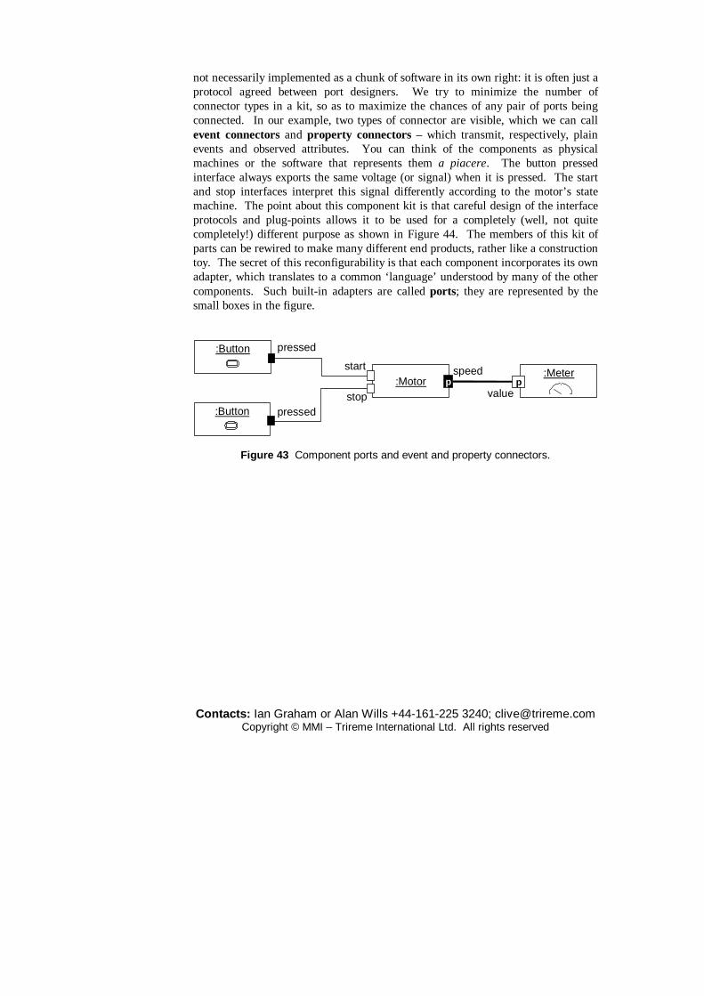
Contacts: Ian Graham or Alan Wills +44-161-225 3240; [email protected] Copyright © MMI – Trireme International Ltd. All rights reserved
not necessarily implemented as a chunk of software in its own right: it is often just a protocol agreed between port designers. We try to minimize the number of connector types in a kit, so as to maximize the chances of any pair of ports being connected. In our example, two types of connector are visible, which we can call event connectors and property connectors – which transmit, respectively, plain events and observed attributes. You can think of the components as physical machines or the software that represents them a piacere. The button pressed interface always exports the same voltage (or signal) when it is pressed. The start and stop interfaces interpret this signal differently according to the motor’s state machine. The point about this component kit is that careful design of the interface protocols and plug-points allows it to be used for a completely (well, not quite completely!) different purpose as shown in Figure 44. The members of this kit of parts can be rewired to make many different end products, rather like a construction toy. The secret of this reconfigurability is that each component incorporates its own adapter, which translates to a common ‘language’ understood by many of the other components. Such built-in adapters are called ports; they are represented by the small boxes in the figure.
start
pressed
pressedstop
:Motor
:Button
:Button
:Meterp
speed
valuep
Figure 43 Component ports and event and property connectors.

Contacts: Ian Graham or Alan Wills +44-161-225 3240; [email protected] Copyright © MMI – Trireme International Ltd. All rights reserved
pressed:Button
pressed:Button
start
stop
:Motor pspeed
:Metervalue
p:Threshold
p
pa<b
a>b
a
b
5:intp
:Selector{1,10,100}
p
:Multiplierp a×b
ppa ba
b
a∨ b:OR
Figure 44 Creating different products from the same components. The connector is such a useful abstraction that it deserves a notation in its own
right: we have used the UML-RT notation here (with some artistic licence to highlight our two types of connector). The objects in this notation are stereotyped «capsule». The small black squares in this example are output ports and the white ones input ports. A ‘p’ indicates a continuous ‘property’ port: these transmit values as often as necessary to keep the receiving end up to date with the sender – in other words, an observer. Unmarked ports transmit discrete events. Property connectors are shown by bolder lines than event connectors.
Once we have understood what the ports represent, we can get on and design useful products from kits of components, without bothering about all the details of registering interest, notification messages, and so on.
Ports can contain quite complex protocols. Each component must be well-specified enough to be usable without having to look inside it. So let’s consider one way a port might work, as shown in Figure 45. An output port provides messages that allow another object to register interest in the event it carries; when the relevant event occurs (for example, when the user touches a button component) the port sends a standard ‘notify’ message to all registered parties. An input port implements the LISTENER interface for these notify messages; when it receives one, it sends a suitable message into the body of its component. For example, the ‘start’ port of the Motor component, when it receives a standard notify( ) message, will pass start ( ) to the principal object representing the motor.
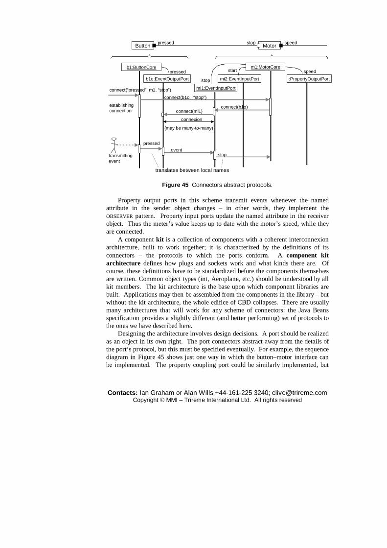
Contacts: Ian Graham or Alan Wills +44-161-225 3240; [email protected] Copyright © MMI – Trireme International Ltd. All rights reserved
b1:ButtonCore
b1o:EventOutputPort
pressedm1:MotorCore
mi2:EventInputPort
start
mi1:EventInputPort
stop :PropertyOutputPort
speed
connect(“pressed”, m1, “stop”)
connect(mi1)
connect(b1o, “stop”)
connect(b1o)
connexion
establishingconnection
(may be many-to-many)
pressedevent
stoptransmittingevent
translates between local names
Button Motorpressed stop speed
Figure 45 Connectors abstract protocols. Property output ports in this scheme transmit events whenever the named
attribute in the sender object changes – in other words, they implement the OBSERVER pattern. Property input ports update the named attribute in the receiver object. Thus the meter’s value keeps up to date with the motor’s speed, while they are connected.
A component kit is a collection of components with a coherent interconnexion architecture, built to work together; it is characterized by the definitions of its connectors – the protocols to which the ports conform. A component kit architecture defines how plugs and sockets work and what kinds there are. Of course, these definitions have to be standardized before the components themselves are written. Common object types (int, Aeroplane, etc.) should be understood by all kit members. The kit architecture is the base upon which component libraries are built. Applications may then be assembled from the components in the library – but without the kit architecture, the whole edifice of CBD collapses. There are usually many architectures that will work for any scheme of connectors: the Java Beans specification provides a slightly different (and better performing) set of protocols to the ones we have described here.
Designing the architecture involves design decisions. A port should be realized as an object in its own right. The port connectors abstract away from the details of the port’s protocol, but this must be specified eventually. For example, the sequence diagram in Figure 45 shows just one way in which the button–motor interface can be implemented. The property coupling port could be similarly implemented, but

Contacts: Ian Graham or Alan Wills +44-161-225 3240; [email protected] Copyright © MMI – Trireme International Ltd. All rights reserved
with regular update of new values. Although we have illustrated the principle of the connector with small
components, the same idea applies to large ones, in which the connector protocols are more complex and carry complex transactions. The current concern with Enterprise Application Integration can be seen as the effort to replace a multiplicity of point-to-point protocols with a smaller number of uniform connectors.
When specifying ports, or capsules, specify the types of parameters passed, the interaction protocol and the language in which the protocol is expressed. The interaction protocol could be any of:
� Ada rendezvous; � complex transaction; � asynchronous call; � continuous dataflow; � broadcast; � FTP; � buffered message; � function call; � call handover; � HTTP, and so on.
The interaction language could be:
� ASCII, etc.; � plain procedure call; � CORBA message or event; � RS232; � DLL/COM call; � TCP/IP; � HTML; � UNIX pipe; � Java RMI; � XML; � Java serialized; � zipped.
7 Designing components
Writing in Byte John Udell tells us that ‘Objects are dead!’ and will be replaced by components. But he wrote this in May 1994, whereas objects didn’t really hit the mainstream of information technology until around 1996/7. In fact, most CBD offerings that were around in 1994 didn’t survive for very long after that: think of OpenDoc, OpenStep, Hyperdesk, etc. Probably the only significant survivor was the humble VBX. Currently, there are several understandings of what the term ‘component’ means. Some commentators just use it to mean any module. Others mean a deliverable object or framework: a unit of deployment. Still others mean a binary that can create instances (of multiple classes). Writers on object-oriented analysis tend to mean a set of interfaces with offers and requires constraints. The requires constraints are often called outbound interfaces. Daniels (2000) questions this and shows that while these aspects of a component must be defined, they do not form part of the component’s contract. Szyperski (1998) defines a component as ‘a binary unit of independent production, acquisition and deployment’ and later ‘A unit of composition with contractually specified interfaces and explicit context

Contacts: Ian Graham or Alan Wills +44-161-225 3240; [email protected] Copyright © MMI – Trireme International Ltd. All rights reserved
dependencies only’. We prefer: a unit of executable deployment that plays a part in a composition.
In many ways, VB is still the paradigm for component-based development. Components were needed initially because OOPLs were restricted to one address space. Objects compiled by different compilers (even in the same language) could not communicate with each other. Thus arose distribution technologies such as RPCs, DCOM, CORBA, and so on. In every case interfaces were defined separately from implementation, making OOP only one option for the actual coding of the objects.
In the late 1990s ERP vendors that surfed on the crest of the year 2000 and Euro conversion issues did well because their customers needed quick, all-embracing solutions. When that period ended their market was threatened by a return to more flexible systems that were better tailored to companies’ requirements. One vendor was even quoted as saying that a large customer should change its processes to fit the package because the way they worked was not ‘industry standard’. This arrogance would no longer be tolerable after 2000 and the vendors were seen to rush headlong to ‘componentize’ their offerings; i.e. introduce greater customizability into them.
A lot of the talk about components being different from (better than) objects was based on a flawed idea of what a business object was in the first place. Many developers assumed that the concept of an object was coextensive with the semantics of a C++ class or instance. Others based their understanding on the semantics of Smalltalk objects or Eiffel classes or instances. Even those who used UML classes or instances failed to supply enough semantic richness to the concept: typically ignoring the presence of rules and invariants and not thinking of packages as wrappers. Furthermore, an object will only work if all its required services (servers) are present. This was the standpoint of methods such as SOMA from as early as 1993. SOMA always allowed message-server pairs as part of class specifications. These are equivalent to what Microsoft COM terminology calls outbound interfaces.
From one point of view, outbound interfaces violate encapsulation, because the component depends on collaborators that may change and so affect it. For example, the client of an order management service should not have to know that this component depends on a product management one; an alternative implementation might bundle everything up into one object. For this reason John Daniels (2000) argues that collaborations do not form part of an object’s contract in the normal sense. He distinguishes usage contracts from implementation contracts. The latter do include dependencies, as they must to be of use to the application assembler. That more research is needed in this area is revealed by one of Daniels’ own examples. Consider a financial trading system that collaborates with a real-time price feed. The user of the system should not care, on the above argument, whether the feed is provided by a well-known and reputable firm, such as Reuters, or by Price, Floggett & Runne Inc. But of course the user cares deeply about the

Contacts: Ian Graham or Alan Wills +44-161-225 3240; [email protected] Copyright © MMI – Trireme International Ltd. All rights reserved
reliability of the information and would differentiate sharply between these two suppliers. This example suggests that we should always capture the effects of collaborations as invariants or rulesets in the usage contracts, if not the collaborators themselves. The rules in this case would amount to a statement about the reputability of the information provider.
Current component-based development offerings include CORBA/OMA, Java Beans/EJB, COM/DCOM/ActiveX/COM+, TI Composer and the more academically based Component Pascal/Oberon. What these approaches all have in common is an emphasis on composition/forwarding, compound documents, transfer protocols (e.g. JAR files), event connectors (single or multi-cast), metadata and some persistence mechanism. Differentiators between the approaches include their approaches to interface versioning, memory management, adherence to standards (binary/binding/etc.), language dependence and platform support.
From a supplier’s point of view components are usually larger than classes and may be implemented in multiple languages. They can include their own metadata and be assembled without programming (!). They need to specify what they require to run. These statements could almost be a specification for COM+ or CORBA. Such component systems are not invulnerable to criticism. The size of a component is often inversely proportional to its match to any given requirement. Also, components may have to be tested late; an extreme case being things that cannot be tested until the users downloads them (although applets are not really components in the sense we mean here). There is a tension between architectural standards and requirements, which can limit the options for business process change. Finally there is the problem of shared understanding between developers and users. Szyperski discusses at length the different decision criteria used by each of infrastructure vendors and component vendors. He says nothing about the consequences for users. Can we deduce that users don’t care about how components are developed? They certainly care about how they are assembled into applications.
Object modelling is about not separating processes from data. It is about encapsulation: separating interfaces from implementation. It is about polymorphism: inheritance and pluggability. It is about design by contract: constraints and rules. OO principles must be consistently applied to object-oriented programming, object-oriented analysis, business process modelling, distributed object design and components. However, there is a difference between conceptual models and programming models. In conceptual modelling both components and classes have identity. Therefore components are objects. Inheritance is as fundamental as encapsulation for the conceptual modeller. In programming models on the other hand components and classes do not have identity (class methods are handled by instances of factory classes). Thus components are not objects, class inheritance (or delegation) is dangerous and pluggability is the thing. So is there a rôle for inheritance? CBD plays down ‘implementation inheritance’ but not interface inheritance, but at the conceptual level this distinction makes no sense anyway.

Contacts: Ian Graham or Alan Wills +44-161-225 3240; [email protected] Copyright © MMI – Trireme International Ltd. All rights reserved
When it comes to linking requirements models to analysis models, we can either ‘dumb down’ to a model that looks like the programming model (as most UML-based methods tend to do) or introduce a translation process between the models. The trade-off concerns the degree to which users and developers can share a common understanding.
7.1 Components for flexibility
Component-based development is concerned with building extensible families of software products from new or existing kits of components. The latter may range in scale from individual classes to entire (wrapped) legacy systems or commercial packages. Doing this has hitherto proved an elusive goal for software developers. The trick is to realize that we need to define the interface protocols of objects in such a way that they can be plugged together in different ways. The number of interfaces needs to be small compared to the number of components. To improve flexibility these interfaces should permit negotiation in the same way as with facsimile machines or clipboard interfaces in Microsoft’s OLE and the like.
Hotel support system
French staff payer
Management XmasBonus Payer
Staff paymentinterface
Least-recently-usedRoom Allocator
Nearest-front-deskRoom Allocator
Room allocationinterface
UK staff payer
German staff payer
messages
Figure 46 Plug-points add flexibility. An example may suffice to explain the point. Consider an hotel support system
that is originally written for a small chain of Scottish hotels. The original is a great success and pays for itself quickly. But the price of success is rapid expansion and the company now acquires several more hotels in England, Wales, France and Germany. In Scotland rooms are always allocated to new arrivals on the basis of the empty room nearest the reception desk – to save visitors wearing out their shoes walking long distances. But the spendthrift and gloomy English want peace and

Contacts: Ian Graham or Alan Wills +44-161-225 3240; [email protected] Copyright © MMI – Trireme International Ltd. All rights reserved
quiet more than these savings; so that rooms are allocated alternately, to leave empty rooms separating occupied ones when the hotel is not full. The Germans allocate rooms with French widows first. The different states involved also have different rules about wage payments. The system is amended piecemeal and soon there are several versions to maintain: one with nearest desk allocation and French payment rules, another with least-recently-used room allocation and UK staff payment laws and an ad hoc patch for management christmas bonuses in Ireland and the Netherlands, and so on. A maintenance disaster of some proportion!
A considerable improvement on arbitrary modification is shown in Figure 46. There is a basic framework, which does everything that is common between the requirements of all the hotels. Each separate variable requirement has been moved into a plug-in component: for example, there are different room-allocators; and different staff payment components. This arrangement makes it much easier to maintain and manage variants of the system. We separate the rôles of the framework-designer and the designers of the plug-in components – who are not allowed to change the framework.
This makes it very clear that the most suitable basis for choosing components is that they should correspond to variable requirements. This is a key rule which people sometimes forget, while still claiming to be doing component-based development.
One problem is that it is not always easy to foresee what requirements will be variable in the future. The best advice we can give here is as follows.
� Follow the principle of separation of concerns within the main framework, so that it is reasonably easy to refactor.
� Don’t cater for generalizations that you don’t know you are going to need: the work will likely be wasted. Observe the eXtreme Programming maxim: ‘You ain’t gonna need it!’.
� Where you do need to refactor the framework to introduce new plug-points, make one change at a time, and re-test after each change.
7.2 Large-scale connectors
In the previous section, we introduced the idea of connectors, using a Bean-scale example to illustrate the principle; the connectors transmitted simple events and property-values. But we can also use the same idea where the components are large applications running their own databases and interoperating over the internet. Recall that the big advantage of connectors over point-to-point interfaces was that we try to design a small number of protocols common to the whole network of components, so that they can easily be rearranged. In our small examples, that meant that we could pull components out of a bag and make many end-products; for large systems, it means that you can more easily rearrange the components as the business changes. This is a common problem being faced by many large and not-
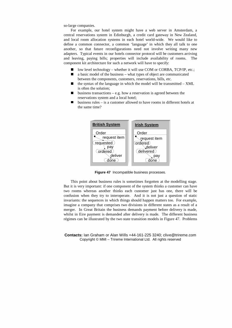
Contacts: Ian Graham or Alan Wills +44-161-225 3240; [email protected] Copyright © MMI – Trireme International Ltd. All rights reserved
so-large companies. For example, our hotel system might have a web server in Amsterdam, a
central reservations system in Edinburgh, a credit card gateway in New Zealand, and local room allocation systems in each hotel world-wide. We would like to define a common connector, a common ‘language’ in which they all talk to one another, so that future reconfigurations need not involve writing many new adapters. Typical events in our hotels connector protocol will be customers arriving and leaving, paying bills; properties will include availability of rooms. The component kit architecture for such a network will have to specify:
� low level technology – whether it will use COM or CORBA, TCP/IP, etc.; � a basic model of the business – what types of object are communicated
between the components, customers, reservations, bills, etc. � the syntax of the language in which the model will be transmitted – XML
is often the solution; � business transactions – e.g. how a reservation is agreed between the
reservations system and a local hotel; � business rules – is a customer allowed to have rooms in different hotels at
the same time?
Irish System
Order
ordered
delivered
done
request item
deliver
pay
British System
Order
requested
ordered
done
request item
pay
deliver
Figure 47 Incompatible business processes.
This point about business rules is sometimes forgotten at the modelling stage. But it is very important: if one component of the system thinks a customer can have two rooms whereas another thinks each customer just has one, there will be confusion when they try to interoperate. And it is not just a question of static invariants: the sequences in which things should happen matters too. For example, imagine a company that comprises two divisions in different states as a result of a merger. In Great Britain the business demands payment before delivery is made, whilst in Eire payment is demanded after delivery is made. The different business régimes can be illustrated by the two state transition models in Figure 47. Problems
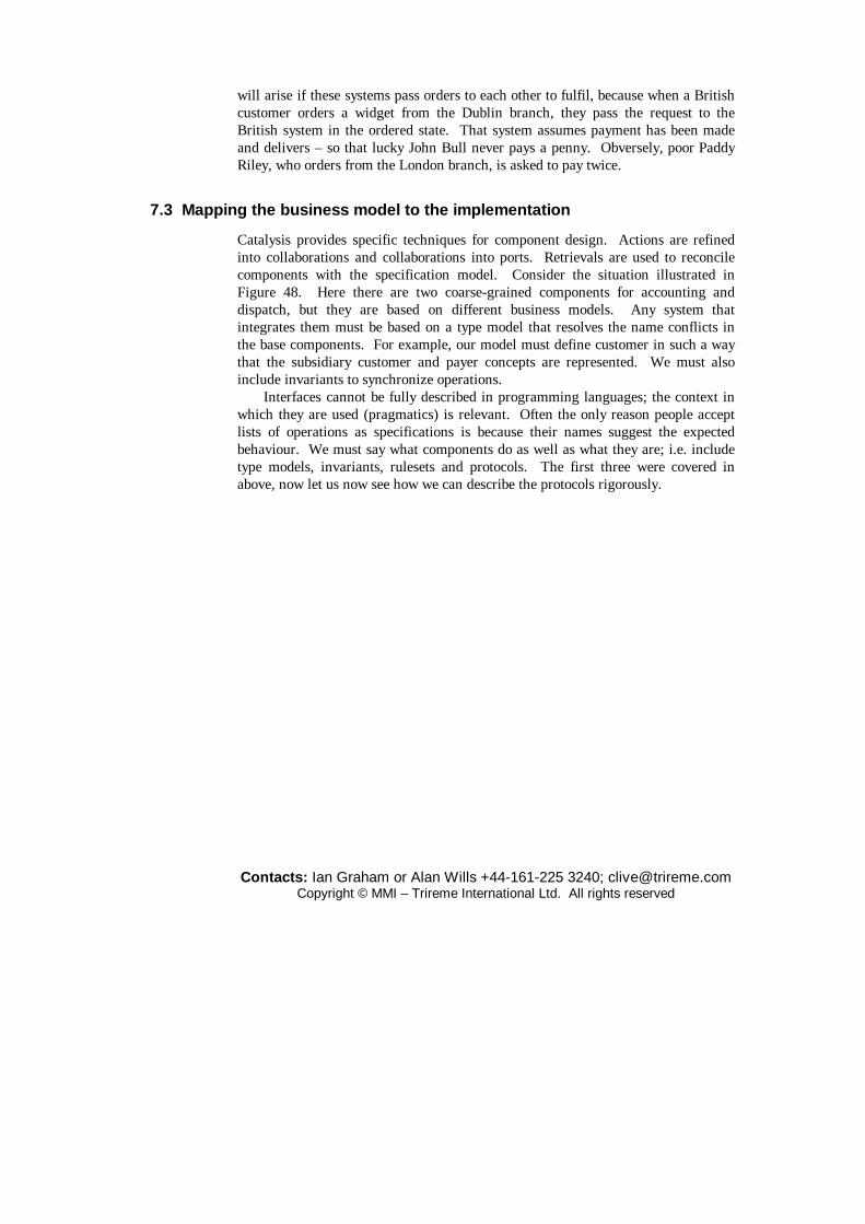
Contacts: Ian Graham or Alan Wills +44-161-225 3240; [email protected] Copyright © MMI – Trireme International Ltd. All rights reserved
will arise if these systems pass orders to each other to fulfil, because when a British customer orders a widget from the Dublin branch, they pass the request to the British system in the ordered state. That system assumes payment has been made and delivers – so that lucky John Bull never pays a penny. Obversely, poor Paddy Riley, who orders from the London branch, is asked to pay twice.
7.3 Mapping the business model to the implementation
Catalysis provides specific techniques for component design. Actions are refined into collaborations and collaborations into ports. Retrievals are used to reconcile components with the specification model. Consider the situation illustrated in Figure 48. Here there are two coarse-grained components for accounting and dispatch, but they are based on different business models. Any system that integrates them must be based on a type model that resolves the name conflicts in the base components. For example, our model must define customer in such a way that the subsidiary customer and payer concepts are represented. We must also include invariants to synchronize operations.
Interfaces cannot be fully described in programming languages; the context in which they are used (pragmatics) is relevant. Often the only reason people accept lists of operations as specifications is because their names suggest the expected behaviour. We must say what components do as well as what they are; i.e. include type models, invariants, rulesets and protocols. The first three were covered in above, now let us now see how we can describe the protocols rigorously.

Contacts: Ian Graham or Alan Wills +44-161-225 3240; [email protected] Copyright © MMI – Trireme International Ltd. All rights reserved
dispSysaccSys
Customername
OrderItemvalue*
Dispatch System
*
* order
customers
Account
Payername
Accounts System
Itemcode
value: £*
*
1 ac
payers
Business Support System
Customername
Order OrderItemvalue: £
AcctItemvalue: £Account
1
*
*
**
OrderTotal
11 inv OrderTotal ::
value==order.items.value->sum
BusSprtSysRetrieval
retrieval
synch invariant
retrieval
cross-reference1
0,1
0,11 cross-referenceacctItem
payer
Figure 48 Retrieving a model from components. Just as connectors must be encapsulated in objects, they can also be specialized
and generalized. Templates, or frameworks, are used to define connector classes. We define and specify each class and its interfaces. Next the connector classes are defined. Then message protocols for each class of connector can be defined using sequence and/or state diagrams. We must always ensure that a business model, common to all components, is clearly defined using a type model rich enough to define all parameters of the connector protocols. Points of potential variation should be handled using plug-points. Business rules should be encapsulated by the interfaces.
Components will be used in contexts unknown to their designer(s) and so need far better ‘packaging’ than simple, fine-grain classes in class libraries. They should be stored and delivered with full documentation, covering the full specification and all the interfaces and ports and their protocols. It is mandatory that components should be supplied therefore with their test harnesses. Good component architectures require that components should be able to answer queries about their connexions at run time: complaining rather than collapsing under abuse by other software.

Contacts: Ian Graham or Alan Wills +44-161-225 3240; [email protected] Copyright © MMI – Trireme International Ltd. All rights reserved
8 Notation summary
8.1 Object modelling symbols
start: Point
end: Point
p8/start,end: Point
x = 3y = 3.1416
rôlenames
collaboration typesrôles
p17: Point
instances
Figure 8.1 Instances, rôles and collaborations.
Book
This is a type too:drawn in its shortform.
BookTitlenameauthor: Person(0,*)publisherRRP: Money(0,1)
number-in-stock
This is a notesaying that whatit points to is a typeor class.
operations
attributes &associations
named compartmentrulesetsrecommendation rules
List
n:type
generic type
note
Figure 8.2 Classes and types.

Contacts: Ian Graham or Alan Wills +44-161-225 3240; [email protected] Copyright © MMI – Trireme International Ltd. All rights reserved
Figure 8.3 Dependency symbols.
association
generalization
realization
dependency«label»
pkgnamesubsystem
interface
dependencypackage
Figure 8.4 Packages and subsystems.
CustomerBranchBank
Account
hqbranches 1
0..*holder 1,2
1..*
11..*
types
rôlename
cardinality
association
Figure 8.5 Associations.
Directory file name File0..*
Figure 8.6 Qualifiers.

Contacts: Ian Graham or Alan Wills +44-161-225 3240; [email protected] Copyright © MMI – Trireme International Ltd. All rights reserved
Person Committee
* *
*1
Member-of
President-of
{subset}
{Committee.president-of.age>16}
Figure 8.7 Unencapsulated constraints. Some constraints are pre-defined in UML, such as {ordered} and {or} – see Figure 6.7(a).
dataset«entity»
interface«boundary»
controller«controller»
Figure 8.8 Visual stereotypes for classes.
Contacts: Ian Graham or Alan Wills +44-161-225 3240; [email protected] Copyright © MMI – Trireme International Ltd. All rights reserved
Bank_account
Current_account Deposit_account
Interest bearingcurrent accounts
Bank accounts
Mortgageaccounts
Depositaccounts
Currentaccounts
generalization
realization
Current_accountsinstantiation
myAccount: Current_accounts«isa»
Figure 8.9 Inheritance.
Type1 Type2
AssociationType
Figure 8.10 Association types.

Contacts: Ian Graham or Alan Wills +44-161-225 3240; [email protected] Copyright © MMI – Trireme International Ltd. All rights reserved
List
Head
Rectangle
Point
Editor
Shape Library
composition aggregation containment
1..*1..1
Figure 8.11 Aggregation.
Type BType C
Type A2
Type A1
Type A
Type B2Type B1
Figure 8.12 Derived dependencies.
+ public – private # protected
Figure 8.13 Visibility symbols for packages and class features.

Contacts: Ian Graham or Alan Wills +44-161-225 3240; [email protected] Copyright © MMI – Trireme International Ltd. All rights reserved
8.2 Action (use case) modelling symbols
salePurchaser
use-case
actor
system boundary
sale
Figure 8.14 Actors and use cases. The dependencies of Figure C.3 may also connect use case icons.
8.3 Sequence and collaboration diagram symbols
ian: Person
pat: Manager
chris: Secretary
intray: WorkTray
1.2 *acceptApplication(ianApplic)
1.2.1 put(ianApplic) 2 needWorker()
ianApplic: Application
2.1 nextApplicn()
2.1.1 get()
1 needJob( )“*” = repeated with other receiver instances
1.1 new
boss
1 intrayinstance creation
messageassociation
Figure 8.15 Collaboration diagram notation.
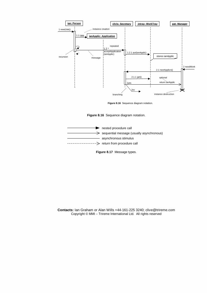
Contacts: Ian Graham or Alan Wills +44-161-225 3240; [email protected] Copyright © MMI – Trireme International Ltd. All rights reserved
Figure 8.16 Sequence diagram notation.
pat: Managerchris: Secretary intray: WorkTray
1.2 *acceptApplication(ianApplic)
1.2.1 put(ianApplic)
ianApplic: Application
2.1 nextApplicn()
2.1.1 get()
1.1 new
instance creation
message
1 needJob()
2 needWork
return ianApplic
optional
ian: Person
stores ianApplic
repeated
instance destruction
recursion
[yes
[no
branching
Figure 8.16 Sequence diagram notation.
nested procedure call
sequential message (usually asynchronous)
asynchronous stimulus
return from procedure call
Figure 8.17 Message types.

Contacts: Ian Graham or Alan Wills +44-161-225 3240; [email protected] Copyright © MMI – Trireme International Ltd. All rights reserved
8.4 State modelling symbols
StateAdo/ activityN
StateDdo/ activityP
(attrib1:Type,attrib2:Type)[guard]/action1;action2;...event
Normal Menuvisible
Mousedown(right)/display popup
Mouseup(right)/hide popup
Mouseover/HighlightMenuItem
start state
end state
H
H*
history state
deep history state
junction state
Figure 8.18 State chart notation.
nested states
superstate
substate1
substate2
event1
event3
event2
event1
concurrent states
superstate
substate1
substate2
substate3
substate4
event2
Figure 8.19 Nested and concurrent states.

Contacts: Ian Graham or Alan Wills +44-161-225 3240; [email protected] Copyright © MMI – Trireme International Ltd. All rights reserved
substate2 substate4
substate3substate1 event1
event2
event0event3
event4
process
Figure C.20 Concurrent event bifurcation and synchronization.
idle
remote ringing
engageddial number[target busy]
dial number[target idle]
Figure C.21 Guarded transitions.

Contacts: Ian Graham or Alan Wills +44-161-225 3240; [email protected] Copyright © MMI – Trireme International Ltd. All rights reserved
8.5 Action or activity diagram symbols
Prepareorder
Assign itemto delivery
Assign goodsto warehouse
Pick deliveryto satisfy order
Assign stockto delivery
Order prepared
Order satisfied?Y
N &priorityorder
Mark orderas satisfied
Reorderstock
Y
Reorderneeded?
Goodsarrive
Neworder
Allorders
satisfied
Deliveryto pick?
YN
Goodsremaining?
Y
SALES GOODS INWARD
swimlanes
Figure C.22 Action/activity diagrams.

Contacts: Ian Graham or Alan Wills +44-161-225 3240; [email protected] Copyright © MMI – Trireme International Ltd. All rights reserved
8.6 Implementation and component modelling symbols
AdminServer:HostMachine
PC:MyMachine
:Planner
:SchedulerIreservations
«database»meetingsDB
«connexion type» «uses»
component instance
Realizationof interface
node instance
interface
Figure C.23 Nodes and interfaces.
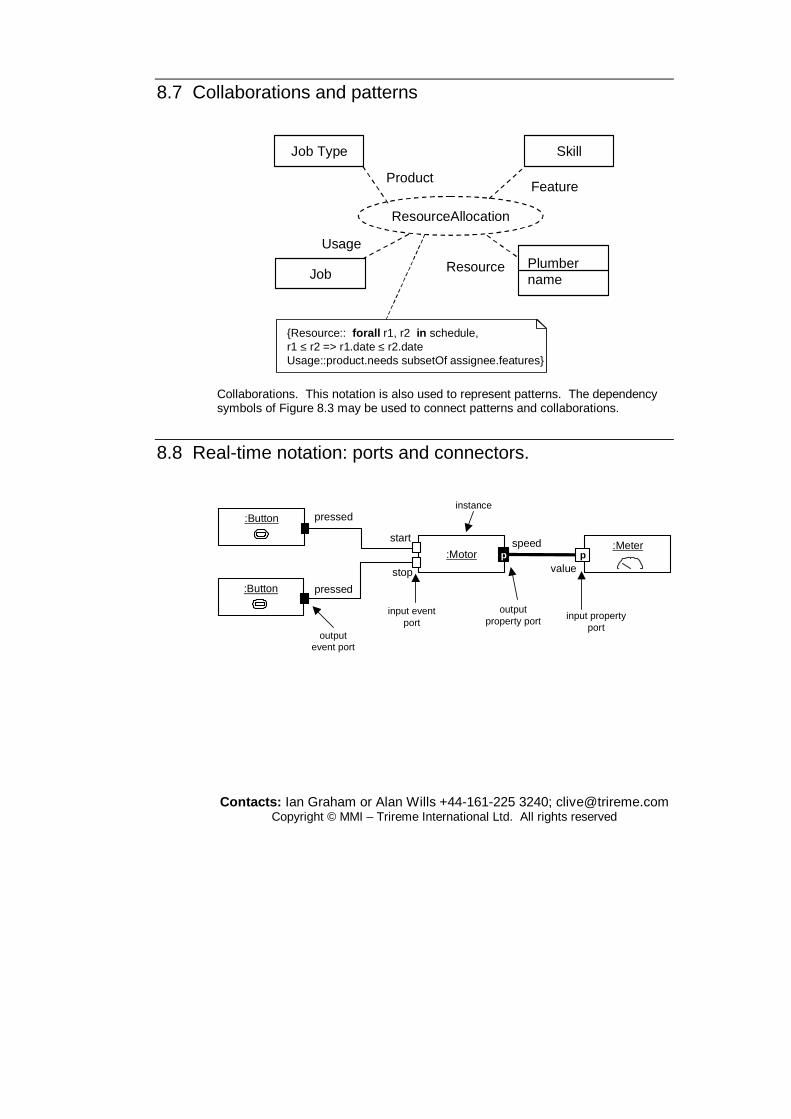
Contacts: Ian Graham or Alan Wills +44-161-225 3240; [email protected] Copyright © MMI – Trireme International Ltd. All rights reserved
8.7 Collaborations and patterns
Job Type
Job
Skill
Plumbername
ResourceAllocation
Product
Usage
Resource
Feature
{Resource:: forall r1, r2 in schedule, r1 ≤ r2 => r1.date ≤ r2.dateUsage::product.needs subsetOf assignee.features}
Collaborations. This notation is also used to represent patterns. The dependency symbols of Figure 8.3 may be used to connect patterns and collaborations.
8.8 Real-time notation: ports and connectors.
start
pressed
pressed
stop
:Motor
:Button
:Button
:Meterp
speed
valuep
instance
input eventport
outputevent port
outputproperty port input property
port

Contacts: Ian Graham or Alan Wills +44-161-225 3240; [email protected] Copyright © MMI – Trireme International Ltd. All rights reserved
9 Further reading
The treatment of object-oriented analysis and design in this tutorial has been mostly based on a synthesis of the insights of Catalysis and SOMA and the UML standard. These insights, of course, are in themselves derivative of the work of many other methodologists.
D’Souza and Wills (1999) defined Catalysis as a method for object-oriented and component-based development that made sense out of UML for the first time. The notion of rely and guarantee clauses comes from Cliff Jones’ (1986) work on VDM.
SOMA (The Semantic Object Modelling Approach) arose out of attempts to combine object-oriented analysis with ideas from business process modelling and knowledge-based systems (Graham, 1991, 1995, 1998).
A good, concise, popular summary of UML is (Fowler, 1997) with (Booch et al., 1999) and (Rumbaugh et al., 1999) being the original definitive references. The most current definitive reference will be found at www.omg.org.
Design patterns were introduced by Gamma et al. (1995). Buschmann et al. (1996) cover these together with architectural patterns. Pree (1995) is another early contribution in this area and introduced the idea of metapatterns. Fowler (1996) discusses analysis patterns, the idea of which was earlier suggested by Coad (1992). The annual proceedings of the PLoP conferences (Coplien and Schmidt, 1995; Vlissides et al., 1996) are full of interesting exegesis and new patterns including the earliest work on organizational patterns (Coplien, 1995). Beck (1997) is an excellent exposition of how to use patterns in the context of Smalltalk, well worth reading by those not interested in that language. Coplien (1992) describes C++ idioms. Mowbray and Malveau (1997) discuss patterns for CORBA implementations. Much current work on patterns has been inspired by the work of Christopher Alexander and his colleagues (1964, 1977, 1979) in the built environment. Richard Gabriel (1996) also provides much insight into the relevance of Alexander’s ideas.
Gardner et al. (1998) discuss their idea of cognitive patterns based on the task templates of the Common KADS knowledge engineering method. The idea is that common problem solving strategies, such as diagnosis, planning and product selection, can be classified as patterns that show how each kind of inference proceeds.
Brown et al. (1998) discuss anti-patterns: common solutions to frequently occurring problems that don’t work – and provide suggested solutions. The idea has much in common with the ‘software ailments’ of Capers Jones (1994).
OORAM (Reenskaug et al., 1996) was an influential method, tool and language in which collaborations and their composition were the central design mechanisms.
Cheesman and Daniels (2000) describe a simple process for specifying software
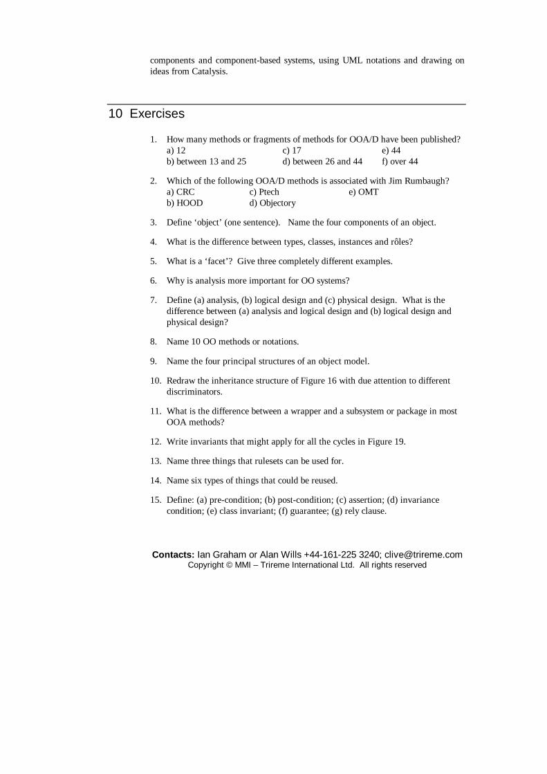
Contacts: Ian Graham or Alan Wills +44-161-225 3240; [email protected] Copyright © MMI – Trireme International Ltd. All rights reserved
components and component-based systems, using UML notations and drawing on ideas from Catalysis.
10 Exercises
1. How many methods or fragments of methods for OOA/D have been published? a) 12 c) 17 e) 44 b) between 13 and 25 d) between 26 and 44 f) over 44
2. Which of the following OOA/D methods is associated with Jim Rumbaugh? a) CRC c) Ptech e) OMT b) HOOD d) Objectory
3. Define ‘object’ (one sentence). Name the four components of an object.
4. What is the difference between types, classes, instances and rôles?
5. What is a ‘facet’? Give three completely different examples.
6. Why is analysis more important for OO systems?
7. Define (a) analysis, (b) logical design and (c) physical design. What is the difference between (a) analysis and logical design and (b) logical design and physical design?
8. Name 10 OO methods or notations.
9. Name the four principal structures of an object model.
10. Redraw the inheritance structure of Figure 16 with due attention to different discriminators.
11. What is the difference between a wrapper and a subsystem or package in most OOA methods?
12. Write invariants that might apply for all the cycles in Figure 19.
13. Name three things that rulesets can be used for.
14. Name six types of things that could be reused.
15. Define: (a) pre-condition; (b) post-condition; (c) assertion; (d) invariance condition; (e) class invariant; (f) guarantee; (g) rely clause.

Contacts: Ian Graham or Alan Wills +44-161-225 3240; [email protected] Copyright © MMI – Trireme International Ltd. All rights reserved
16. Compare three OO methods known to you.
17. How do you decide whether something is to be modelled as an attribute or a class?
18. Bi-directional associations violate encapsulation. Why? How can this problem be easily overcome? Is this true in analysis as well as design? If not, why not?
19. Discuss the use of normalization in object-oriented and conventional modelling.
20. Discuss the use of functional decomposition in object-oriented and conventional modelling.
21. Write a small ruleset to describe the behaviour of a technical analyst (chartist) dealing in a single security.
22. When should state models be used and what for?
23. Give an example of a question that might elicit an abstract class from two more concrete classes. Give an example of a question that might elicit more concrete classes from a list of objects. Give an example of a question that might elicit a yet unmentioned concept.
24. Give some simple guidelines for textual analysis.
25. ‘A type’s existence is independent of the existence of its instances.’ Discuss, with reference to Plato.
26. Why is analysis important for OO programmers?
27. Does God throw exceptions?
28. Using the approach described in this tutorial specify either: a) a simple public library lending administration system, where books can be borrowed, reserved and returned; or b) a simple drawing tool, where shapes can be drawn, moved, deleted and grouped.
29. Compare two architectural styles from the following list: layers, blackboard, pipes and filters, CORBA, peer-to-peer, client-server.
30. Define what you understand by software architecture. Why is architecture not merely high level structure?

Contacts: Ian Graham or Alan Wills +44-161-225 3240; [email protected] Copyright © MMI – Trireme International Ltd. All rights reserved
31. Define the terms: pattern, design pattern, analysis pattern, organizational pattern architectural pattern. Give examples of each.
32. Distinguish between a patterns catalogue and a pattern language, giving examples.
33. Write a pattern in Alexandrian form showing how to decouple the various shapes that could be drawn in a drawing editor from the core editor. In doing this, consider the problems of how to ‘smooth’ and ‘unsmooth’ polygons and increase or decrease the number of their vertices in a sensible way.
34. Write patterns to deal with the following situations: a) the need to inform all users of e-mail of a change to their e-mail addresses, when some may be on holiday; b) users in a workshops continually disagree with each other; c) management resist object technology because they consider it too risky.
35. Discuss the pros and cons of inheritance versus delegation.
36. Discuss the differences between Catalysis and another OO method known to you with respect to component-based development.
37. What is a retrieval? Give an example.
38. Mini project Produce a framework template for school timetable preparation: allocating suitable classrooms, qualified teachers, ten subjects and five one-hour time-slots per weekday. Include all invariants; e.g. Chemistry needs a classroom with sinks and there must be at least five hours of Maths and English per week. Are there any rules that are hard to express in OCL? Why is this? Apply the same framework to factory production scheduling.
Related Documents