UMB Protocol 1.0 IRS31-UMB Universal Measurement Bus VS20-UMB Communication Protocol R2S-UMB for Meteorological Sensors WS200-UMB WS300-UMB WS400-UMB WS500-UMB WS600-UMB ANACON-UMB IRS21CON-UMB LCOM NIRS31-UMB Status 17.12.2010 Protocol Version 1.0 Document Version 1.6

Welcome message from author
This document is posted to help you gain knowledge. Please leave a comment to let me know what you think about it! Share it to your friends and learn new things together.
Transcript
UMB Protocol 1.0 IRS31-UMB
Universal Measurement Bus VS20-UMB
Communication Protocol R2S-UMB
for Meteorological Sensors WS200-UMB
WS300-UMB
WS400-UMB
WS500-UMB
WS600-UMB
ANACON-UMB
IRS21CON-UMB
LCOM
NIRS31-UMB
Status 17.12.2010
Protocol Version 1.0
Document Version 1.6
2
File: UMB-Protokoll 1_0 Version 1_6_e.docx, Version 1.6, Status 17.12.2010
Table of Contents 1 Version History ............................................................................................................. 4
2 Preliminary Remarks .................................................................................................... 6
2.1 Restricted Guarantee .............................................................................................. 6 2.2 Nomenclature .......................................................................................................... 6 2.3 Data Format and Byte Order in the Communication Protocol: ................................. 6 2.4 Physical Connection and Hardware Structure ......................................................... 6 2.5 Software Protocol .................................................................................................... 6 2.6 Products .................................................................................................................. 7
3 UMB Binary Protocol (Version 1.0) ............................................................................. 8 3.1 Protocol Stack (Framing) ......................................................................................... 8
3.1.1 Application Layer .............................................................................................. 8 3.1.2 Presentation Layer/Session Layer/Transport Layer .......................................... 8 3.1.3 Network Layer .................................................................................................. 8 3.1.4 Data Link Layer ................................................................................................ 8 3.1.5 Physical Layer .................................................................................................. 9 3.1.6 Timing Sensor .................................................................................................. 9 3.1.7 Timing Master .................................................................................................. 9 3.1.8 Summary .........................................................................................................10
3.2 Topology ................................................................................................................11 3.3 Addressing with Class and Device ID .....................................................................12
3.3.1 Examples for the Creation of Addresses .........................................................12 3.4 CRC Checksum .....................................................................................................12 3.5 Commands (Datagrams) ........................................................................................13
3.5.1 Summary of Commands ..................................................................................13 3.5.2 Hardware and Software Version (20h) ............................................................14 3.5.3 Device Information (2Dh) ................................................................................14 3.5.4 Read Out EEPROM (21h) ...............................................................................15 3.5.5 Programme EEPROM (22h) ............................................................................15 3.5.6 Programme EEPROM with PIN (F0h) .............................................................15 3.5.7 Online Data Request (23h) ..............................................................................16 3.5.8 Multi-Channel Online Data Request (2Fh) .......................................................16 3.5.9 Offline Data Request (24h) ..............................................................................17 3.5.10 Reset / Default (25h) .......................................................................................17 3.5.11 Reset with Delay (2Eh) ....................................................................................17 3.5.12 Status Request (26h) ......................................................................................17 3.5.13 Last Error Message (2Ch) ...............................................................................17 3.5.14 Set Time / Date (27h) ......................................................................................18 3.5.15 Readout Time / Date (28h) ..............................................................................18 3.5.16 Test / Calibration Command (29h) ...................................................................18 3.5.17 Monitor (2Ah) ..................................................................................................18 3.5.18 Protocol Change (2Bh) ....................................................................................19 3.5.19 Set New Device ID (30h) .................................................................................19
3.6 Status and Error Codes ..........................................................................................20 3.7 Data Types .............................................................................................................22 3.8 Measurement Value Types .....................................................................................22 3.9 Channel Assignment ..............................................................................................23
3.9.1 Channel Assignment – General Allocation ......................................................23 3.9.2 Channel Assignment Device Class 1 Road Sensor .........................................24 3.9.3 Channel Assignment Device Class 2 Rain Sensor ..........................................25 3.9.4 Channel Assignment Device Class 3 Visibility Sensor .....................................26
3
File: UMB-Protokoll 1_0 Version 1_6_e.docx, Version 1.6, Status 17.12.2010
3.9.5 Channel Assignment Device Class 4 Active road sensor ................................27 3.9.6 Channel Assignment Device Class 5 Non invasive road sensor ......................28 3.9.7 Channel Assignment Device Class 6 Universal Measurement Transmitter ......29 3.9.8 Channel Assignment Device Class 7 Compact Weather Station .....................30 3.9.9 TLS Channel Assignment ................................................................................31
3.10 Units List ................................................................................................................31 3.10.1 Temperature ...................................................................................................31 3.10.2 Humidity ..........................................................................................................31 3.10.3 Lengths ...........................................................................................................31 3.10.4 Velocities .........................................................................................................31 3.10.5 Electrical Variables ..........................................................................................32 3.10.6 Frequency .......................................................................................................32 3.10.7 Pressure ..........................................................................................................32 3.10.8 Volumes ..........................................................................................................32 3.10.9 Time ................................................................................................................32 3.10.10 Miscellaneous ..............................................................................................32
3.11 Example of a Binary Protocol Request ...................................................................33 3.12 Comments about Broadcast ...................................................................................34
4 UMB ASCII Protocol ....................................................................................................35
4.1 Construction ...........................................................................................................35 4.1.1 Summary of the ASCII Commands ..................................................................35 4.1.2 Online Data Request (M) .................................................................................35 4.1.3 Protocol Change (X) ........................................................................................36 4.1.4 Reset / Default (R) ..........................................................................................36 4.1.5 Reset with Delay (D) .......................................................................................36 4.1.6 Device Information (I) ......................................................................................36
4.2 Error Codes in the ASCII Protocol ..........................................................................37
5 Appendix ......................................................................................................................38
5.1 CRC Calculation .....................................................................................................38 5.1.1 Example of a CRC-CCITT Calculation in C .....................................................38
5.2 Automatic Readout of a Network ............................................................................40 5.2.1 Background .....................................................................................................40 5.2.2 Necessary ID Configuration of the Sensors .....................................................40 5.2.3 Scanning the Network .....................................................................................40
5.3 Data Types in UMB Products per TLS2002 FG3 ....................................................41 5.3.1 Example of a TLS Measurement Value Request .............................................41 5.3.2 Supported TLS-DE Types FG3 .......................................................................42 5.3.3 DE Type 70 “Road Surface Condition” (RSC)..................................................46 5.3.4 DE Type 71 “Precipitation Type” (PT) ..............................................................47 5.3.5 DE Type 140 “Door Contact” (DC) ...................................................................48 5.3.6 DE Type 140 Inverted “Door Contact” (DC) .....................................................48
5.4 Character Table for Text Editions ...........................................................................49 5.5 Recording of a binary request ................................................................................50
4
File: UMB-Protokoll 1_0 Version 1_6_e.docx, Version 1.6, Status 17.12.2010
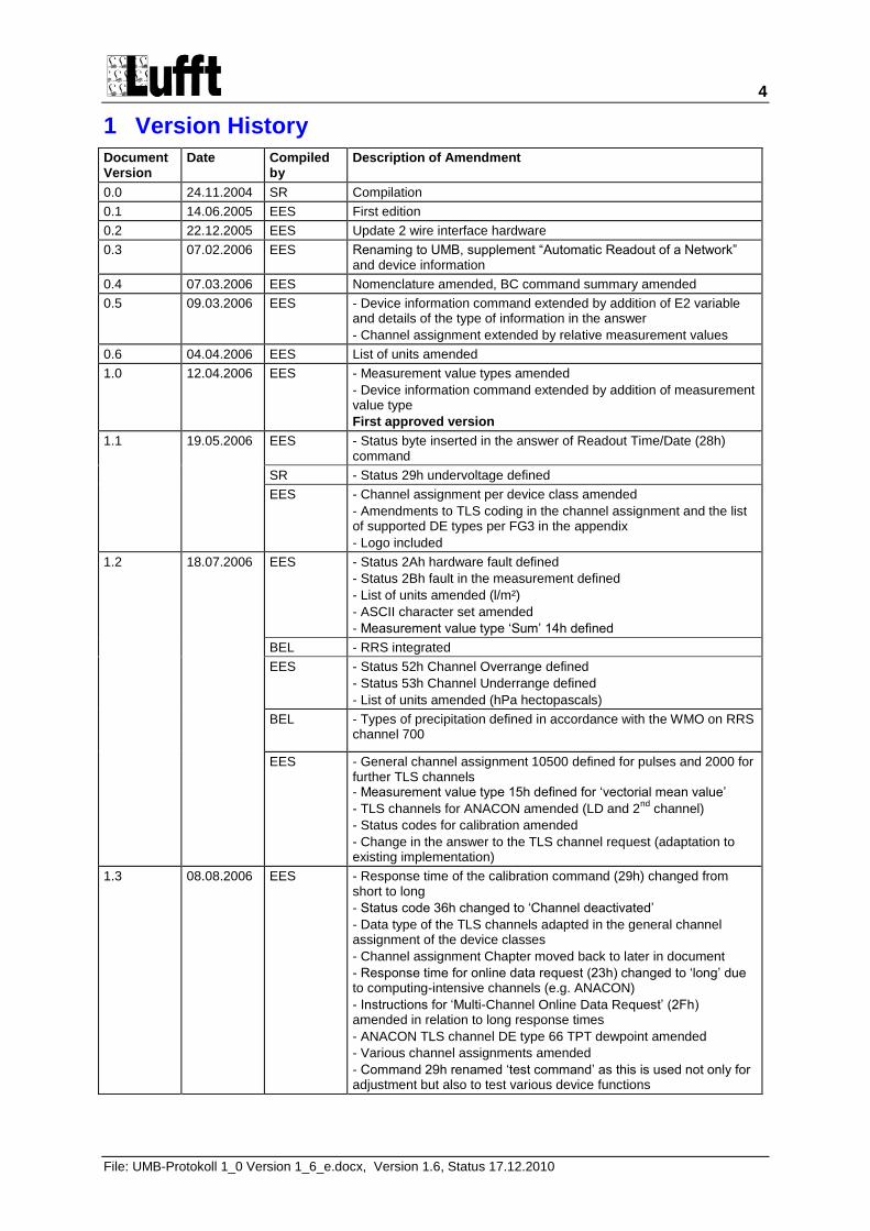
1 Version History
Document Version
Date Compiled by
Description of Amendment
0.0 24.11.2004 SR Compilation
0.1 14.06.2005 EES First edition
0.2 22.12.2005 EES Update 2 wire interface hardware
0.3 07.02.2006 EES Renaming to UMB, supplement “Automatic Readout of a Network” and device information
0.4 07.03.2006 EES Nomenclature amended, BC command summary amended
0.5 09.03.2006 EES - Device information command extended by addition of E2 variable and details of the type of information in the answer
- Channel assignment extended by relative measurement values
0.6 04.04.2006 EES List of units amended
1.0 12.04.2006 EES - Measurement value types amended
- Device information command extended by addition of measurement value type
First approved version
1.1 19.05.2006 EES - Status byte inserted in the answer of Readout Time/Date (28h) command
SR - Status 29h undervoltage defined
EES - Channel assignment per device class amended
- Amendments to TLS coding in the channel assignment and the list of supported DE types per FG3 in the appendix
- Logo included
1.2 18.07.2006 EES - Status 2Ah hardware fault defined
- Status 2Bh fault in the measurement defined
- List of units amended (l/m²)
- ASCII character set amended
- Measurement value type „Sum‟ 14h defined
BEL - RRS integrated
EES - Status 52h Channel Overrange defined
- Status 53h Channel Underrange defined
- List of units amended (hPa hectopascals)
BEL - Types of precipitation defined in accordance with the WMO on RRS channel 700
EES - General channel assignment 10500 defined for pulses and 2000 for further TLS channels - Measurement value type 15h defined for „vectorial mean value‟
- TLS channels for ANACON amended (LD and 2nd
channel)
- Status codes for calibration amended
- Change in the answer to the TLS channel request (adaptation to existing implementation)
1.3 08.08.2006 EES - Response time of the calibration command (29h) changed from short to long
- Status code 36h changed to „Channel deactivated‟
- Data type of the TLS channels adapted in the general channel assignment of the device classes
- Channel assignment Chapter moved back to later in document
- Response time for online data request (23h) changed to „long‟ due to computing-intensive channels (e.g. ANACON)
- Instructions for „Multi-Channel Online Data Request‟ (2Fh) amended in relation to long response times
- ANACON TLS channel DE type 66 TPT dewpoint amended
- Various channel assignments amended
- Command 29h renamed „test command‟ as this is used not only for adjustment but also to test various device functions
5
File: UMB-Protokoll 1_0 Version 1_6_e.docx, Version 1.6, Status 17.12.2010
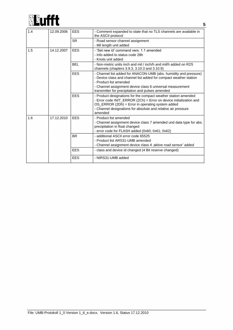
1.4 12.09.2006 EES - Comment expanded to state that no TLS channels are available in the ASCII protocol
SR - Road sensor channel assignment
- Mil length unit added
1.5 14.12.2007 EES - „Set new id‟ command vers. 1.1 amended
- Info added to status code 28h
- Knots unit added
BEL - Non-metric units inch and mil / inch/h and mil/h added on R2S channels (chapters 3.9.3, 3.10.3 and 3.10.9)
EES
- Channel list added for ANACON-UMB (abs. humidity and pressure) - Device class and channel list added for compact weather station
- Product list amended
- Channel assignment device class 6 universal measurement transmitter for precipitation and pulses amended
EES - Product designations for the compact weather station amended
- Error code INIT_ERROR (2Ch) = Error on device initialization and OS_ERROR (2Dh) = Error in operating system added
- Channel designations for absolute and relative air pressure amended
1.6 17.12.2010 EES - Product list amended
- Channel assignment device class 7 amended und data type for abs. precipitation in float changed
- error code for FLASH added (0x60; 0x61; 0x62)
BR - additional ASCII error code 65525
- Product list ARS31-UMB amended
- Channel assignment device class 4 ‚aktive road sensor‟ added
EES - class and device id changed (4 Bit reserve changed)
EES - NIRS31-UMB added
6
File: UMB-Protokoll 1_0 Version 1_6_e.docx, Version 1.6, Status 17.12.2010
2 Preliminary Remarks
The protocols described here were developed for meteorological sensors and facilitate simplified communication with various devices such as IRS31-UMB, VS20-UMB and R2S-UMB.
2.1 Restricted Guarantee The methods and settings described in this document allow the device to be configured using standard PC software. The selection of incorrect settings can lead to the loss of the specified measurement accuracy and device failure. Lufft reserves the right to restrict the guarantee to the products in the case of the application of the procedures described here.
2.2 Nomenclature Device: The term “device” is used in this document as a synonym for the equipment family of meteorological sensors such as IRS31, VS20 and R2S.
Hexadecimal values are identified by the suffix „h‟. Decimal values are identified by the suffix „d‟.
„BC‟ identifies commands which can be transmitted by broadcast. „NBC‟ stands for „not broadcastable‟ (please also see Comments about Broadcast on page 34).
2.3 Data Format and Byte Order in the Communication Protocol: LONG: LowLowByte LowHighByte HighLowByte HighHighByte
INT: LowByte HighByte
FLOAT: Per IEEE format (4 bytes)
2.4 Physical Connection and Hardware Structure In a network, the device is controlled via a half-duplex RS485 2 wire interface. The ISOCON also has an RS232 interface. The factory-set baud rate is 19200 baud with 8 data bits, one stop bit and no parity (8N1).
2.5 Software Protocol Configuration and polling of the device takes place in binary protocol. As the system operates without collision detection, the master-slave principle is strictly observed. In order to simplify communication,especially for polling measurement values, it is possible to switch over to ASCII protocol (although not all products currently support this feature). In doing so, it should be noted that it is not possible to configure the device in ASCII protocol and the measurement values are not CRC-safe. In addition, TLS channels are not available here.
7
File: UMB-Protokoll 1_0 Version 1_6_e.docx, Version 1.6, Status 17.12.2010
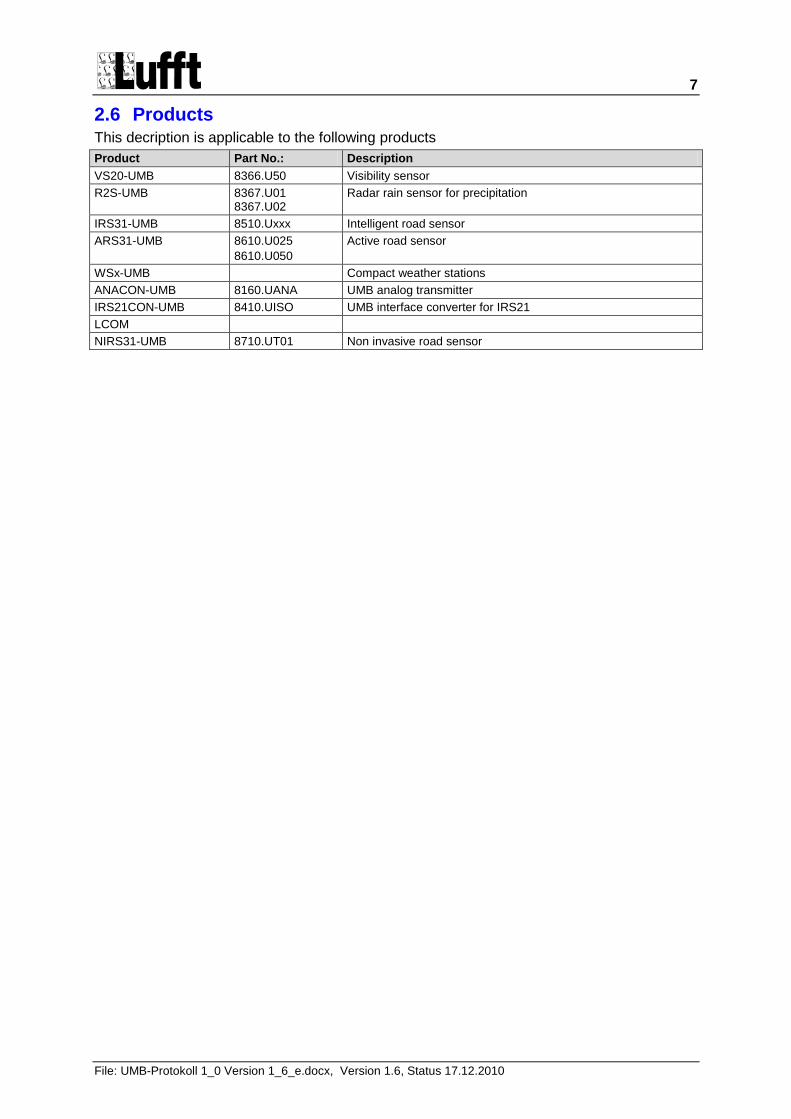
2.6 Products This decription is applicable to the following products
Product Part No.: Description
VS20-UMB 8366.U50 Visibility sensor
R2S-UMB 8367.U01 8367.U02
Radar rain sensor for precipitation
IRS31-UMB 8510.Uxxx Intelligent road sensor
ARS31-UMB 8610.U025
8610.U050
Active road sensor
WSx-UMB Compact weather stations
ANACON-UMB 8160.UANA UMB analog transmitter
IRS21CON-UMB 8410.UISO UMB interface converter for IRS21
LCOM
NIRS31-UMB 8710.UT01 Non invasive road sensor
8
File: UMB-Protokoll 1_0 Version 1_6_e.docx, Version 1.6, Status 17.12.2010
3 UMB Binary Protocol (Version 1.0)
The OSI (Open Systems Interconnection) reference model of the International Standards Organisation (ISO) can be used to abstract the logical steps of the header construction.
The datagrams pass through the individual layers of the protocol stack and in doing so are progressively provided with the header data. In this way a frame is created, the maximum length of which is limited to 255 bytes. 210 bytes are available for reference data.
Little endian is applicable to the transmission of word variables (Intel, lowbyte first).
3.1 Protocol Stack (Framing)
3.1.1 Application Layer
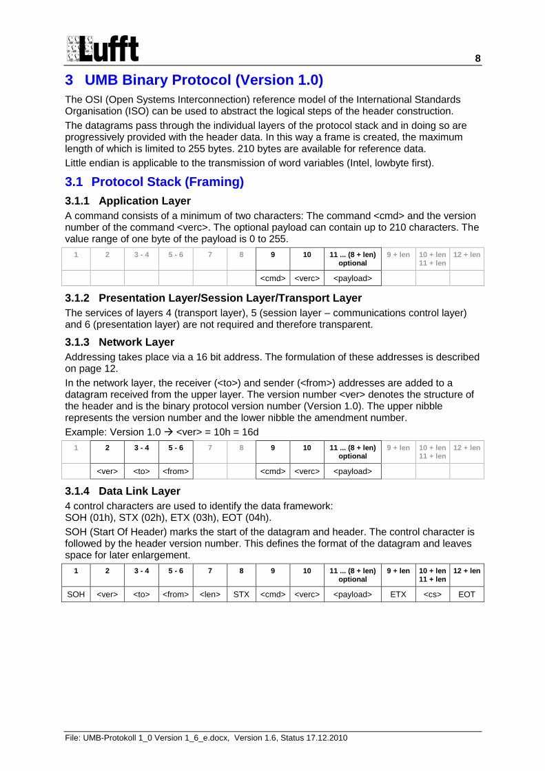
A command consists of a minimum of two characters: The command <cmd> and the version number of the command <verc>. The optional payload can contain up to 210 characters. The value range of one byte of the payload is 0 to 255.
1 2 3 - 4 5 - 6 7 8 9 10 11 ... (8 + len) optional
9 + len 10 + len 11 + len
12 + len
<cmd> <verc> <payload>
3.1.2 Presentation Layer/Session Layer/Transport Layer
The services of layers 4 (transport layer), 5 (session layer – communications control layer) and 6 (presentation layer) are not required and therefore transparent.
3.1.3 Network Layer
Addressing takes place via a 16 bit address. The formulation of these addresses is described on page 12.
In the network layer, the receiver (<to>) and sender (<from>) addresses are added to a datagram received from the upper layer. The version number <ver> denotes the structure of the header and is the binary protocol version number (Version 1.0). The upper nibble represents the version number and the lower nibble the amendment number.
Example: Version 1.0 <ver> = 10h = 16d
1 2 3 - 4 5 - 6 7 8 9 10 11 ... (8 + len) optional
9 + len 10 + len 11 + len
12 + len
<ver> <to> <from> <cmd> <verc> <payload>
3.1.4 Data Link Layer
4 control characters are used to identify the data framework: SOH (01h), STX (02h), ETX (03h), EOT (04h).
SOH (Start Of Header) marks the start of the datagram and header. The control character is followed by the header version number. This defines the format of the datagram and leaves space for later enlargement.
1 2 3 - 4 5 - 6 7 8 9 10 11 ... (8 + len) optional
9 + len 10 + len 11 + len
12 + len
SOH <ver> <to> <from> <len> STX <cmd> <verc> <payload> ETX <cs> EOT
9
File: UMB-Protokoll 1_0 Version 1_6_e.docx, Version 1.6, Status 17.12.2010
3.1.5 Physical Layer
2 wire RS485, standard baud rate 19200 baud, 8 data bits, 1 stop bit and no parity.
3.1.6 Timing Sensor
The following criteria have been defined for the implementation of the protocol in the sensor:
- The receive interrupt can be blocked for critical measurements.
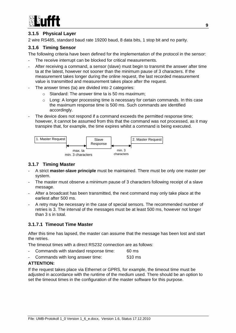
- After receiving a command, a sensor (slave) must begin to transmit the answer after time ta at the latest, however not sooner than the minimum pause of 3 characters. If the measurement takes longer during the online request, the last recorded measurement value is transmitted and measurement takes place after the request.
- The answer times (ta) are divided into 2 categories:
o Standard: The answer time ta is 50 ms maximum;
o Long: A longer processing time is necessary for certain commands. In this case the maximum response time is 500 ms. Such commands are identified accordingly.
- The device does not respond if a command exceeds the permitted response time; however, it cannot be assumed from this that the command was not processed, as it may transpire that, for example, the time expires whilst a command is being executed.
3.1.7 Timing Master
- A strict master-slave principle must be maintained. There must be only one master per system.
- The master must observe a minimum pause of 3 characters following receipt of a slave message.
- After a broadcast has been transmitted, the next command may only take place at the earliest after 500 ms.
- A retry may be necessary in the case of special sensors. The recommended number of retries is 3. The interval of the messages must be at least 500 ms, however not longer than 3 s in total.
3.1.7.1 Timeout Time Master
After this time has lapsed, the master can assume that the message has been lost and start the retries.
The timeout times with a direct RS232 connection are as follows:
- Commands with standard response time: 60 ms
- Commands with long answer time: 510 ms
ATTENTION:
If the request takes place via Ethernet or GPRS, for example, the timeout time must be adjusted in accordance with the runtime of the medium used. There should be an option to set the timeout times in the configuration of the master software for this purpose.
1. Master Request Slave Response
max. ta
min. 3 characters
2. Master Request
min. 3 characters
10
File: UMB-Protokoll 1_0 Version 1_6_e.docx, Version 1.6, Status 17.12.2010
3.1.8 Summary
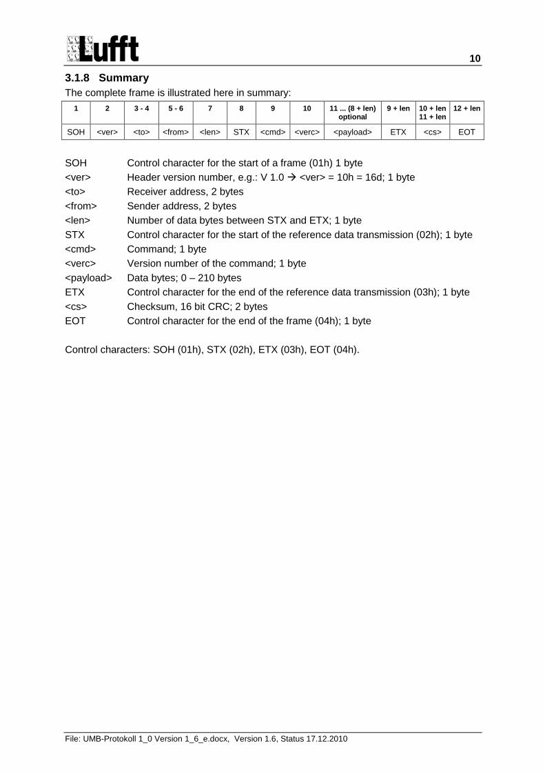
The complete frame is illustrated here in summary:
1 2 3 - 4 5 - 6 7 8 9 10 11 ... (8 + len) optional
9 + len 10 + len 11 + len
12 + len
SOH <ver> <to> <from> <len> STX <cmd> <verc> <payload> ETX <cs> EOT
SOH Control character for the start of a frame (01h) 1 byte
<ver> Header version number, e.g.: V 1.0 <ver> = 10h = 16d; 1 byte
<to> Receiver address, 2 bytes
<from> Sender address, 2 bytes
<len> Number of data bytes between STX and ETX; 1 byte
STX Control character for the start of the reference data transmission (02h); 1 byte
<cmd> Command; 1 byte
<verc> Version number of the command; 1 byte
<payload> Data bytes; 0 – 210 bytes
ETX Control character for the end of the reference data transmission (03h); 1 byte
<cs> Checksum, 16 bit CRC; 2 bytes
EOT Control character for the end of the frame (04h); 1 byte
Control characters: SOH (01h), STX (02h), ETX (03h), EOT (04h).
11
File: UMB-Protokoll 1_0 Version 1_6_e.docx, Version 1.6, Status 17.12.2010
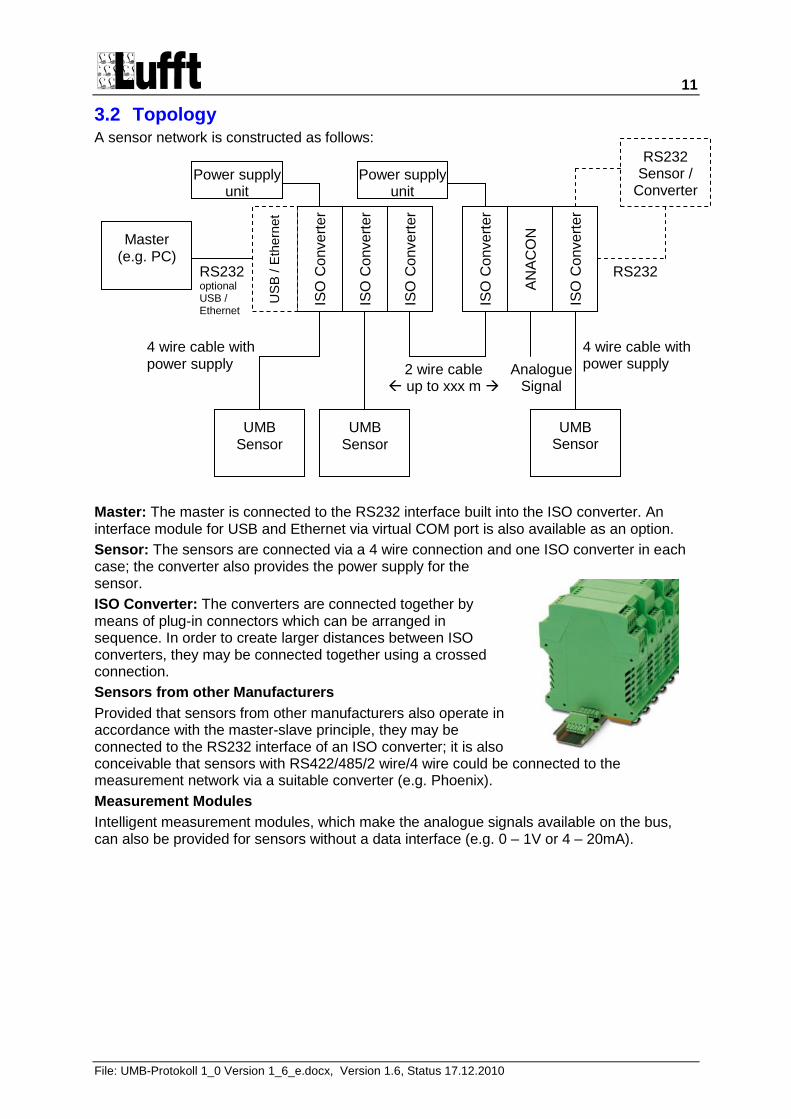
3.2 Topology A sensor network is constructed as follows:
Master: The master is connected to the RS232 interface built into the ISO converter. An interface module for USB and Ethernet via virtual COM port is also available as an option.
Sensor: The sensors are connected via a 4 wire connection and one ISO converter in each case; the converter also provides the power supply for the sensor.
ISO Converter: The converters are connected together by means of plug-in connectors which can be arranged in sequence. In order to create larger distances between ISO converters, they may be connected together using a crossed connection.
Sensors from other Manufacturers
Provided that sensors from other manufacturers also operate in accordance with the master-slave principle, they may be connected to the RS232 interface of an ISO converter; it is also conceivable that sensors with RS422/485/2 wire/4 wire could be connected to the measurement network via a suitable converter (e.g. Phoenix).
Measurement Modules
Intelligent measurement modules, which make the analogue signals available on the bus, can also be provided for sensors without a data interface (e.g. 0 – 1V or 4 – 20mA).
ISO
Co
nve
rte
r
ISO
Co
nve
rte
r
ISO
Co
nve
rte
r
UMB Sensor
UMB Sensor
UMB Sensor
Master (e.g. PC)
ISO
Co
nve
rte
r
ISO
Co
nve
rte
r
RS232 Sensor /
Converter Power supply
unit Power supply
unit
2 wire cable up to xxx m
4 wire cable with power supply
4 wire cable with power supply
RS232 RS232 optional USB / Ethernet
AN
AC
ON
Analogue Signal
US
B / E
thern
et
12
File: UMB-Protokoll 1_0 Version 1_6_e.docx, Version 1.6, Status 17.12.2010
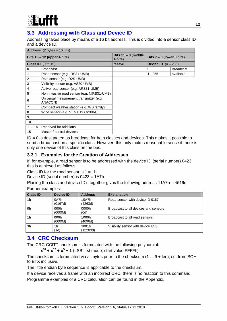
3.3 Addressing with Class and Device ID Addressing takes place by means of a 16 bit address. This is divided into a sensor class ID and a device ID.
Address (2 bytes = 16 bits)
Bits 15 – 12 (upper 4 bits) Bits 11 – 8 (middle 4 bits)
Bits 7 – 0 (lower 8 bits)
Class ID (0 to 15) reseve Device ID (0 – 255)
0 Broadcast 0 Broadcast
1 Road sensor (e.g. IRS31-UMB) 1 - 255 available
2 Rain sensor (e.g. R2S-UMB)
3 Visibility sensor (e.g. VS20-UMB)
4 Active road sensor (e.g. ARS31-UMB)
5 Non invasive road sensor (e.g. NIRS31-UMB)
6 Universal measurement transmitter (e.g. ANACON)
7 Compact weather station (e.g. WS family)
8 Wind sensor (e.g. VENTUS / V200A)
9
10
11 - 14 Reserved for additions
15 Master / control devices
ID = 0 is designated as broadcast for both classes and devices. This makes it possible to send a broadcast on a specific class. However, this only makes reasonable sense if there is only one device of this class on the bus.
3.3.1 Examples for the Creation of Addresses
If, for example, a road sensor is to be addressed with the device ID (serial number) 0423, this is achieved as follows:
Class ID for the road sensor is 1 = 1h Device ID (serial number) is 0423 = 1A7h
Placing the class and device ID‟s together gives the following address 11A7h = 4519d.
Further examples:
Class ID Device ID Address Explanation
1h 0A7h (0167d)
10A7h (4263d)
Road sensor with device ID 0167
0h
000h (0000d)
0000h (0d)
Broadcast to all devices and sensors
1h
000h (0000d)
1000h (4096d)
Broadcast to all road sensors
3h
1h (1d)
3001h (12289d)
Visibility sensor with device ID 1
3.4 CRC Checksum The CRC-CCITT checksum is formulated with the following polynomial:
x16 + x12 + x5 + 1 (LSB first mode; start value FFFFh)
The checksum is formulated via all bytes prior to the checksum (1 ... 9 + len), i.e. from SOH to ETX inclusive.
The little endian byte sequence is applicable to the checksum.
If a device receives a frame with an incorrect CRC, there is no reaction to this command.
Programme examples of a CRC calculation can be found in the Appendix.
13
File: UMB-Protokoll 1_0 Version 1_6_e.docx, Version 1.6, Status 17.12.2010
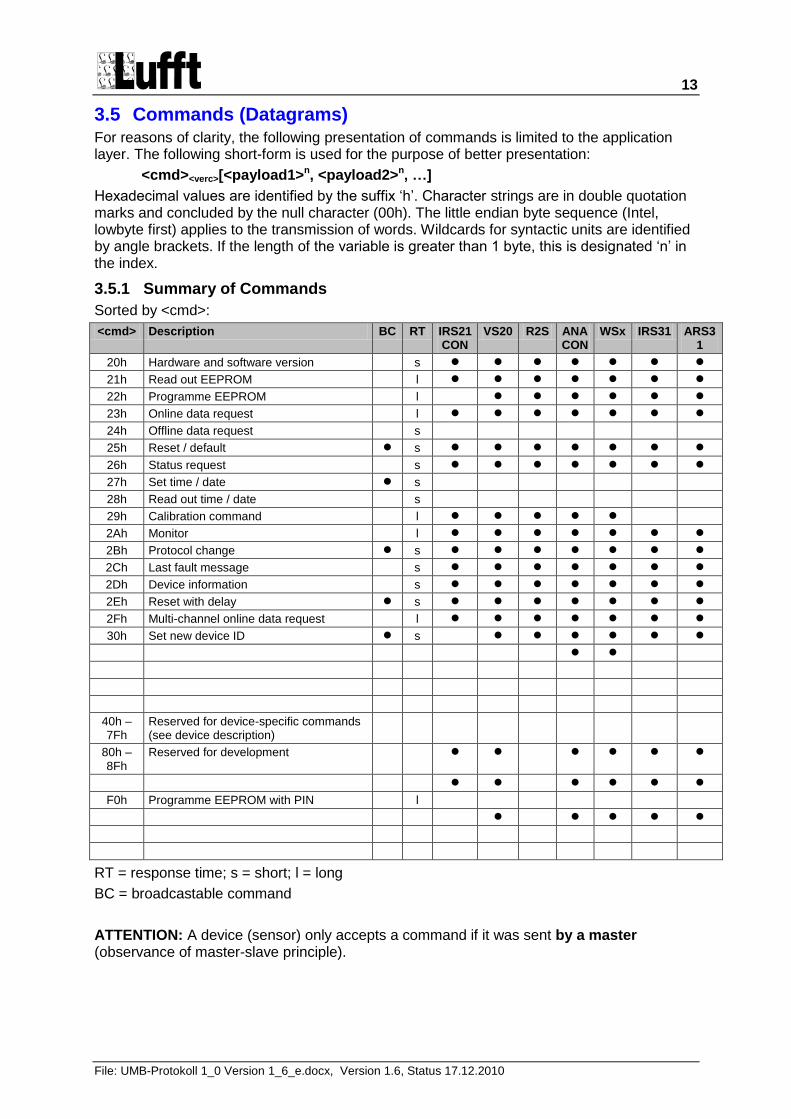
3.5 Commands (Datagrams) For reasons of clarity, the following presentation of commands is limited to the application layer. The following short-form is used for the purpose of better presentation:
<cmd><verc>[<payload1>n, <payload2>n, …]
Hexadecimal values are identified by the suffix „h‟. Character strings are in double quotation marks and concluded by the null character (00h). The little endian byte sequence (Intel, lowbyte first) applies to the transmission of words. Wildcards for syntactic units are identified by angle brackets. If the length of the variable is greater than 1 byte, this is designated „n‟ in the index.
3.5.1 Summary of Commands
Sorted by <cmd>:
<cmd> Description BC RT IRS21CON
VS20 R2S ANACON
WSx IRS31 ARS31
20h Hardware and software version s
21h Read out EEPROM l
22h Programme EEPROM l
23h Online data request l
24h Offline data request s
25h Reset / default s
26h Status request s
27h Set time / date s
28h Read out time / date s
29h Calibration command l
2Ah Monitor l
2Bh Protocol change s
2Ch Last fault message s
2Dh Device information s
2Eh Reset with delay s
2Fh Multi-channel online data request l
30h Set new device ID s
40h – 7Fh
Reserved for device-specific commands (see device description)
80h – 8Fh
Reserved for development
F0h Programme EEPROM with PIN l
RT = response time; s = short; l = long
BC = broadcastable command
ATTENTION: A device (sensor) only accepts a command if it was sent by a master (observance of master-slave principle).
14
File: UMB-Protokoll 1_0 Version 1_6_e.docx, Version 1.6, Status 17.12.2010
3.5.2 Hardware and Software Version (20h)
Command <cmd>: 20h (NBC)
Command version <verc>: 1.0
Data <payload>: none
Description: This command serves to request the hardware and software version of the addressed device.
Call: 20h10h[ ]
Answer: 20h10h[00h, <hardware>, <software>]
Example: SW-Version 2.3 <software> = 17h = 23d HW-Version 6 <hardware> = 06h = 6d
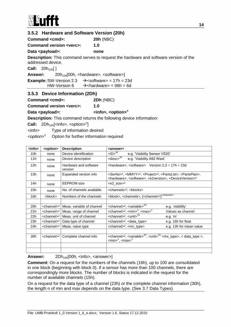
3.5.3 Device Information (2Dh)
Command <cmd>: 2Dh (NBC)
Command version <verc>: 1.0
Data <payload>: <info>, <option>n
Description: This command returns the following device information:
Call: 2Dh10h[<info>, <option>n]
<info> Type of information desired
<option>n Option for further information required
<info> <option> Description <answer>
10h none Device identification <ID>40
e.g. „Visibility Sensor VS20‟
11h none Device description <desc>40
e.g. „Visibility A92 West‟
12h none Hardware and software version
<hardware>, <software> Version 2.3 = 17h = 23d
13h none Expanded version info <SerNo>², <MMYY>², <Project>², <PartsList>, <PartsPlan>, <hardware>, <software>, <e2version>, <DeviceVersion>²
14h none EEPROM size <e2_size>²
15h none No. of channels available <channels>², <blocks>
16h <block> Numbers of the channels <block>, <channels>, [<channel>²]<channels>
20h <channel>² Meas. variable of channel <channel>², <variable>20
e.g. „visibility‟
21h <channel>² Meas. range of channel <channel>², <min>n, <max>
n Values as channel
22h <channel>² Meas. unit of channel <channel>², <unit>15
e.g. „m‟
23h <channel>² Data type of channel <channel>², <data_type> e.g. 16h for float
24h <channel>² Meas. value type <channel>², <mv_type> e.g. 13h for mean value
30h <channel>² Complete channel info <channel>², <variable>20
, <unit>15,
<mv_type>, < data_type >, <min>
n, <max>
n
Answer: 2Dh10h[00h, <info>, <answer>]
Comment: On a request for the numbers of the channels (16h), up to 100 are consolidated in one block (beginning with block 0). If a sensor has more than 100 channels, there are correspondingly more blocks. The number of blocks is indicated in the request for the number of available channels (15h).
On a request for the data type of a channel (23h) or the complete channel information (30h), the length n of min and max depends on the data type. (See 3.7 Data Types)
15
File: UMB-Protokoll 1_0 Version 1_6_e.docx, Version 1.6, Status 17.12.2010
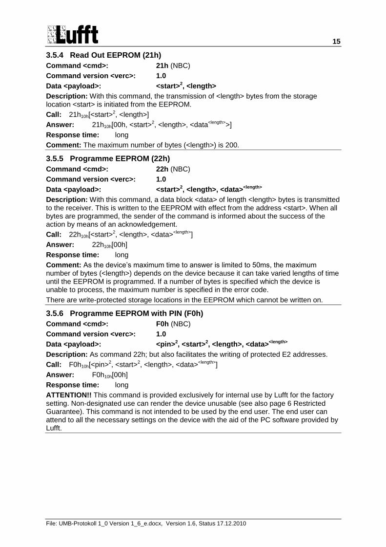
3.5.4 Read Out EEPROM (21h)
Command <cmd>: 21h (NBC)
Command version <verc>: 1.0
Data <payload>: <start>2, <length>
Description: With this command, the transmission of <length> bytes from the storage location <start> is initiated from the EEPROM.
Call: 21h10h[<start>2, <length>]
Answer: 21h10h[00h, <start>2, <length>, <data<length>>]
Response time: long
Comment: The maximum number of bytes (<length>) is 200.
3.5.5 Programme EEPROM (22h)
Command <cmd>: 22h (NBC)
Command version <verc>: 1.0
Data <payload>: <start>2, <length>, <data><length>
Description: With this command, a data block <data> of length <length> bytes is transmitted to the receiver. This is written to the EEPROM with effect from the address <start>. When all bytes are programmed, the sender of the command is informed about the success of the action by means of an acknowledgement.
Call: 22h10h[<start>2, <length>, <data><length>]
Answer: 22h10h[00h]
Response time: long
Comment: As the device‟s maximum time to answer is limited to 50ms, the maximum number of bytes (<length>) depends on the device because it can take varied lengths of time until the EEPROM is programmed. If a number of bytes is specified which the device is unable to process, the maximum number is specified in the error code.
There are write-protected storage locations in the EEPROM which cannot be written on.
3.5.6 Programme EEPROM with PIN (F0h)
Command <cmd>: F0h (NBC)
Command version <verc>: 1.0
Data <payload>: <pin>2, <start>2, <length>, <data><length>
Description: As command 22h; but also facilitates the writing of protected E2 addresses.
Call: F0h10h[<pin>2, <start>2, <length>, <data><length>]
Answer: F0h10h[00h]
Response time: long
ATTENTION!! This command is provided exclusively for internal use by Lufft for the factory setting. Non-designated use can render the device unusable (see also page 6 Restricted Guarantee). This command is not intended to be used by the end user. The end user can attend to all the necessary settings on the device with the aid of the PC software provided by Lufft.
16
File: UMB-Protokoll 1_0 Version 1_6_e.docx, Version 1.6, Status 17.12.2010
3.5.7 Online Data Request (23h)
Command <cmd>: 23h (NBC)
Command version <verc>: 1.0
Data <payload>: <channel>²
Description: A measurement value of a certain channel is requested with this command.
Call: 23h10h[<channel>²]
Answer: 23h10h[00h, <channel>², <type>, <value>n]
Response time: long
<channel>² designates the channel number
<type> designates the data type of the output; the length of <value> depends on this (see page 22 - Data Types)
<value>n requested value
Comment: The device description specifies the channel on which the transmission is to be made as well as the measurement value and format to be transmitted.
3.5.8 Multi-Channel Online Data Request (2Fh)
Command <cmd>: 2Fh (NBC)
Command version <verc>: 1.0
Data <payload>: <number>, <channel>²
Description: This command serves to request several channels with one call. A sub-telegram is transmitted for each channel.
Call: 2Fh10h[<number>, <channel>2 x <number>]
<number> number of channels requested
<channel>² designates the channel numbers
Answer: 2Fh10h[00h, <number>, {<sub-len>, 00h, <channel>², <type>, <value>n}<number>]
Response time: long
<sub-len> designates the number of bytes contained in this sub-telegram; if the subsequent status byte displays, for example, „Value Overflow‟, <type> and <value>n are omitted and the next channel follows
<type> designates the data type of the output; the length of <value> depends on this (see page 22 - Data Types)
<value>n requested value
Comment: The device description specifies the channel on which the transmission is to be made as well as the measurement value and format to be transmitted. A maximum of 20 channels can be requested.
ATTENTION!! In the case of computing-intensive channels, such as the calculation of the mean average for wind in the ANACON, under certain circumstances the response time „long‟ may not be sufficient for the transmission of several channels. If the sensor does not respond to the request, either the number of channels or the number of values in the mean value calculation must be reduced.
17
File: UMB-Protokoll 1_0 Version 1_6_e.docx, Version 1.6, Status 17.12.2010
3.5.9 Offline Data Request (24h)
Command <cmd>: 24h (NBC)
Command version <verc>: 1.0
Not currently specified.
3.5.10 Reset / Default (25h)
Command <cmd>: 25h (BC)
Command version <verc>: 1.0
Data <payload>: <reset>
Description: This command triggers a software reset. Alternatively, a specified condition can be restored prior to the reset.
Call: 25h10h[<reset>]
<reset> 10h triggers software reset 11h restore condition as delivered + software reset 12h restore device ID to condition as delivered + software reset 13h Device-specific command (see relevant specification)
Answer: 25h10h[00h]
Comment: The answer takes place directly prior to the reset.
3.5.11 Reset with Delay (2Eh)
Command <cmd>: 2Eh (BC)
Command version <verc>: 1.0
Data <payload>: <delay>
Description: This command triggers a software reset after expiry of the delay period <delay> (e.g. for firmware update).
Call: 2Eh10h[<delay>]
<delay> Delay period in seconds (max. 255)
Answer: 2Eh10h[00h]
Comment: The answer takes place at the beginning of the delay period.
3.5.12 Status Request (26h)
Command <cmd>: 26h (NBC)
Command version <verc>: 1.0
Data <payload>: none
Description: Readout of the current status and/or error codes; thus the device can be asked if it is operating free from error.
Call: 26h10h[ ]
Answer: 26h10h[00h, <status>]
3.5.13 Last Error Message (2Ch)
Command <cmd>: 2Ch (NBC)
Command version <verc>: 1.0
Data <payload>: none
Description: Indicates the error code of the last response of the device with regard to communication. E.g. invalid parameter
Call: 2Ch10h[ ]
Answer: 2Ch10h[00h, <error>]
18
File: UMB-Protokoll 1_0 Version 1_6_e.docx, Version 1.6, Status 17.12.2010
3.5.14 Set Time / Date (27h)
Command <cmd>: 27h (BC)
Command version <verc>: 1.0
Data <payload>: <unixtime>4
Description: Sets the date and time of the addressed device.
Call: 27h10h[<unixtime>4]
Answer: 27h10h[00h]
Comment: Unixtime is the 4 byte hexadecimal number with the lowest value byte (LSB) first, which corresponds to the seconds since 1.1.1970 0:00 UTC.
3.5.15 Readout Time / Date (28h)
Command <cmd>: 28h (NBC)
Command version <verc>: 1.0
Data <payload>: none
Description: Reads out the date and time of the addressed device.
Call: 28h10h[ ]
Answer: 28h10h[00h, <unixtime>4]
Comment: Unixtime is the 4 byte hexadecimal number with the lowest value byte (LSB) first, which corresponds to the seconds since 1.1.1970 0:00 UTC.
3.5.16 Test / Calibration Command (29h)
Command <cmd>: 29h (NBC)
Command version <verc>: 1.0
Data <payload>: <pin>², <function>, <data>n
Description: This command serves to calibrate and test the device
Call: 29h10h[<pin>², <function>, <data>n]
Answer: 29h10h[00h, ..., ...] (device-specific)
Response time: 2 x long !
ATTENTION!! This command is provided exclusively for internal use by Lufft for the factory setting. Non-designated use can render the device unusable (see also page 6 Restricted Guarantee). The test functions are contained in the device specification.
3.5.17 Monitor (2Ah)
Command <cmd>: 2Ah (NBC)
Command version <verc>: 1.0
Data <payload>: <monitor>n
Description: Device-specific functions can be executed through the PC software with the aid of monitor commands (see respective device specification).
Call: 2Ah10h[<monitor command>n]
Answer: 2Ah10h[00h, <answer>n]
Response time: long
ATTENTION!! This command is provided exclusively for internal use by Lufft for the factory setting. Non-designated use can render the device unusable.
This command is specified in the respective device specification.
19
File: UMB-Protokoll 1_0 Version 1_6_e.docx, Version 1.6, Status 17.12.2010
3.5.18 Protocol Change (2Bh)
Command <cmd>: 2Bh (BC)
Command version <verc>: 1.0
Data <payload>: <type>
Description: Temporarily switches the device into another protocol.
Call: 2Bh10h[<type>]
<type> 10h ASCII protocol
Answer: 2Bh10h[00h]
ATTENTION!! Immediately following the answer, the device can only be addressed in the new protocol. If the device is required to operate again in, for example, binary mode, the corresponding command must be given for a change of protocol to binary mode.
The protocol changeover is temporary!! Following a reset or device-specific timeout the device communicates again in the previously set mode. If the device is to be operated permanently in, for example, ASCII mode, the device specification must be changed in the EEPROM.
3.5.19 Set New Device ID (30h)
Command <cmd>: 30h (BC)
Command version <verc>: 1.0
Data <payload>: <ID>²
Description: Gives the device a new ID.
Call: 30h10h[<ID>²]
<ID>² new device ID (1 – 4095)
Answer: 30h10h[00h]
ATTENTION!! A reset takes place immediately following the answer and after this the device can only be addressed with the new ID. Attention! This command is broadcastable. This enables devices of unknown ID to be provided with a new ID. However, this only makes reasonable sense if a maximum of one device is connected to the bus.
Command version <verc>: 1.1
Data <payload>: <ID>²
Description: Gives the device a temporary new ID.
Call: 30h11h[<ID>²]
<ID>² new device ID (1 – 4095)
Answer: 30h11h[00h]
ATTENTION!! A reset takes place immediately following the answer and after this the device can only be addressed with the new ID. Attention! This command is broadcastable. This enables devices of unknown ID to be provided with a new ID. However, this only makes reasonable sense if a maximum of one device is connected to the bus.
20
File: UMB-Protokoll 1_0 Version 1_6_e.docx, Version 1.6, Status 17.12.2010
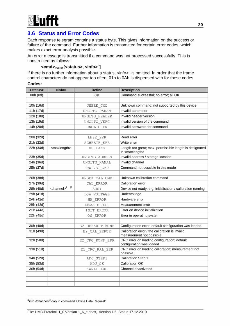
3.6 Status and Error Codes Each response telegram contains a status byte. This gives information on the success or failure of the command. Further information is transmitted for certain error codes, which makes exact error analysis possible.
An error message is transmitted if a command was not processed successfully. This is constructed as follows:
<cmd><verc>[<status>, <info>n]
If there is no further information about a status, <info>n is omitted. In order that the frame control characters do not appear too often, 01h to 0Ah is dispensed with for these codes.
Codes:
<status> <info> Define Description
00h (0d) OK Command successful; no error; all OK
10h (16d) UNBEK_CMD Unknown command; not supported by this device
11h (17d) UNGLTG_PARAM Invalid parameter
12h (18d) UNGLTG_HEADER Invalid header version
13h (19d) UNGLTG_VERC Invalid version of the command
14h (20d) UNGLTG_PW Invalid password for command
20h (32d) LESE_ERR Read error
21h (33d) SCHREIB_ERR Write error
22h (34d) <maxlength> ZU_LANG Length too great; max. permissible length is designated in <maxlength>
23h (35d) UNGLTG_ADRESS Invalid address / storage location
24h (36d) UNGLTG_KANAL Invalid channel
25h (37d) UNGLTG_CMD Command not possible in this mode
26h (38d) UNBEK_CAL_CMD Unknown calibration command
27h (39d) CAL_ERROR Calibration error
28h (40d) <channel>2
(1 BUSY Device not ready; e.g. initialisation / calibration running
29h (41d) LOW_VOLTAGE Undervoltage
2Ah (42d) HW_ERROR Hardware error
2Bh (43d) MEAS_ERROR Measurement error
2Ch (44d) INIT_ERROR Error on device initialization
2Dh (45d) OS_ERROR Error in operating system
30h (48d) E2_DEFAULT_KONF Configuration error, default configuration was loaded
31h (49d) E2_CAL_ERROR Calibration error / the calibration is invalid, measurement not possible
32h (50d) E2_CRC_KONF_ERR CRC error on loading configuration; default configuration was loaded
33h (51d) E2_CRC_KAL_ERR CRC error on loading calibration; measurement not possible
34h (52d) ADJ_STEP1 Calibration Step 1
35h (53d) ADJ_OK Calibration OK
36h (54d) KANAL_AUS Channel deactivated
(1info <channel>
2 only in command „Online Data Request‟
21
File: UMB-Protokoll 1_0 Version 1_6_e.docx, Version 1.6, Status 17.12.2010
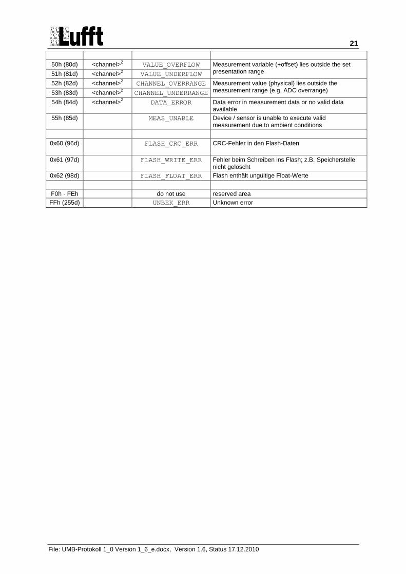
50h (80d) <channel>2 VALUE_OVERFLOW Measurement variable (+offset) lies outside the set
presentation range 51h (81d) <channel>2 VALUE_UNDERFLOW
52h (82d) <channel>2 CHANNEL_OVERRANGE Measurement value (physical) lies outside the
measurement range (e.g. ADC overrange) 53h (83d) <channel>2 CHANNEL_UNDERRANGE
54h (84d) <channel>2 DATA_ERROR Data error in measurement data or no valid data
available
55h (85d) MEAS_UNABLE Device / sensor is unable to execute valid measurement due to ambient conditions
0x60 (96d)
FLASH_CRC_ERR CRC-Fehler in den Flash-Daten
0x61 (97d) FLASH_WRITE_ERR Fehler beim Schreiben ins Flash; z.B. Speicherstelle nicht gelöscht
0x62 (98d) FLASH_FLOAT_ERR Flash enthält ungültige Float-Werte
F0h - FEh do not use reserved area
FFh (255d) UNBEK_ERR Unknown error
22
File: UMB-Protokoll 1_0 Version 1_6_e.docx, Version 1.6, Status 17.12.2010
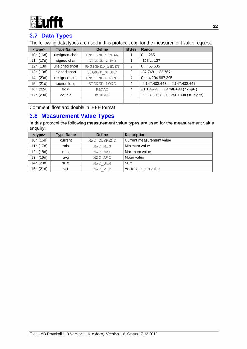
3.7 Data Types The following data types are used in this protocol, e.g. for the measurement value request:
<type> Type Name Define Bytes Range
10h (16d) unsigned char UNSIGNED_CHAR 1 0 ... 255
11h (17d) signed char SIGNED_CHAR 1 -128 ... 127
12h (18d) unsigned short UNSIGNED_SHORT 2 0 ... 65.535
13h (19d) signed short SIGNED_SHORT 2 -32.768 ... 32.767
14h (20d) unsigned long UNSIGNED_LONG 4 0 ... 4.294.967.295
15h (21d) signed long SIGNED_LONG 4 -2.147.483.648 ... 2.147.483.647
16h (22d) float FLOAT 4 ±1.18E-38 ... ±3.39E+38 (7 digits)
17h (23d) double DOUBLE 8 ±2.23E-308 ... ±1.79E+308 (15 digits)
Comment: float and double in IEEE format
3.8 Measurement Value Types In this protocol the following measurement value types are used for the measurement value enquiry:
<type> Type Name Define Description
10h (16d) current MWT_CURRENT Current measurement value
11h (17d) min MWT_MIN Minimum value
12h (18d) max MWT_MAX Maximum value
13h (19d) avg MWT_AVG Mean value
14h (20d) sum MWT_SUM Sum
15h (21d) vct MWT_VCT Vectorial mean value
23
File: UMB-Protokoll 1_0 Version 1_6_e.docx, Version 1.6, Status 17.12.2010
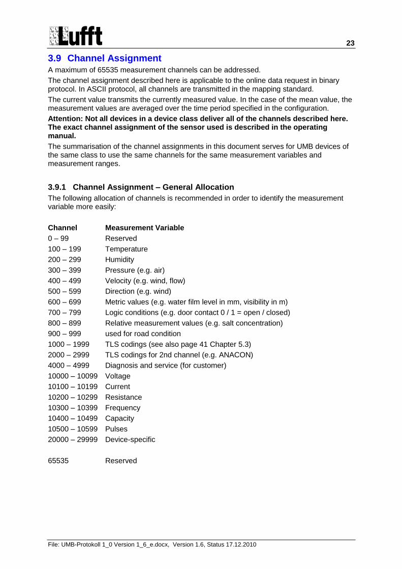
3.9 Channel Assignment A maximum of 65535 measurement channels can be addressed.
The channel assignment described here is applicable to the online data request in binary protocol. In ASCII protocol, all channels are transmitted in the mapping standard.
The current value transmits the currently measured value. In the case of the mean value, the measurement values are averaged over the time period specified in the configuration.
Attention: Not all devices in a device class deliver all of the channels described here. The exact channel assignment of the sensor used is described in the operating manual.
The summarisation of the channel assignments in this document serves for UMB devices of the same class to use the same channels for the same measurement variables and measurement ranges.
3.9.1 Channel Assignment – General Allocation
The following allocation of channels is recommended in order to identify the measurement variable more easily:
Channel Measurement Variable
0 – 99 Reserved
100 – 199 Temperature
200 – 299 Humidity
300 – 399 Pressure (e.g. air)
400 – 499 Velocity (e.g. wind, flow)
500 – 599 Direction (e.g. wind)
600 – 699 Metric values (e.g. water film level in mm, visibility in m)
700 – 799 Logic conditions (e.g. door contact 0 / 1 = open / closed)
800 – 899 Relative measurement values (e.g. salt concentration)
900 – 999 used for road condition
1000 – 1999 TLS codings (see also page 41 Chapter 5.3)
2000 – 2999 TLS codings for 2nd channel (e.g. ANACON)
4000 – 4999 Diagnosis and service (for customer)
10000 – 10099 Voltage
10100 – 10199 Current
10200 – 10299 Resistance
10300 – 10399 Frequency
10400 – 10499 Capacity
10500 – 10599 Pulses
20000 – 29999 Device-specific
65535 Reserved
24
File: UMB-Protokoll 1_0 Version 1_6_e.docx, Version 1.6, Status 17.12.2010
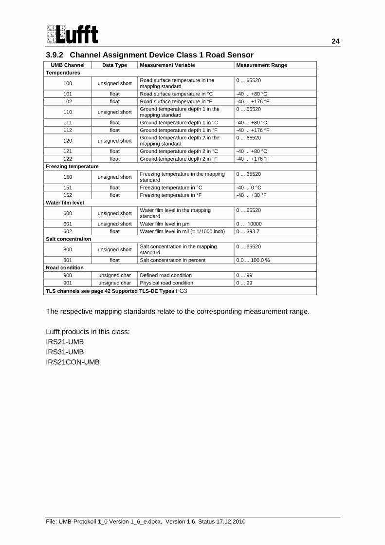
3.9.2 Channel Assignment Device Class 1 Road Sensor
UMB Channel Data Type Measurement Variable Measurement Range
Temperatures
100 unsigned short Road surface temperature in the mapping standard
0 ... 65520
101 float Road surface temperature in °C -40 ... +80 °C
102 float Road surface temperature in °F -40 ... +176 °F
110 unsigned short Ground temperature depth 1 in the mapping standard
0 ... 65520
111 float Ground temperature depth 1 in °C -40 ... +80 °C
112 float Ground temperature depth 1 in °F -40 ... +176 °F
120 unsigned short Ground temperature depth 2 in the mapping standard
0 ... 65520
121 float Ground temperature depth 2 in °C -40 ... +80 °C
122 float Ground temperature depth 2 in °F -40 ... +176 °F
Freezing temperature
150 unsigned short Freezing temperature in the mapping standard
0 ... 65520
151 float Freezing temperature in °C -40 ... 0 °C
152 float Freezing temperature in °F -40 ... +30 °F
Water film level
600 unsigned short Water film level in the mapping standard
0 ... 65520
601 unsigned short Water film level in µm 0 … 10000
602 float Water film level in mil (= 1/1000 inch) 0 ... 393.7
Salt concentration
800 unsigned short Salt concentration in the mapping standard
0 ... 65520
801 float Salt concentration in percent 0.0 ... 100.0 %
Road condition
900 unsigned char Defined road condition 0 ... 99
901 unsigned char Physical road condition 0 ... 99
TLS channels see page 42 Supported TLS-DE Types FG3
The respective mapping standards relate to the corresponding measurement range.
Lufft products in this class:
IRS21-UMB
IRS31-UMB
IRS21CON-UMB
25
File: UMB-Protokoll 1_0 Version 1_6_e.docx, Version 1.6, Status 17.12.2010
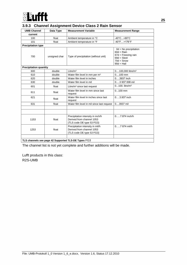
3.9.3 Channel Assignment Device Class 2 Rain Sensor
UMB Channel Data Type Measurement Variable Measurement Range
current
100 float Ambient temperature in °C -40°C...+80°C
101 float Ambient temperature in °F -40°F…+176°F
Precipitation type
700 unsigned char Type of precipitation (without unit)
0d = No precipitation 60d = Rain 67d = Freezing rain 69d = Sleet 70d = Snow 90d = Hail
Precipitation quantity
600 double Litre/m² 0....100,000 litre/m²
610 double Water film level in mm per m² 0....100 mm
620 double Water film level in inches 0….3937 Inch
630 double Water film level in mil 0….3 937 008 mil
601 float Litre/m² since last request 0...100. litre/m²
611 float Water film level in mm since last request
0...100 mm
621 float
Water film level in inches since last request
0….3.937 inch
631 float Water film level in mil since last request 0....3937 mil
1153 float
Precipitation intensity in inch/h
Derived from channel 1053
(TLS code DE type 53 FG3)
0…..7.874 inch/h
1253 float
Precipitation intensity in mil/h
Derived from channel 1053
(TLS code DE type 53 FG3)
0…..7 874 mil/h
TLS channels see page 42 Supported TLS-DE Types FG3
The channel list is not yet complete and further additions will be made.
Lufft products in this class:
R2S-UMB
26
File: UMB-Protokoll 1_0 Version 1_6_e.docx, Version 1.6, Status 17.12.2010
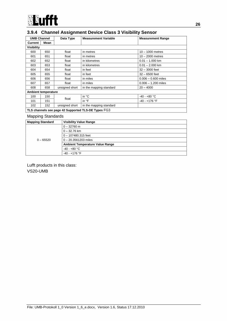
3.9.4 Channel Assignment Device Class 3 Visibility Sensor
UMB Channel Data Type Measurement Variable Measurement Range
Current Mean
Visibility
600 650 float in metres 10 – 1000 metres
601 651 float in metres 10 – 2000 metres
602 652 float in kilometres 0.01 – 1.000 km
603 653 float in kilometres 0.01 – 2.000 km
604 654 float in feet 32 – 3000 feet
605 655 float in feet 32 – 6500 feet
606 656 float in miles 0.006 – 0.600 miles
607 657 float in miles 0.006 – 1.200 miles
608 658 unsigned short in the mapping standard 20 – 4000
Ambient temperature
100 150 float
in °C -40 - +80 °C
101 151 in °F -40 - +176 °F
102 152 unsigned short in the mapping standard
TLS channels see page 42 Supported TLS-DE Types FG3
Mapping Standards
Mapping Standard Visibility Value Range
0 – 65520
0 – 32760 m
0 – 32.76 km
0 – 107480.315 feet
0 – 20.3561203 miles
Ambient Temperature Value Range
-40 - +80 °C
-40 - +176 °F
Lufft products in this class:
VS20-UMB
27
File: UMB-Protokoll 1_0 Version 1_6_e.docx, Version 1.6, Status 17.12.2010
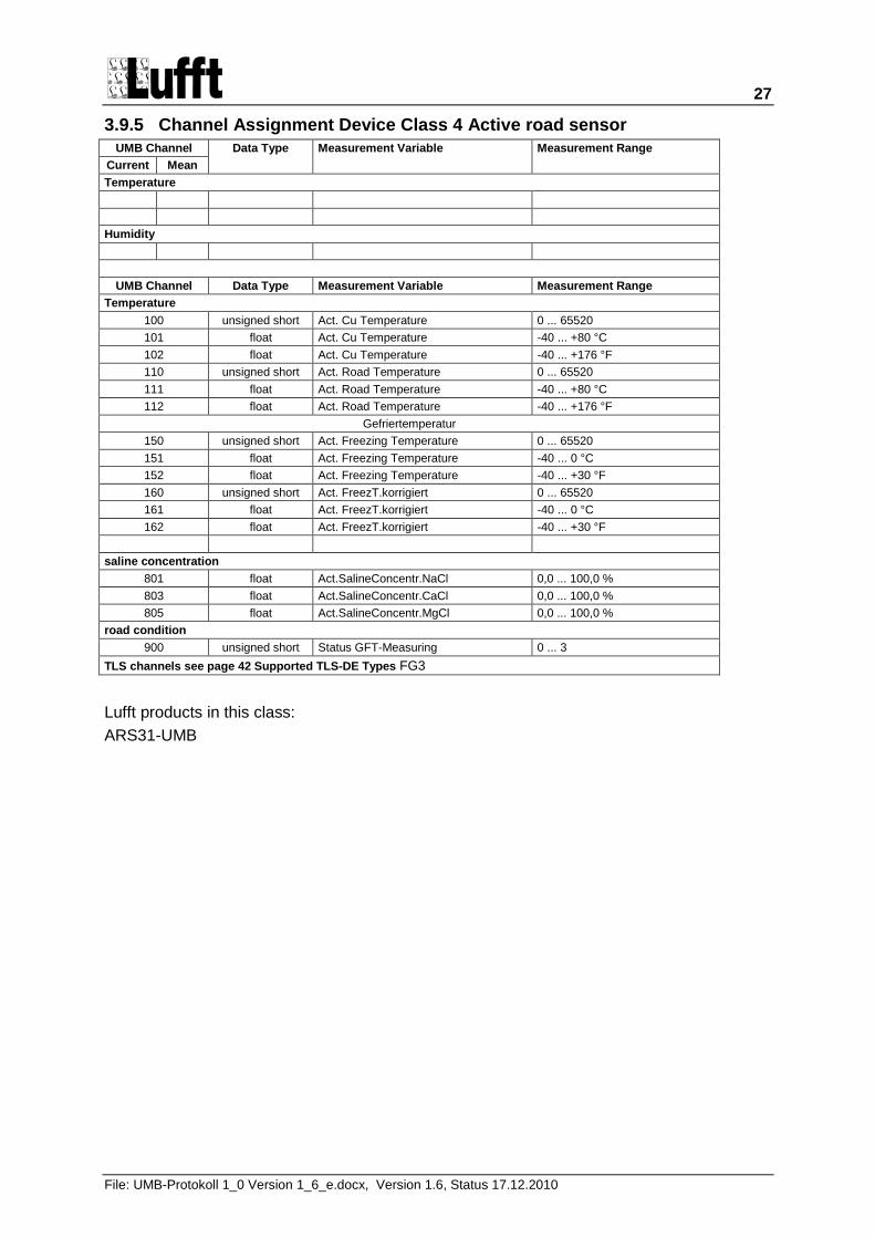
3.9.5 Channel Assignment Device Class 4 Active road sensor
UMB Channel Data Type Measurement Variable Measurement Range
Current Mean
Temperature
Humidity
UMB Channel Data Type Measurement Variable Measurement Range
Temperature
100 unsigned short Act. Cu Temperature 0 ... 65520
101 float Act. Cu Temperature -40 ... +80 °C
102 float Act. Cu Temperature -40 ... +176 °F
110 unsigned short Act. Road Temperature 0 ... 65520
111 float Act. Road Temperature -40 ... +80 °C
112 float Act. Road Temperature -40 ... +176 °F
Gefriertemperatur
150 unsigned short Act. Freezing Temperature 0 ... 65520
151 float Act. Freezing Temperature -40 ... 0 °C
152 float Act. Freezing Temperature -40 ... +30 °F
160 unsigned short Act. FreezT.korrigiert 0 ... 65520
161 float Act. FreezT.korrigiert -40 ... 0 °C
162 float Act. FreezT.korrigiert -40 ... +30 °F
saline concentration
801 float Act.SalineConcentr.NaCl 0,0 ... 100,0 %
803 float Act.SalineConcentr.CaCl 0,0 ... 100,0 %
805 float Act.SalineConcentr.MgCl 0,0 ... 100,0 %
road condition
900 unsigned short Status GFT-Measuring 0 ... 3
TLS channels see page 42 Supported TLS-DE Types FG3
Lufft products in this class:
ARS31-UMB
28
File: UMB-Protokoll 1_0 Version 1_6_e.docx, Version 1.6, Status 17.12.2010
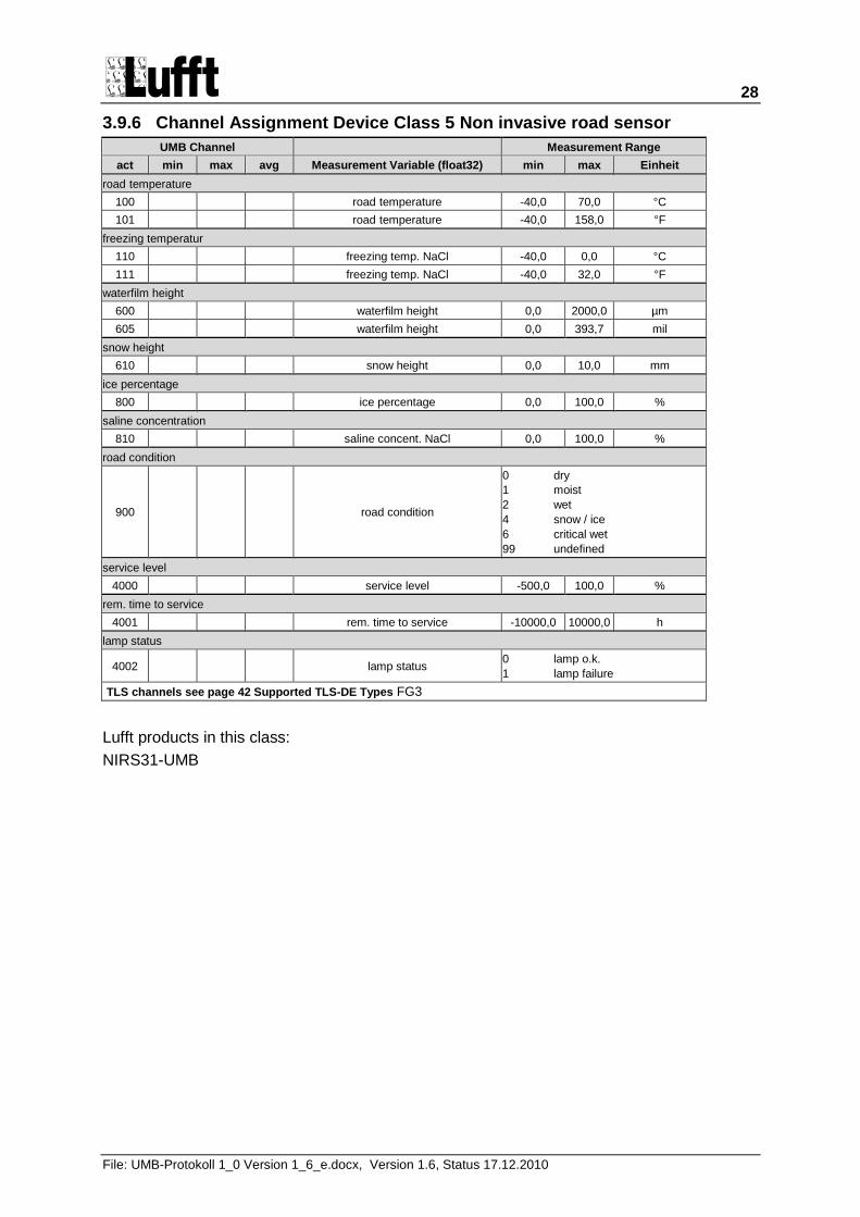
3.9.6 Channel Assignment Device Class 5 Non invasive road sensor
UMB Channel Measurement Range
act min max avg Measurement Variable (float32) min max Einheit
road temperature
100 road temperature -40,0 70,0 °C
101 road temperature -40,0 158,0 °F
freezing temperatur
110 freezing temp. NaCl -40,0 0,0 °C
111 freezing temp. NaCl -40,0 32,0 °F
waterfilm height
600 waterfilm height 0,0 2000,0 µm
605 waterfilm height 0,0 393,7 mil
snow height
610 snow height 0,0 10,0 mm
ice percentage
800 ice percentage 0,0 100,0 %
saline concentration
810 saline concent. NaCl 0,0 100,0 %
road condition
900 road condition
0 dry
1 moist
2 wet
4 snow / ice
6 critical wet
99 undefined
service level
4000 service level -500,0 100,0 %
rem. time to service
4001 rem. time to service -10000,0 10000,0 h
lamp status
4002 lamp status 0 lamp o.k.
1 lamp failure
TLS channels see page 42 Supported TLS-DE Types FG3
Lufft products in this class:
NIRS31-UMB
29
File: UMB-Protokoll 1_0 Version 1_6_e.docx, Version 1.6, Status 17.12.2010
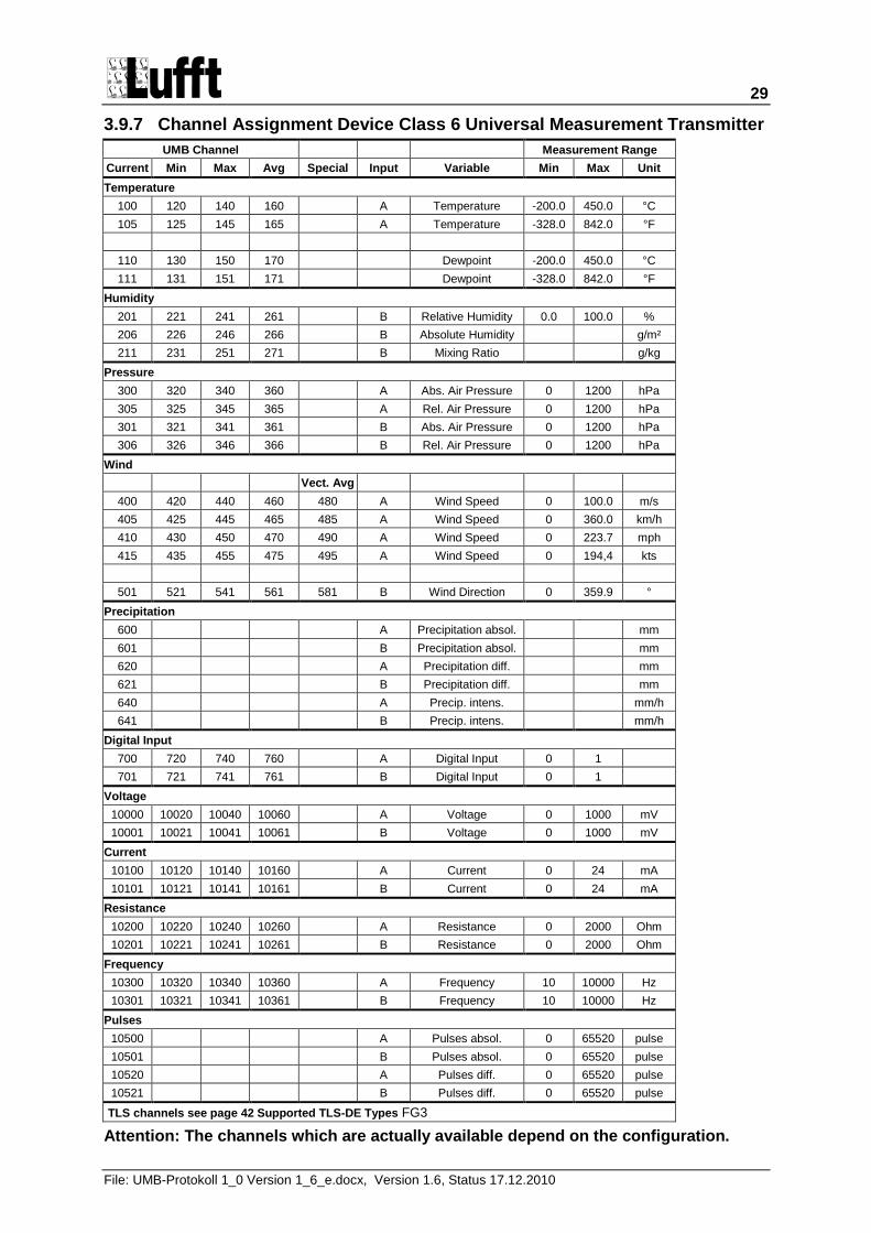
3.9.7 Channel Assignment Device Class 6 Universal Measurement Transmitter
UMB Channel Measurement Range
Current Min Max Avg Special Input Variable Min Max Unit
Temperature
100 120 140 160 A Temperature -200.0 450.0 °C
105 125 145 165 A Temperature -328.0 842.0 °F
110 130 150 170 Dewpoint -200.0 450.0 °C
111 131 151 171 Dewpoint -328.0 842.0 °F
Humidity
201 221 241 261 B Relative Humidity 0.0 100.0 %
206 226 246 266 B Absolute Humidity g/m²
211 231 251 271 B Mixing Ratio g/kg
Pressure
300 320 340 360 A Abs. Air Pressure 0 1200 hPa
305 325 345 365 A Rel. Air Pressure 0 1200 hPa
301 321 341 361 B Abs. Air Pressure 0 1200 hPa
306 326 346 366 B Rel. Air Pressure 0 1200 hPa
Wind
Vect. Avg
400 420 440 460 480 A Wind Speed 0 100.0 m/s
405 425 445 465 485 A Wind Speed 0 360.0 km/h
410 430 450 470 490 A Wind Speed 0 223.7 mph
415 435 455 475 495 A Wind Speed 0 194,4 kts
501 521 541 561 581 B Wind Direction 0 359.9 °
Precipitation
600 A Precipitation absol. mm
601 B Precipitation absol. mm
620 A Precipitation diff. mm
621 B Precipitation diff. mm
640 A Precip. intens. mm/h
641 B Precip. intens. mm/h
Digital Input
700 720 740 760 A Digital Input 0 1
701 721 741 761 B Digital Input 0 1
Voltage
10000 10020 10040 10060 A Voltage 0 1000 mV
10001 10021 10041 10061 B Voltage 0 1000 mV
Current
10100 10120 10140 10160 A Current 0 24 mA
10101 10121 10141 10161 B Current 0 24 mA
Resistance
10200 10220 10240 10260 A Resistance 0 2000 Ohm
10201 10221 10241 10261 B Resistance 0 2000 Ohm
Frequency
10300 10320 10340 10360 A Frequency 10 10000 Hz
10301 10321 10341 10361 B Frequency 10 10000 Hz
Pulses
10500 A Pulses absol. 0 65520 pulse
10501 B Pulses absol. 0 65520 pulse
10520 A Pulses diff. 0 65520 pulse
10521 B Pulses diff. 0 65520 pulse
TLS channels see page 42 Supported TLS-DE Types FG3
Attention: The channels which are actually available depend on the configuration.
30
File: UMB-Protokoll 1_0 Version 1_6_e.docx, Version 1.6, Status 17.12.2010
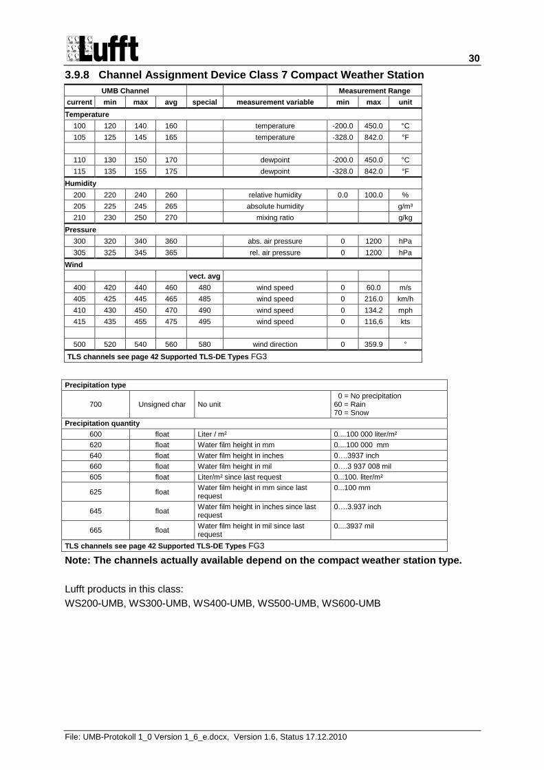
3.9.8 Channel Assignment Device Class 7 Compact Weather Station
UMB Channel Measurement Range
current min max avg special measurement variable min max unit
Temperature
100 120 140 160 temperature -200.0 450.0 °C
105 125 145 165 temperature -328.0 842.0 °F
110 130 150 170 dewpoint -200.0 450.0 °C
115 135 155 175 dewpoint -328.0 842.0 °F
Humidity
200 220 240 260 relative humidity 0.0 100.0 %
205 225 245 265 absolute humidity g/m³
210 230 250 270 mixing ratio g/kg
Pressure
300 320 340 360 abs. air pressure 0 1200 hPa
305 325 345 365 rel. air pressure 0 1200 hPa
Wind
vect. avg
400 420 440 460 480 wind speed 0 60.0 m/s
405 425 445 465 485 wind speed 0 216.0 km/h
410 430 450 470 490 wind speed 0 134.2 mph
415 435 455 475 495 wind speed 0 116,6 kts
500 520 540 560 580 wind direction 0 359.9 °
TLS channels see page 42 Supported TLS-DE Types FG3
Precipitation type
700 Unsigned char No unit 0 = No precipitation 60 = Rain 70 = Snow
Precipitation quantity
600 float Liter / m² 0....100 000 liter/m²
620 float Water film height in mm 0....100 000 mm
640 float Water film height in inches 0….3937 inch
660 float Water film height in mil 0….3 937 008 mil
605 float Liter/m² since last request 0...100. liter/m²
625 float Water film height in mm since last request
0...100 mm
645 float Water film height in inches since last request
0….3.937 inch
665 float Water film height in mil since last request
0....3937 mil
TLS channels see page 42 Supported TLS-DE Types FG3
Note: The channels actually available depend on the compact weather station type.
Lufft products in this class:
WS200-UMB, WS300-UMB, WS400-UMB, WS500-UMB, WS600-UMB
31
File: UMB-Protokoll 1_0 Version 1_6_e.docx, Version 1.6, Status 17.12.2010
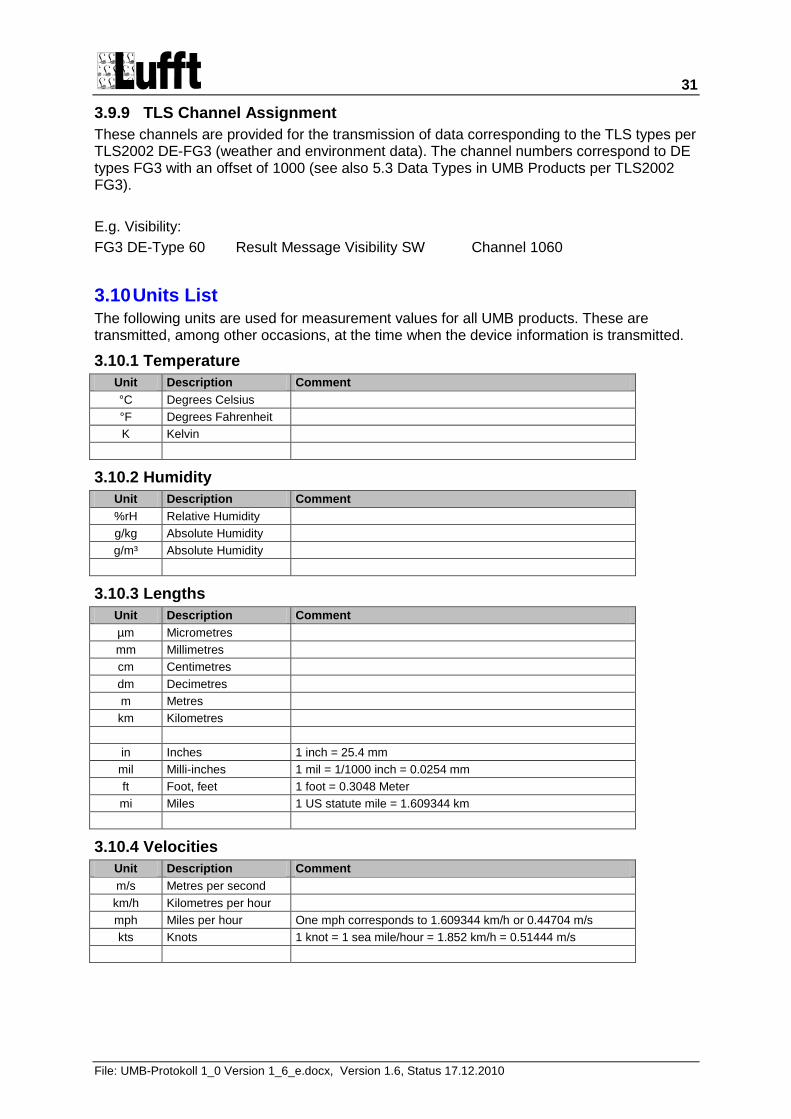
3.9.9 TLS Channel Assignment
These channels are provided for the transmission of data corresponding to the TLS types per TLS2002 DE-FG3 (weather and environment data). The channel numbers correspond to DE types FG3 with an offset of 1000 (see also 5.3 Data Types in UMB Products per TLS2002 FG3).
E.g. Visibility:
FG3 DE-Type 60 Result Message Visibility SW Channel 1060
3.10 Units List The following units are used for measurement values for all UMB products. These are transmitted, among other occasions, at the time when the device information is transmitted.
3.10.1 Temperature
Unit Description Comment
°C Degrees Celsius
°F Degrees Fahrenheit
K Kelvin
3.10.2 Humidity
Unit Description Comment
%rH Relative Humidity
g/kg Absolute Humidity
g/m³ Absolute Humidity
3.10.3 Lengths
Unit Description Comment
µm Micrometres
mm Millimetres
cm Centimetres
dm Decimetres
m Metres
km Kilometres
in Inches 1 inch = 25.4 mm
mil Milli-inches 1 mil = 1/1000 inch = 0.0254 mm
ft Foot, feet 1 foot = 0.3048 Meter
mi Miles 1 US statute mile = 1.609344 km
3.10.4 Velocities
Unit Description Comment
m/s Metres per second
km/h Kilometres per hour
mph Miles per hour One mph corresponds to 1.609344 km/h or 0.44704 m/s
kts Knots 1 knot = 1 sea mile/hour = 1.852 km/h = 0.51444 m/s
32
File: UMB-Protokoll 1_0 Version 1_6_e.docx, Version 1.6, Status 17.12.2010
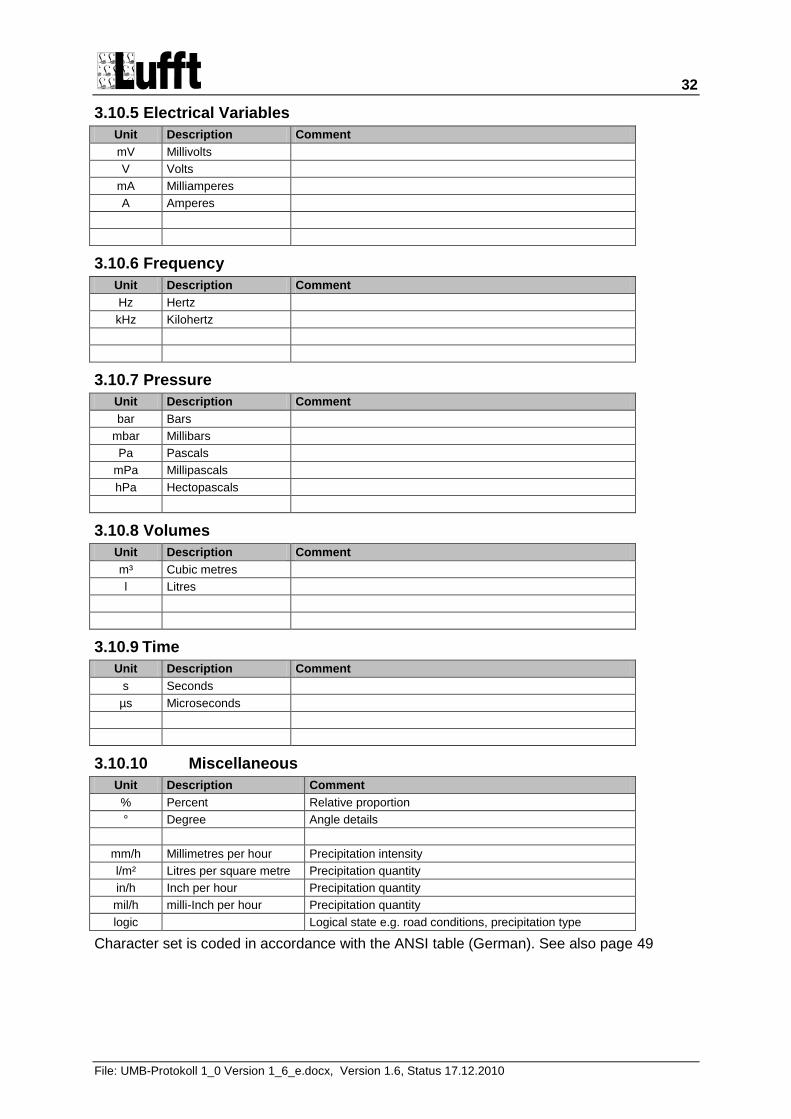
3.10.5 Electrical Variables
Unit Description Comment
mV Millivolts
V Volts
mA Milliamperes
A Amperes
3.10.6 Frequency
Unit Description Comment
Hz Hertz
kHz Kilohertz
3.10.7 Pressure
Unit Description Comment
bar Bars
mbar Millibars
Pa Pascals
mPa Millipascals
hPa Hectopascals
3.10.8 Volumes
Unit Description Comment
m³ Cubic metres
l Litres
3.10.9 Time
Unit Description Comment
s Seconds
µs Microseconds
3.10.10 Miscellaneous
Unit Description Comment
% Percent Relative proportion
° Degree Angle details
mm/h Millimetres per hour Precipitation intensity
l/m² Litres per square metre Precipitation quantity
in/h Inch per hour Precipitation quantity
mil/h milli-Inch per hour Precipitation quantity
logic Logical state e.g. road conditions, precipitation type
Character set is coded in accordance with the ANSI table (German). See also page 49
33
File: UMB-Protokoll 1_0 Version 1_6_e.docx, Version 1.6, Status 17.12.2010
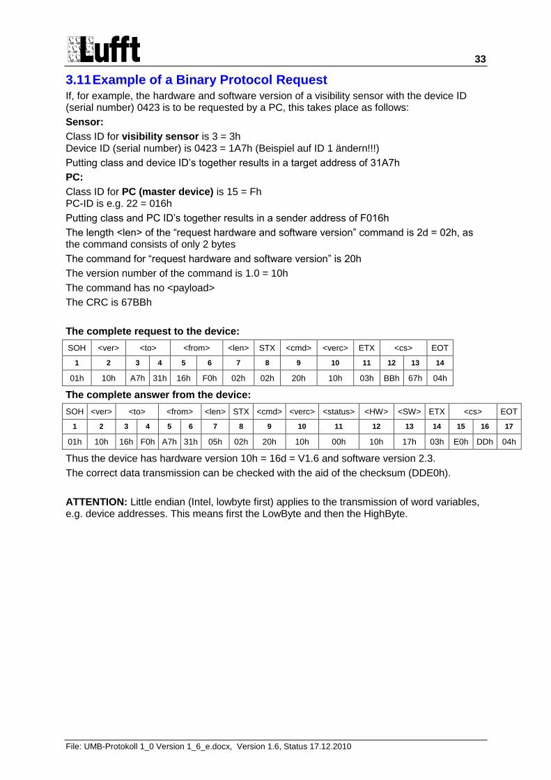
3.11 Example of a Binary Protocol Request If, for example, the hardware and software version of a visibility sensor with the device ID (serial number) 0423 is to be requested by a PC, this takes place as follows:
Sensor:
Class ID for visibility sensor is 3 = 3h Device ID (serial number) is 0423 = 1A7h (Beispiel auf ID 1 ändern!!!)
Putting class and device ID‟s together results in a target address of 31A7h
PC:
Class ID for PC (master device) is 15 = Fh PC-ID is e.g. 22 = 016h
Putting class and PC ID‟s together results in a sender address of F016h
The length <len> of the “request hardware and software version” command is 2d = 02h, as the command consists of only 2 bytes
The command for “request hardware and software version” is 20h
The version number of the command is 1.0 = 10h
The command has no <payload>
The CRC is 67BBh
The complete request to the device:
SOH <ver> <to> <from> <len> STX <cmd> <verc> ETX <cs> EOT
1 2 3 4 5 6 7 8 9 10 11 12 13 14
01h 10h A7h 31h 16h F0h 02h 02h 20h 10h 03h BBh 67h 04h
The complete answer from the device:
SOH <ver> <to> <from> <len> STX <cmd> <verc> <status> <HW> <SW> ETX <cs> EOT
1 2 3 4 5 6 7 8 9 10 11 12 13 14 15 16 17
01h 10h 16h F0h A7h 31h 05h 02h 20h 10h 00h 10h 17h 03h E0h DDh 04h
Thus the device has hardware version 10h = 16d = V1.6 and software version 2.3.
The correct data transmission can be checked with the aid of the checksum (DDE0h).
ATTENTION: Little endian (Intel, lowbyte first) applies to the transmission of word variables, e.g. device addresses. This means first the LowByte and then the HighByte.
34
File: UMB-Protokoll 1_0 Version 1_6_e.docx, Version 1.6, Status 17.12.2010
3.12 Comments about Broadcast If a device is addressed directly with class and device ID, the answer described in the command is returned.
If a device is addressed with broadcast (class or device ID „0‟), the command is NOT answered, as in the case of broadcast it must be assumed that several units are addressed simultaneously and there would otherwise be collisions.
Not all commands are broadcastable, as it makes no sense, for example, to send a measurement value request to all devices because they do not answer in the case of a broadcast. „BC‟ identifies whether a command is broadcastable. „NBC‟ stands for not broadcastable.
A sensible application of broadcast commands is, for example, the setting of date and time. In doing so, the entire network can be updated with a single telegram.
35
File: UMB-Protokoll 1_0 Version 1_6_e.docx, Version 1.6, Status 17.12.2010
4 UMB ASCII Protocol
It is possible to communicate easily with devices in the „read only‟ mode via the ASCII protocol. However, configuration can only be carried out via the binary protocol.
The ASCII protocol serves exclusively for online data requests and is not secured via a CRC. The device does not react to incomprehensible ASCII commands.
No TSL channels are available in the ASCII protocol.
4.1 Construction An ASCII command is introduced by the character „&‟ and ended with the character CR (0Dh). There is a blank character (20h) between the individual blocks in each case; represented with an underscore „_‟. Characters which represent an ASCII value are in simple quotation marks.
4.1.1 Summary of the ASCII Commands
Command Function BC RT IRS21CON VS20 R2S ANACON WSx IRS31
M Online request l
X Changes to the binary protocol s
R Triggers software reset s
D Reset with delay s
I Device information s
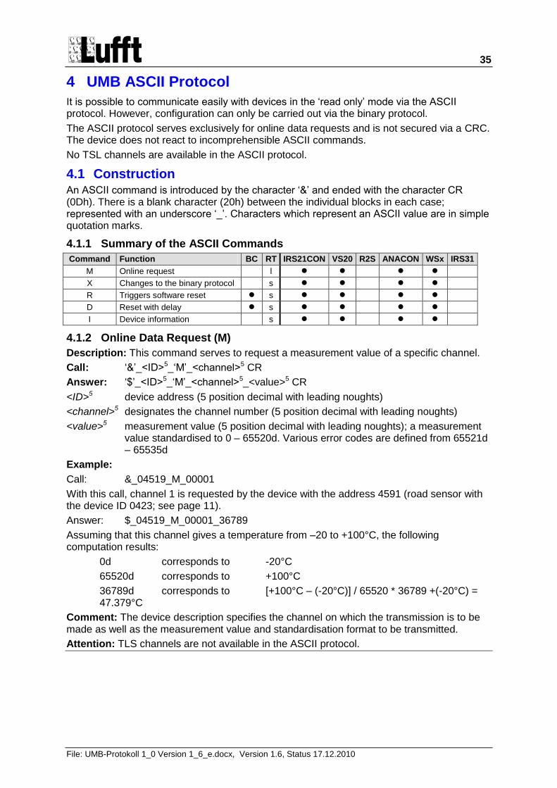
4.1.2 Online Data Request (M)
Description: This command serves to request a measurement value of a specific channel.
Call: „&‟_<ID>5_„M‟_<channel>5 CR
Answer: „$‟_<ID>5_„M‟_<channel>5_<value>5 CR
<ID>5 device address (5 position decimal with leading noughts)
<channel>5 designates the channel number (5 position decimal with leading noughts)
<value>5 measurement value (5 position decimal with leading noughts); a measurement value standardised to 0 – 65520d. Various error codes are defined from 65521d – 65535d
Example:
Call: &_04519_M_00001
With this call, channel 1 is requested by the device with the address 4591 (road sensor with the device ID 0423; see page 11).
Answer: $_04519_M_00001_36789
Assuming that this channel gives a temperature from –20 to +100°C, the following computation results:
0d corresponds to -20°C
65520d corresponds to +100°C
36789d corresponds to [+100°C – (-20°C)] / 65520 * 36789 +(-20°C) = 47.379°C
Comment: The device description specifies the channel on which the transmission is to be made as well as the measurement value and standardisation format to be transmitted.
Attention: TLS channels are not available in the ASCII protocol.
36
File: UMB-Protokoll 1_0 Version 1_6_e.docx, Version 1.6, Status 17.12.2010
4.1.3 Protocol Change (X)
Description: This command serves to switch temporarily into the binary mode.
Call: „&‟_<ID>_„X‟ CR
Answer: „$‟_<ID>_„X‟ CR
<ID>5 Device address (5 position decimal with leading noughts)
Comment: ATTENTION!! Immediately following the answer, the device can only be addressed in binary protocol. If the device is required to operate again in ASCII mode, the binary command must be given for a change of protocol to ASCII mode.
The protocol changeover is temporary!! Following a reset or device-specific timeout the device communicates again in the previously set mode. If the device is to be operated permanently in, for example, binary mode, the device specification must be changed in the EEPROM.
4.1.4 Reset / Default (R)
Description: This command serves to trigger a software reset. Alternatively, the delivered condition can be restored prior to the reset.
Call: „&‟_<ID>_„R‟_<reset> CR
Answer: „$‟_<ID>_„R‟ CR
<ID>5 Device address (5 position decimal with leading noughts)
<reset>3 010: Reset; 011: Reset with default
Comment: The answer takes place immediately before the reset.
4.1.5 Reset with Delay (D)
Description: This command serves to trigger a software reset after expiry of the delay period <delay> (e.g. for firmware update).
Call: „&‟_<ID>_„D‟_<delay> CR
Answer: „$‟_<ID>_„D‟ CR
<ID>5 Device address (5 position decimal with leading noughts)
<delay>3 Delay time in seconds (max. 255)
Comment: The answer takes place at the beginning of the delay time.
4.1.6 Device Information (I)
Description: This command serves to switch into the binary mode.
Call: „&‟_<ID>_„I‟ CR
Answer: „$‟_<ID>_„I‟_<SerNo>_<MMYY>_<Project>_<PartsList>_<PartsPlan>_<hardware> _<software>_<e2version>_<DeviceVersion> CR
<ID>5 Device address (5 position decimal with leading noughts)
<SerNo>3
<MMYY>4
<Project>4
<Stüli>3
<SPlan>3
<hardware>3
<software>3
<e2version>33
<geräteversion>5
Comment: For invalid values, the output is the corresponding number of 9.
37
File: UMB-Protokoll 1_0 Version 1_6_e.docx, Version 1.6, Status 17.12.2010
4.2 Error Codes in the ASCII Protocol Various error codes are defined from 65521d – 65535d in addition to the standardisation for the transmission of measurement values.
Codes:
<code> Define Description
65521d ASCII_UNGLTG_KANAL Invalid Channel
65522d
65523d ASCII_OVERFLOW Value Overflow
65524d ASCII_UNDERFLOW Value Underflow
65525d ASCII_DATA_ERROR
65526d ASCII_MEAS_UNABLE Device / sensor is unable to execute valid measurement due to ambient conditions
65527d
65528d
65529d
65530d
65531d
65532d
65533d
65534d ASCII_CAL_ERROR Invalid Calibration
65535d ASCII_UNBEK_ERR Unknown Error
38
File: UMB-Protokoll 1_0 Version 1_6_e.docx, Version 1.6, Status 17.12.2010
5 Appendix
5.1 CRC Calculation The CRC is calculated in accordance with the following rules:
Norm: CRC-CCITT
Polynomial: 1021h = x16 + x12 + x5 + 1 (LSB first mode)
Start value: FFFFh
(Attention! In contrast to earlier Lufft protocols, the start value for the CRC calculations in this case is not 0h but FFFFh in accordance with CCITT)
5.1.1 Example of a CRC-CCITT Calculation in C
If the CRC calculation is to be made for several bytes, the previously calculated CRC must be buffered in an unsigned short variable (which must be initialised at FFFFh at the beginning of a test sequence).
/*************************************************************************
Function: 16 bit CRC-CCITT calculation
--------------------------------------------------------------------------
Call: calc_crc(unsigned short crc_buff, unsigned char input)
--------------------------------------------------------------------------
Response: Newly calculated 16 bit CRC checksum
--------------------------------------------------------------------------
Description: Calculates the checksum for 'input' in accordance with the
CRC polynomial x^16 + x^12 + x^5 + 1.
'crc_buff' is the previously calculated checksum. This must
be set to 0xFFFF at the beginning of a test sequence.
*************************************************************************/
unsigned short calc_crc(unsigned short crc_buff, unsigned char input)
{
unsigned char i;
unsigned short x16; // we’ll use this to hold the XOR mask
for (i=0; i<8; i++)
{
// XOR current D0 and next input bit to determine x16 value
if( (crc_buff & 0x0001) ^ (input & 0x01) )
x16 = 0x8408;
else
x16 = 0x0000;
// shift crc buffer
crc_buff = crc_buff >> 1;
// XOR in the x16 value
crc_buff ^= x16;
// shift input for next iteration
input = input >> 1;
}
return(crc_buff);
}
39
File: UMB-Protokoll 1_0 Version 1_6_e.docx, Version 1.6, Status 17.12.2010
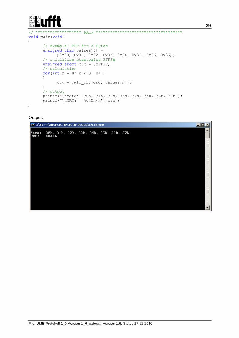
// ******************* MAIN ************************************
void main(void)
{
// example: CRC for 8 Bytes
unsigned char values[8] =
{0x30, 0x31, 0x32, 0x33, 0x34, 0x35, 0x36, 0x37};
// initialise startvalue FFFFh
unsigned short crc = 0xFFFF;
// calculation
for(int n = 0; n < 8; n++)
{
crc = calc_crc(crc, values[n]);
}
// output
printf("\ndata: 30h, 31h, 32h, 33h, 34h, 35h, 36h, 37h");
printf("\nCRC: %04Xh\n", crc);
}
Output:
40
File: UMB-Protokoll 1_0 Version 1_6_e.docx, Version 1.6, Status 17.12.2010
5.2 Automatic Readout of a Network This section describes a mechanism which makes it possible to analyse an existing network and thereby configure the master software.
5.2.1 Background
As this is a half-duplex network on RS485 basis without collision recognition, the master-slave principle must be observed. In order to scan a network, the master would have to scan the entire address space which, with more than 30,000 possible addresses, would take too long.
Instead of this, the system is configured in the way described below in order for the master software to be able to scan the network in a short period of time.
5.2.2 Necessary ID Configuration of the Sensors
The sensors are provided with device ID‟s per network and device class, beginning at 1. This also corresponds to the delivered condition. Additional sensors in a device class are provided with ID‟s in ascending order (2, 3, 4, 5 ....).
Example:
Sensors Class ID Recommended Device ID
Road sensor 1 1 1
Road sensor 2 1 2
Rain sensor 1 2 1
Rain sensor 2 2 2
Visibility sensor 1 3 1
Visibility sensor 2 3 2
Temperature/Humidity 1 4 1
Temperature/Humidity 2 4 2
Temperature/Humidity 3 4 3
NIRS 1 5 1
As the different sensors have different class ID‟s and the address is made up of class ID and device ID, each subscriber has its own address.
5.2.3 Scanning the Network
When scanning, the master begins to poll the sensors in ascending order of class and device ID. For this purpose, a command is used which is understood by each sensor; e.g. status request (26h).
The device ID is increased until no further reply is received to the status request. The class ID is then incremented, beginning again with device ID 1.
41
File: UMB-Protokoll 1_0 Version 1_6_e.docx, Version 1.6, Status 17.12.2010
5.3 Data Types in UMB Products per TLS2002 FG3 The transmission of TLS data is based on the DE block structure. The TLS output is limited to the TLS-compliant data standardisation per FG3. The answer to a measurement value request for TLS data contains the UMB channel and the measurement value. The UMB channels receive an offset of +1000 compared with DE type FG3. For multi-channel devices the offset increases by 1000 respectively.
8 bit measurement value:
Position Designation Explanation
Byte 1 Measurement value
16 bit measurement value:
Position Designation Explanation
Byte 1 Measurement value low Byte
Byte 2 Measurement value high Byte
5.3.1 Example of a TLS Measurement Value Request
A visibility measuring device is to transmit the visibility in accordance with TLS (16 bit measurement value).
DE type 60 (SW) gives UMB channel 1060 = 0424h
Call: 23h10h[<channel>²]
23h10h[24h, 04h]
Answer: 23h10h[00h, <channel>², <low byte>, <high byte>]
23h10h[00h, 24h, 04h, E8h, 03h]
High Byte = 03h; Low Byte = E8h; gives 03E8h = 1000d = 1000 metres visibility
42
File: UMB-Protokoll 1_0 Version 1_6_e.docx, Version 1.6, Status 17.12.2010
5.3.2 Supported TLS-DE Types FG3
DE Type
UMB Channel
Meaning Format Range Res. Coding
Device Class 1 Road Sensor e.g. IRS31-UMB
49 1049 Result message
Road Surface Temperature RST
16 bit -30...+80°C 0.1°C 80.0 = 800d = 0320h 0.0 = 0d = 0000h -0.1 = -1d = FFFFh -30.0 = -300d = FED4h
52 1052 Result message
Residual Salt RS
8 bit 0%...100% 1% 0% = 0d = 00h
100% = 100d = 64h
FFh = not definable
65 1065 Result message
Freezing Temperature FT
16 bit -30...0 °C 0.1°C 0.0 = 0d = 0000h
-0.1 = -1d = FFFFh
-30.0 = -300d = FED4h
67 1067 Result message Temperature at Depth 1 TD1
16 bit - 30 ... + 80 °C
0.1 °C 80.0 = 800d = 0320h
0.0 = 0d = 0000h
-0.1 = -1d = FFFFh
-30.0 = -300d = FED4h
68 1068 Result message Temperature at Depth 2 TD2
16 bit - 30 ... + 80 °C
0.1 °C see TT1
70 1070 Result message
Road Surface Condition (RSC)
8 bit 0 ... 255 see 5.3.3
72 1072 Result message
Water Film Level WFL
16 bit 0.00...10.00 mm
0.01 mm 0 = 0d = 0000h
10,00 = 1000d = 03E8h
FFFFh = not definable
Device Class 2 Rain Sensor e.g. R2S-UMB
53 1053 Result message Precipitation Intensity PI
16 bit 0 ... 200 mm/h
0.1 mm/h 0.0 = 0d = 0000h 200.0 = 2000d = 07D0h
71 1071 Result message
Precipitation Type PT
8 bit 0 ... 255 0d = No precipitation
60d = Rain (including freezing rain and sleet)
70d = Snow (including hail)
see also 5.3.4
Device Class 3 Visibility Sensor e.g. VS20-UMB
60 1060 Result message
Visibility V
16 bit 10 ... 1000 m 1 m 10 = 10d = 000Ah 1000 = 1000d = 03E8h
Device Class 4 active road sensor e.g. ARS31-UMB
Device Class 5 Non invasive road sensor e.g. NIRS31-UMB
49 1049 Ergebnismeldung Fahrbahnoberflächentemperatur
FBT
16 Bit -30 ... +80°C 0,1°C 80,0 = 800d = 0320h 0,0 = 0d = 0000h -0,1 = -1d = FFFFh -30,0 = -300d = FED4h
70 1070 Ergebnismeldung Zustand der Fahrbahnoberfläche FBZ
8 Bit 0 ... 255 0 Fahrbahn ist vollkommen Trocken (< ca. 30 ml/m2 = 0,03 mm), schnee- und eisfrei
32 Fahrbahn ist benetzt mit flüssigem Wasser bzw. wässriger Lösung. Die Menge übersteigt ca. 30 ml/m2 = 0,03 mm.
64 Fahrbahn ist bedeckt mit gefrorenem Wasser bzw. wässriger Lösung in festem Zustand.
255 Sensorik kann auf Grund der herrschenden Bedingungen Zustand nicht bestimmen
43
File: UMB-Protokoll 1_0 Version 1_6_e.docx, Version 1.6, Status 17.12.2010
72 1072 Ergebnismeldung Wasserfilmdicke WFD
16 Bit 0,00...10,00 mm
0,01 mm 0 = 0d = 0000h 10,00 = 1000d = 03E8h 65535 = 65535d = FFFFh
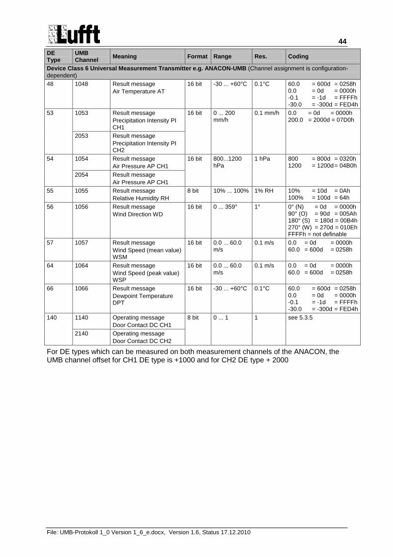
44
File: UMB-Protokoll 1_0 Version 1_6_e.docx, Version 1.6, Status 17.12.2010
DE Type
UMB Channel
Meaning Format Range Res. Coding
Device Class 6 Universal Measurement Transmitter e.g. ANACON-UMB (Channel assignment is configuration-
dependent)
48 1048 Result message
Air Temperature AT
16 bit -30 ... +60°C 0.1°C 60.0 = 600d = 0258h 0.0 = 0d = 0000h -0.1 = -1d = FFFFh -30.0 = -300d = FED4h
53 1053 Result message
Precipitation Intensity PI CH1
16 bit 0 ... 200 mm/h
0.1 mm/h 0.0 = 0d = 0000h 200.0 = 2000d = 07D0h
2053 Result message
Precipitation Intensity PI CH2
54 1054 Result message
Air Pressure AP CH1
16 bit 800...1200 hPa
1 hPa 800 = 800d = 0320h 1200 = 1200d = 04B0h
2054 Result message
Air Pressure AP CH1
55 1055 Result message
Relative Humidity RH
8 bit 10% ... 100% 1% RH 10% = 10d = 0Ah 100% = 100d = 64h
56 1056 Result message
Wind Direction WD
16 bit 0 ... 359° 1° 0° (N) = 0d = 0000h 90° (O) = 90d = 005Ah 180° (S) = 180d = 00B4h 270° (W) = 270d = 010Eh FFFFh = not definable
57 1057 Result message
Wind Speed (mean value) WSM
16 bit 0.0 ... 60.0 m/s
0.1 m/s 0.0 = 0d = 0000h 60.0 = 600d = 0258h
64 1064 Result message
Wind Speed (peak value) WSP
16 bit 0.0 ... 60.0 m/s
0.1 m/s 0.0 = 0d = 0000h 60.0 = 600d = 0258h
66 1066 Result message
Dewpoint Temperature DPT
16 bit -30 ... +60°C 0.1°C 60.0 = 600d = 0258h 0.0 = 0d = 0000h -0.1 = -1d = FFFFh -30.0 = -300d = FED4h
140 1140 Operating message
Door Contact DC CH1
8 bit 0 ... 1 1 see 5.3.5
2140 Operating message
Door Contact DC CH2
For DE types which can be measured on both measurement channels of the ANACON, the UMB channel offset for CH1 DE type is +1000 and for CH2 DE type + 2000
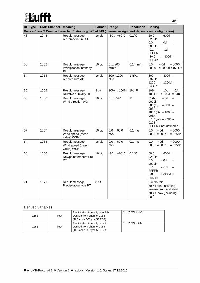
45
File: UMB-Protokoll 1_0 Version 1_6_e.docx, Version 1.6, Status 17.12.2010
DE Type UMB Channel Meaning Format Range Resolution Coding
Device Class 7 Compact Weather Station e.g. WSx-UMB (channel assignment depends on configuration)
48 1048 Result message Air temperature AT
16 bit -30 ... +60°C 0.1°C 60.0 = 600d = 0258h 0.0 = 0d = 0000h -0.1 = -1d = FFFFh -30.0 = -300d = FED4h
53 1053 Result message Precipitation intensity PI
16 bit 0 ... 200 mm/h
0.1 mm/h 0.0 = 0d = 0000h 200.0 = 2000d = 07D0h
54 1054 Result message Air pressure AP
16 bit 800...1200 hPa
1 hPa 800 = 800d = 0320h 1200 = 1200d = 04B0h
55 1055 Result message Relative humidity RH
8 bit 10% ... 100% 1% rF 10% = 10d = 0Ah 100% = 100d = 64h
56 1056 Result message Wind direction WD
16 bit 0 ... 359° 1° 0° (N) = 0d = 0000h 90° (O) = 90d = 005Ah 180° (S) = 180d = 00B4h 270° (W) = 270d = 010Eh FFFFh = not definable
57 1057 Result message Wind speed (mean value) WSM
16 bit 0.0 ... 60.0 m/s
0.1 m/s 0.0 = 0d = 0000h 60.0 = 600d = 0258h
64 1064 Result message
Wind speed (peak value) WSP
16 bit 0.0 ... 60.0 m/s
0.1 m/s 0.0 = 0d = 0000h 60.0 = 600d = 0258h
66 1066 Result message Dewpoint temperature DT
16 bit -30 ... +60°C 0.1°C 60.0 = 600d = 0258h 0.0 = 0d = 0000h -0.1 = -1d = FFFFh -30.0 = -300d = FED4h
71 1071 Result message Precipitation type PT
8 bit 0 = No rain
60 = Rain (including freezing rain and sleet)
70 = Snow (including hail)
Derived variables
1153 float
Precipitation intensity in inch/h
Derived from channel 1053
(TLS code DE type 53 FG3)
0…..7.874 inch/h
1253 float
Precipitation intensity in mil/h
Derived from channel 1053
(TLS code DE type 53 FG3)
0…..7 874 mil/h
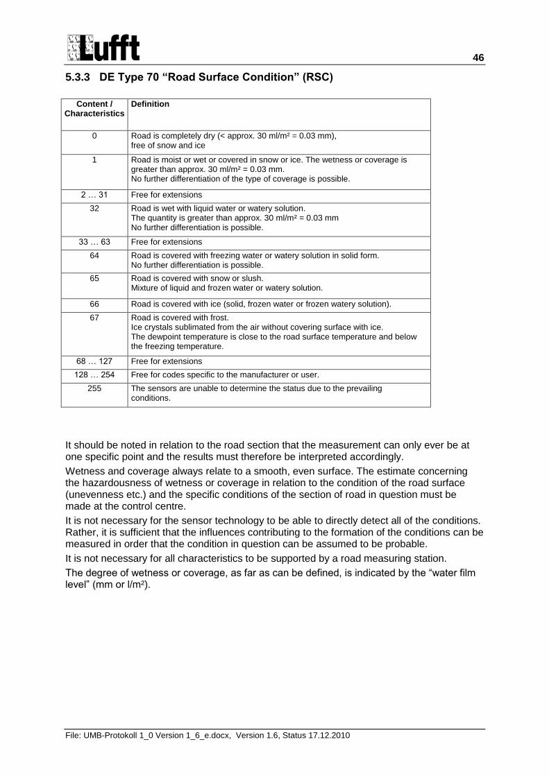
46
File: UMB-Protokoll 1_0 Version 1_6_e.docx, Version 1.6, Status 17.12.2010
5.3.3 DE Type 70 “Road Surface Condition” (RSC)
Content / Characteristics
Definition
0 Road is completely dry (< approx. 30 ml/m² = 0.03 mm), free of snow and ice
1 Road is moist or wet or covered in snow or ice. The wetness or coverage is greater than approx. 30 ml/m² = 0.03 mm. No further differentiation of the type of coverage is possible.
2 … 31 Free for extensions
32 Road is wet with liquid water or watery solution. The quantity is greater than approx. 30 ml/m² = 0.03 mm No further differentiation is possible.
33 … 63 Free for extensions
64 Road is covered with freezing water or watery solution in solid form. No further differentiation is possible.
65 Road is covered with snow or slush. Mixture of liquid and frozen water or watery solution.
66 Road is covered with ice (solid, frozen water or frozen watery solution).
67 Road is covered with frost. Ice crystals sublimated from the air without covering surface with ice. The dewpoint temperature is close to the road surface temperature and below the freezing temperature.
68 … 127 Free for extensions
128 … 254 Free for codes specific to the manufacturer or user.
255 The sensors are unable to determine the status due to the prevailing conditions.
It should be noted in relation to the road section that the measurement can only ever be at one specific point and the results must therefore be interpreted accordingly.
Wetness and coverage always relate to a smooth, even surface. The estimate concerning the hazardousness of wetness or coverage in relation to the condition of the road surface (unevenness etc.) and the specific conditions of the section of road in question must be made at the control centre.
It is not necessary for the sensor technology to be able to directly detect all of the conditions. Rather, it is sufficient that the influences contributing to the formation of the conditions can be measured in order that the condition in question can be assumed to be probable.
It is not necessary for all characteristics to be supported by a road measuring station.
The degree of wetness or coverage, as far as can be defined, is indicated by the “water film level” (mm or l/m²).
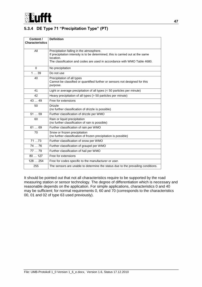
47
File: UMB-Protokoll 1_0 Version 1_6_e.docx, Version 1.6, Status 17.12.2010
5.3.4 DE Type 71 “Precipitation Type” (PT)
Content / Characteristics
Definition
All Precipitation falling in the atmosphere. If precipitation intensity is to be determined, this is carried out at the same location. The classification and codes are used in accordance with WMO Table 4680.
0 No precipitation
1 … 39 Do not use
40 Precipitation of all types Cannot be classified or quantified further or sensors not designed for this purpose.
41 Light or average precipitation of all types (< 50 particles per minute)
42 Heavy precipitation of all types (> 50 particles per minute)
43 … 49 Free for extensions
50 Drizzle (no further classification of drizzle is possible)
51 … 59 Further classification of drizzle per WMO
60 Rain or liquid precipitation (no further classification of rain is possible)
61 … 69 Further classification of rain per WMO
70 Snow or frozen precipitation (no further classification of frozen precipitation is possible)
71 …73 Further classification of snow per WMO
74 … 76 Further classification of graupel per WMO
77 … 79 Further classification of hail per WMO
80 … 127 Free for extensions
128 … 254 Free for codes specific to the manufacturer or user.
255 The sensors are unable to determine the status due to the prevailing conditions.
It should be pointed out that not all characteristics require to be supported by the road measuring station or sensor technology. The degree of differentiation which is necessary and reasonable depends on the application. For simple applications, characteristics 0 and 40 may be sufficient; for normal requirements 0, 60 and 70 (corresponds to the characteristics 00, 01 and 02 of type 63 used previously).
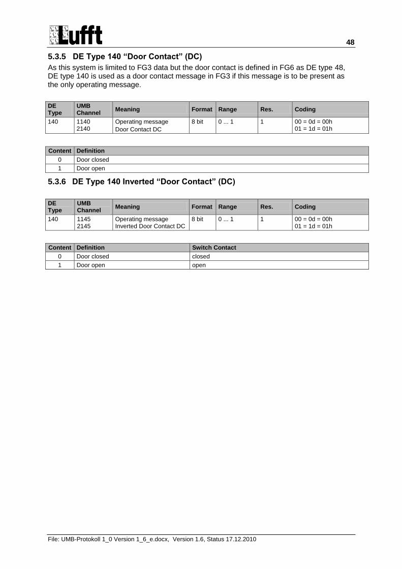
48
File: UMB-Protokoll 1_0 Version 1_6_e.docx, Version 1.6, Status 17.12.2010
5.3.5 DE Type 140 “Door Contact” (DC)
As this system is limited to FG3 data but the door contact is defined in FG6 as DE type 48, DE type 140 is used as a door contact message in FG3 if this message is to be present as the only operating message.
DE Type
UMB Channel
Meaning Format Range Res. Coding
140 1140 2140
Operating message
Door Contact DC
8 bit 0 ... 1 1 00 = 0d = 00h 01 = 1d = 01h
Content Definition
0 Door closed
1 Door open
5.3.6 DE Type 140 Inverted “Door Contact” (DC)
DE Type
UMB Channel
Meaning Format Range Res. Coding
140 1145 2145
Operating message Inverted Door Contact DC
8 bit 0 ... 1 1 00 = 0d = 00h 01 = 1d = 01h
Content Definition Switch Contact
0 Door closed closed
1 Door open open
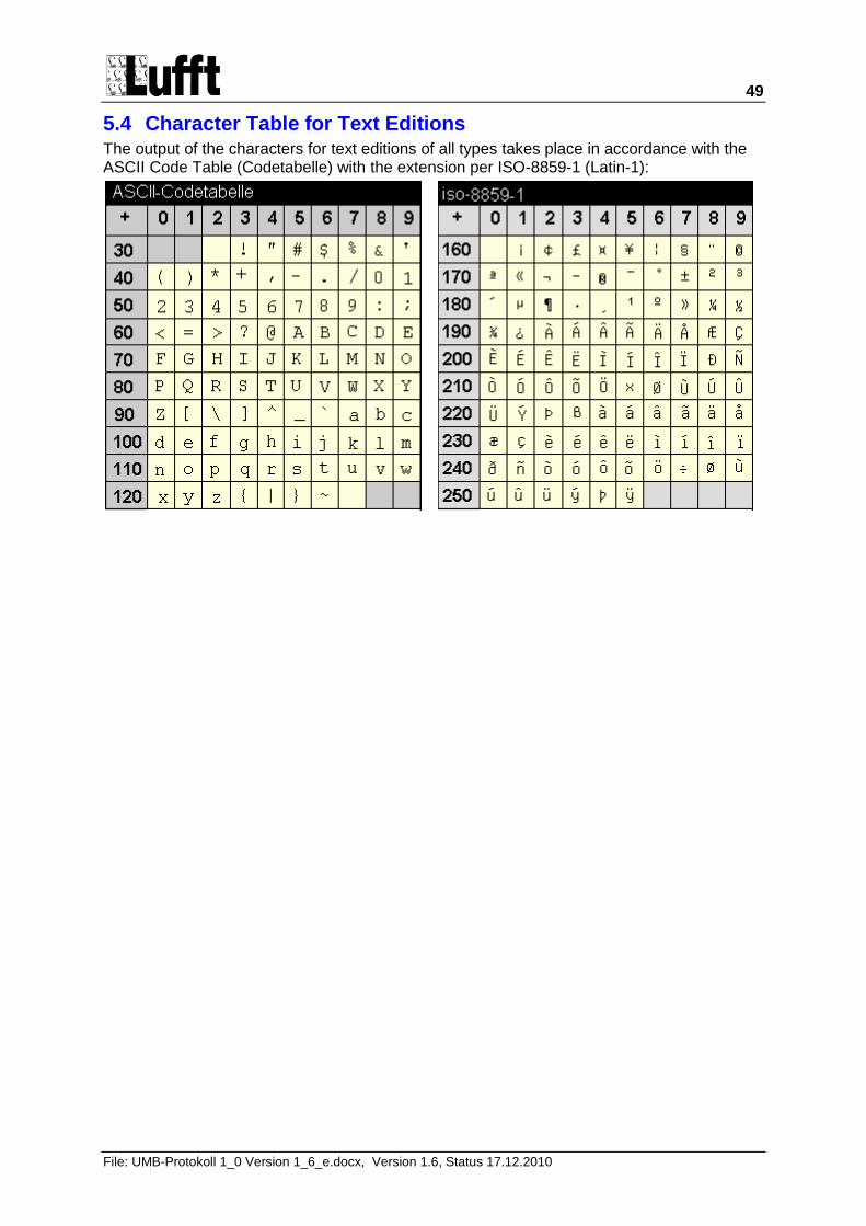
49
File: UMB-Protokoll 1_0 Version 1_6_e.docx, Version 1.6, Status 17.12.2010
5.4 Character Table for Text Editions The output of the characters for text editions of all types takes place in accordance with the ASCII Code Table (Codetabelle) with the extension per ISO-8859-1 (Latin-1):
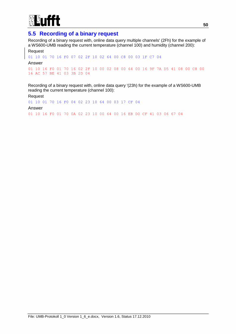
50
File: UMB-Protokoll 1_0 Version 1_6_e.docx, Version 1.6, Status 17.12.2010
5.5 Recording of a binary request Recording of a binary request with, online data query multiple channels' (2Fh) for the example of a WS600-UMB reading the current temperature (channel 100) and humidity (channel 200):
Request
01 10 01 70 16 F0 07 02 2F 10 02 64 00 C8 00 03 1F C7 04
Answer
01 10 16 F0 01 70 16 02 2F 10 00 02 08 00 64 00 16 9F 7A D5 41 08 00 C8 00
16 AC 57 BE 41 03 3B 2D 04
Recording of a binary request with, online data query '(23h) for the example of a WS600-UMB reading the current temperature (channel 100):
Request
01 10 01 70 16 F0 04 02 23 10 64 00 03 17 CF 04
Answer
01 10 16 F0 01 70 0A 02 23 10 00 64 00 16 EB D0 CF 41 03 06 67 04
Related Documents