9/26/2017 1 Ground Water and Wells Basic (Geo)Science for Sustainable a Future Dr. David Boutt UMass‐Amherst, Geosciences Department Your tasked with locating properties/land to purchase for a high yield (1000 gpm) well for the town of Sunderland, MA and Lakeside, NE on this map. Where would you put it and why? Choose 2 locations.

Welcome message from author
This document is posted to help you gain knowledge. Please leave a comment to let me know what you think about it! Share it to your friends and learn new things together.
Transcript

9/26/2017
1
Ground Water and Wells
Basic (Geo)Science for Sustainable a Future
Dr. David BouttUMass‐Amherst, Geosciences Department
Your tasked with locating properties/land to purchase for a high yield (1000 gpm)
well for the town of Sunderland, MA and Lakeside, NE on this map. Where would you put it and why? Choose 2
locations.

9/26/2017
2
What Factors are Important?
• Water Quantity• Geology/Hydrology Determines this• Impacts on Environment• Safe and Sustainable Yields
• Water Quality• Natural Water Chemistry• Filtration• Treatment
• Economic• Cost of getting water to users• Delivery and Distribution

9/26/2017
3
Globally – Groundwater provides at least 2/3 of the water to global stream discharge

9/26/2017
4
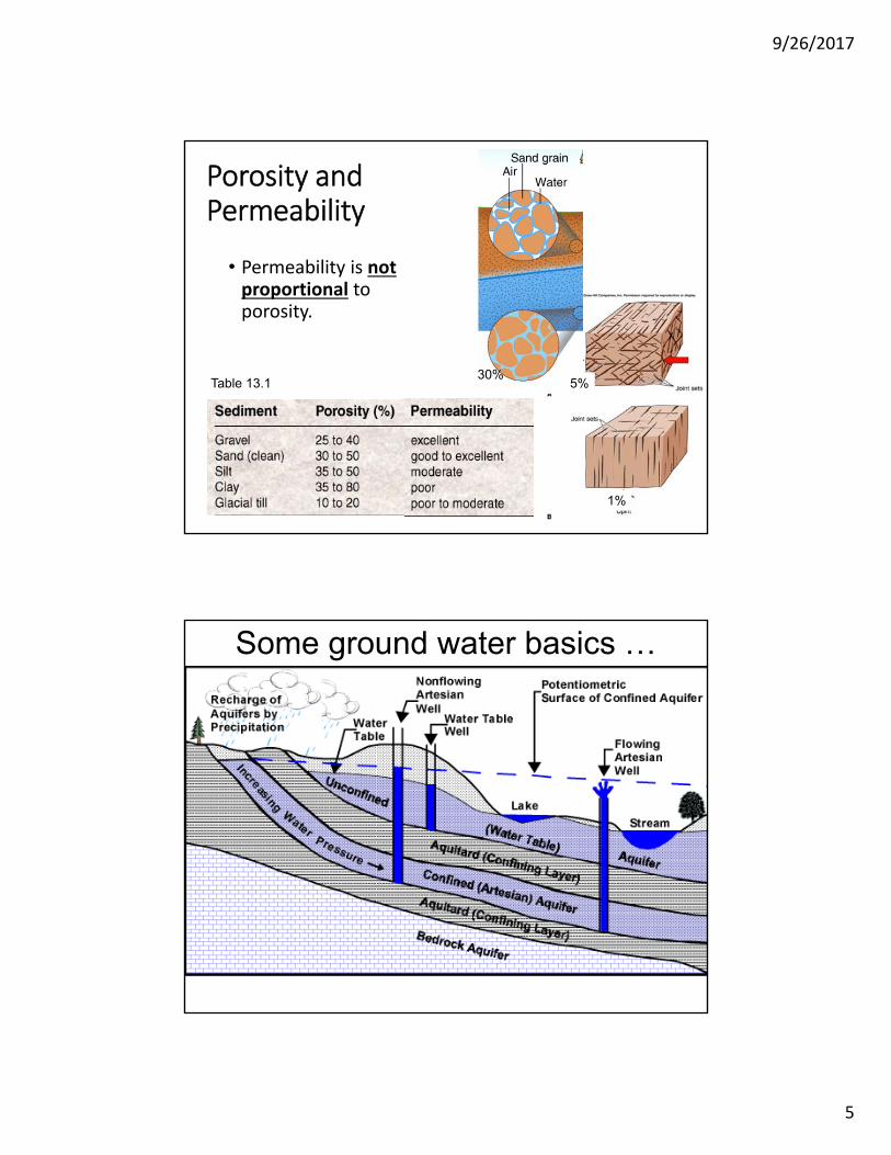
Porosity and Permeability
• Porosity: Percent of volume that is void space.
• Sediment: Determined by how tightly packed and how clean (silt and clay), (usually between 20 and 40%)
• Rock: Determined by size and number of fractures (most often very low, <5%)
1%
5%
30%
Zone of Aeration
Water Table
Saturated Zone
Porosity and Permeability
• Permeability: Ease with which water will flow through a porous material
• Sediment: Proportional to sediment size
• GravelExcellent
• SandGood
• SiltModerate
• ClayPoor
• Rock: Proportional to fracture size and number. Can be good to excellent (even with low porosity)
Excellent
Poor
Zone of Aeration
Water Table
Saturated Zone
9/26/2017
5
Porosity and Permeability
• Permeability is notproportional to porosity.
Table 13.1
1%
5%30%
Some ground water basics …

9/26/2017
6
• Infiltration• Recharges ground water
• Raises water table
• Provides water to springs, streams and wells
• Reduction of infiltration causes water table to drop
Natural Water Table Fluctuations
• Reduction of infiltration causes water table to drop
• Wells go dry
• Springs go dry
• Discharge of rivers drops
• Artificial causes• Pavement
• Drainage
Natural Water Table Fluctuations

9/26/2017
7
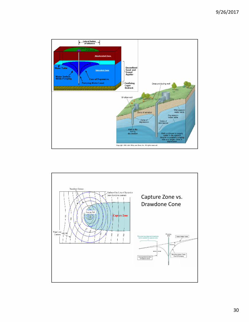
• Pumping wells• Accelerates flow near well
• May reverse ground‐water flow
• Causes water table drawdown
• Forms a cone of depression
Effects of Pumping Wells
• Pumping wells• Accelerate flow
• Reverse flow
• Cause water table drawdown
• Form cones of depression
Low river
GainingStream
GainingStream
Pumping well
Low well
Low well
Cone of Depression
Water TableDrawdown
Dry Spring
Effects of Pumping Wells

9/26/2017
8
Dry river
Dry well
Effects of Pumping Wells The picture can't be displayed.
Dry well
Dry well
LosingStream
Continued water-table drawdown May dry up
springs and wells
May reverse flow of rivers (and may contaminate aquifer)
May dry up rivers and wetlands

9/26/2017
9
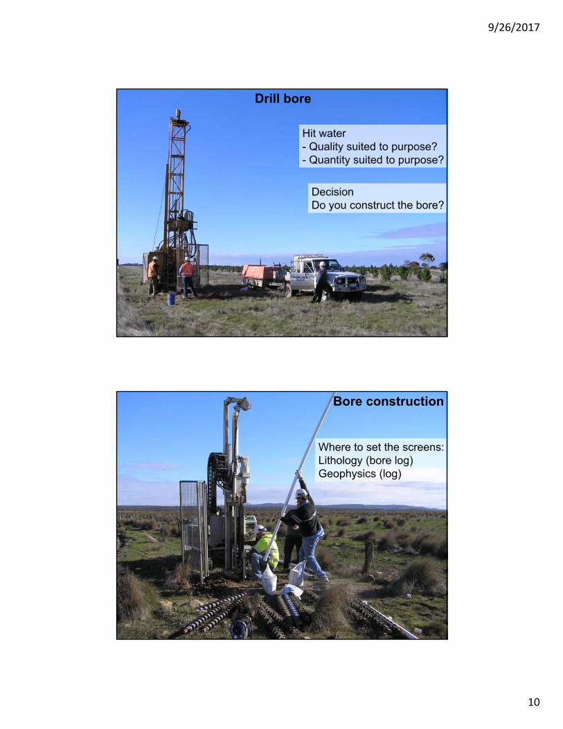
Bores are drilled for many purposes: urban water supplies, geothermal, salinity monitoring, contamination studies, rural water supply, mine dewatering, geotechnical investigations, etc., etc.
Field reconnaissance• Access for drill rigs• Infrastructure• Regulations
9/26/2017
10
Drill bore
Hit water- Quality suited to purpose?- Quantity suited to purpose?
DecisionDo you construct the bore?
Bore construction
Where to set the screens:Lithology (bore log)Geophysics (log)

9/26/2017
11
DRILLED WELLS
Casing material: Steel or PVC plastic
Installed by well drilling contractors
Much more common than driven or dug wells
Most are >50 ft. deep (avg. 125 ft.)
MOST SANITARY WELL TYPE

9/26/2017
12
Provide well that meets needs of owner
Obtain highest yield with minimal drawdown (consistent w/ aquifer capabilities)
Provide suitable quality water (potable and turbidity-free for drinking water wells)
Provide long service life (25+ years)
NEW: Minimize impacts on neighboring wells & aquatic environments
WATER WELL DRILLING METHODS
MOST COMMON: LESS COMMON:
EMERGING TECHNOLOGY
ROTARY(Mud & Air)
84%
CABLE TOOL10%
AUGER2.5%
HOLLOW ROD0.5%
OTHER2%
JETTING1%
DUAL TUBE ROTARY HORIZONTAL SONIC

9/26/2017
13
Cable ToolRotary
DRILLBIT
DRILLRODS
MUD PIT
SWIVEL
BENTONITEDRILLINGFLUID
TABLE
MUD MIXER
MUD HOSE
MASTTABLE DRIVE ROTARY
9/26/2017
14
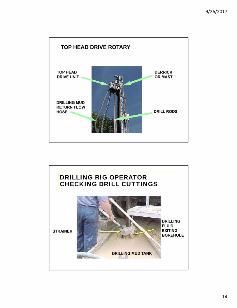
TOP HEAD DRIVE ROTARY
TOP HEAD DRIVE UNIT
DRILLING MUDRETURN FLOW HOSE
DERRICK OR MAST
DRILL RODS
DRILLING RIG OPERATORCHECKING DRILL CUTTINGS
DRILLING MUD TANK
DRILLING FLUID EXITING BOREHOLE
STRAINER

9/26/2017
15
DRILLER COMPLETING THE WATER WELL RECORD
WATER WELL & PUMPRECORD DESCRIBES:
WELL DEPTHCASING LENGTHGEOLOGIC MATERIALS
PENETRATEDSTATIC WATER LEVELPUMPING WATER LEVELPUMPING RATEGROUTING MATERIALSWELL LOCATIONPUMPING EQUIPMENTDRILLERS NAMEDRILLING RIG OPERATOR
TYPICAL ROTARY WELL CONSTRUCTIONSEQUENCE
OVERSIZEDBOREHOLE DRILLED
IDENTIFYAQUIFER
INSTALL CASING(& SCREEN)
YIELD TEST& WATER SAMPLING
WELL DEVELOPMENT
GROUTANNULARSPACE
1 2 3
6 5 4

9/26/2017
16
Bentonite Drilling Fluid- Functions -
• REMOVAL OF DRILL CUTTINGS FROM BOREHOLE
• STABILIZE THE BOREHOLE
• COOL AND LUBRICATE DRILL BIT
• CONTROL FLUID LOSS TO GEOLOGIC FORMATIONS
• DROP DRILL CUTTINGS INTO MUD PIT
• FACILITATE COLLECTION OF GEOLOGIC DATA
• SUSPEND CUTTINGS WHEN DRILLING FLUID CIRCULATION STOPS
Temporary well cap -installed between well drilling and pump hook-up
9/26/2017
17
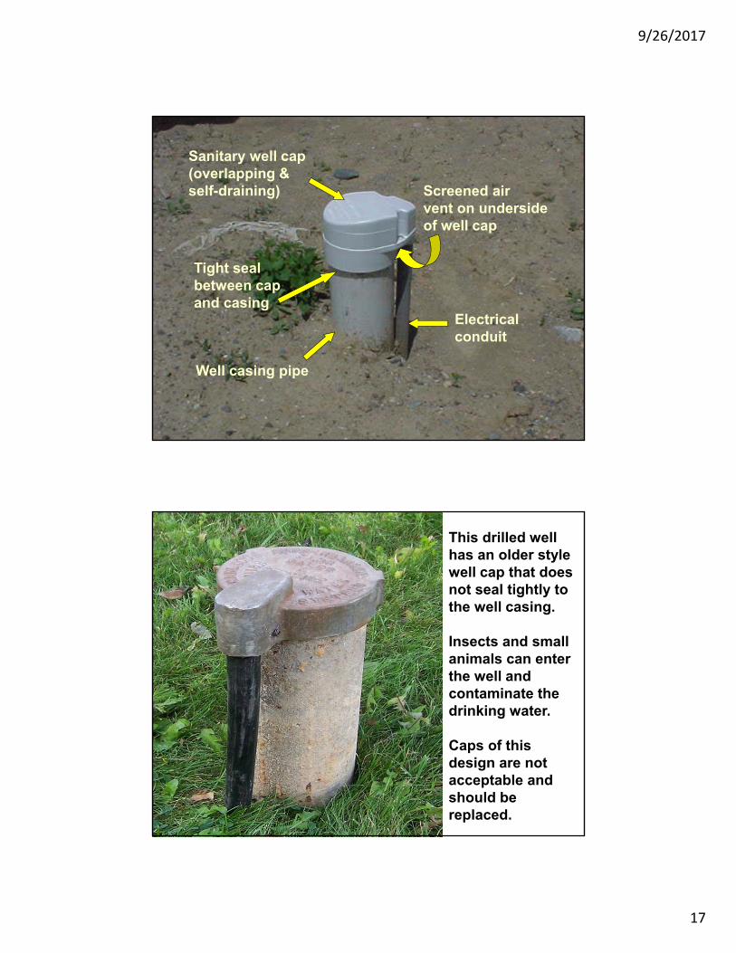
Sanitary well cap(overlapping &self-draining)
Electrical conduit
Well casing pipe
Screened airvent on undersideof well cap
Tight sealbetween cap and casing
This drilled wellhas an older stylewell cap that doesnot seal tightly to the well casing.
Insects and smallanimals can enterthe well and contaminate the drinking water.
Caps of this design are notacceptable and should be replaced.

9/26/2017
18
DRILLED WELL COMPONENTSWELL CAP or SEAL
BOREHOLE
CASING
GROUT
PACKER
SCREEN
SCREENED
WELL
DRILLED WELL COMPONENTS
WELL CAP
BOREHOLE
CASING
GROUT
BEDROCK
WELL
OPEN HOLE IN BEDROCK AQUIFER
NO CASINGIN ROCK BOREHOLE

9/26/2017
19
BOREHOLE
Vertical circular boring to reach aquifer (water bearing geologic material)
MINIMUM 2 IN. LARGER THAN CASING IF GROUTINGTHRU CASING
MINIMUM 2 7/8 IN.LARGER THAN CASING IFGROUTING WITH GROUT PIPEOUTSIDE CASING
CASINGSteel or plastic pipe installed to keep borehole wall from collapsing
Houses submersible pump or turbine bowls & drop pipe
STANDARD LENGTHS
STEEL 21 FT.
PLASTIC 20 FT.
MINIMUM 25 FT.CASING LENGTHBELOW GRADE

9/26/2017
20
WELL CAP or SEAL
Mechanical device to prevent contaminants (including insects) from entering well casing
OVERLAPPING
SEALED TIGHTLYTO CASING
SCREENEDAIR VENT
TIGHT SEAL TO ELECTRICALCONDUIT
PACKER
Device that seals space between casing & telescoped screen to keep sand out of well
(Coupling withneoprene rubber flanges)

9/26/2017
21
SCREEN
Intake device to allow water to enter well and keep sand out
Structural support of aquifer material
Wire-wrapped screen most common
WELL SCREEN
K - PACKER
SCREENBLANK

9/26/2017
22
WoundWire
Screens
Sintered HDPE
Screens
PVCScreens
9/26/2017
23
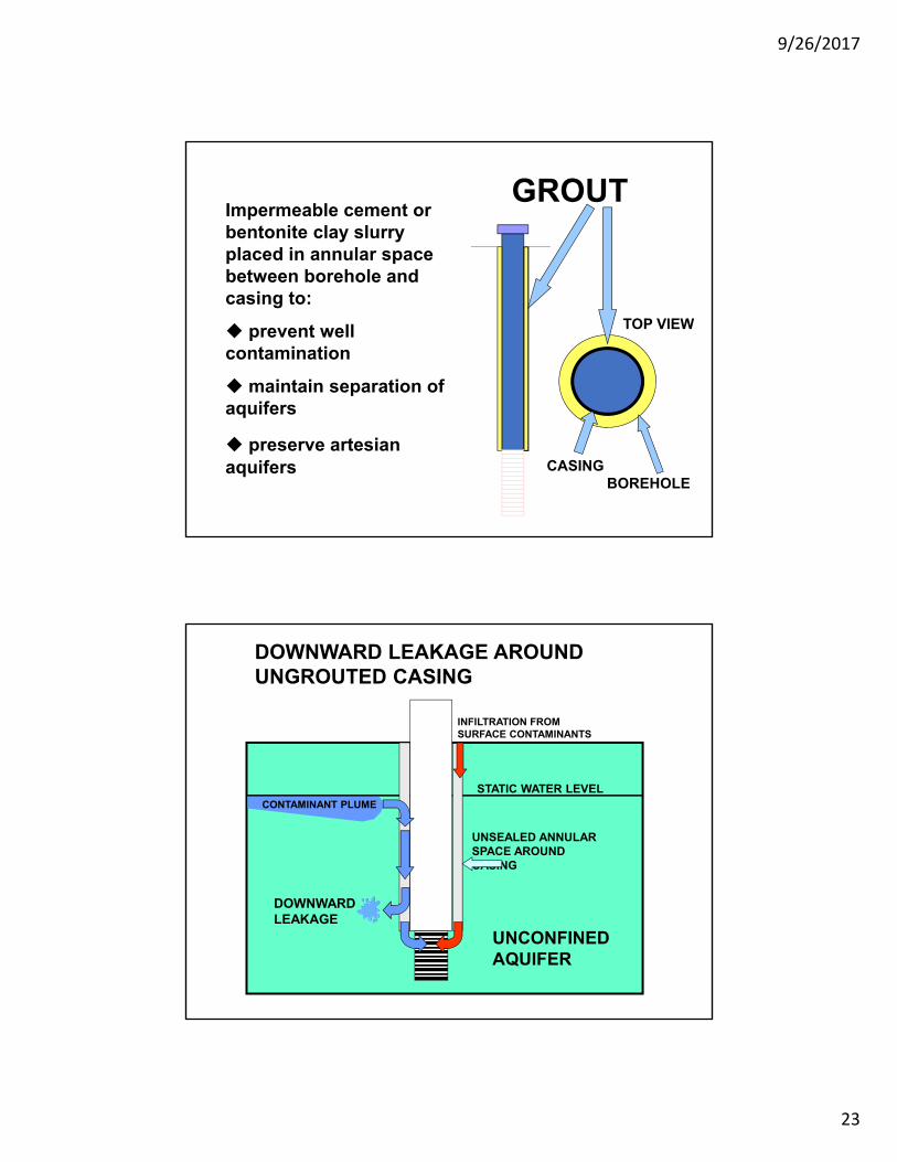
GROUTImpermeable cement or bentonite clay slurry placed in annular space between borehole and casing to:
prevent well contamination
maintain separation of aquifers
preserve artesianaquifers CASING
BOREHOLE
TOP VIEW
DOWNWARD LEAKAGE AROUND UNGROUTED CASING
UNCONFINED AQUIFER
STATIC WATER LEVEL
DOWNWARD LEAKAGE
CONTAMINANT PLUME
UNSEALED ANNULARSPACE AROUNDCASING
INFILTRATION FROM SURFACE CONTAMINANTS

9/26/2017
24
UPWARD LEAKAGE AROUND UNGROUTED CASING
CONFINED AQUIFER
UNCONFINED AQUIFER
CONFINING LAYER
STATIC WATER LEVEL
UPWARD LEAKAGE
(Artesian Condition)
BENEFITS OF WELL GROUTING
• PREVENT CONTAMINANT MIGRATION FROM SURFACE (Keeps surface runoff from moving downward along well casing)
• SEAL OFF POOR QUALITY AQUIFERS (Prevents mixing of water from different aquifers)
• PRESERVE ARTESIAN AQUIFER PROPERTIES
• ADDED SEALING OF CASING JOINTS

9/26/2017
25
BEDROCKWELL DETAILS
BEDROCK BOREHOLE(SMALLER DIAMETERTHAN CASING)
SHALE TRAPOR
SHALE PACKER
PREVENTS GROUTSPILLAGE INTOBEDROCK BOREHOLE
BETTER SEAL AT BEDROCK INTERFACE
CASING PIPE
GROUT
TOP OF BEDROCK
Bore Development

9/26/2017
26
Electric submersible pumps
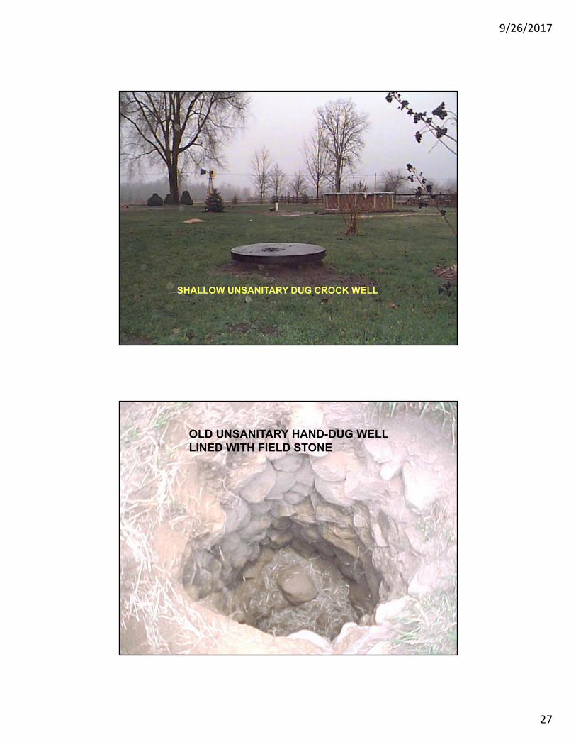
DUG WELLS Large diameter (18-48 in.)
Found in low yield areas
Casing material - concrete crocks w/ loose joints
Older wells: stones, brick-lined
Water enters well through loose casing joints
9/26/2017
27
SHALLOW UNSANITARY DUG CROCK WELL
OLD UNSANITARY HAND-DUG WELL LINED WITH FIELD STONE

9/26/2017
28
DUG WELLS Older wells - hand dug
Now installed (on very limited basis) w/ bucket augers (backhoes – phased out)
Low well yield - storage in casing (100’s of gallons)
HIGHLY VULNERABLE TO CONTAMINATION
CDC Findings on Dug Wells
• Dug/bored wells had a positive coliform bacteria rate of about 85%
• Wells with brick, concrete or wood casing (dug wells) had coliform positive rates of 60 – 90 %
From A Survey of the Presence of Contaminants in Water From Private Wells in Nine Midwestern States, Atlanta, Georgia, U.S.Dept. of Health and Human Services, Public Health Service, Centers for Disease Control, 1996

9/26/2017
29
Some useful terms to know: Cone of depression Drawdown Radius of influence Specific capacity
9/26/2017
30
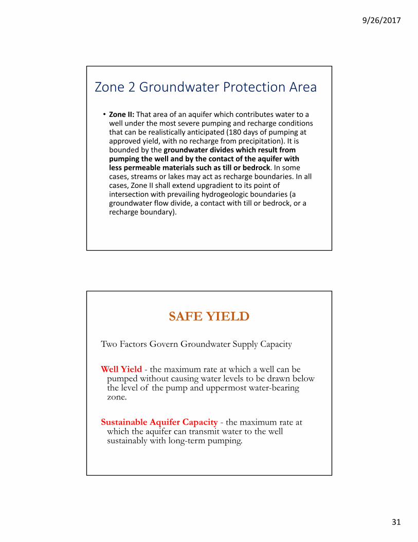
Capture Zone vs. Drawdone Cone
9/26/2017
31
Zone 2 Groundwater Protection Area
• Zone II: That area of an aquifer which contributes water to a well under the most severe pumping and recharge conditions that can be realistically anticipated (180 days of pumping at approved yield, with no recharge from precipitation). It is bounded by the groundwater divides which result from pumping the well and by the contact of the aquifer with less permeable materials such as till or bedrock. In some cases, streams or lakes may act as recharge boundaries. In all cases, Zone II shall extend upgradient to its point of intersection with prevailing hydrogeologic boundaries (a groundwater flow divide, a contact with till or bedrock, or a recharge boundary).
SAFE YIELD
Two Factors Govern Groundwater Supply Capacity
Well Yield - the maximum rate at which a well can be pumped without causing water levels to be drawn below the level of the pump and uppermost water-bearing zone.
Sustainable Aquifer Capacity - the maximum rate at which the aquifer can transmit water to the well sustainably with long-term pumping.

9/26/2017
32
Factors Influencing Safe Yield
Average Annual Precipitation
- Watershed Area
- Recharge Rate
- Presence of Surface Water Bodies
- Aquifer Parameters (transmissivity, storativity)
- Competing Water Demands
Knowledge of these variables, combined with a well-formulated conceptual model, can support an initial estimate of likely Safe Yield of a well.
180-DAY PROJECTION OF WATER LEVEL TREND
End-of-Test Drawdown trend projected to a period of 180 days (259,200 minutes). Projected water level is 23.5 feet below sea level, assuming no boundaries. Top of water-bearing zone in this gravel-pack well is around 10 feet below sea level, so we would expect trend to steepen as aquifer is gradually dewatered and saturated thickness decreases. Unless some source of recharge is nearby, the yield of 64.8 gpm is probably not sustainable. Data from Antigua.
9/26/2017
33
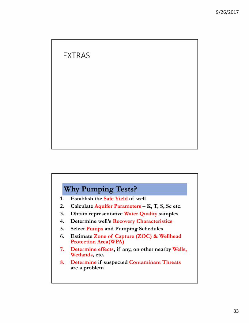
EXTRAS
Why Pumping Tests?1. Establish the Safe Yield of well2. Calculate Aquifer Parameters – K, T, S, Sc etc.3. Obtain representative Water Quality samples4. Determine well’s Recovery Characteristics5. Select Pumps and Pumping Schedules6. Estimate Zone of Capture (ZOC) & Wellhead
Protection Area(WPA)7. Determine effects, if any, on other nearby Wells,
Wetlands, etc.8. Determine if suspected Contaminant Threats
are a problem

9/26/2017
34
Types of Pump TestsStep Test• Performed two or more days prior to the start of constant rate tests (allow for complete water level
recovery to occur prior to start up of Constant Rate Test )
• Test usually includes from three to eight equal time pumping steps of from 90-120 minutes duration while incrementally increasing the discharge rate after each Step and keeping discharge rate constant during each step.
• Very important to measure drawdown frequently for bedrock wells to determine fracture dewatering depth ( or install recording pressure transducer)
• May be the only real opportunity to overstress the well before putting on-line
• Analyze step test data and conduct step tests using formation and fracture location data
Constant Rate Test • Pumping rate fixed for duration of test – Testing continues for several days until the well water levels
have reached complete stabilization or log stabilization
• Aquifer water levels, barometric pressure, rainfall and ambient monitoring well data collected prior to, during and after pumping for specified period of time.
Pumping Test Set up-Trinidad
9/26/2017
35
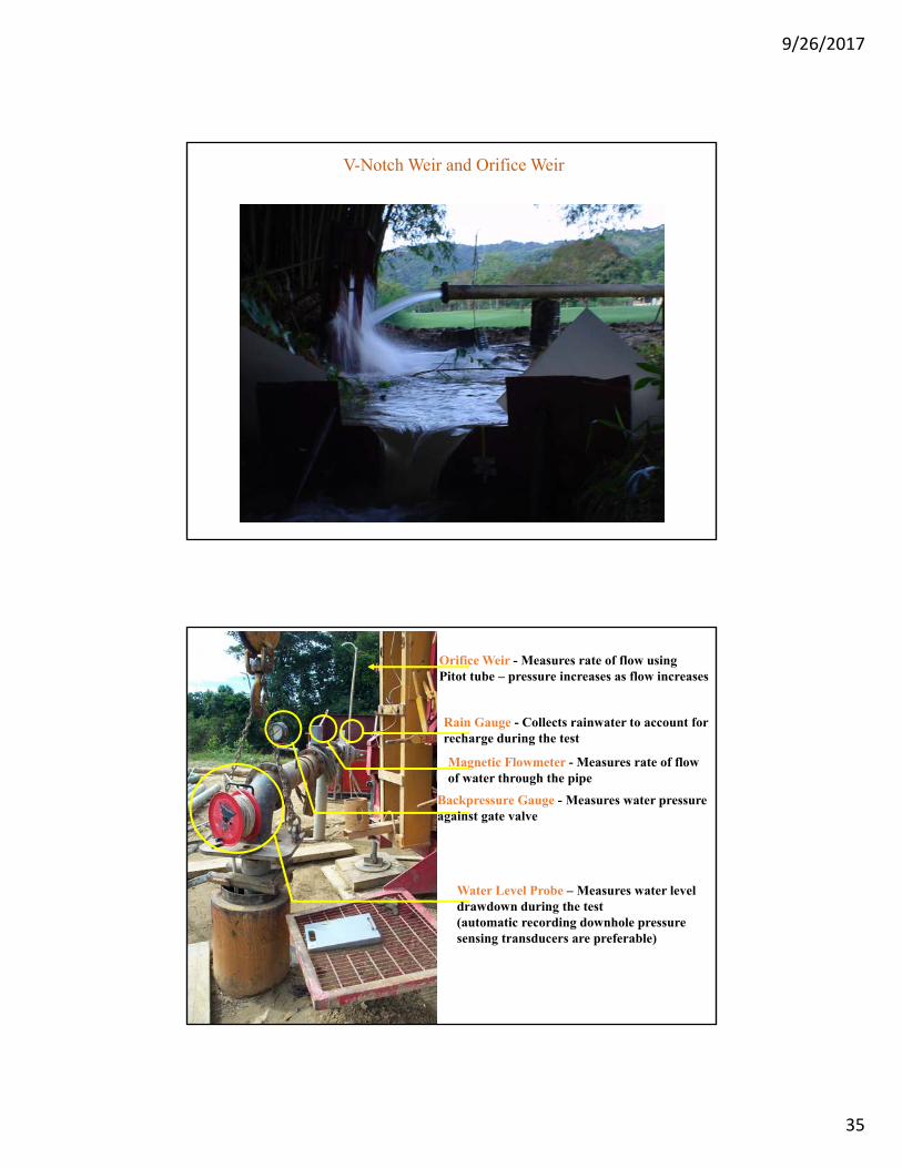
V-Notch Weir and Orifice Weir
Orifice Weir - Measures rate of flow using Pitot tube – pressure increases as flow increases
Magnetic Flowmeter - Measures rate of flow of water through the pipe
Backpressure Gauge - Measures water pressure against gate valve
Water Level Probe – Measures water level drawdown during the test(automatic recording downhole pressure sensing transducers are preferable)
Rain Gauge - Collects rainwater to account for recharge during the test

9/26/2017
36
At Constant-Rate-Pump Test Startup……• Prior to start of the test, open the flow (gate) valve to achieve the desired
flow for the first step as quickly as possible.
• One person should be monitoring pump discharge while another measures water levels. ( If possible, purchase recording pressure transducers to make life easy)
• During the first few minutes of the test, drawdown may occur rapidly so it is important to check discharge frequently, and also calibrate discharge with a bucket and stopwatch.
If manually taking measurements use the following minimum recording schedule.
• First minute - at 30 and 60 seconds
• 1- 10 minutes - every minute
• 10 - 30 minutes - every 2 to 4 minutes
• 30 - 60 minutes - every 5 to 10 minutes
• After 60 minutes - every hour for first 24 hours
• For remainder of test period – 4 to 8 times per day
More frequently at end of test period ...OR....Set Automatic reading transducers to record at 10 minute intervals throughout the remainder of the test period)
ZEROING IN ON SAFE YIELD
What if the pumping rate used for the constant rate test produces a 180-day water level projection that is too deep, or too shallow?
Two key aquifer parameters, transmissivity and storativity, can be calculated using test data.
Parameter calculations are made using "analytical methods" (e.g., Theis or Jacob).
Same methods are then used to back-calculate the precise pumping rate corresponding with maximum allowable drawdown amount.
For hydrogeologically complex settings, or those involving higher-capacity water supplies, numerical flow models are frequently used to obtain more accurate and dependable assessments of safe yield.

9/26/2017
37
600 US gpm Constant Rate DataWater Level vs. Time
Fractured Bedrock Well- Constant Rate Test -255 GPMRound Hill, VA – circa 1985

9/26/2017
38
320+ GPM Fractured Bedrock WellConstant Rate Test, 1982
Seabrook Water Supply Well #3 - Seabrook, NH
Water levels in this well showed a relatively log-linear rate of decline until pumping had been underway for nearly 200 minutes. A new, shallower declining trend develops at that point, suggesting that a recharge boundary has been encountered.
Semilog Graph, 750-GPM Constant Rate TestPutnam, CT
This well looked like it might stabilize until it had been pumped for about 2000 minutes. Then, perhaps after some volume of local storage in the fractured bedrock aquifer had been exhausted, water levels resumed a steep decline.

9/26/2017
39
CAN YOU TRUST THE TREND?
Using the prevailing end-of-test water level trend to project the 180-day water level carries the assumption that the trend would persist unchanged if pumping continued. A good assumption? Possibly, but with Exceptions
1. RECHARGE BOUNDARY ENCOUNTERED BEFORE END OF TEST
If drawdown "stops" before the end of the test, and the final trend of the water level data is horizontal, the cone of depression has expanded far enough to encounter a recharge boundary with recharge sufficient to exactly balance the withdrawal rate.
If the stabilized water level is far enough above the pump and highest water-bearing zones to give the desired margin of safety, the pumping rate is sustainable.
CAN YOU TRUST THE TREND?2. RECHARGE BOUNDARY NOT ENCOUNTERED BEFORE END
OF TEST
If the end-of-test water level trend is a decline, possibility remains that one or more boundaries would have been encountered if pumping continued-- either recharge (producing shallower rate of decline or water level stabilization) or barrier (producing steepening of water level decline, and more rapid-than-expected consumption of available drawdown).
There's nothing in the pumping test data to predict when the next boundary might be encountered, so we fall back on what the conceptual model can tell us, and we err on the side of conservatism in estimating the well's safe yield to account for the added uncertainty.

9/26/2017
40
Aquifer Management
Capture Zone vs. Drawdone Cone
9/26/2017
41
Technical Base to Groundwater Management
Identification of the recharge and discharge areas and connectivity of the aquifer system Characterization of hydrogeologic properties of aquifers,
water quality, hydraulic heads and flow of groundwater Development of mathematical models of hydrogeologic
behavior and risk analysis (vulnerability on local and regional scale)A network and information system that integrates groundwater
date base (quantity and quality parameters, well characteristics, use and protection)
Related Documents