556 www.sensopart.com Ultrasonic sensors may be a useful alternative where optical sen- sors come up against their physical limits. This applies, for exam- ple, for objects with uneven surfaces or under difficult ambient conditions, or with highly transparent media as well as moving, highly reflective liquid surfaces. Typical uses of ultrasonic sensors are therefore checking the presence of highly transparent foils and measuring the filling levels in liquid containers. A major ad- vantage of ultrasonic sensors is the absolutely reliable back- ground suppression resulting from their sound time-of-flight measurement principle. The new ultrasonic sensor with soundpipe (UT 20S), in its very compact cubic housing, is a special product variant. As a result of its narrow sound cone, it allows the detection of objects even through the smallest of openings and drilled holes with a diame- ter of less than 5 mm. This makes it ideal for special applications, such as level measurement in the wells of microplates in medical analysis systems or for scanning circuit boards in the electronics industry. The ultrasonic sensors of the UMT 30 series are real multifunc- tional artists. A three-digit display makes all sensor settings easy for users. The add-on menu with numerous supplementary func- tions, e.g. the synchronisation of several sensors or multiplex op- eration, in which several sensors measure after one another in as- cending order, allows the UMT 30 to offer extremely flexible use for a wide range of applications. Ultrasonic sensors Reliable on almost all surfaces UT 20 from Page 560 UT 20-S – miniature ultrasonic sensors with soundpipe • Reliable detection through the smallest of openings and drilled holes • Ideal for measuring filling levels of microplates and for scanning circuit boards • Small housings for installation in smallest of spaces • PNP, NPN or analogue output options >> Page 560 UT 20 – miniature ultrasonic sensors • Small housing for installation in smallest of spaces • High scanning distances of up to 700 mm with with compact miniature housing • PNP, NPN or analogue output options >> Page 564 UT 12 from Page 576 UT 12 – M12 ultrasonic sensors • Robust metal housings for harsh operating conditions • Simple installation with universal M12 standard thread • Simple sensor setting via control input >> Page 576 UT/UM 18 from Page 580 UT/UM 18 – M18 ultrasonic sensors • Robust brass or stainless steel housings for harsh operating conditions • Simple installation with universal M18 standard thread • Simple sensor setting via control input >> Page 580 Deflection mirrors are available for deflecting the sound beam when machine space is limited. The UT 20-S measuring levels in microplate wells.

Welcome message from author
This document is posted to help you gain knowledge. Please leave a comment to let me know what you think about it! Share it to your friends and learn new things together.
Transcript
556 www.sensopart.com
Ultrasonic sensors may be a useful alternative where optical sen-sors come up against their physical limits. This applies, for exam-ple, for objects with uneven surfaces or under difficult ambient conditions, or with highly transparent media as well as moving, highly reflective liquid surfaces. Typical uses of ultrasonic sensors are therefore checking the presence of highly transparent foils and measuring the filling levels in liquid containers. A major ad-vantage of ultrasonic sensors is the absolutely reliable back-ground suppression resulting from their sound time-of-flight measurement principle.
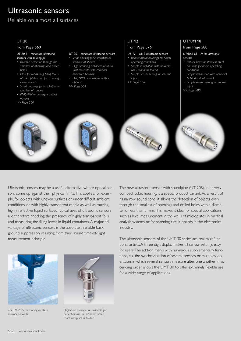
The new ultrasonic sensor with soundpipe (UT 20 S), in its very compact cubic housing, is a special product variant. As a result of its narrow sound cone, it allows the detection of objects even through the smallest of openings and drilled holes with a diame-ter of less than 5 mm. This makes it ideal for special applications, such as level measurement in the wells of microplates in medical analysis systems or for scanning circuit boards in the electronics industry.
The ultrasonic sensors of the UMT 30 series are real multifunc-tional artists. A three-digit display makes all sensor settings easy for users. The add-on menu with numerous supplementary func-tions, e.g. the synchronisation of several sensors or multiplex op-eration, in which several sensors measure after one another in as-cending order, allows the UMT 30 to offer extremely flexible use for a wide range of applications.
Ultrasonic sensorsReliable on almost all surfaces
UT 20
from Page 560
UT 20-S – miniature ultrasonic sensors with soundpipe• Reliable detection through the
smallest of openings and drilled holes
• Ideal for measuring filling levels of microplates and for scanning circuit boards
• Small housings for installation in smallest of spaces
• PNP, NPN or analogue output options
>> Page 560
UT 20 – miniature ultrasonic sensors• Small housing for installation in
smallest of spaces• High scanning distances of up to
700 mm with with compact miniature housing
• PNP, NPN or analogue output options
>> Page 564
UT 12
from Page 576
UT 12 – M12 ultrasonic sensors• Robust metal housings for harsh
operating conditions • Simple installation with universal
M12 standard thread • Simple sensor setting via control
input>> Page 576
UT/UM 18
from Page 580
UT/UM 18 – M18 ultrasonic sensors• Robust brass or stainless steel
housings for harsh operating conditions
• Simple installation with universal M18 standard thread
• Simple sensor setting via control input
>> Page 580
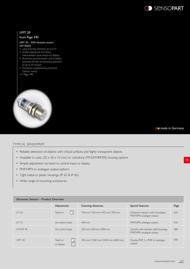
Deflection mirrors are available for deflecting the sound beam when machine space is limited.
The UT 20-S measuring levels in microplate wells.
557www.sensopart.com
11
560
576
580
590
UMT 30
from Page 590
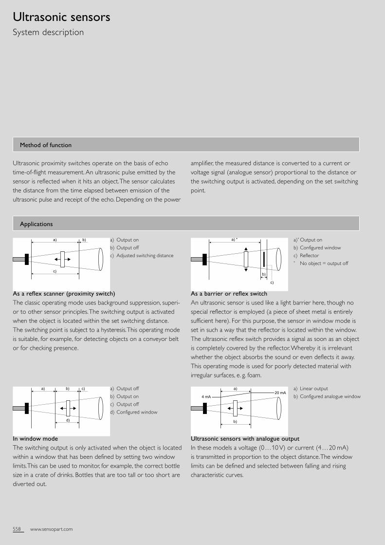
UMT 30 – M30 ultrasonic sensors with display• Long scanning distances up to 6 m• Simple adjustment and direct
measurement value output via display• Automatic synchronisation and multiplex
operation for the simultaneous operation of up to 10 sensors
• Numerous supplementary functions (add-on menu)
>> Page 590
TYPICAL SENSOPART
• Reliable detection of objects with critical surfaces and highly transparent objects
• Available in cubic (32 x 20 x 12 mm) or cylindrical (M12/M18/M30) housing options
• Simple adjustment via teach-in, control input or display
• PNP, NPN or analogue output options
• Tight metal or plastic housings (IP 67 & IP 65)
• Wide range of mounting accessories
Ultrasonic Sensors – Product Overview
Adjustment Scanning distances Special features Page
UT 20 Teach-in 140 mm / 150 mm / 240 mm / 700 mm Ultrasonic sensors with soundpipe, PNP, NPN, analogue output
UT 12 Via control input 400 mm PNP, NPN, analogue output
UT/UM 18 Via control input 250 mm / 300 mm / 800 mm Variants with stainless steel housings, PNP, NPN, analogue output
UMT 30 Teach-in or display
Display
1 2 3 4
350 mm / 1300 mm / 3400 mm / 6000 mm Display, PNP, 2 x PNP or analogue output
made in Germany
558 www.sensopart.com
As a reflex scanner (proximity switch) The classic operating mode uses background suppression, superior to other sensor principles. The switching output is activated when the object is located within the set switching distance. The switching point is subject to a hysteresis. This operating mode is suitable, for example, for detecting objects on a conveyor belt or for checking presence.
Ultrasonic sensors with analogue output In these models a voltage (0…10 V) or current (4…20 mA) is transmitted in proportion to the object distance. The window limits can be defined and selected between falling and rising characteristic curves.
Ultrasonic sensorsSystem description
In window mode The switching output is only activated when the object is located within a window that has been defined by setting two window limits. This can be used to monitor, for example, the correct bottle size in a crate of drinks. Bottles that are too tall or too short are diverted out.
As a barrier or reflex switch An ultrasonic sensor is used like a light barrier here, though no special reflector is employed (a piece of sheet metal is entirely sufficient here). For this purpose, the sensor in window mode is set in such a way that the reflector is located within the window. The ultrasonic reflex switch provides a signal as soon as an object is completely covered by the reflector. Whereby it is irrelevant whether the object absorbs the sound or even deflects it away. This operating mode is used for poorly detected material with irregular surfaces, e. g. foam.
Method of function
Ultrasonic proximity switches operate on the basis of echo timeofflight measurement. An ultrasonic pulse emitted by the sensor is reflected when it hits an object. The sensor calculates the distance from the time elapsed between emission of the ultrasonic pulse and receipt of the echo. Depending on the power
amplifier, the measured distance is converted to a current or voltage signal (analogue sensor) proportional to the distance or the switching output is activated, depending on the set switching point.
Applications
a) Output on
b) Output off
c) Adjusted switching distance
a) Output off
b) Output on
c) Output off
d) Configured window
a)* Output on
b) Configured window
c) Reflector* No object = output off
a) Linear output
b) Configured analogue window
Werkstoff
Zust. Änderung Datum Name
Bearb. Gepr.
Datum Name
Alle gesetzlichen Urheber-Rechte vorbehalten. Diese Zeichnung darf ohne unsere Genehmigung weder vervielfältigt noch dritten Personen
und Konkurrenzfirmen zugängig gemacht werden.
Maßstab
Benennung
Teilenummer Blatt
v. Bl.
a) b)
c)
Werkstoff
Zust. Änderung Datum Name
Bearb. Gepr.
Datum Name
Alle gesetzlichen Urheber-Rechte vorbehalten. Diese Zeichnung darf ohne unsere Genehmigung weder vervielfältigt noch dritten Personen
und Konkurrenzfirmen zugängig gemacht werden.
Maßstab
Benennung
Teilenummer Blatt
v. Bl.
a) b) c)
d)
Werkstoff
Zust. Änderung Datum Name
Bearb. Gepr.
Datum Name
Alle gesetzlichen Urheber-Rechte vorbehalten. Diese Zeichnung darf ohne unsere Genehmigung weder vervielfältigt noch dritten Personen
und Konkurrenzfirmen zugängig gemacht werden.
Maßstab
Benennung
Teilenummer Blatt
v. Bl.
a) *
b)
c)
Werkstoff
Zust. Änderung Datum Name
Bearb. Gepr.
Datum Name
Alle gesetzlichen Urheber-Rechte vorbehalten. Diese Zeichnung darf ohne unsere Genehmigung weder vervielfältigt noch dritten Personen
und Konkurrenzfirmen zugängig gemacht werden.
Maßstab
Benennung
Teilenummer Blatt
v. Bl.
4 mA20 mA
a)
b)
559www.sensopart.com
11
Installation
Mounting distances
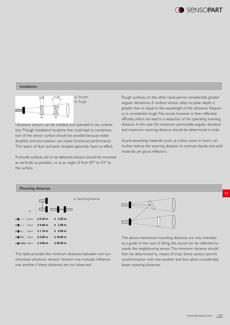
Ultrasonic sensors can be installed and operated in any orientation. Though installation locations that could lead to contamination of the sensor surface should be avoided because water droplets and encrustation can impair functional performance. Thin layers of dust and paint droplets generally have no effect.
If smooth surfaces are to be detected, sensors should be mounted as vertically as possible, i. e. at an angle of from 87° to 93° to the surface.
The table provides the minimum distances between nonsynchronised ultrasonic sensors. Sensors may mutually influence one another if these distances are not observed.
Rough surfaces, on the other hand, permit considerably greater angular deviations. A surface whose valleytopeak depth is greater than or equal to the wavelength of the ultrasonic frequen cy is considered rough. The sound, however, is then reflected diffusely, which can lead to a reduction of the operating scanning distance. In this case the maximum permissible angular deviation and maximum scanning distance should be determined in trials.
Soundabsorbing materials (such as cotton wool or foam) can further reduce the scanning distance. In contrast, liquids and solid materials are good reflectors.
The abovementioned mounting distances are only intended as a guide. In the case of tilting, the sound can be reflected towards the neighbouring sensor. The minimum distance should then be determined by means of trials. Some sensors permit synchronisation with one another and thus allow considerably lower scanning distances.
a) Switching distance
a) Smooth
b) Rough
a) b)
>> ±3°≤ ±3°
a)
≥ 0.35 m0.25 m
0.35 m
1.30 m
3.40 m
6.00 m
≥ 0.40 m
≥ 1.10 m
≥ 2.00 m
≥ 4.00 m ≥ 30.00 m
≥ 18.00 m
≥ 8.00 m
≥ 2.50 m
≥ 2.50 m
560 www.sensopart.com Version: 07/2016. Subject to changes; diagrams similar
Sensor data Functions
Limiting scanning distance
Operating scanning distance
Ultrasonic frequency
Resolution
Repeatability
Hysteresis
Temperature drift
250 mm
20 … 140 mm
~ 380 kHz
0.20 mm
± 0.15 %1
2 mm
0.17 % / °C
LED indicator, green
LED indicator, yellow
Scanning distance adjustment
Teachin modes
Adjustment possibilities
Default settings
Operating voltage indicator
Switching output indicator
Via Teachin button
Mode 1: set switching point Mode 2: set Window Mode Mode 3: set twoway / reflex switch
N.O. / N.C. via Teachin button Button lock via Teachin button Synchronisation via control input Default settings via Teachin button
Max. sensitivity and N.O.
Electrical data Mechanical data
Operating voltage, +UB
Noload current, I0Output current, Ie
Protective circuits
Protection Class
Power On Delay
Switching output, Q
Output function
Switching frequency, f (ti/tp 1:1)
Response time
Connection, WH
20 … 30 V DC2
≤ 25 mA
200 mA
Reversepolarity protection, UB / shortcircuit protection (Q)
2
< 300 ms
PNP / NPN (see Selection Table)
N.O. / N.C.
25 Hz
24 ms
Sync.
Dimensions
Enclosure rating
Material, housing
Material, ultrasonic converter
Type of connection
Ambient temperature, operation
Ambient temperature, storage
Weight
Vibration and impact resistance
32 x 38.5 x 12 mm
IP 673
ABS
Polyurethane foam, epoxy resin with glass content
(See Selection Table)
25 … +70 °C
40 … +85 °C
10 g
EN 6094752
1 From final value of limit scanning distance 2 Max. 10 % ripple, within UB 3 With connected IP 67 plug
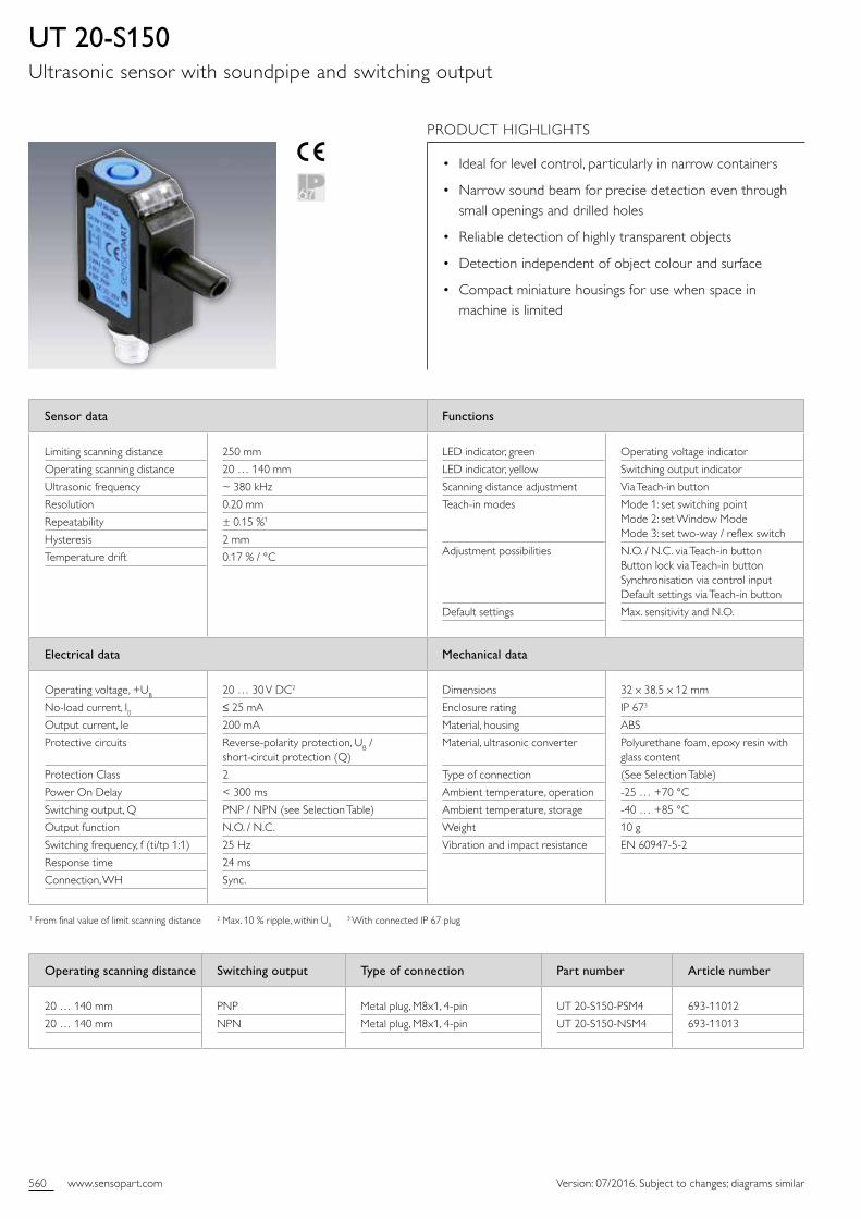
UT 20-S150Ultrasonic sensor with soundpipe and switching output
PRODUCT HIGHLIGHTS
• Ideal for level control, particularly in narrow containers
• Narrow sound beam for precise detection even through small openings and drilled holes
• Reliable detection of highly transparent objects
• Detection independent of object colour and surface
• Compact miniature housings for use when space in machine is limited
Operating scanning distance Switching output Type of connection Part number Article number
20 … 140 mm
20 … 140 mm
PNP
NPN
Metal plug, M8x1, 4pin
Metal plug, M8x1, 4pin
UT 20S150PSM4
UT 20S150NSM4
69311012
69311013
561www.sensopart.com
11
0 m
m
20 m
m
40 m
m
20 m
m
40 m
m
260 mm
20 mm
40 mm
60 mm
80 mm
100 mm
120 mm
140 mm
160 mm
180 mm
200 mm
220 mm
240 mm
sensor inactive sensor inactive
start measurement
t > 150 µs 8 ms < tp < 1 s
+UB
-UB
PNP
NPN
1 BN
2 WH
4 BK
3 BU
+UB
-UB3
OUT
SYNC
Version: 07/2016. Subject to changes; diagrams similar
Accessories
Connection cables
Brackets
From Page A38
From Page A4
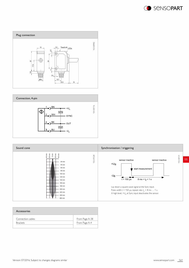
Plug connection
153
0098
2
Sound cone Synchronisation / triggering
155
0152
8
155
0013
1
Connection, 4-pin
154
0011
6
Lay down a squarewave signal at the Sync input. Pulse width t > 150 µs, repeat rate, tp = 8 ms … 1 s. A high level, +UB at Sync input deactivates the sensor.
562 www.sensopart.com Version: 07/2016. Subject to changes; diagrams similar
Sensor data1 Functions
Limiting scanning distance
Operating scanning distance
Ultrasonic frequency
Resolution
Repeatability
Temperature drift
250 mm
20 … 140 mm
~ 380 kHz
0.20 mm
± 0.15 %2
≤ 2 %
LED indicator, green
LED indicator, yellow
Set analogue characteristic
Adjustment possibilities
Operating voltage indicator
Switching output indicator
Via Teachin button
Rising / falling edge via Teachin button Button lock via Teachin button Synchronisation via control input Default settings via Teachin button
Electrical data Mechanical data
Operating voltage, +UB
Noload current, I0Current output
Voltage output
Protective circuits
Protection Class
Power On Delay
Analogue output
Response time
Connection, WH
20 … 30 V DC3
≤ 25 mA
Ra < 500 Ω
Ra > 500 Ω
Reversepolarity protection, UB / shortcircuit protection (Q)
2
< 300 ms
0 … 10 V / 4 … 20 mA (see Selection Table)
30 ms
Sync.
Dimensions
Enclosure rating
Material, housing
Material, ultrasonic converter
Type of connection
Ambient temperature, operation
Ambient temperature, storage
Weight
Vibration and impact resistance
32 x 38.5 x 12 mm
IP 674
ABS
Polyurethane foam, epoxy resin with glass content
(See Selection Table)
25 … +70 °C
40 … +85 °C
10 g
EN 6094752
1 After 30 min. settling time 2 From final value of limit scanning distance 3 Max. 10 % ripple, within UB 4 With connected IP 67 plug
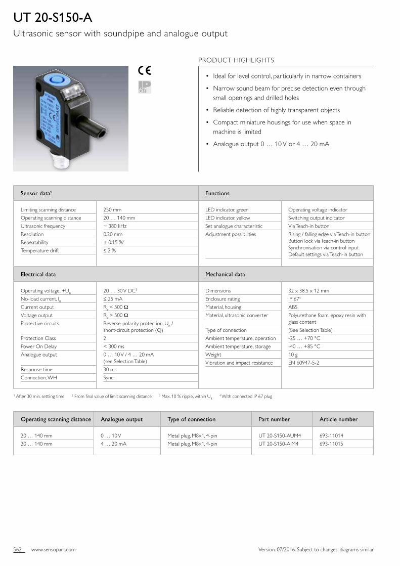
UT 20-S150-AUltrasonic sensor with soundpipe and analogue output
PRODUCT HIGHLIGHTS
• Ideal for level control, particularly in narrow containers
• Narrow sound beam for precise detection even through small openings and drilled holes
• Reliable detection of highly transparent objects
• Compact miniature housings for use when space in machine is limited
• Analogue output 0 … 10 V or 4 … 20 mA
Operating scanning distance Analogue output Type of connection Part number Article number
20 … 140 mm
20 … 140 mm
0 … 10 V
4 … 20 mA
Metal plug, M8x1, 4pin
Metal plug, M8x1, 4pin
UT 20S150AUM4
UT 20S150AIM4
69311014
69311015
563www.sensopart.com
11
0 m
m
20 m
m
40 m
m
20 m
m
40 m
m
260 mm
20 mm
40 mm
60 mm
80 mm
100 mm
120 mm
140 mm
160 mm
180 mm
200 mm
220 mm
240 mm
1 BN
2 WH
4 BK
3 BU
+UB
-UB
OUT
SYNC
Ra
sensor inactive sensor inactive
start measurement
t > 150 µs 8 ms < tp < 1 s
+UB
-UB
Version: 07/2016. Subject to changes; diagrams similar
Accessories
Connection cables
Brackets
From Page A38
From Page A4
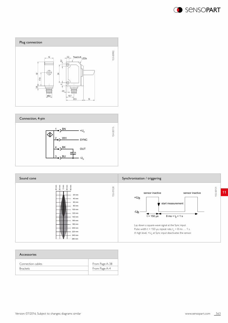
Plug connection
153
0098
2
Sound cone Synchronisation / triggering
155
0152
8
155
0013
1
Connection, 4-pin
154
0011
5
Lay down a squarewave signal at the Sync input. Pulse width t > 150 µs, repeat rate, tp = 8 ms … 1 s. A high level, +UB at Sync input deactivates the sensor.
564 www.sensopart.com Version: 07/2016. Subject to changes; diagrams similar
Sensor data Functions
Limit scanning distance
Operating scanning distance
Ultrasonic frequency
Resolution
Repeatability
Hysteresis
Temperature drift
250 mm
20 … 150 mm
~ 380 kHz
0.20 mm
± 0.15 %1
2 mm
0.17 % / °C
Indicator LED, green
Indicator LED, yellow
Scanning distance adjustment
Teachin modes
Adjustment possibilities
Default settings
Operating voltage indicator
Switching output indicator
Via Teachin button
Mode 1: set switching point Mode 2: set window operation Mode 3: set twoway / retroflective sensor
N.O. / N.C. via Teachin button Button lock via Teachin button Synchronisation via control input Default settings via Teachin button
Max. sensitivity and N.O.
Electrical data Mechanical data
Operating voltage, +UB
Noload current, I0Output current, Ie
Protective circuits
Protection Class
Power On Delay
Switching output, Q
Output function
Switching frequency, f (ti/tp 1:1)
Response time
Connection, WH
20 … 30 V DC2
≤ 25 mA
200 mA
Reverse polarity protection, UB / shortcircuit protection (Q)
2
< 300 ms
PNP / NPN (see Selection Table)
N.O. / N.C.
25 Hz
24 ms
Sync.
Dimensions
Enclosure rating
Material, housing
Material, ultrasonic converter
Type of connection
Ambient temperature: operation
Ambient temperature: storage
Weight
Vibration and impact resistance
32 x 21.6 x 12 mm
IP 673
ABS
Polyurethane foam, epoxy resin with glass content
(See Selection Table)
25 … +70 °C
40 … +85 °C
10 g
EN 6094752
1 From endvalue of limit scanning distance 2 Max. 10 % ripple, within UB 3 With connected IP 67 plug
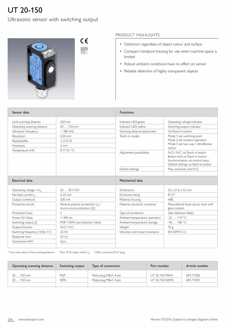
UT 20-150Ultrasonic sensor with switching output
PRODUCT HIGHLIGHTS
• Detection regardless of object colour and surface
• Compact miniature housing for use when machine space is limited
• Robust ambient conditions have no effect on sensor
• Reliable detection of highly transparent objects
Operating scanning distance Switching output Type of connection Part number Article number
20 … 150 mm
20 … 150 mm
PNP
NPN
Metal plug, M8x1, 4pin
Metal plug, M8x1, 4pin
UT 20150PSM4
UT 20150NSM4
69311000
69311001
565www.sensopart.com
1120 mm
40 mm
60 mm
80 mm
100 mm
120 mm
140 mm
160 mm
180 mm
200 mm
220 mm
240 mm
0 m
m
20 m
m
40 m
m
20 m
m
40 m
m
PNP
NPN
1 BN
2 WH
4 BK
3 BU
+UB
-UB3
OUT
SYNC
sensor inactive sensor inactive
start measurement
t > 150 µs 8 ms < tp < 1 s
+UB
-UB
Version: 07/2016. Subject to changes; diagrams similar
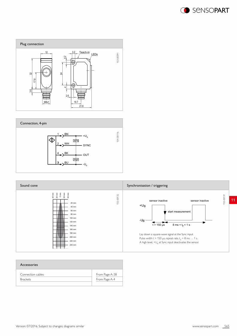
Plug connection
153
0039
1
Sound cone Synchronisation / triggering
155
0013
2
155
0013
1
Connection, 4-pin
154
0011
6
Accessories
Connection cables
Brackets
From Page A38
From Page A4
Lay down a squarewave signal at the Sync input. Pulse width t > 150 µs, repeat rate, tp = 8 ms … 1 s. A high level, +UB at Sync input deactivates the sensor.

566 www.sensopart.com Version: 07/2016. Subject to changes; diagrams similar
Sensor data1 Functions
Limit scanning distance
Operating scanning distance
Ultrasonic frequency
Resolution
Repeatability
Temperature drift
250 mm
20 … 150 mm
~ 380 kHz
0.20 mm
± 0.15 %2
≤ 2 %
Indicator LED, green
Indicator LED, yellow
Set characteristic analogue curve
Adjustment possibilities
Operating voltage indicator
Switching output indicator
Via Teachin button
Rising / falling slope via Teachin button Button lock via Teachin button Synchronisation via control input Default settings via Teachin button
Electrical data Mechanical data
Operating voltage, +UB
Noload current, I0Current output
Voltage output
Protective circuits
Protection Class
Power On Delay
Analogue output
Response time
Connection, WH
20 … 30 V DC3
≤ 25 mA
Ra < 500 Ω
Ra > 500 Ω
Reverse polarity protection, UB / shortcircuit protection (Q)
2
< 300 ms
0 … 10 V / 4 … 20 mA (see Selection Table)
30 ms
Sync.
Dimensions
Enclosure rating
Material, housing
Material, ultrasonic converter
Type of connection
Ambient temperature: operation
Ambient temperature: storage
Weight
Vibration and impact resistance
32 x 21.6 x 12 mm
IP 674
ABS
Polyurethane foam, epoxy resin with glass content
(See Selection Table)
25 … +70 °C
40 … +85 °C
10 g
EN 6094752
1 After 30 minutes settling time 2 From endvalue of limit scanning distance 3 Max. 10 % ripple, within UB 4 With connected IP 67 plug
UT 20-150-AUltrasonic sensor with analogue output
PRODUCT HIGHLIGHTS
• Detection regardless of object colour and surface
• Compact miniature housing for use when machine space is limited
• Synchronisation input – simultaneous operation of several sensors in highly limited spaces
• Analogue output: 0 … 10 V or 4 … 20 mA
Operating scanning distance Analogue output Type of connection Part number Article number
20 … 150 mm
20 … 150 mm
0 … 10 V
4 … 20 mA
Metal plug, M8x1, 4pin
Metal plug, M8x1, 4pin
UT 20150AUM4
UT 20150AIM4
69311004
69311005

567www.sensopart.com
11
1 BN
2 WH
4 BK
3 BU
+UB
-UB
OUT
SYNC
Ra
sensor inactive sensor inactive
start measurement
t > 150 µs 8 ms < tp < 1 s
+UB
-UB
20 mm
40 mm
60 mm
80 mm
100 mm
120 mm
140 mm
160 mm
180 mm
200 mm
220 mm
240 mm
0 m
m
20 m
m
40 m
m
20 m
m
40 m
m
Version: 07/2016. Subject to changes; diagrams similar
Plug connection
153
0039
1
Sound cone Synchronisation / triggering
155
0013
2
155
0013
1
Connection, 4-pin
154
0011
5
Accessories
Connection cables
Brackets
From Page A38
From Page A4
Lay down a squarewave signal at the Sync input. Pulse width t > 150 µs, repeat rate, tp = 8 ms … 1 s. A high level, +UB at Sync input deactivates the sensor.

568 www.sensopart.com Version: 07/2016. Subject to changes; diagrams similar
Sensor data Functions
Limit scanning distance
Operating scanning distance
Ultrasonic frequency
Resolution
Repeatability
Hysteresis
Temperature drift
350 mm
50 … 240 mm
~500 kHz
0.20 mm
± 0.15 %1
2 mm
0.17 % / °C
Indicator LED, green
Indicator LED, yellow
Scanning distance adjustment
Teachin modes
Adjustment possibilities
Default settings
Operating voltage indicator
Switching output indicator
Via Teachin button
Mode 1: set switching point Mode 2: set window operation Mode 3: set twoway / retroflective sensor
N.O. / N.C. via Teachin button Button lock via Teachin button Synchronisation via control input Default settings via Teachin button
Max. sensitivity and N.O.
Electrical data Mechanical data
Operating voltage, +UB
Noload current, I0Output current, Ie
Protective circuits
Protection Class
Power On Delay
Switching output, Q
Output function
Switching frequency, f (ti/tp 1:1)
Response time
Connection, WH
20 … 30 V DC2
≤ 25 mA
200 mA
Reverse polarity protection, UB / shortcircuit protection (Q)
2
< 300 ms
PNP / NPN (see Selection Table)
N.O. / N.C.
25 Hz
24 ms
Sync.
Dimensions
Enclosure rating
Material, housing
Material, ultrasonic converter
Type of connection
Ambient temperature: operation
Ambient temperature: storage
Weight
Vibration and impact resistance
32 x 23.1 x 12 mm
IP 673
ABS
Polyurethane foam, epoxy resin with glass content
(See Selection Table)
25 … +70 °C
40 … +85 °C
10 g
EN 6094752
1 From endvalue of limit scanning distance 2 Max. 10 % ripple, within UB 3 With connected IP 67 plug
UT 20-240Ultrasonic sensor with switching output
PRODUCT HIGHLIGHTS
• Ideal for monitoring filling levels, e.g. of liquids
• Reliable detection of highly transparent objects
• Detection regardless of object colour and surface
• Compact miniature housings for use when machine space is limited
Operating scanning distance Switching output Type of connection Part number Article number
50 … 240 mm
50 … 240 mm
PNP
NPN
Metal plug, M8x1, 4pin
Metal plug, M8x1, 4pin
UT 20240PSM4
UT 20240NSM4
69311002
69311003
569www.sensopart.com
110 mm
25 mm
50 mm
75 mm
100 mm
125 mm
150 mm
175 mm
200 mm
225 mm
250 mm
mm 0
mm 52
mm 05
mm 57
mm 001
mm 52
mm 05
mm 57
mm 001
mm 521
mm 521
275 mm
300 mm
325 mm
375 mm
400 mm
PNP
NPN
1 BN
2 WH
4 BK
3 BU
+UB
-UB3
OUT
SYNC
sensor inactive sensor inactive
start measurement
t > 150 µs 8 ms < tp < 1 s
+UB
-UB
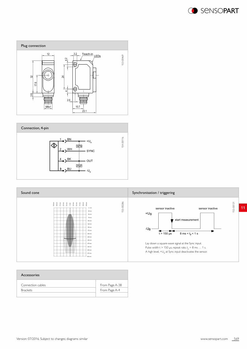
Version: 07/2016. Subject to changes; diagrams similar
Plug connection
153
0046
9
Sound cone Synchronisation / triggering
155
0028
6
155
0013
1
Connection, 4-pin
154
0011
6
Accessories
Connection cables
Brackets
From Page A38
From Page A4
Lay down a squarewave signal at the Sync input. Pulse width t > 150 µs, repeat rate, tp = 8 ms … 1 s. A high level, +UB at Sync input deactivates the sensor.

570 www.sensopart.com Version: 07/2016. Subject to changes; diagrams similar
Sensor data1 Functions
Limit scanning distance
Operating scanning distance
Ultrasonic frequency
Resolution
Repeatability
Temperature drift
350 mm
50 … 240 mm
~ 500 kHz
0.20 mm
± 0.15 %2
≤ 2 %
Indicator LED, green
Indicator LED, yellow
Set characteristic analogue curve
Adjustment possibilities
Operating voltage indicator
Switching output indicator
Via Teachin button
Rising / falling slope via Teachin button Button lock via Teachin button Synchronisation via control input Default settings via Teachin button
Electrical data Mechanical data
Operating voltage, +UB
Noload current, I0Current output
Voltage output
Protective circuits
Protection Class
Power On Delay
Analogue output
Response time
Connection, WH
20 … 30 V DC3
≤ 25 mA
Ra < 500 Ω
Ra > 500 Ω
Reverse polarity protection, UB / shortcircuit protection (Q)
2
< 300 ms
0 … 10 V / 4 … 20 mA (see Selection Table)
30 ms
Sync.
Dimensions
Enclosure rating
Material, housing
Material, ultrasonic converter
Type of connection
Ambient temperature: operation
Ambient temperature: storage
Weight
Vibration and impact resistance
32 x 23.1 x 12 mm
IP 674
ABS
Polyurethane foam, epoxy resin with glass content
(See Selection Table)
25 … +70 °C
40 … +85 °C
10 g
EN 6094752
1 After 30 minutes settling time 2 From endvalue of limit scanning distance 3 Max. 10 % ripple, within UB 4 With connected IP 67 plug
UT 20-240-AUltrasonic sensor with analogue output
PRODUCT HIGHLIGHTS
• Detection regardless of object colour and surface
• Compact miniature housing for use when machine space is limited
• Analogue output: 0 … 10 V or 4 … 20 mA
• Synchronisation input – simultaneous operation of several sensors in highly limited spaces
Operating scanning distance Analogue output Type of connection Part number Article number
50 … 240 mm
50 … 240 mm
0 … 10 V
4 … 20 mA
Metal plug, M8x1, 4pin
Metal plug, M8x1, 4pin
UT 20240AUM4
UT 20240AIM4
69311006
69311007

571www.sensopart.com
110 mm
25 mm
50 mm
75 mm
100 mm
125 mm
150 mm
175 mm
200 mm
225 mm
250 mm
mm 0
mm 52
mm 05
mm 57
mm 001
mm 52
mm 05
mm 57
mm 001
mm 521
mm 521
275 mm
300 mm
325 mm
375 mm
400 mm
1 BN
2 WH
4 BK
3 BU
+UB
-UB
OUT
SYNC
Ra
sensor inactive sensor inactive
start measurement
t > 150 µs 8 ms < tp < 1 s
+UB
-UB
Version: 07/2016. Subject to changes; diagrams similar
Plug connection
153
0046
9
Sound cone Synchronisation / triggering
155
0028
6
155
0013
1
Connection, 4-pin
154
0011
5
Accessories
Connection cables
Brackets
From Page A38
From Page A4
Lay down a squarewave signal at the Sync input. Pulse width t > 150 µs, repeat rate, tp = 8 ms … 1 s. A high level, +UB at Sync input deactivates the sensor.
572 www.sensopart.com Version: 07/2016. Subject to changes; diagrams similar
Sensor data Functions
Limit scanning distance
Operating scanning distance
Ultrasonic frequency
Resolution
Repeatability
Hysteresis
Temperature drift
1000 mm
120 … 700 mm
~ 300 kHz
0.20 mm
± 0.15 %1
2 mm
0.17 % / °C
Indicator LED, green
Indicator LED, yellow
Scanning distance adjustment
Teachin modes
Adjustment possibilities
Default settings
Operating voltage indicator
Switching output indicator
Via Teachin button
Mode 1: set switching point Mode 2: set window operation Mode 3: set twoway / retroflective sensor
N.O. / N.C. via Teachin button Button lock via Teachin button Synchronisation via control input Default settings via Teachin button
Max. sensitivity and N.O.
Electrical data Mechanical data
Operating voltage, +UB
Noload current, I0Output current, Ie
Protective circuits
Protection Class
Power On Delay
Switching output, Q
Output function
Switching frequency, f (ti/tp 1:1)
Response time
Connection, WH
20 … 30 V DC2
≤ 35 mA
200 mA
Reverse polarity protection, UB / shortcircuit protection (Q)
2
< 300 ms
PNP / NPN (see Selection Table)
N.O. / N.C.
14 Hz
42 ms
Sync.
Dimensions
Enclosure rating
Material, housing
Material, ultrasonic converter
Type of connection
Ambient temperature: operation
Ambient temperature: storage
Weight
Vibration and impact resistance
32 x 20 x 18 mm
IP 673
ABS
Polyurethane foam, epoxy resin with glass content
(See Selection Table)
25 … +70 °C
40 … +85 °C
10 g
EN 6094752
1 From endvalue of limit scanning distance 2 Max. 10 % ripple, within UB 3 With connected IP 67 plug
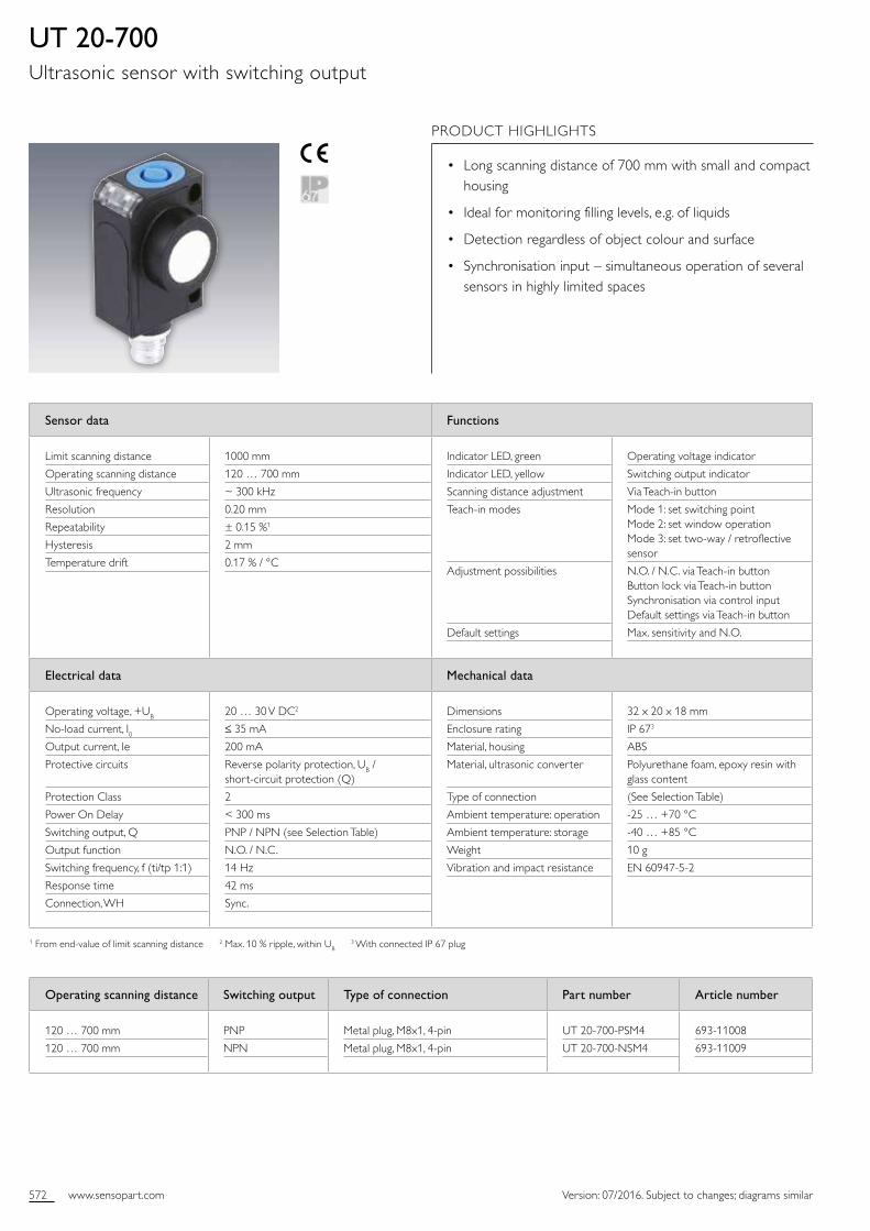
UT 20-700Ultrasonic sensor with switching output
PRODUCT HIGHLIGHTS
• Long scanning distance of 700 mm with small and compact housing
• Ideal for monitoring filling levels, e.g. of liquids
• Detection regardless of object colour and surface
• Synchronisation input – simultaneous operation of several sensors in highly limited spaces
Operating scanning distance Switching output Type of connection Part number Article number
120 … 700 mm
120 … 700 mm
PNP
NPN
Metal plug, M8x1, 4pin
Metal plug, M8x1, 4pin
UT 20700PSM4
UT 20700NSM4
69311008
69311009

573www.sensopart.com
110 mm
100 mm
300 mm
400 mm
500 mm
700 mm
600 mm
800 mm
900 mm
200 mm
1000 mm
1100 mm
1200 mm
400
mm
300
mm
100
mm
0 m
m
100
mm
300
mm
200
mm
400
mm
200
mm
PNP
NPN
1 BN
2 WH
4 BK
3 BU
+UB
-UB3
OUT
SYNC
sensor inactive sensor inactive
start measurement
t > 150 µs 8 ms < tp < 1 s
+UB
-UB
Version: 07/2016. Subject to changes; diagrams similar
Plug connection
153
0044
4
Sound cone Synchronisation / triggering
155
0044
0
155
0013
1
Connection, 4-pin
154
0011
6
Accessories
Connection cables
Brackets
From Page A38
From Page A4
Lay down a squarewave signal at the Sync input. Pulse width t > 150 µs, repeat rate, tp = 8 ms … 1 s. A high level, +UB at Sync input deactivates the sensor.
574 www.sensopart.com Version: 07/2016. Subject to changes; diagrams similar
Sensor data1 Functions
Limit scanning distance
Operating scanning distance
Ultrasonic frequency
Resolution
Repeatability
Temperature drift
1000 mm
120 … 700 mm
~ 300 kHz
0.20 mm
± 0.15 %2
≤ 2 %
Indicator LED, green
Indicator LED, yellow
Set characteristic analogue curve
Adjustment possibilities
Operating voltage indicator
Switching output indicator
Via Teachin button
Rising/falling edge via Teachin button Button lock via Teachin button Synchronisation via control input Default settings via Teachin button
Electrical data Mechanical data
Operating voltage, +UB
Noload current, I0Current output
Voltage output
Protective circuits
Protection Class
Power On Delay
Analogue output
Response time
Connection, WH
20 … 30 V DC2
≤ 35 mA
Ra < 500 Ω
Ra > 500 Ω
Reverse polarity protection, UB / shortcircuit protection (Q)
2
< 300 ms
0 … 10 V / 4 … 20 mA (see Selection Table)
30 ms
Sync.
Dimensions
Enclosure rating
Material, housing
Material, ultrasonic converter
Type of connection
Ambient temperature: operation
Ambient temperature: storage
Weight
Vibration and impact resistance
32 x 20 x 18 mm
IP 673
ABS
Polyurethane foam, epoxy resin with glass content
(See Selection Table)
25 … +70 °C
40 … +85 °C
10 g
EN 6094752
1 After 30 minutes settling time 2 Max. 10 % ripple, within UB 3 With connected IP 67 plug
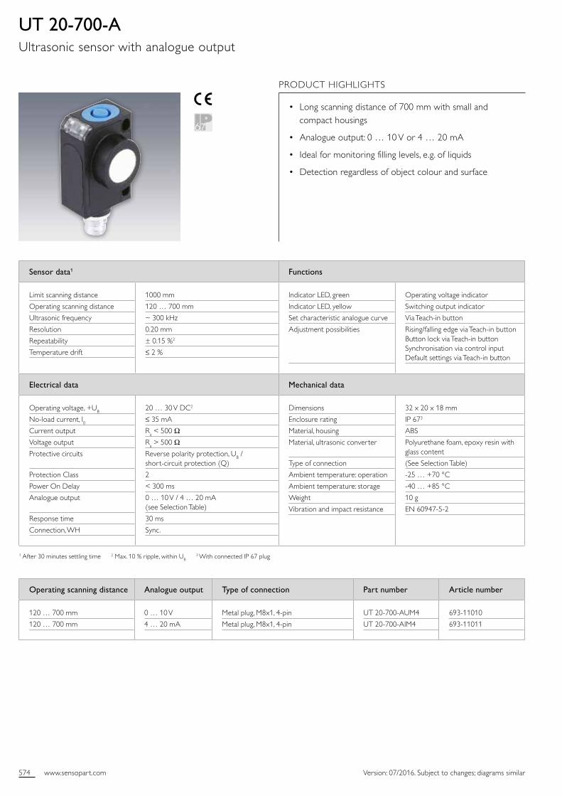
UT 20-700-AUltrasonic sensor with analogue output
PRODUCT HIGHLIGHTS
• Long scanning distance of 700 mm with small and compact housings
• Analogue output: 0 … 10 V or 4 … 20 mA
• Ideal for monitoring filling levels, e.g. of liquids
• Detection regardless of object colour and surface
Operating scanning distance Analogue output Type of connection Part number Article number
120 … 700 mm
120 … 700 mm
0 … 10 V
4 … 20 mA
Metal plug, M8x1, 4pin
Metal plug, M8x1, 4pin
UT 20700AUM4
UT 20700AIM4
69311010
69311011
575www.sensopart.com
110 mm
100 mm
300 mm
400 mm
500 mm
700 mm
600 mm
800 mm
900 mm
200 mm
1000 mm
1100 mm
1200 mm
400
mm
300
mm
100
mm
0 m
m
100
mm
300
mm
200
mm
400
mm
200
mm
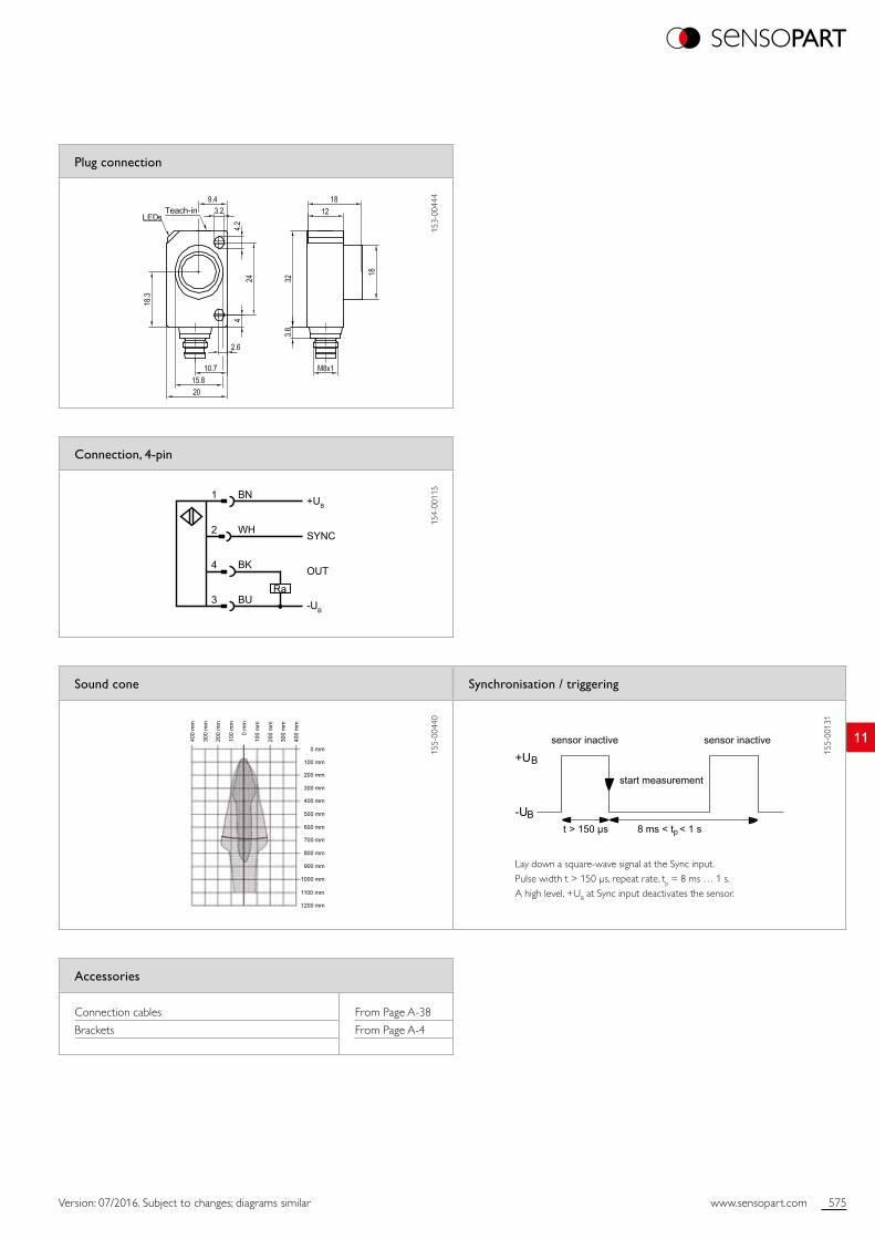
1 BN
2 WH
4 BK
3 BU
+UB
-UB
OUT
SYNC
Ra
sensor inactive sensor inactive
start measurement
t > 150 µs 8 ms < tp < 1 s
+UB
-UB
Version: 07/2016. Subject to changes; diagrams similar
Plug connection
153
0044
4
Sound cone Synchronisation / triggering
155
0044
0
155
0013
1
Connection, 4-pin
154
0011
5
Accessories
Connection cables
Brackets
From Page A38
From Page A4
Lay down a squarewave signal at the Sync input. Pulse width t > 150 µs, repeat rate, tp = 8 ms … 1 s. A high level, +UB at Sync input deactivates the sensor.
576 www.sensopart.com Version: 07/2016. Subject to changes; diagrams similar
Sensor data Functions
Operating scanning distance
Adjustment range
Ultrasonic frequency
Hysteresis
Temperature drift
Repeatability
30 … 400 mm
50 … 400 mm
~ 310 kHz
1 %1
± 1.5 %2
≤ 1 %
Indicator LED, yellow
Indicator LED, red
Scanning distance adjustment
Teachin modes
Default settings
Switching output indicator
Fault indicator
Via control input
Mode 1: set switching point (N.O. / N.C.) Mode 2: set window operation (N.O. / N.C.)
Switching point 1 = 50 mm, Switching point 2 = 400 mm
Electrical data Mechanical data
Operating voltage, +UB
Noload current, I0Output current, Ie
Voltage drop, UD
Protective circuits
Switching output, Q
Output function
Switching frequency, f (ti/tp 1:1)
Response time
Control input, WH
10 … 30 V DC3
≤ 30 mA
100 mA
≤ 3 V
Shortcircuit protection (Q) / overload protection
PNP
N.O. / N.C.
≤ 8 Hz
≤ 50 ms
UB = switching point 1 + UB = switching point 2
Dimensions
Enclosure rating
Material, housing
Material, ultrasonic converter
Type of connection
Ambient temperature: operation
Ambient temperature: storage
Weight
M12 x 70 mm
IP 654
Nickelplated brass
Polyurethane foam, epoxy resin with glass content, PBT (lid)
(See Selection Table)
25 … +70 °C
40 … +85 °C
25 g
1 Relating to set switching distance 2 From endvalue 3 Max. 10 % ripple, within UB 4 With connected IP 65 plug
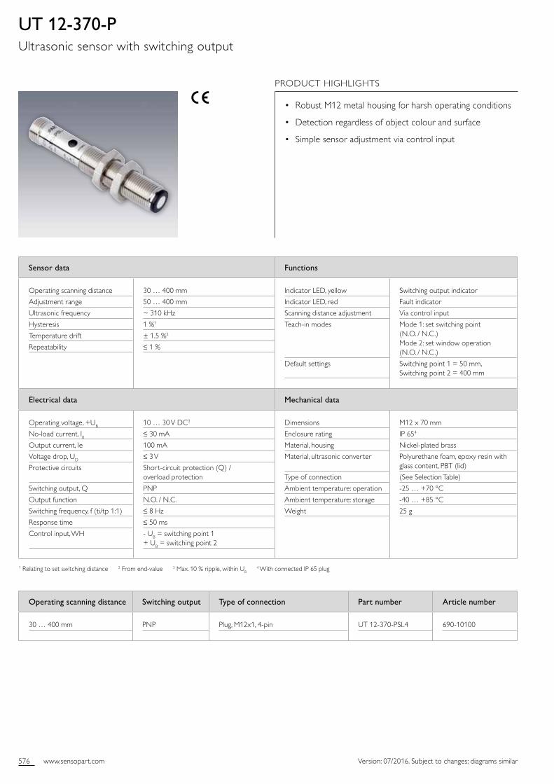
UT 12-370-PUltrasonic sensor with switching output
PRODUCT HIGHLIGHTS
• Robust M12 metal housing for harsh operating conditions
• Detection regardless of object colour and surface
• Simple sensor adjustment via control input
Operating scanning distance Switching output Type of connection Part number Article number
30 … 400 mm PNP Plug, M12x1, 4pin UT 12370PSL4 69010100
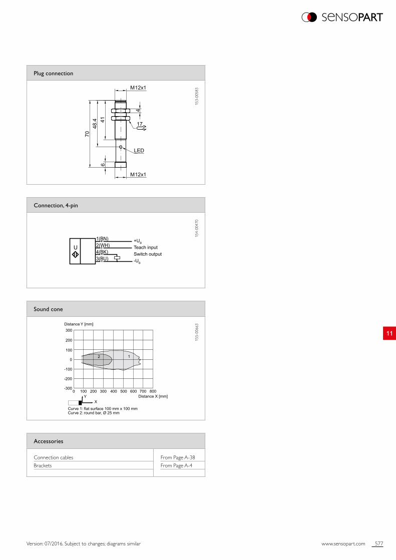
577www.sensopart.com
11
Distance X [mm]
Distance Y [mm]300
200
100
0
0 100 200 300 400 500 600 700 800
-100
-200
-300
12
Curve 1: flat surface 100 mm x 100 mmCurve 2: round bar, Ø 25 mm
XY
3(BU)
1(BN)2(WH)4(BK)
U+UB
Teach inputSwitch output-UB
Version: 07/2016. Subject to changes; diagrams similar
Plug connection
153
0058
3
Sound cone
155
0066
3
Connection, 4-pin
154
0047
0
Accessories
Connection cables
Brackets
From Page A38
From Page A4
578 www.sensopart.com Version: 07/2016. Subject to changes; diagrams similar
Sensor data Functions
Operating scanning distance
Adjustment range
Ultrasonic frequency
Resolution
Temperature drift
Repeatability
30 … 400 mm
50 … 400 mm
~ 310 kHz
0.40 mm1
± 1.5 %2
± 0.5 %2
Indicator LED, yellow
Indicator LED, red
Set characteristic analogue curve
Adjustment possibilities
Default settings
Switching output indicator
Fault indicator
Via control input
Rising / falling slope via control input
Evaluation limit 1 = 50 mm Evaluation limit 2 = 400 mm
Electrical data Mechanical data
Operating voltage, +UB
Noload current, I0Current output
Protective circuits
Analogue output
Response time
Control input, WH
10 … 30 V DC3
≤ 30 mA
Ra < 300 Ω
Shortcircuit protection (Q) / overload protection
4 … 20 mA
≤ 50 ms
UB = lower evaluation limit + UB = upper evaluation limit
Dimensions
Enclosure rating
Material, housing
Material, ultrasonic converter
Type of connection
Ambient temperature: operation
Ambient temperature: storage
Weight
M12 x 70 mm
IP 654
Nickelplated brass
Polyurethane foam, epoxy resin with glass content, PBT (lid)
(See Selection Table)
25 … +70 °C
40 … +85 °C
25 g
1 With max. detection range 2 From endvalue 3 Max. 10 % ripple, within UB 4 With connected IP 65 plug
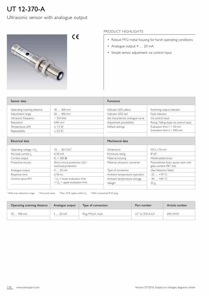
UT 12-370-AUltrasonic sensor with analogue output
PRODUCT HIGHLIGHTS
• Robust M12 metal housing for harsh operating conditions
• Analogue output: 4 … 20 mA
• Simple sensor adjustment via control input
Operating scanning distance Analogue output Type of connection Part number Article number
30 … 400 mm 4 … 20 mA Plug, M12x1, 4pin UT 12370AIL4 69010101

579www.sensopart.com
11
Distance X [mm]
Distance Y [mm]300
200
100
0
0 100 200 300 400 500 600 700 800
-100
-200
-300
12
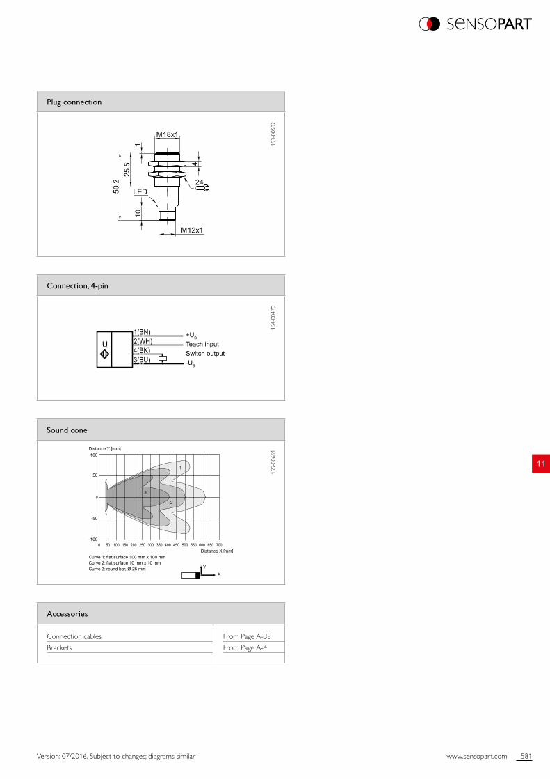
Curve 1: flat surface 100 mm x 100 mmCurve 2: round bar, Ø 25 mm
XY
3(BU)
1(BN)2(WH)4(BK)
U+UB
Teach inputAnalogue output-UB
Version: 07/2016. Subject to changes; diagrams similar
Plug connection
153
0058
3
Sound cone
155
0066
3
Connection, 4-pin
154
0046
9
Accessories
Connection cables
Brackets
From Page A38
From Page A4

580 www.sensopart.com Version: 07/2016. Subject to changes; diagrams similar
Sensor data Functions
Operating scanning distance
Adjustment range
Ultrasonic frequency
Hysteresis
Temperature drift
Repeatability
35 … 300 mm
50 … 300 mm
~ 390 kHz
1 %1
± 1.5 %2
≤ 1 %
Indicator LED, green
Indicator LED, yellow
Indicator LED, red
Scanning distance adjustment
Teachin modes
Default settings
Operating voltage indicator
Switching output indicator
Fault indicator
Via control input
Mode 1: set switching point (N.O. / N.C.) Mode 2: set window operation (N.O. / N.C.)
Switching point 1 = 50 mm Switching point 2 = 300 mm
Electrical data Mechanical data
Operating voltage, +UB
Noload current, I0Output current, Ie
Voltage drop, UD
Protective circuits
Switching output, Q
Output function
Switching frequency, f (ti/tp 1:1)
Response time
Control input, WH
10 … 30 V DC3
≤ 20 mA
200 mA
≤ 3 V
Shortcircuit protection (Q) / overload protection
PNP
N.O. / N.C.
≤ 13 Hz
≤ 30 ms
UB = switching point 1 + UB = switching point 2
Dimensions
Enclosure rating
Material, housing
Material, ultrasonic converter
Type of connection
Ambient temperature: operation
Ambient temperature: storage
Weight
M18 x 50.2 mm
IP 654
Nickelplated brass
Polyurethane foam, epoxy resin with glass content, PBT (lid)
(See Selection Table)
25 … +70 °C
40 … +85 °C
25 g
1 Relating to set switching distance 2 From endvalue 3 Max. 10 % ripple, within UB 4 With connected IP 65 plug
UT 18-270-PUltrasonic sensor with switching output
PRODUCT HIGHLIGHTS
• Robust M18 metal housing for harsh operating conditions
• Detection regardless of object colour and surface
• Adjustable window mode
• Selectable N.O. / N.C.
Operating scanning distance Switching output Type of connection Part number Article number
30 … 300 mm PNP Plug, M12x1, 4pin UT 18270PSL4 69010102
581www.sensopart.com
11
Distance X [mm]
Distance Y [mm]
Curve 1: flat surface 100 mm x 100 mmCurve 2: flat surface 10 mm x 10 mmCurve 3: round bar, Ø 25 mm
XY
1
2
3
100
50
50 100 150 200 250 300 350 400 450 550500 650600 7000
0
-50
-100
3(BU)
1(BN)2(WH)4(BK)
U+UB
Teach inputSwitch output-UB
Version: 07/2016. Subject to changes; diagrams similar
Plug connection
153
0058
2
Sound cone
155
0066
1
Connection, 4-pin
154
0047
0
Accessories
Connection cables
Brackets
From Page A38
From Page A4
582 www.sensopart.com Version: 07/2016. Subject to changes; diagrams similar
Sensor data Functions
Operating scanning distance
Adjustment range
Ultrasonic frequency
Resolution
Temperature drift
Repeatability
35 … 300 mm
50 … 300 mm
~ 390 kHz
0.40 mm1
± 1.5 %2
± 0.5 %2
Indicator LED, green
Indicator LED, yellow
Indicator LED, red
Set characteristic analogue curve
Adjustment possibilities
Default settings
Operating voltage indicator
Switching output indicator
Fault indicator
Via control input
Rising / falling slope via control input
Evaluation limit 1 = 50 mm Evaluation limit 2 = 300 mm
Electrical data Mechanical data
Operating voltage, +UB
Noload current, I0Current output
Protective circuits
Analogue output
Response time
Control input, WH
10 … 30 V DC3
≤ 20 mA
Ra < 300 Ω
Shortcircuit protection (Q) / overload protection
4 … 20 mA
≤ 30 ms
UB = lower evaluation limit + UB = upper evaluation limit
Dimensions
Enclosure rating
Material, housing
Material, ultrasonic converter
Type of connection
Ambient temperature: operation
Ambient temperature: storage
Weight
M18 x 50.2 mm
IP 654
Nickelplated brass
Polyurethane foam, epoxy resin with glass content, PBT (lid)
(See Selection Table)
25 … +70 °C
40 … +85 °C
25 g
1 With max. detection range 2 From endvalue 3 Max. 10 % ripple, within UB 4 With connected IP 65 plug
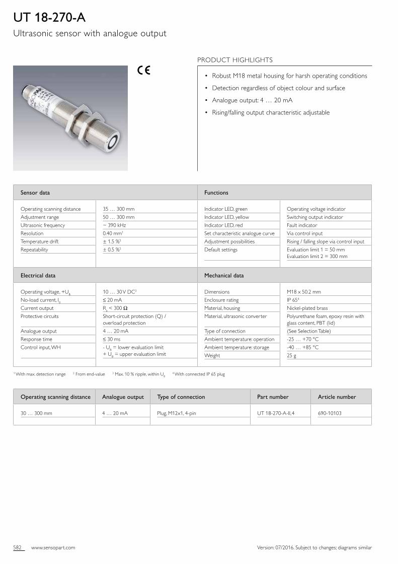
UT 18-270-AUltrasonic sensor with analogue output
PRODUCT HIGHLIGHTS
• Robust M18 metal housing for harsh operating conditions
• Detection regardless of object colour and surface
• Analogue output: 4 … 20 mA
• Rising/falling output characteristic adjustable
Operating scanning distance Analogue output Type of connection Part number Article number
30 … 300 mm 4 … 20 mA Plug, M12x1, 4pin UT 18270AIL4 69010103

583www.sensopart.com
11
Distance X [mm]
Distance Y [mm]
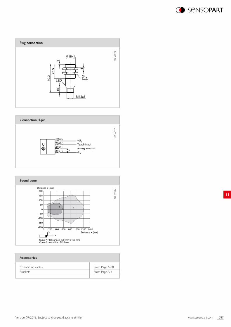
Curve 1: flat surface 100 mm x 100 mmCurve 2: flat surface 10 mm x 10 mmCurve 3: round bar, Ø 25 mm
XY
1
2
3
100
50
50 100 150 200 250 300 350 400 450 550500 650600 7000
0
-50
-100
3(BU)
1(BN)2(WH)4(BK)
U+UB
Teach inputAnalogue output-UB
Version: 07/2016. Subject to changes; diagrams similar
Plug connection
153
0058
2
Sound cone
155
0066
1
Connection, 4-pin
154
0046
9
Accessories
Connection cables
Brackets
From Page A38
From Page A4

584 www.sensopart.com Version: 07/2016. Subject to changes; diagrams similar
Sensor data Functions
Operating scanning distance
Adjustment range
Ultrasonic frequency
Hysteresis
Temperature drift
Repeatability
50 … 800 mm
70 … 800 mm
~ 205 kHz
1 %1
± 1.5 %2
≤ 1 %
Indicator LED, green
Indicator LED, yellow
Indicator LED, red
Scanning distance adjustment
Teachin modes
Default settings
Operating voltage indicator
Switching output indicator
Fault indicator
Via control input
Mode 1: set switching point (N.O. / N.C.) Mode 2: set window operation (N.O. / N.C.)
Switching point 1 = 70 mm Switching point 2 = 800 mm
Electrical data Mechanical data
Operating voltage, +UB
Noload current, I0Output current, Ie
Voltage drop, UD
Protective circuits
Switching output, Q
Output function
Switching frequency, f (ti/tp 1:1)
Response time
Control input, WH
10 … 30 V DC3
≤ 20 mA
200 mA
≤ 3 V
Shortcircuit protection (Q) / overload protection
PNP
N.O. / N.C.
≤ 4 Hz
≤ 100 ms
UB = switching point 1 + UB = switching point 2
Dimensions
Enclosure rating
Material, housing
Material, ultrasonic converter
Type of connection
Ambient temperature: operation
Ambient temperature: storage
Weight
M18 x 50.2 mm
IP 654
Nickelplated brass
Polyurethane foam, epoxy resin with glass content, PBT (lid)
(See Selection Table)
25 … +70 °C
40 … +85 °C
25 g
1 Relating to set switching distance 2 From endvalue 3 Max. 10 % ripple, within UB 4 With connected IP 65 plug
UT 18-750-PUltrasonic sensor with switching output
PRODUCT HIGHLIGHTS
• Long operating scanning distance of 800 mm
• Robust M18 metal housing for harsh operating conditions
• Simple sensor adjustment via control input
• Window mode adjustable
• N.O. / N.C. selectable
Operating scanning distance Switching output Type of connection Part number Article number
50 … 800 mm PNP Plug, M12x1, 4pin UT 18750PSL4 69010104

585www.sensopart.com
11
Distance X [mm]
Distance Y [mm]200
150
100
50
0
0 200 400 600 800 1000 1200 1400
-50
-100
-150
-200
12
X
Curve 1: flat surface 100 mm x 100 mmCurve 2: round bar, Ø 25 mm
Y
3(BU)
1(BN)2(WH)4(BK)
U+UB
Teach inputSwitch output-UB
Version: 07/2016. Subject to changes; diagrams similar
Plug connection
153
0058
2
Sound cone
155
0066
2
Connection, 4-pin
154
0047
0
Accessories
Connection cables
Brackets
From Page A38
From Page A4

586 www.sensopart.com Version: 07/2016. Subject to changes; diagrams similar
Sensor data Functions
Operating scanning distance
Adjustment range
Ultrasonic frequency
Resolution
Temperature drift
Repeatability
50 … 800 mm
70 … 800 mm
~ 205 kHz
0.40 mm1
± 1.5 %2
± 0.5 %2
Indicator LED, green
Indicator LED, yellow
Indicator LED, red
Set characteristic analogue curve
Adjustment possibilities
Default settings
Operating voltage indicator
Switching output indicator
Fault indicator
Via control input
Rising / falling slope via control input
Evaluation limit 1 = 70 mm Evaluation limit 2 = 800 mm
Electrical data Mechanical data
Operating voltage, +UB
Noload current, I0Current output
Protective circuits
Analogue output
Response time
Control input, WH
10 … 30 V DC3
≤ 20 mA
Ra < 300 Ω
Shortcircuit protection (Q) / overload protection
4 … 20 mA
≤ 100 ms
UB = lower evaluation limit + UB = upper evaluation limit
Dimensions
Enclosure rating
Material, housing
Material, ultrasonic converter
Type of connection
Ambient temperature: operation
Ambient temperature: storage
Weight
M18 x 50.2 mm
IP 654
Nickelplated brass
Polyurethane foam, epoxy resin with glass content, PBT (lid)
(See Selection Table)
25 … +70 °C
40 … +85 °C
25 g
1 With max. detection range 2 From endvalue 3 Max. 10 % ripple, within UB 4 With connected IP 65 plug
UT 18-750-AUltrasonic sensor with analogue output
PRODUCT HIGHLIGHTS
• Long operating scanning distance of 800 mm
• Robust M18 metal housing for harsh operating conditions
• Analogue output: 4 … 20 mA
• Rising / falling output characteristic adjustable
Operating scanning distance Analogue output Type of connection Part number Article number
50 … 800 mm 4 … 20 mA Plug, M12x1, 4pin UT 18750AIL4 69010105
587www.sensopart.com
11
Distance X [mm]
Distance Y [mm]200
150
100
50
0
0 200 400 600 800 1000 1200 1400
-50
-100
-150
-200
12
X
Curve 1: flat surface 100 mm x 100 mmCurve 2: round bar, Ø 25 mm
Y
3(BU)
1(BN)2(WH)4(BK)
U+UB
Teach inputAnalogue output-UB
Version: 07/2016. Subject to changes; diagrams similar
Plug connection
153
0058
2
Sound cone
155
0066
2
Connection, 4-pin
154
0046
9
Accessories
Connection cables
Brackets
From Page A38
From Page A4
588 www.sensopart.com Version: 07/2016. Subject to changes; diagrams similar
Sensor data Functions
Limit scanning distance
Operating scanning distance
Ultrasonic frequency
Resolution
Repeatability1
Hysteresis
Temperature drift
350 mm
30 … 250 mm
~ 320 kHz
0.36 mm
< 1 mm
2 mm
0.17 % / K
Adjustment possibilities Operating scanning distance 60 mm / 250 mm via control input
Electrical data Mechanical data
Operating voltage, +UB
Noload current, I0Output current, Ie
Voltage drop, Ud
Protective circuits
Switching output, Q
Output function
Switching frequency, f (ti/tp 1:1)
Control input, WH
10 … 30 V DC2
≤ 30 mA
500 mA
< 2.4 V DC
Reverse polarity protection, UB / shortcircuit protection (Q)
PNP
N.O.
25 Hz
+ UB = operating scanning distance 250 mm UB / open = operating scanning distance 60 mm
Dimensions
Enclosure rating
Material, housing
Type of connection
Ambient temperature: operation
Ambient temperature: storage
Weight
M18 x 95 mm
IP 653
(See Selection Table)
(See Selection Table)
20 … +70 °C
40 … +85 °C
80 g
1 With constant ambient conditions 2 Max. 10 % ripple, within UB 3 With connected IP 65 plug
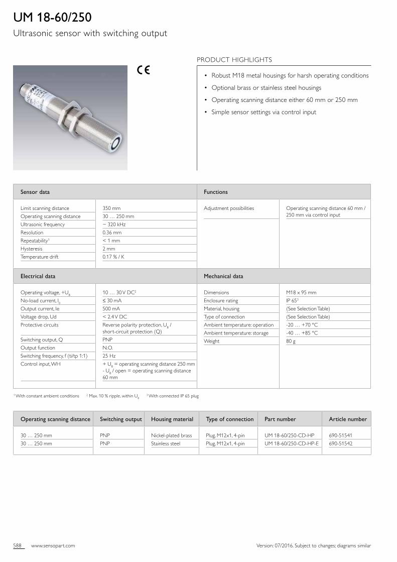
UM 18-60/250Ultrasonic sensor with switching output
PRODUCT HIGHLIGHTS
• Robust M18 metal housings for harsh operating conditions
• Optional brass or stainless steel housings
• Operating scanning distance either 60 mm or 250 mm
• Simple sensor settings via control input
Operating scanning distance Switching output Housing material Type of connection Part number Article number
30 … 250 mm
30 … 250 mm
PNP
PNP
Nickelplated brass
Stainless steel
Plug, M12x1, 4pin
Plug, M12x1, 4pin
UM 1860/250CDHP
UM 1860/250CDHPE
69051541
69051542
589www.sensopart.com
11
Tube Ø 10 mm
Aligned plate
50 m
m
0 m
m
100
mm
300 mm
350 mm
250 mm
200 mm
150 mm
100 mm
50 mm
0 mm
50 m
m
100
mm
+UB
-UB3
PNP
1 BN
2 WH
4 BK
3 BU
4:
CONTROL
Version: 07/2016. Subject to changes; diagrams similar
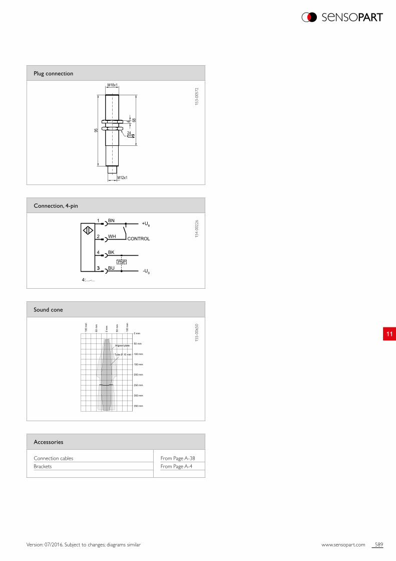
Plug connection
153
0057
2
Sound cone
155
0065
0
Connection, 4-pin
154
0022
6
Accessories
Connection cables
Brackets
From Page A38
From Page A4
590 www.sensopart.com Version: 07/2016. Subject to changes; diagrams similar
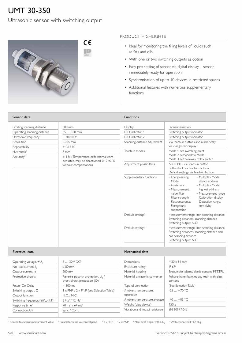
UMT 30-350Ultrasonic sensor with switching output
Sensor data Functions
Limiting scanning distance
Operating scanning distance
Ultrasonic frequency
Resolution
Repeatability
Hysteresis2
Accuracy2
600 mm
65 … 350 mm
~ 400 kHz
0.025 mm
± 0.15 %1
5 mm
± 1 % ( Temperature drift internal compensated, may be deactivated, 0.17 % / K without compensation)
Display
LED indicator 1
LED indicator 2
Scanning distance adjustment
Teachin modes
Adjustment possibilities
Supplementary functions
Default settings3
Default settings4
Parameterisation
Switching output indicator
Switching output indicator
Via Teachin buttons and numerically via 7segment display
Mode 1: set switching point Mode 2: set Window Mode Mode 3: set twoway reflex switch
N.O. / N.C. via Teachin button Button lock via Teachin button Default settings via Teachin button
– Energysaving Mode – Hysteresis – Measurement value filter – Filter strength – Response delay – Foreground suppression
Measurement range: limit scanning distance Switching distances: scanning distance Switching output: N.O.
Measurement range: limit scanning distance Switching distances: scanning distance and half scanning distance Switching output: N.O.
Electrical data Mechanical data
Operating voltage, +UB
Noload current, I0Output current, Ie
Protective circuits
Power On Delay
Switching output, Q
Output function
Switching frequency, f (ti/tp 1:1)2
Response time2
Connection, GY
9 … 30 V DC5
≤ 80 mA
200 mA
Reversepolarity protection, UB / shortcircuit protection (Q)
< 300 ms
1 x PNP / 2 x PNP (see Selection Table)
N.O. / N.C.
8 Hz3 / 12 Hz4
70 ms3 / 64 ms4
Sync. / Com.
Dimensions
Enclosure rating
Material, housing
Material, ultrasonic converter
Type of connection
Ambient temperature, operation
Ambient temperature, storage
Weight (plug device)
Vibration and impact resistance
M30 x 84 mm
IP 676
Brass, nickelplated, plastic content: PBT, TPU
Polyurethane foam, epoxy resin with glass content
(See Selection Table)
25 … +70 °C
40 … +85 °C
150 g
EN 6094752
1 Related to current measurement value 2 Parameterisable via control panel 3 1 x PNP 4 2 x PNP 5 Max. 10 % ripple, within UB 6 With connected IP 67 plug
PRODUCT HIGHLIGHTS
• Ideal for monitoring the filling levels of liquids such as fats and oils
• With one or two switching outputs as option
• Easy presetting of sensor via digital display – sensor immediately ready for operation
• Synchronisation of up to 10 devices in restricted spaces
• Additional features with numerous supplementary functions
– Multiplex Mode, device address – Multiplex Mode, highest address – Measurement range – Calibration display – Detection range, sensitivity
591www.sensopart.com
11
0 mm
100 mm
200 mm
300 mm
400 mm
500 mm
600 mm
100
mm
0 m
m
100
mm
350 mm
Aligned Plate
Tube ø 27 mm
+UB
-UB
Q (PNP)Sync/Com
12453
1 PNP switched output
U+UB
-UB
Q1 (PNP)Q2 (PNP)Sync/Com
12453
2 PNP switched outputs
U
A B
Version: 07/2016. Subject to changes; diagrams similar
≤ 2.50 m
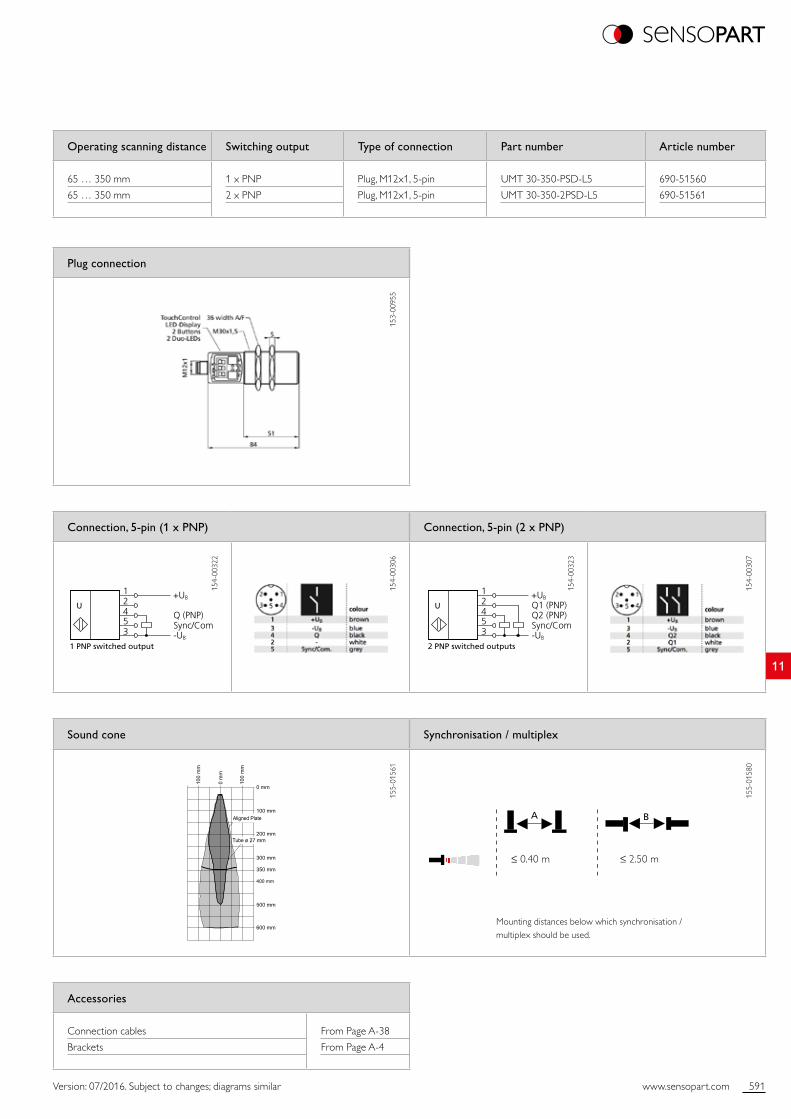
Plug connection
153
0095
5
Sound cone Synchronisation / multiplex
155
0156
1
155
0158
0
Operating scanning distance Switching output Type of connection Part number Article number
65 … 350 mm
65 … 350 mm
1 x PNP
2 x PNP
Plug, M12x1, 5pin
Plug, M12x1, 5pin
UMT 30350PSDL5
UMT 303502PSDL5
69051560
69051561
Connection, 5-pin (1 x PNP) Connection, 5-pin (2 x PNP)
154
0032
2
154
0030
6
154
0032
3
154
0030
7
Mounting distances below which synchronisation / multiplex should be used.
Accessories
Connection cables
Brackets
From Page A38
From Page A4
≤ 0.40 m
592 www.sensopart.com Version: 07/2016. Subject to changes; diagrams similar
Sensor data Functions
Limiting scanning distance
Operating scanning distance
Ultrasonic frequency
Resolution 1
Repeatability
Accuracy3
600 mm
65 … 350 mm
~ 400 kHz
0.025 ... 0.17 mm
± 0.15 %2
± 1 % ( Temperature drift internal compensated, may be deactivated, 0.17 % / K without compensation)
Display
LED indicator 1
LED indicator 2
Set analogue characteristic
Teachin modes
Adjustment possibilities
Supplementary functions
Default settings
Parameterisation
Switching output indicator
Switching output indicator
Via Teachin button and numerically via 7segment display
Mode 1: set window limits Mode 2: rising / falling output characteristics
Button lock via Teachin button Default settings via Teachin button
– Energysaving Mode – Indicator Mode – Current or voltage output selection – Measurement value filter – Filter strength – Response delay – Foreground suppression – Multiplex Mode, device address – Multiplex Mode, highest address – Measurement range – Calibration display – Detection range, sensitivity
Measurement range: limit scanning distance Window limits, analogue signal: blind zone and scanning distance Switching output: rising analogue characteristic
Electrical data Mechanical data
Operating voltage, +UB
Noload current, I0Current output
Voltage output
Protective circuits
Power On Delay
Analogue output
Response time3
Connection, GY
9 … 30 V DC4
≤ 80 mA
RL ≤ 100 Ω with 9 V ≤ UB ≤ 20 V RL ≤ 500 Ω with UB ≥ 20 V
RL ≥ 100 kΩ with UB ≥ 15 V
Reversepolarity protection, UB / shortcircuit protection (Q)
< 300 ms
0 … 10 V / 4 … 20 mA
64 ms
Sync. / Com.
Dimensions
Enclosure rating
Material, housing
Material, ultrasonic converter
Type of connection
Ambient temperature, operation
Ambient temperature, storage
Weight
Vibration and impact resistance
M30 x 84 mm
IP 675
Brass, nickelplated, plastic content: PBT, TPU
Polyurethane foam, epoxy resin with glass content
(See Selection Table)
25 … +70 °C
40 … +85 °C
150 g
EN 6094752
1 depending on the set analogue window 2 Related to current measurement value 3 Parameterisable via control panel 4 Max. 10 % ripple, within UB 5 With connected IP 67 plug
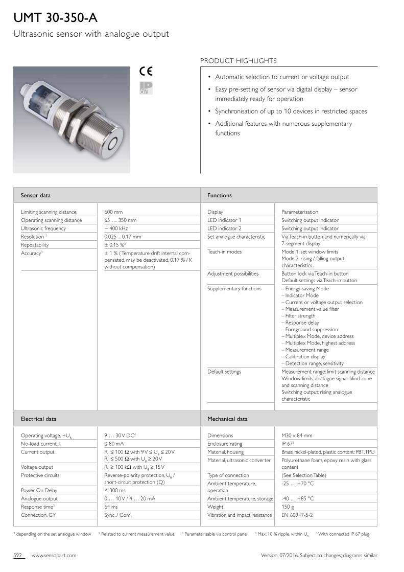
UMT 30-350-AUltrasonic sensor with analogue output
PRODUCT HIGHLIGHTS
• Automatic selection to current or voltage output
• Easy presetting of sensor via digital display – sensor immediately ready for operation
• Synchronisation of up to 10 devices in restricted spaces
• Additional features with numerous supplementary functions
593www.sensopart.com
11
0 mm
100 mm
200 mm
300 mm
400 mm
500 mm
600 mm
100
mm
0 m
m
100
mm
350 mm
Aligned Plate
Tube ø 27 mm
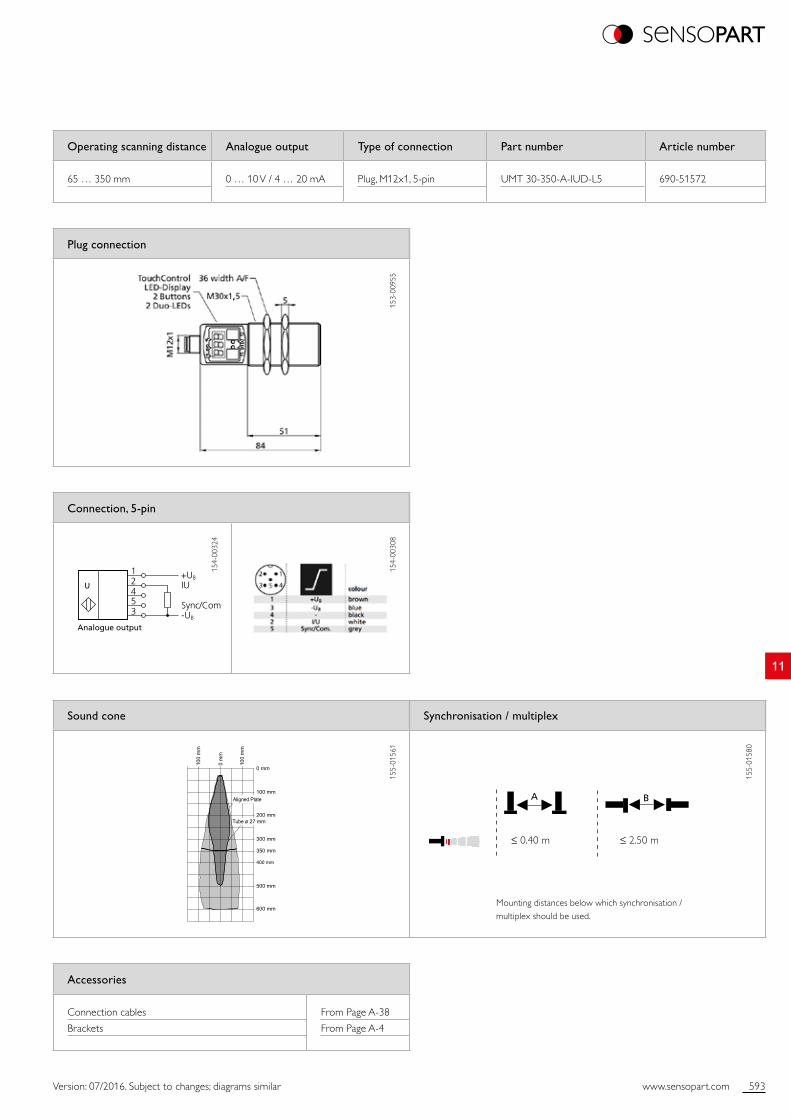
Analogue output
+UB
-UB
IU
Sync/Com
12453
U
A B
Version: 07/2016. Subject to changes; diagrams similar
Plug connection
153
0095
5
Operating scanning distance Analogue output Type of connection Part number Article number
65 … 350 mm 0 … 10 V / 4 … 20 mA Plug, M12x1, 5pin UMT 30350AIUDL5 69051572
Connection, 5-pin
154
0032
4
154
0030
8
≤ 0.40 m ≤ 2.50 m
Mounting distances below which synchronisation / multiplex should be used.
Sound cone Synchronisation / multiplex
155
0156
1
155
0158
0
Accessories
Connection cables
Brackets
From Page A38
From Page A4
594 www.sensopart.com Version: 07/2016. Subject to changes; diagrams similar
Sensor data Functions
Limiting scanning distance
Operating scanning distance
Ultrasonic frequency
Resolution
Repeatability
Hysteresis2
Accuracy2
2000 mm
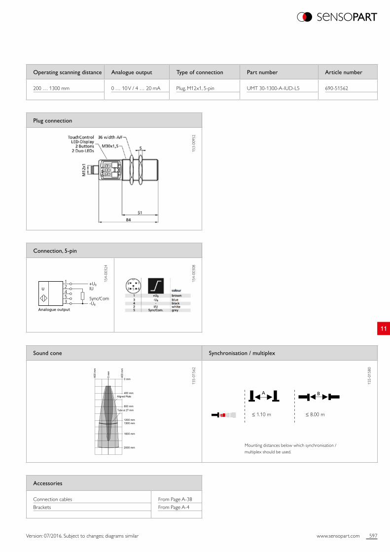
200 … 1300 mm
~ 200 kHz
0.18 mm
± 0.15 %1
20 mm
± 1 % ( Temperature drift internal compensated, may be deactivated, 0.17 % / K without compensation)
Display
LED indicator 1
LED indicator 2
Scanning distance adjustment
Teachin modes
Adjustment possibilities
Supplementary functions
Default settings3
Default settings4
Parameterisation
Switching output indicator
Switching output indicator
Via Teachin buttons and numerically via 7segment display
Mode 1: set switching point Mode 2: set Window Mode Mode 3: set twoway reflex switch
N.O. / N.C. via teachin button Button lock via teachin button Default settings via teachin button
– Energysaving Mode – Hysteresis – Measurement value filter – Filter strength – Response delay – Foreground suppression
Measurement range: limit scanning distance Switching distances: scanning distance Switching output: N.O.
Measurement range: limit scanning distance Switching distances: scanning distance and half scanning distance Switching output: N.O.
Electrical data Mechanical data
Operating voltage, +UB
Noload current, I0Output current, Ie
Protective circuits
Power On Delay
Switching output, Q
Output function
Switching frequency, f (ti/tp 1:1)2
Response time2
Connection, GY
9 … 30 V DC5
≤ 80 mA
200 mA
Reversepolarity protection, UB / shortcircuit protection (Q)
< 300 ms
1 x PNP / 2 x PNP (see Selection Table)
N.O. / N.C.
6 Hz3 / 8 Hz4
110 ms3 / 92 ms4
Sync. / Com.
Dimensions
Enclosure rating
Material, housing
Material, ultrasonic converter
Type of connection
Ambient temperature, operation
Ambient temperature, storage
Weight
Vibration and impact resistance
M30 x 84 mm
IP 676
Brass, nickelplated, plastic content: PBT, TPU
Polyurethane foam, epoxy resin with glass content
(See Selection Table)
25 … +70 °C
40 … +85 °C
150 g
EN 6094752
1 Related to current measurement value 2 Parameterisable via control panel 3 1 x PNP 4 2 x PNP 5 Max. 10 % ripple, within UB 6 With connected IP 67 plug
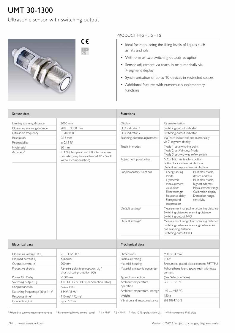
UMT 30-1300Ultrasonic sensor with switching output
PRODUCT HIGHLIGHTS
• Ideal for monitoring the filling levels of liquids such as fats and oils
• With one or two switching outputs as option
• Sensor adjustment via teachin or numerically via 7segment display
• Synchronisation of up to 10 devices in restricted spaces
• Additional features with numerous supplementary functions
– Multiplex Mode, device address – Multiplex Mode, highest address – Measurement range – Calibration display – Detection range, sensitivity
595www.sensopart.com
11
0 mm
400 mm
800 mm
1200 mm
1600 mm
2000 mm
1300 mm
400
mm
0 m
m
400
mm
Aligned Plate
Tube ø 27 mm
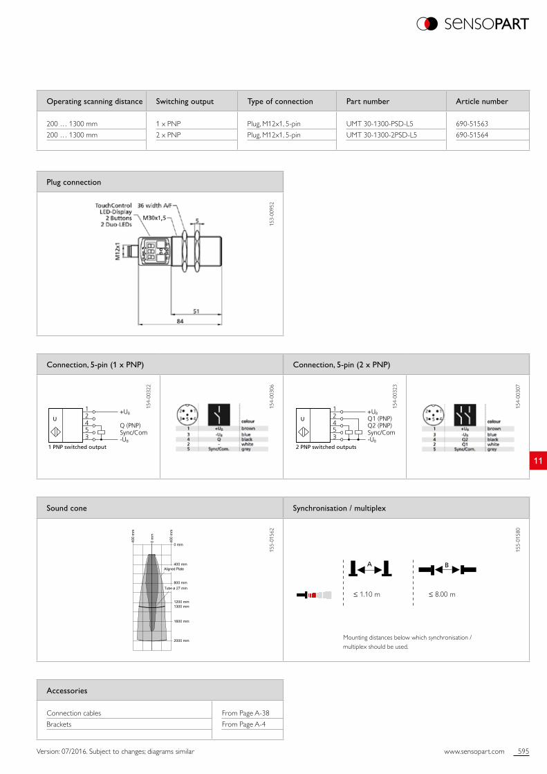
+UB
-UB
Q (PNP)Sync/Com
12453
1 PNP switched output
U+UB
-UB
Q1 (PNP)Q2 (PNP)Sync/Com
12453
2 PNP switched outputs
U
A B
Version: 07/2016. Subject to changes; diagrams similar
Accessories
Connection cables
Brackets
From Page A38
From Page A4
Operating scanning distance Switching output Type of connection Part number Article number
200 … 1300 mm
200 … 1300 mm
1 x PNP
2 x PNP
Plug, M12x1, 5pin
Plug, M12x1, 5pin
UMT 301300PSDL5
UMT 3013002PSDL5
69051563
69051564
Plug connection
153
0095
2
Sound cone Synchronisation / multiplex
155
0156
2
155
0158
0
Connection, 5-pin (1 x PNP) Connection, 5-pin (2 x PNP)
154
0032
2
154
0030
6
154
0032
3
154
0030
7
≤ 1.10 m ≤ 8.00 m
Mounting distances below which synchronisation / multiplex should be used.

596 www.sensopart.com Version: 07/2016. Subject to changes; diagrams similar
Sensor data Functions
Limiting scanning distance
Operating scanning distance
Ultrasonic frequency
Resolution 1
Repeatability
Accuracy3
2000 mm
200 … 1300 mm
~ 200 kHz
0.18 ... 0.57 mm
± 0.15 %2
± 1 % ( Temperature drift internal compensated, may be deactivated, 0.17 % / K without compensation)
Display
LED indicator 1
LED indicator 2
Set analogue characteristic
Teachin modes
Adjustment possibilities
Supplementary functions
Default settings
Parameterisation
Switching output indicator
Switching output indicator
Via Teachin buttons and numerically via 7segment display
Mode 1: set window limits Mode 2: rising / falling output characteristics
Button lock via Teachin button Default settings via Teachin button
– Energysaving Mode – Indicator Mode – Current or voltage output selection – Measurement value filter – Filter strength – Response delay – Foreground suppression – Multiplex Mode, device address – Multiplex Mode, highest address – Measurement range – Calibration display – Detection range, sensitivity
Measurement range: limit scanning distance Window limits, analogue signal: blind zone and scanning distance Switching output: rising analogue characteristic
Electrical data Mechanical data
Operating voltage, +UB
Noload current, I0Current output
Voltage output
Protective circuits
Power On Delay
Analogue output
Response time3
Connection, GY
9 … 30 V DC4
≤ 80 mA
RL ≤ 100 Ω with 9 V ≤ UB ≤ 20 V; RL ≤ 500 Ω with UB ≥ 20 V
RL ≥ 100 kΩ with UB ≥ 15V
Reversepolarity protection, UB / shortcircuit protection (Q)
< 300 ms
0 … 10 V / 4 … 20 mA
92 ms
Sync. / Com.
Dimensions
Enclosure rating
Material, housing
Material, ultrasonic converter
Type of connection
Ambient temperature, operation
Ambient temperature, storage
Weight
Vibration and impact resistance
M30 x 84 mm
IP 675
Brass, nickelplated, plastic content: PBT, TPU
Polyurethane foam, epoxy resin with glass content
(See Selection Table)
25 … +70 °C
40 … +85 °C
150 g
EN 6094752
1 depending on the set analogue window 2 Related to current measurement value 3 Parameterisable via control panel 4 Max. 10 % ripple, within UB 5 With connected IP 67 plug
UMT 30-1300-AUltrasonic sensor with analogue output
PRODUCT HIGHLIGHTS
• Ideal for monitoring the filling levels of liquids such as fats and oils
• Automatic selection to current or voltage output
• Easy presetting of sensor via digital display – sensor immediately ready for operation
• Synchronisation of up to 10 devices in restricted spaces
• Additional features with numerous supplementary functions
597www.sensopart.com
11
Analogue output
+UB
-UB
IU
Sync/Com
12453
U
0 mm
400 mm
800 mm
1200 mm
1600 mm
2000 mm
1300 mm
400
mm
0 m
m
400
mm
Aligned Plate
Tube ø 27 mm
A B
Version: 07/2016. Subject to changes; diagrams similar
Accessories
Connection cables
Brackets
From Page A38
From Page A4
Operating scanning distance Analogue output Type of connection Part number Article number
200 … 1300 mm 0 … 10 V / 4 … 20 mA Plug, M12x1, 5pin UMT 301300AIUDL5 69051562
Plug connection
153
0095
2
Connection, 5-pin
154
0032
4
154
0030
8
Sound cone Synchronisation / multiplex
155
0156
2
155
0158
0
≤ 1.10 m ≤ 8.00 m
Mounting distances below which synchronisation / multiplex should be used.
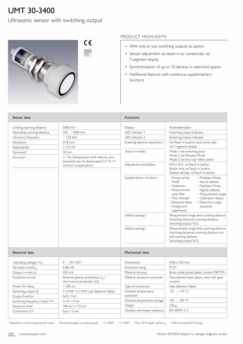
598 www.sensopart.com Version: 07/2016. Subject to changes; diagrams similar
Sensor data Functions
Limiting scanning distance
Operating scanning distance
Ultrasonic frequency
Resolution
Repeatability
Hysteresis2
Accuracy2
5000 mm
350 … 3400 mm
~ 120 kHz
0.18 mm
± 0.15 %1
50 mm
± 1 % ( Temperature drift internal compensated, may be deactivated, 0.17 % / K without compensation)
Display
LED indicator 1
LED indicator 2
Scanning distance adjustment
Teachin modes
Adjustment possibilities
Supplementary functions
Default settings3
Default settings4
Parameterisation
Switching output indicator
Switching output indicator
Via Teachin buttons and numerically via 7segment display
Mode 1: set switching point Mode 2: set Window Mode Mode 3: set twoway reflex switch
N.O. / N.C. via Teachin button Button lock via Teachin button Default settings via Teachin button
– Energysaving Mode – Hysteresis – Measurement value filter – Filter strength – Response delay – Foreground suppression
Measurement range: limit scanning distance Switching distances: scanning distance Switching output: N.O.
Measurement range: limit scanning distance Switching distances: scanning distance and half scanning distance Switching output: N.O.
Electrical data Mechanical data
Operating voltage, +UB
Noload current, I0Output current, Ie
Protective circuits
Power On Delay
Switching output, Q
Output function
Switching frequency, f (ti/tp 1:1)2
Response time2
Connection, GY
9 … 30 V DC5
≤ 80 mA
200 mA
Reversepolarity protection, UB / shortcircuit protection (Q)
< 300 ms
1 x PNP / 2 x PNP (see Selection Table)
N.O. / N.C.
3 Hz3 / 4 Hz4
180 ms3 / 172 ms4
Sync. / Com.
Dimensions
Enclosure rating
Material, housing
Material, ultrasonic converter
Type of connection
Ambient temperature, operation
Ambient temperature, storage
Weight
Vibration and impact resistance
M30 x 102 mm
IP 676
Brass, nickelplated, plastic content: PBT, TPU
Polyurethane foam, epoxy resin with glass content
(See Selection Table)
25 … +70 °C
40 … +85 °C
210 g
EN 6094752
1 Related to current measurement value 2 Parameterisable via control panel 3 1 x PNP 4 2 x PNP 5 Max. 10 % ripple, within UB 6 With connected IP 67 plug
UMT 30-3400Ultrasonic sensor with switching output
PRODUCT HIGHLIGHTS
• With one or two switching outputs as option
• Sensor adjustment via teachin or numerically via 7segment display
• Synchronisation of up to 10 devices in restricted spaces
• Additional features with numerous supplementary functions
– Multiplex Mode, device address – Multiplex Mode, highest address – Measurement range – Calibration display – Detection range, sensitivity
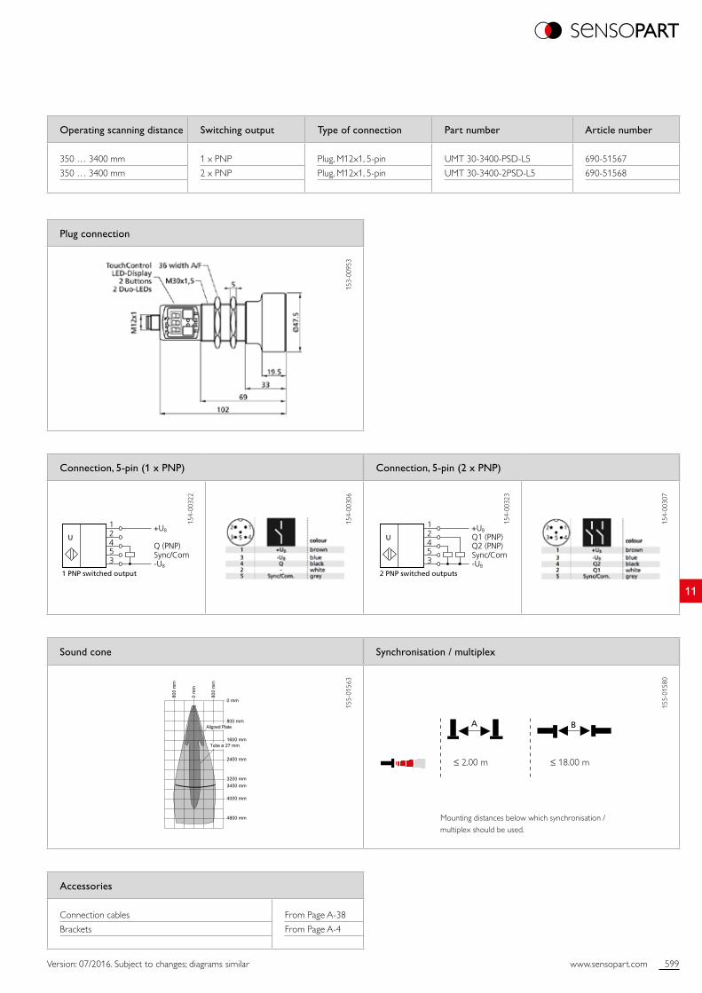
599www.sensopart.com
11
0 mm
800 mm
1600 mm
2400 mm
3200 mm
4000 mm
4800 mm
3400 mm
800
mm
0 m
m
800
mm
Aligned Plate
Tube ø 27 mm
+UB
-UB
Q (PNP)Sync/Com
12453
1 PNP switched output
U+UB
-UB
Q1 (PNP)Q2 (PNP)Sync/Com
12453
2 PNP switched outputs
U
A B
Version: 07/2016. Subject to changes; diagrams similar
Accessories
Connection cables
Brackets
From Page A38
From Page A4
Operating scanning distance Switching output Type of connection Part number Article number
350 … 3400 mm
350 … 3400 mm
1 x PNP
2 x PNP
Plug, M12x1, 5pin
Plug, M12x1, 5pin
UMT 303400PSDL5
UMT 3034002PSDL5
69051567
69051568
Plug connection
153
0095
3
Sound cone Synchronisation / multiplex
155
0156
3
155
0158
0
Connection, 5-pin (1 x PNP) Connection, 5-pin (2 x PNP)
154
0032
2
154
0030
6
154
0032
3
154
0030
7
≤ 2.00 m ≤ 18.00 m
Mounting distances below which synchronisation / multiplex should be used.
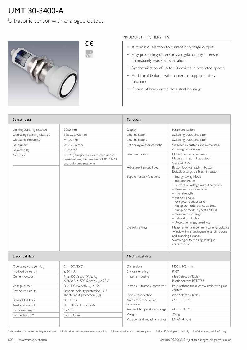
600 www.sensopart.com Version: 07/2016. Subject to changes; diagrams similar
Sensor data Functions
Limiting scanning distance
Operating scanning distance
Ultrasonic frequency
Resolution1
Repeatability
Accuracy3
5000 mm
350 … 3400 mm
~ 120 kHz
0.18 ... 1.5 mm
± 0.15 %2
± 1 % ( Temperature drift internal compensated, may be deactivated, 0.17 % / K without compensation)
Display
LED indicator 1
LED indicator 2
Set analogue characteristic
Teachin modes
Adjustment possibilities
Supplementary functions
Default settings
Parameterisation
Switching output indicator
Switching output indicator
Via Teachin buttons and numerically via 7segment display
Mode 1: set window limits Mode 2: rising / falling output characteristics
Button lock via Teachin button Default settings via Teachin button
– Energysaving Mode – Indicator Mode – Current or voltage output selection – Measurement value filter – Filter strength – Response delay – Foreground suppression – Multiplex Mode, device address – Multiplex Mode, highest address – Measurement range – Calibration display – Detection range, sensitivity
Measurement range: limit scanning distance Window limits, analogue signal: blind zone and scanning distance Switching output: rising analogue characteristic
Electrical data Mechanical data
Operating voltage, +UB
Noload current, I0Current output
Voltage output
Protective circuits
Power On Delay
Analogue output
Response time3
Connection, GY
9 … 30 V DC4
≤ 80 mA
RL ≤ 100 Ω with 9 V ≤ UB ≤ 20 V; RL ≤ 500 Ω with UB ≥ 20 V
RL ≥ 100 kΩ with UB ≥ 15V
Reversepolarity protection, UB / shortcircuit protection (Q)
< 300 ms
0 … 10 V / 4 … 20 mA
172 ms
Sync. / Com.
Dimensions
Enclosure rating
Material, housing
Material, ultrasonic converter
Type of connection
Ambient temperature, operation
Ambient temperature, storage
Weight
Vibration and impact resistance
M30 x 102 mm
IP 675
(See Selection Table) Plastic content: PBT, TPU
Polyurethane foam, epoxy resin with glass content
(See Selection Table)
25 … +70 °C
40 … +85 °C
210 g
EN 6094752
1 depending on the set analogue window 2 Related to current measurement value 3 Parameterisable via control panel 4 Max. 10 % ripple, within UB 5 With connected IP 67 plug
UMT 30-3400-AUltrasonic sensor with analogue output
PRODUCT HIGHLIGHTS
• Automatic selection to current or voltage output
• Easy presetting of sensor via digital display – sensor immediately ready for operation
• Synchronisation of up to 10 devices in restricted spaces
• Additional features with numerous supplementary functions
• Choice of brass or stainless steel housings
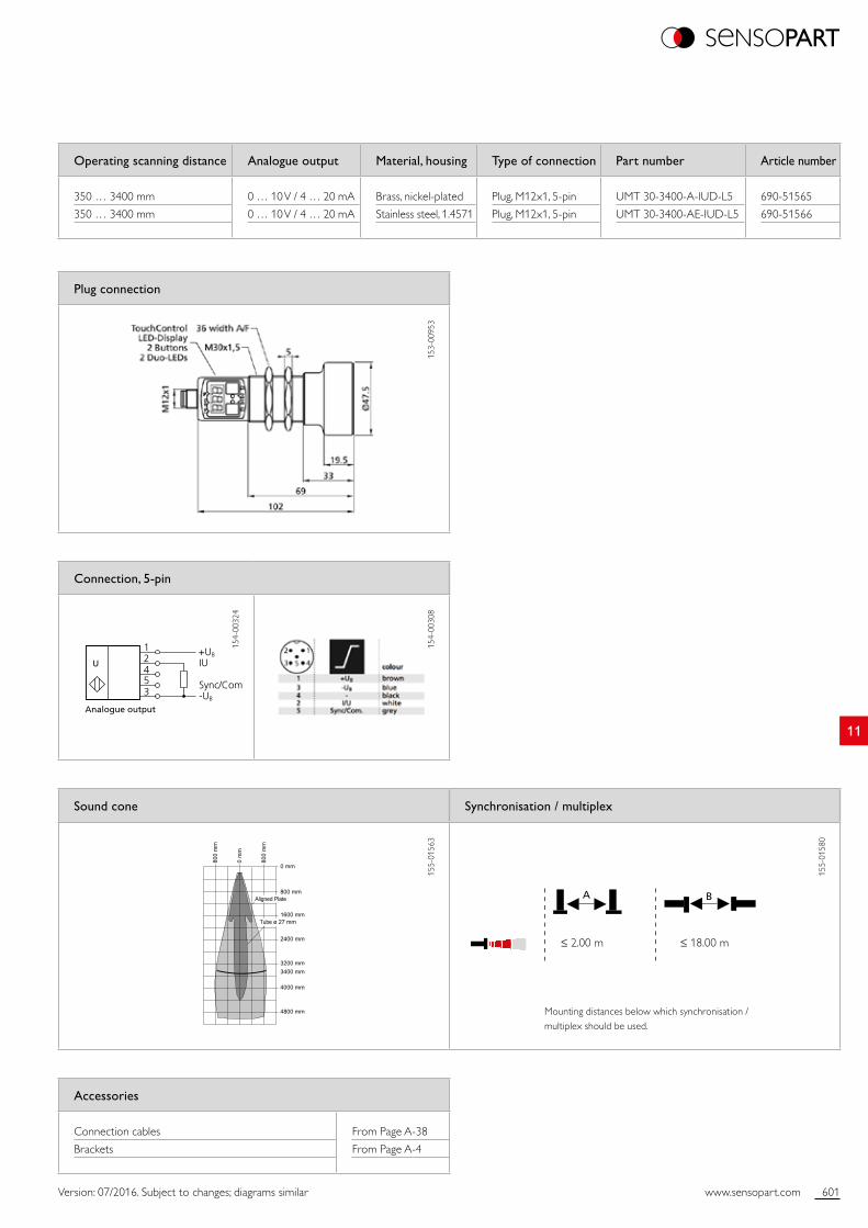
601www.sensopart.com
11
Analogue output
+UB
-UB
IU
Sync/Com
12453
U
0 mm
800 mm
1600 mm
2400 mm
3200 mm
4000 mm
4800 mm
3400 mm
800
mm
0 m
m
800
mm
Aligned Plate
Tube ø 27 mm
A B
Version: 07/2016. Subject to changes; diagrams similar
Accessories
Connection cables
Brackets
From Page A38
From Page A4
Plug connection
153
0095
3
Operating scanning distance Analogue output Material, housing Type of connection Part number Article number
350 … 3400 mm
350 … 3400 mm
0 … 10 V / 4 … 20 mA
0 … 10 V / 4 … 20 mA
Brass, nickelplated
Stainless steel, 1.4571
Plug, M12x1, 5pin
Plug, M12x1, 5pin
UMT 303400AIUDL5
UMT 303400AEIUDL5
69051565
69051566
Connection, 5-pin
154
0032
4
154
0030
8
Sound cone Synchronisation / multiplex
155
0156
3
155
0158
0
≤ 2.00 m ≤ 18.00 m
Mounting distances below which synchronisation / multiplex should be used.
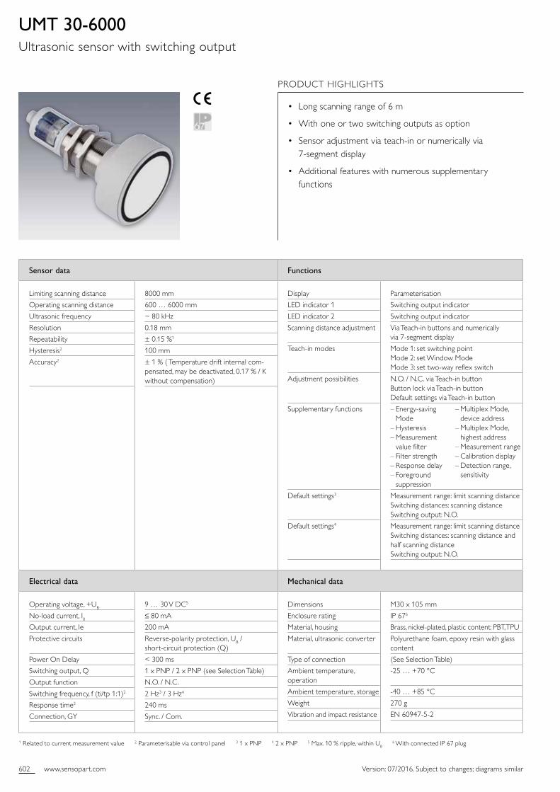
602 www.sensopart.com Version: 07/2016. Subject to changes; diagrams similar
Sensor data Functions
Limiting scanning distance
Operating scanning distance
Ultrasonic frequency
Resolution
Repeatability
Hysteresis2
Accuracy2
8000 mm
600 … 6000 mm
~ 80 kHz
0.18 mm
± 0.15 %1
100 mm
± 1 % ( Temperature drift internal compensated, may be deactivated, 0.17 % / K without compensation)
Display
LED indicator 1
LED indicator 2
Scanning distance adjustment
Teachin modes
Adjustment possibilities
Supplementary functions
Default settings3
Default settings4
Parameterisation
Switching output indicator
Switching output indicator
Via Teachin buttons and numerically via 7segment display
Mode 1: set switching point Mode 2: set Window Mode Mode 3: set twoway reflex switch
N.O. / N.C. via Teachin button Button lock via Teachin button Default settings via Teachin button
– Energysaving Mode – Hysteresis – Measurement value filter – Filter strength – Response delay – Foreground suppression
Measurement range: limit scanning distance Switching distances: scanning distance Switching output: N.O.
Measurement range: limit scanning distance Switching distances: scanning distance and half scanning distance Switching output: N.O.
Electrical data Mechanical data
Operating voltage, +UB
Noload current, I0Output current, Ie
Protective circuits
Power On Delay
Switching output, Q
Output function
Switching frequency, f (ti/tp 1:1)2
Response time2
Connection, GY
9 … 30 V DC5
≤ 80 mA
200 mA
Reversepolarity protection, UB / shortcircuit protection (Q)
< 300 ms
1 x PNP / 2 x PNP (see Selection Table)
N.O. / N.C.
2 Hz3 / 3 Hz4
240 ms
Sync. / Com.
Dimensions
Enclosure rating
Material, housing
Material, ultrasonic converter
Type of connection
Ambient temperature, operation
Ambient temperature, storage
Weight
Vibration and impact resistance
M30 x 105 mm
IP 676
Brass, nickelplated, plastic content: PBT, TPU
Polyurethane foam, epoxy resin with glass content
(See Selection Table)
25 … +70 °C
40 … +85 °C
270 g
EN 6094752
1 Related to current measurement value 2 Parameterisable via control panel 3 1 x PNP 4 2 x PNP 5 Max. 10 % ripple, within UB 6 With connected IP 67 plug
UMT 30-6000Ultrasonic sensor with switching output
PRODUCT HIGHLIGHTS
• Long scanning range of 6 m
• With one or two switching outputs as option
• Sensor adjustment via teachin or numerically via 7segment display
• Additional features with numerous supplementary functions
– Multiplex Mode, device address – Multiplex Mode, highest address – Measurement range – Calibration display – Detection range, sensitivity
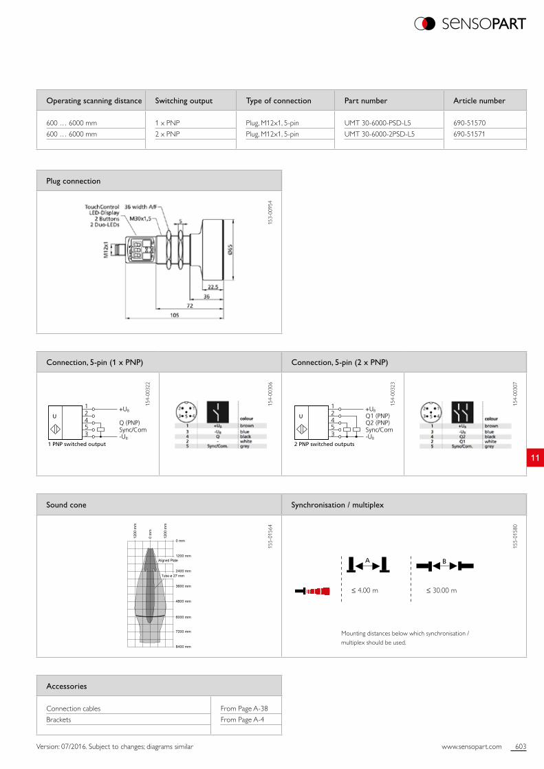
603www.sensopart.com
11
0 mm
1200 mm
2400 mm
3600 mm
4800 mm
6000 mm
7200 mm
8400 mm
1200
mm
0 m
m
1200
mm
Aligned Plate
Tube ø 27 mm
+UB
-UB
Q (PNP)Sync/Com
12453
1 PNP switched output
U+UB
-UB
Q1 (PNP)Q2 (PNP)Sync/Com
12453
2 PNP switched outputs
U
A B
Version: 07/2016. Subject to changes; diagrams similar
Accessories
Connection cables
Brackets
From Page A38
From Page A4
Operating scanning distance Switching output Type of connection Part number Article number
600 … 6000 mm
600 … 6000 mm
1 x PNP
2 x PNP
Plug, M12x1, 5pin
Plug, M12x1, 5pin
UMT 306000PSDL5
UMT 3060002PSDL5
69051570
69051571
Plug connection
153
0095
4
Sound cone Synchronisation / multiplex
155
0156
4
155
0158
0
Connection, 5-pin (1 x PNP) Connection, 5-pin (2 x PNP)
154
0032
2
154
0030
6
154
0032
3
154
0030
7
≤ 4.00 m ≤ 30.00 m
Mounting distances below which synchronisation / multiplex should be used.
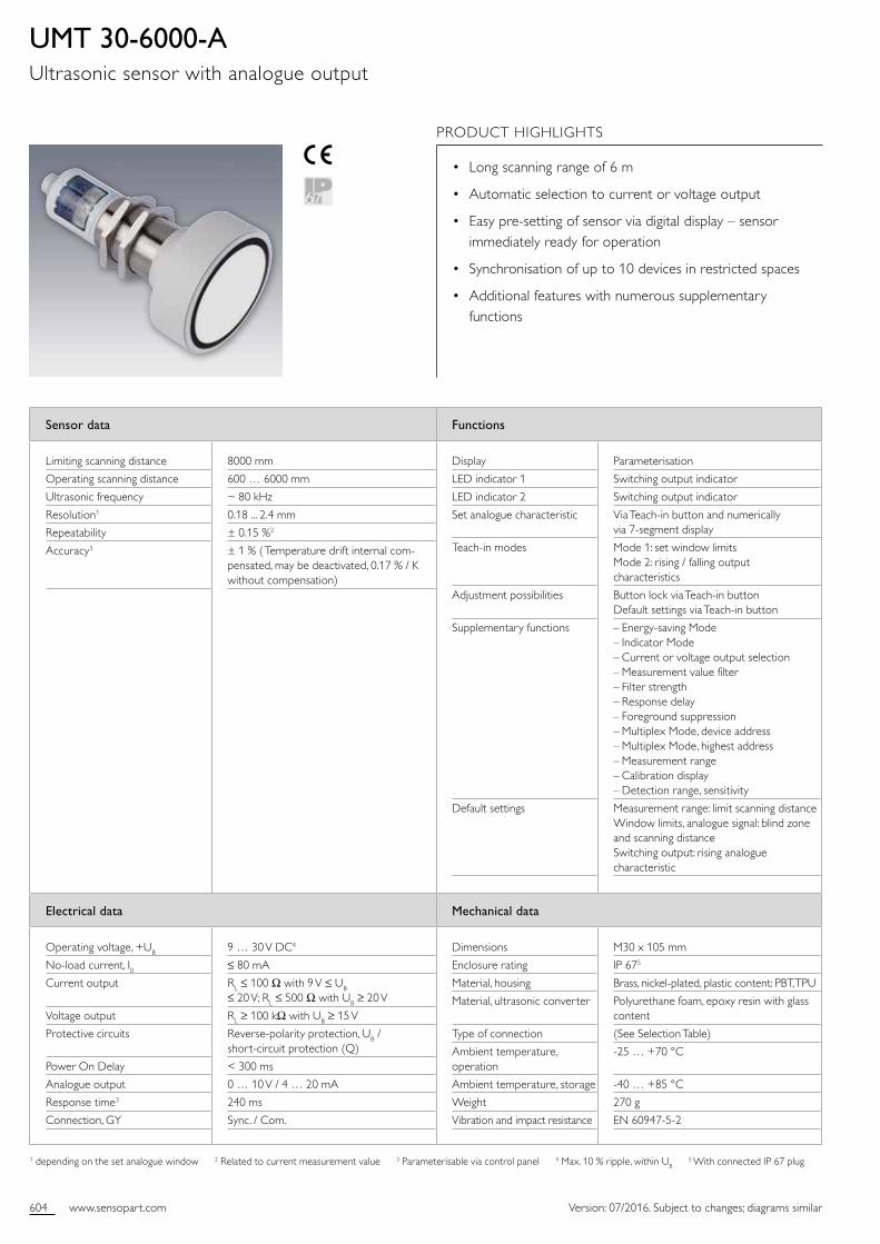
604 www.sensopart.com Version: 07/2016. Subject to changes; diagrams similar
Sensor data Functions
Limiting scanning distance
Operating scanning distance
Ultrasonic frequency
Resolution1
Repeatability
Accuracy3
8000 mm
600 … 6000 mm
~ 80 kHz
0.18 ... 2.4 mm
± 0.15 %2
± 1 % ( Temperature drift internal compensated, may be deactivated, 0.17 % / K without compensation)
Display
LED indicator 1
LED indicator 2
Set analogue characteristic
Teachin modes
Adjustment possibilities
Supplementary functions
Default settings
Parameterisation
Switching output indicator
Switching output indicator
Via Teachin button and numerically via 7segment display
Mode 1: set window limits Mode 2: rising / falling output characteristics
Button lock via Teachin button Default settings via Teachin button
– Energysaving Mode – Indicator Mode – Current or voltage output selection – Measurement value filter – Filter strength – Response delay – Foreground suppression – Multiplex Mode, device address – Multiplex Mode, highest address – Measurement range – Calibration display – Detection range, sensitivity
Measurement range: limit scanning distance Window limits, analogue signal: blind zone and scanning distance Switching output: rising analogue characteristic
Electrical data Mechanical data
Operating voltage, +UB
Noload current, I0Current output
Voltage output
Protective circuits
Power On Delay
Analogue output
Response time3
Connection, GY
9 … 30 V DC4
≤ 80 mA
RL ≤ 100 Ω with 9 V ≤ UB ≤ 20 V; RL ≤ 500 Ω with UB ≥ 20 V
RL ≥ 100 kΩ with UB ≥ 15 V
Reversepolarity protection, UB / shortcircuit protection (Q)
< 300 ms
0 … 10 V / 4 … 20 mA
240 ms
Sync. / Com.
Dimensions
Enclosure rating
Material, housing
Material, ultrasonic converter
Type of connection
Ambient temperature, operation
Ambient temperature, storage
Weight
Vibration and impact resistance
M30 x 105 mm
IP 675
Brass, nickelplated, plastic content: PBT, TPU
Polyurethane foam, epoxy resin with glass content
(See Selection Table)
25 … +70 °C
40 … +85 °C
270 g
EN 6094752
1 depending on the set analogue window 2 Related to current measurement value 3 Parameterisable via control panel 4 Max. 10 % ripple, within UB 5 With connected IP 67 plug
UMT 30-6000-AUltrasonic sensor with analogue output
PRODUCT HIGHLIGHTS
• Long scanning range of 6 m
• Automatic selection to current or voltage output
• Easy presetting of sensor via digital display – sensor immediately ready for operation
• Synchronisation of up to 10 devices in restricted spaces
• Additional features with numerous supplementary functions
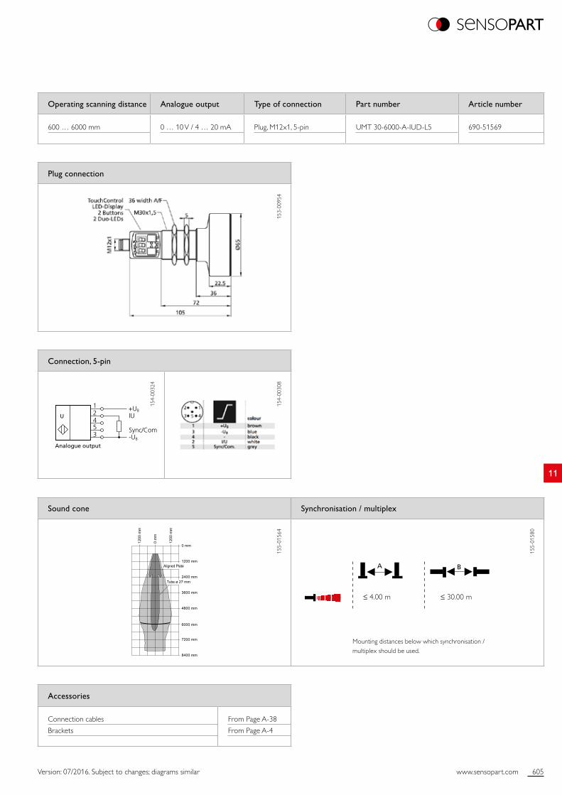
605www.sensopart.com
11
Analogue output
+UB
-UB
IU
Sync/Com
12453
U
0 mm
1200 mm
2400 mm
3600 mm
4800 mm
6000 mm
7200 mm
8400 mm
1200
mm
0 m
m
1200
mm
Aligned Plate
Tube ø 27 mm
A B
Version: 07/2016. Subject to changes; diagrams similar
Accessories
Connection cables
Brackets
From Page A38
From Page A4
Plug connection
153
0095
4
Operating scanning distance Analogue output Type of connection Part number Article number
600 … 6000 mm 0 … 10 V / 4 … 20 mA Plug, M12x1, 5pin UMT 306000AIUDL5 69051569
Connection, 5-pin
154
0032
4
154
0030
8
Sound cone Synchronisation / multiplex
155
0156
4
155
0158
0
≤ 4.00 m ≤ 30.00 m
Mounting distances below which synchronisation / multiplex should be used.
Related Documents