PNNL-14278 Rev. 0 Ultrasonic Examination of Double-Shell Tank 241-AP-101 Examination Completed March 2003 AF Pardini GJ Posakony April 2003 Prepared for the U.S. Department of Energy under Contract DE-AC06-76RL01830

Welcome message from author
This document is posted to help you gain knowledge. Please leave a comment to let me know what you think about it! Share it to your friends and learn new things together.
Transcript

PNNL-14278 Rev. 0
Ultrasonic Examination of Double-Shell Tank 241-AP-101 Examination Completed March 2003 AF Pardini GJ Posakony April 2003 Prepared for the U.S. Department of Energy under Contract DE-AC06-76RL01830
DISCLAIMER This report was prepared as an account of work sponsored by an agency of the United States Government. Neither the United States Government nor any agency thereof, nor Battelle Memorial Institute, nor any of their employees, makes any warranty, express or implied, or assumes any legal liability or responsibility for the accuracy, completeness, or usefulness of any information, apparatus, product, or process disclosed, or represents that its use would not infringe privately owned rights. Reference herein to any specific commercial product, process, or service by trade name, trademark, manufacturer, or otherwise does not necessarily constitute or imply its endorsement, recommendation, or favoring by the United States Government or any agency thereof, or Battelle Memorial Institute. The views and opinions of authors expressed herein do not necessarily state or reflect those of the United States Government or any agency thereof. PACIFIC NORTHWEST NATIONAL LABORATORY operated by BATTELLE for the UNITED STATES DEPARTMENT OF ENERGY under Contract DE-AC06-76RL01830 Printed in the United States of America Available to DOE and DOE contractors from the Office of Scientific and Technical Information, P.O. Box 62, Oak Ridge, TN 37831-0062; ph: (865) 576-8401 fax: (865) 576-5728 email: [email protected] Available to the public from the National Technical Information Service, U.S. Department of Commerce, 5285 Port Royal Rd., Springfield, VA 22161 ph: (800) 553-6847 fax: (703) 605-6900 email: [email protected] online ordering: http://www.ntis.gov/ordering.htm
This document was printed on recycled paper.
(8/00)
iii
Summary COGEMA Engineering Corporation (COGEMA), under a contract from CH2M Hill Hanford Group (CH2M Hill), has performed an ultrasonic examination of selected portions of Double-Shell Tank 241-AP-101. The purpose of this examination was to provide information that could be used to evaluate the integrity of the wall of the primary tank. The requirements for the ultrasonic examination of Tank 241-AP-101 were to detect, characterize (identify, size, and locate), and record measurements made of any wall thinning, pitting, or cracks that might be present in the wall of the primary tank. Any measurements that exceed the requirements set forth in the Engineering Task Plan (ETP), RPP-11832 (Jensen 2002), are reported to CH2M Hill and the Pacific Northwest National Laboratory (PNNL) for further evaluation. Under the contract with CH2M Hill, all data is to be recorded on disk and paper copies of all measurements are provided to PNNL for third-party evaluation. PNNL is responsible for preparing a report(s) that describes the results of the COGEMA ultrasonic examinations.
Examination Results The results of the examination of Tank 241-AP-101 have been evaluated by PNNL personnel. The examination consisted of two 15-in. wide scans over the entire height of the tank, the heat-affected zone (HAZ) of four vertical welds and one horizontal weld, and examination of the knuckle region. The examination was performed to detect any wall thinning, pitting, or cracking in the primary tank wall. Primary Tank Wall Vertical Scan Paths Two 15-in.-wide scan paths were performed on Plates #1, #2, #3, #4, and #5. The plates were examined for wall thinning, pitting, and cracks oriented vertically on the primary tank wall. There were no areas that exceeded the reportable level of 10% of the nominal thickness. No pitting or vertical crack-like indications were detected in Plate #1, #2, #3, #4, or #5. Primary Tank Wall Weld Scan Paths The HAZs of vertical welds in Plates #2, #3, #4, and #5 were examined for wall thinning, pitting and cracks oriented either perpendicular or parallel to the weld. There were no areas that exceeded the reportable level of 10% of the nominal thickness. No pitting or crack-like indications were detected in the weld areas in Plate #2, #3, #4, or #5. The HAZ of the horizontal weld between Plate #5 and the tank knuckle was examined for wall thinning, pitting and cracks oriented either perpendicular or parallel to the weld. There were no areas that exceeded the reportable level of 10% of the nominal thickness. No pitting or crack-like indications were detected in the weld areas on Plate #5 side or on the knuckle side of the horizontal weld.
iv
Primary Tank Wall Knuckle Scan Paths The upper portion of the knuckle area was scanned utilizing the Y-arm scanner attached to the AWS-5D crawler. The Y-arm scanned the transducers down around the knuckle approximately 12-in. from a starting position 2-in. down from the upper knuckle weld joining Plate #5 to the knuckle. The knuckle was examined for wall thinning, pitting, and cracks oriented circumferentially around the primary tank. There were no areas that exceeded the reportable level of 10% of the nominal thickness. No pitting or circumferentially oriented crack-like indications were detected in the upper portion of the knuckle area. Four small areas on the lower portion of the knuckle area were examined for wall thinning only utilizing the Y-arm scanner in areas accessible through selected air slots. The four areas examined were in air slots designated as Slot1, Slot A, Slot B, and Slot D. There were no areas that exceeded the reportable level of 10% of the nominal thickness.
v
Contents 1.0 Introduction................................................................................................................................... 1 2.0 Qualified Personnel, Procedures, and Equipment......................................................................... 2 2.1 Personnel Qualifications....................................................................................................... 2 2.2 Ultrasonic Examination Equipment...................................................................................... 3 2.3 Ultrasonic Examination Procedure ....................................................................................... 3 3.0 Ultrasonic Examination Configuration ......................................................................................... 4 3.1 Primary Tank Wall Transducer Configuration ..................................................................... 4 3.2 Weld Zone Transducer Configuration .................................................................................. 5 3.3 Knuckle Area Transducer Configuration.............................................................................. 7 4.0 Ultrasonic Examination Location ................................................................................................. 9 5.0 Ultrasonic Examination Results.................................................................................................... 11 6.0 Conclusions................................................................................................................................... 15 6.1 Primary Tank Wall Vertical Scan Paths ............................................................................... 15 6.2 Primary Tank Wall Weld Scan Paths ................................................................................... 15 6.2 Primary Tank Wall Knuckle Scan Paths .............................................................................. 16 7.0 References..................................................................................................................................... 17
vi
Figures 3.1 Transducer Configuration for Examining the Primary Tank Wall........................................... 4 3.2 Transducer Configurations for Examination of Welds in the Primary Tank Wall................... 5 3.3 Views of the Weld Zones to be Ultrasonically Examined in the Primary Tank Wall.............. 6 3.4 Sketch of a Section of the Knuckle Examined with the Y-Arm Scanner................................. 7 3.5 Lower Knuckle Examination in Air Slot Regions (End View)................................................ 8 3.6 Lower Knuckle Examination in Air Slot Regions (Side View) ............................................... 8 4.1 UT of 241-AP-101 Riser 31 ..................................................................................................... 9 4.2 Sketch of Scan Paths on Tank 241-AP-101 ............................................................................. 10 5.1 UT Data from Tank 241-AP-101 ............................................................................................. 12 5.2 UT Data from Tank 241-AP-101 cont. .................................................................................... 13 5.3 UT Data from Tank 241-AP-101 cont. .................................................................................... 14
1
1.0 Introduction COGEMA Engineering Corporation (COGEMA), under a contract from CH2M Hill Hanford Group (CH2M Hill), has performed an ultrasonic examination (UT) of selected portions of Double-Shell Tank (DST) 241-AP-101. The purpose of this examination was to provide information that could be used to evaluate the integrity of the DST. The requirements for the UT of Tank 241-AP-101 were to detect, characterize (identify, size, and locate), and record measurements made of any wall thinning, pitting, or cracks that might be present in the wall of the primary tank. Any measurements that exceed the requirements set forth in the Engineering Task Plan (ETP), RPP-11832 (Jensen 2002), are reported to CH2M Hill and the Pacific Northwest National Laboratory (PNNL) for further evaluation. Specific measurements that are reported include the following: • Wall thinning that exceeds 10% of the nominal thickness of the plate. • Pits with depths that exceed 25% of the nominal plate thickness. • Stress-corrosion cracks that exceed 0.10-in. (through-wall) that are detected in the inner wall of the
tank, heat-affected zone (HAZ) of welds, or in the tank knuckle. The accuracy requirements for ultrasonic measurements for the different types of defects are as follows: • Wall thinning – measure thickness within ±0.020-in. • Pits – size depths within ±0.050-in. • Cracks – size the depth of cracks on the inner wall surfaces within ±0.1-in. • Location – locate all reportable indications within ±1.0-in.
Under the contract with CH2M Hill, all data is to be recorded on disk and paper copies of all measurements are provided to PNNL for third-party evaluation. PNNL is responsible for preparing a report(s) that describes the results of the COGEMA UT.
2
2.0 Qualified Personnel, Procedures, and Equipment Under contract from CH2M Hill, qualification of personnel participating in the DST inspection program, the UT equipment (instrument and mechanical scanning fixture), and the UT procedure that will be used in the examination of the current DST is required. Personnel participating in the examinations are to be certified in accordance with American Society for Nondestructive Testing (ASNT) Guideline SNT-TC-1A-92 and associated documentation is to be provided. The capability of the UT system is to be validated through a performance demonstration test (PDT) administered by PNNL on a mock-up simulating the actual DST. The current procedure for the UT is to be based on the Section V, Article 4, Boiler and Pressure Vessel Code defined by the American Society for Mechanical Engineers (ASME). 2.1 Personnel Qualifications The following individuals were qualified and certified to perform UT of the Hanford DST 241-AP-101: • Mr. Wesley Nelson, ASNT Level III (#LM-1874) in UT, has been identified as COGEMA’s UT
Level III authority for this project. Mr. Nelson has been certified by COGEMA as a UT Level III in accordance with COGEMA procedure COGEMA-SVCP-PRC-014, latest revision. Further documentation has been provided to establish his qualifications. Reference: Letter from PNNL to C.E. Jensen dated August 22, 2000, “Report on Performance Demonstration Test – PDT, May 2000.”
• Mr. James B. Elder, ASNT Level III (#JM-1891) in UT, has been contracted by COGEMA to
provide peer review of all DST UT data. Mr. Elder has been certified by JBNDT as a UT Level III in accordance with JBNDT written practice JBNDT-WP-1, latest revision. Further documentation has been provided to establish his qualifications. Reference: PNNL-11971, Final Report - Ultrasonic Examination of Double-Shell Tank 241-AN-107.
• Mr. William D. Purdy, COGEMA UT Level II limited (for P-Scan data acquisition only).
Mr. Purdy has been certified in accordance with COGEMA procedure COGEMA-SVCP-PRC-014, latest revision. Further documentation has been provided to establish his qualifications. Reference: Letter from PNNL to C.E. Jensen dated October 5, 2001, “Purdy Performance Demonstration Test (PDT) Report.”
3
2.2 Ultrasonic Examination Equipment CH2M Hill has provided the UT equipment for the examination of Tank 241-AP-101. This equipment consists of a Force Institute P-Scan ultrasonic test instrument and a Force Institute AWS-5D remote-controlled, magnetic-wheel crawler for examining the primary tank wall. The examination of Tank 241-AP-101 also included utilization of the Y-arm scanning bridge. Ultrasonic transducers used for the examinations are commercial off the shelf. The P-Scan ultrasonic system and Y-arm scanner attachment have been qualified through a PDT administered by PNNL. Reference: PNNL-11971, Final Report- Ultrasonic Examination of Double-Shell Tank 241-AN-107 and letter from PNNL to C.E. Jensen dated September 21, 2001, “Qualification of the Y-Arm Attachment”. 2.3 Ultrasonic Examination Procedure COGEMA has provided the UT procedure for the examination of Tank 241-AP-101. This procedure, COGEMA-SVUT-INS-007.3, Revision 1, outlines the type of UT and mechanical equipment that are to be used as well as the types of transducers. Both straight-beam and angle-beam transducers are used for the examination of the primary tank wall. The examination procedures include full documentation on methods for calibration, examination, and reporting. Hard copies of the T-Scan (thickness) and P-Scan (projection or angle beam) views of all areas scanned are made available for analysis. The UT procedure requires the use of specific UT transducers for the different examinations. A calibration performed before and after the examinations identifies the specific transducers used and the sensitivity adjustments needed to perform the inspection. The COGEMA UT procedure has been qualified through a Performance Demonstration Test. Reference: PNNL-11971, Final Report - Ultrasonic Examination of Double-Shell Tank 241-AN-107.
4
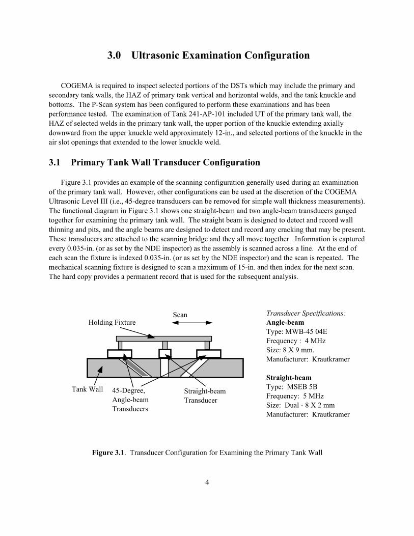
3.0 Ultrasonic Examination Configuration COGEMA is required to inspect selected portions of the DSTs which may include the primary and secondary tank walls, the HAZ of primary tank vertical and horizontal welds, and the tank knuckle and bottoms. The P-Scan system has been configured to perform these examinations and has been performance tested. The examination of Tank 241-AP-101 included UT of the primary tank wall, the HAZ of selected welds in the primary tank wall, the upper portion of the knuckle extending axially downward from the upper knuckle weld approximately 12-in., and selected portions of the knuckle in the air slot openings that extended to the lower knuckle weld. 3.1 Primary Tank Wall Transducer Configuration Figure 3.1 provides an example of the scanning configuration generally used during an examination of the primary tank wall. However, other configurations can be used at the discretion of the COGEMA Ultrasonic Level III (i.e., 45-degree transducers can be removed for simple wall thickness measurements). The functional diagram in Figure 3.1 shows one straight-beam and two angle-beam transducers ganged together for examining the primary tank wall. The straight beam is designed to detect and record wall thinning and pits, and the angle beams are designed to detect and record any cracking that may be present. These transducers are attached to the scanning bridge and they all move together. Information is captured every 0.035-in. (or as set by the NDE inspector) as the assembly is scanned across a line. At the end of each scan the fixture is indexed 0.035-in. (or as set by the NDE inspector) and the scan is repeated. The mechanical scanning fixture is designed to scan a maximum of 15-in. and then index for the next scan. The hard copy provides a permanent record that is used for the subsequent analysis.
Figure 3.1. Transducer Configuration for Examining the Primary Tank Wall
45-Degree,Angle-beamTransducers
Straight-beamTransducer
Tank Wall
Transducer Specifications:Angle-beamType: MWB-45 04EFrequency : 4 MHzSize: 8 X 9 mm.Manufacturer: Krautkramer
Straight-beamType: MSEB 5BFrequency: 5 MHzSize: Dual - 8 X 2 mmManufacturer: Krautkramer
Holding Fixture
Scan andIndex
Scan
5
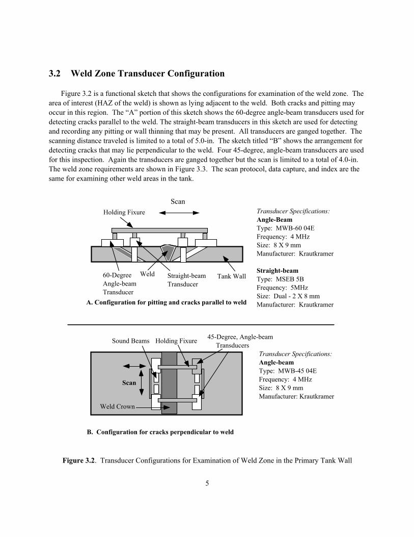
3.2 Weld Zone Transducer Configuration Figure 3.2 is a functional sketch that shows the configurations for examination of the weld zone. The area of interest (HAZ of the weld) is shown as lying adjacent to the weld. Both cracks and pitting may occur in this region. The “A” portion of this sketch shows the 60-degree angle-beam transducers used for detecting cracks parallel to the weld. The straight-beam transducers in this sketch are used for detecting and recording any pitting or wall thinning that may be present. All transducers are ganged together. The scanning distance traveled is limited to a total of 5.0-in. The sketch titled “B” shows the arrangement for detecting cracks that may lie perpendicular to the weld. Four 45-degree, angle-beam transducers are used for this inspection. Again the transducers are ganged together but the scan is limited to a total of 4.0-in. The weld zone requirements are shown in Figure 3.3. The scan protocol, data capture, and index are the same for examining other weld areas in the tank.
Figure 3.2. Transducer Configurations for Examination of Weld Zone in the Primary Tank Wall
Holding Fixure
60-DegreeAngle-beamTransducer
Straight-beamTransducer
Tank Wall
Transducer Specifications:Angle-BeamType: MWB-60 04EFrequency: 4 MHzSize: 8 X 9 mmManufacturer: Krautkramer
Straight-beamType: MSEB 5BFrequency: 5MHzSize: Dual - 2 X 8 mmManufacturer: Krautkramer
Weld
Scan
Scan
Holding FixureSound Beams
Weld Crown
Transducer Specifications:Angle-beamType: MWB-45 04EFrequency: 4 MHzSize: 8 X 9 mmManufacturer: Krautkramer
A. Configuration for pitting and cracks parallel to weld
45-Degree, Angle-beam Transducers
B. Configuration for cracks perpendicular to weld
Scan
6
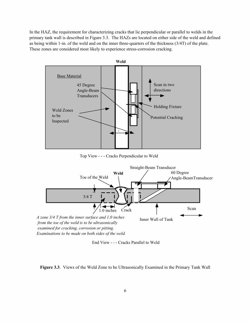
In the HAZ, the requirement for characterizing cracks that lie perpendicular or parallel to welds in the primary tank wall is described in Figure 3.3. The HAZs are located on either side of the weld and defined as being within 1-in. of the weld and on the inner three-quarters of the thickness (3/4T) of the plate. These zones are considered most likely to experience stress-corrosion cracking.
Figure 3.3. Views of the Weld Zone to be Ultrasonically Examined in the Primary Tank Wall
Base Material
Weld Zonesto beInspected
Weld
Top View - - - Cracks Perpendicular to Weld
Inner Wall of Tank
WeldToe of the Weld
End View - - - Cracks Parallel to Weld
A zone 3/4 T from the inner surface and 1.0 inches from the toe of the weld is to be ultrasonically examined for cracking, corrosion or pitting.Examinations to be made on both sides of the weld.
1.0 inches
3/4 T
60 DegreeAngle-BeamTransducer
Scan in twodirections
Potential Cracking
Crack
Straight-Beam Transducer
45 DegreeAngle-BeamTransducers
Scan in twodirections
Holding Fixture
Scan
7
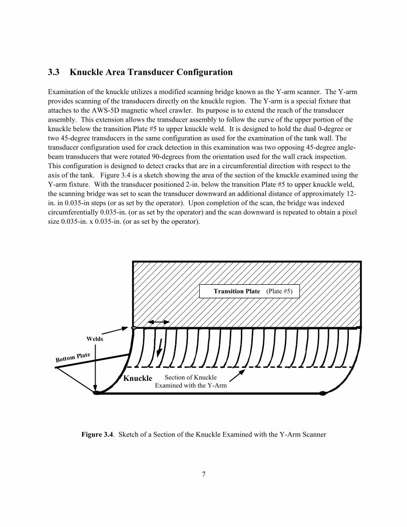
3.3 Knuckle Area Transducer Configuration Examination of the knuckle utilizes a modified scanning bridge known as the Y-arm scanner. The Y-arm provides scanning of the transducers directly on the knuckle region. The Y-arm is a special fixture that attaches to the AWS-5D magnetic wheel crawler. Its purpose is to extend the reach of the transducer assembly. This extension allows the transducer assembly to follow the curve of the upper portion of the knuckle below the transition Plate #5 to upper knuckle weld. It is designed to hold the dual 0-degree or two 45-degree transducers in the same configuration as used for the examination of the tank wall. The transducer configuration used for crack detection in this examination was two opposing 45-degree angle-beam transducers that were rotated 90-degrees from the orientation used for the wall crack inspection. This configuration is designed to detect cracks that are in a circumferential direction with respect to the axis of the tank. Figure 3.4 is a sketch showing the area of the section of the knuckle examined using the Y-arm fixture. With the transducer positioned 2-in. below the transition Plate #5 to upper knuckle weld, the scanning bridge was set to scan the transducer downward an additional distance of approximately 12-in. in 0.035-in steps (or as set by the operator). Upon completion of the scan, the bridge was indexed circumferentially 0.035-in. (or as set by the operator) and the scan downward is repeated to obtain a pixel size 0.035-in. x 0.035-in. (or as set by the operator).
Figure 3.4. Sketch of a Section of the Knuckle Examined with the Y-Arm Scanner
Transition Plate
Welds
Knuckle Section of KnuckleExamined with the Y-Arm
Bottom Plate
(Plate #5)
8
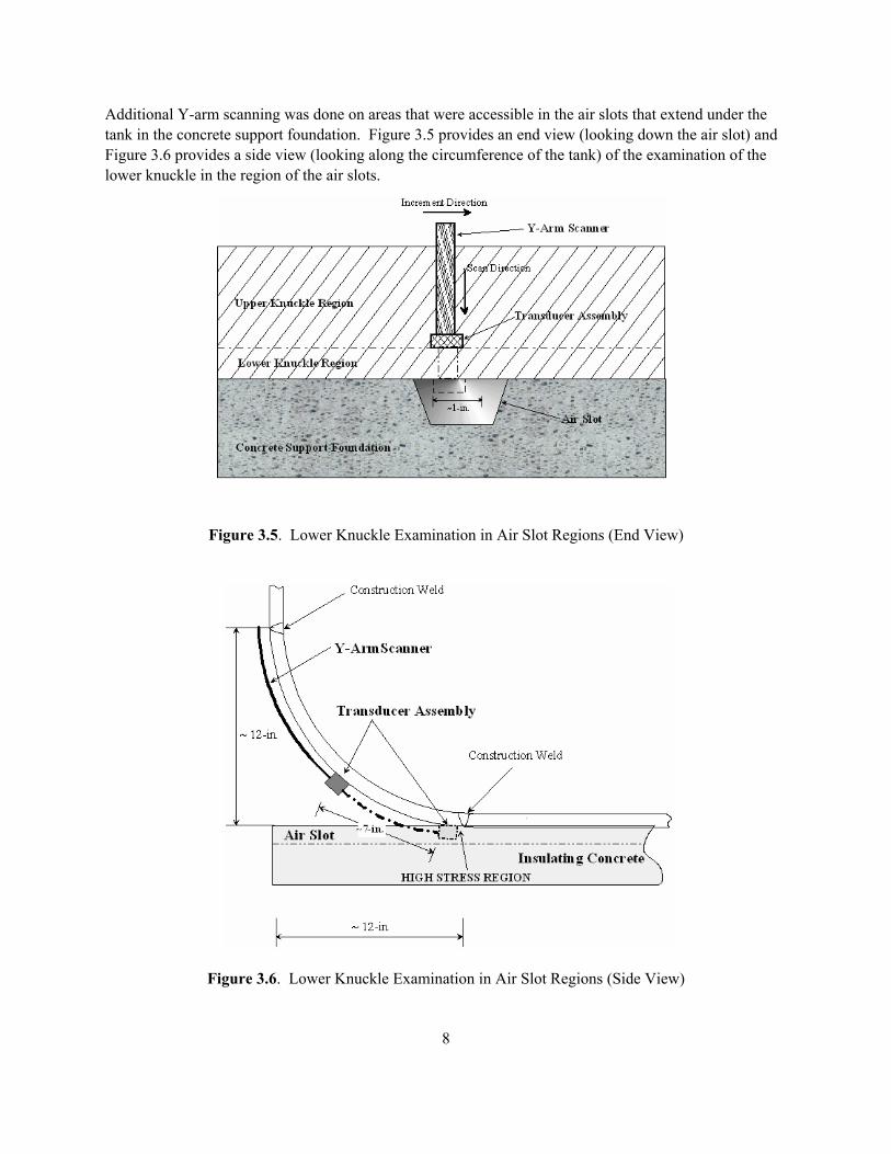
Additional Y-arm scanning was done on areas that were accessible in the air slots that extend under the tank in the concrete support foundation. Figure 3.5 provides an end view (looking down the air slot) and Figure 3.6 provides a side view (looking along the circumference of the tank) of the examination of the lower knuckle in the region of the air slots.
Figure 3.5. Lower Knuckle Examination in Air Slot Regions (End View)
Figure 3.6. Lower Knuckle Examination in Air Slot Regions (Side View)
9
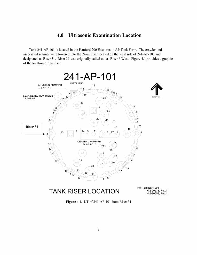
4.0 Ultrasonic Examination Location Tank 241-AP-101 is located in the Hanford 200 East area in AP Tank Farm. The crawler and associated scanner were lowered into the 24-in. riser located on the west side of 241-AP-101 and designated as Riser 31. Riser 31 was originally called out as Riser 6 West. Figure 4.1 provides a graphic of the location of this riser.
Figure 4.1. UT of 241-AP-101 from Riser 31
241-AP-01B
241-AP-01A
TANK RISER LOCATION H-2-90553, Rev.4H-2-90538, Rev.1
Ref: Salazar 1994
241-AP-101
241-AP-01LEAK DETECTION RISER
INSTR ENCLANNULUS PUMP PIT
CENTRAL PUMP PIT
7
1
16
28
19
17
23
9817
17
19 17
8
314
22
13 5
1
16
6
17
9817
1923
1720
17
8
11
26
727
415
1021
18
8 17
1719
89
17
17
12 27 116
2
5
27
25
10
24
6
23
817
19
17
178919
17
18
Riser 31
10
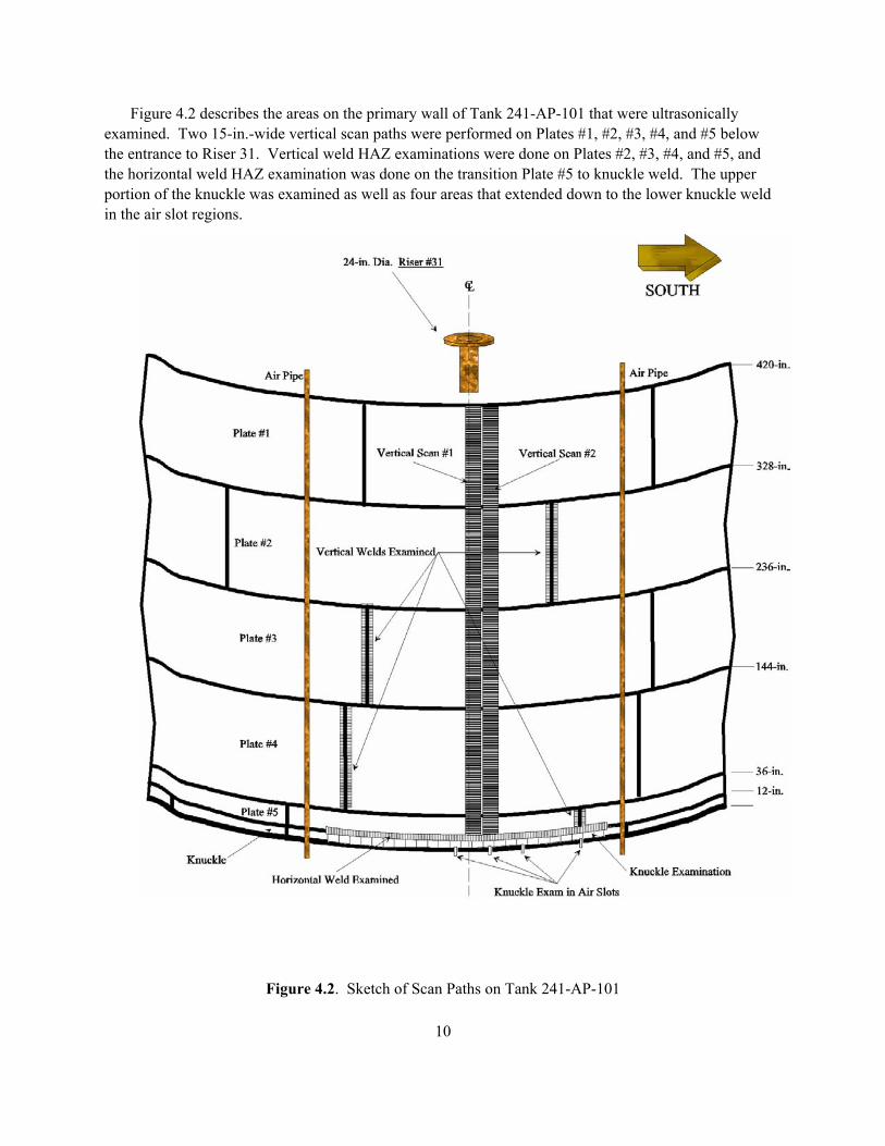
Figure 4.2 describes the areas on the primary wall of Tank 241-AP-101 that were ultrasonically examined. Two 15-in.-wide vertical scan paths were performed on Plates #1, #2, #3, #4, and #5 below the entrance to Riser 31. Vertical weld HAZ examinations were done on Plates #2, #3, #4, and #5, and the horizontal weld HAZ examination was done on the transition Plate #5 to knuckle weld. The upper portion of the knuckle was examined as well as four areas that extended down to the lower knuckle weld in the air slot regions.
Figure 4.2. Sketch of Scan Paths on Tank 241-AP-101
11
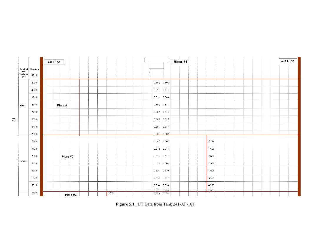
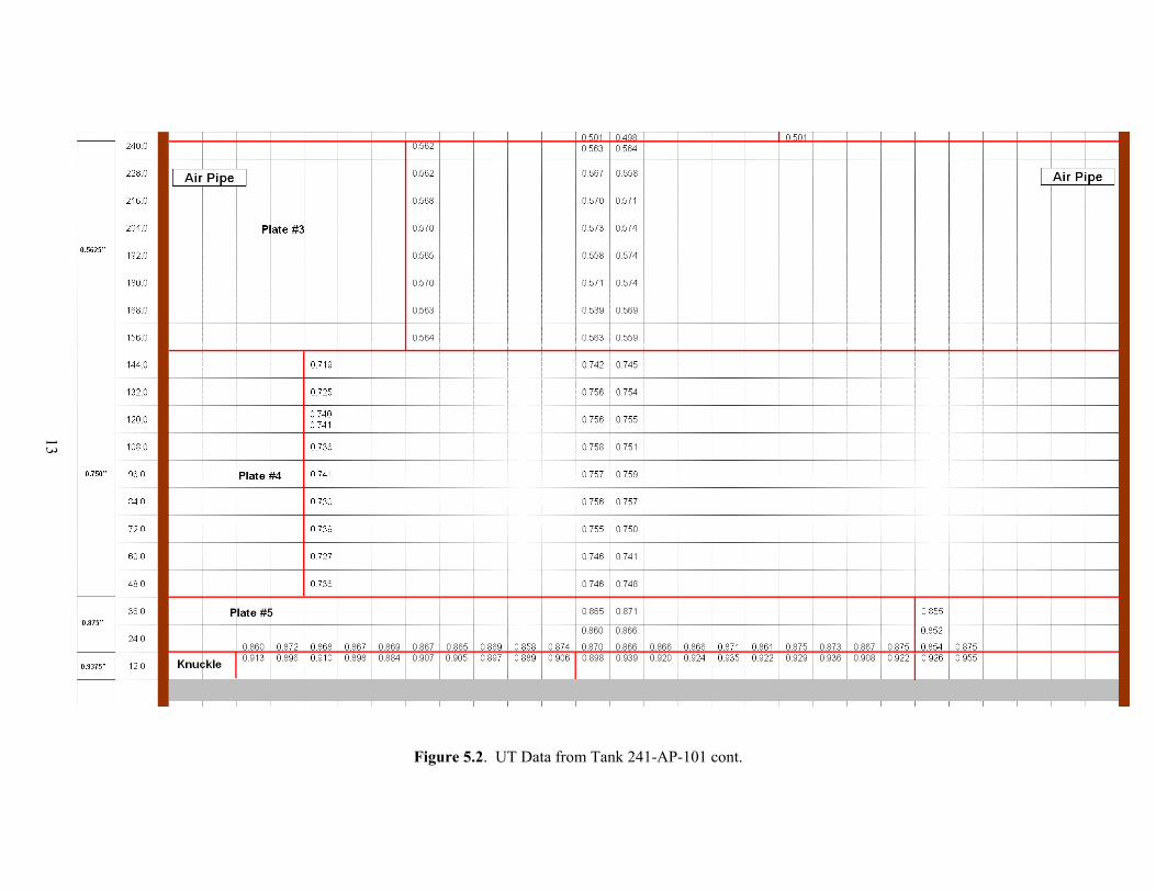
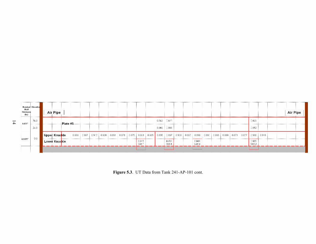
5.0 Ultrasonic Examination Results COGEMA has provided detailed reports including T-Scan and P-Scan hard copies of all areas that were ultrasonically examined to PNNL for third-party review. The data was analyzed by COGEMA Level III Mr. Wes Nelson and peer reviewed by JBNDT Level III Mr. Jim Elder. The results of the examination of Tank 241-AP-101 are presented in Figures 5.1, 5.2, and 5.3. Figures 5.1 and 5.2 show the examination of the primary tank wall and the HAZs of both vertical and horizontal welds. The examination consisted of two vertical paths beneath the 24-in. diameter riser. Vertical scan #1 was 15-in. wide on Plates #1, #2, #3, #4, and #5 and was directly below the 24-in riser. Vertical scan #2 was adjacent to vertical scan #1 and was also 15-in. wide on Plates #1, #2, #3, #4, and #5. The HAZs of vertical welds in Plates #2, #3, #4, and #5 were examined and the HAZ in the horizontal weld between Plate #5 and the Knuckle section were also examined. Areas in the figures that show two measurements in the same box are the result of the vertical scan paths overlapping the horizontal HAZ scan paths or where the inspectors started a new scan and overlapped a previous scan. Figures 5.1 and 5.2 display the minimum reading taken in each 15-in. wide by 12-in. long portion of the scan. In the overlapping areas, both minimum readings from each of vertical and horizontal scan paths are given. Figure 5.3 shows the examination performed on the knuckle of the primary tank wall. The readings distributed around the circumference of the tank knuckle represent the minimum reading in each 12-in. long by 12-in. wide portion extending down around the knuckle. The four areas denoted as Slot 1, Slot A, Slot B, and Slot D, represent small areas that were scanned extending down to the lower knuckle weld in the air slots. These scan areas are approximately 1-in. long (increment direction around the circumference of the tank), and 7-in wide (scan direction is down around the knuckle and into the air slot) as shown previously in Section 3 of this report.
12
Figure 5.1. UT Data from Tank 241-AP-101
13
Figure 5.2. UT Data from Tank 241-AP-101 cont.
14
Figure 5.3. UT Data from Tank 241-AP-101 cont.
15
6.0 Conclusions The results of the examination of Tank 241-AP-101 have been evaluated by PNNL personnel. The examination consisted of two 15-in. wide scans over the entire height of the tank, the HAZs of 4 vertical welds and 1 horizontal weld, and examination of the knuckle region. The examination was performed to detect any wall thinning, pitting, or cracking in the primary tank wall. 6.1 Primary Tank Wall Vertical Scan Paths Two 15-in.-wide scan paths were performed on Plates #1, #2, #3, #4, and #5. The plates were examined for wall thinning, pitting, and cracks oriented vertically on the primary tank wall. The results indicated that the minimum thicknesses in the areas scanned with nominal thickness of 0.500-in. were as follows; Plate #1 was 0.492-in. and Plate #2 was 0.498-in. The nominal thickness in Plate #3 is 0.5625-in. and the minimum thickness in this area was 0.539-in. The nominal thickness in Plate #4 is 0.750-in. and the minimum thickness in this area was 0.741-in. The nominal thickness in Plate #5 is 0.875-in. and the minimum thickness in this area was 0.860-in. There were no areas that exceeded the reportable level of 10% of the nominal thickness. No pitting or vertical crack-like indications were detected in Plate #1, #2, #3, #4, or #5. 6.2 Primary Tank Wall Weld Scan Paths The HAZs of vertical welds in Plates #2, #3, #4, and #5 were examined for wall thinning, pitting and cracks oriented either perpendicular or parallel to the weld. The results indicated that the minimum thicknesses in the weld areas scanned were as follows: The nominal thickness of Plate #2 is 0.500-in. and the minimum thickness in this weld area was 0.499-in. The nominal thickness in Plate #3 is 0.5625-in. and the minimum thickness in this weld area was 0.562-in. The nominal thickness in Plate #4 is 0.750-in. and the minimum thickness in this weld area was 0.719-in. The nominal thickness in Plate #5 is 0.875-in. and the minimum thickness in this weld area was 0.852-in. There were no areas that exceeded the reportable level of 10% of the nominal thickness. No pitting or crack-like indications were detected in the weld areas in Plate #2, #3, #4, or #5. The HAZ of the horizontal weld between Plate #5 and the tank knuckle was examined for wall thinning, pitting and cracks oriented either perpendicular or parallel to the weld. The results indicated that the minimum thickness in the weld area with nominal thickness of 0.875-in. on Plate #5 was 0.854-in. The minimum thickness in the weld area with nominal thickness of 0.9375-in. on the knuckle was 0.884-in. There were no areas that exceeded the reportable level of 10% of the nominal thickness. No pitting or crack-like indications were detected in the weld areas on Plate #5 side or on the knuckle side of the horizontal weld.
16
6.3 Primary Tank Wall Knuckle Scan Paths The upper portion of the knuckle area was scanned utilizing the Y-arm scanner attached to the AWS-5D crawler. The Y-arm scanned the transducers down around the knuckle approximately 12-in. from a starting position 2-in. down from the upper knuckle weld joining Plate #5 to the knuckle. The knuckle was examined for wall thinning, pitting, and cracks oriented circumferentially around the primary tank. The results indicated that the minimum thickness in the approximately 20 circumferential feet of knuckle area examined with nominal thickness of 0.9375-in. was 0.880-in. There were no areas that exceeded the reportable level of 10% of the nominal thickness. No pitting or circumferentially oriented crack-like indications were detected in the upper portion of the knuckle area. Four small areas on the lower portion of the knuckle area were examined for wall thinning only utilizing the Y-arm scanner in areas accessible through selected air slots. The four areas examined were in air slots designated as Slot1, Slot A, Slot B, and Slot D. The results indicated that the minimum thickness in the lower portion of the knuckle area, with nominal thickness of 0.9375-in., in the selected air slots was 0.944-in. There were no areas that exceeded the reportable level of 10% of the nominal thickness.
17
7.0 References Jensen, C. E., 2002, Engineering Task Plan for the Ultrasonic Inspection of Hanford Double-Shell Tanks FY2003, RPP-11832, Rev 0, September 2002, CH2M Hill Hanford Group, Inc., Richland, Washington.
Distr-1
Distribution No. of Copies Offsite 4 DOE/Office of Scientific and Technical Information & Information Release 1 DOE Office of Science and
Technology Kurt Gerdes 1154 Cloverleaf Building 19901 Germantown Road Germantown, MD 20874-1290
Onsite 4 Hanford Site J. L. Castleberry (1) R3-76 G. P. Duncan (1) R3-76 C. E. Jensen (2) R3-76 10 Pacific Northwest National Laboratory
M. T. Anderson (1) K5-26 J. W. Brothers (1) K7-15 L. O. Casazza (1) K5-26 A. F. Pardini (6) K5-26 G. J. Posakony (1) K5-26
Related Documents