Ultrahigh-Q mechanical oscillators through optical trapping This article has been downloaded from IOPscience. Please scroll down to see the full text article. 2012 New J. Phys. 14 045002 (http://iopscience.iop.org/1367-2630/14/4/045002) Download details: IP Address: 131.215.237.47 The article was downloaded on 09/06/2012 at 15:42 Please note that terms and conditions apply. View the table of contents for this issue, or go to the journal homepage for more Home Search Collections Journals About Contact us My IOPscience

Welcome message from author
This document is posted to help you gain knowledge. Please leave a comment to let me know what you think about it! Share it to your friends and learn new things together.
Transcript

Ultrahigh-Q mechanical oscillators through optical trapping
This article has been downloaded from IOPscience. Please scroll down to see the full text article.
2012 New J. Phys. 14 045002
(http://iopscience.iop.org/1367-2630/14/4/045002)
Download details:
IP Address: 131.215.237.47
The article was downloaded on 09/06/2012 at 15:42
Please note that terms and conditions apply.
View the table of contents for this issue, or go to the journal homepage for more
Home Search Collections Journals About Contact us My IOPscience
T h e o p e n – a c c e s s j o u r n a l f o r p h y s i c s
New Journal of Physics
Ultrahigh-Q mechanical oscillators throughoptical trapping
D E Chang1,2,5, K-K Ni1,3, O Painter1,4 and H J Kimble1,3
1 Institute for Quantum Information and Matter, California Institute ofTechnology, Pasadena, CA 91125, USA2 ICFO—Institut de Ciencies Fotoniques, Mediterranean Technology Park,08860 Castelldefels (Barcelona), Spain3 Norman Bridge Laboratory of Physics 12-33, California Institute ofTechnology, Pasadena, CA 91125, USA4 Thomas J Watson, Sr, Laboratory of Applied Physics, California Instituteof Technology, Pasadena, CA 91125, USAE-mail: [email protected]
New Journal of Physics 14 (2012) 045002 (19pp)Received 24 October 2011Published 2 April 2012Online at http://www.njp.org/doi:10.1088/1367-2630/14/4/045002
Abstract. Rapid advances are being made toward optically cooling a singlemode of a micro-mechanical system to its quantum ground state and observingthe quantum behavior at macroscopic scales. Reaching this regime in room-temperature environments requires a stringent condition on the mechanicalquality factor Qm and frequency fm, Qm fm & kBTbath/h, which so far has beenmarginally satisfied only in a small number of systems. Here we propose andanalyze a new class of systems that should enable one to obtain unprecedentedQ-frequency products. The technique is based on the use of optical forces to‘trap’ and stiffen the motion of a tethered mechanical structure, thereby freeingthe resulting mechanical frequencies and decoherence rates from the underlyingmaterial properties.
5 Author to whom any correspondence should be addressed.
New Journal of Physics 14 (2012) 0450021367-2630/12/045002+19$33.00 © IOP Publishing Ltd and Deutsche Physikalische Gesellschaft

2
Contents
1. Enhancing quality factors through optical trapping 42. A membrane in a cavity: modification of modes and recoil heating 83. Comparison of optical trapping schemes 114. Conclusion and outlook 13Acknowledgments 13Appendix A. Derivation of the membrane equation 14Appendix B. Thermoelastic damping 15Appendix C. Modification of opto-mechanical coupling strengths 15Appendix D. Quantum opto-mechanics with a tethered membrane 16References 17
The coupling of a high-Q mode of a micro-mechanical oscillator to an optical cavity hasemerged as a promising route toward observing quantum behavior at macroscopic scales [1].This opto-mechanical interaction is being used, for example, to optically cool a mechanicalmode toward its quantum ground state [1–3]. Ground-state cooling requires that the product ofthe quality factor Qm and the frequency fm of the mechanical mode exceed kBTbath/h, where his Planck’s constant. For a room-temperature bath, this condition is marginally satisfied only in asmall number of current experiments [4]. The ratio hQm fm/kBTbath also determines the quantumcoherence time of the system relative to the mechanical period. Significant increases in thisratio beyond that required for ground state cooling are thus critical to prepare and detect non-classical states of motion in most optomechanical schemes (e.g., as in [5, 6]) or to store quantuminformation for long periods of time [7]. Mechanical systems exhibiting extremely high qualityfactors also offer novel opportunities for precision measurement and force detection [8, 9]. Thedifficulty of improving Q–frequency products, however, is highlighted by the fact that a numberof systems [10, 11] already exhibit quality factors that are approaching fundamental materiallimits [12, 13].
In this paper, we propose a class of systems that should enable one to obtain unprecedentedQ–frequency products. The approach is based on optically ‘trapping’ a tethered membranewith low natural mechanical frequency in the anti-node of a strong optical standing wave (seefigure 1(a)) [14]. While there are many possible realizations, here we focus on a pendulumgeometry where a relatively large disc is supported by a single thin tether. The dielectric discis attracted to the anti-node of the field, leading to an optical stiffening of its flexural modes.Under realistic conditions, the re-normalized mode frequencies can be significantly enhancedover the values expected under material stresses alone. Of particular interest is the ‘center-of-mass’ (CM) mode, where the disc oscillates in the optical potential with negligible flexuralmotion. We show that this motion exhibits an extremely large ratio of potential energy stored inthe optical field to strain energy, Uopt/Umech. This is important because the optical potential is‘lossless’, and the result is a correspondingly large increase in the Q–frequency product over aconventional mechanical system due to the dilution of internal friction.
Our approach to achieving long coherence times builds on previous proposals, whichsuggested that the highly isolated CM mode of an optically levitated nanosphere [15, 16] can
New Journal of Physics 14 (2012) 045002 (http://www.njp.org/)

3
da
L
( )I r
a) b)
z
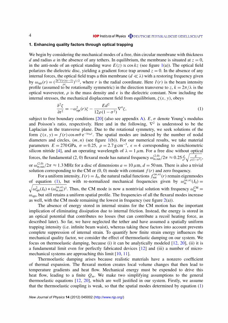
Figure 1. Illustration of a tethered membrane and its mode shapes. (a) Sideview of a membrane supported by a single tether inside a Fabry–Perot cavity.The membrane has radius a and thickness d, while the tether has length L anda square cross-section of width b. It is trapped in the anti-node of a standingoptical field with transverse intensity profile I (r) at the membrane location.(b) Displacement fields of a few selected membrane modes (in arbitrary units)for zero trapping intensity. The black outline indicates the equilibrium position.(m, n) denote the number of nodal diameters and circles, respectively. Thesystem dimensions are given by a = 10 µm, b = d = 50 nm and L = 50 µm.
enable quantum opto-mechanics in room-temperature environments [17, 18]. Compared to thenanosphere, our approach has two significant advantages. Firstly, the nanosphere scatters lightomni-directionally, leading to motional heating via photon recoil. Suppression of recoil heatingto reach the quantum regime requires spheres with sub-wavelength volumes, V/λ3
� 1 [17].In contrast, the planar membrane primarily couples the counter-propagating components ofthe trapping beam, strongly reducing recoil heating even for large systems. Secondly, thesemembranes can be fabricated using well-established techniques that have already yieldedexcellent mechanical and optical properties in a number of experiments [4, 19]. Our proposalthus shows how the ideas of optical levitation can be brought to bear upon ‘conventional’ andpractically deployable mechanical systems to yield remarkable coherence times.
This paper is organized as follows. In section 1, we develop a model for the optical forcesacting on thin membranes trapped in free space, and identify the ratio of optical energy to strainenergy (Uopt/Umech) as a relevant figure of merit for enhancing Q–frequency products. We thenapply these results to one particular form of dissipation, thermoelastic damping. Under realisticconditions, we show that Q–frequency product enhancements of three orders of magnitude arepossible, limited by practical dimensions of the system and trapping beam. In section 2, wemodify our analysis to account for trapping in a Fabry–Perot cavity. In particular, the diffractionof the optical field around the membrane causes a distortion of the cavity mode, and the opticalforces must be calculated self-consistently. Scattering of the field also gives rise to photon recoilheating, an additional source of decoherence of the mechanical motion. We find that tapering orapodizing the edges of the membrane can significantly reduce photon scattering and is crucialfor achieving long quantum coherence times. In section 3, the advantages of our scheme overother optical spring or trapping proposals are discussed. We conclude the paper in section 4.
New Journal of Physics 14 (2012) 045002 (http://www.njp.org/)
4
1. Enhancing quality factors through optical trapping
We begin by considering the mechanical modes of a free, thin circular membrane with thicknessd and radius a in the absence of any tethers. In equilibrium, the membrane is situated at z = 0,in the anti-node of an optical standing wave E(z) ∝ cos kz (see figure 1(a)). The optical fieldpolarizes the dielectric disc, yielding a gradient force trap around z = 0. In the absence of anyinternal forces, the optical field traps a thin membrane (d � λ) with a restoring frequency givenby ωopt(r) = (2k2 I (r)(ε−1)
ρc )1/2, where r is the radial coordinate. Here I (r) is the beam intensityprofile (assumed to be rotationally symmetric) in the direction transverse to z, k = 2π/λ is theoptical wavevector, ρ is the mass density and ε is the dielectric constant. Now including theinternal stresses, the mechanical displacement field from equilibrium, ζ(x, y), obeys
∂2ζ
∂t2= −ω2
opt(r)ζ −Ed2
12ρ(1 − σ 2)∇
4ζ, (1)
subject to free boundary conditions [20] (also see appendix A). E, σ denote Young’s modulusand Poisson’s ratio, respectively. Here and in the following, ∇
2 is understood to be theLaplacian in the transverse plane. Due to the rotational symmetry, we seek solutions of theform ζ(x, y) = f (r) cos mθ e−iωmt . The spatial modes are indexed by the number of nodaldiameters and circles, (m, n) (see figure 1(b)). For our numerical results, we take materialparameters E = 270 GPa, σ = 0.25, ρ = 2.7 g cm−3, ε = 4 corresponding to stoichiometricsilicon nitride [4], and an operating wavelength of λ = 1 µm. For a free disc without optical
forces, the fundamental (2, 0) flexural mode has natural frequency ω(2,0)m,nat/2π ≈ 0.25 d
a2
√E
ρ(1−σ 2),
or ω(2,0)m,nat/2π ≈ 1.3 MHz for a disc of dimensions a = 10 µm, d = 50 nm. There is also a trivial
solution corresponding to the CM or (0, 0) mode with constant f (r) and zero frequency.For a uniform intensity, I (r) = I0, the natural radial functions f (m,n)
nat (r) remain eigenmodesof equation (1), but with re-normalized mechanical frequencies given by ω(m,n)
m (I0) =√ω2
opt(I0) + (ω(m,n)m,nat)
2. Thus, the CM mode is now a nontrivial solution with frequency ωCMm =
ωopt, but still retains a uniform spatial profile. The frequencies of all the flexural modes increaseas well, with the CM mode remaining the lowest in frequency (see figure 2(a)).
The absence of energy stored in internal strains for the CM motion has the importantimplication of eliminating dissipation due to internal friction. Instead, the energy is stored inan optical potential that contributes no losses (but can contribute a recoil heating force, asdescribed later). So far, we have neglected the tether and have assumed a spatially uniformtrapping intensity (i.e. infinite beam waist), whereas taking these factors into account preventscomplete suppression of internal strain. To quantify how finite strain energy influences themechanical quality factor, we consider the effect of thermoelastic damping on our system. Wefocus on thermoelastic damping, because (i) it can be analytically modeled [12, 20], (ii) it isa fundamental limit even for perfectly fabricated devices [12] and (iii) a number of micro-mechanical systems are approaching this limit [10, 11].
Thermoelastic damping arises because realistic materials have a nonzero coefficientof thermal expansion. The flexural motion creates local volume changes that then lead totemperature gradients and heat flow. Mechanical energy must be expended to drive thisheat flow, leading to a finite Qm. We make two simplifying assumptions to the generalthermoelastic equations [12, 20], which are well justified in our system. Firstly, we assumethat the thermoelastic coupling is weak, so that the spatial modes determined by equation (1)
New Journal of Physics 14 (2012) 045002 (http://www.njp.org/)
5
20 (W / m )I µ 2
0 (W / m )I µ
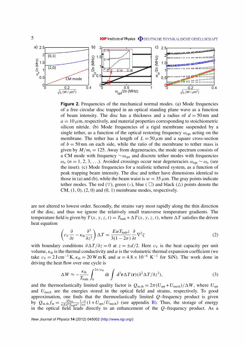
Figure 2. Frequencies of the mechanical normal modes. (a) Mode frequenciesof a free circular disc trapped in an optical standing plane wave as a functionof beam intensity. The disc has a thickness and a radius of d = 50 nm anda = 10 µm, respectively, and material properties corresponding to stoichiometricsilicon nitride. (b) Mode frequencies of a rigid membrane suspended by asingle tether, as a function of the optical restoring frequency ωopt acting on themembrane. The tether has a length of L = 50 µm and a square cross-sectionof b = 50 nm on each side, while the ratio of the membrane to tether mass isgiven by M/m t = 125. Away from degeneracies, the mode spectrum consists ofa CM mode with frequency ∼ωopt and discrete tether modes with frequenciesωn (n = 1, 2, 3, . . .). Avoided crossings occur near degeneracies ωopt ∼ ωn (seethe inset). (c) Mode frequencies for a realistic tethered system, as a function ofpeak trapping beam intensity. The disc and tether have dimensions identical tothose in (a) and (b), while the beam waist is w = 35 µm. The gray points indicatetether modes. The red (O), green (◦), blue ( �) and black (4) points denote theCM, (1, 0), (2, 0) and (0, 1) membrane modes, respectively.
are not altered to lowest order. Secondly, the strains vary most rapidly along the thin directionof the disc, and thus we ignore the relatively small transverse temperature gradients. Thetemperature field is given by T (x, y, z, t) = Tbath + 1T (x, y, z, t), where 1T satisfies the drivenheat equation (
cV∂
∂t− κth
∂2
∂z2
)1T =
EαTbathz
3(1 − 2σ)
∂
∂t∇
2ζ (2)
with boundary conditions ∂1T/∂z = 0 at z = ±d/2. Here cV is the heat capacity per unitvolume, κth is the thermal conductivity and α is the volumetric thermal expansion coefficient (wetake cV = 2 J cm−3 K, κth = 20 W m K and α = 4.8 × 10⁻⁶ K−1 for SiN). The work done indriving the heat flow over one cycle is
1W ≈ −κth
Tbath
∫ 2π/ωm
0dt
∫d3r1T (r)(∂21T/∂z2), (3)
and the thermoelastically limited quality factor is Qm,th = 2π(Uopt + Umech)/1W , where Uopt
and Umech are the energies stored in the optical field and strains, respectively. To goodapproximation, one finds that the thermoelastically limited Q–frequency product is givenby Qm,th fm =
45κthπ Ed2Tbathα2
1−σ
1+σ(1 + Uopt/Umech) (see appendix B). Thus, the storage of energy
in the optical field leads directly to an enhancement of the Q–frequency product. As a
New Journal of Physics 14 (2012) 045002 (http://www.njp.org/)
6
a) b) c)
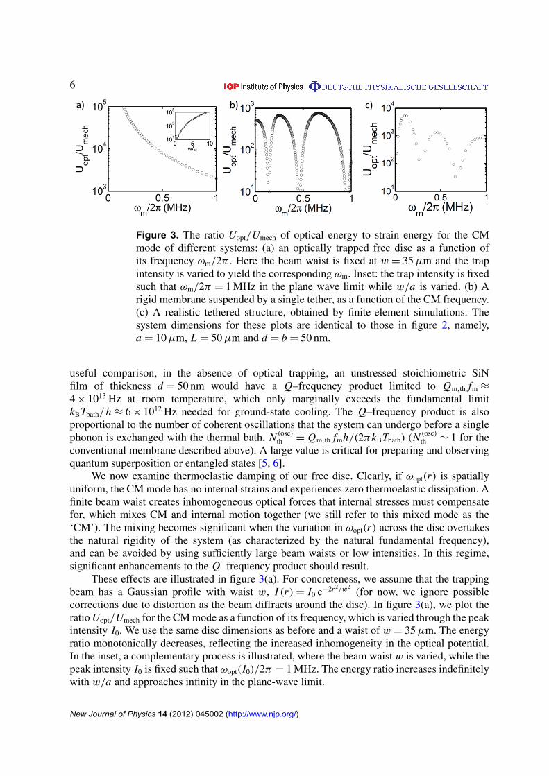
Figure 3. The ratio Uopt/Umech of optical energy to strain energy for the CMmode of different systems: (a) an optically trapped free disc as a function ofits frequency ωm/2π . Here the beam waist is fixed at w = 35 µm and the trapintensity is varied to yield the corresponding ωm. Inset: the trap intensity is fixedsuch that ωm/2π = 1 MHz in the plane wave limit while w/a is varied. (b) Arigid membrane suspended by a single tether, as a function of the CM frequency.(c) A realistic tethered structure, obtained by finite-element simulations. Thesystem dimensions for these plots are identical to those in figure 2, namely,a = 10 µm, L = 50 µm and d = b = 50 nm.
useful comparison, in the absence of optical trapping, an unstressed stoichiometric SiNfilm of thickness d = 50 nm would have a Q–frequency product limited to Qm,th fm ≈
4 × 10¹³ Hz at room temperature, which only marginally exceeds the fundamental limitkBTbath/h ≈ 6 × 10¹² Hz needed for ground-state cooling. The Q–frequency product is alsoproportional to the number of coherent oscillations that the system can undergo before a singlephonon is exchanged with the thermal bath, N (osc)
th = Qm,th fmh/(2πkBTbath) (N (osc)th ∼ 1 for the
conventional membrane described above). A large value is critical for preparing and observingquantum superposition or entangled states [5, 6].
We now examine thermoelastic damping of our free disc. Clearly, if ωopt(r) is spatiallyuniform, the CM mode has no internal strains and experiences zero thermoelastic dissipation. Afinite beam waist creates inhomogeneous optical forces that internal stresses must compensatefor, which mixes CM and internal motion together (we still refer to this mixed mode as the‘CM’). The mixing becomes significant when the variation in ωopt(r) across the disc overtakesthe natural rigidity of the system (as characterized by the natural fundamental frequency),and can be avoided by using sufficiently large beam waists or low intensities. In this regime,significant enhancements to the Q–frequency product should result.
These effects are illustrated in figure 3(a). For concreteness, we assume that the trappingbeam has a Gaussian profile with waist w, I (r) = I0 e−2r2/w2
(for now, we ignore possiblecorrections due to distortion as the beam diffracts around the disc). In figure 3(a), we plot theratio Uopt/Umech for the CM mode as a function of its frequency, which is varied through the peakintensity I0. We use the same disc dimensions as before and a waist of w = 35 µm. The energyratio monotonically decreases, reflecting the increased inhomogeneity in the optical potential.In the inset, a complementary process is illustrated, where the beam waist w is varied, while thepeak intensity I0 is fixed such that ωopt(I0)/2π = 1 MHz. The energy ratio increases indefinitelywith w/a and approaches infinity in the plane-wave limit.
New Journal of Physics 14 (2012) 045002 (http://www.njp.org/)

7
We now consider the realistic pendulum geometry shown in figure 1(a), where the tetherprovides an extremely weak restoring force for the ‘CM’ motion of the disc. We first presenta simplified analysis that isolates the role of the tether in the mode spectrum and Q–frequencyproduct. Specifically, we treat the membrane as a perfectly rigid point particle of mass M , whichexperiences an optical restoring force with frequency ωopt, while internal stresses alone act onthe tether. Then, for a tether of length L whose long axis is situated along x , the displacementfield φ(x, t) (where 06 x 6 L) satisfies the beam equation [20]
∂2φ
∂t2= −
Eb2
12ρ
∂4φ
∂x4. (4)
Here b denotes the width of the tether (assumed to be square in cross-section). The beam isclamped at x = 0, φ(0, t) = ∂xφ(0, t) = 0, while at x = L the boundary conditions are givenby ∂2
x φ(L , t) = 0 and M∂2t φ(L , t) = −Mω2
optφ(L , t) + Eb4∂3x φ(L , t)/12. The last equation
describes the acceleration of the membrane due to optical restoring forces and the shear forceimparted by the tether.
It is straightforward to solve for the system eigenmodes and the results are summarizedhere. For large mass ratios between the membrane and tether, M/m t → ∞, the modes usually
consist of a CM mode for the membrane with frequency ωCMm ≈
√ω2
p + ω2opt and a set of
discrete tether modes with frequencies ωn ≈ ((n+1/4)π
βL )2, where β = (12ρ/Eb2)1/4. The CMmode spectrum is understood as a low-frequency ‘pendulum’ mode (with natural frequencyωp ≈
√Eb4/4M L3, where ωp � ωopt, ωn for our systems of interest) whose frequency can
be strongly re-normalized by the optical force, while the tether mode spectrum results fromthe heavy membrane essentially acting as a second clamp. This description holds except neardegeneracies ωopt ≈ ωn, where coupling between the tether and membrane motions yieldsan avoided crossing whose width decreases with increasing mass ratio M/m t. This result isillustrated in figure 2(b), for a mass ratio of M/m t = 125 (corresponding to the disc sizeconsidered earlier attached to a tether of length L = 50 µm and width b = 50 nm). In figure 3(b),we plot the energy ratios Uopt/Umech for the CM motion as a function of ωopt. Here, the strainenergy is completely attributable to the tether, as we take the membrane to be a rigid object.The energy ratio is dramatically reduced near the avoided crossings, while away from thesecrossings, the energy ratio plateaus to a value near Uopt/Umech ∼ 8M/m t.
For a realistic tethered system (as in figure 1(a)) where the membrane is not perfectlyrigid, mode mixing between the tether and membrane and mixing between the CM and internalmembrane motion will occur simultaneously. We have numerically solved the full stress–strainequations for such a system using COMSOL, a commercial finite-element simulation package.A characteristic mode spectrum is plotted in figure 2(c) as a function of the peak trappingintensity I0, for parameters a = 10 µm, L = 50 µm, d = b = 50 nm and w = 35 µm. Away fromavoided crossings, the modes can clearly be characterized as tether modes (gray points) ormembrane modes (color). For our particular choice of beam waist size, the tethers themselvesexperience optical restoring forces, leading to a slight optical stiffening of tether modes thathave displacements along the optical propagation axis. Comparing the membrane modes, theCM mode lies lower in frequency than the flexural modes, as in the case of a free disc. A nearlydegenerate torsional (1, 0) mode also exists, which in principle should have no opto-mechanicalcoupling to the cavity field and can be ignored.
In figure 3(c), we plot the energy ratio Uopt/Umech for the CM mode of our tethered structureas a function of its frequency. The features displayed here are clearly a combination of those
New Journal of Physics 14 (2012) 045002 (http://www.njp.org/)

8
appearing in the limiting cases of a free disc and a rigid disc attached to a tether. In particular,large plateaus in Uopt/Umech appear away from avoided crossings with tether modes. The plateauheights can be higher than the limit Uopt/Umech ∼ 8M/m t predicted by the simple model, sincethe tether experiences an optical spring force as well. The decrease in the plateau heightswith increasing CM frequency is associated with increased mixing between pure CM andinternal membrane motion. For the realistic geometry considered here, an enhancement in theQ–frequency product of the order of ∼103 compared to a conventional system can be realizedat a frequency of ωm/2π ∼ 1 MHz. For a thermoelastically limited system, this corresponds toa coherence time of N (osc)
th ∼ 103.Although we have focused on thermoelastic processes, which can be exactly modeled, we
emphasize that our conclusions are qualitatively correct for any internal dissipative process. Forexample, a number of other mechanical systems phenomenologically suffer from frequency-independent dissipation, which may be due to effects such as tunneling in amorphous solids [13]or surface mechanisms [21]. Such systems can be characterized by a complex, frequency-independent Young’s modulus E = Er + iEi , where the imaginary component accounts fordissipation of strain energy. In this case, the quality factor in the presence of optical trappingbehaves like Qm,E = (Er/Ei)(1 + Uopt/Umech), again indicating the importance of storing energyin the lossless optical potential.
2. A membrane in a cavity: modification of modes and recoil heating
So far, we have assumed that the trapping beam has a Gaussian profile. For cavity opto-mechanics [1], it will be necessary to trap the membrane within a Fabry–Perot cavity, asillustrated in figure 1(a). For example, here, a relatively strong beam could be used for trapping,while a second, weaker beam with a nonzero intensity gradient at the trap position wouldfacilitate cooling of the CM motion or quantum state transfer processes [17, 18]. The membranescatters and diffracts the cavity light, which introduces two important effects. Firstly, the modewill no longer be Gaussian, and the new optical mode accommodated by the cavity mirrorsand the corresponding optical forces must be determined. Secondly, photon scattering out ofthe cavity reduces cavity finesse, and the associated random momentum kicks (‘photon recoil’)imparted on the membrane lead to additional decoherence.
To quantify these effects, we begin by calculating the cavity modes in the presence of themembrane using a modified Fox–Li propagation technique [22]. Here, the electric field is treatedwithin the scalar paraxial approximation, and thus it is completely described by its transverseprofile E(x, y). This approximation is justified by noting that the disc should primarily diffractlight at small angles θ . (ka)−1 around the z-axis, where k = 2π/λ is the optical wavevector.Within this approximation, free propagation over a distance z is accounted for by a phase shiftin the Fourier transform of the field profile, E(kx , ky)→eikz−i(k2
x +k2y)z/(2k) E(kx , ky). In our case,
we are interested in systems with rotational symmetry, and thus the transforms are implementedthrough the quasi-discrete Hankel transform described in [23]. Reflection off a circular mirrorwith radius of curvature Rc and reflectance Rm is characterized by the real-space transformation
E(x, y)→√
Rm E(x, y) exp(
2i k(Rc −√
R2c − (x2 + y2))
). Similarly, at the membrane location,
the wave front can undergo reflection and transmission. In the case of an infinite dielectricmembrane of uniform thickness d , the Fresnel equations yielding the thickness-dependent
New Journal of Physics 14 (2012) 045002 (http://www.njp.org/)

9
reflection and transmission coefficients r(d), t (d) can be exactly solved. Following the Fox–Litechnique, for a finite-size membrane or a membrane of non-uniform thickness, we apply theseexpressions to approximate the scattering amplitude and phase shift locally. For example, a fieldE(x, y) incident on the membrane undergoes the transformation E(x, y) → t (d(x, y))E(x, y)
upon transmission. Note that an initial wave front incident on the membrane thus splits into twowave fronts (a reflected and a transmitted field), and we keep track of the multiple scatteredfields to all orders to calculate the field buildup or cavity eigenmodes. In contrast, the originaltechnique of [22] only accounts for transmission. Thus, our approach properly captures theeffects of the reflected amplitude and back-scattered angle. Furthermore, our modified techniquereveals specifically at what frequencies resonances should occur.
We now discuss the effect of the membrane on the cavity finesse. To speed up calculations(taking advantage of the rotational symmetry) and given the relatively small size of the tether,only the central disc is treated here. As realistic parameters, we consider a membrane placedsymmetrically in the center of an optical cavity of length L = 1.99 cm with spherical mirrorshaving radii of curvature Rc = 1 cm and perfect reflectivity (such that we can identify thecontribution κmem to the cavity linewidth due to scattering from the membrane). The transverseextent of the spherical mirror surfaces is rm = 0.95 mm, i.e. all portions of the beam front withx2 + y2 > r 2
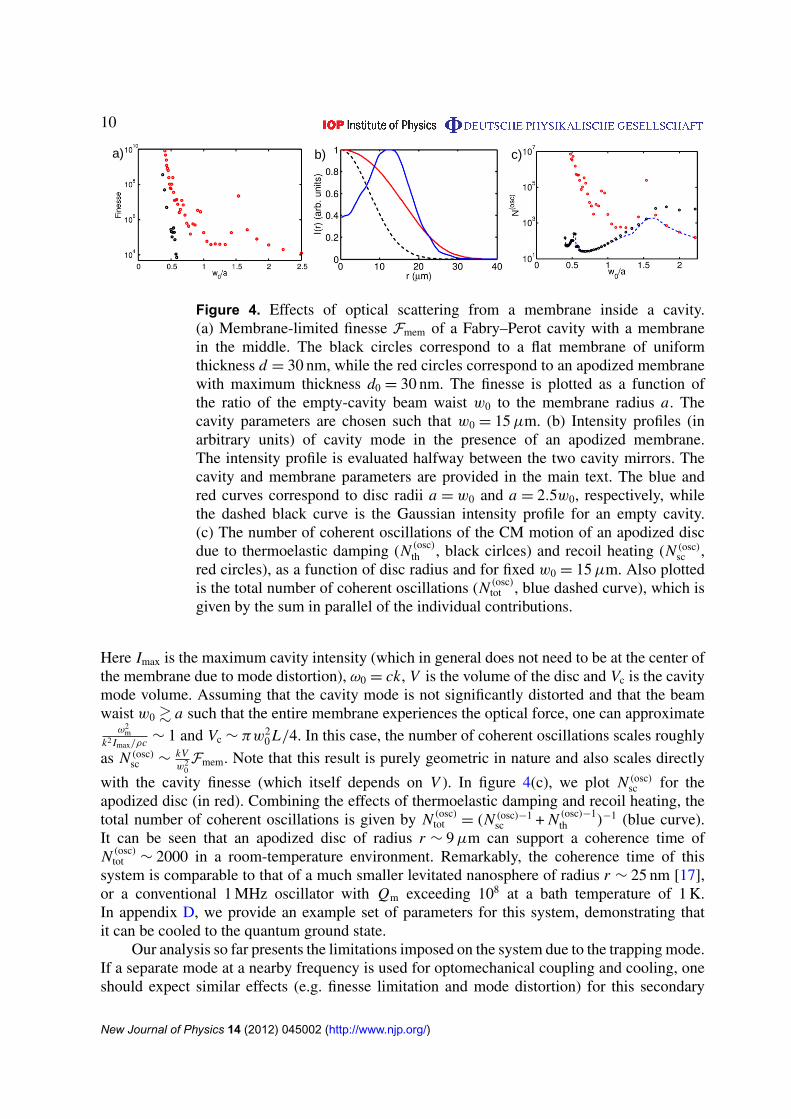
m are scattered out and set to zero upon reflection at the mirror. Accounting fora realistic mirror extent is important in determining the scattering rate, as a fully enclosingmirror would be a closed system and would exhibit no losses. An empty cavity in thisconfiguration yields a Gaussian mode of waist w0 ≈ 15 µm in the center. In figure 4(a), we plotthe membrane-limited cavity finesse Fmem ≡ πc/κmemL for a membrane of uniform thicknessd = 30 nm and varying radius a (black circles). Clearly, cavity losses are negligible whenthe nominal waist is small compared to the disc radius, w0/a . 1. In the regime w0/a & 1,however, the finesse rapidly drops, which is attributable to scattering by the hard edges ofthe disc. This effect is strongly reduced by ‘softening’ or apodizing the disc edge [24]. Infigure 4(a) (red circles), we also plot the finesse for a membrane whose thickness d(r) =
d0(1 − (r/a)2)2 tapers down to zero at the edge, where d0 = 30 nm is the maximum thickness.Remarkably, the apodization can improve the cavity finesse by several orders of magnitude.The modification of the cavity modes by the membrane is illustrated in figure 4(b), wherewe plot the transverse profile at the membrane position for some representative apodized discsizes.
We find the CM eigenmodes of the apodized disc using equation (A.3), which is ageneralization of equation (1) to a disc of non-uniform thickness. The optical potential ωopt(r) isnow evaluated using the modified cavity mode profiles. The thermoelastic limit is subsequentlycalculated using equations (2) and (3). In figure 4(c), the number of oscillations N (osc)
th due tothermoelastic damping is plotted (in black). Here the circulating intra-cavity power is chosensuch that the CM frequency is fixed at ωm/2π = 0.5 MHz.
We next consider the effect of photon recoil heating. We assume that each scattered photoncontributes the maximum possible momentum kick of hk along the z-axis, giving rise to amomentum diffusion process d〈p2
z 〉/dt = (hk)2 Rsc [17], where Rsc is the photon scatteringrate. Converting this expression into a jump rate, it can be shown that the number of coherentoscillations before a jump in the phonon number can be written as
N (osc)sc =
1
2π
V
Vc
ω0
κ
ω2m
k2 Imax/ρc. (5)
New Journal of Physics 14 (2012) 045002 (http://www.njp.org/)
10
Figure 4. Effects of optical scattering from a membrane inside a cavity.(a) Membrane-limited finesse Fmem of a Fabry–Perot cavity with a membranein the middle. The black circles correspond to a flat membrane of uniformthickness d = 30 nm, while the red circles correspond to an apodized membranewith maximum thickness d0 = 30 nm. The finesse is plotted as a function ofthe ratio of the empty-cavity beam waist w0 to the membrane radius a. Thecavity parameters are chosen such that w0 = 15 µm. (b) Intensity profiles (inarbitrary units) of cavity mode in the presence of an apodized membrane.The intensity profile is evaluated halfway between the two cavity mirrors. Thecavity and membrane parameters are provided in the main text. The blue andred curves correspond to disc radii a = w0 and a = 2.5w0, respectively, whilethe dashed black curve is the Gaussian intensity profile for an empty cavity.(c) The number of coherent oscillations of the CM motion of an apodized discdue to thermoelastic damping (N (osc)
th , black cirlces) and recoil heating (N (osc)sc ,
red circles), as a function of disc radius and for fixed w0 = 15 µm. Also plottedis the total number of coherent oscillations (N (osc)
tot , blue dashed curve), which isgiven by the sum in parallel of the individual contributions.
Here Imax is the maximum cavity intensity (which in general does not need to be at the center ofthe membrane due to mode distortion), ω0 = ck, V is the volume of the disc and Vc is the cavitymode volume. Assuming that the cavity mode is not significantly distorted and that the beamwaist w0 & a such that the entire membrane experiences the optical force, one can approximate
ω2m
k2 Imax/ρc ∼ 1 and Vc ∼ πw20 L/4. In this case, the number of coherent oscillations scales roughly
as N (osc)sc ∼
kVw2
0Fmem. Note that this result is purely geometric in nature and also scales directly
with the cavity finesse (which itself depends on V ). In figure 4(c), we plot N (osc)sc for the
apodized disc (in red). Combining the effects of thermoelastic damping and recoil heating, thetotal number of coherent oscillations is given by N (osc)
tot = (N (osc)−1sc + N (osc)−1
th )−1 (blue curve).It can be seen that an apodized disc of radius r ∼ 9 µm can support a coherence time ofN (osc)
tot ∼ 2000 in a room-temperature environment. Remarkably, the coherence time of thissystem is comparable to that of a much smaller levitated nanosphere of radius r ∼ 25 nm [17],or a conventional 1 MHz oscillator with Qm exceeding 108 at a bath temperature of 1 K.In appendix D, we provide an example set of parameters for this system, demonstrating thatit can be cooled to the quantum ground state.
Our analysis so far presents the limitations imposed on the system due to the trapping mode.If a separate mode at a nearby frequency is used for optomechanical coupling and cooling, oneshould expect similar effects (e.g. finesse limitation and mode distortion) for this secondary
New Journal of Physics 14 (2012) 045002 (http://www.njp.org/)
11
mode as well. We note, however, that it should also be possible to separately optimize theparameters such as finesse, beam waist and effective cavity length for the two modes by usingsignificantly different wavelengths or compound cavity geometries.
3. Comparison of optical trapping schemes
We emphasize that our approach to reach the quantum regime, which relies upon achievingultrahigh-Q factors, is fundamentally different from other ‘optical spring’ proposals based onoptical backaction forces [25, 26]. In the latter case, the linear coupling of the mechanicaldisplacement to the intra-cavity intensity can yield a dynamic optical spring effect. This effect,however, is accompanied by significant Raman scattering of the optical pump field, whichcauses phonons to be rapidly removed and added to the system. While this does not precludeground state cooling [26], our analysis below demonstrates that it imposes severe limitationson the quantum coherence time and makes it difficult to prepare, e.g., quantum superpositionstates. In contrast, in our scheme, the phonons are truly long-lived excitations.
Specifically, we consider the dynamic optical spring resulting from a mechanical degreeof freedom whose displacement is linearly coupled to the optical cavity frequency. Thecorresponding Hamiltonian for such a system in a rotating frame is [27]
Hint =p2
2m+
1
2mω2
m z2− hδa†a − hω′ za†a − h�L(a + a†). (6)
Here a is the annihilation operator for the optical mode, z, p are the position and momentumoperators corresponding to the mechanical resonator, ωm is the natural mechanical frequency,δ = ωL − ω0 is the frequency detuning between an external pump field driving the optical cavityand the optical resonance frequency ω0 (when the mechanical resonator is in equilibrium),�L is the driving amplitude and ω′ is the optical cavity frequency shift per unit mechanicaldisplacement. In addition to the Hamiltonian terms, the optical cavity is assumed to have lossescharacterized by a linewidth κ .
For weak opto-mechanical coupling, it is customary to linearize the optical cavity dynamicsaround the classical steady-state value 〈a〉 = α = i �L/(κ/2 − i δ) (here we have incorporated asteady-state shift of the optical resonance frequency into our definition of the detuning δ), andeliminate the cavity to yield an effective susceptibility χ(ω) of the mechanical displacement inresponse to an external force f (ω) [27]. Specifically, one finds that
χ(ω)−1= ω2
m − ω2 +16ωmδ�2
m
4δ2 + (κ − 2iω)2. (7)
Here we have defined an effective opto-mechanical driving amplitude �m = gα, and g =
ω′zzp = ω′
√h
2mωmis the optical cavity frequency shift per unit mechanical zero-point uncertainty.
In the perturbative limit, this expression can be written in terms of the susceptibility of a simpleoscillator with an effective linewidth and frequency that is modified due to opto-mechanicalinteractions, χ(ω)−1
≈ ω2m,eff − ω2
− i ω0eff. The effective linewidth and mechanical frequencyshift can be interpreted as resulting from optically induced cooling (or heating) and a dynamicoptical spring constant, respectively. In the relevant regime of large detuning δ � ω, κ , andwhen the optical spring is dominant compared to the natural mechanical frequency, the effective
New Journal of Physics 14 (2012) 045002 (http://www.njp.org/)

12
mechanical frequency is given by [27, 28]
ωm,eff ≈ 2�m
√ωm
δ. (8)
The damping rate is given by
0eff ≈ �2mκ
ωm
ωm,eff
[1
(κ/2)2 + (δ + ωm,eff)2−
1
(κ/2)2 + (δ − ωm,eff)2
], (9)
which is interpreted as the difference between anti-Stokes and Stokes scattering rates. Note thatfor positive detuning δ > 0, the opto-mechanical interaction yields an increase in the mechanicalfrequency but an anti-damping force (0eff < 0). One can achieve simultaneous stiffening andcooling by employing multiple beams with different amplitudes and detunings [26], but for ourpurposes it is sufficient to consider only the beam that leads to stiffening.
We wish to consider the ratio of the effective mechanical frequency to the rate ofdecoherence 0d induced by optical Raman scattering, which is given by the sum (and notdifference) of the anti-Stokes and Stokes scattering rates. This is an important point—althoughthe removal and addition of a phonon by two Raman scattering events has no net effect interms of energy, it does destroy quantum coherence. In the relevant limit of large detuning anddominant optical spring effect, one finds that
ωm,eff
0d≈
2δ
κ. (10)
This result states that the cavity must be driven very far off resonance in order to yield afrequency shift that is much larger than the decoherence rate. Operating at large detuningin turn requires extremely large cavity input powers to get an appreciable optical springeffect. As an example, we consider the dynamic spring constant for a realistic geometry,such as a Fabry–Perot cavity of length L = 1 cm and cavity finesse F = 105 (with the cavitylinewidth given by κ = πc/(FL) = 2π×150 kHz for our specific parameters). The opticaldriving amplitude is related to the input power Pi through �L =
√κ Pi/(2hωL) for perfect in-
coupling efficiency, while the opto-mechanical interaction strength is of order ω′∼ ω0/L . The
operating wavelength is taken to be λ = 1 µm. We also assume that the SiN membrane has aradius a = 10 µm and that it undergoes pure CM motion (such that its effective motional massis the same as the physical mass). Then, an input power of Pi ∼ 2 kW is required if one wants toachieve the number of coherent oscillations of N (osc)
=ωm,eff
2π0d∼103 and an effective mechanical
frequency of ωm,eff ∼ 2π×1 MHz. This corresponds to an input intensity of ∼10 W µm−2 for abeam focused to a size comparable to the membrane radius.
In contrast, in our static trapping scheme, a comparable mechanical frequency andcoherence time can be achieved for an intra-cavity intensity of ∼0.1 W µm−2, and the cavity canbe driven resonantly to facilitate the intra-cavity field buildup. Because the static trap results inthe membrane being trapped at an anti-node, there is no linear opto-mechanical coupling for thetrapping field and the lowest-order opto-mechanical coupling is quadratic in nature. The anti-Stokes and Stokes scattering rates in this case (at frequencies ωL ± 2ωm) have been calculatedin [29] and are extremely rare for our realistic systems (occurring at a sub-Hz level), leading tonegligible decoherence.
Furthermore, regardless of the trapping scheme used, our analysis properly captures therole that strong, spatially non-uniform optical forces have in mixing internal motion, which isneglected in lowest-order opto-mechanical models but is relevant to most flexural systems. In
New Journal of Physics 14 (2012) 045002 (http://www.njp.org/)

13
the case of the dynamic optical spring, for example, our model shows that the opto-mechanicalcoupling strength g decreases significantly at the large intensities needed to observe strongoptical spring effects (see appendix C).
We also point out the proposal in [30] that is qualitatively similar to ours, which involves theoptical levitation of a macroscopic mirror using dipole forces. We believe that their conclusionof the feasibility of levitating such a macroscopic system is based on a number of erroneousassumptions. Specifically, their expression for the trapping force is derived from the opticalpolarizability of a sub-wavelength particle. In this regime, both the trapping force and massincrease linearly with the volume of the particle, and thus the CM oscillation frequency remainssize independent for a fixed intensity. However, for objects greater than a wavelength, theratio of trapping force to mass decreases (inversely with thickness, for the case of a planarstructure [31]), and thus the authors of [30] greatly underestimate the power requirements fortrapping a macroscopic mirror. In contrast, our membranes remain thin along the trapping axis,which allows for sub-wavelength formulae to hold. Furthermore, their calculation of the recoilheating rate only accounts for scattering from thermal density fluctuations (this mechanismis important for guided modes in a low-loss fiber) [32]. However, this ignores the largescattering cross-section of the externally illuminated dielectric object. Indeed, it has been shownpreviously that wavelength-scale particles already suffer severe decoherence times (N (osc)
sc ∼ 1)due to this effect [17]. This mechanism is suppressed in our scheme because of our planargeometry and the use of a cavity mode to trap, which enables the cavity mirrors to re-capturemuch of the scattered light.
4. Conclusion and outlook
We have described a technique that allows the ideas of optical levitation to be appliedto conventional, scalable mechanical systems, yielding Q–frequency products significantlyhigher than what material properties would nominally dictate. Although we have focused onthermoelastic losses in the above calculations, we expect similar improvements for any otherinternal damping mechanism. The key idea is that it is possible to circumvent natural materiallimits of damping by storing energy in a lossless optical field rather than the internal strain. Bymaking the ratio of these energies large, Uopt/Umech � 1, any internal losses can be suppressedby a corresponding degree. This fundamental observation allows one to design a novel classof mechanical systems that can be fabricated and deployed using conventional techniques, yetyield Q–frequency products that are several orders of magnitude higher than previous systems.We believe that this work will stimulate further investigation into the relationship betweenoptical forces and material dissipation in a number of systems where the mechanical motioncan be strongly renormalized by light [26, 33]. Furthermore, we anticipate that such studieswill open up interesting possibilities for quantum manipulation of mechanical systems in room-temperature environments.
Acknowledgments
The authors thank Dal Wilson and Richard Norte for many helpful discussions. DECacknowledges support from the NSF (grant no. PHY-0803371), the Gordon and Betty MooreFoundation through Caltech’s Center for the Physics of Information (CPI), and FundacioPrivada Cellex Barcelona. KN acknowledges support from the CPI. HJK and OJP acknowledge
New Journal of Physics 14 (2012) 045002 (http://www.njp.org/)

14
support from the DARPA ORCHID program. HJK also acknowledges support from the NSFand DoD National Security Science and Engineering Faculty Fellowships (NSSEFF) program.
Appendix A. Derivation of the membrane equation
Here we derive the equation of motion for a thin non-uniform disc of thickness d(r), which has areflection symmetry around z = 0 (such that the surface of the plate is located at z = ±d(r)/2).We are interested in the situation where the thickness is much less than the characteristictransverse size (e.g. the radius a of a circular disc), such that its degree of freedom along thethin direction can be effectively eliminated and the flexural motion can be described by a two-dimensional displacement field ζ(x, y). The equation of motion for ζ(x, y) can be obtainedby a generalization of the derivation for a uniform disc given in [20]. Specifically, the energyassociated with the displacement field ζ(x, y) is given by
Umech =E
24(1 − σ 2)
∫dx dy d(x, y)3
[(ζxx + ζyy
)2+ 2(1 − σ)
((ζxy)
2− ζxxζyy
)]. (A.1)
Here E, σ are the Young’s modulus and Poisson’s ratio, respectively, while ζxx =∂2ζ
∂x2 , etc. Toderive the equilibrium field ζ(x, y) under some external normal pressure P(x, y), we employthe variational principle to minimize the system energy. Under small variations δζ and followingsome algebra, the variation in Umech can be written as the sum of an integral over the transversearea of the disc and two integrals over the circumference or edge of the disc,
δUmech =
∫dx dy Z1δζ +
∮dl Z2
∂δζ
∂n+
∮dl Z3δζ. (A.2)
Here Z i are complicated expressions involving ζ and d(r) whose forms are given below, while ndenotes the normal to the edge of the disc. The integral over the disc area yields the equilibriumequation of the disc, Z1 = P(x, y), or the dynamical equation can be obtained by replacingP(x, y)→ − ρd(r) ∂2ζ
∂t2 . Doing so, and including the effect of external optical forces, one findsthat
∂2ζ
∂t2= −ω2
opt(r)ζ −E
12ρ(1 − σ 2)d(r)
[∇
2(g(r)∇2ζ
)− (1 − σ)
(ζyygxx + ζxx gyy − 2ζxygxy
)].
(A.3)
Here we have defined g(r) = d(r)3, and ∇2 is understood to be the Laplacian in the transverse
plane. As described in the main text, ωopt(r) = ( 2k2 I (r)(ε−1)
ρc )1/2. For a disc with free boundaryconditions at the edge, the quantities δζ and ∂δζ/∂n are arbitrary on the boundary, so thecoefficients Z2,3 should vanish, yielding the two boundary conditions. Defining n and l to bethe normal and tangential directions to the edge of the disc, and θ as the local angle between xand n, these boundary conditions become
0 =∂
∂n
(g∇
2ζ)
+ (1 − σ)
[∂
∂l
(−gζxy cos 2θ + (g/2) sin 2θ(ζxx − ζyy)
)+ cos θ(ζyygx − ζxygy) + sin θ(ζxx gy − ζxygx)
], (A.4)
0 = ∇2ζ + (1 − σ)
(2ζxy sin θ cos θ − ζyy cos2 θ − ζxx sin2 θ
).
New Journal of Physics 14 (2012) 045002 (http://www.njp.org/)
15
Appendix B. Thermoelastic damping
Solving equation (2) and substituting into equation (3), one finds that
1W ≈πωmα2 E2d5Tbath
1080κth(1 − σ)2
∫dx dy (∇2ζ )2. (B.1)
Let us now compare this quantity with the total strain energy Umech given in equation (A.1).For simplicity, here we specialize to the case where the disc has a uniform thickness d, such that
Umech =Ed3
24(1 − σ 2)
∫dx dy
[(∇2ζ )2 + 2(1 − σ)
((ζxy)
2− ζxxζyy
)]. (B.2)
Note that 1W and Umech have similar forms, as both involve an integral over the membranearea of the quantity (∇2ζ )2. The strain energy contains a second term, however, whose relativeimportance we characterize now. The second term can in fact be re-written as a line integralaround the circumference of the membrane,∫
dx dy (ζxy)2− ζxxζyy =
∮dx ζxyζx −
∮dy ζyyζx . (B.3)
This boundary integral vanishes identically for certain types of shapes or boundaryconditions, such as a clamped membrane. For our free disc, this boundary term doesnot identically vanish, but numerically we can confirm that the boundary contribution issmall relative to the total strain energy. To a good approximation then we can writeUmech ≈
Ed3
24(1−σ 2)
∫dx dy (∇2ζ )2. This leads to the expression for the thermoelastically limited
Q–frequency product given in the main text,
Qm,th fm =45κth
π Ed2Tbathα2
1 − σ
1 + σ
(1 +
Uopt
Umech
). (B.4)
Appendix C. Modification of opto-mechanical coupling strengths
Our theory of optical trapping of membranes predicts dramatic corrections to the simple modelof opto-mechanical interactions given by equation (6), when the optical restoring forces (eitherstatic or dynamic) become large compared to the natural ridigity of the membrane. In thisscenario of strong optical forces, the mechanical mode shape and thus the opto-mechanicalcoupling strength g become functions of intensity as well, with g generally decreasing withlarger intensity. The origin of this effect is intuitively seen by considering a membrane thatinteracts with a Gaussian cavity mode whose beam waist w is smaller than the membrane radiusa. Then, if the optical restoring forces are large compared to the membrane stiffness, the opticalbeam in fact resembles a new boundary condition that ‘pins’ the region r . w of the membraneinto place. This reduces the overlap between the mechanical displacement field and the opticalbeam, and thus g.
This effect is illustrated in figure C.1 for a free SiN membrane of thickness d = 30 nm anda = 25 µm, interacting with a beam of waist w = 15 µm. In this calculation the membraneis statically trapped, although a similar effect would occur for sufficiently large dynamicalbackaction forces as well. In figure C.1(a), we calculate the opto-mechanical coupling strengthg (to another cavity mode that has the same beam waist but exhibits an intensity gradient at the
New Journal of Physics 14 (2012) 045002 (http://www.njp.org/)

16
a) b)
Figure C.1. Effect of large intensity on opto-mechanical coupling strength.(a) Opto-mechanical coupling strength g of a trapped free disc as a function ofCM frequency. The coupling strength is normalized by the value correspondingto rigid (pure CM) motion g0. A decrease in g for increasing frequency iscaused by the non-uniform optical force pinning the center of the disc in place.The dimensions for this simulation are d = 30 nm, a = 25 µm and w = 15 µm.(b) Displacement field ζ(x, y) (in arbitrary units) for a free disc of the samedimensions, for a trap frequency of ωm/2π = 300 kHz. The displacement fieldclearly illustrates the pinning effect created by the optical forces.
membrane position) as a function of the CM frequency, which is varied through the intensity ofthe trapping beam. The value of g is calculated using the expression [4]
g ∝ zzp
∫dx dy e−2(x2+y2)/w2
ζ(x, y)/max|ζ |. (C.1)
In figure C.1(a), we have normalized the obtained value of g with the value g0 if the motion werepurely CM, where the displacement field ζ is constant. At larger frequencies, g dramaticallydecreases, reflecting the ‘pinning’ effect that the optical force has on the center of the membrane.This is also directly seen in figure C.1(b), where we plot the displacement field ζ(x, y) for a CMfrequency ωm/2π = 300 kHz.
Appendix D. Quantum opto-mechanics with a tethered membrane
In this section, we show that the membrane trapped inside a Fabry–Perot cavity analyzed insection 2 can be cooled to the ground state starting from room temperature under realisticconditions.
To recall, the apodized membrane with radius r = 9 µm is positioned inside a cavitywith nominal beam waist w0 ≈ 15 µm, and we assume that the CM motion is trappedwith a frequency of ωm/(2π) = 0.5 MHz (see table D.1 for a summary of parameters). Thecorresponding peak circulating intensity of the trapping field is Imax ≈ 0.04 W µm−2. Such aconfiguration yields a scattering-limited cavity finesse of Fmem ∼ 3 × 10⁵. For our followinganalysis, we take a more conservative value of F = 105 for the overall cavity finesse (e.g.the finesse is limited by the cavity mirror transmission). The corresponding cavity linewidthκ/(2π) = 75 kHz is much smaller than ωm, ensuring that the ‘sideband-resolved regime’ isreached and efficient optical cooling can take place [27].
New Journal of Physics 14 (2012) 045002 (http://www.njp.org/)
17
Table D.1. Example cooling parameters for optically trapped membrane.
Total cavity decay κ/2π ,Opto-mech. coupling Cavity membrane contribution
Cavity length Beam waist strength g/2π finesse F κmem/2π
1.99 cm 15 µm 40 Hz 105 75 and 25 kHz
Mech. frequency Intra-cavity intensities: Background Final phonon Finalωm/2π trapping, cooling beams gas pressure number 〈n f 〉 temperature Tf
0.5 MHz 4 × 10¹⁰ and 2 × 10⁶ W m−2∼10−10 torr 2.5 × 10⁻³ 4 µK
The membrane is trapped at an anti-node of the ‘primary’ mode used for trapping; however,as in [17, 18], a secondary optical cavity mode with a maximum intensity gradient at themembrane position can be used to facilitate linear opto-mechanical coupling and cooling.The theory of cooling in this configuration has been thoroughly analyzed in previouswork [17, 18, 34], and the results are briefly summarized here. We assume that the circulatingintensity in the secondary mode is a small fraction ξ � 1 compared to that in the primary mode,so that the trapping (cooling) effect of the secondary (primary) mode is negligible (we taken = 5 × 10⁻⁵ for our analysis). The optical cooling rate effected by the second mode is obtainedfrom equation (9), with a calculated opto-mechanical coupling strength of g/(2π) = 40 Hz forour particular geometry. We choose a detuning of δ ≈ −ωm for our secondary or cooling beam,which maximizes the cooling efficiency in the sideband-resolved regime.
Using these parameters, we find that optical cooling can yield a steady-state phononoccupation number and temperature of 〈n f 〉 = 2.5 × 10⁻³ and Tf = 4 µK, respectively, startingfrom room temperature. Thus, the ground state of the CM motion can be prepared withextremely high fidelity. So far in our analysis, we have assumed that re-heating of the CMmotion occurs due to thermoelastic processes and photon recoil. However, it is known thatdamping and re-thermalization due to collisions with background gas molecules can be amajor decoherence effect for levitated systems [17, 18]. In the low-pressure regime, where gasmolecules independently collide with the membrane, the energy damping rate for our systemcan be derived using the techniques of [35] and is given by γg = 96Pg/(πvρd0), where Pg is thegas pressure, v is the mean molecular speed, ρ is the mass density of the membrane and d0 is itsmaximum thickness. For our system, the effect of the background gas is negligible compared toother heating sources at pressure levels of Pg ∼ 10−10 torr.
References
[1] Cleland A 2009 Optomechanics: photons refrigerating phonons Nature Phys. 5 458–60[2] Teufel J D, Donner T, Li D, Harlow J W, Allman M S, Cicak K, Sirois A J, Whittaker J D, Lehnert K W and
Simmonds R W 2011 Sideband cooling of micromechanical motion to the quantum ground state Nature475 359–63
[3] Chan J, Alegre T P M, Safavi-Naeini A H, Hill J T, Krause A, Groblacher S, Aspelmeyer M and Painter O2011 Laser cooling of a nanomechanical oscillator into its quantum ground state Nature 478 89–92
[4] Wilson D J, Regal C A, Papp S B and Kimble H J 2009 Cavity optomechanics with stoichiometric SiN filmsPhys. Rev. Lett. 103 207204
New Journal of Physics 14 (2012) 045002 (http://www.njp.org/)
18
[5] Marshall W, Simon C, Penrose R and Bouwmeester D 2003 Towards quantum superpositions of a mirrorPhys. Rev. Lett. 91 130401
[6] Genes C, Mari A, Tombesi P and Vitali D 2008 Robust entanglement of a micromechanical resonator withoutput optical fields Phys. Rev. A 78 032316
[7] Chang D E, Safavi-Naeini A H, Hafezi M and Painter O 2011 Slowing and stopping light using anoptomechanical crystal array New J. Phys. 13 023003
[8] Geraci A A, Papp S B and Kitching J 2010 Short-range force detection using optically cooled levitatedmicrospheres Phys. Rev. Lett. 105 101101
[9] Li T, Kheifets S, Medellin D and Raizen M G 2010 Measurement of the instantaneous velocity of a Brownianparticle Science 328 1673–5
[10] Verbridge S S, Parpia J M, Reichenbach R B, Bellan L M and Craighead H G 2006 High quality factorresonance at room temperature with nanostrings under high tensile stress J. Appl. Phys. 99 124304
[11] Lee J E-Y and Seshia A A 2009 5.4 MHz single-crystal silicon wine glass mode disk resonator with qualityfactor of 2 million Sensors Actuators A 156 28–35
[12] Lifshitz R and Roukes M L 2000 Thermoelastic damping in micro- and nanomechanical systems Phys. Rev.B 61 5600–9
[13] Pohl R O, Liu X and Thompson E 2002 Low-temperature thermal conductivity and acoustic attenuation inamorphous solids Rev. Mod. Phys. 74 991–1013
[14] Ashkin A 2007 Optical Trapping and Manipulation of Neutral Particles Using Lasers: A Reprint Volume withCommentaries (Singapore: World Scientific)
[15] Ashkin A and Dziedzic J M 1976 Optical levitation in high vacuum Appl. Phys. Lett. 28 333–5[16] Libbrecht K G and Black E D 2004 Toward quantum-limited position measurements using optically levitated
microspheres Phys. Lett. A 321 99–102[17] Chang D E, Regal C A, Papp S B, Wilson D J, Ye J, Painter O, Kimble H J and Zoller P 2010 Cavity opto-
mechanics using an optically levitated nanosphere Proc. Natl Acad. Sci. USA 107 1005–10[18] Romero-Isart O, Juan M L, Quidant M L and Cirac J I 2010 Toward quantum superposition of living
organisms New J. Phys. 12 033015[19] Sankey J C, Yang C, Zwickl B M, Jayich A M and Harris J G E 2010 Strong and tunable nonlinear
optomechanical coupling in a low-loss system Nature Phys. 6 707–12[20] Landau L D and Lifshitz E M 1986 Theory of Elasticity 3rd edn (Boston, MA: Butterworth-Heinemann)[21] Penn S D, Ageev A, Busby D, Harry G M, Gretarsson A M, Numata K and Willems P 2006 Frequency and
surface dependence of the mechanical loss in fused silica Phys. Lett. A 352 3–6[22] Fox A G and Li T 1968 Computation of optical resonator modes by the method of resonance excitation IEEE
J. Quantum Electron. 4 460–5[23] Li Yu, Huang M, Chen M, Chen W, Huang W and Zhu Z 1998 Quasi-discrete Hankel transform Opt. Lett.
23 409–11[24] Born M, Wolf E and Bhatia A B 2000 Principles of Optics: Electromagnetic Theory of Propagation,
Interference and Diffraction of Light (Cambridge: Cambridge University Press)[25] Braginsky V B and Vyatchanin S P 2002 Low quantum noise tranquilizer for Fabry–Perot interferometer
Phys. Lett. A 293 228–34[26] Corbitt T, Chen Y, Innerhofer E, Muller-Ebhardt H, Ottaway D, Rehbein H, Sigg D, Whitcomb S, Wipf C and
Mavalvala N 2007 An all-optical trap for a gram-scale mirror Phys. Rev. Lett. 98 150802[27] Marquardt F, Chen J P, Clerk A A and Girvin S M 2007 Quantum theory of cavity-assisted sideband cooling
of mechanical motion Phys. Rev. Lett. 99 093902[28] Jayich A M, Sankey J C, Zwickl B M, Yang C, Thompson J D, Girvin S M, Clerk A A, Marquardt F and
Harris J G E 2008 Dispersive optomechanics: a membrane inside a cavity New J. Phys. 10 095008[29] Nunnenkamp A, Børkje K, Harris J G E and Girvin S M 2010 Cooling and squeezing via quadratic
optomechanical coupling Phys. Rev. A 82 021806[30] Singh S, Phelps G A, Goldbaum D S, Wright E M and Meystre P 2010 All-optical optomechanics: an optical
spring mirror Phys. Rev. Lett. 105 213602
New Journal of Physics 14 (2012) 045002 (http://www.njp.org/)

19
[31] Meystre P, Wright E M, McCullen J D and Vignes E 1985 Theory of radiation-pressure-driven interferometersJ. Opt. Soc. Am. B 2 1830–40
[32] Boyd R W 1992 Nonlinear Optics (New York: Academic)[33] Rosenberg J, Lin Q and Painter O 2009 Static and dynamic wavelength routing via the gradient optical force
Nature Photonics 3 478–83[34] Pender G A T, Barker P F, Marquardt F and Monteiro T S 2011 Optomechanical cooling of levitated spheres
with doubly-resonant fields, arXiv:1107.0686[35] Hutcherson S and Ye W 2004 On the squeeze-film damping of micro-resonators in the free-molecule regime
J. Micromech. Microeng. 14 1726–33
New Journal of Physics 14 (2012) 045002 (http://www.njp.org/)
Related Documents