(IJACSA) International Journal of Advanced Computer Science and Applications, Vol. 4, No. 12, 2013 Ultrafast Scalable Embedded DCT Image Coding for Tele-immersive Delay-Sensitive Collaboration Mauritz Panggabean, Maciej Wielgosz, Harald Øverby, and Leif Arne Rønningen Department of Telematics (ITEM) Norwegian University of Science and Technology (NTNU) N-7491, Trondheim, Norway Abstract—A delay-sensitive, real-time, tele-immersive collabo- ration for the future requires much lower end-to-end delay (EED) for good synchronization than that for existing teleconference systems. Hence, the maximum EED must be guaranteed, and the visual-quality degradation must be graceful. Distributed Multimedia Plays (DMP) architecture addresses the envisioned collaboration and the challenges. We propose a DCT-based, embedded, ultrafast, quality scalable image-compression scheme for the collaboration on the DMP architecture. A parallel FPGA implementation is also designed to show the technical feasibility. I. I NTRODUCTION Figure 1 shows a simple example of the envisioned collabo- ration. A and B engage each other in a real-time delay-sensitive communication. They are both a source and a receiver, whereas C only receives data from them. As EED is not critical for C, C can use video-streaming technologies over the Internet. The capacity in the multihop links between A, B and C varies because other users outside the collaboration also use them. Moreover, the target quality of experience (QoE) is so high that it closely approximates reality, i.e. near-natural. A B TB TA TT Domain X Domain Y Domain Z C Source and receiver Source and receiver Receiver Server A Server B Fig. 1: A simple example of the futuristic collaboration. The collaboration environment is an immersive collabora- tion space (CS) more advanced than the CAVE [5]. To achieve the near-natural QoE, each surface in the CS is tiled with autostereoscopic multiview 3D displays with arrays of high- end cameras, microphones, and speakers. At high frame rate, the video traffic from a CS is several orders of magnitude higher than that in typical videoconferencing. It is reduced by segmenting only the important objects in the video, such as the faces and bodies of the performers. A maximum EED for good synchronization between A and B must be guaranteed. Some studies show that the optimal EED for synchronizing rhythmic clapping hands from different places is 11.5ms [4]. Longer delays will produce increasingly severe tempo deceleration while shorter ones yield a modest yet surprising acceleration. Since musical instruments such as percussion are rhythmically very similar to clapping hands, percussion musicians who collaborate from remote places require the same EED for synchronization. It also applies to collaborative dancing because dancers perform based on visual cues from each other [40]. Other cases include collaborative singing and remote conducting [18]. An EED consists of delays due to propagation, transmis- sion, and signal processing. Propagation delay is caused by physical distances, and transmission delay depends on link capacity, queueing delay, and computations at the network nodes. The latter is the electronic bottleneck that limits the achievable capacity of a network [27]. Less capacity in the net- work causes congestion and increases queuing delay. Instead of multipath transmission, single path is assumed to simplify routing delay. Exploiting temporal redundancy when encoding video data gives better quality but increases encoding delay. Intraframe video encoding is, therefore, preferred as shown by a recent experiment that uses JPEG [10]. Since we pursue very low latency for encoding and decoding in the order of μs per frame, parallel computation must be used as much as possible. The Distributed Multimedia Plays (DMP) architecture has been proposed to facilitate the envisioned collaboration [17] with the idea that maximum EED is guaranteed if each network node guarantees that the local delay never exceeds its maximum value. This value and the propagation delay can be estimated prior to packet transmission. Because the routers and switches in DMP have advanced functionalities to guarantee Quality of Service (QoS), DMP belongs to the network-centric approach rather than the end-system-based approach [37]. The idea has three important implications. First, a DMP network node must be able to drop parts of the video packets deliberately whenever necessary to guarantee its local delay. The dropping must be fast, and the buffer size must be optimal. Determining the latter is not the goal of this work. Second, the packet dropping to guarantee graceful video- quality (VQ) degradation must be conducted intelligently. The video contents in the packets must be arranged and transmitted in decreasing order of the importance to VQ. The less important the contents in a packet, the higher the dropping priority. Packets that contain very essential contents, however, must never be dropped. This leads to the property of quality www.ijacsa.thesai.org 202 | Page

Welcome message from author
This document is posted to help you gain knowledge. Please leave a comment to let me know what you think about it! Share it to your friends and learn new things together.
Transcript

(IJACSA) International Journal of Advanced Computer Science and Applications,Vol. 4, No. 12, 2013
Ultrafast Scalable Embedded DCT Image Coding forTele-immersive Delay-Sensitive Collaboration
Mauritz Panggabean, Maciej Wielgosz, Harald Øverby, and Leif Arne RønningenDepartment of Telematics (ITEM)
Norwegian University of Science and Technology (NTNU)N-7491, Trondheim, Norway
Abstract—A delay-sensitive, real-time, tele-immersive collabo-ration for the future requires much lower end-to-end delay (EED)for good synchronization than that for existing teleconferencesystems. Hence, the maximum EED must be guaranteed, andthe visual-quality degradation must be graceful. DistributedMultimedia Plays (DMP) architecture addresses the envisionedcollaboration and the challenges. We propose a DCT-based,embedded, ultrafast, quality scalable image-compression schemefor the collaboration on the DMP architecture. A parallel FPGAimplementation is also designed to show the technical feasibility.
I. INTRODUCTION
Figure 1 shows a simple example of the envisioned collabo-ration. A and B engage each other in a real-time delay-sensitivecommunication. They are both a source and a receiver, whereasC only receives data from them. As EED is not critical for C,C can use video-streaming technologies over the Internet. Thecapacity in the multihop links between A, B and C variesbecause other users outside the collaboration also use them.Moreover, the target quality of experience (QoE) is so highthat it closely approximates reality, i.e. near-natural.
A B
TBTA TT
Domain X
Domain Y Domain Z
C
Source and
receiver
Source and
receiverReceiver
Server A Server B
Fig. 1: A simple example of the futuristic collaboration.
The collaboration environment is an immersive collabora-tion space (CS) more advanced than the CAVE [5]. To achievethe near-natural QoE, each surface in the CS is tiled withautostereoscopic multiview 3D displays with arrays of high-end cameras, microphones, and speakers. At high frame rate,the video traffic from a CS is several orders of magnitudehigher than that in typical videoconferencing. It is reduced bysegmenting only the important objects in the video, such asthe faces and bodies of the performers.
A maximum EED for good synchronization between A andB must be guaranteed. Some studies show that the optimal
EED for synchronizing rhythmic clapping hands from differentplaces is 11.5ms [4]. Longer delays will produce increasinglysevere tempo deceleration while shorter ones yield a modestyet surprising acceleration. Since musical instruments such aspercussion are rhythmically very similar to clapping hands,percussion musicians who collaborate from remote placesrequire the same EED for synchronization. It also applies tocollaborative dancing because dancers perform based on visualcues from each other [40]. Other cases include collaborativesinging and remote conducting [18].
An EED consists of delays due to propagation, transmis-sion, and signal processing. Propagation delay is caused byphysical distances, and transmission delay depends on linkcapacity, queueing delay, and computations at the networknodes. The latter is the electronic bottleneck that limits theachievable capacity of a network [27]. Less capacity in the net-work causes congestion and increases queuing delay. Insteadof multipath transmission, single path is assumed to simplifyrouting delay. Exploiting temporal redundancy when encodingvideo data gives better quality but increases encoding delay.Intraframe video encoding is, therefore, preferred as shown bya recent experiment that uses JPEG [10]. Since we pursue verylow latency for encoding and decoding in the order of µs perframe, parallel computation must be used as much as possible.
The Distributed Multimedia Plays (DMP) architecture hasbeen proposed to facilitate the envisioned collaboration [17]with the idea that maximum EED is guaranteed if eachnetwork node guarantees that the local delay never exceeds itsmaximum value. This value and the propagation delay can beestimated prior to packet transmission. Because the routers andswitches in DMP have advanced functionalities to guaranteeQuality of Service (QoS), DMP belongs to the network-centricapproach rather than the end-system-based approach [37].
The idea has three important implications. First, a DMPnetwork node must be able to drop parts of the video packetsdeliberately whenever necessary to guarantee its local delay.The dropping must be fast, and the buffer size must be optimal.Determining the latter is not the goal of this work.
Second, the packet dropping to guarantee graceful video-quality (VQ) degradation must be conducted intelligently.The video contents in the packets must be arranged andtransmitted in decreasing order of the importance to VQ. Theless important the contents in a packet, the higher the droppingpriority. Packets that contain very essential contents, however,must never be dropped. This leads to the property of quality
www.ijacsa.thesai.org 202| P a g e

(IJACSA) International Journal of Advanced Computer Science and Applications,Vol. 4, No. 12, 2013
scalability in the wanted image-compression scheme.
Third, fast packet dropping means that it occurs in com-pressed domain. By providing information necessary for this inthe bitstream, the cycle of decoding, dropping, and re-encodingat a node is avoided. This and the second implication meanthat the bitstream can be truncated at any point to yield thereconstructed image at a lower bitrate. The quality at the finalrate after dropping should be the same with that if it is encodeddirectly at that rate, i.e. embedded coding [22].
The objective of this work is to design an image-compression scheme that has all the properties aforementioned:ultrafast, embedded, quality scalable, fully parallelized, andsupporting the processing of segmented objects with arbitraryshapes. Note that we do not pursue better coding performancethan that of non-scalable image coding standards because itis unfair and irrelevant. The envisioned collaboration allowsfor sub-optimal VQ as the price for guaranteeing maximumEED as long as the VQ is gracefully degraded. Tradeoff isnormal in image/video coding. For instance, H.264/MPEG-4AVC [11] and x264 [39] provide profiles and presets to meetvarious priorities such as low complexity or high performance.
This paper is structured as follows. Section II details theproposed image-compression technique. Experimental resultsfollow in Section III with discussion and analysis. Section IVdiscusses the complexity of the algorithms for implementationon field-programmable gate array (FPGA). Section V con-cludes the paper with summary and further ideas.
II. THE PROPOSED IMAGE-COMPRESSION SCHEME
The DMP approach resembles the concept of layeredcoding such as in scalable video coding (SVC) [15], [19],[25] and JPEG 2000 [32]–[34]. SVC achieves temporal, spa-tial, and quality scalability by removing parts of the videobitstream to adapt it to different end-users’ preferences andvarying terminal capabilities or network conditions. Proposedto supersede JPEG, JPEG 2000 is an image compressionstandard and coding system based on wavelet transform. Someof the improvements over JPEG are as follows: superiorcompression performance, multiple resolution representation;progressive transmission by pixel and resolution accuracy;spatial, quality and channel scalability; support of lossless andlossy compression; embedded coding; facilitated processing ofregions of interest; error resilience. Consequently, they makeJPEG 2000 more complex and computationally demanding.
The properties aforementioned make the proposed image-compression technique (Fig. 2) somewhat different from theexisting ones. For example, the quantization, a key step suchas in JPEG image compression (Fig. 3), is the principal causefor the loss of information, while the loss in DMP is due to thedeliberate packet dropping at network nodes, i.e. the proposedscheme has no such quantization. Moreover, the techniquesoptimize bandwidth utilization by aiming for the best VQ at agiven bitrate with no guarantee over maximum EED.
A. Block Ranking and Transform
The encoder of the proposed scheme consists of three majorsteps: block ranking, transform, and entropy coding (variablelength encoding, VLE, and run-length encoding, RLE). After
Proposed Decoder
Proposed Encoder Transmission
TransformBlockranking DPCM
VLERLE
Inverse transform
IDPCMRLDVLDBlock
tiling
User
Network node... Dropping DMP
data packets
Ranking method
Network node
Network node
Network node
DMPbitstream
ReducedDMP
bitstream
AC
DC
Block ranks
via DMP networkAC
DC
Block ranks
Originalimage
Recon-structedimage
Fig. 2: The proposed image-compression technique.
JPEG Decoder
Transmissionvia networkswithout delay
guarantee
JPEG Encoder
DCT Q
Originalimage 1001010100101100
Packet loss
DCDPCM
RLCVLCZigzag
IDCT Inv. Q
Recon-structedimage Inv. DC
DPCMRLDVLD
Inv.Zigzag
Q tables Table spec.User
1001010100101100
Fig. 3: Block diagram of JPEG image compression.
an input picture is divided into N × N blocks and the colorspace is converted to YCbCr, the block ranking automaticallyclassifies each block into one of several ranks according tohow important the block contents are to VQ. The importanceof a block is indicated by the level of distortion to humanperception when the binary representation of the block contentbecomes less precise, e.g. via quantization or packet dropping.The blocks are independent from each other, and thus can beprocessed concurrently. In this work N = 8 pixels, and userscan define their own ranking method.
For the transform, two dimensional DCT (2D-DCT) [1]is selected for two main reasons. First, it is widely usedbecause of the excellent energy compaction. Second, manyfast hardware (HW) implementations of 2D-DCT have beenreported, e.g. in [28]. The most recent work closest to ours isthat by van der Vleuten et al. [35], which incorporates qualityscalability to JPEG by encoding the DCT coefficients bit-planeby bit-plane, starting at the most significant one. Although theperformance is similar to that of JPEG without quantizationor entropy coding, the algorithm, particularly the scan order,must be adapted to each image. Our scheme is agnostic to theinput image.
The block ranking can be applied before or after the blocktransform. The first only has 64 pixel values of the blockluma available for analysis and ranking, whereas 64 DCTcoefficients are additionally present in the latter. We choose thefirst option because various statistical properties of pixel valueshave been used for content classifications in images [6], [41].Furthermore, luma values are integers, but DCT coefficientsuse floating points. Therefore, computing pixel values requiresless resources and time than if DCT coefficients are added tothe computation. Moreover, DCT coefficients in natural imagesare more complex to use for classification purposes [24].
The statistical measures for ranking the blocks must behighly accurate and fast to compute. We use the entropy E,which measures the amount of information and uncertainty
www.ijacsa.thesai.org 203| P a g e
(IJACSA) International Journal of Advanced Computer Science and Applications,Vol. 4, No. 12, 2013
contained in data [21]. For a grayscale image with N uniquepixel values, it characterizes the texture therein as
E = −N∑i=1
pilog2pi
where pi is the probability of the ith pixel value from thehistogram counts. The block entropy BE rises when thefrequency content of the block increases.
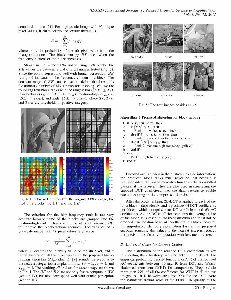
Shown in Fig. 4 for LENA image using 8×8 blocks, theBE values are between 2 and 6 in all images tested (Fig. 5).Since the colors correspond well with human perception, BEis a good indicator of the frequency content in a block. Theconstant range of BE can be used to define the thresholdsfor arbitrary number of block ranks for dropping. We use thefollowing four block ranks with the ranges: low (dBEe ≤ TL),low-medium (TL < dBEe ≤ TLM ), medium-high (TLM <dBEe ≤ TMH ), and high (dBEe > TMH ), where TL, TLM
and TMH are thresholds in positive integers.
2
2.5
3
3.5
4
4.5
5
5.5
500
1000
1500
2000
2500
3000
3500
4000
4500
5000
Fig. 4: Clockwise from top left: the original LENA image, thetiled 8×8 blocks, the BV , and the BE.
The criterion for the high-frequency rank is not veryaccurate because some of the blocks are grouped into themedium-high rank. It leads to the use of block variance BVto improve the block-ranking accuracy. The variance of agrayscale image with M pixel values is given by
V =1
M − 1
M∑i=1
(xi − x)2
where xi denotes the intensity value of the ith pixel, and xis the average of all the pixel values. In the proposed block-ranking algorithm (Algorithm 1), dxe rounds the scalar x tothe nearest integer towards plus infinity, TV = 1, TL = 3, andTLM = 4. The resulting BV values for LENA image are shownin Fig. 4. The BE and BV are not only fast to compute in HW(section IV), but also correspond well with human perception(section III).
BARBARA BOAT FRUITS
GOLDHILL MANDRILL PEPPER
Fig. 5: The test images besides LENA.
Algorithm 1 Proposed algorithm for block ranking
1: if dBV/100e ≤ TV then2: if dBEe ≤ TL then3: Rank 4: low frequency (blue)4: else if TL < dBEe ≤ TLM then5: Rank 3: low-medium frequency (green)6: else if dBEe > TLM then7: Rank 2: medium-high frequency (yellow)8: end if9: else
10: Rank 1: high frequency (red)11: end if
Encoded and included in the bitstream as side information,the produced block ranks must never be lost because itwill jeopardize the image reconstruction from the transmittedpackets at the receiver. They are also used in structuring theencoded DCT coefficients into the data packets to enablepacket dropping in the compressed domain.
After the block ranking, 2D-DCT is applied to each of theluma block independently, and it produces 64 DCT coefficientsper block, which comprise one DC coefficient and 63 ACcoefficients. As the DC coefficient contains the average valueof the block, it is essential for reconstruction and must not bedropped. The location of an AC coefficient in a block indicatesthe importance. The only information loss in the proposedencoder, rounding the values to the nearest integers reducesthe precision for faster computation with less memory use.
B. Universal Codes for Entropy Coding
The distribution of the rounded DCT coefficients is keyin encoding them losslessy and efficiently. Fig. 6 depicts theempirical probability density functions (PDFs) of the roundedAC coefficients between -10 and 10 from DCT and Walsh-Hadamard transform (WHT) for comparison. They includemore than 99% of all the coefficients for WHT in all the testimages, but it is between 80% and 99% for the DCT. Notethe symmetry around zeros in the PDFs. The quality of the
www.ijacsa.thesai.org 204| P a g e

(IJACSA) International Journal of Advanced Computer Science and Applications,Vol. 4, No. 12, 2013
−10 0 100
0.1
0.2
0.3
BARBARAP
roba
bilit
y
WHTDCT
−10 0 10
BOAT
−10 0 10
FRUITS
−10 0 10
GOLDHILL
−10 0 10
LENA
−10 0 10
MANDRILL
−10 0 10
PEPPER
Fig. 6: The empirical PDFs of the AC coefficients from DCT and WHT for the test images.
reconstructed images using DCT in peak-signal-to-noise ratio(PSNR) is always a few dB higher than that for WHT due tothe rounding of the DCT coefficients.
The probability of zeros is always less than 0.20 forDCT and slightly higher for WHT. Producing shorter averagelength of codewords with higher probability of zeros [23],the Huffman code is not efficient for this case. Moreover,the distribution of the DCT coefficients could not be knownbeforehand. The Huffman code is favored when more zeros arepresent in the high-frequency coefficients caused by strongerquantization.
The dropping of the DC coefficients starting from theleast important implies that RLE is not suitable for thiswork because it introduces more dependencies in the resultingbitsream. The run lengths of the coefficients can also be veryshort because of no quantization. This is a challenge becauseRLE can increase performance in lossless coding.
Furthermore, coding techniques that can only be decodedwhen the bitstream is complete, such as the Burrows-Wheelertransform (BWT) [3], are also not suitable. It is, in fact,impossible because the received stream at the end are truncateddue to dropping. Nevertheless, they are useful for encoding theblock ranks and the rounded differences after applying differ-ential pulse-code modulation (DPCM) to the DC coefficients.
Excellent texts such as [23] comprehensively discuss andcompare various coding techniques available. They lead us tothe use of universal codes (UCs) for entropy coding for the ap-plicability regardless of the data distribution. We propose usingthe Fraenkel and Klein C1 Fibonacci code [8] (FK1) based onthe comparison of well-known UCs in [7]. The recurrence rela-tion F (i) = F (i−1)+F (i−2) with seed values F (0) = 0 andF (1) = 1 defines the sequence F (i) of the famous Fibonaccinumbers. The Zeckendorf’s theorem states that any integer canbe formed as the sum of Fibonacci numbers [29]. Thus, for apositive integer number n, if d0, d1, ..., dk represent n, then wehave n =
∑k−1i=0 diFi+2 and dk = dk−1 = 1 where Fi is the ith
Fibonacci number. A Zeckendorf representation Z(n) is codedby writing a binary vector with a 1 wherever that Fibonaccinumber is included, but F1 is omitted due to redundancy.For example, since 19 = 13(F7) + 5(F5) + 1(F2), it means19 = (1×13)+(0×8)+(1×5)+(0×3)+(0×2)+(1×1)which gives Z(19) = 101001.
A very important property of Z(n) is that two adjacent 1’snever occur. Therefore, the FK1 code produces FK(n) bywriting Z(n) in the reverse order and appending another 1 asa terminating comma; hence, FK(19) = 1001011. Decodingn from FK(n) is straightforward and only involves additions,making it fast for HW implementation. Using the code forsigned integers is possible after bijection, i.e. mapping thereal values in signed integers into symbols in positive values.
Table I shows the FK1 codewords of the symbols n fromapplying bijection to the real values x.
TABLE I: Some examples of FK1(n) for symbols from realvalues after bijection
x n FK(n) x n FK(n)
0 1 11 3 6 100111 2 011 -3 7 01011-1 3 0011 4 8 0000112 4 1011 -4 9 100011-2 5 00011 ... ... ...
The FK1 code offers several advantages [7]. First, unlikeusing adaptive parametrized codes, storing tables of codewordsin the network nodes for packet dropping is unnecessary;hence, more efficient use of resources. Second, using two 1’s asthe delimiter between consecutive coded symbols gives morerobustness against transmission errors than table-based codessuch as the Huffman code. Third, because of the universalcodewords, simply reading from lookup tables (LUTs) allowsfast encoding and decoding. Fourth, the memory allocated forthe LUTs is also very small (section IV). Fifth, no prefix codeused also means higher efficiency.
The encoding strategy for the DCT coefficients and theblock ranks is proposed as follows. First, the block ranks areencoded in the raster fashion using BWT because only fourinteger symbols are used, which saves around 18% than using2-bit binary encoding. Using run lengths gives very little gain,merely around 0.01 kilobytes. The BWT is currently the bestlossless compression technique, especially for text, with fastimplementations available [23] such as the bzip2 [20].
Second, the AC coefficients are processed and encoded sep-arately from the DC. Prior to encoding, DPCM and bijectionare applied to the signed coefficients. The resulting symbolsfor the DC coefficients are then encoded into binary stringusing the FK1 code. The bitstream from the block ranks andthe DC coefficients must not be dropped.
Third, the 63 AC coefficients from each block are groupedinto 63 series according to their position, following the zigzagdirection as used in JPEG. The symbols after bijection areencoded in parallel using the FK1 code. The symmetry oftheir distribution (Fig. 6) motivates the use of bijection. Thecoefficients starting from the most top-left block are transmit-ted first in the raster fashion, and the series are sent accordingto their series number.
If the probability of zeros in the resulting binary string isvery high, i.e. higher than 0.9, the run lengths of ones andzeros can be encoded further, for example, using the Golombcodes [9]. In all the test images, however, the probability is
www.ijacsa.thesai.org 205| P a g e

(IJACSA) International Journal of Advanced Computer Science and Applications,Vol. 4, No. 12, 2013
only around 0.7. The bitstream from the Golomb code mustbe decoded before dropping. Since the reduced bitstream afterdropping must be encoded again using the Golomb code,processing time at the network nodes increases.
C. Data Structure and Packet Format
The data structure also affects the coding. The proposeddata structure depicted in Fig. 7 can be used to arrange theblocks, ranks and coefficients for encoding. Since all the ACcoefficients of the same rank and index are grouped together,dropping them as a group when necessary is straightforward.Packet dropping is fast because checking each block rank fordropping is not needed. Moreover, since the bitstream of thegroup is long, more compression gain can be achieved usingGolomb codes on the run lengths of the zeros. The proposedHW design and implementation of the DMP network nodealso obtain higher throughput with longer input bitstream. Thisarea opens many interesting questions for future work. For thiswork we use fixed-length packets.
Proposed data structure
1 2 3 4
5
9
13
6 7 8
10 11 12
14 15 16
0 1 5 6 14 15 27 28
2
3
9
10
20
21
35
4 7 13 16 26 29 42
8 12 17 25 30 41 43
11 18 24 31 40 44 53
19 23 32 39 45 52 54
22 33 38 46 51 55 60
34 37 47 50 56 59 61
36 48 49 57 58 62 63
44
33
22
11
Block ranks
(BR)
Transmission
AC coefficients
(RCB)
... ...115
111
81
72
61
51
121
111
102
92
161
152
143
134
1234Ranks (R)
1116
1112
... ...125
121
1216
1212
... ...1625
1621
16216
16212
... ...1635
1631
16316
16312
...
4113
414
4213
424
46213
4624
46313
4634
...
...
Rank 1
Rank 2
Rank 3
Rank 4
Fig. 7: Proposed data structure for packetization and transmis-sion of the encoded blocks, ranks, and DCT coefficients.
III. RESULTS AND DISCUSSION
Seven standard grayscale test images are used in the exper-iments. The results are produced using MATLAB, and the bzip2codec [20] is used for the BWT-based compression. All imagesexhibited in this section should be seen with magnification onscreen for the best perceptual quality.
The first two images in Fig. 8 depict the block maps ofLENA image using only entropy and that using the proposedblock-ranking method. Both maps have the same blue andgreen blocks, but not those in the other two colors. There aremore red blocks in the second image, for example on the edgesand in the area of the fur. This illustrates the importance ofthe block variance in ranking the blocks. It produces more redblocks because they are more sensitive to visual distortion.
Fig. 8 also displays four sets of areas according to thefour ranks produced by the proposed ranking method. Theyshow the high classification accuracy of the proposed ranking
(a) (b) (c)
(d) (e) (f)
Fig. 8: The four-rank block map of LENA image using onlyentropy (a) and that using the proposed ranking method (b).The image is decomposed into five ranks as follows (withdecreasing dropping priority): low frequency in blue (c), low-medium in green (d), medium-high in yellow (e), and high inred (f). Borders are added for better view.
method. Different techniques to classify the contents can beemployed, for example using edge and texture detection todetect the edges and the textured areas. This idea, however,is not necessary because the blocks containing them canbe successfully categorized as those in red by the proposedmethod.
The distribution of the four block ranks in the test images asshown in Fig. 9 indicates that all the rank maps of the imagescorrespond well with human perception. It can be checked byvisually comparing the distribution with the original imagesin Fig. 5. Rank-1 blocks are dominant in BARBARA, BOAT,GOLDHILL, and especially MANDRILL due to many texturedareas present therein. In the other images, the portions of theblocks of Rank 1 and Rank 3 are almost the same because ofthe flat areas (Rank 3) and the edges (Rank 1).
Barbara Boat Fruits Goldhill Lena Mandrill Pepper0
20
40
60
80
% B
lock
Ran
ks
R−4 R−3 R−2 R−1
Fig. 9: The distribution of the four ranks in the test images.
Some examples of the rank map and the reconstructedimages are shown in Fig. 10 from PEPPER image. Fig. 10(b) is reconstructed from the received bitstream without theDC coefficients of Rank 4 because they have been droppedcompletely. When the network capacity is reduced, the nodesstart dropping the AC coefficients of Rank 3 beginning fromthose of the 63th index. When all the AC coefficients of Rank3 have been dropped, the resulting image quality is shown in
www.ijacsa.thesai.org 206 | P a g e

(IJACSA) International Journal of Advanced Computer Science and Applications,Vol. 4, No. 12, 2013
(a) Ranks (b) 60.45 | 0.999 | 5.31
(c) 44.40 | 0.979 | 3.83 (d) 38.63 | 0.929 | 2.31
Fig. 10: The examples from PEPPER image: the rank map withentropy and variance (a); the images reconstructed without theDCT coefficients from Rank 4 (b), from Ranks 4 and 3 (c),and from Ranks 4, 3, and 2 (d). The PSNR (dB), MSSIM andbitrate (bpp) are provided underneath.
Fig. 10 (c). The dropping is continued until the worst qualityis achieved by reconstructing only from the DC coefficientsof all ranks (Fig. 10 (d)). The results are accompanied withthe bitrate in bits per pixel (bpp) as well as the PSNR and themean structure-similitary index (MSSIM) [30] as the objectiveVQ metrics. Furthermore, the rate-distortion plots using thetwo quality measures for the test images are shown in Fig. 11.The plots from JPEG are also provided for comparison.
The performance of the proposed scheme can be im-proved by using deblocking filter as post-processing step atthe receiver. An important role for estimating the bitrate,this step is conducted at the source in many image/videocoding techniques. Other possible improvements include intra-prediction, which is not considered here because it createsdependencies between the adjacent blocks and increase thecomplexity. Note again that we do not aim at better codingperformance than that of JPEG or even JPEG 2000.
Fig.10 shows that the reconstructed images suffer fromblocking artifacts that occur only at the blocks which ACcoefficients are dropped. The artifact, however, is differentfrom the typical blocking artifact in JPEG because the latteroccupies much larger areas consisting of many blocks. Thedistortion is called pixelation artifact due to the resemblanceto it. The encoded rank maps in the side information of thebitstream plays another important function; they inform thereceiver of the exact locations of the pixelated blocks. Thusthose blocks can be directly restored without searching theirlocations as in typical deblocking algorithms.
For the worst distortion because all the AC coefficientsare discarded, a fast depixelization algorithm is proposed inAlgorithm 2 which refers to Fig. 12. Fig. 13 shows someexamples of the depixelization for FRUIT and PEPPER imageswith PSNR and MSSIM values. The algorithm successfullyrestores the flattened blocks to be more appealing to humanperception.
The blocks of Rank 2, 3 and 4 can be reconstructed onlyfrom the DC coefficients without pixelated blocks because theycan be repaired fast using Algorithm 2 (Fig. 13). In fact, Rank-1 blocks with strong textures and no edges can be made freefrom pixelation. Nevertheless, the artifacts are still visible inRank-1 blocks with edges even after depixelization. Repairingthe pixelated edges can benefit from more advanced techniquessuch as in [13].
Fig. 14 (left) shows a collaborating person as a segmentedobject from a video frame of an HD test video sequencefrom [26]. It is expected to be produced by the camerason a surface of a CS. Applying the proposed block rankingalgorithm produces the blocks in Fig. 14 (right). The blocksof the background can be assigned an additional rank, for
0 2 4 630
40
50
60
PS
NR
(dB
)
Bitrate (bpp)
BARBARA
DMP R−4DMP R−3DMP R−2DMP R−1JPEG
0 2 4 6Bitrate (bpp)
BOAT
0 2 4 6Bitrate (bpp)
FRUITS
0 2 4 6Bitrate (bpp)
GOLDHILL
0 2 4 6Bitrate (bpp)
LENA
0 2 4 6 8Bitrate (bpp)
MANDRILL
0 2 4 6Bitrate (bpp)
PEPPER
0 2 4 60.5
0.6
0.7
0.8
0.9
1
MS
SIM
Bitrate (bpp)
BARBARA
DMP R−4DMP R−3DMP R−2DMP R−1JPEG
0 2 4 6Bitrate (bpp)
BOAT
0 2 4 6Bitrate (bpp)
FRUITS
0 2 4 6Bitrate (bpp)
GOLDHILL
0 2 4 6Bitrate (bpp)
LENA
0 2 4 6 8Bitrate (bpp)
MANDRILL
0 2 4 6Bitrate (bpp)
PEPPER
Fig. 11: The rate-distortion plots of PSNR (top) and MSSIM (bottom) against bitrate in bits per pixel (bpp).
www.ijacsa.thesai.org 207| P a g e

(IJACSA) International Journal of Advanced Computer Science and Applications,Vol. 4, No. 12, 2013
D11 D12 D13 D14
D21
D31
D41
D
D22 D23 D24
D32 D33 D34
D42 D43 D44
B B14
B51
B61
B71
B81
B52 B53 B54
B62 B63 B64
B72 B73 B74
B82 B83 B84
a ab1 ab2 ab3 ab4 ab5 ab6 b
ac2
ac1
ac3
ac4
ac5
ac6
c
ax2 abx21 abx22 abx23 abx24 bx2 bd1
acx21 ax1 abx11 abx12 bx1 bdx21 bd2
acx22 acx11 x x bdx11 bdx22 bd3
acx23 acx12 x x bdx12 bdx23 bd4
acx24 cx1 cdx11 cdx12 dx1 bdx24 bd5
cx2 cdx21 cdx22 cdx23 cdx24 dx2 bd6
cd1 cd2 cd3 cd4 cd5 cd6 d
A A15
A51 A55 A56 A57 A58
A65 A66 A67 A68
A75 A76 A77 A78
A85 A86 A87 A88
C15 C16 C17 C18
C41
C
C25 C26 C27 C28
C35 C36 C37 C38
C45 C46 C47 C48
Subblocks A, B, C, D
Fig. 12: The proposed depixelization in Algorithm 2.
Algorithm 2 A depixelization algorithm for the worst distor-tion
1: Reference elements of the subblocks A,B,C and D2: X ← (A88 +B81 + C18 +D11)/43: a← A55, b← B54, c← C45, d← D44
4: for Block M = {A,B,C,D} do5: {m,mx1,mx2, X} ← LI(m,X, 2)6: end for7:8: Non-reference elements of the subblocks A,B,C and D9: if Rank of block A ≥ TR and CA ≤ TC then
10: if Rank of block B ≥ TR and CB ≤ TC then11: {a, ab1, ..., ab6, b} ← LI(a, b, 6)12: {ax2, abx21, ..., abx24, bx2} ← LI(ax2, bx2, 4)13: {ax1, abx11, abx12, bx1} ← LI(ax1, bx1, 2)14: else if Rank of block B ≥ TR and CB > TC then15: {a, ab1, ab2, ab3, B51} ← LI(a,B51, 3)16: {ax2, abx21, abx22, B61} ← LI(ax2, B61, 2)17: {ax1, abx11, B71} ← LI(ax1, B71, 1)18: end if19: end if20: Run Steps 10-18 to compute the elements with suffix ac−21: Compute the elements of subblocks B,C and D with the logic
as in Steps 9-2022:23: Terminal elements in boundary blocks such as block A24: if Rank of block A ≥ TR and CA ≤ TC then25: Non-corner elements Aij (i=1:4, j=5:8; i=5:8, j=1:4)26: for i = 1 to 4 do27: {Ai5, ..., Ai8} ← {a, ab1, ab2, ab3}28: {A5i, ..., A8i} ← {a, ac1, ac2, ac3}29: end for30: Corner elements Aij (i=1:4, j=1:4)31: for i = 1 to 4 do32: {A11, A22, ..., A55} ← LI(A11, A55, 3)33: Compute the other non-corner elements with the logic as
in Steps 15-1734: end for35: end if
example, Rank 5. They contribute an insignificant increase inbits (much less than 1 Kbits) and their DCT coefficients areall discarded. This illustrates that the proposed scheme canencode regions-of-interest with arbitrary shapes.
33.36 | 0.732 | 0.19 33.43 | 0.769
32.21 | 0.740 | 0.20 32.28 | 0.805
Fig. 13: Some examples of the worst distortion (left) and theimproved quality after de-pixelization (right) for FRUIT (top)and PEPPER (bottom) images. The numbers denote PSNR andMSSIM, respectively.
Fig. 14: An image with a segmented object as part of a videoframe from a CS’s surface (left). The blocks after applyingthe proposed block ranking algorithm (right). Image border isadded for better view by readers.
IV. ALGORITHM COMPLEXITY AND FPGA DESIGN
We have proposed an FPGA-based platform for the designand implementation of a DMP network node [31] (Fig. 15).It provides a detailed introduction to the platform architectureand the simulation-implementation environment for the design.Our compact implementation on a Xilinx Virtex-6 ML605board consumes very small amount of the available resources.Moreover, the elementary operations in our implementationtake (much) less than 5 µs as desired to meet the low-latency
www.ijacsa.thesai.org 208| P a g e

(IJACSA) International Journal of Advanced Computer Science and Applications,Vol. 4, No. 12, 2013
PCIe controller
AXI memory mapped bus
Interrupt controller Microblaze
DMA controller
Transform
DMA controller
Encoding
DMA controller
Block ranking
Memorycontroller
DMA controller
Block ranking Transform DPCM Encoding
Para
llel
Pipe
line
Fig. 15: The FPGA-based architecture of a DMP transmitterwith the pipeline and parallel approaches.
requirement. The AXI bus and the EDK environment areused to implement both the transmitter and receiver in DMP.Although the architecture of the access node has differentnumber of compression-scheme components than that of thenetwork node, their core components and adopted processingapproach are the same. In addition to controlling the dataflow within the FPGA system, Microblaze is also used toestablish and maintain the communication with the externalDMP servers located on a host (PC machine).
The design’s modularity and scalability ease the integra-tion of the external modules into the platform, which canfollow parallel, pipeline or hybrid approaches. The first twoapproaches are depicted in Fig. 15. By assuming equal ac-cess in the memory-mapped AXI bus, the parallel approachoffers flexibility because it permits software elimination incertain steps of the processing chain if necessary, e.g. theencoding. This is possible because the Microblaze governs allthe execution steps of the chain, and they are independentlyconnected to a single AXI bus. On the other hand, the pipelineimplementation is more efficient provided that all the modulesare used in the processing chain and the pipeline latency is notcritical. Adopting both approaches in a hybrid fashion is alsoan alternative depending on the application.
A. Calculation of Entropy
The complexity for HW design of the major parts of theproposed system is presented as follows. Fig. 16 (a) showsthe entropy module, and the dashed line covers the parallelstructure. The logarithm operation can be implemented asa registered LUT for 8-bit input data at one clock (CLK)[2]. Thus, the overall latency is 7 CLK, i.e. 3 CLK foreach multiplier, and given n parallel structures, it becomes1 + 3log(n) clocks. Consisting of a block RAM (BRAM)memory and an incremental logic, a histogram module with64 input integer values provides the probability values pi.
Fig. 16 (b) and (c) show the simplified and real diagrams,respectively. The input data for the evaluation of the histogramaddress the BRAM and the BRAM’s Dout stores the count ofDatain’s prior to the occurrences at the BRAM address bus.The counter is incremented by one and written back to theBRAM at the same address. The BRAM limits the calculationspeed as the output data is one CLK delayed with respect to
pn
pn+1
pnxn
x
E
pn+1xn+1
pn+2xn+2
pn+3xn+3
V
(a)
(d)
(e) (f)pnxpnx
pn-1xpnx
... inv
...
...
log2
delay
log2
delay
ping-pongbuffer
1DDCT
BRAM
BRAM
sub
sub
sub
sub
BRAMAdr
Datain
+1Din
Dout
(b)
Datain
+1
Dataout
FF
Address (c)
Adr0
Dout0
Din1
Dout1
Adr1
Fig. 16: The modules for calculating entropy (a), histogram(b,c), mean(d), variance (e), and 2D-DCT (f).
the address bus (a synchronous memory data read); hence,evaluating a single input pixel involves two CLK. Strongparallelization of the computations is possible [12], and thehistogram computation needs 34 LUTs and 23 FFs.
B. Calculation of Mean and Variance
Computing mean values of n inputs of pixi (Fig. 16(d)) takes 3+log(n) CLK, and the variance-calculation moduleconsists of the mean-calculation unit and a set of subtractors,multipliers and adders. They are strongly parallel moduleswhich process the data every clock cycle. The parallelizationdetermines the computation time, and generally it is 4+log(n)CLK plus the latency from the mean-calculation module.
C. Calculation of 2D-DCT, IDCT and DPCM
By employing a two-pass 1D-DCT transform [28], com-puting a complete 8 × 8 2D-DCT takes 80 clock cycles andcan work at 107 MHz. Adopting a ping-pong fashion, it storesthe results of the 1D-DCT by means of an intermediate buffer(Fig. 16 (f)). It is a trade-off between resource consumptionand speed which complies well with the idea of an AXI-based Microblaze-controlled architecture. Nevertheless, otherimplementation approaches for 2D-DCT can be considered,such as replacing the time-consuming multiplications withLUT accesses [14]. As for the DPCM, its sequential executionflow favors software implementation in Microblaze, and theprocessing power will not be absorbed because DC coefficientsare fewer than AC coefficients.
D. Encoding and Decoding
Encoding Fibonacci code is simple, but straightforwardimplementation in iterative procedures needs substantial clock
www.ijacsa.thesai.org 209| P a g e

(IJACSA) International Journal of Advanced Computer Science and Applications,Vol. 4, No. 12, 2013
cycles. Therefore, it is better implemented as LUT and exe-cuted in one clock, which is feasible because Fibonacci coderfor 8-bit numbers consumes merely 8×12 bits, and 3072 bitscan fit into a single BRAM memory of 18 Kbits. Thus, itoccupies only 2 BRAMs for both encoding and decoding.Moreover, the bzip2 algorithm can be implemented in softwarein Microblaze.
E. Packet Dropping
The dropping module in Fig. 17 is the core componentof the QS scheme in a DMP node. The module is integratedto the platform in Fig. 15 also via a direct memory access(DMA) controller. Our strategy is to extensively use AXIS(AXI Streaming) bus which provides system flexibility. All themodules connected to the network node are AXIS-compatible.
Streaming input Comparator BRAM Streaming
output
Control FSM
Memory-mapped interface Dropping
threshold
Counter
Fig. 17: The proposed structure for DMP dropping module.
The dropping module works as follows. The networkpackets carrying image data are sent over the PCIe to theexternal memory (DDR3 in ML605) and stored on a longqueue. The Microblaze monitors the status of the queue,programs DMA controller to read the data from the externalmemory, and writes them to the dropping module. Based onthe data received from the other nodes in the network, acurrent threshold value for dropping is computed and writtento the internal register of the dropping module. The data fedinto the dropping module from the external memory by theDMA are either dropped or passed through to the internalmemory (BRAM) after compared with the threshold. Once theDMA write-operation is finished, the Microblaze is interruptedand informed that the dropping statistics can be read fromthe internal register of the dropping module. The Microblazethen programs the DMA controller based on the statistics, andthe data stored in the internal memory are transferred to theexternal memory. The dropping process is finished when thedata is read from the internal memory of the dropping moduleand written to the external RAM. All HW modules in bothaccess and network nodes are interconnected with AXIS busand controlled by the Microblaze.
F. Depixelization as Post-Processing
Depixelization is essentially a finite-impulse response(FIR) filter operation conducted on block borders. Xilinxdelivers a FIR compiler tool which can be used to compilethe FIR architectures to generate the depixelization filter [38].It includes 12-bit coefficients and 60-tap input data which canwork at 150 MHz and consume 3382 LUT-FF pairs.
G. Overall Performance
The system performance strictly depends on the chosenarchitecture (parallel, pipeline or hybrid) and the synchro-nization between the modules. The following is the grossestimate of the computational time for processing a videoframe as a 1920×1080 color image. By assuming 256-bitAXI bus width, 64-pixel block, and 100 MHz FGPA clockcycle as the main constraints, the internal processing speedper single thread becomes 50 Mblocks/s. As the luma and 25%subsampled chroma images equal 48,600 blocks, the essentialprocessing time becomes 1 ms per frame. Since the object-based processing reduces the number of blocks processed perframe, the processing time per frame is less than 1 ms.
The consumed resources are detailed in Table II, and theadditional pre- and post-processing steps are excluded. LUTsconsume the most resources which are roughly 10% of all theXCVLX240T resources, the FPGA used in ML605 [36]. It ispossible to balance the usage of LUTs with DSP implementa-tion to equalize resource consumption. Consequently, 15 to 20parallel processing streams can be implemented as in Fig. 15which reduce the processing time to approximately 50 µs perframe. Moreover, several FPGA boards can be used as a one-stop system [16] to achieve chip-level parallelism.
TABLE II: Total consumption of resources
Module #LUT #FF #BRAM
Entropy m·log(m)·115 + n · 19 110 + n · 64 0Histogram 34 23 1Variance n · 115 + [n + n·log(n)] · 8 n · 110 0
DCT 123 110 2Fibonacci 0 0 2
m denotes the number of parallel inputs for entropy module
V. CONCLUSION AND FUTURE WORK
We have presented an ultrafast, DCT-based, embeddedimage-compression scheme which is quality scalable and canprocess objects with arbitrary shapes. It is designed for networkarchitecture such as DMP that guarantees maximum EED.The encoder mainly consists of block ranking, 2D-DCT andentropy coding. As the quantization as in existing imagecoding schemes is not present, the main loss of informationin this approach is due to the intelligent dropping of datapackets by network nodes during transmission to guaranteelocal delay. Since simplicity and parallelization are favoredfor minimizing processing time, block entropy and varianceare used for block ranking, which work satisfactorily byyielding four ranks of 8×8-blocks with increasing importance.Universal codes are employed to encode the resulting blockranks and DCT coefficients. The VQ in PSNR and MSSIMof several common test images due to dropping is givenagainst the bitrates, which are also compared to the resultsfrom JPEG. JPEG performs better as expected because it canexploit global redundancies in an image and the bitstream,but lacks the scalability. Fundamental differences between thetwo schemes make such a performance comparison essentiallyirrelevant. Excessive dropping results in pixelation artifacts thatare faithfully contained in the blocks which the receiver canimmediately locate from the side information available in the
www.ijacsa.thesai.org 210| P a g e

(IJACSA) International Journal of Advanced Computer Science and Applications,Vol. 4, No. 12, 2013
packet headers of the remaining bitstream. A depixelizationalgorithm, a post-processing step at the receiver, is proposedfor the worst distortion. We show how the scheme can beapplied to objects of arbitrary non-rectangular areas in imagesafter segmentation. Every video frame, channel, segmentedobject, and block are processed independently, allowing fullyparallel HW implementation. Finally, as indicated by theestimated complexity and resource consumption of the pro-posed scheme for FPGA implementation, a video frame asa 1920×1080 color image can be processed, encoded anddecoded in less than 1ms, sufficient to meet the maximum EEDat 11.5ms. Ideas for further performance improvement includeincorporating fast intra-prediction and advanced depixelization.
REFERENCES
[1] N. Ahmed, T. Natarajan, R. K. Rao, ”Discrete cosine transform,” IEEETrans. Computers, vol. 23, no. 1, pp. 90–93, 1974.
[2] N. Alachiotis, A. Stamatakis, ”Efficient floating-point logarithm unit forFPGAs,” in Proc. IEEE Int’l Sym. Parallel & Distributed Processing,Workshops and PhD Forum (IPDPSW), 2010.
[3] M. Burrows, D. Wheeler, A Block Sorting Lossless Data CompressionAlgorithm, Technical Report 124, Digital Equipment Corporation, 1994.
[4] C. Chafe, M. Gurevich, G. Leslie, S. Tyan, ”Effect of time delay onensemble accuracy,” in Proc. Int’l Symp. Music Acoustics, 2004.
[5] T.A. DeFanti, D. Acevedo, R.A. Ainsworth, M.D. Brown, S. Cutchin,G. Dawe, K.U. Doerr, A. Johnson, C. Knox, R. Kooima, F. Kuester,J. Leigh, L. Long, P. Otto, V. Petrovic, K. Ponto, A. Prudhomme,R. Rao, L. Renambot, D.J. Sandin, J.P. Schulze, L. Smarr, M. Srini-vasan, P. Weber, G. Wickham, ”The future of the CAVE,” CentralEuropean J. Eng., vol. 1, no. 1, pp. 16–37, 2011.
[6] Y. Du, J. Wang, S.-M. Guo, P.D. Thouin, ”Survey and comparativeanalysis of entropy and relative entropy thresholding techniques,” IEEProc. - Vision, Image and Signal Processing, vol. 153, no. 6, pp. 837–850, 2006.
[7] P. Fenwick, Universal Codes, in K. Sayood (ed.), Lossless CompressionHandbook, Academic Press, 2003.
[8] A.S. Fraenkel, S.T. Klein, ”Robust universal complete codes for trans-mission and compression,” Discrete Applied Mathematics, vol. 64, no.1, pp. 31–55, 1996.
[9] S. W. Golomb, ”Run-length encodings,” IEEE Trans. InformationTheory, vol. 12, no. 3, pp. 399–400, 1966.
[10] P. Holub, J. Matela, M. Pulec, M. Srom, ”Ultragrid: low-latency high-quality video transmissions on commodity hardware,” in Proc. ACMMultimedia, 2012, pp. 1457–1460.
[11] Advanced Video Coding for Generic Audio-Visual Services, ITU-T Rec.H.264 and ISO/IEC 14496-10 (AVC), ITU-T and ISO/IEC JTC 1, May2003 (and subsequent editions).
[12] E. Jamro, M. Wielgosz, K. Wiatr, ”FPGA implementaton of stronglyparallel histogram equalization,” in Proc. IEEE Design and Diagnosticsof Electronic Circuits and Systems (DDECS), 2007, pp. 1–6.
[13] J. Kopf, D. Lischinski, ”Depixelizing pixel art,” ACM Trans. Graphics,vol.30, no. 4, pp. 99:1–99:8, 2011.
[14] R. Kutka, ”Fast computation of DCT by statistic adapted look-uptables,” in Proc. IEEE Int’l Conf. Multimedia and Expo (ICME), 2002,pp. 781–784.
[15] J-R. Ohm, ”Advances in scalable video coding,” Proc. IEEE, vol. 93,vol. 1, pp. 42–56, 2005.
[16] One Stop Systems, http://www.onestopsystems.com/[17] L. A. Rønningen, The Distributed Multimedia Plays Architecture (ver-
sion 3.20), Technical Report, ITEM, NTNU, 2011.[18] L.A. Rønningen, O.J. Wittner, ”Experiments on remote conducting
between Trondheim and Lisbon,” ITEM, NTNU, 2011.[19] H. Schwarz, D. Marpe, T. Wiegand, ”Overview of the scalable video
coding extension of the H.264/AVC standard,” IEEE Trans. CircuitsSyst. Video Technol., vol. 17, no. 9, pp. 1103–1120, 2007.
[20] J. Seward, bzip2 codec, http://www.bzip.org/[21] C. E. Shannon, ”A mathematical theory of communication,” Bell System
Technical Journal, vol. 27, no. 3, pp. 379–423, 1948.[22] J. M. Shapiro, ”Embedded image coding using zerotrees of wavelet
coefficients,” IEEE Trans. Signal Processing, vol. 41, no. 12, pp. 3445–3462, 1993.
[23] D. Solomon, G. Motta, Handbook of Data Compression, Springer, 2010.[24] G. Sorwar, A. Abraham, L.S. Dooley, ”Texture classification based on
DCT and soft computing,” in Proc. 10th IEEE Int’l Conf. Fuzzy Systems,2001.
[25] H. Sun, A. Vetro, J. Xin, ”An overview of scalable video streaming,”Wireless Communications and Mobile Computing, vol. 7, pp. 159–172,2007.
[26] TGFX. http://www.timelinegfx.com/.[27] R. Tucker, ”The role of optics and electronics in high-capacity routers,”
J. Lightwave Tech., vol. 24, no. 12, pp. 4655–4673, 2006.[28] A. Tumeo, M. Monchiero, G. Palermo, F. Ferrandi, D. Sciuto, ”A
pipelined fast 2D-DCT accelerator for FPGA-based SoCs,” in Proc.IEEE Computer Society Annual Symp. VLSI, 2007, pp. 331–336.
[29] S. Vajda, Fibonacci and Lucas Numbers, and the Golden Section Theoryand Applications, Ellis Horwood, Chichester, 1989.
[30] Z. Wang, A. C. Bovik, H. R. Sheikh, E. P. Simoncelli, ”Image qualityassessment: from error visibility to structural similarity,” IEEE Trans.Image Processing, vol. 13, pp. 600–612, 2004.
[31] M. Wielgosz, M. Panggabean, J. Wang, L. A. Rønningen, ”An FPGA-based platform for a network architecture with delay guarantee,” J.Circuits, Systems and Computers, vol. 22, no. 06, 2013.
[32] P. Schelkens, A. Skodras, T. Ebrahimi, The JPEG 2000 Suite, Wiley,Series: Wiley-IS&T Series in Imaging Science and Technology 2009.
[33] D. Taubman, ”High performance scalable image compression withEBCOT,” IEEE Trans. Image Processing, vol. 9, no. 7, pp. 1158–1170,2000.
[34] D. Taubman, M. Marcellin, JPEG 2000: Image Compression Funda-mentals, Standards and Practice, Kluwer Academic Publishers, 2001.
[35] R.J. Van der Vleuten, R.P. Kleihorst, C. Hentschel, ”Low-compexityscalable DCT image compression,” in Proc. IEEE Int’l Conf. ImageProcessing, 2000, pp. 837–840.
[36] Virtex series, http://www.xilinx.com/publications/matrix/Virtex Series.pdf[37] D. Wu, Y. Hou, Y-Q. Zhang, ”Transporting real-time video over the
Internet: challenges and approaches,” Proc. IEEE, vol. 88, no. 12, pp.1855–1875, 2000.
[38] Xilinx, http://www.xilinx.com/support/documentation/ip documentation/fir compiler ds534.pdf
[39] x264, http://www.videolan.org/developers/x264.html[40] Z. Yang, B. Yu, W. Wu, K. Nahrstedt, R. Diankov, R. Bajscy, ”A study
of collaborative dancing in tele-immersive environments,” in Proc. 8thIEEE Int’l Symp. Multimedia, 2006, pp. 177–184.
[41] J. Zhang, T. Tan, ”Brief review of invariant texture analysis methods,”Pattern Recognition, vol. 35, no. 3, pp. 735–747, 2002.
www.ijacsa.thesai.org 211| P a g e
Related Documents