Journal of Instrumentation OPEN ACCESS Ultrafast emission from colloidal nanocrystals under pulsed X-ray excitation To cite this article: R.M. Turtos et al 2016 JINST 11 P10015 View the article online for updates and enhancements. You may also like Crafting Semiconductor Organic-inorganic Nanocomposites Via Placing Conjugated Polymers in Intimate Contact with Nanocrystals for Hybrid Solar Cells Zhiqun Lin, Jaehan Jung, Youngjun Yoon et al. - Photoelectrochemical and Surface Analysis of CdSe-Poma Composites on Highly Organized Pyrolytic Graphite Stephanie Dulovic, Sophia Maria Casto, Justyna Widera et al. - Direct Evaluation about Structure and Optical Property of Individual Multi-Shell Quantum Dot By TEM Masato Uehara, Yohei Sato and Masami Terauchi - This content was downloaded from IP address 65.21.229.84 on 10/09/2022 at 05:28

Welcome message from author
This document is posted to help you gain knowledge. Please leave a comment to let me know what you think about it! Share it to your friends and learn new things together.
Transcript

Journal of Instrumentation
OPEN ACCESS
Ultrafast emission from colloidal nanocrystalsunder pulsed X-ray excitationTo cite this article RM Turtos et al 2016 JINST 11 P10015
View the article online for updates and enhancements
You may also likeCrafting Semiconductor Organic-inorganicNanocomposites Via Placing ConjugatedPolymers in Intimate Contact withNanocrystals for Hybrid Solar CellsZhiqun Lin Jaehan Jung Youngjun Yoonet al
-
Photoelectrochemical and SurfaceAnalysis of CdSe-Poma Composites onHighly Organized Pyrolytic GraphiteStephanie Dulovic Sophia Maria CastoJustyna Widera et al
-
Direct Evaluation about Structure andOptical Property of Individual Multi-ShellQuantum Dot By TEMMasato Uehara Yohei Sato and MasamiTerauchi
-
This content was downloaded from IP address 652122984 on 10092022 at 0528
2016 JINST 11 P10015
Published by IOP Publishing for Sissa MedialabReceived June 21 2016
Revised September 26 2016Accepted October 10 2016
Published October 19 2016
Ultrafast emission from colloidal nanocrystals underpulsed X-ray excitation
RM Turtosa S Gundackerd A Polovitsynbc S Christodouloubc M Salomonia
E Auffrayd I Moreelsb P Lecoqd and JQ Grime1
aUniversitagrave degli Studi di Milano BicoccaPiazza dellrsquoAteneo Nuovo 1 20126 Milano Italy
bIstituto Italiano di Tecnologiavia Morego 30 IT-16163 Genova Italy
cDepartment of Physics University of Genoavia Dodecaneso 33 IT-16146 Genova Italy
dCERN1211 Geneve 23 Switzerland
eUS Naval Research LaboratoryWashington DC 20375 USA
E-mail joelgrimnrlnavymil
Abstract Fast timing has emerged as a critical requirement for radiation detection in medical andhigh energy physics motivating the search for scintillatormaterialswith high light yield and fast timeresponse However light emission rates from conventional scintillation mechanisms fundamentallylimit the achievable time resolution which is presently at least one order of magnitude slower thanrequired for next-generation detectors One solution to this challenge is to generate an intenseprompt signal in response to ionizing radiation In this paper we present colloidal semiconductornanocrystals (NCs) as promising prompt photon sources We investigate two classes of NCs two-dimensional CdSe nanoplatelets (NPLs) and spherical CdSeCdS coregiant shell quantum dots(GS QDs) We demonstrate that the emission rates of these NCs under pulsed X-ray excitation aremuch faster than traditional mechanisms in bulk scintillators ie 5d-4f transitions CdSe NPLshave a sub-100 ps effective decay time of 77 ps and CdSeCdS GS QDs exhibit a sub-ns value of849 ps Further the respective CdSe NPL and CdSeCdS GS QD X-ray excited photoluminescencehave the emission characteristics of excitons (X) and multiexcitons (MX) with the MXs providingadditional prospects for fast timing with substantially shorter lifetimes
Keywords Timing detectors Hybrid detectors Materials for solid-state detectors Scintillatorsscintillation and light emission processes (solid gas and liquid scintillators)
1Corresponding author
copy CERN 2016 published under the terms of the Creative Commons Attribution 30License by IOP Publishing Ltd and Sissa Medialab srl Any further distribution of this
work must maintain attribution to the author(s) and the published articlersquos title journal citation and DOIdoi1010881748-02211110P10015
2016 JINST 11 P10015
Contents
1 Introduction 1
2 Materials and methods 3
3 Results 631 Laser excitation of NC thin films 632 X-ray excitation of NC thin films 6
321 CdSe nanoplatelets 6322 CdSeCdS giant shell quantum dots 7
33 Nanocrystal and bulk scintillator heterostructures 9331 CdSe NPLs deposited on LSOCe 9332 CdSeCdS GS QDs deposited on LuAGCe 9
34 NCs light yield estimations 10
4 Discussion 11
5 Conclusion and outlook 14
1 Introduction
Over the last few decades radiation detector research has largely been directed toward the discoveryand development of scintillators with improved energy resolution via increased light yield andbetter proportionality [1 2] More recently generating a prompt response to the passage ofionizing particles has emerged as a critical requirement for next-generation radiation detectorsnotably in high energy physics (HEP) and time-of-flight positron emission tomography (TOF-PET)applications [3] In the search for rare events in the planned High Luminosity Large Hadron Collider(HL-LHC) for example event discrimination will require a sub-20 ps time resolution to mitigatepile-up events produced by the high luminosity of particle bunches ie gt 1 times 1035 cmminus2sminus1 [4]Similarly precise time-tagging of 511 keV γminusrays is required in TOF-PET in order to confine theannihilation point along the line of response (LOR) [5 6] and improve the signal to noise ratio
State-of-the-art coincidence time resolution (CTR) values on the order of 117 plusmn 3 ps have beenachieved for 20 mm long LSOCe Ca co-doped crystals using 511 keV [7] γminusrays which translatesinto a background rejection area of the order of a few centimeters Reaching the millimeter levelfor vertex identification however necessitates CTR values of 10 ps or less Reducing CTR valuescan be achieved via increasing the light yield shortening scintillation signal rise and decay timesor introducing a strong prompt signal [3] The intrinsic light yield measured for LYSO crystals is40 000 PhMeV plusmn 10 (syst) plusmn 3 (stat) under minimum ionizing electron excitation [8] and thedecay times in cerium doped systems are limited to 16ns [9] This sets a limit to the improvement
ndash 1 ndash
2016 JINST 11 P10015
a) b)
Figure 1 Cramegraver-Rao lower bound calculations for CTR using a LSOCe scintillator of (a) 3 mm and (b) 20mm length as function of SPTR and number of prompt photons
that photostatistics can bring to CTR measurements requiring that new approaches to achieving aprompt photo-response must be explored Figure 1 presents Cragravemer-Rao lower bound calculationsfor CTR values as a function of the single photon time resolution (SPTR expressed in sigma) andnumber of prompt photons produced along with the scintillation emission in the crystal For thecalculations shown we used the time profile of LSOCe ie scintillation rise time of τr = 70 psand decay time of τd = 40 ns and crystals of 3 mm and 20 mm lengths with different light transferefficiencies (LTEs) As shown in ref [3] and figure 1 a coincidence time resolution of 10 ps FWHMcan be achieved with a prompt signal of several hundreds of photons provided that the SPTR ofthe SiPM is of the order of 10 ps sigma Commercially available SiPMs do not provide this valuehowever measurements performed on free standing single photon avalanche diodes of the SiPMshowed SPTR values below 10 ps sigma Consequently SiPM engineering has to be improvedtogether with light production mechanisms as discussed in this paper to reach CTR values of 10ps
Processes such as the Cerenkov effect [10ndash12] and hot-intraband emission [13 14] have beeninvestigated for this purpose though both are low light yield processes This motivates research notonly towards ultrafast sub-nanosecond performance but also to materials that have the potential toproduce prompt photons with sufficiently high yield under ionizing irradiation
Here we present ultrafast emission dynamics of colloidal semiconductor nanocrystals (NCs)as a new approach for prompt photon generation In figure 2 the fast rise and decay for CdSenanoplatelets (NPLs) and CdSeCdS giant shell quantum dots (GS QDs) contrasted with the slowerdynamics of LSOCe under pulsed X-ray excitation provides clear motivation for this work CdSeNPLs are solution-processed quantumwells that are characterized by strong quantum confinement inonly one dimension Weak confinement in the lateral dimensions has two important consequencesFirst in contrast to spherical NCs momentum conservation rules apply more strictly which reducesaccessible states for Auger transitions Second a collective phasing of dipoles over many unit cellspermits a giant oscillator strength transition (GOST) [15ndash17] resulting in ultrafast emission ratesWe also investigate spherical GSQDs In addition to better photostability compared to the core-onlyCdSe NPLs their reduced emissionabsorption band overlap (see figure 3(b)) will be advantageousin real devices where light has to potentially travel through at least 20 mm of material before itis detected
ndash 2 ndash
2016 JINST 11 P10015
Figure 2 (a) Time-resolved photoluminescence and (b) steady-state spectra for LSOCe CdSeCdS GSQDs and CdSe NPLs under pulsed X-ray excitation
The tunable optoelectronic properties of NCs combined with recent advances in controllingtheir size shape coreshell heterostructure and surface chemistry have enabled their use in awide range of photonic applications They have shown particular promise for bio-labeling [18]low-threshold lasing [17 19 20] photovoltaics [21] and single photon sources for quantum infor-mation [22 23] The high quantum yields (QYs) of NC quantum dots (QDs) has also generatedinterest in their use as low-cost high-resolution scintillators for radiation detection [24ndash26] To-ward this end the response of QDs under high energy electron [27] alpha [28] soft X-ray [29] andγ-ray [30] irradiation has been investigated Initial high energy excitation studies have highlightedseveral important challenges that all degrade the light emitting properties of NCs notably nonradia-tive Auger recombination [27] photo-instability [31] and losses due to the reabsorption of emittedlight [30] These challenges arise from the nature of NCs as small 100 nm semiconductors Onthis size scale strong carrier confinement results in efficient Auger recombination high surface tovolume ratios makes them sensitive to the external environment and damage and small Stokes shiftsresult in significant reabsorption of emitted light All of these issues degrade the performance ofscintillators For instance nonlinear quenching such as Auger recombination that occurs at the highcarrier densities created at electron track ends has been identified as a major cause of scintillatornonproportionality [9 32 33] and therefore degraded energy resolution
Fortunately significant effort has been devoted to overcoming these barriers to advance thedevelopment of NCs for the photonic applications mentioned above Auger recombination forexample has been mitigated with 2D nanoplatelets (NPLs) [17 34] and heterostructured coreshellNCs [35] Similarly CdSeCdS coreshell and particularly coregiant shell QDs (GS QDs) haveimproved photostability due to reduced charge transfer to deep nonradiative surface traps Furtherreabsorption can be circumvented by engineering large Stokes shifts in GS QDs where emissionfrom a CdSe QD core and absorption from the larger band gap CdS shell are well-separated [21 35]
2 Materials and methods
Details of the synthesis for the NPLs andGSQDs can be found in ref [17] and ref [36] respectivelyThe absorption and emission spectra and illustrations of the CdSe NPLs and CdSeCdS GS QDsused in this work are shown in figure 3 These spectra are typical of these NCs and depict several
ndash 3 ndash
2016 JINST 11 P10015
Figure 3 Absorption (black) and photoluminescence (green and red) spectra for (a) CdSe NPLs and (b)CdSeCdS GS QDs
of the characteristic features discussed above For both CdSe NPLs and CdSeCdS GS QDs thinfilms were prepared by drop-casting from OD 30 toluene solutions
The schematic of the experimental set up used to measure time-resolved laser and X-ray excitedemission is shown in figure 4 Pulsed X-rays with energies up to 40 keV were generated with arepetition rate of 4 MHz by a picosecond diode laser PiLAS at 372 nm Samples were mounteda few millimeters from the X-ray window of a Hamamatsu N5084 X-ray tube The resultingphotoluminescence was spectrally dispersed with a 50 grmm grating in a Spectrograph 2300ispectrometer These photons were subsequently converted to photoelectrons and deflected in aC10910 Hamamatsu streak camera which was operated in single photon counting mode A typicalstreak image obtained when exciting a CdSe NPL thin film with X-rays is shown in figure 4 withtime increasing downward along the vertical axis and photon wavelength increasing to the rightalong the horizontal axis The spectral resolution is partly determined by a 500 microm spectrograph slitwhich results in a spectrally broadened spectrum Additionally the laser line under these conditionsappears red-shifted by about 10 nm
The total instrument response function (IRF) of the system was determined by measuring thetemporal profile of the laser under the same measurement settings ie sweeping range optical pathand photocathode slit aperture For a 100 microm slit aperture and 5 ns sweep range it is a Gaussianof 126 ps FWHM The final IRF is the result of convolving the asymmetric tube time response(FWHM of 40 ps) with the laser response resulting in an IRF of 134 ps FWHM The total IRFwas used to analyse X-ray excite data is the convolution of the laser IRF and the X-ray IRF As canbe seen in the decay of CdSe NPLs in figure 4(b) the first component of the CdSe NPL decay isresolution limited Data is shown in figure 4(a) where the CdSe emission is centered at 530 nm dueto multiexciton (MX) generation In the case of a 2 ns sweeping range the laser IRF reduces to 63ps FWHM and the total IRF has a FWHM of 74 ps
Measurements were done in single photon counting mode and calibrated by sweeping rangenon-linearities Both the 372 nm laser and X-ray excitation were used to excite thin films of theNCs which were deposited on glass and on the surface of conventional bulk scintillators Twodifferent fit procedures were used depending on laser or X-ray excitation (laser IRF or total IRF)The laser-excited results were analyzed with the following formula [3] where the convolution using
ndash 4 ndash
2016 JINST 11 P10015
λ
t
0 500 1000 1500 2000 2500-01
0
01
02
03
04
05
06
07
08
Laser X-rays IRF CdSe NPLs τr = 7 ps τd1 = 2 ps (29 ) τd2 = 371 ps (71 )
t (ps)
0 500 1000 1500 2000 2500 3000 3500 40000
01
02
03
04
05
06
07
08
09
1
laser
x-rays
IRF
X =
t (ps)
b)
1 Delay generator 2 Laser diode Head 3 X-ray tube 4 Optical table 5 Spectrograph 6 Streak Photocathode 7 Sweeping platesunit 8 MCP 9 Phosphor screen 10 PC amp CCD
λ1
λn
3
2
4 5 6 7
e-
V1
8 9
t0+Δtt0
10
λ (nm)
t (ns)
a)
b)
050 10 15 20 25 t (ns)
Figure 4 Schematic view of the primary components of the experimental setup (a) Streak camera image ofa CdSe nanoplatelets sample deposited on glass measured under X-rays excitation with a sweeping time of 2ns (b) Determination of the system IRF for 100 microm photocathode aperture and 5ns sweeping range shownalong with the decay of the CdSe NPL emission
the laser IRF is done analytically
F (t) =Nsumi
yi
τdi minus τrimiddot exp
2τd i (θminust )+σ2IRF
2τ2d i middot
1 minus er f
τdi (θ minus t) + σ2IRF
radic2σIRFmiddot τdi
+-
minus
Nsumi
yi
τdi minus τrimiddot exp
2τr i (θminust )+σ2IRF
2τ2r i middot
1 minus er f
τri (θ minus t) + σ2IRF
radic2σIRFmiddot τri
+-+ C (21)
Here θ describes the start of the emission process and the electronic delay The term C accountsfor the background coming from the MCP noise The sum stands for the number of componentscharacterizing rise and decay times
For X-ray excited data a fast Fourier transform convolution is done by building up a probabilitydensity function as amodel to fit the data Parameter errors are calculated using theMinos algorithmThe function used to convolve with the asymmetric IRF is the following [3]
f (t) =Nsumi
yi
τdi minus τrimiddot exp
(θminust )τd i minus
Nsumi
yi
τdi minus τrimiddot exp
(θminust )τr i (22)
Both functions are normalized to the total photon yield therefore yi represents the abundance ofeach component in terms of photons emitted In order to minimize the degrees of freedom the risetime for different components is set as one parameter since the resolution does not allow a properestimation of recombination times smaller than 18 ps For both analyses the fractional weights arecalculated as Yi = yi
sumi yi which is the percentage of photons emitted with a lifetime component
τi
ndash 5 ndash
2016 JINST 11 P10015
x0 200 400 600 800 1000 1200 1400 1600 1800 2000
1
10
102
310
104
t (ps)0 200 400 600 800 1000 1200 1400 1600 1800 2000
minus80minus40
04080
Y1 = 26 Y2 = 74 τ1 = 187 ps τ2 = 1392 ps
a)
04 08 12 16 20t (ns)
x0 1000 2000 3000 4000 5000
10
102
310
t (ps)0 1000 2000 3000 4000 5000
minus1000
100
b)
τ = 15496 plusmn 252 ps
ns0 20 40 60 80 100
2minus10
1minus10
1 t_decay1
t_decay2 641 plusmn 23143 plusmn 03τ1 = 153 plusmn 03 ns
τ2 = 641 plusmn 23 ns
1 2 3 4 5t (ns)
Figure 5 Nanocrystals timing performance under pulsed 372 nm laser excitation (a) CdSe NPLs (b)CdSeCdS GS QDs
3 Results
31 Laser excitation of NC thin films
The 372 nm picosecond laser used to trigger X-rays was used to excite the NC films on a glasssubstrate The sweeping range for the laser excited measurements was chosen to be the same thatfor X-rays excitation together with slit aperture and laser settings This guarantees the same laserIRF for both sets of measurements which allows us to make comparisons between laser and X-rayexcited emission dynamics A 2 ns gate was chosen for the CdSe NPLs for better resolution of thefast components Meanwhile for GS QDs the gate is open up to 5 ns since they present sloweremission rates
Timing performance under laser excitation from NPLs and QDs is shown in figure 5 Theresults for NPLs point toward excitonic emission consistent with laser excitation studies performedusing similar materials in reference [17] Measurements of GS QDs PL within a 100 ns gate areshown as inset of figure 5(b) where two decay components with lifetimes of 15 ns and 64 nsrespectively are required to fit the data The 15 ns decay dominates the signal when a smallerwindow of 5 ns is used (figure 5(b)) These slow and fast components are consistent with theexciton and biexciton emission demonstrated in ref [36]
32 X-ray excitation of NC thin films
321 CdSe nanoplatelets
As described in Materials and Methods above close-packed NC thin films were prepared bysequential drops from toluene solutions onto 100 micromglass coverslips The CdSeNPL film thicknesswas roughly 11 microm determined from the solution concentration volume deposited and film areaThe streak image in figure 6(a) shows the time-resolved emission spectrum centered at about 530nm of CdSe NPLs under X-ray excitation Figure 6(c) shows that this spectrum is red-shiftedcompared to low-intensity laser excitation which is consistent with biexciton (XX) or multiexciton(MX) emission Both spectra are broad compared to the spectrum shown in figure 3 since they weretaken with a 500 microm spectrometer entrance slit to improve light collection
ndash 6 ndash
2016 JINST 11 P10015
Figure 6 X-ray excitation of a CdSe NPL film on glass (a) Streak image showing the X-ray excited CdSeNPL time-resolved emission spectrum (b) Spectral integration of the full signal shown in panel (a) (c)X-ray excited spectrum compared to the spectrum obtained under low intensity laser excitation Spectra wereobtained by temporal integration of the respective streak camera images A 500 microm spectrometer entranceslit was used in both cases (d) Comparison of the X-ray and laser excited PL time dynamics Together (c)and (d) indicate significant biexciton or multiexciton emission under X-ray excitation
Further evidence of XXMX emission is provided by comparing the X-ray and laser excitedemission rates in figure 6(d) Under low-intensity laser excitation the effective lifetime of 520 ps isindicative of purely excitonic emission Conversely a significant portion of the energy from 40 keVX-ray excitation will be deposited in dense clusters exciting multiple carriers in each NPL whichresults in the observed fast spectrally shifted XXMX emission
322 CdSeCdS giant shell quantum dots
As mentioned above GS QDs have several features that make them a promising material class forradiation detection Importantly the large CdS shell reduces carrier losses due to defect trappingby passivating traps on the CdSe surface and providing separation from the external environmentThis results in both high quantum yields and enhanced photostability compared to core-only or thinshell QDs An undesirable consequence of the CdS shell for the present work is a reduced oscillatorstrength due to electron delocalization in the CdS shell and hole confinement in the CdSe core This
ndash 7 ndash
2016 JINST 11 P10015
Figure 7 X-ray excitation of CdSeCdS GS QDs film (a) Streak image showing the GS QDs time-resolvedemission spectrum (b) Spectral integration of the full signal shown in panel (a) (c) Early time (0ndash02 ns)and later time (05ndash5 ns) spectra reveals a blue-shifted spectrum at early times (d) Spectral integration ofnarrower slices on the red and blue side of GS QDs emission peak in panel (a) Together (c) and (d) pointtoward multiexciton generation under X-ray excitation
results in the radiative lifetime increasing with shell thickness [36] and longer lifetimes than CdSeNPLs (see figure 5)
However similar to the CdSe NPLs above the results shown in figure 7 demonstrate fasteremission dynamics under X-ray excitation than under low intensity laser excitation Possiblesources of these faster dynamics can be excited state [37] and MX recombination both of whichare characteristically blue shifted for QDs Auger recombination in the XX population couldalso play a role in shortening the lifetime Examining the streak image in figure 7(a) confirmsthese possibilities with the faster dynamics occurring on the blue side of the emission spectrum(figure 7(d) The blue shift also excludes the possibility that the fast lifetimes in GS QDs are due tosample heating which would be characterized by a red-shifted spectrum Further the 82 meV blueshift of the early time spectrum points toward higher order MX generation beyond biexcitons [38]
ndash 8 ndash
2016 JINST 11 P10015
372 nm laser
Streak Camera
LSO 2 mm
NPLs
a)
t (ns)
5
10
25
75
0 CdSe NPLsLSOCe λ (nm)b)
Figure 8 (a) Schematic view of the setup used to measure the heterostructure emission using laser and X-rayexcitation (b) NPLsLSOCe system under laser excitation
33 Nanocrystal and bulk scintillator heterostructures
Building up the thickness of NC films to fully stop high energy particles is challenging One solutionis to construct hybrid NC-bulk materials In this approach NCs can be used for the specialized taskof fast timing while the bulk scintillator provides stopping power and scintillation light for taskssuch as resolving particle energy Such a detector could be constructed from stacks of thin wafersof bulk scintillators with films of NCs coating their surfaces The design of this heterostructure forfast γ-ray tagging for example could be accomplished by making the dense bulk scintillator layerthinner than the recoil electron range allowing energy transfer to the nanocrystal thin film [39] Inthe following sections we investigate this concept by depositing CdSe NPL films and GS QD filmson the surfaces of LSOCe and LuAGCe respectively In this way photoluminescence comingfromNCs and conventional scintillators can be spectrally resolved in one streak image which allowsthe efficiency of the NCs to be estimated by comparing to known light yield values of the bulkscintillators A schematic view of the measurement can be seen in figure 8 together with a streakimage taken under laser excitation with the NPL heterostructure
331 CdSe NPLs deposited on LSOCe
A thin film of CdSe NPL was deposited on one of the large faces of a 2times6times8 mm3 LSOCe crystalX-rays directly excite the NPLs film and the energy that has not been deposited in the NCs thenreaches the scintillator along the 2 mm long axis Light imaged from a 500microm times 100 microm spot isshown in figure 9(a) where ultrafast CdSe NPL emission is seen between 505ndash550 nm spectrallyshifted from the LSOCe photoluminescence The sweeping range was set to 2 ns which allows usto resolve the first NPL decay component and directly compare to the intrinsic dynamics of NPLspresented in the previous section A long tail which follows the LSOCe decay time characteristicsis also present due to LSOCe blue light absorbed and re-emitted as green light from the CdSeNPLs However the majority of the CdSe NPL emission occurs during the LSOCe rise time
332 CdSeCdS GS QDs deposited on LuAGCe
A CdSeCdS GS QDs film was deposited on the large face of a 1times5times5mm3 LuAGCe crystal Thefilm was placed in front of the X-ray tube window and the sample was measured in transmission
ndash 9 ndash
2016 JINST 11 P10015
Figure 9 X-ray excitation of CdSe NPLs film deposited on a 2 times 6 times 8mm3 LSOCe scintillating crystal(a) Spectrally resolved streak image sweeping at 2 ns (b) Spectral integration of the streak image to yieldthe decay traces for LSOCe and CdSe NPLs The black line in (a) denotes the time-integrated profile
Figure 10 X-ray excitation of CdSeCdS GS QDs film deposited on 1times5times5 mm3 LuAGCe scintillatingcrystal (a) Spectrally resolved streak image sweeping at 5 ns (b) Timing performance of LuAGCe and GSQDs emission The black line in (a) denotes the time-integrated profile
mode through the 1 mm long axis Light was collected from a 500microm times 100 microm spot and bothscintillation (LuAGCe) and ultrafast (QDs) emission are produced which is shown in figure 10(a)There is a very fast QD component that occurs during the 500 ps rise time of the LuAGCescintillation and a long tail which can be due to either the slow component seen in CdSeCdS GSQDs [36] or absorption of LuAGCe light which is re-emitted with the typical LuAGCe decaycharacteristics
34 NCs light yield estimations
The light yield of the NC films under X-ray excitation can be estimated by comparing to the LSOCeand LuAGCe emission in figure 9(a) and figure 10(a) respectively Simulations using Geant4 [40]were used to determine the X-ray energy spectrum of the tungsten tube as well as the total energydeposited in the NC layer and scintillator after X-ray irradiation To demonstrate the effect of theNC film thickness simulations were run for thicknesses ranging from 100 nm to 100 microm In the
ndash 10 ndash
2016 JINST 11 P10015
simulations the NC films are declared using a filling factor of 50 to account for the presenceof organic surface ligands which decreases the overall density of the film The total number ofphotons emitted by the heterostructure is proportional to the energy deposited in each material andfollows the relation
LYNPLs =αNPLsY200ps
lowast LYLSO |t=15nsELSO
dep
ENPLsdep
(31)
LYQDs =αQDs
Y300pslowast LYLuAG |t=35ns
ELuAGdep
EQDsdep
(32)
Here α is the ratio between the total number of photons emitted by the NCs and the bulkscintillator This ratio is taken from the integrated time profile Since a rigorous calculation willhave to account for the amount of light reabsorbed and emitted by the NCs the estimations are doneby taking the number of photons emitted at early times of 0 to 200 ps for NPLs and 0 to 300 ps forGS QDs and normalizing to the total light yield with Y200ps = 061 and Y300ps = 023 respectivelyFor this correction the timing dynamics of the NCs on glass under X-ray excitation are used Therelative wavelength dependence of the streak photocathode quantum efficiency and the efficiency ofthe spectrograph grating are also taken into account Doing a background correction and comparingintegrals of blue and green light we calculate αNPLs = 01 for the green photons emitted between 0and 200 ps In the case of QDsLuAG αQDs = 1 for red photons emitted between 0 and 300 ps
Considering the LSO intrinsic light yield as 40 000 phMeV the amount of light emittedin the first 15 ns will be sim 1500 phMeV represented by the term LYLSO |t In the case of GSQDsLuAG we have taken an intrinsic light yield of 23 000 phMeV based on comparative lightyield measurements [7] Since LuAGCe has a second decay tail up to 1063 ns and the repetitionrate is 250 ns the LYLuAG |t for t lt 35 ns is approximately 500 phMeV This calculation considersa rise time of 535 ps and 2 decays components with different yields 44 70 ns and 56 1063 nstaken from [3]
The computed mean energy depositions are shown in figures 11(c) and 11(d) normalized tothe value obtained for a 100 microm thick film
Measuring the light yield for NC films under X-ray excitation is a challenging task and is partof ongoing work Some of the crucial requirements for this measurement are that the films musthave a constant thickness and a known packing density In the present work NC films were preparedby drop-casting from toluene solutions since this technique enables building up relatively thick filmswith sequential concentrated drops However the NC films prepared for this work had considerablevariation in thickness We estimated an average thickness on the order of 10 microm determined fromthe solution concentration volume deposited and film area This is a rough estimate and does notaccount for the variation in film thickness Using the average value of 10 microm we calculate lightyields of 2500 and 22000 photonsMeV for CdSe NPLs and CdSeCdS GS QDs respectively
4 Discussion
The lifetimes component yields and fraction of light emitted in the first 10 ps and 100 ps forCdSe NPLs and CdSeCdS GS QDs are summarized in table 1 where both the NPLs and GS QDs
ndash 11 ndash
2016 JINST 11 P10015
Edep (MeV)0 0005 001 0015 002 0025 003 0035 004 0045 005
1
10
210
310
ltEdepgt CdSe NPl --gt 02 keV
ltEdepgt LSO --gt 1405 keV
1 um film
Edep (MeV)0 0005 001 0015 002 0025 003 0035 004 0045 005
1
10
210
310
ltEdepgt GS QDs --gt 83 keV
ltEdepgt LuAG --gt 58 keV
100 um film
Thickness of QDs film
0 100 nm 1 um 10 um 100 um10
-3
10-2
10-1
100
101
CdSeCdS QDs
LuAGCe
ltEde
pgt (M
eV)
0 100 nm 1 um 10 um 100 um
ltE
de
pgt
(M
eV
)
10-3
10-2
10-1
100
101
LSO
CdSe NPls
Thickness of NPls film
a) b)
c)d)
Figure 11 NC light yield estimations under 40 keV X-ray excitation as a function of film thickness (a)Simulated spectrum of the energy deposited on NPLsLSO heteroestructure for each material when the filmthickness is 100 microm (b) Spectrum of the energy deposited on QDsLuAG heterostructure for each materialwhen the film thickness is 100 microm obtained by simulations c) and d) Values of mean energy deposited onNPLsLSO and QDsLuAG heterostructure for different film thickness
have components in the lower sub-ns region Under X-ray excitation these fast components havelarger relative amplitudes than under low-intensity laser excitation (see figure 5) The analysis donefor the red and blue shifted emission coming from GS QDs is done using the laser IRF due toincreased signal to noise in the narrower spectral slices Since the fit using the laser IRF is doneanalytically instead of by numerical methods it will introduce a better error estimation for lowsignal to noise data Apart from the normalized yields for each decay component an effectivelifetime τeff =
sumAi middot τi
sumAi is calculated for the different configurations using the amplitude of
each componentFor CdSe NPLs taking τeff = 520 ps from low intensity laser excitation and τeff = 77 ps from
X-ray excitation (table 1) the ratio of the slower laser excited emission to the faster X-ray excitedemission is 67 Considering that Auger recombination will typically lead to an order of magnitudeor higher lifetime shortening [41] this indicates that it may not play a significant role in the fastemission dynamics of CdSe NPLs under X-ray excitation
It is evident from the heterostructure results shown in figures 9 and 10 that an additional longerdecay component emerges due to absorption of the bulk scintillator light by the NC films This is
ndash 12 ndash
2016 JINST 11 P10015
t (ns)0 04 08 12 16 2
102
CdSe NPLsτd1 = 16 plusmn 3 ps τd2 = 301 plusmn 18 psτd3 = 40000 plusmn 39034 ps τr1 = 16 plusmn 3 ps
a)
x0 200 400 600 800 1000 1200 1400 1600 1800 20000
200
400
600
800
1000
1200
1400
τr1 = 0 plusmn 52 ps τr2 = 382 plusmn 59 ps
04 08 12 16 20
b)
t (ns)
LSOCe
Figure 12 (a) Timing performance of the NPLs film when deposited on top of LSOCe (b) Timingperformance of a conventional scintillator ie LSOCe in the first 15 ns
Table 1 Summary of the laser and X-ray excited photoluminescence lifetimes with corresponding integratedphoton yield fractions for NC thin films on glass substrates and on bulk scintillators The effective lifetimesτeff =
sumAi middot τi
sumAi were calculated using the respective amplitudes of each component The GS QD results
include lifetimes obtained for the slower red and faster blue sides of the spectrum integrated over the spectralranges shown in figure 7
laser IRF total IRFNCs Fits NCslaser
full NCsxminusraysfull Heterxminusrays
full
NPLs τ1 187 plusmn 910minus4 ps 24 plusmn 8 ps 16 plusmn 3 psY1 26 25 1τ2 1392 plusmn 110minus4ps 290 plusmn 11 ps 301 plusmn 18 psY2 74 75 2τeff 520 ps 77 ps mdash
Yield 10 ps 13 76 mdashYield 100 ps 15 44 mdash
NCs Fits NCsxminusraysred NCsxminusrays
blue NCsxminusraysfull Heterxminusrays
full
GS QDs τ1 445 plusmn 45 ps 281 plusmn 18 ps 263 plusmn 25 ps 12 psY1 18 100 25 03τ2 3490 plusmn 321 ps mdash 3301 plusmn 631 ps 763 plusmn 40 psY2 82 mdash 75 1τeff 1564 ps 281 ps 849 ps mdash
Yield 10 ps 07 35 08 mdashYield 100 ps 85 30 10 mdash
shown in figure 12 for CdSe NPLs where a long tail with a lifetime characteristic of the LSOCedecay time is present However the relative weights of the first and second decay componentsare preserved as shown in table 1 The third decay component is not shown since it followsthe 40 ns and 100 ns decays of LSOCe and LuAGCe respectively This indicates negligibleabsorptionre-emission at early times (0ndash300 ps) of the scintillating pulse Fitting the LSOCe
ndash 13 ndash
2016 JINST 11 P10015
rise time (figure 12(b)) the first two NPL decay components occur within the same timescaleas the direct and delayed excitation of the Ce3+ luminescent centers represented by τr1 and τr2respectively Similarly a long decay component following the LuAG emission lifetime appears forthe GS QDsLuAG heterostructure In both cases the secondary excitation by the bulk scintillatorand the intrinsic longer lifetime components of the NCs can be reduced by isolating the fast MXemission via spectral filtering This may serve as an important strategy when considering practicaldevices in which repeated layers of NCbulk scintillators are involved In such devices eliminatinglonger lifetime components will enable faster cycle times (or frame rates)
5 Conclusion and outlook
We have demonstrated that a new generation of colloidal nanocrystals hold significant potential asa material class to generate a prompt photo-response to ionizing particles NC radiative emissionlifetimes are shown to be significantly shorter than traditional scintillation mechanisms The CdSenanoplatelets and giant shell quantum dots studied here overcomemany of the challenges that earliergenerations of NCs faced under ionizing radiation Notably nonradiative Auger recombinationwhich also deteriorates bulk scintillator performance is suppressed in both systems Further thelarge shell of the CdSeCdS GS QDs overcomes several other challenges such as reabsorption ofemitted light by separating emission and absorption bands These features can in principle also beextended to NPLs via the growth of a larger bandgap shell such as CdS or ZnS
Future studies of the ultrafast processes presented here will be aided by parallel efforts to lowerthe time resolution of the streak camera system when using X-ray excitation The signal to noiseratio constitutes a major limitation which can be overcome by increasing the X-ray flux in a 100 micromspot by means of a poly-capillary X-rays lens The determination of the presently unresolved decaycomponents for NPLs and QDs could bring deeper insight to faster regimes for light emission underionizing radiation Additionally better determination of the NCs photon yield can be accomplishedby using spin coating or an equivalent process of depositing uniform films of controllable thickness
We have shown that colloidal nanocrystal-based scintillators are a promising approach to fasttiming and provide a feasible path toward sub-20 ps time resolution Future lines of research willbe directed toward NCs embedded in a host matrix as proposed in ref [26] in order to increase thestopping power and the energy transfer efficiency
Acknowledgments
This work was carried out in the frame of the ERC Advanced Grant TICAL 338953 (PI PaulLecoq) and the Crystal Clear collaboration It was also supported by a Marie Curie Early InitialTraining Network Fellowship of the European Communityrsquos 7th Framework Programme undercontract number (PITN-GA-2011-289355-PicoSEC-MCNet) and the COST Action Fast TD1401
References
[1] CWE van Eijk Inorganic scintillators in medical imaging Phys Med Biol 47 (2002) R85
ndash 14 ndash
2016 JINST 11 P10015
[2] P Lecoq Development of new scintillators for medical applications Nucl Instrum Meth A 809(2016) 130
[3] S Gundacker E Auffray K Pauwels and P LecoqMeasurement of intrinsic rise times for variousl(y)so and luag scintillators with a general study of prompt photons to achieve 10 ps in tof-pet PhysMed Biol 61 (2016) 280
[4] D del Re Timing performance of the cms ecal and prospects for the future J Phys Conf Ser 587(2015) 012003
[5] S Gundacker et al Time of flight positron emission tomography towards 100 ps resolution withl(y)so an experimental and theoretical analysis 2013 JINST 8 P07014
[6] E Auffray et al Characterization studies of silicon photomultipliers and crystals matrices for a noveltime of flight pet detector 2015 JINST 10 P06009
[7] S Gundacker and et al State-of-the-art timing in tof-pet detectors with luag gagg and l(y)soscintillators of various sites coupled to fbk-sipms 2016 JINST 11 P08008
[8] RM Turtos et alMeasurement of lyso intrinsic light yield using electron excitation IEEE TransNucl Sci 63 (2016) 475
[9] P Dorenbos Fundamental limitations in the performance of Ce3+ Pr3+ and Eu2+ activatedscintillators IEEE Trans Nucl Sci 57 (2010) 1162
[10] SE Brunner L Gruber J Marton K Suzuki and A Hirtl Studies on the cherenkov effect forimproved time resolution of tof-pet IEEE Trans Nucl Sci 61 (2014) 443
[11] S Korpar R Dolenec P Križan R Pestotnik and A Stanovnik Study of tof-pet using cherenkovlight Phys Proc 37 (2012) 1531
[12] P Lecoq et al Factors influencing time resolution of scintillators and ways to improve them IEEETrans Nucl Sci 57 (2010) 2411
[13] S Omelkov V Nagirnyi A Vasilrsquoev and M Kirm New features of hot intraband luminescence forfast timing J Luminesc 176 (2016) 309
[14] P Lecoq M Korzhik and A Vasilrsquoev Can transient phenomena help improving time resolution inscintillators IEEE Trans Nucl Sci 61 (2014) 229
[15] S Ithurria et al Colloidal nanoplatelets with two-dimensional electronic structure Nature Mat 10(2011) 936
[16] A Naeem F Masia S Christodoulou I Moreels P Borri and W Langbein Giant exciton oscillatorstrength and radiatively limited dephasing in two-dimensional platelets Phys Rev B 91 (2015)121302
[17] JQ Grim et al Continuous-wave biexciton lasing at room temperature using solution-processedquantum wells Nature Nanotechnol 9 (2014) 891
[18] D Deng et al High-quality CuInS2-ZnS quantum dots for in vitro and in vivo bioimaging ChemMater 24 (2012) 3029
[19] B Guzelturk Y Kelestemur M Olutas S Delikanli and HV Demir Amplified spontaneousemission and lasing in colloidal nanoplatelets ACS Nano 8 (2014) 6599
[20] VI Klimov et al Optical gain and stimulated emission in nanocrystal quantum dots Science 290(2000) 314
[21] F Meinardi et al Large-area luminescent solar concentrators based on stokes-shift-engineerednanocrystals in a mass-polymerized pmma matrix Nature Phot 8 (2014) 392
ndash 15 ndash
2016 JINST 11 P10015
[22] F Pisanello et al Room temperature-dipolelike single photon source with a colloidal dot-in-rodAppl Phys Lett 96 (2010) 033101
[23] MAM Versteegh et al Observation of strongly entangled photon pairs from a nanowire quantumdot Nature Commun 5 (2014) 5298
[24] L Prochaacutezkovaacute T Gbur V Čuba V Jaryacute and M Nikl Fabrication of highly efficient ZnOnanoscintillators Opt Mater 47 (2015) 67
[25] C Liu T J Hajagos D Kishpaugh Y Jin W Hu Q Chen et al Facile single-precursor synthesisand surface modification of hafnium oxide nanoparticles for nanocomposite γ-ray scintillators AdvFunct Mater 25 (2015) 4607
[26] H Burešovaacute et al Preparation and luminescence properties of znoga polystyrene compositescintillator Opt Express 24 (2016) 15289
[27] L A Padilha W K Bae V I Klimov J M Pietryga and R D Schaller Response of semiconductornanocrystals to extremely energetic excitation Nano Lett 13 (2013) 925
[28] S Leacutetant and T Wang Study of porous glass doped with quantum dots or laser dyes under alphairradiation Appl Phys Lett 88 (2005) 103110
[29] P Brůža et al Applications of a table-top time-resolved luminescence spectrometer with nanosecondsoft x-ray pulse excitation IEEE Trans Nucl Sci 61 (2014) 448
[30] SE Leacutetant and T Wang Semiconductor quantum dot scintillation under γ-ray irradiation NanoLett 6 (2006) 2877
[31] NJ Withers et al Rapid degradation of cdse-zns colloidal quantum dots exposed to gammairradiation Appl Phys Lett 93 (2008) 173101
[32] RT Williams et al Excitation density diffusion-drift and proportionality in scintillators Phys StatSol B 248 (2011) 426
[33] JQ Grim et al Nonlinear quenching of densely excited states in wide-gap solids Phys Rev B 87(2013) 125117
[34] LT Kunneman et al Bimolecular auger recombination of electron-hole pairs in two-dimensionalcdse and cdsecdzns coreshell nanoplatelets J Phys Chem Lett 4 (2013) 3574
[35] FG Santamariacutea et al Suppressed auger recombination in giant nanocrystals boosts optical gainperformance Nano Lett 9 (2009) 3482
[36] S Christodoulou et al Synthesis of highly luminescent wurtzite cdsecds giant-shell nanocrystalsusing a fast continuous injection route J Mater Chem C 2 (2014) 3439
[37] G Rainograve et al Exciton dynamics within the band-edge manifold states the onset of an acousticphonon bottleneck Nano Lett 12 (2012) 5224
[38] H Htoon et al Highly emissive multiexcitons in steady-state photoluminescence of individual giantcdsecds core-shell nanocrystals Nano Lett 10 (2010) 2401
[39] P Lecoq Metamaterials for novel x- or gamma-ray detector designs IEEE Nucl Sci Symp ConfRec 07-1 (2008) 680
[40] S Agostinelli and et al GEANT4 mdash A simulation toolkit Nucl Instrum Meth A 506 (2003) 250
[41] C Dang et al Red green and blue lasing enabled by single-exciton gain in colloidal quantum dotfilms Nature Nanotechol 7 (2012) 335
ndash 16 ndash
- Introduction
- Materials and methods
- Results
-
- Laser excitation of NC thin films
- X-ray excitation of NC thin films
-
- CdSe nanoplatelets
- CdSeCdS giant shell quantum dots
-
- Nanocrystal and bulk scintillator heterostructures
-
- CdSe NPLs deposited on LSOCe
- CdSeCdS GS QDs deposited on LuAGCe
-
- NCs light yield estimations
-
- Discussion
- Conclusion and outlook
-

2016 JINST 11 P10015
a) b)
Figure 1 Cramegraver-Rao lower bound calculations for CTR using a LSOCe scintillator of (a) 3 mm and (b) 20mm length as function of SPTR and number of prompt photons
that photostatistics can bring to CTR measurements requiring that new approaches to achieving aprompt photo-response must be explored Figure 1 presents Cragravemer-Rao lower bound calculationsfor CTR values as a function of the single photon time resolution (SPTR expressed in sigma) andnumber of prompt photons produced along with the scintillation emission in the crystal For thecalculations shown we used the time profile of LSOCe ie scintillation rise time of τr = 70 psand decay time of τd = 40 ns and crystals of 3 mm and 20 mm lengths with different light transferefficiencies (LTEs) As shown in ref [3] and figure 1 a coincidence time resolution of 10 ps FWHMcan be achieved with a prompt signal of several hundreds of photons provided that the SPTR ofthe SiPM is of the order of 10 ps sigma Commercially available SiPMs do not provide this valuehowever measurements performed on free standing single photon avalanche diodes of the SiPMshowed SPTR values below 10 ps sigma Consequently SiPM engineering has to be improvedtogether with light production mechanisms as discussed in this paper to reach CTR values of 10ps
Processes such as the Cerenkov effect [10ndash12] and hot-intraband emission [13 14] have beeninvestigated for this purpose though both are low light yield processes This motivates research notonly towards ultrafast sub-nanosecond performance but also to materials that have the potential toproduce prompt photons with sufficiently high yield under ionizing irradiation
Here we present ultrafast emission dynamics of colloidal semiconductor nanocrystals (NCs)as a new approach for prompt photon generation In figure 2 the fast rise and decay for CdSenanoplatelets (NPLs) and CdSeCdS giant shell quantum dots (GS QDs) contrasted with the slowerdynamics of LSOCe under pulsed X-ray excitation provides clear motivation for this work CdSeNPLs are solution-processed quantumwells that are characterized by strong quantum confinement inonly one dimension Weak confinement in the lateral dimensions has two important consequencesFirst in contrast to spherical NCs momentum conservation rules apply more strictly which reducesaccessible states for Auger transitions Second a collective phasing of dipoles over many unit cellspermits a giant oscillator strength transition (GOST) [15ndash17] resulting in ultrafast emission ratesWe also investigate spherical GSQDs In addition to better photostability compared to the core-onlyCdSe NPLs their reduced emissionabsorption band overlap (see figure 3(b)) will be advantageousin real devices where light has to potentially travel through at least 20 mm of material before itis detected
ndash 2 ndash
2016 JINST 11 P10015
Figure 2 (a) Time-resolved photoluminescence and (b) steady-state spectra for LSOCe CdSeCdS GSQDs and CdSe NPLs under pulsed X-ray excitation
The tunable optoelectronic properties of NCs combined with recent advances in controllingtheir size shape coreshell heterostructure and surface chemistry have enabled their use in awide range of photonic applications They have shown particular promise for bio-labeling [18]low-threshold lasing [17 19 20] photovoltaics [21] and single photon sources for quantum infor-mation [22 23] The high quantum yields (QYs) of NC quantum dots (QDs) has also generatedinterest in their use as low-cost high-resolution scintillators for radiation detection [24ndash26] To-ward this end the response of QDs under high energy electron [27] alpha [28] soft X-ray [29] andγ-ray [30] irradiation has been investigated Initial high energy excitation studies have highlightedseveral important challenges that all degrade the light emitting properties of NCs notably nonradia-tive Auger recombination [27] photo-instability [31] and losses due to the reabsorption of emittedlight [30] These challenges arise from the nature of NCs as small 100 nm semiconductors Onthis size scale strong carrier confinement results in efficient Auger recombination high surface tovolume ratios makes them sensitive to the external environment and damage and small Stokes shiftsresult in significant reabsorption of emitted light All of these issues degrade the performance ofscintillators For instance nonlinear quenching such as Auger recombination that occurs at the highcarrier densities created at electron track ends has been identified as a major cause of scintillatornonproportionality [9 32 33] and therefore degraded energy resolution
Fortunately significant effort has been devoted to overcoming these barriers to advance thedevelopment of NCs for the photonic applications mentioned above Auger recombination forexample has been mitigated with 2D nanoplatelets (NPLs) [17 34] and heterostructured coreshellNCs [35] Similarly CdSeCdS coreshell and particularly coregiant shell QDs (GS QDs) haveimproved photostability due to reduced charge transfer to deep nonradiative surface traps Furtherreabsorption can be circumvented by engineering large Stokes shifts in GS QDs where emissionfrom a CdSe QD core and absorption from the larger band gap CdS shell are well-separated [21 35]
2 Materials and methods
Details of the synthesis for the NPLs andGSQDs can be found in ref [17] and ref [36] respectivelyThe absorption and emission spectra and illustrations of the CdSe NPLs and CdSeCdS GS QDsused in this work are shown in figure 3 These spectra are typical of these NCs and depict several
ndash 3 ndash
2016 JINST 11 P10015
Figure 3 Absorption (black) and photoluminescence (green and red) spectra for (a) CdSe NPLs and (b)CdSeCdS GS QDs
of the characteristic features discussed above For both CdSe NPLs and CdSeCdS GS QDs thinfilms were prepared by drop-casting from OD 30 toluene solutions
The schematic of the experimental set up used to measure time-resolved laser and X-ray excitedemission is shown in figure 4 Pulsed X-rays with energies up to 40 keV were generated with arepetition rate of 4 MHz by a picosecond diode laser PiLAS at 372 nm Samples were mounteda few millimeters from the X-ray window of a Hamamatsu N5084 X-ray tube The resultingphotoluminescence was spectrally dispersed with a 50 grmm grating in a Spectrograph 2300ispectrometer These photons were subsequently converted to photoelectrons and deflected in aC10910 Hamamatsu streak camera which was operated in single photon counting mode A typicalstreak image obtained when exciting a CdSe NPL thin film with X-rays is shown in figure 4 withtime increasing downward along the vertical axis and photon wavelength increasing to the rightalong the horizontal axis The spectral resolution is partly determined by a 500 microm spectrograph slitwhich results in a spectrally broadened spectrum Additionally the laser line under these conditionsappears red-shifted by about 10 nm
The total instrument response function (IRF) of the system was determined by measuring thetemporal profile of the laser under the same measurement settings ie sweeping range optical pathand photocathode slit aperture For a 100 microm slit aperture and 5 ns sweep range it is a Gaussianof 126 ps FWHM The final IRF is the result of convolving the asymmetric tube time response(FWHM of 40 ps) with the laser response resulting in an IRF of 134 ps FWHM The total IRFwas used to analyse X-ray excite data is the convolution of the laser IRF and the X-ray IRF As canbe seen in the decay of CdSe NPLs in figure 4(b) the first component of the CdSe NPL decay isresolution limited Data is shown in figure 4(a) where the CdSe emission is centered at 530 nm dueto multiexciton (MX) generation In the case of a 2 ns sweeping range the laser IRF reduces to 63ps FWHM and the total IRF has a FWHM of 74 ps
Measurements were done in single photon counting mode and calibrated by sweeping rangenon-linearities Both the 372 nm laser and X-ray excitation were used to excite thin films of theNCs which were deposited on glass and on the surface of conventional bulk scintillators Twodifferent fit procedures were used depending on laser or X-ray excitation (laser IRF or total IRF)The laser-excited results were analyzed with the following formula [3] where the convolution using
ndash 4 ndash
2016 JINST 11 P10015
λ
t
0 500 1000 1500 2000 2500-01
0
01
02
03
04
05
06
07
08
Laser X-rays IRF CdSe NPLs τr = 7 ps τd1 = 2 ps (29 ) τd2 = 371 ps (71 )
t (ps)
0 500 1000 1500 2000 2500 3000 3500 40000
01
02
03
04
05
06
07
08
09
1
laser
x-rays
IRF
X =
t (ps)
b)
1 Delay generator 2 Laser diode Head 3 X-ray tube 4 Optical table 5 Spectrograph 6 Streak Photocathode 7 Sweeping platesunit 8 MCP 9 Phosphor screen 10 PC amp CCD
λ1
λn
3
2
4 5 6 7
e-
V1
8 9
t0+Δtt0
10
λ (nm)
t (ns)
a)
b)
050 10 15 20 25 t (ns)
Figure 4 Schematic view of the primary components of the experimental setup (a) Streak camera image ofa CdSe nanoplatelets sample deposited on glass measured under X-rays excitation with a sweeping time of 2ns (b) Determination of the system IRF for 100 microm photocathode aperture and 5ns sweeping range shownalong with the decay of the CdSe NPL emission
the laser IRF is done analytically
F (t) =Nsumi
yi
τdi minus τrimiddot exp
2τd i (θminust )+σ2IRF
2τ2d i middot
1 minus er f
τdi (θ minus t) + σ2IRF
radic2σIRFmiddot τdi
+-
minus
Nsumi
yi
τdi minus τrimiddot exp
2τr i (θminust )+σ2IRF
2τ2r i middot
1 minus er f
τri (θ minus t) + σ2IRF
radic2σIRFmiddot τri
+-+ C (21)
Here θ describes the start of the emission process and the electronic delay The term C accountsfor the background coming from the MCP noise The sum stands for the number of componentscharacterizing rise and decay times
For X-ray excited data a fast Fourier transform convolution is done by building up a probabilitydensity function as amodel to fit the data Parameter errors are calculated using theMinos algorithmThe function used to convolve with the asymmetric IRF is the following [3]
f (t) =Nsumi
yi
τdi minus τrimiddot exp
(θminust )τd i minus
Nsumi
yi
τdi minus τrimiddot exp
(θminust )τr i (22)
Both functions are normalized to the total photon yield therefore yi represents the abundance ofeach component in terms of photons emitted In order to minimize the degrees of freedom the risetime for different components is set as one parameter since the resolution does not allow a properestimation of recombination times smaller than 18 ps For both analyses the fractional weights arecalculated as Yi = yi
sumi yi which is the percentage of photons emitted with a lifetime component
τi
ndash 5 ndash
2016 JINST 11 P10015
x0 200 400 600 800 1000 1200 1400 1600 1800 2000
1
10
102
310
104
t (ps)0 200 400 600 800 1000 1200 1400 1600 1800 2000
minus80minus40
04080
Y1 = 26 Y2 = 74 τ1 = 187 ps τ2 = 1392 ps
a)
04 08 12 16 20t (ns)
x0 1000 2000 3000 4000 5000
10
102
310
t (ps)0 1000 2000 3000 4000 5000
minus1000
100
b)
τ = 15496 plusmn 252 ps
ns0 20 40 60 80 100
2minus10
1minus10
1 t_decay1
t_decay2 641 plusmn 23143 plusmn 03τ1 = 153 plusmn 03 ns
τ2 = 641 plusmn 23 ns
1 2 3 4 5t (ns)
Figure 5 Nanocrystals timing performance under pulsed 372 nm laser excitation (a) CdSe NPLs (b)CdSeCdS GS QDs
3 Results
31 Laser excitation of NC thin films
The 372 nm picosecond laser used to trigger X-rays was used to excite the NC films on a glasssubstrate The sweeping range for the laser excited measurements was chosen to be the same thatfor X-rays excitation together with slit aperture and laser settings This guarantees the same laserIRF for both sets of measurements which allows us to make comparisons between laser and X-rayexcited emission dynamics A 2 ns gate was chosen for the CdSe NPLs for better resolution of thefast components Meanwhile for GS QDs the gate is open up to 5 ns since they present sloweremission rates
Timing performance under laser excitation from NPLs and QDs is shown in figure 5 Theresults for NPLs point toward excitonic emission consistent with laser excitation studies performedusing similar materials in reference [17] Measurements of GS QDs PL within a 100 ns gate areshown as inset of figure 5(b) where two decay components with lifetimes of 15 ns and 64 nsrespectively are required to fit the data The 15 ns decay dominates the signal when a smallerwindow of 5 ns is used (figure 5(b)) These slow and fast components are consistent with theexciton and biexciton emission demonstrated in ref [36]
32 X-ray excitation of NC thin films
321 CdSe nanoplatelets
As described in Materials and Methods above close-packed NC thin films were prepared bysequential drops from toluene solutions onto 100 micromglass coverslips The CdSeNPL film thicknesswas roughly 11 microm determined from the solution concentration volume deposited and film areaThe streak image in figure 6(a) shows the time-resolved emission spectrum centered at about 530nm of CdSe NPLs under X-ray excitation Figure 6(c) shows that this spectrum is red-shiftedcompared to low-intensity laser excitation which is consistent with biexciton (XX) or multiexciton(MX) emission Both spectra are broad compared to the spectrum shown in figure 3 since they weretaken with a 500 microm spectrometer entrance slit to improve light collection
ndash 6 ndash
2016 JINST 11 P10015
Figure 6 X-ray excitation of a CdSe NPL film on glass (a) Streak image showing the X-ray excited CdSeNPL time-resolved emission spectrum (b) Spectral integration of the full signal shown in panel (a) (c)X-ray excited spectrum compared to the spectrum obtained under low intensity laser excitation Spectra wereobtained by temporal integration of the respective streak camera images A 500 microm spectrometer entranceslit was used in both cases (d) Comparison of the X-ray and laser excited PL time dynamics Together (c)and (d) indicate significant biexciton or multiexciton emission under X-ray excitation
Further evidence of XXMX emission is provided by comparing the X-ray and laser excitedemission rates in figure 6(d) Under low-intensity laser excitation the effective lifetime of 520 ps isindicative of purely excitonic emission Conversely a significant portion of the energy from 40 keVX-ray excitation will be deposited in dense clusters exciting multiple carriers in each NPL whichresults in the observed fast spectrally shifted XXMX emission
322 CdSeCdS giant shell quantum dots
As mentioned above GS QDs have several features that make them a promising material class forradiation detection Importantly the large CdS shell reduces carrier losses due to defect trappingby passivating traps on the CdSe surface and providing separation from the external environmentThis results in both high quantum yields and enhanced photostability compared to core-only or thinshell QDs An undesirable consequence of the CdS shell for the present work is a reduced oscillatorstrength due to electron delocalization in the CdS shell and hole confinement in the CdSe core This
ndash 7 ndash
2016 JINST 11 P10015
Figure 7 X-ray excitation of CdSeCdS GS QDs film (a) Streak image showing the GS QDs time-resolvedemission spectrum (b) Spectral integration of the full signal shown in panel (a) (c) Early time (0ndash02 ns)and later time (05ndash5 ns) spectra reveals a blue-shifted spectrum at early times (d) Spectral integration ofnarrower slices on the red and blue side of GS QDs emission peak in panel (a) Together (c) and (d) pointtoward multiexciton generation under X-ray excitation
results in the radiative lifetime increasing with shell thickness [36] and longer lifetimes than CdSeNPLs (see figure 5)
However similar to the CdSe NPLs above the results shown in figure 7 demonstrate fasteremission dynamics under X-ray excitation than under low intensity laser excitation Possiblesources of these faster dynamics can be excited state [37] and MX recombination both of whichare characteristically blue shifted for QDs Auger recombination in the XX population couldalso play a role in shortening the lifetime Examining the streak image in figure 7(a) confirmsthese possibilities with the faster dynamics occurring on the blue side of the emission spectrum(figure 7(d) The blue shift also excludes the possibility that the fast lifetimes in GS QDs are due tosample heating which would be characterized by a red-shifted spectrum Further the 82 meV blueshift of the early time spectrum points toward higher order MX generation beyond biexcitons [38]
ndash 8 ndash
2016 JINST 11 P10015
372 nm laser
Streak Camera
LSO 2 mm
NPLs
a)
t (ns)
5
10
25
75
0 CdSe NPLsLSOCe λ (nm)b)
Figure 8 (a) Schematic view of the setup used to measure the heterostructure emission using laser and X-rayexcitation (b) NPLsLSOCe system under laser excitation
33 Nanocrystal and bulk scintillator heterostructures
Building up the thickness of NC films to fully stop high energy particles is challenging One solutionis to construct hybrid NC-bulk materials In this approach NCs can be used for the specialized taskof fast timing while the bulk scintillator provides stopping power and scintillation light for taskssuch as resolving particle energy Such a detector could be constructed from stacks of thin wafersof bulk scintillators with films of NCs coating their surfaces The design of this heterostructure forfast γ-ray tagging for example could be accomplished by making the dense bulk scintillator layerthinner than the recoil electron range allowing energy transfer to the nanocrystal thin film [39] Inthe following sections we investigate this concept by depositing CdSe NPL films and GS QD filmson the surfaces of LSOCe and LuAGCe respectively In this way photoluminescence comingfromNCs and conventional scintillators can be spectrally resolved in one streak image which allowsthe efficiency of the NCs to be estimated by comparing to known light yield values of the bulkscintillators A schematic view of the measurement can be seen in figure 8 together with a streakimage taken under laser excitation with the NPL heterostructure
331 CdSe NPLs deposited on LSOCe
A thin film of CdSe NPL was deposited on one of the large faces of a 2times6times8 mm3 LSOCe crystalX-rays directly excite the NPLs film and the energy that has not been deposited in the NCs thenreaches the scintillator along the 2 mm long axis Light imaged from a 500microm times 100 microm spot isshown in figure 9(a) where ultrafast CdSe NPL emission is seen between 505ndash550 nm spectrallyshifted from the LSOCe photoluminescence The sweeping range was set to 2 ns which allows usto resolve the first NPL decay component and directly compare to the intrinsic dynamics of NPLspresented in the previous section A long tail which follows the LSOCe decay time characteristicsis also present due to LSOCe blue light absorbed and re-emitted as green light from the CdSeNPLs However the majority of the CdSe NPL emission occurs during the LSOCe rise time
332 CdSeCdS GS QDs deposited on LuAGCe
A CdSeCdS GS QDs film was deposited on the large face of a 1times5times5mm3 LuAGCe crystal Thefilm was placed in front of the X-ray tube window and the sample was measured in transmission
ndash 9 ndash
2016 JINST 11 P10015
Figure 9 X-ray excitation of CdSe NPLs film deposited on a 2 times 6 times 8mm3 LSOCe scintillating crystal(a) Spectrally resolved streak image sweeping at 2 ns (b) Spectral integration of the streak image to yieldthe decay traces for LSOCe and CdSe NPLs The black line in (a) denotes the time-integrated profile
Figure 10 X-ray excitation of CdSeCdS GS QDs film deposited on 1times5times5 mm3 LuAGCe scintillatingcrystal (a) Spectrally resolved streak image sweeping at 5 ns (b) Timing performance of LuAGCe and GSQDs emission The black line in (a) denotes the time-integrated profile
mode through the 1 mm long axis Light was collected from a 500microm times 100 microm spot and bothscintillation (LuAGCe) and ultrafast (QDs) emission are produced which is shown in figure 10(a)There is a very fast QD component that occurs during the 500 ps rise time of the LuAGCescintillation and a long tail which can be due to either the slow component seen in CdSeCdS GSQDs [36] or absorption of LuAGCe light which is re-emitted with the typical LuAGCe decaycharacteristics
34 NCs light yield estimations
The light yield of the NC films under X-ray excitation can be estimated by comparing to the LSOCeand LuAGCe emission in figure 9(a) and figure 10(a) respectively Simulations using Geant4 [40]were used to determine the X-ray energy spectrum of the tungsten tube as well as the total energydeposited in the NC layer and scintillator after X-ray irradiation To demonstrate the effect of theNC film thickness simulations were run for thicknesses ranging from 100 nm to 100 microm In the
ndash 10 ndash
2016 JINST 11 P10015
simulations the NC films are declared using a filling factor of 50 to account for the presenceof organic surface ligands which decreases the overall density of the film The total number ofphotons emitted by the heterostructure is proportional to the energy deposited in each material andfollows the relation
LYNPLs =αNPLsY200ps
lowast LYLSO |t=15nsELSO
dep
ENPLsdep
(31)
LYQDs =αQDs
Y300pslowast LYLuAG |t=35ns
ELuAGdep
EQDsdep
(32)
Here α is the ratio between the total number of photons emitted by the NCs and the bulkscintillator This ratio is taken from the integrated time profile Since a rigorous calculation willhave to account for the amount of light reabsorbed and emitted by the NCs the estimations are doneby taking the number of photons emitted at early times of 0 to 200 ps for NPLs and 0 to 300 ps forGS QDs and normalizing to the total light yield with Y200ps = 061 and Y300ps = 023 respectivelyFor this correction the timing dynamics of the NCs on glass under X-ray excitation are used Therelative wavelength dependence of the streak photocathode quantum efficiency and the efficiency ofthe spectrograph grating are also taken into account Doing a background correction and comparingintegrals of blue and green light we calculate αNPLs = 01 for the green photons emitted between 0and 200 ps In the case of QDsLuAG αQDs = 1 for red photons emitted between 0 and 300 ps
Considering the LSO intrinsic light yield as 40 000 phMeV the amount of light emittedin the first 15 ns will be sim 1500 phMeV represented by the term LYLSO |t In the case of GSQDsLuAG we have taken an intrinsic light yield of 23 000 phMeV based on comparative lightyield measurements [7] Since LuAGCe has a second decay tail up to 1063 ns and the repetitionrate is 250 ns the LYLuAG |t for t lt 35 ns is approximately 500 phMeV This calculation considersa rise time of 535 ps and 2 decays components with different yields 44 70 ns and 56 1063 nstaken from [3]
The computed mean energy depositions are shown in figures 11(c) and 11(d) normalized tothe value obtained for a 100 microm thick film
Measuring the light yield for NC films under X-ray excitation is a challenging task and is partof ongoing work Some of the crucial requirements for this measurement are that the films musthave a constant thickness and a known packing density In the present work NC films were preparedby drop-casting from toluene solutions since this technique enables building up relatively thick filmswith sequential concentrated drops However the NC films prepared for this work had considerablevariation in thickness We estimated an average thickness on the order of 10 microm determined fromthe solution concentration volume deposited and film area This is a rough estimate and does notaccount for the variation in film thickness Using the average value of 10 microm we calculate lightyields of 2500 and 22000 photonsMeV for CdSe NPLs and CdSeCdS GS QDs respectively
4 Discussion
The lifetimes component yields and fraction of light emitted in the first 10 ps and 100 ps forCdSe NPLs and CdSeCdS GS QDs are summarized in table 1 where both the NPLs and GS QDs
ndash 11 ndash
2016 JINST 11 P10015
Edep (MeV)0 0005 001 0015 002 0025 003 0035 004 0045 005
1
10
210
310
ltEdepgt CdSe NPl --gt 02 keV
ltEdepgt LSO --gt 1405 keV
1 um film
Edep (MeV)0 0005 001 0015 002 0025 003 0035 004 0045 005
1
10
210
310
ltEdepgt GS QDs --gt 83 keV
ltEdepgt LuAG --gt 58 keV
100 um film
Thickness of QDs film
0 100 nm 1 um 10 um 100 um10
-3
10-2
10-1
100
101
CdSeCdS QDs
LuAGCe
ltEde
pgt (M
eV)
0 100 nm 1 um 10 um 100 um
ltE
de
pgt
(M
eV
)
10-3
10-2
10-1
100
101
LSO
CdSe NPls
Thickness of NPls film
a) b)
c)d)
Figure 11 NC light yield estimations under 40 keV X-ray excitation as a function of film thickness (a)Simulated spectrum of the energy deposited on NPLsLSO heteroestructure for each material when the filmthickness is 100 microm (b) Spectrum of the energy deposited on QDsLuAG heterostructure for each materialwhen the film thickness is 100 microm obtained by simulations c) and d) Values of mean energy deposited onNPLsLSO and QDsLuAG heterostructure for different film thickness
have components in the lower sub-ns region Under X-ray excitation these fast components havelarger relative amplitudes than under low-intensity laser excitation (see figure 5) The analysis donefor the red and blue shifted emission coming from GS QDs is done using the laser IRF due toincreased signal to noise in the narrower spectral slices Since the fit using the laser IRF is doneanalytically instead of by numerical methods it will introduce a better error estimation for lowsignal to noise data Apart from the normalized yields for each decay component an effectivelifetime τeff =
sumAi middot τi
sumAi is calculated for the different configurations using the amplitude of
each componentFor CdSe NPLs taking τeff = 520 ps from low intensity laser excitation and τeff = 77 ps from
X-ray excitation (table 1) the ratio of the slower laser excited emission to the faster X-ray excitedemission is 67 Considering that Auger recombination will typically lead to an order of magnitudeor higher lifetime shortening [41] this indicates that it may not play a significant role in the fastemission dynamics of CdSe NPLs under X-ray excitation
It is evident from the heterostructure results shown in figures 9 and 10 that an additional longerdecay component emerges due to absorption of the bulk scintillator light by the NC films This is
ndash 12 ndash
2016 JINST 11 P10015
t (ns)0 04 08 12 16 2
102
CdSe NPLsτd1 = 16 plusmn 3 ps τd2 = 301 plusmn 18 psτd3 = 40000 plusmn 39034 ps τr1 = 16 plusmn 3 ps
a)
x0 200 400 600 800 1000 1200 1400 1600 1800 20000
200
400
600
800
1000
1200
1400
τr1 = 0 plusmn 52 ps τr2 = 382 plusmn 59 ps
04 08 12 16 20
b)
t (ns)
LSOCe
Figure 12 (a) Timing performance of the NPLs film when deposited on top of LSOCe (b) Timingperformance of a conventional scintillator ie LSOCe in the first 15 ns
Table 1 Summary of the laser and X-ray excited photoluminescence lifetimes with corresponding integratedphoton yield fractions for NC thin films on glass substrates and on bulk scintillators The effective lifetimesτeff =
sumAi middot τi
sumAi were calculated using the respective amplitudes of each component The GS QD results
include lifetimes obtained for the slower red and faster blue sides of the spectrum integrated over the spectralranges shown in figure 7
laser IRF total IRFNCs Fits NCslaser
full NCsxminusraysfull Heterxminusrays
full
NPLs τ1 187 plusmn 910minus4 ps 24 plusmn 8 ps 16 plusmn 3 psY1 26 25 1τ2 1392 plusmn 110minus4ps 290 plusmn 11 ps 301 plusmn 18 psY2 74 75 2τeff 520 ps 77 ps mdash
Yield 10 ps 13 76 mdashYield 100 ps 15 44 mdash
NCs Fits NCsxminusraysred NCsxminusrays
blue NCsxminusraysfull Heterxminusrays
full
GS QDs τ1 445 plusmn 45 ps 281 plusmn 18 ps 263 plusmn 25 ps 12 psY1 18 100 25 03τ2 3490 plusmn 321 ps mdash 3301 plusmn 631 ps 763 plusmn 40 psY2 82 mdash 75 1τeff 1564 ps 281 ps 849 ps mdash
Yield 10 ps 07 35 08 mdashYield 100 ps 85 30 10 mdash
shown in figure 12 for CdSe NPLs where a long tail with a lifetime characteristic of the LSOCedecay time is present However the relative weights of the first and second decay componentsare preserved as shown in table 1 The third decay component is not shown since it followsthe 40 ns and 100 ns decays of LSOCe and LuAGCe respectively This indicates negligibleabsorptionre-emission at early times (0ndash300 ps) of the scintillating pulse Fitting the LSOCe
ndash 13 ndash
2016 JINST 11 P10015
rise time (figure 12(b)) the first two NPL decay components occur within the same timescaleas the direct and delayed excitation of the Ce3+ luminescent centers represented by τr1 and τr2respectively Similarly a long decay component following the LuAG emission lifetime appears forthe GS QDsLuAG heterostructure In both cases the secondary excitation by the bulk scintillatorand the intrinsic longer lifetime components of the NCs can be reduced by isolating the fast MXemission via spectral filtering This may serve as an important strategy when considering practicaldevices in which repeated layers of NCbulk scintillators are involved In such devices eliminatinglonger lifetime components will enable faster cycle times (or frame rates)
5 Conclusion and outlook
We have demonstrated that a new generation of colloidal nanocrystals hold significant potential asa material class to generate a prompt photo-response to ionizing particles NC radiative emissionlifetimes are shown to be significantly shorter than traditional scintillation mechanisms The CdSenanoplatelets and giant shell quantum dots studied here overcomemany of the challenges that earliergenerations of NCs faced under ionizing radiation Notably nonradiative Auger recombinationwhich also deteriorates bulk scintillator performance is suppressed in both systems Further thelarge shell of the CdSeCdS GS QDs overcomes several other challenges such as reabsorption ofemitted light by separating emission and absorption bands These features can in principle also beextended to NPLs via the growth of a larger bandgap shell such as CdS or ZnS
Future studies of the ultrafast processes presented here will be aided by parallel efforts to lowerthe time resolution of the streak camera system when using X-ray excitation The signal to noiseratio constitutes a major limitation which can be overcome by increasing the X-ray flux in a 100 micromspot by means of a poly-capillary X-rays lens The determination of the presently unresolved decaycomponents for NPLs and QDs could bring deeper insight to faster regimes for light emission underionizing radiation Additionally better determination of the NCs photon yield can be accomplishedby using spin coating or an equivalent process of depositing uniform films of controllable thickness
We have shown that colloidal nanocrystal-based scintillators are a promising approach to fasttiming and provide a feasible path toward sub-20 ps time resolution Future lines of research willbe directed toward NCs embedded in a host matrix as proposed in ref [26] in order to increase thestopping power and the energy transfer efficiency
Acknowledgments
This work was carried out in the frame of the ERC Advanced Grant TICAL 338953 (PI PaulLecoq) and the Crystal Clear collaboration It was also supported by a Marie Curie Early InitialTraining Network Fellowship of the European Communityrsquos 7th Framework Programme undercontract number (PITN-GA-2011-289355-PicoSEC-MCNet) and the COST Action Fast TD1401
References
[1] CWE van Eijk Inorganic scintillators in medical imaging Phys Med Biol 47 (2002) R85
ndash 14 ndash
2016 JINST 11 P10015
[2] P Lecoq Development of new scintillators for medical applications Nucl Instrum Meth A 809(2016) 130
[3] S Gundacker E Auffray K Pauwels and P LecoqMeasurement of intrinsic rise times for variousl(y)so and luag scintillators with a general study of prompt photons to achieve 10 ps in tof-pet PhysMed Biol 61 (2016) 280
[4] D del Re Timing performance of the cms ecal and prospects for the future J Phys Conf Ser 587(2015) 012003
[5] S Gundacker et al Time of flight positron emission tomography towards 100 ps resolution withl(y)so an experimental and theoretical analysis 2013 JINST 8 P07014
[6] E Auffray et al Characterization studies of silicon photomultipliers and crystals matrices for a noveltime of flight pet detector 2015 JINST 10 P06009
[7] S Gundacker and et al State-of-the-art timing in tof-pet detectors with luag gagg and l(y)soscintillators of various sites coupled to fbk-sipms 2016 JINST 11 P08008
[8] RM Turtos et alMeasurement of lyso intrinsic light yield using electron excitation IEEE TransNucl Sci 63 (2016) 475
[9] P Dorenbos Fundamental limitations in the performance of Ce3+ Pr3+ and Eu2+ activatedscintillators IEEE Trans Nucl Sci 57 (2010) 1162
[10] SE Brunner L Gruber J Marton K Suzuki and A Hirtl Studies on the cherenkov effect forimproved time resolution of tof-pet IEEE Trans Nucl Sci 61 (2014) 443
[11] S Korpar R Dolenec P Križan R Pestotnik and A Stanovnik Study of tof-pet using cherenkovlight Phys Proc 37 (2012) 1531
[12] P Lecoq et al Factors influencing time resolution of scintillators and ways to improve them IEEETrans Nucl Sci 57 (2010) 2411
[13] S Omelkov V Nagirnyi A Vasilrsquoev and M Kirm New features of hot intraband luminescence forfast timing J Luminesc 176 (2016) 309
[14] P Lecoq M Korzhik and A Vasilrsquoev Can transient phenomena help improving time resolution inscintillators IEEE Trans Nucl Sci 61 (2014) 229
[15] S Ithurria et al Colloidal nanoplatelets with two-dimensional electronic structure Nature Mat 10(2011) 936
[16] A Naeem F Masia S Christodoulou I Moreels P Borri and W Langbein Giant exciton oscillatorstrength and radiatively limited dephasing in two-dimensional platelets Phys Rev B 91 (2015)121302
[17] JQ Grim et al Continuous-wave biexciton lasing at room temperature using solution-processedquantum wells Nature Nanotechnol 9 (2014) 891
[18] D Deng et al High-quality CuInS2-ZnS quantum dots for in vitro and in vivo bioimaging ChemMater 24 (2012) 3029
[19] B Guzelturk Y Kelestemur M Olutas S Delikanli and HV Demir Amplified spontaneousemission and lasing in colloidal nanoplatelets ACS Nano 8 (2014) 6599
[20] VI Klimov et al Optical gain and stimulated emission in nanocrystal quantum dots Science 290(2000) 314
[21] F Meinardi et al Large-area luminescent solar concentrators based on stokes-shift-engineerednanocrystals in a mass-polymerized pmma matrix Nature Phot 8 (2014) 392
ndash 15 ndash
2016 JINST 11 P10015
[22] F Pisanello et al Room temperature-dipolelike single photon source with a colloidal dot-in-rodAppl Phys Lett 96 (2010) 033101
[23] MAM Versteegh et al Observation of strongly entangled photon pairs from a nanowire quantumdot Nature Commun 5 (2014) 5298
[24] L Prochaacutezkovaacute T Gbur V Čuba V Jaryacute and M Nikl Fabrication of highly efficient ZnOnanoscintillators Opt Mater 47 (2015) 67
[25] C Liu T J Hajagos D Kishpaugh Y Jin W Hu Q Chen et al Facile single-precursor synthesisand surface modification of hafnium oxide nanoparticles for nanocomposite γ-ray scintillators AdvFunct Mater 25 (2015) 4607
[26] H Burešovaacute et al Preparation and luminescence properties of znoga polystyrene compositescintillator Opt Express 24 (2016) 15289
[27] L A Padilha W K Bae V I Klimov J M Pietryga and R D Schaller Response of semiconductornanocrystals to extremely energetic excitation Nano Lett 13 (2013) 925
[28] S Leacutetant and T Wang Study of porous glass doped with quantum dots or laser dyes under alphairradiation Appl Phys Lett 88 (2005) 103110
[29] P Brůža et al Applications of a table-top time-resolved luminescence spectrometer with nanosecondsoft x-ray pulse excitation IEEE Trans Nucl Sci 61 (2014) 448
[30] SE Leacutetant and T Wang Semiconductor quantum dot scintillation under γ-ray irradiation NanoLett 6 (2006) 2877
[31] NJ Withers et al Rapid degradation of cdse-zns colloidal quantum dots exposed to gammairradiation Appl Phys Lett 93 (2008) 173101
[32] RT Williams et al Excitation density diffusion-drift and proportionality in scintillators Phys StatSol B 248 (2011) 426
[33] JQ Grim et al Nonlinear quenching of densely excited states in wide-gap solids Phys Rev B 87(2013) 125117
[34] LT Kunneman et al Bimolecular auger recombination of electron-hole pairs in two-dimensionalcdse and cdsecdzns coreshell nanoplatelets J Phys Chem Lett 4 (2013) 3574
[35] FG Santamariacutea et al Suppressed auger recombination in giant nanocrystals boosts optical gainperformance Nano Lett 9 (2009) 3482
[36] S Christodoulou et al Synthesis of highly luminescent wurtzite cdsecds giant-shell nanocrystalsusing a fast continuous injection route J Mater Chem C 2 (2014) 3439
[37] G Rainograve et al Exciton dynamics within the band-edge manifold states the onset of an acousticphonon bottleneck Nano Lett 12 (2012) 5224
[38] H Htoon et al Highly emissive multiexcitons in steady-state photoluminescence of individual giantcdsecds core-shell nanocrystals Nano Lett 10 (2010) 2401
[39] P Lecoq Metamaterials for novel x- or gamma-ray detector designs IEEE Nucl Sci Symp ConfRec 07-1 (2008) 680
[40] S Agostinelli and et al GEANT4 mdash A simulation toolkit Nucl Instrum Meth A 506 (2003) 250
[41] C Dang et al Red green and blue lasing enabled by single-exciton gain in colloidal quantum dotfilms Nature Nanotechol 7 (2012) 335
ndash 16 ndash
- Introduction
- Materials and methods
- Results
-
- Laser excitation of NC thin films
- X-ray excitation of NC thin films
-
- CdSe nanoplatelets
- CdSeCdS giant shell quantum dots
-
- Nanocrystal and bulk scintillator heterostructures
-
- CdSe NPLs deposited on LSOCe
- CdSeCdS GS QDs deposited on LuAGCe
-
- NCs light yield estimations
-
- Discussion
- Conclusion and outlook
-
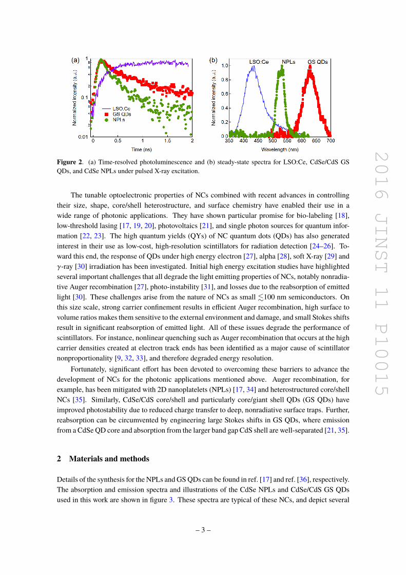
2016 JINST 11 P10015
372 nm laser
Streak Camera
LSO 2 mm
NPLs
a)
t (ns)
5
10
25
75
0 CdSe NPLsLSOCe λ (nm)b)
Figure 8 (a) Schematic view of the setup used to measure the heterostructure emission using laser and X-rayexcitation (b) NPLsLSOCe system under laser excitation
33 Nanocrystal and bulk scintillator heterostructures
Building up the thickness of NC films to fully stop high energy particles is challenging One solutionis to construct hybrid NC-bulk materials In this approach NCs can be used for the specialized taskof fast timing while the bulk scintillator provides stopping power and scintillation light for taskssuch as resolving particle energy Such a detector could be constructed from stacks of thin wafersof bulk scintillators with films of NCs coating their surfaces The design of this heterostructure forfast γ-ray tagging for example could be accomplished by making the dense bulk scintillator layerthinner than the recoil electron range allowing energy transfer to the nanocrystal thin film [39] Inthe following sections we investigate this concept by depositing CdSe NPL films and GS QD filmson the surfaces of LSOCe and LuAGCe respectively In this way photoluminescence comingfromNCs and conventional scintillators can be spectrally resolved in one streak image which allowsthe efficiency of the NCs to be estimated by comparing to known light yield values of the bulkscintillators A schematic view of the measurement can be seen in figure 8 together with a streakimage taken under laser excitation with the NPL heterostructure
331 CdSe NPLs deposited on LSOCe
A thin film of CdSe NPL was deposited on one of the large faces of a 2times6times8 mm3 LSOCe crystalX-rays directly excite the NPLs film and the energy that has not been deposited in the NCs thenreaches the scintillator along the 2 mm long axis Light imaged from a 500microm times 100 microm spot isshown in figure 9(a) where ultrafast CdSe NPL emission is seen between 505ndash550 nm spectrallyshifted from the LSOCe photoluminescence The sweeping range was set to 2 ns which allows usto resolve the first NPL decay component and directly compare to the intrinsic dynamics of NPLspresented in the previous section A long tail which follows the LSOCe decay time characteristicsis also present due to LSOCe blue light absorbed and re-emitted as green light from the CdSeNPLs However the majority of the CdSe NPL emission occurs during the LSOCe rise time
332 CdSeCdS GS QDs deposited on LuAGCe
A CdSeCdS GS QDs film was deposited on the large face of a 1times5times5mm3 LuAGCe crystal Thefilm was placed in front of the X-ray tube window and the sample was measured in transmission
ndash 9 ndash
2016 JINST 11 P10015
Figure 9 X-ray excitation of CdSe NPLs film deposited on a 2 times 6 times 8mm3 LSOCe scintillating crystal(a) Spectrally resolved streak image sweeping at 2 ns (b) Spectral integration of the streak image to yieldthe decay traces for LSOCe and CdSe NPLs The black line in (a) denotes the time-integrated profile
Figure 10 X-ray excitation of CdSeCdS GS QDs film deposited on 1times5times5 mm3 LuAGCe scintillatingcrystal (a) Spectrally resolved streak image sweeping at 5 ns (b) Timing performance of LuAGCe and GSQDs emission The black line in (a) denotes the time-integrated profile
mode through the 1 mm long axis Light was collected from a 500microm times 100 microm spot and bothscintillation (LuAGCe) and ultrafast (QDs) emission are produced which is shown in figure 10(a)There is a very fast QD component that occurs during the 500 ps rise time of the LuAGCescintillation and a long tail which can be due to either the slow component seen in CdSeCdS GSQDs [36] or absorption of LuAGCe light which is re-emitted with the typical LuAGCe decaycharacteristics
34 NCs light yield estimations
The light yield of the NC films under X-ray excitation can be estimated by comparing to the LSOCeand LuAGCe emission in figure 9(a) and figure 10(a) respectively Simulations using Geant4 [40]were used to determine the X-ray energy spectrum of the tungsten tube as well as the total energydeposited in the NC layer and scintillator after X-ray irradiation To demonstrate the effect of theNC film thickness simulations were run for thicknesses ranging from 100 nm to 100 microm In the
ndash 10 ndash
2016 JINST 11 P10015
simulations the NC films are declared using a filling factor of 50 to account for the presenceof organic surface ligands which decreases the overall density of the film The total number ofphotons emitted by the heterostructure is proportional to the energy deposited in each material andfollows the relation
LYNPLs =αNPLsY200ps
lowast LYLSO |t=15nsELSO
dep
ENPLsdep
(31)
LYQDs =αQDs
Y300pslowast LYLuAG |t=35ns
ELuAGdep
EQDsdep
(32)
Here α is the ratio between the total number of photons emitted by the NCs and the bulkscintillator This ratio is taken from the integrated time profile Since a rigorous calculation willhave to account for the amount of light reabsorbed and emitted by the NCs the estimations are doneby taking the number of photons emitted at early times of 0 to 200 ps for NPLs and 0 to 300 ps forGS QDs and normalizing to the total light yield with Y200ps = 061 and Y300ps = 023 respectivelyFor this correction the timing dynamics of the NCs on glass under X-ray excitation are used Therelative wavelength dependence of the streak photocathode quantum efficiency and the efficiency ofthe spectrograph grating are also taken into account Doing a background correction and comparingintegrals of blue and green light we calculate αNPLs = 01 for the green photons emitted between 0and 200 ps In the case of QDsLuAG αQDs = 1 for red photons emitted between 0 and 300 ps
Considering the LSO intrinsic light yield as 40 000 phMeV the amount of light emittedin the first 15 ns will be sim 1500 phMeV represented by the term LYLSO |t In the case of GSQDsLuAG we have taken an intrinsic light yield of 23 000 phMeV based on comparative lightyield measurements [7] Since LuAGCe has a second decay tail up to 1063 ns and the repetitionrate is 250 ns the LYLuAG |t for t lt 35 ns is approximately 500 phMeV This calculation considersa rise time of 535 ps and 2 decays components with different yields 44 70 ns and 56 1063 nstaken from [3]
The computed mean energy depositions are shown in figures 11(c) and 11(d) normalized tothe value obtained for a 100 microm thick film
Measuring the light yield for NC films under X-ray excitation is a challenging task and is partof ongoing work Some of the crucial requirements for this measurement are that the films musthave a constant thickness and a known packing density In the present work NC films were preparedby drop-casting from toluene solutions since this technique enables building up relatively thick filmswith sequential concentrated drops However the NC films prepared for this work had considerablevariation in thickness We estimated an average thickness on the order of 10 microm determined fromthe solution concentration volume deposited and film area This is a rough estimate and does notaccount for the variation in film thickness Using the average value of 10 microm we calculate lightyields of 2500 and 22000 photonsMeV for CdSe NPLs and CdSeCdS GS QDs respectively
4 Discussion
The lifetimes component yields and fraction of light emitted in the first 10 ps and 100 ps forCdSe NPLs and CdSeCdS GS QDs are summarized in table 1 where both the NPLs and GS QDs
ndash 11 ndash
2016 JINST 11 P10015
Edep (MeV)0 0005 001 0015 002 0025 003 0035 004 0045 005
1
10
210
310
ltEdepgt CdSe NPl --gt 02 keV
ltEdepgt LSO --gt 1405 keV
1 um film
Edep (MeV)0 0005 001 0015 002 0025 003 0035 004 0045 005
1
10
210
310
ltEdepgt GS QDs --gt 83 keV
ltEdepgt LuAG --gt 58 keV
100 um film
Thickness of QDs film
0 100 nm 1 um 10 um 100 um10
-3
10-2
10-1
100
101
CdSeCdS QDs
LuAGCe
ltEde
pgt (M
eV)
0 100 nm 1 um 10 um 100 um
ltE
de
pgt
(M
eV
)
10-3
10-2
10-1
100
101
LSO
CdSe NPls
Thickness of NPls film
a) b)
c)d)
Figure 11 NC light yield estimations under 40 keV X-ray excitation as a function of film thickness (a)Simulated spectrum of the energy deposited on NPLsLSO heteroestructure for each material when the filmthickness is 100 microm (b) Spectrum of the energy deposited on QDsLuAG heterostructure for each materialwhen the film thickness is 100 microm obtained by simulations c) and d) Values of mean energy deposited onNPLsLSO and QDsLuAG heterostructure for different film thickness
have components in the lower sub-ns region Under X-ray excitation these fast components havelarger relative amplitudes than under low-intensity laser excitation (see figure 5) The analysis donefor the red and blue shifted emission coming from GS QDs is done using the laser IRF due toincreased signal to noise in the narrower spectral slices Since the fit using the laser IRF is doneanalytically instead of by numerical methods it will introduce a better error estimation for lowsignal to noise data Apart from the normalized yields for each decay component an effectivelifetime τeff =
sumAi middot τi
sumAi is calculated for the different configurations using the amplitude of
each componentFor CdSe NPLs taking τeff = 520 ps from low intensity laser excitation and τeff = 77 ps from
X-ray excitation (table 1) the ratio of the slower laser excited emission to the faster X-ray excitedemission is 67 Considering that Auger recombination will typically lead to an order of magnitudeor higher lifetime shortening [41] this indicates that it may not play a significant role in the fastemission dynamics of CdSe NPLs under X-ray excitation
It is evident from the heterostructure results shown in figures 9 and 10 that an additional longerdecay component emerges due to absorption of the bulk scintillator light by the NC films This is
ndash 12 ndash
2016 JINST 11 P10015
t (ns)0 04 08 12 16 2
102
CdSe NPLsτd1 = 16 plusmn 3 ps τd2 = 301 plusmn 18 psτd3 = 40000 plusmn 39034 ps τr1 = 16 plusmn 3 ps
a)
x0 200 400 600 800 1000 1200 1400 1600 1800 20000
200
400
600
800
1000
1200
1400
τr1 = 0 plusmn 52 ps τr2 = 382 plusmn 59 ps
04 08 12 16 20
b)
t (ns)
LSOCe
Figure 12 (a) Timing performance of the NPLs film when deposited on top of LSOCe (b) Timingperformance of a conventional scintillator ie LSOCe in the first 15 ns
Table 1 Summary of the laser and X-ray excited photoluminescence lifetimes with corresponding integratedphoton yield fractions for NC thin films on glass substrates and on bulk scintillators The effective lifetimesτeff =
sumAi middot τi
sumAi were calculated using the respective amplitudes of each component The GS QD results
include lifetimes obtained for the slower red and faster blue sides of the spectrum integrated over the spectralranges shown in figure 7
laser IRF total IRFNCs Fits NCslaser
full NCsxminusraysfull Heterxminusrays
full
NPLs τ1 187 plusmn 910minus4 ps 24 plusmn 8 ps 16 plusmn 3 psY1 26 25 1τ2 1392 plusmn 110minus4ps 290 plusmn 11 ps 301 plusmn 18 psY2 74 75 2τeff 520 ps 77 ps mdash
Yield 10 ps 13 76 mdashYield 100 ps 15 44 mdash
NCs Fits NCsxminusraysred NCsxminusrays
blue NCsxminusraysfull Heterxminusrays
full
GS QDs τ1 445 plusmn 45 ps 281 plusmn 18 ps 263 plusmn 25 ps 12 psY1 18 100 25 03τ2 3490 plusmn 321 ps mdash 3301 plusmn 631 ps 763 plusmn 40 psY2 82 mdash 75 1τeff 1564 ps 281 ps 849 ps mdash
Yield 10 ps 07 35 08 mdashYield 100 ps 85 30 10 mdash
shown in figure 12 for CdSe NPLs where a long tail with a lifetime characteristic of the LSOCedecay time is present However the relative weights of the first and second decay componentsare preserved as shown in table 1 The third decay component is not shown since it followsthe 40 ns and 100 ns decays of LSOCe and LuAGCe respectively This indicates negligibleabsorptionre-emission at early times (0ndash300 ps) of the scintillating pulse Fitting the LSOCe
ndash 13 ndash
2016 JINST 11 P10015
rise time (figure 12(b)) the first two NPL decay components occur within the same timescaleas the direct and delayed excitation of the Ce3+ luminescent centers represented by τr1 and τr2respectively Similarly a long decay component following the LuAG emission lifetime appears forthe GS QDsLuAG heterostructure In both cases the secondary excitation by the bulk scintillatorand the intrinsic longer lifetime components of the NCs can be reduced by isolating the fast MXemission via spectral filtering This may serve as an important strategy when considering practicaldevices in which repeated layers of NCbulk scintillators are involved In such devices eliminatinglonger lifetime components will enable faster cycle times (or frame rates)
5 Conclusion and outlook
We have demonstrated that a new generation of colloidal nanocrystals hold significant potential asa material class to generate a prompt photo-response to ionizing particles NC radiative emissionlifetimes are shown to be significantly shorter than traditional scintillation mechanisms The CdSenanoplatelets and giant shell quantum dots studied here overcomemany of the challenges that earliergenerations of NCs faced under ionizing radiation Notably nonradiative Auger recombinationwhich also deteriorates bulk scintillator performance is suppressed in both systems Further thelarge shell of the CdSeCdS GS QDs overcomes several other challenges such as reabsorption ofemitted light by separating emission and absorption bands These features can in principle also beextended to NPLs via the growth of a larger bandgap shell such as CdS or ZnS
Future studies of the ultrafast processes presented here will be aided by parallel efforts to lowerthe time resolution of the streak camera system when using X-ray excitation The signal to noiseratio constitutes a major limitation which can be overcome by increasing the X-ray flux in a 100 micromspot by means of a poly-capillary X-rays lens The determination of the presently unresolved decaycomponents for NPLs and QDs could bring deeper insight to faster regimes for light emission underionizing radiation Additionally better determination of the NCs photon yield can be accomplishedby using spin coating or an equivalent process of depositing uniform films of controllable thickness
We have shown that colloidal nanocrystal-based scintillators are a promising approach to fasttiming and provide a feasible path toward sub-20 ps time resolution Future lines of research willbe directed toward NCs embedded in a host matrix as proposed in ref [26] in order to increase thestopping power and the energy transfer efficiency
Acknowledgments
This work was carried out in the frame of the ERC Advanced Grant TICAL 338953 (PI PaulLecoq) and the Crystal Clear collaboration It was also supported by a Marie Curie Early InitialTraining Network Fellowship of the European Communityrsquos 7th Framework Programme undercontract number (PITN-GA-2011-289355-PicoSEC-MCNet) and the COST Action Fast TD1401
References
[1] CWE van Eijk Inorganic scintillators in medical imaging Phys Med Biol 47 (2002) R85
ndash 14 ndash
2016 JINST 11 P10015
[2] P Lecoq Development of new scintillators for medical applications Nucl Instrum Meth A 809(2016) 130
[3] S Gundacker E Auffray K Pauwels and P LecoqMeasurement of intrinsic rise times for variousl(y)so and luag scintillators with a general study of prompt photons to achieve 10 ps in tof-pet PhysMed Biol 61 (2016) 280
[4] D del Re Timing performance of the cms ecal and prospects for the future J Phys Conf Ser 587(2015) 012003
[5] S Gundacker et al Time of flight positron emission tomography towards 100 ps resolution withl(y)so an experimental and theoretical analysis 2013 JINST 8 P07014
[6] E Auffray et al Characterization studies of silicon photomultipliers and crystals matrices for a noveltime of flight pet detector 2015 JINST 10 P06009
[7] S Gundacker and et al State-of-the-art timing in tof-pet detectors with luag gagg and l(y)soscintillators of various sites coupled to fbk-sipms 2016 JINST 11 P08008
[8] RM Turtos et alMeasurement of lyso intrinsic light yield using electron excitation IEEE TransNucl Sci 63 (2016) 475
[9] P Dorenbos Fundamental limitations in the performance of Ce3+ Pr3+ and Eu2+ activatedscintillators IEEE Trans Nucl Sci 57 (2010) 1162
[10] SE Brunner L Gruber J Marton K Suzuki and A Hirtl Studies on the cherenkov effect forimproved time resolution of tof-pet IEEE Trans Nucl Sci 61 (2014) 443
[11] S Korpar R Dolenec P Križan R Pestotnik and A Stanovnik Study of tof-pet using cherenkovlight Phys Proc 37 (2012) 1531
[12] P Lecoq et al Factors influencing time resolution of scintillators and ways to improve them IEEETrans Nucl Sci 57 (2010) 2411
[13] S Omelkov V Nagirnyi A Vasilrsquoev and M Kirm New features of hot intraband luminescence forfast timing J Luminesc 176 (2016) 309
[14] P Lecoq M Korzhik and A Vasilrsquoev Can transient phenomena help improving time resolution inscintillators IEEE Trans Nucl Sci 61 (2014) 229
[15] S Ithurria et al Colloidal nanoplatelets with two-dimensional electronic structure Nature Mat 10(2011) 936
[16] A Naeem F Masia S Christodoulou I Moreels P Borri and W Langbein Giant exciton oscillatorstrength and radiatively limited dephasing in two-dimensional platelets Phys Rev B 91 (2015)121302
[17] JQ Grim et al Continuous-wave biexciton lasing at room temperature using solution-processedquantum wells Nature Nanotechnol 9 (2014) 891
[18] D Deng et al High-quality CuInS2-ZnS quantum dots for in vitro and in vivo bioimaging ChemMater 24 (2012) 3029
[19] B Guzelturk Y Kelestemur M Olutas S Delikanli and HV Demir Amplified spontaneousemission and lasing in colloidal nanoplatelets ACS Nano 8 (2014) 6599
[20] VI Klimov et al Optical gain and stimulated emission in nanocrystal quantum dots Science 290(2000) 314
[21] F Meinardi et al Large-area luminescent solar concentrators based on stokes-shift-engineerednanocrystals in a mass-polymerized pmma matrix Nature Phot 8 (2014) 392
ndash 15 ndash
2016 JINST 11 P10015
[22] F Pisanello et al Room temperature-dipolelike single photon source with a colloidal dot-in-rodAppl Phys Lett 96 (2010) 033101
[23] MAM Versteegh et al Observation of strongly entangled photon pairs from a nanowire quantumdot Nature Commun 5 (2014) 5298
[24] L Prochaacutezkovaacute T Gbur V Čuba V Jaryacute and M Nikl Fabrication of highly efficient ZnOnanoscintillators Opt Mater 47 (2015) 67
[25] C Liu T J Hajagos D Kishpaugh Y Jin W Hu Q Chen et al Facile single-precursor synthesisand surface modification of hafnium oxide nanoparticles for nanocomposite γ-ray scintillators AdvFunct Mater 25 (2015) 4607
[26] H Burešovaacute et al Preparation and luminescence properties of znoga polystyrene compositescintillator Opt Express 24 (2016) 15289
[27] L A Padilha W K Bae V I Klimov J M Pietryga and R D Schaller Response of semiconductornanocrystals to extremely energetic excitation Nano Lett 13 (2013) 925
[28] S Leacutetant and T Wang Study of porous glass doped with quantum dots or laser dyes under alphairradiation Appl Phys Lett 88 (2005) 103110
[29] P Brůža et al Applications of a table-top time-resolved luminescence spectrometer with nanosecondsoft x-ray pulse excitation IEEE Trans Nucl Sci 61 (2014) 448
[30] SE Leacutetant and T Wang Semiconductor quantum dot scintillation under γ-ray irradiation NanoLett 6 (2006) 2877
[31] NJ Withers et al Rapid degradation of cdse-zns colloidal quantum dots exposed to gammairradiation Appl Phys Lett 93 (2008) 173101
[32] RT Williams et al Excitation density diffusion-drift and proportionality in scintillators Phys StatSol B 248 (2011) 426
[33] JQ Grim et al Nonlinear quenching of densely excited states in wide-gap solids Phys Rev B 87(2013) 125117
[34] LT Kunneman et al Bimolecular auger recombination of electron-hole pairs in two-dimensionalcdse and cdsecdzns coreshell nanoplatelets J Phys Chem Lett 4 (2013) 3574
[35] FG Santamariacutea et al Suppressed auger recombination in giant nanocrystals boosts optical gainperformance Nano Lett 9 (2009) 3482
[36] S Christodoulou et al Synthesis of highly luminescent wurtzite cdsecds giant-shell nanocrystalsusing a fast continuous injection route J Mater Chem C 2 (2014) 3439
[37] G Rainograve et al Exciton dynamics within the band-edge manifold states the onset of an acousticphonon bottleneck Nano Lett 12 (2012) 5224
[38] H Htoon et al Highly emissive multiexcitons in steady-state photoluminescence of individual giantcdsecds core-shell nanocrystals Nano Lett 10 (2010) 2401
[39] P Lecoq Metamaterials for novel x- or gamma-ray detector designs IEEE Nucl Sci Symp ConfRec 07-1 (2008) 680
[40] S Agostinelli and et al GEANT4 mdash A simulation toolkit Nucl Instrum Meth A 506 (2003) 250
[41] C Dang et al Red green and blue lasing enabled by single-exciton gain in colloidal quantum dotfilms Nature Nanotechol 7 (2012) 335
ndash 16 ndash
- Introduction
- Materials and methods
- Results
-
- Laser excitation of NC thin films
- X-ray excitation of NC thin films
-
- CdSe nanoplatelets
- CdSeCdS giant shell quantum dots
-
- Nanocrystal and bulk scintillator heterostructures
-
- CdSe NPLs deposited on LSOCe
- CdSeCdS GS QDs deposited on LuAGCe
-
- NCs light yield estimations
-
- Discussion
- Conclusion and outlook
-
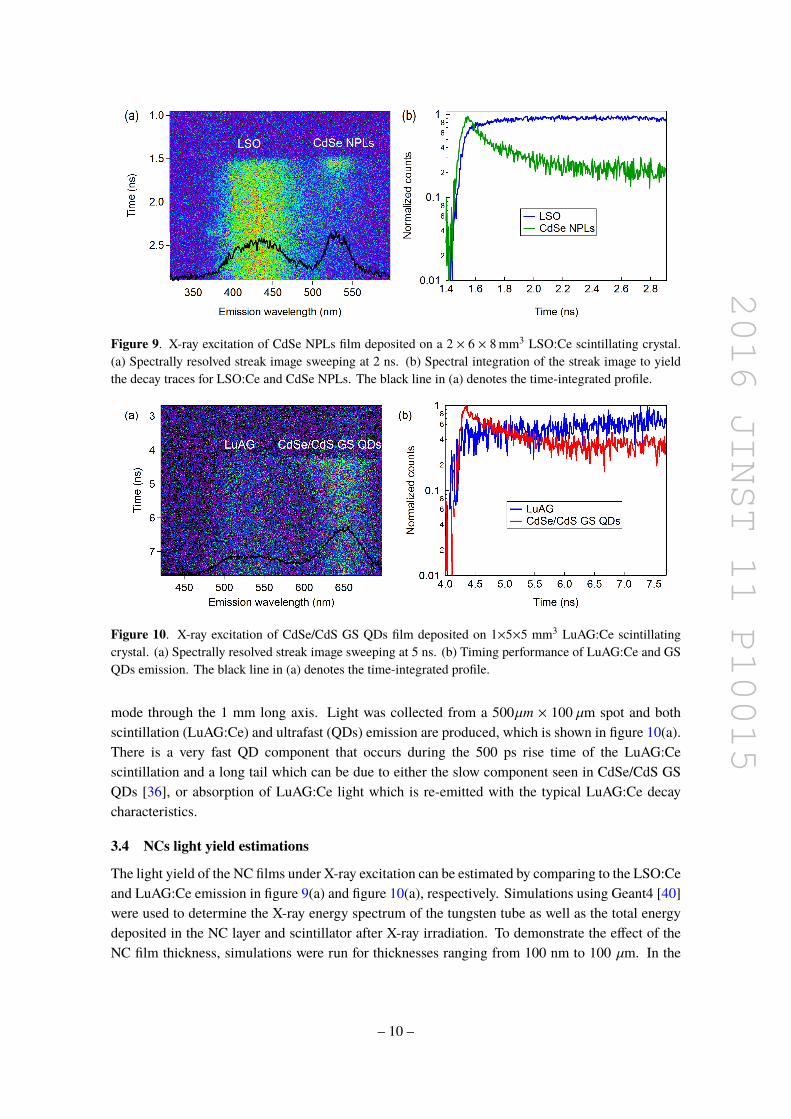
2016 JINST 11 P10015
Edep (MeV)0 0005 001 0015 002 0025 003 0035 004 0045 005
1
10
210
310
ltEdepgt CdSe NPl --gt 02 keV
ltEdepgt LSO --gt 1405 keV
1 um film
Edep (MeV)0 0005 001 0015 002 0025 003 0035 004 0045 005
1
10
210
310
ltEdepgt GS QDs --gt 83 keV
ltEdepgt LuAG --gt 58 keV
100 um film
Thickness of QDs film
0 100 nm 1 um 10 um 100 um10
-3
10-2
10-1
100
101
CdSeCdS QDs
LuAGCe
ltEde
pgt (M
eV)
0 100 nm 1 um 10 um 100 um
ltE
de
pgt
(M
eV
)
10-3
10-2
10-1
100
101
LSO
CdSe NPls
Thickness of NPls film
a) b)
c)d)
Figure 11 NC light yield estimations under 40 keV X-ray excitation as a function of film thickness (a)Simulated spectrum of the energy deposited on NPLsLSO heteroestructure for each material when the filmthickness is 100 microm (b) Spectrum of the energy deposited on QDsLuAG heterostructure for each materialwhen the film thickness is 100 microm obtained by simulations c) and d) Values of mean energy deposited onNPLsLSO and QDsLuAG heterostructure for different film thickness
have components in the lower sub-ns region Under X-ray excitation these fast components havelarger relative amplitudes than under low-intensity laser excitation (see figure 5) The analysis donefor the red and blue shifted emission coming from GS QDs is done using the laser IRF due toincreased signal to noise in the narrower spectral slices Since the fit using the laser IRF is doneanalytically instead of by numerical methods it will introduce a better error estimation for lowsignal to noise data Apart from the normalized yields for each decay component an effectivelifetime τeff =
sumAi middot τi
sumAi is calculated for the different configurations using the amplitude of
each componentFor CdSe NPLs taking τeff = 520 ps from low intensity laser excitation and τeff = 77 ps from
X-ray excitation (table 1) the ratio of the slower laser excited emission to the faster X-ray excitedemission is 67 Considering that Auger recombination will typically lead to an order of magnitudeor higher lifetime shortening [41] this indicates that it may not play a significant role in the fastemission dynamics of CdSe NPLs under X-ray excitation
It is evident from the heterostructure results shown in figures 9 and 10 that an additional longerdecay component emerges due to absorption of the bulk scintillator light by the NC films This is
ndash 12 ndash
2016 JINST 11 P10015
t (ns)0 04 08 12 16 2
102
CdSe NPLsτd1 = 16 plusmn 3 ps τd2 = 301 plusmn 18 psτd3 = 40000 plusmn 39034 ps τr1 = 16 plusmn 3 ps
a)
x0 200 400 600 800 1000 1200 1400 1600 1800 20000
200
400
600
800
1000
1200
1400
τr1 = 0 plusmn 52 ps τr2 = 382 plusmn 59 ps
04 08 12 16 20
b)
t (ns)
LSOCe
Figure 12 (a) Timing performance of the NPLs film when deposited on top of LSOCe (b) Timingperformance of a conventional scintillator ie LSOCe in the first 15 ns
Table 1 Summary of the laser and X-ray excited photoluminescence lifetimes with corresponding integratedphoton yield fractions for NC thin films on glass substrates and on bulk scintillators The effective lifetimesτeff =
sumAi middot τi
sumAi were calculated using the respective amplitudes of each component The GS QD results
include lifetimes obtained for the slower red and faster blue sides of the spectrum integrated over the spectralranges shown in figure 7
laser IRF total IRFNCs Fits NCslaser
full NCsxminusraysfull Heterxminusrays
full
NPLs τ1 187 plusmn 910minus4 ps 24 plusmn 8 ps 16 plusmn 3 psY1 26 25 1τ2 1392 plusmn 110minus4ps 290 plusmn 11 ps 301 plusmn 18 psY2 74 75 2τeff 520 ps 77 ps mdash
Yield 10 ps 13 76 mdashYield 100 ps 15 44 mdash
NCs Fits NCsxminusraysred NCsxminusrays
blue NCsxminusraysfull Heterxminusrays
full
GS QDs τ1 445 plusmn 45 ps 281 plusmn 18 ps 263 plusmn 25 ps 12 psY1 18 100 25 03τ2 3490 plusmn 321 ps mdash 3301 plusmn 631 ps 763 plusmn 40 psY2 82 mdash 75 1τeff 1564 ps 281 ps 849 ps mdash
Yield 10 ps 07 35 08 mdashYield 100 ps 85 30 10 mdash
shown in figure 12 for CdSe NPLs where a long tail with a lifetime characteristic of the LSOCedecay time is present However the relative weights of the first and second decay componentsare preserved as shown in table 1 The third decay component is not shown since it followsthe 40 ns and 100 ns decays of LSOCe and LuAGCe respectively This indicates negligibleabsorptionre-emission at early times (0ndash300 ps) of the scintillating pulse Fitting the LSOCe
ndash 13 ndash
2016 JINST 11 P10015
rise time (figure 12(b)) the first two NPL decay components occur within the same timescaleas the direct and delayed excitation of the Ce3+ luminescent centers represented by τr1 and τr2respectively Similarly a long decay component following the LuAG emission lifetime appears forthe GS QDsLuAG heterostructure In both cases the secondary excitation by the bulk scintillatorand the intrinsic longer lifetime components of the NCs can be reduced by isolating the fast MXemission via spectral filtering This may serve as an important strategy when considering practicaldevices in which repeated layers of NCbulk scintillators are involved In such devices eliminatinglonger lifetime components will enable faster cycle times (or frame rates)
5 Conclusion and outlook
We have demonstrated that a new generation of colloidal nanocrystals hold significant potential asa material class to generate a prompt photo-response to ionizing particles NC radiative emissionlifetimes are shown to be significantly shorter than traditional scintillation mechanisms The CdSenanoplatelets and giant shell quantum dots studied here overcomemany of the challenges that earliergenerations of NCs faced under ionizing radiation Notably nonradiative Auger recombinationwhich also deteriorates bulk scintillator performance is suppressed in both systems Further thelarge shell of the CdSeCdS GS QDs overcomes several other challenges such as reabsorption ofemitted light by separating emission and absorption bands These features can in principle also beextended to NPLs via the growth of a larger bandgap shell such as CdS or ZnS
Future studies of the ultrafast processes presented here will be aided by parallel efforts to lowerthe time resolution of the streak camera system when using X-ray excitation The signal to noiseratio constitutes a major limitation which can be overcome by increasing the X-ray flux in a 100 micromspot by means of a poly-capillary X-rays lens The determination of the presently unresolved decaycomponents for NPLs and QDs could bring deeper insight to faster regimes for light emission underionizing radiation Additionally better determination of the NCs photon yield can be accomplishedby using spin coating or an equivalent process of depositing uniform films of controllable thickness
We have shown that colloidal nanocrystal-based scintillators are a promising approach to fasttiming and provide a feasible path toward sub-20 ps time resolution Future lines of research willbe directed toward NCs embedded in a host matrix as proposed in ref [26] in order to increase thestopping power and the energy transfer efficiency
Acknowledgments
This work was carried out in the frame of the ERC Advanced Grant TICAL 338953 (PI PaulLecoq) and the Crystal Clear collaboration It was also supported by a Marie Curie Early InitialTraining Network Fellowship of the European Communityrsquos 7th Framework Programme undercontract number (PITN-GA-2011-289355-PicoSEC-MCNet) and the COST Action Fast TD1401
References
[1] CWE van Eijk Inorganic scintillators in medical imaging Phys Med Biol 47 (2002) R85
ndash 14 ndash
2016 JINST 11 P10015
[2] P Lecoq Development of new scintillators for medical applications Nucl Instrum Meth A 809(2016) 130
[3] S Gundacker E Auffray K Pauwels and P LecoqMeasurement of intrinsic rise times for variousl(y)so and luag scintillators with a general study of prompt photons to achieve 10 ps in tof-pet PhysMed Biol 61 (2016) 280
[4] D del Re Timing performance of the cms ecal and prospects for the future J Phys Conf Ser 587(2015) 012003
[5] S Gundacker et al Time of flight positron emission tomography towards 100 ps resolution withl(y)so an experimental and theoretical analysis 2013 JINST 8 P07014
[6] E Auffray et al Characterization studies of silicon photomultipliers and crystals matrices for a noveltime of flight pet detector 2015 JINST 10 P06009
[7] S Gundacker and et al State-of-the-art timing in tof-pet detectors with luag gagg and l(y)soscintillators of various sites coupled to fbk-sipms 2016 JINST 11 P08008
[8] RM Turtos et alMeasurement of lyso intrinsic light yield using electron excitation IEEE TransNucl Sci 63 (2016) 475
[9] P Dorenbos Fundamental limitations in the performance of Ce3+ Pr3+ and Eu2+ activatedscintillators IEEE Trans Nucl Sci 57 (2010) 1162
[10] SE Brunner L Gruber J Marton K Suzuki and A Hirtl Studies on the cherenkov effect forimproved time resolution of tof-pet IEEE Trans Nucl Sci 61 (2014) 443
[11] S Korpar R Dolenec P Križan R Pestotnik and A Stanovnik Study of tof-pet using cherenkovlight Phys Proc 37 (2012) 1531
[12] P Lecoq et al Factors influencing time resolution of scintillators and ways to improve them IEEETrans Nucl Sci 57 (2010) 2411
[13] S Omelkov V Nagirnyi A Vasilrsquoev and M Kirm New features of hot intraband luminescence forfast timing J Luminesc 176 (2016) 309
[14] P Lecoq M Korzhik and A Vasilrsquoev Can transient phenomena help improving time resolution inscintillators IEEE Trans Nucl Sci 61 (2014) 229
[15] S Ithurria et al Colloidal nanoplatelets with two-dimensional electronic structure Nature Mat 10(2011) 936
[16] A Naeem F Masia S Christodoulou I Moreels P Borri and W Langbein Giant exciton oscillatorstrength and radiatively limited dephasing in two-dimensional platelets Phys Rev B 91 (2015)121302
[17] JQ Grim et al Continuous-wave biexciton lasing at room temperature using solution-processedquantum wells Nature Nanotechnol 9 (2014) 891
[18] D Deng et al High-quality CuInS2-ZnS quantum dots for in vitro and in vivo bioimaging ChemMater 24 (2012) 3029
[19] B Guzelturk Y Kelestemur M Olutas S Delikanli and HV Demir Amplified spontaneousemission and lasing in colloidal nanoplatelets ACS Nano 8 (2014) 6599
[20] VI Klimov et al Optical gain and stimulated emission in nanocrystal quantum dots Science 290(2000) 314
[21] F Meinardi et al Large-area luminescent solar concentrators based on stokes-shift-engineerednanocrystals in a mass-polymerized pmma matrix Nature Phot 8 (2014) 392
ndash 15 ndash
2016 JINST 11 P10015
[22] F Pisanello et al Room temperature-dipolelike single photon source with a colloidal dot-in-rodAppl Phys Lett 96 (2010) 033101
[23] MAM Versteegh et al Observation of strongly entangled photon pairs from a nanowire quantumdot Nature Commun 5 (2014) 5298
[24] L Prochaacutezkovaacute T Gbur V Čuba V Jaryacute and M Nikl Fabrication of highly efficient ZnOnanoscintillators Opt Mater 47 (2015) 67
[25] C Liu T J Hajagos D Kishpaugh Y Jin W Hu Q Chen et al Facile single-precursor synthesisand surface modification of hafnium oxide nanoparticles for nanocomposite γ-ray scintillators AdvFunct Mater 25 (2015) 4607
[26] H Burešovaacute et al Preparation and luminescence properties of znoga polystyrene compositescintillator Opt Express 24 (2016) 15289
[27] L A Padilha W K Bae V I Klimov J M Pietryga and R D Schaller Response of semiconductornanocrystals to extremely energetic excitation Nano Lett 13 (2013) 925
[28] S Leacutetant and T Wang Study of porous glass doped with quantum dots or laser dyes under alphairradiation Appl Phys Lett 88 (2005) 103110
[29] P Brůža et al Applications of a table-top time-resolved luminescence spectrometer with nanosecondsoft x-ray pulse excitation IEEE Trans Nucl Sci 61 (2014) 448
[30] SE Leacutetant and T Wang Semiconductor quantum dot scintillation under γ-ray irradiation NanoLett 6 (2006) 2877
[31] NJ Withers et al Rapid degradation of cdse-zns colloidal quantum dots exposed to gammairradiation Appl Phys Lett 93 (2008) 173101
[32] RT Williams et al Excitation density diffusion-drift and proportionality in scintillators Phys StatSol B 248 (2011) 426
[33] JQ Grim et al Nonlinear quenching of densely excited states in wide-gap solids Phys Rev B 87(2013) 125117
[34] LT Kunneman et al Bimolecular auger recombination of electron-hole pairs in two-dimensionalcdse and cdsecdzns coreshell nanoplatelets J Phys Chem Lett 4 (2013) 3574
[35] FG Santamariacutea et al Suppressed auger recombination in giant nanocrystals boosts optical gainperformance Nano Lett 9 (2009) 3482
[36] S Christodoulou et al Synthesis of highly luminescent wurtzite cdsecds giant-shell nanocrystalsusing a fast continuous injection route J Mater Chem C 2 (2014) 3439
[37] G Rainograve et al Exciton dynamics within the band-edge manifold states the onset of an acousticphonon bottleneck Nano Lett 12 (2012) 5224
[38] H Htoon et al Highly emissive multiexcitons in steady-state photoluminescence of individual giantcdsecds core-shell nanocrystals Nano Lett 10 (2010) 2401
[39] P Lecoq Metamaterials for novel x- or gamma-ray detector designs IEEE Nucl Sci Symp ConfRec 07-1 (2008) 680
[40] S Agostinelli and et al GEANT4 mdash A simulation toolkit Nucl Instrum Meth A 506 (2003) 250
[41] C Dang et al Red green and blue lasing enabled by single-exciton gain in colloidal quantum dotfilms Nature Nanotechol 7 (2012) 335
ndash 16 ndash
- Introduction
- Materials and methods
- Results
-
- Laser excitation of NC thin films
- X-ray excitation of NC thin films
-
- CdSe nanoplatelets
- CdSeCdS giant shell quantum dots
-
- Nanocrystal and bulk scintillator heterostructures
-
- CdSe NPLs deposited on LSOCe
- CdSeCdS GS QDs deposited on LuAGCe
-
- NCs light yield estimations
-
- Discussion
- Conclusion and outlook
-

2016 JINST 11 P10015
[22] F Pisanello et al Room temperature-dipolelike single photon source with a colloidal dot-in-rodAppl Phys Lett 96 (2010) 033101
[23] MAM Versteegh et al Observation of strongly entangled photon pairs from a nanowire quantumdot Nature Commun 5 (2014) 5298
[24] L Prochaacutezkovaacute T Gbur V Čuba V Jaryacute and M Nikl Fabrication of highly efficient ZnOnanoscintillators Opt Mater 47 (2015) 67
[25] C Liu T J Hajagos D Kishpaugh Y Jin W Hu Q Chen et al Facile single-precursor synthesisand surface modification of hafnium oxide nanoparticles for nanocomposite γ-ray scintillators AdvFunct Mater 25 (2015) 4607
[26] H Burešovaacute et al Preparation and luminescence properties of znoga polystyrene compositescintillator Opt Express 24 (2016) 15289
[27] L A Padilha W K Bae V I Klimov J M Pietryga and R D Schaller Response of semiconductornanocrystals to extremely energetic excitation Nano Lett 13 (2013) 925
[28] S Leacutetant and T Wang Study of porous glass doped with quantum dots or laser dyes under alphairradiation Appl Phys Lett 88 (2005) 103110
[29] P Brůža et al Applications of a table-top time-resolved luminescence spectrometer with nanosecondsoft x-ray pulse excitation IEEE Trans Nucl Sci 61 (2014) 448
[30] SE Leacutetant and T Wang Semiconductor quantum dot scintillation under γ-ray irradiation NanoLett 6 (2006) 2877
[31] NJ Withers et al Rapid degradation of cdse-zns colloidal quantum dots exposed to gammairradiation Appl Phys Lett 93 (2008) 173101
[32] RT Williams et al Excitation density diffusion-drift and proportionality in scintillators Phys StatSol B 248 (2011) 426
[33] JQ Grim et al Nonlinear quenching of densely excited states in wide-gap solids Phys Rev B 87(2013) 125117
[34] LT Kunneman et al Bimolecular auger recombination of electron-hole pairs in two-dimensionalcdse and cdsecdzns coreshell nanoplatelets J Phys Chem Lett 4 (2013) 3574
[35] FG Santamariacutea et al Suppressed auger recombination in giant nanocrystals boosts optical gainperformance Nano Lett 9 (2009) 3482
[36] S Christodoulou et al Synthesis of highly luminescent wurtzite cdsecds giant-shell nanocrystalsusing a fast continuous injection route J Mater Chem C 2 (2014) 3439
[37] G Rainograve et al Exciton dynamics within the band-edge manifold states the onset of an acousticphonon bottleneck Nano Lett 12 (2012) 5224
[38] H Htoon et al Highly emissive multiexcitons in steady-state photoluminescence of individual giantcdsecds core-shell nanocrystals Nano Lett 10 (2010) 2401
[39] P Lecoq Metamaterials for novel x- or gamma-ray detector designs IEEE Nucl Sci Symp ConfRec 07-1 (2008) 680
[40] S Agostinelli and et al GEANT4 mdash A simulation toolkit Nucl Instrum Meth A 506 (2003) 250
[41] C Dang et al Red green and blue lasing enabled by single-exciton gain in colloidal quantum dotfilms Nature Nanotechol 7 (2012) 335
ndash 16 ndash
- Introduction
- Materials and methods
- Results
-
- Laser excitation of NC thin films
- X-ray excitation of NC thin films
-
- CdSe nanoplatelets
- CdSeCdS giant shell quantum dots
-
- Nanocrystal and bulk scintillator heterostructures
-
- CdSe NPLs deposited on LSOCe
- CdSeCdS GS QDs deposited on LuAGCe
-
- NCs light yield estimations
-
- Discussion
- Conclusion and outlook
-
Related Documents