presented by: Jan Sjögren Ultra Wide Band Measurements & Testing Ultra Wide Band Measurements & Testing September 2004 • What does “UWB” mean • UWB Engineering Challenges • Design Simulation and Integration • Transmitter Measurements –Pulsed Baseband & DS-UWB –MB-OFDM • Interference and Receiver Measurements • Differential Measurements Agenda

Welcome message from author
This document is posted to help you gain knowledge. Please leave a comment to let me know what you think about it! Share it to your friends and learn new things together.
Transcript
��
presented by:
Jan Sjögren
Ultra Wide Band Measurements & Testing
Ultra Wide Band Measurements & Testing
September 2004
• What does “UWB” mean• UWB Engineering Challenges• Design Simulation and Integration• Transmitter Measurements
–Pulsed Baseband & DS-UWB–MB-OFDM
• Interference and Receiver Measurements• Differential Measurements
Agenda
��
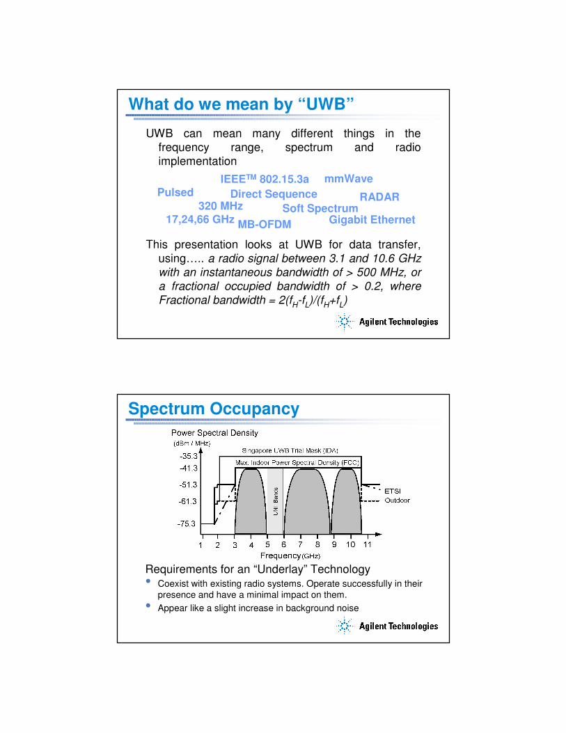
What do we mean by “UWB”
UWB can mean many different things in the frequency range, spectrum and radio implementation
This presentation looks at UWB for data transfer, using….. a radio signal between 3.1 and 10.6 GHz with an instantaneous bandwidth of > 500 MHz, or a fractional occupied bandwidth of > 0.2, where Fractional bandwidth = 2(fH-fL)/(fH+fL)
Pulsed Direct SequencemmWave
Gigabit Ethernet17,24,66 GHz320 MHz
MB-OFDM
IEEETM 802.15.3a
RADARSoft Spectrum
Spectrum Occupancy
Requirements for an “Underlay” Technology• Coexist with existing radio systems. Operate successfully in their
presence and have a minimal impact on them. • Appear like a slight increase in background noise
��
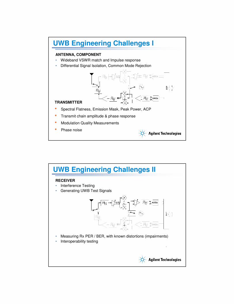
UWB Engineering Challenges IANTENNA, COMPONENT• Wideband VSWR match and Impulse response• Differential Signal Isolation, Common Mode Rejection
TRANSMITTER
• Spectral Flatness, Emission Mask, Peak Power, ACP
• Transmit chain amplitude & phase response
• Modulation Quality Measurements
• Phase noise
UWB Engineering Challenges IIRECEIVER• Interference Testing• Generating UWB Test Signals
• Measuring Rx PER / BER, with known distortions (impairments)• Interoperability testing
��
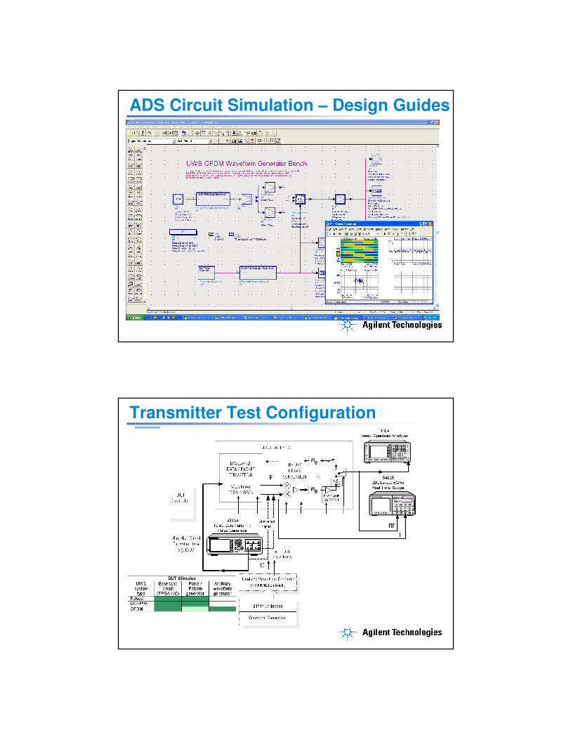
ADS Circuit Simulation – Design Guides
Transmitter Test Configuration
��
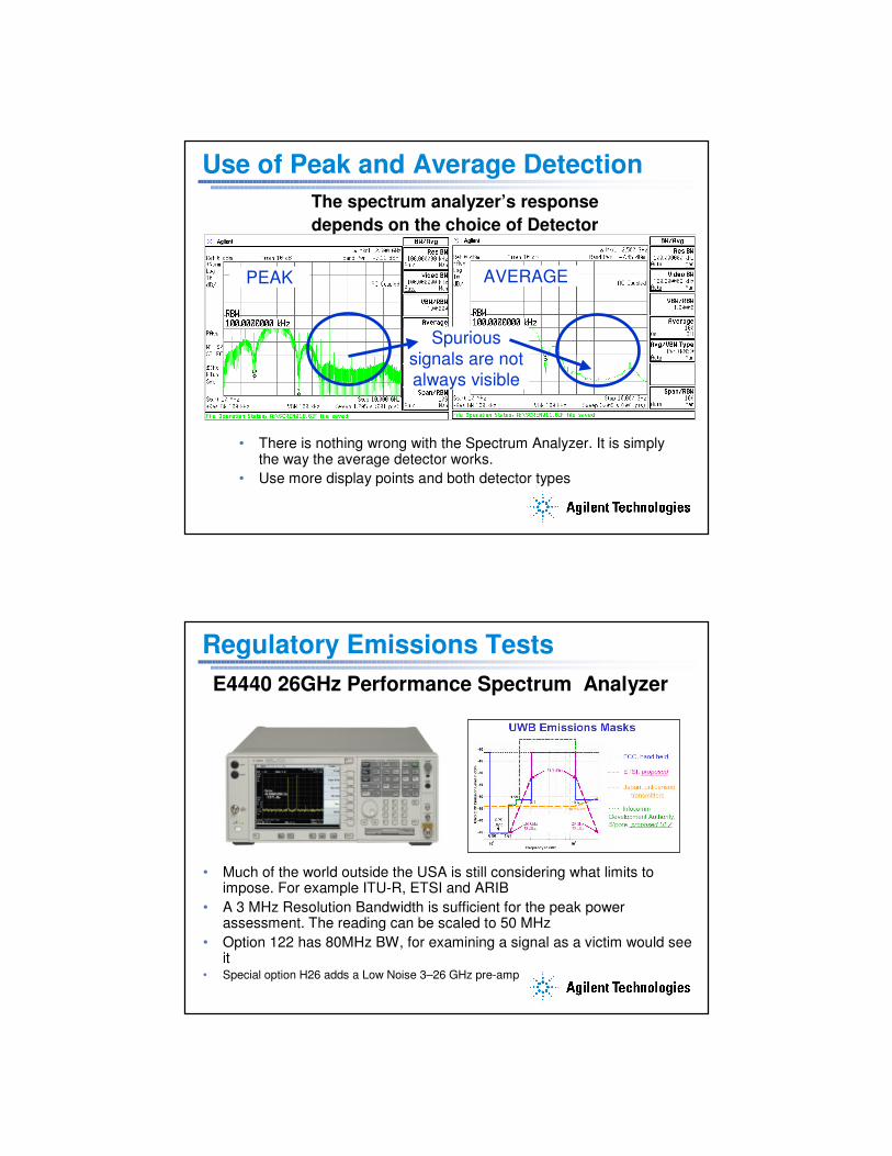
Use of Peak and Average DetectionThe spectrum analyzer’s responsedepends on the choice of Detector
Spurious signals are not always visible
PEAK AVERAGE
• There is nothing wrong with the Spectrum Analyzer. It is simply the way the average detector works.
• Use more display points and both detector types
Regulatory Emissions TestsE4440 26GHz Performance Spectrum Analyzer
• Much of the world outside the USA is still considering what limits to impose. For example ITU-R, ETSI and ARIB
• A 3 MHz Resolution Bandwidth is sufficient for the peak power assessment. The reading can be scaled to 50 MHz
• Option 122 has 80MHz BW, for examining a signal as a victim would see it
• Special option H26 adds a Low Noise 3–26 GHz pre-amp
��
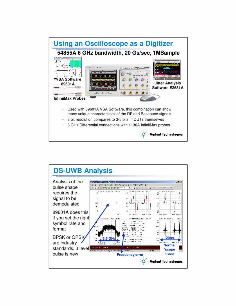
Using an Oscilloscope as a Digitizer
• Used with 89601A VSA Software, this combination can show many unique characteristics of the RF and Baseband signals
• 8 bit resolution compares to 3-5 bits in DUTs themselves• 6 GHz Differential connections with 1130A InfiniiMax probes
54855A 6 GHz bandwidth, 20 Gs/sec, 1MSample
InfiniiMax Probes
VSA Software 89601A Jitter Analysis
Software E2681A
DS-UWB AnalysisAnalysis of the pulse shape requires the signal to be demodulated
89601A does this if you set the right symbol rate and format
BPSK or QPSK are industry standards. 3 level pulse is new!
Normal ‘scope traceFrequency error
20ns3.5 GHz
��
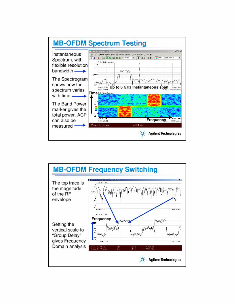
MB-OFDM Spectrum TestingInstantaneous Spectrum, with flexible resolution bandwidth
The Spectrogram shows how the spectrum varies with time
The Band Power marker gives the total power. ACP can also be measured
Up to 6 GHz instantaneous span
Frequency
Time
MB-OFDM Frequency Switching
The top trace is the magnitude of the RF envelope
Setting the vertical scale to “Group Delay” gives Frequency Domain analysis
Frequency
�
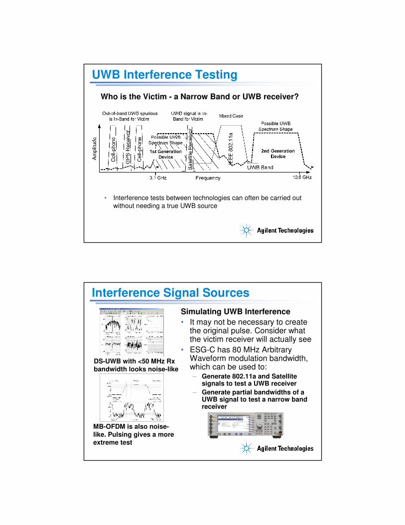
UWB Interference Testing
Who is the Victim - a Narrow Band or UWB receiver?
• Interference tests between technologies can often be carried outwithout needing a true UWB source
Interference Signal SourcesSimulating UWB Interference• It may not be necessary to create
the original pulse. Consider what the victim receiver will actually see
• ESG-C has 80 MHz Arbitrary Waveform modulation bandwidth, which can be used to:– Generate 802.11a and Satellite
signals to test a UWB receiver– Generate partial bandwidths of a
UWB signal to test a narrow band receiver
DS-UWB with <50 MHz Rx bandwidth looks noise-like
MB-OFDM is also noise-like. Pulsing gives a more extreme test
�
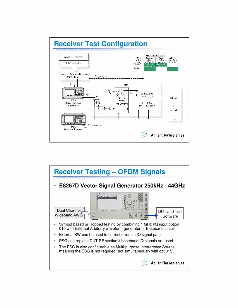
Receiver Test Configuration
Receiver Testing – OFDM Signals
• E8267D Vector Signal Generator 250kHz - 44GHz
• Symbol based or Hopped testing by combining 1 GHz I/Q input option 015 with External Arbitrary waveform generator or Baseband circuit
• External SW can be used to correct errors in IQ signal path
• PSG can replace DUT RF section if baseband IQ signals are used
• The PSG is also configurable as Multi-purpose Interference Source, meaning the ESG is not required (not simultaneously with opt 015)
Dual Channel Wideband AWG
DUT and Test Software
���
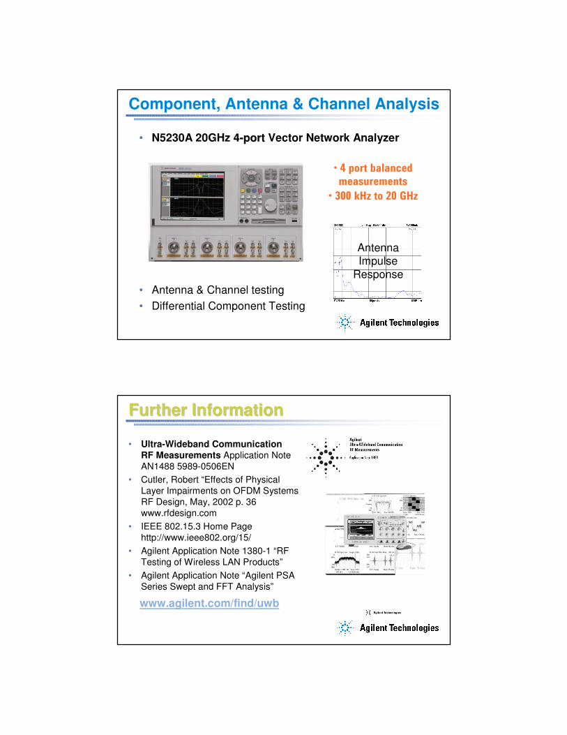
Component, Antenna & Channel Analysis
• N5230A 20GHz 44--portport Vector Network Analyzer
• Antenna & Channel testing • Differential Component Testing
Antenna Impulse
Response
� ������������ ��������
�����������
� �����������������
Further InformationFurther Information
www.agilent.com/find/uwb
• Ultra-Wideband Communication RF Measurements Application Note AN1488 5989-0506EN
• Cutler, Robert “Effects of Physical Layer Impairments on OFDM Systems” RF Design, May, 2002 p. 36 www.rfdesign.com
• IEEE 802.15.3 Home Page http://www.ieee802.org/15/
• Agilent Application Note 1380-1 “RF Testing of Wireless LAN Products”
• Agilent Application Note “Agilent PSA Series Swept and FFT Analysis”
Related Documents