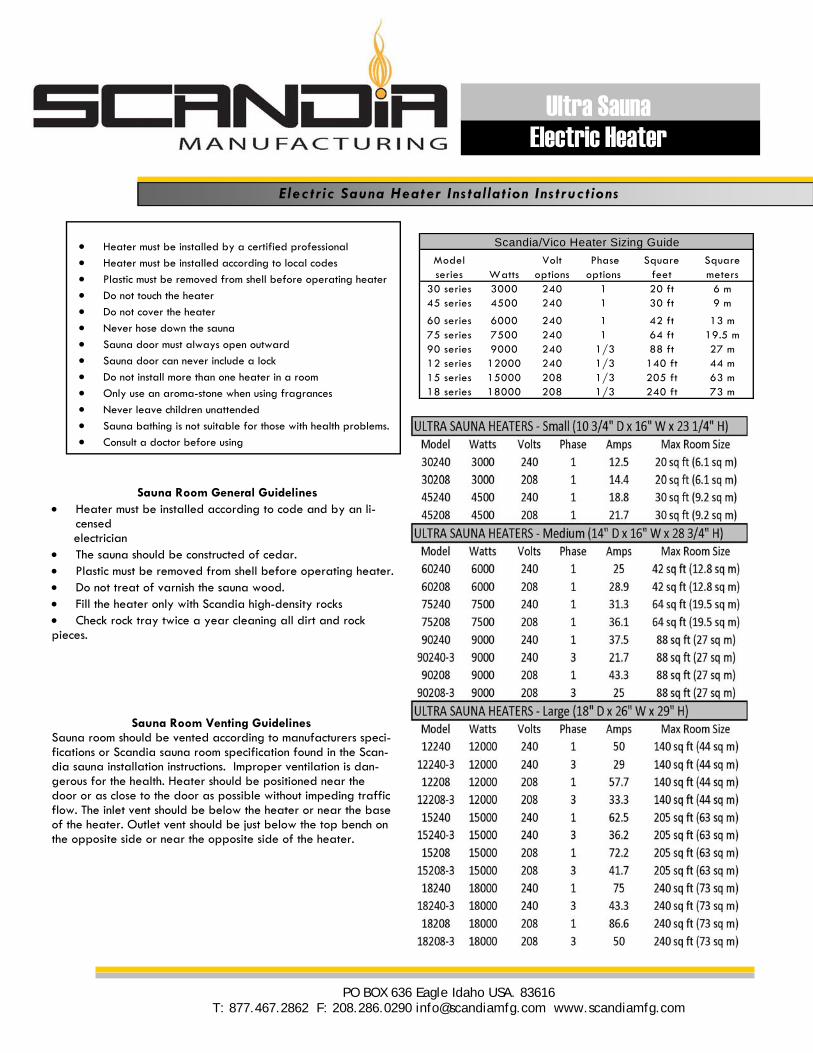
Heater must be installed by a certified professional Heater must be installed according to local codes Plastic must be removed from shell before operating heater Do not touch the heater Do not cover the heater Never hose down the sauna Sauna door must always open outward Sauna door can never include a lock Do not install more than one heater in a room Only use an aroma-stone when using fragrances Never leave children unattended Sauna bathing is not suitable for those with health problems. Consult a doctor before using Sauna Room Venting Guidelines Sauna room should be vented according to manufacturers speci- fications or Scandia sauna room specification found in the Scan- dia sauna installation instructions. Improper ventilation is dan- gerous for the health. Heater should be positioned near the door or as close to the door as possible without impeding traffic flow. The inlet vent should be below the heater or near the base of the heater. Outlet vent should be just below the top bench on the opposite side or near the opposite side of the heater. Sauna Room General Guidelines Heater must be installed according to code and by an li- censed electrician The sauna should be constructed of cedar. Plastic must be removed from shell before operating heater. Do not treat of varnish the sauna wood. Fill the heater only with Scandia high-density rocks Check rock tray twice a year cleaning all dirt and rock pieces. Model series Watts Volt options Phase options Square feet Square meters 30 series 3000 240 1 20 ft 6 m 45 series 4500 240 1 30 ft 9 m 60 series 6000 240 1 42 ft 13 m 75 series 7500 240 1 64 ft 19.5 m 90 series 9000 240 1/3 88 ft 27 m 12 series 12000 240 1/3 140 ft 44 m 15 series 15000 208 1/3 205 ft 63 m 18 series 18000 208 1/3 240 ft 73 m Scandia/Vico Heater Sizing Guide Electric Sauna Heater Installation Instructions PO BOX 636 Eagle Idaho USA. 83616 T: 877.467.2862 F: 208.286.0290 [email protected] www.scandiamfg.com Ultra Sauna Electric Heater

Welcome message from author
This document is posted to help you gain knowledge. Please leave a comment to let me know what you think about it! Share it to your friends and learn new things together.
Transcript
Heater must be installed by a certified professional
Heater must be installed according to local codes
Plastic must be removed from shell before operating heater
Do not touch the heater
Do not cover the heater
Never hose down the sauna
Sauna door must always open outward
Sauna door can never include a lock
Do not install more than one heater in a room
Only use an aroma-stone when using fragrances
Never leave children unattended
Sauna bathing is not suitable for those with health problems.
Consult a doctor before using
Sauna Room Venting Guidelines Sauna room should be vented according to manufacturers speci-fications or Scandia sauna room specification found in the Scan-dia sauna installation instructions. Improper ventilation is dan-gerous for the health. Heater should be positioned near the door or as close to the door as possible without impeding traffic flow. The inlet vent should be below the heater or near the base of the heater. Outlet vent should be just below the top bench on the opposite side or near the opposite side of the heater.
Sauna Room General Guidelines Heater must be installed according to code and by an li-
censed electrician The sauna should be constructed of cedar. Plastic must be removed from shell before operating heater. Do not treat of varnish the sauna wood. Fill the heater only with Scandia high-density rocks Check rock tray twice a year cleaning all dirt and rock pieces.
Model series Watts
Volt options
Phase options
Square feet
Square meters
30 series 3000 240 1 20 ft 6 m45 series 4500 240 1 30 ft 9 m
60 series 6000 240 1 42 ft 13 m75 series 7500 240 1 64 ft 19.5 m90 series 9000 240 1/3 88 ft 27 m12 series 12000 240 1/3 140 ft 44 m15 series 15000 208 1/3 205 ft 63 m18 series 18000 208 1/3 240 ft 73 m
Scandia/Vico Heater Sizing Guide
E lectr ic Sauna Heater Ins ta l lat ion Ins t ruct ions
PO BOX 636 Eagle Idaho USA. 83616 T: 877.467.2862 F: 208.286.0290 [email protected] www.scandiamfg.com
Ultra Sauna Electric Heater
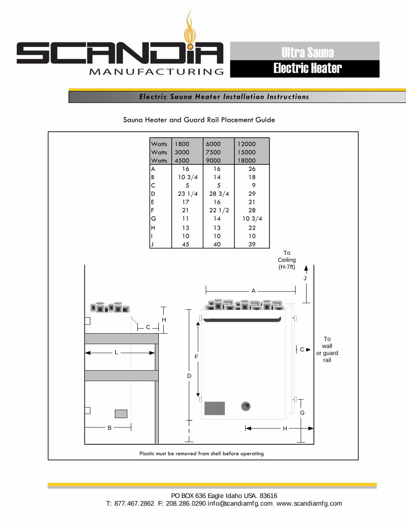
Sauna Heater and Guard Rail Placement Guide
A
J
ToCeiling(H-7ft)
C
Towall
or guardrail
G
I
D
H
HC
L
B
F
Watts 1800 6000 12000Watts 3000 7500 15000Watts 4500 9000 18000A 16 16 26B 10 3/4 14 18C 5 5 9D 23 1/4 28 3/4 29E 17 16 21F 21 22 1/2 28G 11 14 10 3/4
H 13 13 22I 10 10 10J 45 40 39
Plastic must be removed from shell before operating
E lectr ic Sauna Heater Ins ta l lat ion Ins t ruct ions
PO BOX 636 Eagle Idaho USA. 83616 T: 877.467.2862 F: 208.286.0290 [email protected] www.scandiamfg.com
Ultra Sauna Electric Heater
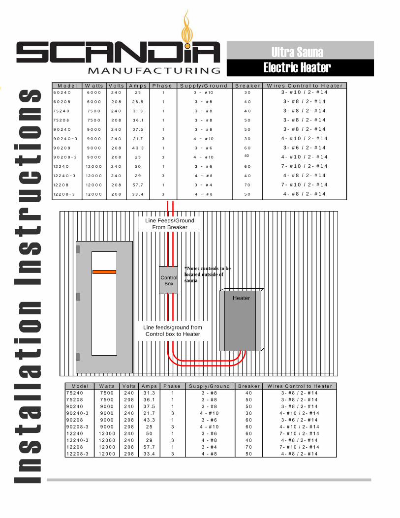
M o d e l W a t ts V o lt s A m p s P h a s e S u p p ly /G r o u n d B r e a k e r W ir e s C o n t r o l t o H e a te r6 0 2 4 0 6 0 0 0 2 4 0 2 5 1 3 - # 10 3 0 3 - # 1 0 / 2 - # 1 4
6 0 2 0 8 6 0 0 0 2 0 8 2 8 .9 1 3 - # 8 4 0 3 - # 8 / 2 - # 1 4
7 5 2 4 0 7 5 0 0 2 4 0 3 1 . 3 1 3 - # 8 4 0 3 - # 8 / 2 - # 1 4
7 5 2 0 8 7 5 0 0 2 0 8 3 6 . 1 1 3 - # 8 5 0 3 - # 8 / 2 - # 1 4
9 0 2 4 0 9 0 0 0 2 4 0 3 7 . 5 1 3 - # 8 5 0 3 - # 8 / 2 - # 1 4
9 0 2 4 0 - 3 9 0 0 0 2 4 0 2 1 . 7 3 4 - # 10 3 0 4 - # 1 0 / 2 - # 1 4
9 0 2 0 8 9 0 0 0 2 0 8 4 3 .3 1 3 - # 6 6 0 3 - # 6 / 2 - # 1 4
9 0 2 0 8 - 3 9 0 0 0 2 0 8 2 5 3 4 - # 10 6 0 4 - # 1 0 / 2 - # 1 4
1 2 2 4 0 1 2 0 0 0 2 4 0 5 0 1 3 - # 6 6 0 7 - # 1 0 / 2 - # 1 4
1 2 2 4 0 - 3 1 2 0 0 0 2 4 0 2 9 3 4 - # 8 4 0 4 - # 8 / 2 - # 1 4
1 2 2 0 8 1 2 0 0 0 2 0 8 5 7 . 7 1 3 - # 4 7 0 7 - # 1 0 / 2 - # 1 4
1 2 2 0 8 - 3 1 2 0 0 0 2 0 8 3 3 .4 3 4 - # 8 5 0 4 - # 8 / 2 - # 1 4
Line feeds/ground from Control box to Heater
Heater
ControlBox
Line Feeds/Ground From Breaker
M o d e l W a tts V o lts A m p s P h a s e S u p p ly /G ro u n d B re a k e r W ire s C o n tro l to H e a te r7 5 2 4 0 7 5 0 0 2 4 0 3 1 .3 1 3 - # 8 4 0 3 - # 8 / 2 - # 1 47 5 2 0 8 7 5 0 0 2 0 8 3 6 .1 1 3 - # 8 5 0 3 - # 8 / 2 - # 1 49 0 2 4 0 9 0 0 0 2 4 0 3 7 .5 1 3 - # 8 5 0 3 - # 8 / 2 - # 1 49 0 2 4 0 -3 9 0 0 0 2 4 0 2 1 .7 3 4 - # 1 0 3 0 4 - # 1 0 / 2 - # 1 49 0 2 0 8 9 0 0 0 2 0 8 4 3 .3 1 3 - # 6 6 0 3 - # 6 / 2 - # 1 49 0 2 0 8 -3 9 0 0 0 2 0 8 2 5 3 4 - # 1 0 6 0 4 - # 1 0 / 2 - # 1 41 2 2 4 0 1 2 0 0 0 2 4 0 5 0 1 3 - # 6 6 0 7 - # 1 0 / 2 - # 1 41 2 2 4 0 -3 1 2 0 0 0 2 4 0 2 9 3 4 - # 8 4 0 4 - # 8 / 2 - # 1 41 2 2 0 8 1 2 0 0 0 2 0 8 5 7 .7 1 3 - # 4 7 0 7 - # 1 0 / 2 - # 1 41 2 2 0 8 -3 1 2 0 0 0 2 0 8 3 3 .4 3 4 - # 8 5 0 4 - # 8 / 2 - # 1 4
40
*Note: controls to be located outside of sauna
Inst
alla
tion
Ins
truc
tion
s Ultra Sauna
Electric Heater
L1T1
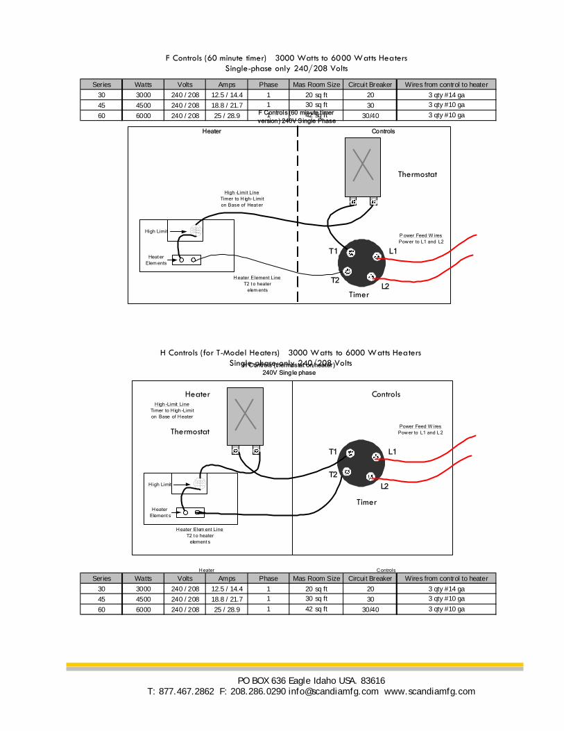
F Controls (60 minute timer version) 240V Single Phase
P ower Feed W iresPow er to L1 and L2
T2L2
H eater Element LineT2 t o heater
elem ents
High -Limit LineTimer to H igh-Limit on Base of Heat er
High Limit
Heat erElem ents
Heater Controls
Series Watts Volts Amps Phase Mas Room Size Circuit Breaker Wires from control to heater
30 3000 240 / 208 12.5 / 14.4 1 20 sq ft 20 3 qty #14 ga
45 4500 240 / 208 18.8 / 21.7 1 30 sq ft 30 3 qty #10 ga
60 6000 240 / 208 25 / 28.9 1 42 sq ft 30/40 3 qty #10 ga
F Controls (60 minute timer) 3000 Watts to 6000 Watts Heaters Single-phase only 240/208 Volts
H Controls (for T-Model Heaters) 3000 Watts to 6000 Watts Heaters Single-phase only 240/208 Volts
Timer
Thermostat
L1T1
H Controls (thermostat on heater ) 240V Single phase
Power Feed W iresPow er to L1 and L 2
T2
L2
H eater Elem ent LineT2 t o heater
element s
H igh -Limit LineTimer to H igh -Limit on Base of H eater
H igh Limit
H eaterElement s
H eater C ontrols
Heater Controls
Timer
Thermostat
Series Watts Volts Amps Phase Mas Room Size Circuit Breaker Wires from control to heater
30 3000 240 / 208 12.5 / 14.4 1 20 sq ft 20 3 qty #14 ga
45 4500 240 / 208 18.8 / 21.7 1 30 sq ft 30 3 qty #10 ga
60 6000 240 / 208 25 / 28.9 1 42 sq ft 30/40 3 qty #10 ga
PO BOX 636 Eagle Idaho USA. 83616 T: 877.467.2862 F: 208.286.0290 [email protected] www.scandiamfg.com
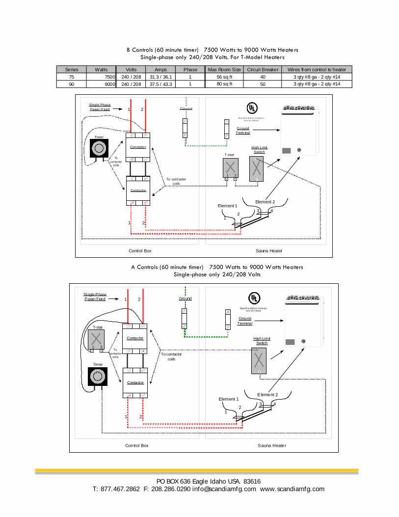
B Controls (60 minute timer) 7500 Watts to 9000 Watts Heaters Single-phase only 240/208 Volts. For T-Model Heaters
Series Watts Volts Amps Phase Mas Room Size Circuit Breaker Wires from control to heater
75 7500 240 / 208 31.3 / 36.1 1 56 sq ft 40 3 qty #8 ga - 2 qty #14
90 9000 240 / 208 37.5 / 43.3 1 80 sq ft 50 3 qty #8 ga - 2 qty #14
GroundSIngle Phase Power Feed
Contactor
Contactor
1 2
Control Box Sauna Heater
High Limit Switch
Ground Terminal
Scandia electric heaters
are UL listed
1 2
Element 1Element 2
42
1
3
1 2
Timer
T-stat
To contactor coils
To contactor
coi ls
Groun dSIngle Phase Powe r Feed
Con tacto r
Conta ctor
1 2
Control Box Sauna Heater
High Limit Switch
Ground Term inal
Scandi a el ec tri c heate rs
a re U L listed
1 2
Element 1Element 2
42
1
3
1 2
T-stat
To cont actor coils
To contactor
co ils
Timer
A Controls (60 minute timer) 7500 Watts to 9000 Watts Heaters Single-phase only 240/208 Volts
PO BOX 636 Eagle Idaho USA. 83616 T: 877.467.2862 F: 208.286.0290 [email protected] www.scandiamfg.com
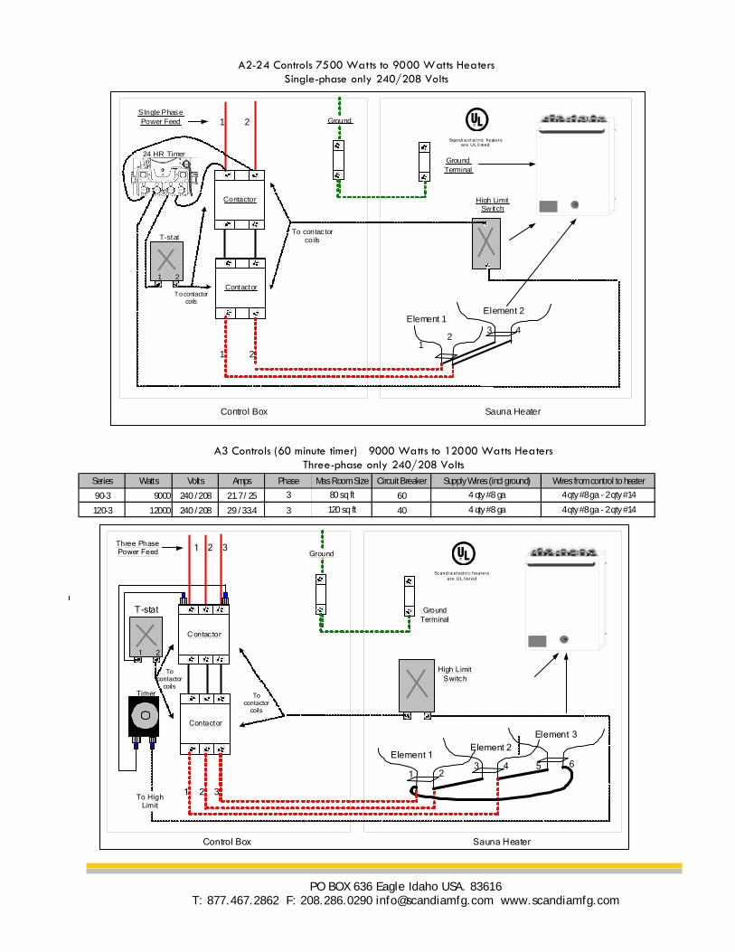
Series Watts Volts Amps Phase Mas Room Size Circuit Breaker Supply Wires (incl ground) Wires from control to heater
90-3 9000 240 / 208 21.7 / 25 3 80 sq ft 60 4 qty #8 ga 4 qty #8 ga - 2 qty #14
120-3 12000 240 / 208 29 / 33.4 3 120 sq ft 40 4 qty #8 ga 4 qty #8 ga - 2 qty #14
GroundSIngle Phase Power Feed
Contactor
Contactor
1 2
Control Box Sauna Heater
High Limit Sw itch
Ground Terminal
Scandia electric heaters
are UL li sted
1 2
Element 1Element 2
42
1
3
1 2
24 HR Timer
T-statTo contac tor
coils
To contactor coils
A2-24 Controls 7500 Watts to 9000 Watts Heaters Single-phase only 240/208 Volts
A3 Controls (60 minute timer) 9000 Watts to 12000 Watts Heaters Three-phase only 240/208 Volts
GroundThree Phase Power Feed
C ontac tor
Contactor
1 2 3
Control Box Sauna Heater
High Limit Switch
Ground Terminal
Scandia electric heaters
are UL l isted
1 2 3To High
Limit
Element 1Element 2
Element 3
5421
3 6
1 2
To contactor
coils
To contactor
coils
Timer
T-stat
PO BOX 636 Eagle Idaho USA. 83616 T: 877.467.2862 F: 208.286.0290 [email protected] www.scandiamfg.com
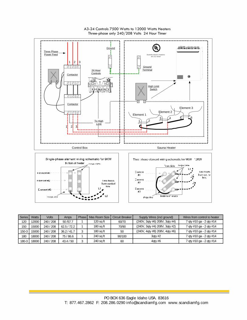
GroundThree PhasePower Feed
Contactor
Contactor
1 2 3
1 2
Control Box Sauna Heater
High LimitSwitch
GroundTerminal
Scandia electric heaters
are UL listed
1 2 3
To HighLimit
Element 1Element 2
Element 3
5421
3 6
24 HourControls
A3-24 Controls 7500 Watts to 12000 Watts Heaters Three-phase only 240/208 Volts 24 Hour TImer
Series Watts Volts Amps Phase Mas Room Size Circuit Breaker Supply Wires (incl ground) Wires from control to heater
120 12000 240 / 208 50 /57.7 1 120 sq ft 60/70 (240V, 3qty #6) 208V, 3qty #4) 7 qty #10 ga - 2 qty #14
150 15000 240 / 208 62.5 / 72.2 1 180 sq ft 70/90 (240V, 3qty #4) 208V, 3qty #2) 7 qty #10 ga - 2 qty #14
150-3 15000 240 / 208 36.2 / 41.7 3 180 sq ft 50 (240V, 4qty #8) 208V, 4qty #6) 7 qty #10 ga - 2 qty #14
180 18000 240 / 208 75 / 86.6 1 240 sq ft 90/100 3qty #2 7 qty #10 ga - 2 qty #14
180-3 18000 240 / 208 43.4 / 50 3 240 sq ft 60 4qty #6 7 qty #10 ga - 2 qty #14
PO BOX 636 Eagle Idaho USA. 83616 T: 877.467.2862 F: 208.286.0290 [email protected] www.scandiamfg.com
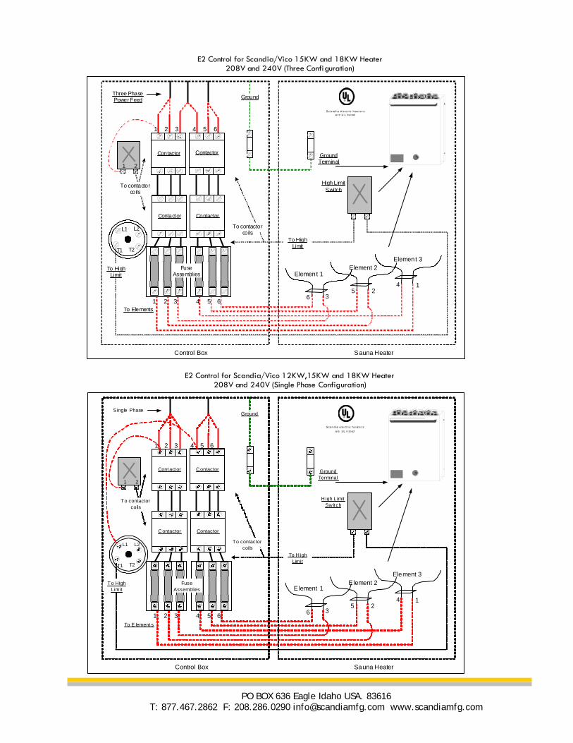
E2 Control for Scandia/Vico 15KW and 18KW Heater 208V and 240V (Three Configuration)
GroundThree Phase Power Feed
To Elements
Contactor
Contactor
Contactor
Contactor
1 2 3 4 5 6
T1 T2
L2L1
1 2
Control Box
1 2 3 4 5 6
Sauna Heater
Element 1Element 2
Element 3
65
4
32
1
To High Limit
To High Limit
High Limit Switch
Ground Terminal
FuseAssemblies
Sc andi a el ectric hea ters
a re U L lis ted
To contactor coils
To contactor coils
GroundSingle Phase
To E lement s
Cont act or
Contactor
Contactor
Contactor
1 2 3 4 5 6
T1 T2
L2L1
1 2
Control Box
1 2 3 4 5 6
Sauna Heater
Element 1Element 2
Element 3
65
4
32
1
To High Limit
To H igh Limit
H igh Limit Sw it ch
Ground Terminal
FuseAssemblies
Scandia e le ctric heate rs
are UL li sted
To contactor coils
To contactor coils
E2 Control for Scandia/Vico 12KW,15KW and 18KW Heater 208V and 240V (Single Phase Configuration)
PO BOX 636 Eagle Idaho USA. 83616 T: 877.467.2862 F: 208.286.0290 [email protected] www.scandiamfg.com

A2 Control for Scandia/Vico 12KW, 15KW and 18KW Heaters -For THREE PHASE ONLY
GroundThree PhasePower Feed
To Elements
Contactor
Contactor
Contactor
Contactor
1 2 3 4 5 6
1 2
Contro l Box
1 2 3 4 5 6
Sauna Heater
Element 1Element 2
Element 3
65
4
32
1
To HighLimit
To HighLimit
High LimitSwitch
GroundTerminal
FuseAssemblies
Scandia electric heaters
are UL listed
A2 Control for Scandia/V ico 12KW, 15KW and 18KW Heaters - For S ing le PHASE ONLY
Groun dSingle Phase Pow er Feed
To Elem ents
C onta ctor
C o ntact or
C ontac tor
C on tact or
1 2 3 4 5 6
1 2
Contro l Box
1 2 3 4 5 6
Sauna H eater
Element 1Element 2
Element 3
65
4
32
1
To H igh Limit
To H igh Lim it
H igh Limit S w it ch
Grou nd Te rmina l
FuseA ssem blie s
S candia el ectric heate rs
are U L li sted
E2-24 Control for Scandia/Vico 12KW,15KW and 18KW Heater 208V and 240V (Single Phase Configuration) 24Hour Timer
E2-24 Control for Scandia/Vico 15KW and 18KW Heater 208V and 240V (Three Configuration) 24 Hour Timer
PO BOX 636 Eagle Idaho USA. 83616 T: 877.467.2862 F: 208.286.0290 [email protected] www.scandiamfg.com
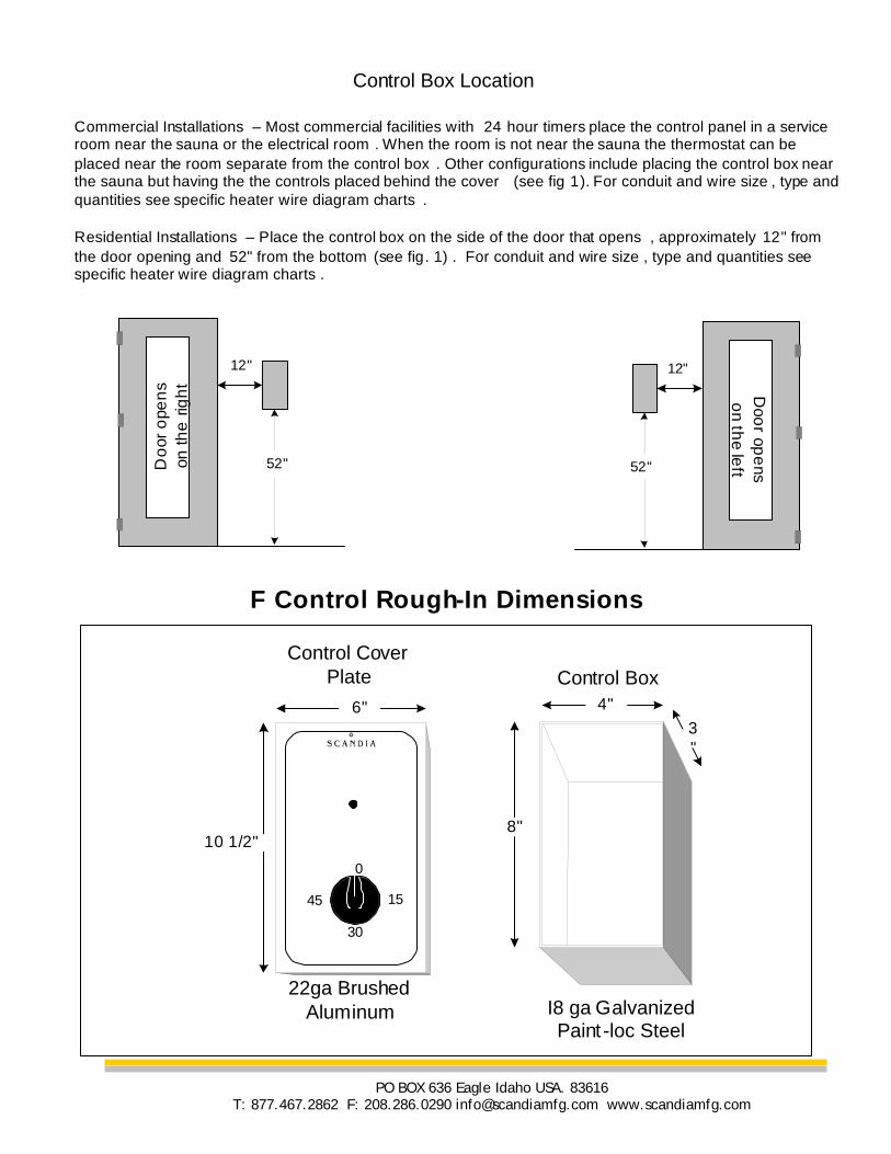
4"
8"
3"
10 1/2"
6"
0
1545
30
Control Cover Plate Control Box
22ga Brushed Aluminum I8 ga Galvanized
Paint -loc Steel
F Control Rough-In Dimensions
Commercial Installations – Most commercial facilities with 24 hour timers place the control panel in a service room near the sauna or the electrical room . When the room is not near the sauna the thermostat can be placed near the room separate from the control box . Other configurations include placing the control box near the sauna but having the the controls placed behind the cover (see fig 1). For conduit and wire size , type and quantities see specific heater wire diagram charts .
Residential Installations – Place the control box on the side of the door that opens , approximately 12" from the door opening and 52" from the bottom (see fig. 1) . For conduit and wire size , type and quantities see specific heater wire diagram charts .
Control Box Location
52"
12"
52"
12"
Do
or o
pen
s on
the
rig
ht D
oor op
ens
on th
e left
PO BOX 636 Eagle Idaho USA. 83616 T: 877.467.2862 F: 208.286.0290 [email protected] www.scandiamfg.com
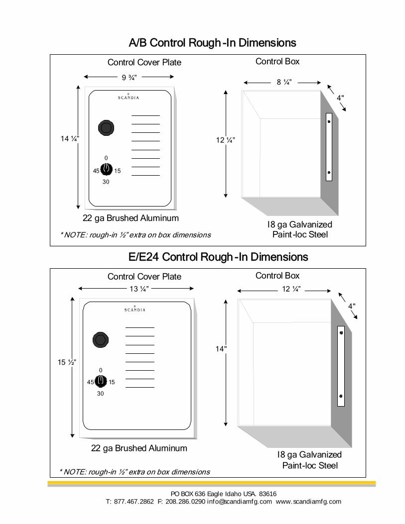
A/B Control Rough -In Dimensions
15 ½”
13 ¼”
0
1545
30
Control Cover Plate Control Box
22 ga Brushed AluminumI8 ga Galvanized
Paint-loc Steel
E/E24 Control Rough -In Dimensions
8 ¼”
12 ¼”
4"
14 ¼”
9 ¾”
0
1545
30
Control Cover Plate Control Box
22 ga Brushed AluminumI8 ga Galvanized
Paint -loc Steel* NOTE: rough-in ½” extra on box dimensions
* NOTE: rough-in ½” extra on box dimensions
12 ¼”
14"
4"
PO BOX 636 Eagle Idaho USA. 83616 T: 877.467.2862 F: 208.286.0290 [email protected] www.scandiamfg.com
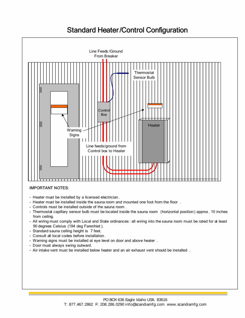
Line feeds/ground from Control box to Heater
Heater
ControlBox
Line Feeds /Ground From Breaker
IMPORTANT NOTES:
- Heater must be installed by a licensed electrician .- Heater must be installed inside the sauna room and mounted one foot from the floor .- Controls must be installed outside of the sauna room . - Thermostat capillary sensor bulb must be located inside the sauna room (horizontal position ) approx . 10 inches from ceiling. - All wiring must comply with Local and State ordinances : all wiring into the sauna room must be rated for at least 90 degrees Celsius (194 deg Farenhiet ). - Standard sauna ceiling height is 7 feet. - Consult all local codes before installation . - Warning signs must be installed at eye level on door and above heater . - Door must always swing outward.- Air intake vent must be installed below heater and an air exhaust vent should be installed .
Thermostat Sensor Bulb
WarningSigns
Standard Heater /Control Configuration
PO BOX 636 Eagle Idaho USA. 83616 T: 877.467.2862 F: 208.286.0290 [email protected] www.scandiamfg.com
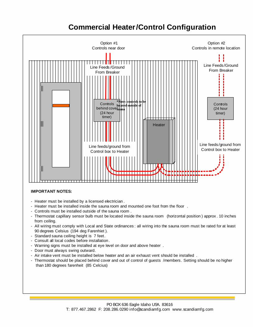
Line feeds/ground from Control box to Heater
Heater
Controls behind cover
(24 hour timer)
Line Feeds /Ground From Breaker
IMPORTANT NOTES:
- Heater must be installed by a licensed electrician .- Heater must be installed inside the sauna room and mounted one foot from the floor .- Controls must be installed outside of the sauna room . - Thermostat capillary sensor bulb must be located inside the sauna room (horizontal position ) approx . 10 inches from ceiling. - All wiring must comply with Local and State ordinances : all wiring into the sauna room must be rated for at least 90 degrees Celsius (194 deg Farenhiet ). - Standard sauna ceiling height is 7 feet . - Consult all local codes before installation . - Warning signs must be installed at eye level on door and above heater . - Door must always swing outward.- Air intake vent must be installed below heater and an air exhaust vent should be installed .- Thermostat should be placed behind cover and out of control of guests /members . Setting should be no higher than 180 degrees farenheit (85 Celcius)
Commercial Heater /Control Configuration
Option #1Controls near door
Controls (24 hour
timer)
Line Feeds/Ground From Breaker
Line feeds/ground from Control box to Heater
Option #2Controls in remote location
S di M f i C P O B 636 E l Id h USA 83616
*Note: controls to be located outside of sauna
PO BOX 636 Eagle Idaho USA. 83616 T: 877.467.2862 F: 208.286.0290 [email protected] www.scandiamfg.com
Related Documents