See discussions, stats, and author profiles for this publication at: https://www.researchgate.net/publication/285730692 Ultimate strength of ship structures Article · January 2011 CITATIONS 2 READS 23 3 authors: José Manuel Gordo University of Lisbon 55 PUBLICATIONS 409 CITATIONS SEE PROFILE A. P. Teixeira Technical University of Lisbon 68 PUBLICATIONS 571 CITATIONS SEE PROFILE Carlos Guedes Soares University of Lisbon 1,230 PUBLICATIONS 10,543 CITATIONS SEE PROFILE Available from: José Manuel Gordo Retrieved on: 11 April 2016

Welcome message from author
This document is posted to help you gain knowledge. Please leave a comment to let me know what you think about it! Share it to your friends and learn new things together.
Transcript

Seediscussions,stats,andauthorprofilesforthispublicationat:https://www.researchgate.net/publication/285730692
Ultimatestrengthofshipstructures
Article·January2011
CITATIONS
2
READS
23
3authors:
JoséManuelGordo
UniversityofLisbon
55PUBLICATIONS409CITATIONS
SEEPROFILE
A.P.Teixeira
TechnicalUniversityofLisbon
68PUBLICATIONS571CITATIONS
SEEPROFILE
CarlosGuedesSoares
UniversityofLisbon
1,230PUBLICATIONS10,543CITATIONS
SEEPROFILE
Availablefrom:JoséManuelGordo
Retrievedon:11April2016
1 INTRODUCTION
One important topic of research is the analysis of ship and offshore structures and, within this field, the ultimate strength of structural components at di-verse loading and environmental conditions has a great importance.
The subjects covered are related to typical ship plated components and systems, from unstiffened plates to the hull girder structural system. It includes analytical, numerical and experimental works ori-ented for the understanding and quantification of the behaviour of this type of structures.
The work on unstiffened plate elements covers the problems related to compression, combined load-ing and heat. Several design recommendations were proposed involving the contribution of degrading strength parameters like residual stresses, geometric initial imperfections and other aspects. A simplified formulation was also proposed to predict the whole average stress strain curve in pre and post collapse, which is very important for the evaluation of the per-formance of more complex structures.
The study of stiffened panels was mainly dedicat-ed to the experimental work on panels under com-pression having different configurations and materi-al. Nevertheless, simplified methods for the prediction of the load shortening curves of such pan-els were presented and the formulations have been adopted by some societies and researchers.
These simplified methods were also implemented in software for the evaluation of the hull girder per-formance under hogging and sagging conditions un-til collapse and beyond. The methodology proved to
be adequate for the study of intact or damaged ships of any kind.
Complementary, a large programme of experi-ments on box girders under pure bending was initi-ated in 2000 until now, involving different material and configurations that lead to different design pa-rameters.
2 STRENGTH OF PLATE ELEMENTS
Plate elements are the basis of ship structures to withstand local loads. They support the sea external pressure and internal cargo loads and transfer them to the ship hull girder through the stiffeners and frames. Since the major loads applied to plate ele-ments are in-plane loads and lateral pressure, it is of major interest the prediction of the load carrying ca-pacity of the ship plating under such loadings. In this context research work has been developed to charac-terise the effect of different parameters on ultimate strength of plates such as the aspect ratio and slen-derness of the plates, geometric imperfections and residual stresses. The influence of these parameters were analysed for several loading conditions such longitudinal compression (Guedes Soares & Kmiecik 1995; Gordo 2007, 2008; Sadovský et al 2002, 2004, 2005a, 2005b, 2006; Guedes Soares et al 2008), transverse (Guedes Soares & Gordo 1996a) and biaxial compression or lateral pressure (Guedes Soares & Gordo 1996b, Teixeira & Guedes Soares 2001). Also the degradation of strength due to non-uniform corrosion (Teixeira and Guedes Soares, 2008) and heat loads (Guedes Soares & Teixeira 2000, Guedes Soares et al 1998, 2000) are covered.
Ultimate strength of ship structures
J.M. Gordo, A.P. Teixeira & C. Guedes Soares
Centre for Marine Technology and Engineering (CENTEC), Instituto Superior Técnico,
Technical University of Lisbon, Portugal
ABSTRACT: This paper aims at reviewing some of the work that has been performed by the authors along the last years on the ultimate strength of structural elements and of the hull girder of ships. Particular empha-sis is given to the effect of several parameters on the strength of unstiffened plates and stiffened panels under longitudinal and transverse compression. Simplified methods to predict the load shortening curves of panels have been proposed and used for the evaluation of the hull girder strength under hogging and sagging bending moments. Experimental work on panels under compression and on box girders under pure bending, involving different materials and configurations is also described.
2.1 Longitudinal compression
The strength of unstiffened plate elements depends on several parameters related to material properties, plate’s geometry and geometric imperfections, re-sidual stresses due to fabrication, boundary condi-tions due to surrounding structure, and degradation due to aging, corrosion or damage.
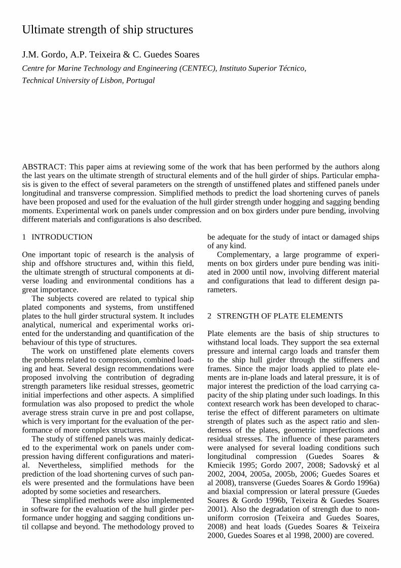
The main parameter is the plate’s slenderness, which is used to derive empirical formula predicting the entire load-shortening curve, including the post-collapse behaviour for pinned unstiffened plates with average levels of imperfections and residual stresses under longitudinal compression (Gordo & Guedes Soares 1993). The formulation is based on the concept of effective width and it allows correc-tions for different levels of residual stresses both in tension and compression, Figure 1.
Figure 1. Example of the effect of residual stresses (RS) on the
empirical load shortening curves of unstiffened plates (β=2)
Geometric imperfections may influence strongly
the strength of such plates. Its effect was dealt on studies considering different levels of amplitude of the imperfections, various configurations and levels of constraints (Guedes Soares & Kmiecik 1995; Gordo 2007, 2008; Sadovský et al 2005b, 2006; Guedes Soares et al 2008).
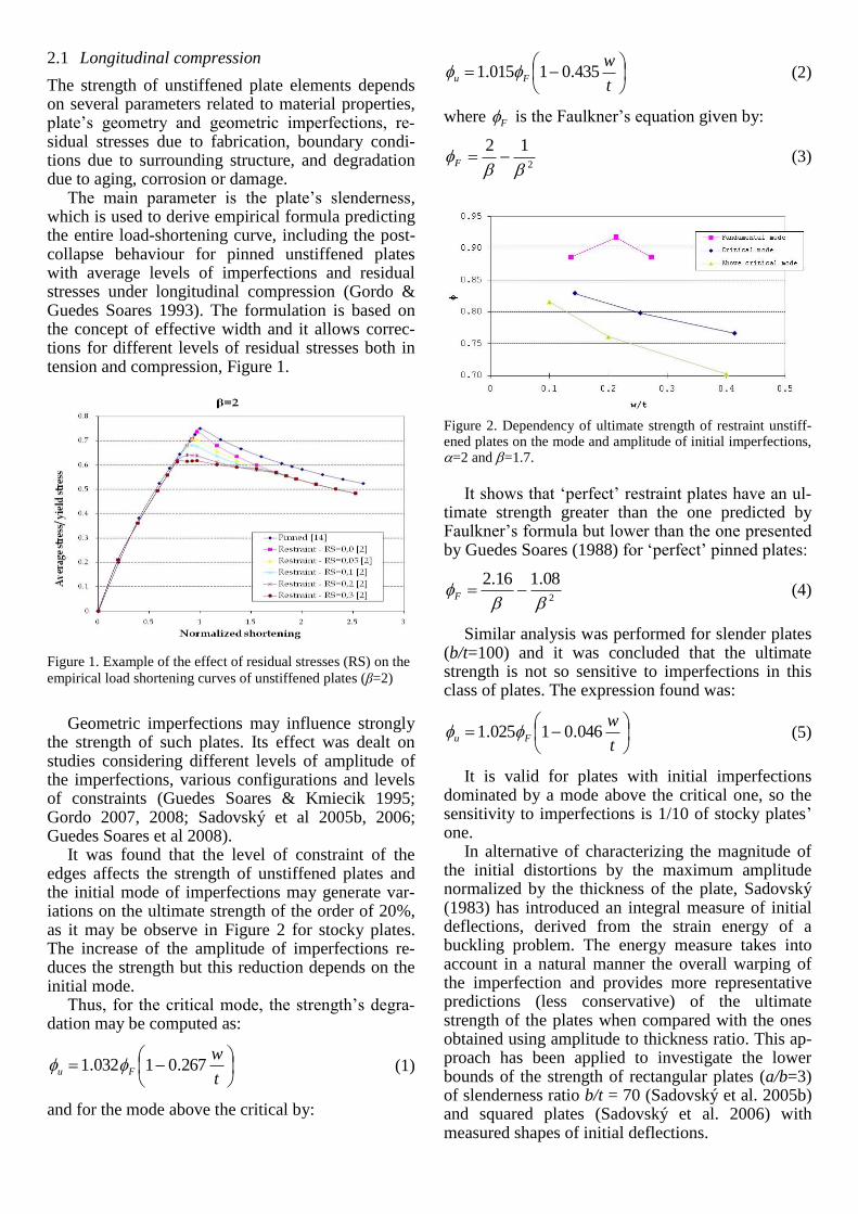
It was found that the level of constraint of the edges affects the strength of unstiffened plates and the initial mode of imperfections may generate var-iations on the ultimate strength of the order of 20%, as it may be observe in Figure 2 for stocky plates. The increase of the amplitude of imperfections re-duces the strength but this reduction depends on the initial mode.
Thus, for the critical mode, the strength’s degra-dation may be computed as:
t
wFu 267.01032.1
(1)
and for the mode above the critical by:
t
wFu 435.01015.1
(2)
where F is the Faulkner’s equation given by:
2
12
F
(3)
Figure 2. Dependency of ultimate strength of restraint unstiff-ened plates on the mode and amplitude of initial imperfections, =2 and =1.7.
It shows that ‘perfect’ restraint plates have an ul-
timate strength greater than the one predicted by Faulkner’s formula but lower than the one presented by Guedes Soares (1988) for ‘perfect’ pinned plates:
2
08.116.2
F
(4)
Similar analysis was performed for slender plates (b/t=100) and it was concluded that the ultimate strength is not so sensitive to imperfections in this class of plates. The expression found was:
t
wFu 046.01025.1
(5)
It is valid for plates with initial imperfections dominated by a mode above the critical one, so the sensitivity to imperfections is 1/10 of stocky plates’ one.
In alternative of characterizing the magnitude of the initial distortions by the maximum amplitude normalized by the thickness of the plate, Sadovský (1983) has introduced an integral measure of initial deflections, derived from the strain energy of a buckling problem. The energy measure takes into account in a natural manner the overall warping of the imperfection and provides more representative predictions (less conservative) of the ultimate strength of the plates when compared with the ones obtained using amplitude to thickness ratio. This ap-proach has been applied to investigate the lower bounds of the strength of rectangular plates (a/b=3) of slenderness ratio b/t = 70 (Sadovský et al. 2005b) and squared plates (Sadovský et al. 2006) with measured shapes of initial deflections.
It has been shown that for the buckling shapes of
initial deflections, significantly lower (conservative)
capacities have been obtained when adopting the
amplitude to thickness ratio instead of the energy
measure. Sadovský et al., (2004) have also shown
that the buckling mode is one of the most influential
eigenmode shapes, however, compound shapes can
result in lower collapse strength, and therefore, an
approximate procedure for assessment of the lower
bound of plate strength based on combinations of
buckling modes has been suggested. The assessment of lower bound capacities proved
to be of importance in probabilistic plate strength analysis, when considering initial deflections as a random field (Sadovský et al. 2005a).
In addition to the global initial distortions due to the fabrication process, local imperfections may also be present on the plates as a result of damages dur-ing ship operation. This has been pointed out by Dow & Smith (1983) who showed that the localized imperfections can have an important contribution on plate collapse strength, which was confirmed later by Ueda & Yao (1985) and more recently by Guedes Soares et al. (2008).
2.2 Transversal compression
The behaviour of unstiffened plates under transverse compression was investigated by performing a par-ametric study covering a wide range of plate aspect ratio (2<<5) and slenderness (0.85<<4.25) (Guedes Soares & Gordo 1996a). It was intended to validate the correction proposed to Valsgard’s for-mula.
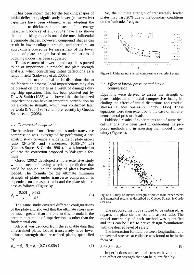
Gordo (2002) developed a more extensive study with the need of having a reliable prediction that could be applied on the study of plates biaxially loaded. The formula for the ultimate minimum strength of plates under transverse compression is dependent on the aspect ratio and the plate slender-ness as follows, (Figure 3):
2
593.0561.0
y
(6)
The same study covered different configurations of the plate and showed that the ultimate stress may be much greater than the one in this formula if the predominant mode of imperfections is other than the fundamental one.
Also, it was deduced from the available data that unrestrained plates loaded transversely have lower ultimate strength than restrained plates, quantified by:
05.07.0 ycyyu B
(7)
So, the ultimate strength of transversely loaded plates may vary 20% due to the boundary conditions on the ‘unloaded’ edges.
Figure 3. Ultimate transversal compressive strength of plates
2.3 Effect of lateral pressure and biaxial compression
Equations were derived to assess the strength of plates subjected to biaxial compressive loads, in-cluding the effect of initial distortions and residual stresses (Guedes Soares & Gordo 1996b). These equations were then extended to the case of simulta-neous lateral pressure loads.
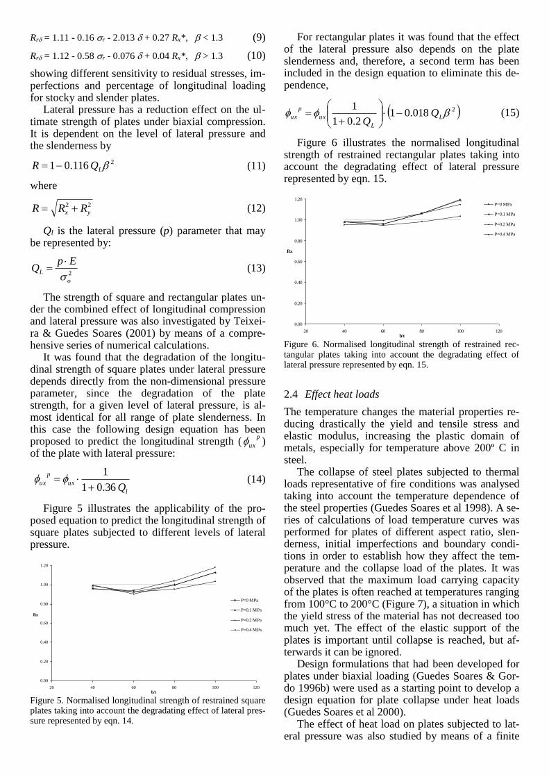
Published results of experiments and of numerical calculations have been used in calibrating the pro-posed methods and in assessing their model uncer-tainty (Figure 4).
Figure 4. Study on biaxial strength of plates from experiments and numerical results as described by Guedes Soares & Gordo (1996b)
The proposed methods showed to be unbiased, as
regards the plate slenderness and aspect ratio. The model uncertainty of each method was quantified and thus can be used to derive design formulations with the desired level of safety.
The interaction formula between longitudinal and transversal stresses at collapse was found to be in the form of:
Rx2 + Ry
2 = Rr2 (8)
Imperfections and residual stresses have a reduc-tion effect on strength that can be quantified by:
0.0
0.1
0.2
0.3
0.4
0.5
0.6
0.7
0.8
0.9
0.0 1.0 2.0 3.0 4.0 5.0
y 0561 0593
2
. .
Rr = 1.11 - 0.16 r - 2.013 + 0.27 Rx*, < 1.3 (9)
Rr = 1.12 - 0.58r - 0.076 + 0.04 Rx*, > 1.3 (10)
showing different sensitivity to residual stresses, im-perfections and percentage of longitudinal loading for stocky and slender plates.
Lateral pressure has a reduction effect on the ul-timate strength of plates under biaxial compression. It is dependent on the level of lateral pressure and the slenderness by
2116.01 LQR (11)
where
22
yx RRR (12)
Ql is the lateral pressure (p) parameter that may be represented by:
2
o
L
EpQ
(13)
The strength of square and rectangular plates un-der the combined effect of longitudinal compression and lateral pressure was also investigated by Teixei-ra & Guedes Soares (2001) by means of a compre-hensive series of numerical calculations.
It was found that the degradation of the longitu-dinal strength of square plates under lateral pressure depends directly from the non-dimensional pressure parameter, since the degradation of the plate strength, for a given level of lateral pressure, is al-most identical for all range of plate slenderness. In this case the following design equation has been proposed to predict the longitudinal strength (
p
ux ) of the plate with lateral pressure:
l
ux
p
uxQ 36.01
1
(14)
Figure 5 illustrates the applicability of the pro-posed equation to predict the longitudinal strength of square plates subjected to different levels of lateral pressure.
Figure 5. Normalised longitudinal strength of restrained square plates taking into account the degradating effect of lateral pres-sure represented by eqn. 14.
For rectangular plates it was found that the effect of the lateral pressure also depends on the plate slenderness and, therefore, a second term has been included in the design equation to eliminate this de-pendence,
2 018.01 2.01
1 L
L
ux
p
ux QQ
(15)
Figure 6 illustrates the normalised longitudinal strength of restrained rectangular plates taking into account the degradating effect of lateral pressure represented by eqn. 15.
Figure 6. Normalised longitudinal strength of restrained rec-tangular plates taking into account the degradating effect of lateral pressure represented by eqn. 15.
2.4 Effect heat loads
The temperature changes the material properties re-ducing drastically the yield and tensile stress and elastic modulus, increasing the plastic domain of metals, especially for temperature above 200º C in steel.
The collapse of steel plates subjected to thermal loads representative of fire conditions was analysed taking into account the temperature dependence of the steel properties (Guedes Soares et al 1998). A se-ries of calculations of load temperature curves was performed for plates of different aspect ratio, slen-derness, initial imperfections and boundary condi-tions in order to establish how they affect the tem-perature and the collapse load of the plates. It was observed that the maximum load carrying capacity of the plates is often reached at temperatures ranging from 100°C to 200°C (Figure 7), a situation in which the yield stress of the material has not decreased too much yet. The effect of the elastic support of the plates is important until collapse is reached, but af-terwards it can be ignored.
Design formulations that had been developed for plates under biaxial loading (Guedes Soares & Gor-do 1996b) were used as a starting point to develop a design equation for plate collapse under heat loads (Guedes Soares et al 2000).
The effect of heat load on plates subjected to lat-eral pressure was also studied by means of a finite
0.00
0.20
0.40
0.60
0.80
1.00
1.20
20 40 60 80 100 120b/t
Rx
P=0 MPa
P=0.1 MPa
P=0.2 MPa
P=0.4 MPa
0.00
0.20
0.40
0.60
0.80
1.00
1.20
20 40 60 80 100 120b/t
Rx
P=0 MPa
P=0.1 MPa
P=0.2 MPa
P=0.4 MPa
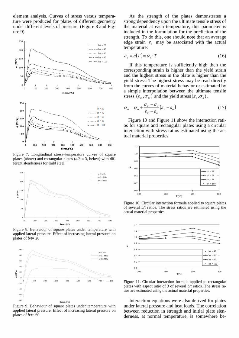
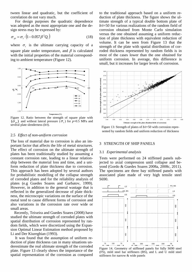
element analysis. Curves of stress versus tempera-ture were produced for plates of different geometry under different levels of pressure, (Figure 8 and Fig-ure 9).
Figure 7. Longitudinal stress–temperature curves of square plates (above) and rectangular plates (a/b 3, below) with dif-ferent slenderness for mild steel
Figure 8. Behaviour of square plates under temperature with applied lateral pressure. Effect of increasing lateral pressure on plates of b/t= 20
Figure 9. Behaviour of square plates under temperature with applied lateral pressure. Effect of increasing lateral pressure on plates of b/t= 60
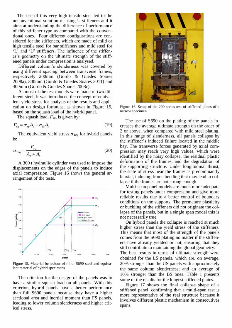
As the strength of the plates demonstrates a strong dependency upon the ultimate tensile stress of the material at each temperature, this parameter is included in the formulation for the prediction of the strength. To do this, one should note that an average edge strain a may be associated with the actual temperature:
TT ta
(16)
If this temperature is sufficiently high then the corresponding strain is higher than the yield strain and the highest stress in the plate is higher than the yield stress. The highest stress may be read directly from the curves of material behavior or estimated by a simple interpolation between the ultimate tensile stress ),( mm and the yield stress ),( oo .
oa
om
omoa
(17)
Figure 10 and Figure 11 show the interaction rati-os for square and rectangular plates using a circular interaction with stress ratios estimated using the ac-tual material properties.
Figure 10. Circular interaction formula applied to square plates of several b/t ratios. The stress ratios are estimated using the actual material properties.
Figure 11. Circular interaction formula applied to rectangular plates with aspect ratio of 3 of several b/t ratios. The stress ra-tios are estimated using the actual material properties.
Interaction equations were also derived for plates
under lateral pressure and heat loads. The correlation between reduction in strength and initial plate slen-derness, at normal temperature, is somewhere be-
0
50
100
150
200
250
0 100 200 300 400 500 600 700 800
Temp. (ºC)
(
MP
a)
b/t = 20
b/t = 40
b/t = 60
b/t = 80
b/t = 100
0
50
100
150
200
250
0 100 200 300 400 500 600 700 800
Temp. (ºC)
(
MP
a)
p=0 MPa
p=0.1 MPa
p=0.5 MPa
-80
-60
-40
-20
0
20
40
60
80
100
0 100 200 300 400 500 600 700 800
Temp. (ºC)
(
MP
a)
p=0 MPa
p=0.1 MPa
p=0.5 MPa
0.0
0.2
0.4
0.6
0.8
1.0
1.2
200 400 600 800T (ºC)
R
b/t = 40
b/t = 60
b/t = 80
b/t = 100
0.0
0.2
0.4
0.6
0.8
1.0
1.2
1.4
200 400 600 800T(ºC)
R
b/t = 40
b/t = 60
b/t = 80
b/t = 100
tween linear and quadratic, but the coefficient of correlation do not vary much.
For design purposes the quadratic dependence was adopted as the most appropriate one and the de-sign stress may be expressed by:
ltpt Q2057.01 (18)
where t is the ultimate carrying capacity of a
square plate under temperature, and is calculated
with the initial properties of the material correspond-
ing to ambient temperature (Figure 12).
Figure 12. Ratio between the strength of square plate with
)( pt and without lateral pressure ( t ) for p=0.5 MPa and several plate slenderness (b/t).
2.5 Effect of non-uniform corrosion
The loss of material due to corrosion is also an im-portant factor that affects the life of metal structures. The effect of corrosion on the ultimate strength of plates has been traditionally studied by assuming a constant corrosion rate, leading to a linear relation-ship between the material loss and time, and a uni-form reduction of plate thickness due to corrosion. This approach has been adopted by several authors for probabilistic modelling of the collapse strength of corroded plates and for the reliability analysis of plates (e.g Guedes Soares and Garbatov, 1999). However, in addition to the general wastage that is reflected in the generalized decrease of plate thick-ness, the microscopic variations on the surface of the metal tend to cause different forms of corrosion and also variations in the corrosion rate over wide or small areas.
Recently, Teixeira and Guedes Soares (2008) have studied the ultimate strength of corroded plates with spatial distribution of corrosion represented by ran-dom fields, which were discretized using the Expan-sion Optimal Linear Estimation method proposed by Li and Der Kiureghian (1993).
It was found that the assumption of uniform re-duction of plate thickness can in many situations un-derestimate the real ultimate strength of the corroded plate. Figure 13 clearly shows the importance of the spatial representation of the corrosion as compared
to the traditional approach based on a uniform re-duction of plate thickness. The figure shows the ul-timate strength of a typical double bottom plate of b/t=50 for various realizations of the random field of corrosion obtained from Monte Carlo simulation versus the one obtained assuming a uniform reduc-tion of plate thickness with equivalent reduction of volume. It can be seen from Figure 13 that the strength of the plate with spatial distribution of cor-roded thickness represented by random fields is in most of the cases lower than the one obtained for uniform corrosion. In average, this difference is small, but it increases for larger levels of corrosion.
Figure 13: Strength of plates of b/t=50 with corrosion repre-
sented by random fields and uniform reduction of thickness
3 STRENGTH OF SHIP PANELS
3.1 Experimental analysis
Tests were performed on 24 stiffened panels sub-jected to axial compression until collapse and be-yond (Gordo & Guedes Soares 2008a, 2008c, 2011). The specimens are three bay stiffened panels with associated plate made of very high tensile steel S690.
40
04
00
40
0
75
LS
FS, BS
75150
US
150
40
04
00
40
0
US
FS, BS
LS
15015075 75
Figure 14. Geometry of stiffened panels for fully S690 steel (FS), mild steel bar stiffeners (BS), and L and U mild steel stiffeners for narrow & wide panels
-1.50
-1.00
-0.50
0.00
0.50
1.00
0 100 200 300 400 500 600
Temperatura (ºC)
pt
t
20
40
60
80
100
0.58
0.60
0.62
0.64
0.66
0.68
0.70
0.72
0.74
0.76
0.78
0.80
0.58 0.60 0.62 0.64 0.66 0.68 0.70 0.72 0.74 0.76 0.78 0.80
Ultimate strength of the plate (Random fields of corrosion)
Ult
ima
te s
tren
gth
of
the p
late
(u
nif
orm
co
rro
sio
n)
The use of this very high tensile steel led to the unconventional solution of using U stiffeners and it aims at understanding the difference of performance of this stiffener type as compared with the conven-tional ones. Four different configurations are con-sidered for the stiffeners, which are made of mild or high tensile steel for bar stiffeners and mild steel for ‘L’ and ‘U’ stiffeners. The influence of the stiffen-er’s geometry on the ultimate strength of the stiff-ened panels under compression is analysed.
Different column’s slenderness was covered by using different spacing between transverse frames, respectively 200mm (Gordo & Guedes Soares 2008a), 300mm (Gordo & Guedes Soares 2011) and 400mm (Gordo & Guedes Soares 2008c).
As most of the test models were made of two dif-ferent steel, it was introduced the concept of equiva-lent yield stress for analysis of the results and appli-cation on design formulas, as shown in Figure 15, based on the squash load of the hybrid panel.
The squash load, Fsq, is given by:
sYspYpsq AAF
(19)
The equivalent yield stress Yeq for hybrid panels is:
sp
sq
YeqAA
F
(20)
A 300 t hydraulic cylinder was used to impose the displacements on the edges of the panels to induce axial compression. Figure 16 shows the general ar-rangement of the tests.
Figure 15. Material behaviour of mild, S690 steel and equiva-lent material of hybrid specimens
The criterion for the design of the panels was to
have a similar squash load on all panels. With this criterion, hybrid panels have a better performance than full S690 panels because they have a higher sectional area and inertial moment than FS panels, leading to lower column slenderness and higher crit-ical stress.
Figure 16. Setup of the 200 series test of stiffened plates of a narrow specimen
The use of S690 on the plating of the panels in-
creases the average ultimate strength on the order of 2 or above, when compared with mild steel plating. In this range of slenderness, all panels collapse by the stiffener’s induced failure located in the middle bay. The transverse forces generated by axial com-pression may reach very high values, which were identified by the noisy collapse, the residual plastic deformation of the frames, and the degradation of the supporting structure. Under longitudinal thrust, the state of stress near the frames is predominantly biaxial, inducing frame bending that may lead to col-lapse if the frames are not strong enough.
Multi-span panel models are much more adequate for testing panels under compression and give more reliable results due to a better control of boundary conditions on the supports. The premature plasticity or buckling of the stiffeners did not originate the col-lapse of the panels, but in a single span model this is not necessarily true.
On hybrid panels the collapse is reached at much higher stress than the yield stress of the stiffeners. This means that most of the strength of the panels comes from the S690 plating no matter if the stiffen-ers have already yielded or not, ensuring that they still contribute to maintaining the global geometry. The best results in terms of ultimate strength were
obtained for the LS panels, which are, on average,
20% stronger than the US panels with approximately
the same column slenderness; and an average of
10% stronger than the BS ones. Table 1 presents
some of the results for the longest stiffened plates. Figure 17 shows the final collapse shape of a
stiffened panel, confirming that a multi-span test is more representative of the real structure because it involves different plastic mechanism in consecutives spans.
0
100
200
300
400
500
600
700
800
0 0.001 0.002 0.003 0.004 0.005 0.006
Strain
Str
es
s (
MP
a)
BS Steel
S69 steel
Equiv. Steel
Hybrid Section
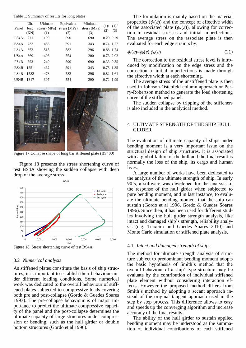
Table 1. Summary of results for long plates
Panel
Ult.
load
(KN)
Ultimate
stress (MPa)
(1)
Equivalent
stress (MPa)
(2)
Minimum
stress (MPa)
(3)
(1)/
(2)
(1)/
(3)
FS4A 271 199 690 690 0.29 0.29
BS4A 732 436 591 343 0.74 1.27
LS4A 853 515 582 296 0.88 1.74
US4A 669 403 554 200 0.73 2.02
FS4B 653 240 690 690 0.35 0.35
BS4B 1551 462 591 343 0.78 1.35
LS4B 1582 478 582 296 0.82 1.61
US4B 1317 397 554 200 0.72 1.99
Figure 17.Collapse shape of long bar stiffened plate (BS400)
Figure 18 presents the stress shortening curve of
test BS4A showing the sudden collapse with deep drop of the average stress.
Figure 18. Stress shortening curve of test BS4A.
3.2 Numerical analysis
As stiffened plates constitute the basis of ship struc-tures, it is important to establish their behaviour un-der different loading conditions. Some numerical work was dedicated to the overall behaviour of stiff-ened plates subjected to compressive loads covering both pre and post-collapse (Gordo & Guedes Soares 1993). The pre-collapse behaviour is of major im-portance to predict the ultimate compressive capaci-ty of the panel and the post-collapse determines the ultimate capacity of large structures under compres-sion or bending, such as the hull girder or double bottom structures (Gordo et al 1996).
The formulation is mainly based on the material properties (e()) and the concept of effective width of the associated plate (w()), allowing for correc-tion to residual stresses and initial imperfections. The average stress on the associate plate is then evaluated for each edge strain by:
p()=e().w() (21)
The correction to the residual stress level is intro-duced by modification on the edge stress and the correction to initial imperfections is made through the effective width at each shortening.
The average stress of the unstiffened plate is then used in Johnson-Ostenfeld column approach or Per-ry-Robertson method to generate the load shortening curve of the stiffened panel.
The sudden collapse by tripping of the stiffeners is also included in the analytical method.
4 ULTIMATE STRENGTH OF THE SHIP HULL GIRDER
The evaluation of ultimate capacity of ships under bending moment is a very important issue on the structural design of ship structures. It is associated with a global failure of the hull and the final result is normally the loss of the ship, its cargo and human lives.
A large number of works have been dedicated to the analysis of the ultimate strength of ship. In early 90’s, a software was developed for the analysis of the response of the hull girder when subjected to pure bending moment, and in last instance, to evalu-ate the ultimate bending moment that the ship can sustain (Gordo et al 1996, Gordo & Guedes Soares 1996). Since then, it has been used for different stud-ies involving the hull girder strength analysis, like intact and damaged ship’s strength, reliability analy-sis (e.g. Teixeira and Guedes Soares 2010) and Monte Carlo simulation or stiffened plate analysis.
4.1 Intact and damaged strength of ships
The method for ultimate strength analysis of struc-ture subject to predominant bending moment adopts the basic hypothesis of Smith’s method that the overall behaviour of a ship’ type structure may be evaluate by the contribution of individual stiffened plate element without considering interaction ef-fects. However the proposed method differs from Smith’s method by adopting a secant approach in-stead of the original tangent approach used in the step by step process. This difference allows to easy and speeds up the converging algorithm and increase accuracy of the final results.
The ability of the hull girder to sustain applied bending moment may be understood as the summa-tion of individual contributions of each stiffened
BS4A
0
50
100
150
200
250
300
350
400
450
500
0 0,001 0,002 0,003 0,004 0,005 0,006
dL/L
Str
ess (
MP
a)
1st cycle
2nd cycle
3rd cycle
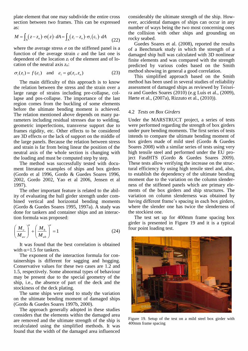
plate element that one may subdivide the entire cross section between two frames. This can be expressed as:
n i n i iA A
M z z z dA z z dA (22)
where the average stress σ on the stiffened panel is a function of the average strain ε and the last one is dependent of the location zi of the element and of lo-cation of the neutral axis zn:
),(and)()( niiiii zzgfz
(23)
The main difficulty of this approach is to know the relation between the stress and the strain over a large range of strains including pre-collapse, col-lapse and pos-collapse. The importance of the last region comes from the buckling of some elements before the ultimate bending moment is achieved. The relation mentioned above depends on many pa-rameters including residual stresses due to welding, geometric imperfections, transverse support due to frames rigidity, etc. Other effects to be considered are 3D effects or the lack of support on the middle of the large panels. Because the relation between stress and strain is far from being linear the position of the neutral axis of the whole section is changing with the loading and must be computed step by step.
The method was successfully tested with docu-ment literature examples of ships and box girders (Gordo et al 1996, Gordo & Guedes Soares 1996, 2002, Gordo 2002, Yao et al 2006, Jensen et al 1997).
The other important feature is related to the abil-ity of evaluating the hull girder strength under com-bined vertical and horizontal bending moments (Gordo & Guedes Soares 1995, 1997a). A study was done for tankers and container ships and an interac-tion formula was proposed:
1
uh
h
uv
v
M
M
M
M (24)
It was found that the best correlation is obtained with =1.5 for tankers.
The exponent of the interaction formula for con-tainerships is different for sagging and hogging. Conservative values for these two cases are 1.2 and 1.5, respectively. Some abnormal types of behaviour may be present due to the special geometry of the ship, i.e., the absence of part of the deck and the stockiness of the deck plating.
The same ships were used to study the variation on the ultimate bending moment of damaged ships (Gordo & Guedes Soares 1997b, 2000).
The approach generally adopted in these studies considers that the elements within the damaged area are removed and the ultimate strength of the ship is recalculated using the simplified methods. It was found that the width of the damaged area influenced
considerably the ultimate strength of the ship. How-ever, accidental damages of ships can occur in any number of ways being the two most concerning ones the collision with other ships and grounding on rocky seabed.
Guedes Soares et al. (2008), reported the results of a Benchmark study in which the strength of a damaged ship hull was calculated with 3D nonlinear finite elements and was compared with the strength predicted by various codes based on the Smith method showing in general a good correlation.
This simplified approach based on the Smith method has been used in several studies of reliability assessment of damaged ships as reviewed by Teixei-ra and Guedes Soares (2010) (e.g Luís et al., (2009), Hørte et al., (2007a), Rizzuto et al., (2010)).
4.2 Tests on Box Girders
Under the MARSTRUCT project, a series of tests were performed regarding the strength of box girders under pure bending moments. The first series of tests intends to compare the ultimate bending moment of box girders made of mild steel (Gordo & Guedes Soares 2008) with a similar series of tests using very high tensile steel and performed under the EU pro-ject FasdHTS (Gordo & Guedes Soares 2009). These tests allow verifying the increase on the struc-tural efficiency by using high tensile steel and, also, to establish the dependency of the ultimate bending moment due to the variation on the column slender-ness of the stiffened panels which are primary ele-ments of the box girders and ship structures. The variation on column slenderness was obtained by having different frame’s spacing in each box girders, where the slender one has twice the slenderness of the stockiest one.
The test set up for 400mm frame spacing box girder is presented in Figure 19 and it is a typical four point loading test.
Figure 19. Setup of the test on a mild steel box girder with 400mm frame spacing
The tests showed that the performance of the box girders are as expected and the performance of the high tensile steel model is very good obtaining a global efficiency slightly lower than the maximum available which is 2.56 due to the difference of the yield stress of the two different materials employed. The lower value results from the effect of the in-crease on the column slenderness of the panel under compression when the yield stress of the material in-creases.
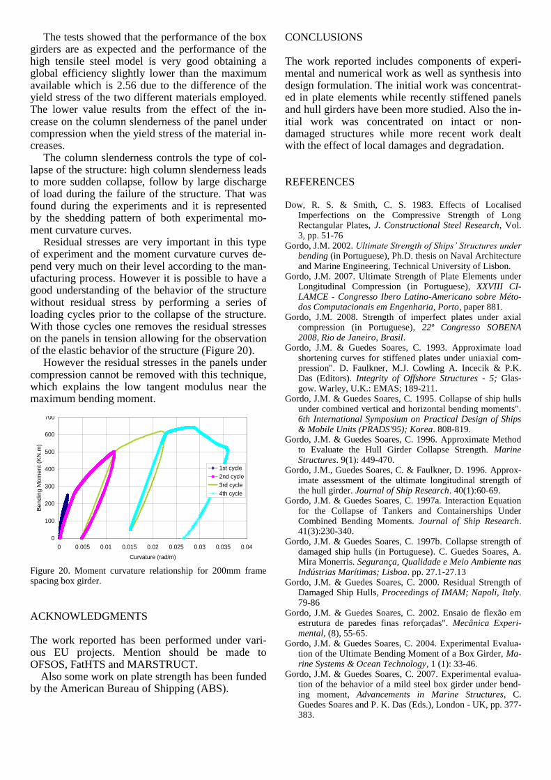
The column slenderness controls the type of col-lapse of the structure: high column slenderness leads to more sudden collapse, follow by large discharge of load during the failure of the structure. That was found during the experiments and it is represented by the shedding pattern of both experimental mo-ment curvature curves.
Residual stresses are very important in this type of experiment and the moment curvature curves de-pend very much on their level according to the man-ufacturing process. However it is possible to have a good understanding of the behavior of the structure without residual stress by performing a series of loading cycles prior to the collapse of the structure. With those cycles one removes the residual stresses on the panels in tension allowing for the observation of the elastic behavior of the structure (Figure 20).
However the residual stresses in the panels under compression cannot be removed with this technique, which explains the low tangent modulus near the maximum bending moment.
Figure 20. Moment curvature relationship for 200mm frame spacing box girder.
ACKNOWLEDGMENTS
The work reported has been performed under vari-ous EU projects. Mention should be made to OFSOS, FatHTS and MARSTRUCT. Also some work on plate strength has been funded by the American Bureau of Shipping (ABS).
CONCLUSIONS
The work reported includes components of experi-mental and numerical work as well as synthesis into design formulation. The initial work was concentrat-ed in plate elements while recently stiffened panels and hull girders have been more studied. Also the in-itial work was concentrated on intact or non-damaged structures while more recent work dealt with the effect of local damages and degradation.
REFERENCES
Dow, R. S. & Smith, C. S. 1983. Effects of Localised Imperfections on the Compressive Strength of Long Rectangular Plates, J. Constructional Steel Research, Vol. 3, pp. 51-76
Gordo, J.M. 2002. Ultimate Strength of Ships’ Structures under bending (in Portuguese), Ph.D. thesis on Naval Architecture and Marine Engineering, Technical University of Lisbon.
Gordo, J.M. 2007. Ultimate Strength of Plate Elements under Longitudinal Compression (in Portuguese), XXVIII CI-LAMCE - Congresso Ibero Latino-Americano sobre Méto-dos Computacionais em Engenharia, Porto, paper 881.
Gordo, J.M. 2008. Strength of imperfect plates under axial compression (in Portuguese), 22º Congresso SOBENA 2008, Rio de Janeiro, Brasil.
Gordo, J.M. & Guedes Soares, C. 1993. Approximate load shortening curves for stiffened plates under uniaxial com-pression". D. Faulkner, M.J. Cowling A. Incecik & P.K. Das (Editors). Integrity of Offshore Structures - 5; Glas-gow. Warley, U.K.: EMAS; 189-211.
Gordo, J.M. & Guedes Soares, C. 1995. Collapse of ship hulls under combined vertical and horizontal bending moments". 6th International Symposium on Practical Design of Ships & Mobile Units (PRADS'95); Korea. 808-819.
Gordo, J.M. & Guedes Soares, C. 1996. Approximate Method to Evaluate the Hull Girder Collapse Strength. Marine Structures. 9(1): 449-470.
Gordo, J.M., Guedes Soares, C. & Faulkner, D. 1996. Approx-imate assessment of the ultimate longitudinal strength of the hull girder. Journal of Ship Research. 40(1):60-69.
Gordo, J.M. & Guedes Soares, C. 1997a. Interaction Equation for the Collapse of Tankers and Containerships Under Combined Bending Moments. Journal of Ship Research. 41(3):230-340.
Gordo, J.M. & Guedes Soares, C. 1997b. Collapse strength of damaged ship hulls (in Portuguese). C. Guedes Soares, A. Mira Monerris. Segurança, Qualidade e Meio Ambiente nas Indústrias Marítimas; Lisboa. pp. 27.1-27.13
Gordo, J.M. & Guedes Soares, C. 2000. Residual Strength of Damaged Ship Hulls, Proceedings of IMAM; Napoli, Italy. 79-86
Gordo, J.M. & Guedes Soares, C. 2002. Ensaio de flexão em estrutura de paredes finas reforçadas". Mecânica Experi-mental, (8), 55-65.
Gordo, J.M. & Guedes Soares, C. 2004. Experimental Evalua-tion of the Ultimate Bending Moment of a Box Girder, Ma-rine Systems & Ocean Technology, 1 (1): 33-46.
Gordo, J.M. & Guedes Soares, C. 2007. Experimental evalua-tion of the behavior of a mild steel box girder under bend-ing moment, Advancements in Marine Structures, C. Guedes Soares and P. K. Das (Eds.), London - UK, pp. 377-383.
0
100
200
300
400
500
600
700
0 0.005 0.01 0.015 0.02 0.025 0.03 0.035 0.04
Curvature (rad/m)
Bendin
g M
om
ent
(KN
.m)
1st cycle
2nd cycle
3rd cycle
4th cycle
Gordo, J.M. & Guedes Soares, C., 2008a. Compressive Tests on Short Continuous Panels, Marine Structures, 21 (2-3): 113-326.
Gordo, J.M. & Guedes Soares, C. 2008b. Experimental evalua-tion of the behavior of a mild steel box girder under bend-ing moment. Ship & Offshore Structures. 3 (4): 347-358.
Gordo, J.M. & Guedes Soares, C. 2008c. Compressive Tests on Continuous Long Stiffened Panels, Proceedings of the 27th International Conference on Offshore Mechanics and Arc-tic Engineering (OMAE´08), 15-20 June 2008, Estoril, Por-tugal, ASME, New York, Paper OMAE2008-57873.
Gordo, J.M. & Guedes Soares, C. 2009. Tests on ultimate strength of hull box girders made of high tensile steel, Ma-rine Structures, 22 (4): 770-790.
Gordo, J.M. & Guedes Soares, C. 2011. Compressive Tests on Stiffened Panels of Intermediate Slenderness’, Thin Walled Structures, 49 (6): 782-794.
Guedes Soares, C. 1988. Design Equation for the Compressive Strength of Unstiffened Plate Elements with Initial Imper-fections, Journal of Constructional Steel Research, 9: 287-310.
Guedes Soares, C. & Kmiecik, M. 1995. Influence of the Boundary Conditions on the Collapse Strength of Square Plates with Initial Imperfections, Marine Technology and Transportation Conference, Jastrzebski, Brebbia, Burns, Graczyk, eds., Computational Mechanics Publications, pp. 227-235.
Guedes Soares, C. and Garbatov, Y. 1999. Reliability of Main-tained Corrosion Protected Plate Subjected to Non-Linear Corrosion and Compressive Loads, Marine Structures, N. 6, Vol. 12, pp. 425-446.
Guedes Soares, C. & Gordo, J.M. 1996a. Collapse Strength of Rectangular Plates under Transverse Compression. Journal of Constructional Steel Research. 36(3):215-234.
Guedes Soares, C. & Gordo, J.M. 1996b. Compressive Strength of Rectangular Plates Under Biaxial Load and Lateral Pressure. Thin-Walled Structures. 24:231-259.
Guedes Soares, C. & Gordo, J.M. 1997. Design Methods for Stiffened Plates under Predominantly Uniaxial Compres-sion. Marine Structures. 10(6):465-497.
Guedes Soares, C., Gordo, J.M. & Teixeira, A.P. 1998. Elasto-Plastic Behaviour of Plates Subjected to Heat Loads. Jour-nal of Constructional Steel Research. 45(2):179-198.
Guedes Soares, C. & Teixeira, A.P. 2000. Strength of Plates Subjected to Localised Heat Loads, Journal of Construc-tional Steel Research, 53: 335-358.
Guedes Soares, C., Gordo, J.M. & Teixeira, A.P., 2000. Design equations for plates subjected to heat loads and lateral pres-sure. Marine Structures. 13:1-23.
Guedes Soares, C., Luís, R.M., Teixeira, A.P., Quesnel, T., Nikolov, P.I., Steen, E.I., Khan, A., Toderan, C., Olaru, V. D., Bollero, A. & Taczala, M. 2008. Parametric study on the collapse strength of rectangular plates with localized imperfections under in-plane compression, International Shipbuilding Progress, vol. 55, n. 1-2, pp. 63-85.
Guedes Soares, C., Luís, R. M., Nikolov, P. I., Modiga, M., Quesnel, T., Dowes, J., Toderan, C. and Taczala, M. 2008. Benchmark Study on the use of Simplified Structural Codes to Predict the Ultimate Strength of a damaged ship hull, International Shipbuilding Progress, 55(1-2), pp. 87-107.
Hørte, T., Skjong, R., Friis-Hansen, P., Teixeira, A. P. and Vie-jo de Francisco, F. (2007), Probabilistic Methods Applied to Structural Design and Rule Development, RINA Confer-ence on Developments in Classification & International Regulations, 24 - 25 January 2007, London, UK.
Jensen, J.J.; Caridis, P.A.; Cho, S.-R.; Dow, R.; Gordo, J.M.; Pegg, N.G.; Rohr, U.; Rutherford, S.E.; Zhang, S.; Da-monte, R.; Kaminski, M.L.; Kozliakov, V.V., & Yao, T. 1997. Ultimate Strength (Committee III.1). 13th Interna-
tional Ship and Offshore Structures Congress (ISSC) Trondheim; 233-283.
Li, C. C. and Der Kiureghian, A. 1993. Optimal discretization of random fields, Journal of Eng. Mechanics, Vol.119, N. 6, pp. 1136-1154.
Luís, R. M., Teixeira, A. P. and Guedes Soares, C. 2009. Longitudinal strength reliability of a tanker hull accidentally grounded, Structural Safety, vol. 31, 3, pp. 224-233.
Rizzuto, E., Teixeira, A. and Guedes Soares, C. 2010. Reliabil-ity assessment of a tanker in damage conditions, 11th Inter-national Symposium on Practical Design of Ships and Oth-er Floating Structures (Prads 2010), 2010 COPPE/UFRJ, Rio de Janeiro, RJ, Brazil, pp. 1446-1458.
Sadovský, Z. 1983. Initial deflection shape factor in the perturbed plate buckling nitial deflection shape factor in the perturbed plate buckling, Trends in application of pure mathematics to mechanics, Brilla J. editor, London: Pitman, vol. IV, p. 228-248.
Sadovsky, Z., Teixeira, A.P. & Guedes Soares, C. 2002. Ef-fects of Localised Imperfections Normalised by Energy Measures on the Compression Strength of Rectangular Plates, Proc. of the 3rd European Conference on Steel Structures, Vol.1, pp. 601-610.
Sadovský, Z., Guedes Soares, C. & Teixeira, A.P. 2004. On the Lower Bound Solutions of Compression Strength of Plates With Random Imperfections, Proc. 4th Int. Conf. on Thin-Walled Structures (ICTWS 2004), Ed.J.Loughlan, IoP Publishing, Bristol and Philadelphia 2004, 22-24 June, Loughborough, UK, pp .565-572.
Sadovský, Z., Guedes Soares, C. & Teixeira, A.P. 2005a. Random Field of Initial Deflections and Strength of Thin Plates, Advances in Safety and Reliability, Kryzstof Kolow-rocki (Ed.), Taylor and Francis, Poland, pp. 1735-1743.
Sadovský, Z., Teixeira, A. P., & Guedes Soares, C. 2005b. Degradation of the Compression Strength of Rectangular Plates Due to Initial Deflection, Thin-Walled Structures, 43: 65-82.
Sadovský, Z., Teixeira, A. P., & Guedes Soares, C. 2006. Deg-radation of the compression strength of square plates due to initial deflection, Journal of Constructional Steel Research, 62: 369–377.
Teixeira, A. P. & Guedes Soares, C. 2001. Strength of Com-pressed Rectangular Plates Subjected to Lateral Pressure, Journal of Constructional Steel Research, Vol.57, pp. 491-516.
Teixeira, A. P. and Guedes Soares, C. 2008. Ultimate strength of plates with random fields of corrosion, Structure and In-frastructure Engineering, Vol. 4, No. 5, pp. 363-370.
Teixeira, A. P. and Guedes Soares, C. 2010. Reliability as-sessment of intact and damaged ship structures, Advanced Ship Design for Pollution, Guedes Soares & Parunov (eds), Taylor & Francis Group, pp. 79-93.
Ueda, Y. & Yao, T. 1985. The Influence of Complex Initial Deflection Modes on the Behaviour and Ultimate Strength of Rectangular Plates in Compression, J. Constructional Steel Research, 5: 265-302.
Yao, T, Brunner, E, Cho, S.R., Choo, Y.S., Czujko, J., Estefen, S.F., Gordo, J.M., Hess, P.E., Naar, H., Pu, Y., Rigo, P. & Wan, Z.Q. 2006. Ultimate Strength (Committee III.1). 16th International Ship and Offshore Structures Congress, Southampton, UK, (1) 369-458.
Related Documents