, . .. ,. ULTIMATE STRENGTH OF i ! HIGH STRENGTH STEEL CIRCULAR COLUMNS by Akira Nitta Fritz Engineering Laboratory Department of Civil Engineering Lehigh University Bethlehem, Pennsylvania Fritz Laboratory Report No. 272.3 Prepared as Ph.D. Dissertation June 1960

Welcome message from author
This document is posted to help you gain knowledge. Please leave a comment to let me know what you think about it! Share it to your friends and learn new things together.
Transcript
, .
..
,.
ULTIMATE STRENGTH OFi!
HIGH STRENGTH STEEL CIRCULAR COLUMNS
byAkira Nitta
Fritz Engineering Laboratory
Department of Civil Engineering
Lehigh University
Bethlehem, Pennsylvania
Fritz Laboratory Report No. 272.3
Prepared as Ph.D. Dissertation
June 1960
I.
TAB L E
ABSTRACT
INTRODUCTION
I.l Scope
o F CONTENTS
Page
1
1
I.2 Review of the CUTrent Problems
a) Residual Stresses in CircularCylinders
b) Inelastic Column Strength
5
7
II. THERMAL RESIDUAL STRESSES IN SOLID CIRCULARCOLUMNS 11
ILl General Description of the Analysis
a) Temperature Distribution
b) Stress-Strain Relationship at• Elevated Temperatures
c) Thermal Stresses
dJ Numerical Solution
II. 2 Experimental Investigation
III. RESIDUAL STRESSES CAUSED BY THE COLDSTRAIGHTENING OF COLUMNS
III.l Deflections and Residual Stresses
a) Deflection Analysis of a BeamWith Circular Cross Section
b) Cold-Bending Tests
c) Residual stress
III.2 Development of the "Modified Boring-·Out Method"
III.3 "Beam Dissection Method"
11
11
13
1423
25
28
28
28
32
33
34
39

•
IV. INELASTIC BUCKLING STRENGTH OF CIRCULAR COLUMNS 41
IV.l Column Strength and the "EquivalentResidual Stress" 41
IV.2 Stress-Strain Relationship and StubColumn Tests 44
IV.3 Tangent Modulus Load 46
IV~4 Reduced Modulus Load 49
,
v. ULTIMATE STRENGTH OF CIRCULAR COLUMNS
V. 1 General
V. 2 Columns with Residual Stresses ofPolar Symmetry
V. 3 Columns with Anti-Symmetric ResidualStress
54
54
62
66
•v. ,,4 Experimental Verification of the Theory 71
VI. SUMMARY AND CONCLUSIONS 74
VII. NOMENCLATURE 80
VIII. TABLE, FIGURES AND PHOTOGRAPHS 88
Table 1 Comparison Between Theory and TestResults on the Ultimate Strength ofColumns 89
. . . . . .
Fig. II-l •
Fig. III-l
Fig. IV-l •
Fig. V-l.
Photograph 1
Photograph 2
• •
Fig. II-5
. • Fig. III-4
• • • • • Fig. IV-5
. • Fig. v-8
Cold-Bending Test
Column Test
91 - 95
96 - 99
100 - 104
105 - 112
113
113
f'
•
IX. APPENDICES
X. REFERENCES
XI. ACKNOWLEDGMENTS
114
118
121

•
•
A B S T RAe T
It is a well known fact that the use of high
strength steel for column members of medium length
will provide efficient resistance against instability
in the inelastic range, because of the high yield
stress level. It should be pointed out, however, that
the pro~ess of heat treatment for such a mate~ial may
cause,cpoling residual stresses and initial out-of
straign~ness, both of which are most signi£~~t..-.;
factors influencing load carrying capacity of column
members.
In this dissertation the problem is divided
into foUr parts. First, the thermal transient and
residual stresses in a solid cylinder are studied on
the· basis of a temperature - dependent str,ess~strain
relationship and Mises' yield criterion. An approxi
mate solution computed by a step-by-stepmetl;l.<:>d is
presented with a numerical example for the. case of a
wa~e~~quenched steel. The result is checked with..' ' : ..~
experimental measurements performed by the "combined
method" .together with the ordinary "boring-out method~
Secondly, the residual stress caused.by cold
straightening is investigated both theoreticaily
and experimentally. Since this distribution is no
longer polar-symmetric, the ordinary Sach's method
..is· not applicable, and a "modified boring-out method"
is developed by using MacLaurin's expansion formula
for the solution of Volterra's integral equation of
the first kind. This result is compared with measured
residual stresses by the "beam-dissection method".
With proper information on the residual stresses
thus obtained, an average stress-strain curve is
readily furnished for each material. Then a solution
to the inelastic buckling strength of round columns
is developed with a derivation of the tangent modulus
load,an~ the reduced modulus load in terms~of the
tangent modulus which is related to the average stress
strain curve.
As a final objective, the ultimate strength of
circular columns is analyzed, taking into account
the effects of both the above-mentioned residual
stresses' and initial out-of-straightnessof column
members 0 It is shown that good correlatione·nsts
between the theoretical predictions and column test
results.
The results obtained in this investigation may
be directly applied.for the design of high strength
round column members of built-up towers 0 .,
•
I. I N T ROD U C T ION
Iol SCOPE
Recent metallurgical developments made possible
remarkable achievements in the manufacturing of high
strength steels for which the yield point is three
times as high as that of ordinary structural carbon
steel. Suitable use of these high strength steels for
structural members can improve a design by cutting the
dead weight, fabrication and shipping costs and so
on.(l)* It is a well-known fact that for column
members of medium length the use of such a high strength
steel would be very efficient because of its extra-
ordinarily h~gh yield point; for in the inelastic
range, primarily the yield strength governs the load
carrying capacity of columns. In such structures as
tall built-up towers (e.g. television towers) high
strength steel round bars have been frequently used
for the tower legs. Built-up towers must be designed
not only for the required rigidity of the whole struc
ture against bending and shear, but also for the
strength as an individual column member between two
adjacent joints of lacing. Since there would be no
danger of lateral, local or torsional buckling
*The numbers in parentheses refer to the list of refer~
ences. (Chapter X). They are listed in order of theiroccurrence.
-1
..
'.
in solid circular members, the load~carrying capacity
can be determined simply by finding the flexural
failure load of the individual column.
As will be noted in the following article, the
strength of steel columns is extensively influenced
by residual stresses present in these members. In
the case of rolled round columns of high strength
steel, the thermal residual stresses due to heat treat
ment (quenching or tempering) and the residual stress
caused by cold-straightening are of great significance.
In the second chapter of this dissertation an
approximate method will be presented for the theoreti~
cal solution of the thermal transient and residual
stresses in a solid circular cylinder, the temperature
dependent material properties (i.e. stress-strain
relationship and thermal expansion coefficient of steel
at various temperatures) being taken into considera
tion in the analysis. Also, the residual stresses in
high strength steel round bars, which were manufactured
by the different processes of the final heat treatment
(such as quenChing, air~cooling or stress-relieving),
have been measured exp'erimentally. These results will
be used as the basic information for the instability
investigation of circular columns.

•
The residual stresses resulting from cold
straightening of round columns will be discussed in
the third chapter, by both theoretical and experi
mental considerations. It should be pointed out that
in those column members which originally contained
certain amounts of thermal residual stresses due to
heat treatment and then straightened by cold-bending,
the final residual stress distribution pattern is no
longer polar-symmetric; thereby the ordinary Sach's
method is not applicable to this measurement. The(2)
"modified boring-out method" introduced by Lambert .
will be developed by solvingVolterra1s integral
equation of the first kind with the use of expansion
forms into MacLaurin's series. This method enables
one to separate the two different types of residual
stresses; the thermal residual stresses (polar symmetric
pattern) and the cold-straightening residual stress
(anti-symmetric one), respectively. For the purpose
of comparison, an ~pproximate but simpler procedure
called "beam-dissection method tf will also be us~d to
obtain the residual stress in the axial direction
only, those in both tangential and ~adial directions
being ignored•.
In order to avoid a difficulty in analyzing the
strength of circular columns which contain triaxial
,
-4
thermal residual stresses, an "equivalent residual
stress" will be defined in the fourth chapter. By
using this fictitious stress pattern, the average
stress-strain relationship of short columns subjected
to a uniform compression will be obtained. This
result will be compared with stub column test results.
Then, two criteria for the inelastic buckling load
of round columns with polar symmetric equivalent
residual stress can be developed to establish a lower
and an upper limit of the critical load of perfectly
straight concentrically-loaded columns (tangent modulus
load and reduced modulus load).
In the fifth chapter, the post-buckling behavior
of inelastic circular columns will be discussed to
obtain the true ultimate strength. The metho~ will
be extended to the followi~g cases: columns with
polar symmetric equivalent residual stress, and
columns with anti-symmetric equivalent residual stress;
for both the effect of initial deflections of the
member will be included. There will be illustrated
comparisons between the theoretical prediction and
the experimental results of axially-loaded column
tests.

"
-5
Throughout the development of the theoretical
discussion the following common assumptions will be
made:
1) The material possesses the idealized
elastic-perfectly plastic type of stress
strain relationship (See Art. IV.2).
2) Mises l yield condition defines the yield
ing of the material.
The final objective of this dissertation is, on
the one hand, to clarify the nature of the inelastic
behavior of column member~; and, on the other hand,
to furnish a rational basis for the design of high
strength steel round columns.
I.2 REVIEW OF THE CURRENT PROBLEMS
a) Residual Stresses in Circular Cylinders
The. thermal residual stresses in solid circular
cylinders have been investigated mainly by experimental
measurements since the Sachls method was presented in
1927(3) , and a number of test results on different
types of material and heat treatment and on various
sizes of specimens have been demonstrated by many
authors. (4) B~ler(5) suggested later an improved
method, the so-called "combined method", by the use

of which pqssible experimental errors due to local
yielding of the material c.aused by the drilling can
be eliminated and a complete distribution pattern
of the residual stresses in the entire cross section
can be obtained. Comparatively little significant
work has been done to predict theoretically the resi
dual stresses in solid cylinders. Watanabe and others(6)
investigated the problem (limiting only to thermal
stresses) by using a stress-strain relationship based
upon the deformation theory of plasticity with Mises l
yield condition. Recently, Weiner and Huddleston(7)"
showed a solution of the phase-transformation stresses
from the standpoint of the flow theory of plasticity
with the Tresca yield condition. The solutions ob
tained by these authors are exact within the limit
of validity in the assumptions they made. Since their
processes for obtaining the general solutions are so
involved, it seems almost inevitable to make such
assumptions when performing numerical calculations,
that certain constant values of the material proper
ties are used as a common value for the whole stage
of cooling, instead of taking the true values corres
ponding to the variable temperatures. In thermal
,str~ss problems particul8:P, attention should be fixed
on the point that the stress-strain relationship at
elevated temperatures is the most governing factor
for the final results.
b) Inelastic Column strength
The problem of inelastic column strength has
been investigated for about seventy years since
Engesser proposed the so-called tangent modulus
formula for the buckling load. His revised formula,
the reduced modulus formula, which takes account of'
the unloading ef'fect, had been generally accepted{8)
until Shanley published his famous paper clarifying
that the tangent modulus load gives a bifurcation
point on the load-deflection curve of a concentri
cally loaded column. (9) However, the discussions of
Engesser and Shanley are based upon an assumption
that the material is homogeneous and the stress-strain
relationship is given. A more reasonable approach
to the solution of the buckling load by inclUding the
effect of the residual stress in steel columns was
suggested by osgood(lO), Yang and others, (11) and,
extensive studies on wide-flange shape steel columns
have been performed by several investigators. (12) (13)
.In 1952, Duberg and Wilder(14) showed, by using
an idealized column model, that centrally loaded
-8
columns can be expected to carry higher loads than
that given by the tangent modulus theory. Unfortunately,
however, this post-buckling problem of inelastic
columns has never been solved in a ,general way. The
difficulty arises from the fact that the rigidity
against bending of column members under the deflected
configuration is a function not only of the intensity
of the axial load but also of the curvature of the
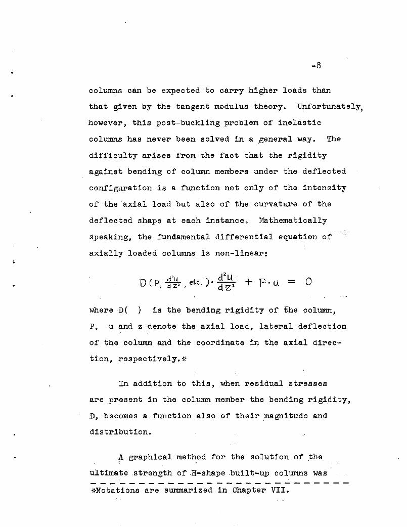
deflected shape at each instance. Mathematically
speaking, the fundamental differential equation of
axially loaded columns is non-linear:
o
whereD( ) is the bending rigidity of the column,
P, u and z denote the axial load, lateral deflection
of the column and the coordinate in the axial direc-
tion, respectively.*
In addition to this, when residual stresses
are present in the column member the bending rigidity,
D, becomes a function also of their magnitude and
distribution.
~ graphical method for the solution of the
ultimate .strength ofH-shapebuilt-up columns was----------------------------~}Notations are summarized in Chapter VII.
.
-9
(15)presented by Fujita in 1956, including the effect
of residual stresses due to welding. The problem of
eccentrically loaded columns is of essentially the
same nature as the case of the post-buckling behaivor
of axially loaded columns. A solution of the maximum
load-carrying capacity of wide-flange beam-columns sub
jected to an axial thrust and end moments was obtained
by Galambos and Ketter(16) in 1959. Since these
particular solutions are not applicable to any other
shape of cross sectiqn in which the magnitude and the
distribution pattern of the residual stresses are
different, further studies are necessary in order to
visualize the true column behaviors until failure
occurs.
The ultimate strength of axially loaded columns
may be influenced not only by the residual stresses
but also by initial deflections of the member. From
a practical point of view, the necessary information
for column design is the maximum load carrying capacity
of the member with certain amounts of allowance for
the unavoidable initial deformations rather than the
strength of an ideally straight member which does not
exist in reality. Wilder and others(17) investigated
the effect of the initial deflection on H-shaped columns,

.
~lO
showing a remarkable decrease in the load carrying
capacity. If residual stresses are taken into account,
the reduction may be influenced in a different way,
depending upon the distribution pattern of the residual
stress or the slenderness ratio of the column. In
1956 Huber(18) investigated the effect of cold~straight
ening residual stress in a wide-flange shape on the
maximum column strength about its weak axis. He showed
that the secant formula is too safe for short columns
with a large eccentricity, whereas for some cases it·
will be unsafe as compared with the true situation.
It will be also interesting to investigate such cases
where a column member has counter-initial deflection-
the convex side of the initially deformed shape con
tains compressive residual stress due to cold-straight
ening -- so as to delay the initiation of yielding
under compression. This may improve the column strength
to a certain extent •
II. THE R MAL RES I D U A L
INS 0 LID C I R C U L A R
STRESSES
COLUMNS
.
When structural steels are subjected to the usual
quenching operations, two different types of stresses,
thermal stresses and transformation stresses, will be
produced. (4) If the strains arising during the cooling
period exceed the elastic limit of the steel which varies
distinctly depending upon the correspondingt~~perature,
at any instance, residual stresses will remain ~f~er com
plete cooling is reached. In general, such a formation
of residual stresses is mainly influenced by the :heating
temperature, the coolant used and the shape and s;1.ze of
the specimen. For those materials which arer~p~~ly
cooled down by water quenching, the thermal.res~d~al
stresses become of great importance. In this ch~pter
the problem of thermal residual stresses in solid; circular
cylinders of high strength steel will be studied,,,on the
basis of both theoretical and experimental investigations.
In addition to this, a comparison with residual. s~resses
for those materials which are air-cooled or stres~-
relieved in the final heat treatment will also be made.
11.1 GENERAL DESCRIPTION OF THE ANALYSIS
a) TemperatureDistribution
When a long circular steel cylinder (radius = R) of
-11

-12
initially uniform temperature To is submerged into water,
the temperature distribution (at co-ordinate r, and time
t) can be obtained by making the following assumptions~19)
(1) Cooling takes place polar-symmetrically.
(2) There is no variation in temperature along
the length of the cylinder.
(3) Thermal diffusivity, K, is independent of
temperature.
(4) Newton's cooling law holds.
•
00
T(f)~) = 2c \To L
i= /
(II-I)
whereD rJ :: R = non-dimensional co-ordinate
Ie .1.
7:= R~ = non-dimensional time parameter
C = constant depending upon the initial
temperature and radius of the cylind~r,
and the mils satisfy the equations;
)(I. = /, Z J .3 • - •• )
J o and J I being the Bessel function of order zero and one,
respectively.
~13
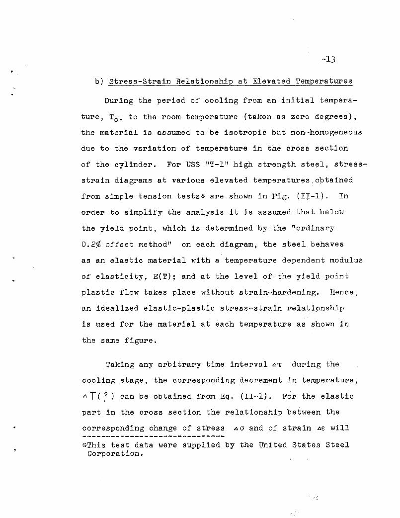
b) Stress-Strain Relationship at Elevated Temperatures
During the period of cooling from an initial tempera~
ture, To, to the room temperature (taken as zero degrees),
the material is assumed to be isotropic but non-homogeneous
due to the variation of temperature in the cross section
of the cylinder. For USS "T-I" high strength steel, stress-
strain diagrams at various elevated temperatur~~:obtained
from simple tension tests{~ are shown in Fig. (II-I). In
order to simplify the analysis it is assumed that below
the yield point, which is determined by the "ordinary
0.2% offset method" on each diagram, the steel. behaves
as an elastic material with a temperature dependent modulus
of elasticity, E(T); and at the level of the yield point
plastic flow takes place without strain-hardening. Hence,
an idealized elastic-plastic stress-strain rela~i9nship
is used for the material at each temperature as shown in
the same figure.
Taking any arbitrary time interval A~ during the
cooling stage, the corresponding decrement in temperature,
AT ( P) can be obtained from Eq. (II=I). For· the elastic;
part in the cross section the relationship between the
corresponding change of stress ~cr and of strain Ae will
~~This test data were supplied by the United States SteelCorporation.
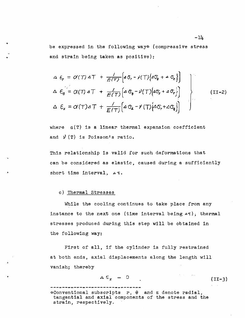
•be expressed in the following way-l~ (compressive stress
and strain being taken as positive):
A 6r = CX(T) aT + E(~) [od (jr - Y(T){LIO'q + A O"z J)A £8 = ()((T)I1T + E/T)[a{j9-Y(T){.1~+L1(jr}J
t::. t z =ex (T).1 T + E :Tj rA (j'z - y (T){4()r +-~(jeJ)
where aCT) is a linear thermal expansion coefficient
and V(T) is Poisson's ratio.
This relationship is valid for such deformations that
can be considered as elastic, caused during a sufficiently
short time interval, A't.
c) Thermal stresses
While the cooling continues to take place from any
instance to the next one (time interval being A1:), thermal
stresses produced during this step will be obtained in
the following way:
First of all, if the cylinder is fully restrained
at both ends, axial displacements along the length will
vanish; thereby
A € = 0z
.,~Conventional subscripts r, e and z denote radial,tangential and axi~l components of the stress and thestrain, respectively.
(II~3)
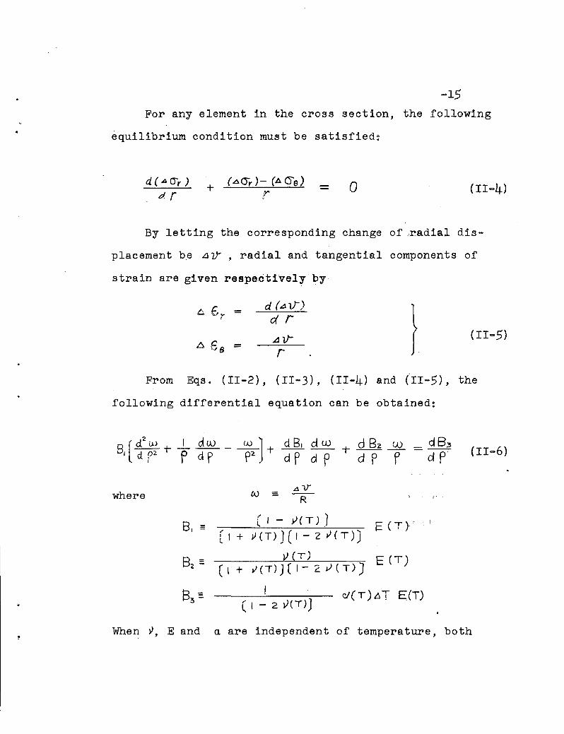
For any element in the cross section, the following
equilibrium condition must be satisfied:
d ( ..4 (Jr )
dr + a (II=4)
By letting the corresponding change of .radial dis-
placement be LlV , radial and tangential components of
strain are given respactively by
d (a if)
drA V"";
} (II-5)
From Eqs. (II-2), (II-3), (II-4) and (II-5), the
following differential equation can be obtained:
(II-6)
where fA) = L\lJ
R
8. :: [ , - y( T) .1 E (T r"[I + ~(T»)(1-2v(T)J
V (T)(I + v(T)](1-2 v (T)] E(T)
When ~, E and a are independent of temperature, both
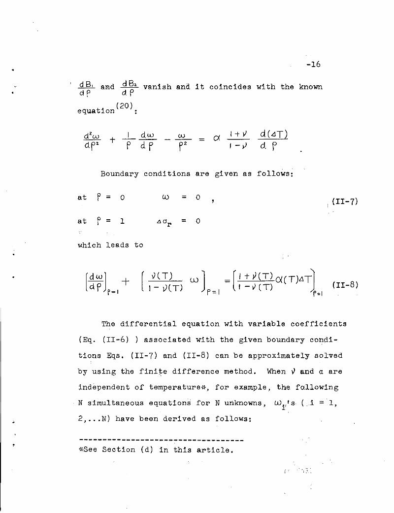
-16
dB. aNd dB2 vanish and it coincides with the knowndP dP
(20)equation :
T _1- dwPdf
UJ _ d. I + vI-y
Boundary conditions are given as follows:
at f = 0 W = 0 , (11-7)
at p = 1i = o
which leads to
[~WJ -tP p=1[
y( T)1- v( T)
w J = [ I + Y(T) ()( ( T)LlT'IF= I I - Y (T) )r=I
.
The differential equation with variable coefficients
(Eq. (11-6) ) associated with the given boundary condi
tions Eqs. (11-7) and (II-B) can be approximately solved
by using the fini~e difference method. When Y and a are
independent of temperature{~, for example, the fo:llowing
N simultaneous equations for N unknowns, Wi:'s; (. i = 1,
2, ... N) have been derived as follows:
-----------------------~-----------*See Section (d) in this article.

..
-17
U)~ _ I [ 2 i-I - ~ (C ~~ ,_ C ~- I ) ]
-t w. ·[-41, - + +-~-( C~+I- C~-I)]" It I-V ~ v
+ Wl+1 [ 2 i- + I + ~ (C~~I- C~-I)J
1+ Y t ( t+1 0 1- 1 T J=CXI=T N C~ ~Ttt,- '\",,;t ~ H
for i = 1,2,--~-1)
with
and
£.0 0 - 0 (11-9)
- ex
w._, [4NJ + (A","~4Nt4-~(~ +4)J
I +v [CN1"I,6 T - (4 + L
1- Y tI N+I N
- eN-I +cN+I)~T - eN-I JN N INN -C1 TN-I
where the subscript i of wand .6 T denotes those values
at p =i
i .N '
andt+1
C.\,
E ( PL+I)- E ( p\') ,
etc.
Since the first and the last equations contain only
two unknowns and the rest of them involve three unknowns
each, the solution can be easily obtained by eliminating
one unknown after the other.
From Eqs. ttl-2), (11-3) and (11-5), the incremental
axial stress produced in the fixed-end cylinder is given

• -18by the following formula:
b. 6" = E (T) (V d w + y w - (I +V) 0< L\TIz (ITV)(1-2V) d. P P J (II-IO)
However, the actual cylinder is free from the resultant
force in the axial direction; therefore the following
correction term
I
~~-f ,,~~ dA (- -21 6(5';' fd p)o
should be added to the axial stress given bi'~q~~~II-IO).
Thus, finally, the incremental stresses caused by cooling
during .t. 't will be obtained by the following formulae:
- ECT) ~ _ dw.J&._ ]L1 (Jr - (I+V)(1-2 VI) l(1 V) d P + V P (I+V)Q(6 T
L1 <:!e = E (T) [V dw +(I-Y)~-(I+~)()(~TI(I+V)(1-2Y) cd P PJ (II-II)
( ' I2 J A LJz . Fodp
'0
(i) Fully elastic case
Transient stresses at any instance of cooling will
be obtained as the summations of the incremental stresses
computed by Eq. (II-II), provided that the material

..-19
remains within an elastic limit depending upon the tempera-
ture at each location in question.
1:""'1::L L:::. l5 r,s,z'1:"= 0
(IL.-12)
(ii) Elastic-plastic case
Applying Mises' condition as the criterion of yielding
at various temperatures, the material will remain elastic
if
where
< I3
cr; (T)
(II-14)
However, when the value of J2
{T), which is computed by
using the stress components based upon Eq. (II-12),exceeds
I zthe value of '3 0; (T) ,yielding takes place in such
regions and a correction for the stresses must be made
in order to get the actual stress distribution. It is
assumed that during a time interval A't, the increment
of each stress component and (A a )z p
.. in the plastic range is proportional .to that of the elas
tiDally computed stress component of Eq. (II-II). (See
~20
Appendix A) Namely,
(Ll (je)p _ (A O'z)p
4 (Je A (j"z
e
These incremental stresses,
( A (J) thus assumed, satisfy the boundary condition andz p
the equilibrium condition of a small element, because
and A.(JZ
fulfill all these requirements.
Then, in the plastic region, the transient stress com-
ponents at 't = 't2 can be expressed in terms of those
values at the preceding step at 't = 'tl ('t2 - 't1 = A't)
and the plastic stress increments:
c;.,e,z (1:"= 't2) (II-15)
Since in the plastic region, when 't = 't2 ' the yield
condition must be satisfied,
Io
the following relationship is obtained from Eqs. (II-14)
and (II-15).
{II-16)
-21
where
"+(cre - ()z {~1;~~ ()e - 6()z) + (ITz - ITr- ~='t"~.6 Oz - ~ crr )J
Hence the proportional factor, e, is given as follows:
As a result of this correction for the incremental
stresses in the plastic range it becomes necessary to
redistribute the stresses in the elastic range so as to
maintain the equilIbrium of the whole body. For the con-
venience of the discussion, the incremental correction
stresses, A<1r 'e,z
as follows:
in the plastic range will be defined
/\ () - (.6 () r, e, z)p - !::. (Jr.,9,'Z~ r, e 1;Z
The resultant forces of the incremental correction stresses

-22
in both tangential and axial directions, Ga, and Qzare given respectively by
Qe = \ 6 ITa d r( PIQ.s'ti.C ione )
Qz = ~ 6 ()z' (211" r)· d r( Plo..sttc 3one)
The radial component AOr which vanishes at the elastic-
plastic boundary (e = 1) has no influence on the elastic
region. When the inner part of the cross section is
plastic and the outer part remains elastic (the boundary
at f = fe ), the average stresses to be corrected in the
elastic region are as follows:
o
R- re
Pe ..{o (1- e}A (Je·dp
1- Pe (II-19)
On the other hand, if the inner part is elastic and the
outside portion becomes plastic, then

I
lee ( I - e).Ll (je dPPe
-23
(II-19 t )
I
2 JeJ I - e)- A Oz . F· dPPe2
Finally, the transient stresses in the elastic range,
when ~ = ~2' are given by the following forms:
(II-20)
This process of computation will be continued until
the temp~rature of cylinder becomes uniformly equal to
zero. When time approaches infinity (~~oo) the residual
stresses are given by the limiting values of Eqs. (II-15)
or (II-20), depending upon either plastic or elastic
regions in the cross section.
d) Numerical Solution
The successive approximation method described in
the foregoing articles will be applied to the calculation
of the thermal transient and residual stresses in a water-

,..
·quenched high strength steel cylinder whichis..s.ubjected
to a sudden cooling from a uniform initial temperature
The temperature distribution in the cylinder is com
puted by Eq. (II-I) with the constant c = 4.5, which is
taken from experimental data given in the Ref. (6). Figure
11-2 illustrates the results for several values of the
time parameter,
By using the finite difference method with N= 10,
the U) 's are obtained from Eq. (11-9) for each incremen-n
tal time interval 6~. The appropriate E(T)'s.asfunction
of the temperature are taken from Fig. II-lb. In this
numerical computation it is assumed that the linear co
efficient of thermal expansion a is 7.74 x 10⁻⁶ inches
per inch per degree F throughout the whole range of tempera-
tures according to the results of experimental measure
ments(21). It is also assumed that :) = 0.3.
After obtaining the incremental stresses AO '8'r zfrom Eq. (11-10) and summing up these stresses, the
plastic check is performed at every stage of the computa
tion. Then the proper correction is made for.·elastic-
plastic cases where it is required. This step-by-step
process is repeated by evaluating the transient stresses
,•
·-25
at any instance 't, a typical result being shown in Fig .
II-3o
II.2
Finally when 't = 00 , the residual stresses
arid a are obtained as demonstrated in Fig. II-4 .z
EXPERIMENTAL INVESTIGATION
Residual stress measurements were carried 01lt on
2-3/4 inch diameter specimens of USS "T-I" Steel round
bars which were subjected to such final heat treatments
as quenching, air-cooling or stress-relieving. (22)
Since in circular cylindrical bars the resJdual
stresses resulting from heat treatment can be.:.assnmed to
have a distribution pattern of polar symmetry, Sach's
method is regarded as a suitable way for the measurement
of the triaxial residual stresses. (3) It should be
pointed out, however, that the ordinary boring-out
operation might cause yielding of the material a~jacent
to the drilled layer due to the heat generated. and there-
by may introduce unexpected influences on the strain
measurements. Such influences can be considered ~ocal
effects and safely ignored only if the strain rea~ings
are made on surfaces sufficiently removed from t~e bored
layer. They do become serious when the drilling ;Layer
approaches the outer surface where the strain gages are
attached. In-order to avoid these unfavorable conditions

•
,<
.
~26
and to obtain the complete residual stress pattern inc lud-
ing the outer part of the cross section, which contributes
most to the bending rigidity of the member and thereby to
its column strength, the so-called "combined method" (5)
together with the "boring-out method" was used in this
series of experiments. Two test specimens taken"from
originally identical material were measured by these two
different methods. The results obtained from.these indepen-
dent tests were checked against each other in that region
of the cross section where both methods were applied.. .'
As can be seen from the derivation of Sach's equation,
if only the boring-out method be used, the equilibrium
condition of resulting forces over the entire cross section
is always satisfied regardless of whether the measured
magnitude and distribution of residual stresses is correct
or not. Consequently, the equilibrium condition is not
sufficient to check the test results. If, however, two
independent processes such as the boring-out method and
the combined method are used on two specimens taken from
identical material, it is then possible to perfo~ the
equilibrium check in the final results of the residual
stress distribution. The difference between the computed
tensile and compressive resultant forces were in all cases
of this series less than five percent.

•
t.
-27The- results of test on a quenched material"are shown
in Fig'. II-4 and are compared with the theoretical
values obtained by the analytical method presented in the
previous art-icla. Their' correlation is satisfactory.
In addition maasured residual stresses for an air-
cooled and a stress-relieved material are shown in Figs.
II-5a and II-5b. There can be seen a considerable
decrease in the magnitude of residual stresses from the
one observed in the quenched material •
-- t
"
III. RES I D U A L STRESSES CAUSED
B Y THE COL D - S T R A I G H TEN I N G 0 F
COLUMNS
Rolled sections are usually straightened by such
operations as cold-bending, gagging, rotarizing, etc.
Since these operations involve plastic deformations of
the material, residual stresses will be produced in the
column members due to straightening. In this chapter,
the residual stresses caused by cold-bendin~ in round
columns will be investigated theoretically and experi
mentally.
III. 1 DEFLECTIONS AND RESIDUAL STRESSES
a) Deflection Analysis of a Beam with Circular Cross
Section
Through the cold-bending operation an initially
curved column member is straightened by an application
of loading which produces the same amount of permanent
deformations in the reverse direction as the original
deformation. A preparation of the load-deflection curve
for a given member under cold-bending will ther~fore
provide a reliable guide for the prediction of. the re
quired maximum load. This is especially true when the
-28

• -29
necessary and sufficient amount of the load is close to
the full plastic load of the member, because an applica
tion of excessive load might produce aplastic hinge in
the beam.
. (23)Using the simple plastic theory applied to the
problem of the flexure of beams with circular cross section,
the internal bending moment, M and the curvature, 56 for an
elastic-plastic cross section are given by the following
equations:
f (eo)
3 (-.IL - e +_1- s/n 4 eo) + .5/I1~&o·8 cos 80 2 0 4
(III-I)
(III-2)
where, eo defines the boundary between elastic and plastic
region in the cross section and ~ is the full plastic
moment of the beam. (See Fig. III-laJ
A simply supported beam shown in Fig. III-Ib is sub-
jected to a symmetric two-point loading, each load p
being at a distance I from the end of the beam. Let
z = Zo be the boundary between the fully elastic part
and the elastic-plastic part of the beam. The bending
moment due to the load p is

~.
p . z ( for o~ z ~ Q ) }
l~Z~~)
~30
(III-3)
where Mo is the uniform moment in the middle, hence
Mo = p • .Q •
Since the internal moment M is equal to the external
one, Eq. (III-I) andEq. (III-3) lead to
z ~P • fc So) ( fo r Zo <z ~ .t):. (III-4)
.~
•
From Eqs. (I1I-2), (III-3) and (III-4),
P F (') ) ( for z.P~ ~)}(lR) (III-5)t- (~) ( for ~ ~ Z ~2)
where ) r .z- M p
~tvlo-Mr·
I (-IF (~ ) = cos ( f' ('~ )J , J, (3) being the inverse
function of f("5) given byEq. (III-I).
Then the deflection, u, of the beam must satisfy
the following differential equations:
. ..) ;
"
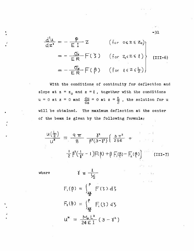
-31
d\A. 'f> Z ( fa r o~ Z ~ zo)-dz2 E I
Q\J F( ~) ( for zo~z~ t)- (111-6)ER
0,:1 Fe ~) ( for t~Z~~)- ER
With the conditions of continuity for deflection and
slope at z = Zo and z =i, together with the conditions
u = 0 at z = 0 and du = 0 at z = L , the solution for udz 2
will be obtained. The maximum deflection at the center
of the beam is given by the following formula:
lA(t-)u*
q-rr8
..•
where ~t
-~
F,(~) - \~ FC's)d'>-16
F2 (~)p
-L~ F; Cs) d')-
16
u* M p L2
( 3 - 02. )24 E I
. (111-7)
•
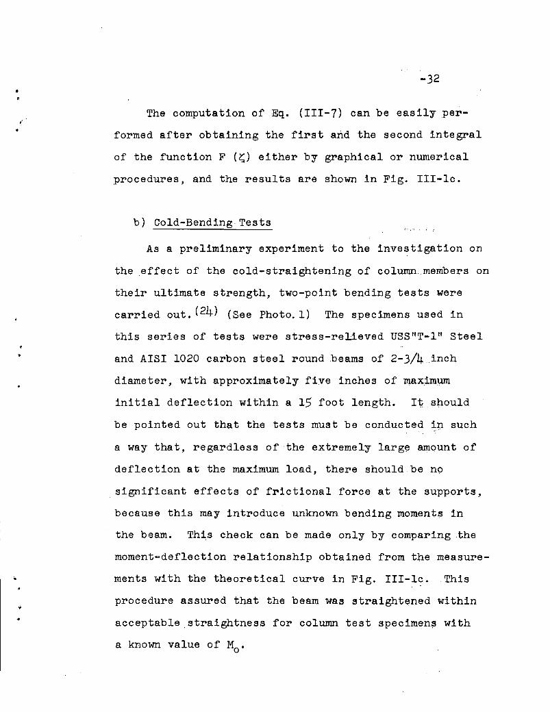
-32
The computation ofEq. (111-7) can be easily per
formed after obtaining the first and the second integral
of the function F (~) either by graphical or numerical
procedures, and the results are shown in Fig. III-Ie.
b) Cold-Bending Tests
As a preliminary experiment to the investigation on
the effect of the cold-straightening of column. members on
their ultimate strength, two-point bending tests were
carried out. (24) (See Photo. 1) The specimens used in
this series of tests were stress-relieved USS"T-l" Steel
and AISI 1020 carbon steel round beams of 2-3/4_.inch
diameter, with approximately five inches of maximum
initial deflection within a 15 foot length. It.should
be pointed out that the tests must be conducted i,p such
a way that, regardless of the extremely larg~ amqunt of
deflection at the maximum load, there should be nq
. significant effects of frictional force at the supports,
because this may introduce unknown bending moment$ in
the beam. This check can be made only by comparing the
moment-deflection relationship obtained from the measure
ments with the theoretical curve in Fig. III-l~. This
procedure assured that the beam was straightened within
acceptable ,straightness for column test specimens with
a known value of Mo.

L-33
c) Residual stress
. The residual stress remaining in the specimen after
cold-bending can be obtained as the sum of the stress
caused by the loading at the maximum moment Mo ' and the
stress which corresponds to the unloading process, assuming
elastic behavior at unloading. From Eqs. (III-I) and
(111-2), the axial residual stress, crz(~) is given by the
following equations:
163rr
where
1631f
~
R
(for FC1p)SS ~ .. I )
...
Figure (111-2) indicates that the residual stress
due to cold-bending has its maximum value at the extreme
fiber of the cross section when MO(=~)~O.979, and ifMp
MO ( 1M: =~)~O.979 the maximum value occurs at ~ = --=---~p F(~)

•
_t'
.-
-34
111.2 DEVELOPMENT OF THE "MODIFIED BORING-OUT METHOD"
As has been discussed in the preceding chapter, the
residual stresses in a solid circular column are classified
into two parts; (1) residual stresses due to the heat
treatment of the material, the distribution of which can
be considered as polar symmetric, and (2) residual stresses
caused by cold-bending which have an anti-symmetric distri-
bution with respect to the bending axis as shown +n Eq.
(111-8). In general, these two kinds of stresses are
coexisting in the specimen taken out from a cold-straightened
member. For beams with rectangular or H-shaped cross
section which contained uniaxial cooling resi,<iual<stresses
and then were subjected to cold-bending, a gra~hical method
for the computation of the formation of the final residual
stress was proposed by Huber. (18) In the case of_a
circular cross section, however, the residual str~ss due
to heat treatment is in a triaxial state; therefore an
analytical method of calculation for the cold-bending
residual stress, including the effect of the pre-existing
residual stresses, becomes quite involved.
On the other hand, it is also a difficult problem
to measure experimentally these residual stresses in
solid circular members. Since the ordinary "boring-out
method" presupposes polar symmetric distributions of the

.'i
-35
residual stresses, it is not applicable any more to the
present case.
The "modified boring-out method" suggested by Lam
bert(2) seems a reasonable approach to this problem,
because the use of this method makes it possible to
separate the residual stresses into a symmetr'ic and an
anti-symmetric part.
The strains, Ei , which are released by successive
boring~out sequences and are measured at four positions
of the outside sur{ace of the specimen, will be decom
posed into a symmetric set Eo and an anti-symmetric set
Ei • (See Fig. 1II-3a)
s·f., + (';'=1,2,3&4)
I
4
The symmetric part can be converted into a symmetric
set of residual stresses by Sachts equations. (See Art.
II-2) The anti-symmetric part of strain in the axial
direction will be related to the anti-symmetric residual
stress in the following manner:
When the specimen is drilled out from inside up to
a radius r, the bending moment M (r) which is associated

-36
with the anti-symmetric residual stress O'z{x) of the re
moved part can be expressed in the following equation:
Men -= -4 ( <Yz(X)' x - j rZ- x' '·d x
o(III-9)
.•
The remainder of the cross section will ,be strained
by this removal of the stressed material, which, in turn,
is equivalent to an application of a moment-Mer) to the
specimen inducing a longitudinal strain ofe = ~ (e3- e l )
at a distance R from the neutral axis. Assuming that the
ordinary beam theory holds in this case, this concept
leads to the following expression:I
where,
Mer)· RE IC r)
.. (III-IO)
I (r)1r
4
Using non-dimensional notations, Eqs. (III-9-) and (III-IO)
will result in a Volterra's integral equation of the first
kind:
where
If
SCP) - a;(~)' KCPi ~)'d3o
(III-II)
. . .~
\

•"
.1
•.•
-37
k(f;~)-VP-~
Since K (P;s ) is finite and continuous for any value.-,-
of p and S, hence is called a regular kernel, this equa-
tion can be solved by expanding the right hand term into
a mean value of the integral. (25) Using MacLaurints expan
sion method, the residual stress in question, at s~;(i- ~)h
is obtained successively from i = 1 to i =N,bythe follow
ing formula, N being the number of divisions for s : (See
Appendix B). . I
~~~~) -t a~ .K(t,h ij-t h)'~ (j-th)Oz (i,-t h ) = .1-1 _ _ . (111-12)
0( ~ j, . K(Lh ; ~- t h ) , (t =IJ 2 .... t-J )
where, aij are MacLaurin's coefficients given in Appen
dix C and h = 1N

.. -38
From a practical point of view, it will be preferable
to divide at first the whole region of s (from s = 0 to
s = 1) into few parts, and then subdivide them into N
d~visiops,e.g. N =5, by applying a similar formula as
Eq. (111-12).
Figure 1II-3c shows an example of the. results which
were. obtained by this methoq., ,.1l:3ing experimental data of
-E (~ig~ 1II-3b) measured from a cold-bent beam specimen.
The symmetric part of the residual stresses was also
obtained from the same test specimen by the ordinary
Sac'h'.s method, and is given in Fig. III-3d. It Q~n be
seen that almost the same amount of residual stresses
was found from this specimen as from the one measured
before cold-bending. It is of course true that. in steel
beams, which initially contained residual stresses due
to heat treatment and then were subjected toa cold-bend-
ing operation, the final residual stress is not ~qual to
the one obtained by a simple superposition of tlll'0 stresses,
i.e. one due to heat treatment and another one.co~puted
by Eq. (111-8). In other words, the anti-symmetr~c part
of. the final residual stresses obtained by this "modified
boring-out method", theoretically speaking, do~snot
correspond to the one which had been produced by cold
bending only without including the pre-existing stresses.
However, if the pre-existing stresses are comparatively
..
-39
lower than the ones caused by cold-bending, the influence
of the presence of the former becomes minor. This fact
is indicated in Fig. 1II-3c.
111.3 "BEAM DISSECTION METHOD"
In the preceding article, the modified bor+ng-out
method has been introduced for the measurement of residual
stresses of an arbitrary distribution pattern in a solid
circular cylinder. This method, which takes into account
the triaxiality of residual stresses, is quite general,
complete and useful, but it requires many SR-4 strain
gages and involves a great amount of work to co~plete
the successive drillings. Therefore it is wqrtnwhile to
develop a simpler method of residual stress measurement
which furnishes a practical accuracy. If one neglects
the effect of both tangential and radial compone~~s of
residual stress in a solid cylinder, the beam dissection
method would be a sui table way of finding_the magnitude
and distribution of axial residual stresses, provided
that their variation is only in one direction (i.e.
perpendicular to the axis of cold-bending). The.change
of length within a certain gage length is measured
before and after cutting and slicing the specimen into
several narrow strips. (Fig. 1II-4a) Residual stresses

•
't-o
•
-40
in 2-3/4 inch round "T-I" Steel obtained by this method
are shown in Fig. 1II-4b. Even though this method is
an approximate one, satisfactory results for information
on column strength were obtained from several tests. (24)

•
IV. I N E LAS TIC B U C K LIN G S T R E~N G T H
o F C I R C -U L A R COLUMNS
0.
..
IV.l COLUMN STRENGTH AND THE "EQUIVALENT RESIDUAL STRESS It
The influence of residual stress on the inelastic
buckling strength of steel .. columns has been studied by- ... - --
several investigators(1~l(18) since.~SgOOd,(lO) Yang and
others (11) presented their papers .. c~~cerning_ a general
theory of this problem. As the column strength is
primarily dependent on the m~gnttude and the distribu
tion of· residual stres8es, it is necessary to, calculate
the buckiing strength for eachce..se of a given shape of
cross section with a known patt~rn of residual stress.
For steel columns of wide flange shape or rectangular
cross section, reasonable solutions were obtained'--
theoretically, and were checked with a large number of
test results. (12) The residual stress in these columns,
is uniaxial so that the total stress at any fiber in
the cross section can be obtained simply as the sum of
the residual stress and the imposed stress due to load-
ing.
In the case of solid cireul~r columns, however,
it has been found that the residtial stresses due to
heat treatment are in a triaxiafstate, where the axial
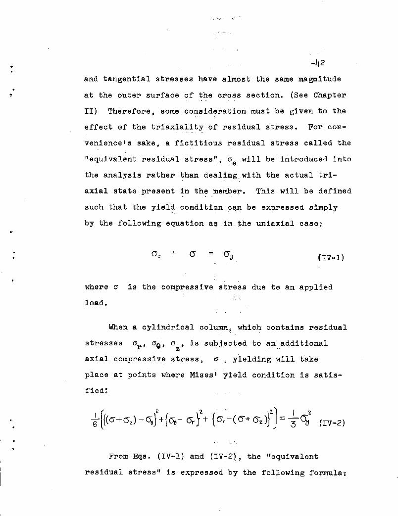
"-42
and tangential stresses have almost the same magnitude
at the outer surface of the cross section. (See Chapter
II) Therefore, some consideration must be given to the
effect of the triaxiality of residual stress. For con-
venience1s sake, a fictitious residual stress called the
"equivalent residual stress~', O'e will be introduced into
the analysis rather than dealing wi th the actual tri
axial state present in the member. This will be defined
such that the yield condition q!ilf be expressed simply
by the following'equation as in the uniaxial case:
= (IV-I)
..,
where (J is the compressive stress due to an applied
load.
When a cylindrical column, which contains residual
stresses O'r' 0'0' 0' , is subjected to an additionalz 'axial compressive stress, a, yielding will take
place at points where Mises l yield condition is satis-
fied:
From Eqs. (IV-I) and (IV-2), the "equivalent
residual stress" is expressed by the following formula:
-43
(IV-3)
..
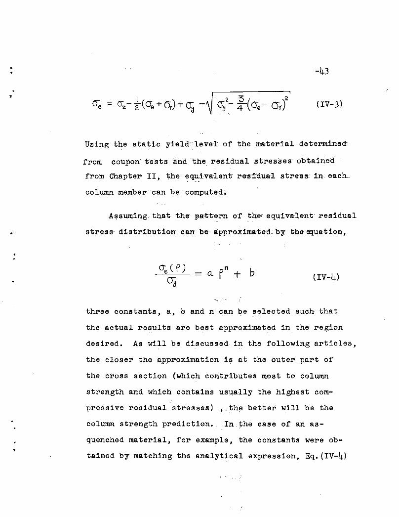
Using the static yield: level of the ma:tertal determine'd::
from coupon' tests and ,the residual stresses obtained
from Chapter II, the' equiva.Tent re's'i'dual stress~ in each
column member can be"computed'~
Assuming. that the pattern of the i equivalent·· residual
stress di-s.tribution';can be approximated, by thsequation,
•a. pn + b (IV-4)
three constants, a, band n can qe selected such that
the actual results aI'e best approximated in the region
desired. As will be discussed in the following articles,
the closer the approximation is at the outer part of
the cross section (which contributes most to column
strength and which contains usually the highest com
pressive residual stresses) ,_th~ better will be the
column strength prediction.,. . In.1ihe case of an as-
quenched material, for example, the constants were ob-
tained by matching the analytical expression, Eq.(IV-4)
. j

....
•
-44
wi th the equivalent residual stress at p= 0.70, 0.95
and 1.00. The resulting constants were
a = 0.459
b = 0
n = 19.
Figure IV-l shows the comparison between the actual
equivalent residual stress distribution and this approxi m
mation, which is only valid for the outer part of the
cross section. A better result over the entire range
can be expected by assuming suitable formulae which
include also lower order terms with respect to F , in
addition to the cur~ent form given by 'Eq. (IV-4). How-
ever, as will be shown in Chapter V the effect of using
this more involved expression on the computation of the
ultimate strength of a column is 'negligible except for
very short columns. Because~columns of practical length
reach their maximum load before yielding in the cross
section penetrates into a region where P< 0.5 (approxi
mately); in this region the,magnitude of the equivalent
residual 'stress is usually 19W•.
IV.2 STRESS-STRAIN RELATIONSHIP AND STUB COLUMN TESTS
.. One of the most fundameratal;bases for the determina-
tion of the inelastic buckling strength of column members
•
-45
is the static stress-strain relationship of the material
in the inelastic range. This relationship can be ob
tained only by coupon tests which are conducted under
a controlled rate of strain. (26) For a high strengthl
steel, such as USS"T-I" Steel, the stress-strain curve
of a coupon test shows-a pronounced yield stress level,
and strain hardening can hardly,be observed until'. (22)
fracture takes place. I~other words, the ideal-
ized elastic-full~plasticstress-strain relationship
is a good approximation for such a high strength steel.
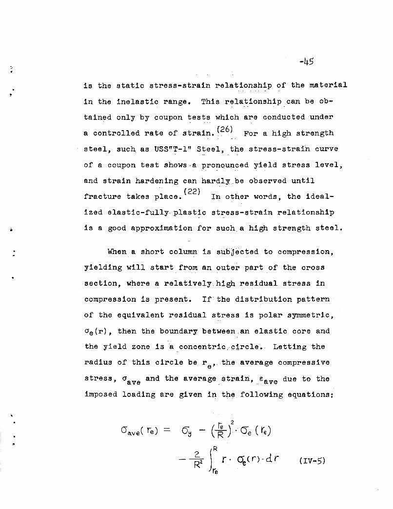
When a short column is sub~ected to compression,
yielding will start from an outer part of the cross
section, where a relatively high residual stress in
compression is present. If the distribution pattern'
of the equivalent residual stress is polar symmetric,
cre(r), then the boundary between ,an elastic core and
the yield zone is • concentric~~1rcle. Letting the
radius of this circle be r ,. ,the average compressivee
stress, crave and the averagestrairi, eave due to the
imposed loading are given in,tl:1~,following equations:
Ie 2O~ - (R)' Oe (re)
- ~2 JR r· ~(r) . d rre
(Iv-5)
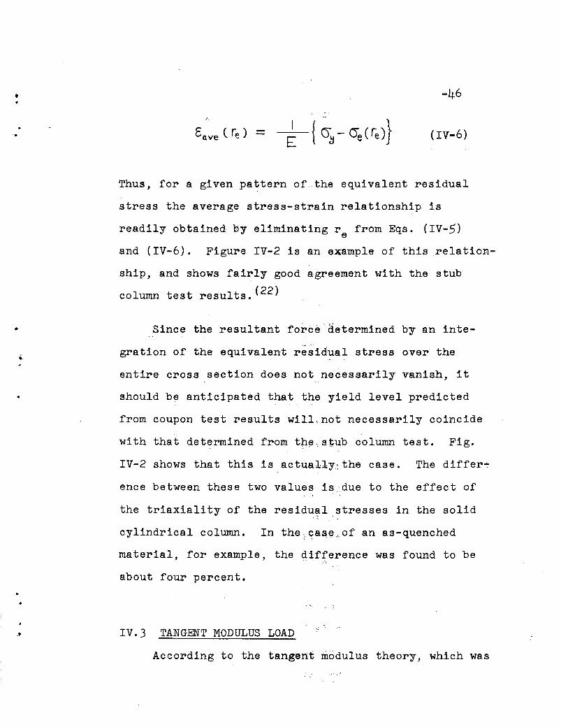
• -46/.
Go.ve ( re ) - (IV-6)
..
Thus, for a given pattern of the equivalent residual
stress the average stress-strain relationship is
readily obtained by eliminating r from Eqs. (IV-5). e
and (IV-6). Figure IV-2 is an example of this "relation-
ship, and shows fairly good agreement with the stub
column test results. (22)
Since the resultant force "determined by an inte
gration of the equivalent residual stress over the
entire cross section does not necessarily vanish, it
should be anticipated that the yield level predicted
from coupon test results will not necessarily coincide
with that determined from the;stl.l.b column test. Fig.
IV-2 shows that this is actually:the case. The differ~
ence between these two values is ,due to the effect of
the triaxiality of the residual stresses in the solid
cylindrical column. In the., ,?as~;.of an as-quenched
material, for example, the difference was found to be
about four percent •
IV.3 TANGENT MODULUS LOAD....,; .
According to the tangent modulus theory, which was

.. -47originally introduced by "Engesser, and was reconsidered
later by Shanley, the buckling load, P ,of acrcentrally loaded and perfectly straight column is given
by the so-called tangent modulus formula: (8)
"PerA
•
This formula presumes that the material is homogeneous
even in the inelastic range and that its stress-strain
characteristics are known.
If, however, residual stresses are present in a
column member which is compressed beyond the elastic._ '_ "_.'_ ~., ;_; I
limit, yielding will take place. at localized parts of
the cross section where the total stress is equal to
cr . thereafter, the column material becomes non-homoy'
geneous. When an idealized s:tI"~Ss-strain relationship
is assumed for the material and residual stresses are
taken into account, it has been shown that the follow[ng
formula for the buckling load, Per applies: (11)
•
PerA
whereEIe is the effective bending rigidity of the column.
•..
..
..
.>
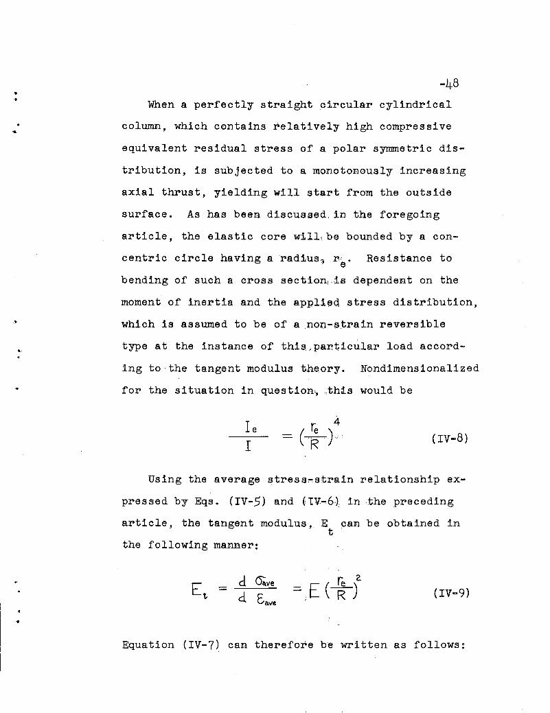
-48When a perfectly straight circular cylindrical
column, which contains relatively high compressive
equivalent residual stress of a polar symmetric dis-
tribution, is subjected to a monotonously increasing
axial thrust, yielding will start from the outside
surface. As has been discussed, in the foregoing
article, the elastic core w:tlL.be bounded by a con-
centric circle having a rad:tus~ reo Resistance to
bending of such a cross section, ,is dependent on the
moment of inertia and the appl1~d stress distribution,
which is assumed to be of a .non-strain reversible
type at the instance of this .. particular load accord-
ing to·the tangent modulus t.neory. Nondimensionalized
for the situation in question",this would be
IeI
(IV-8)
Using the average stress~strain relationship ex-
pressed by Eqs. (IV-5) and (tV-6~ in the preceding
article, the tangent modulus, E can be obtained int
the following manner:
..
d C4.ved Eave (IV-9)
Equation (IV-7) can therefore b~ written as follows:
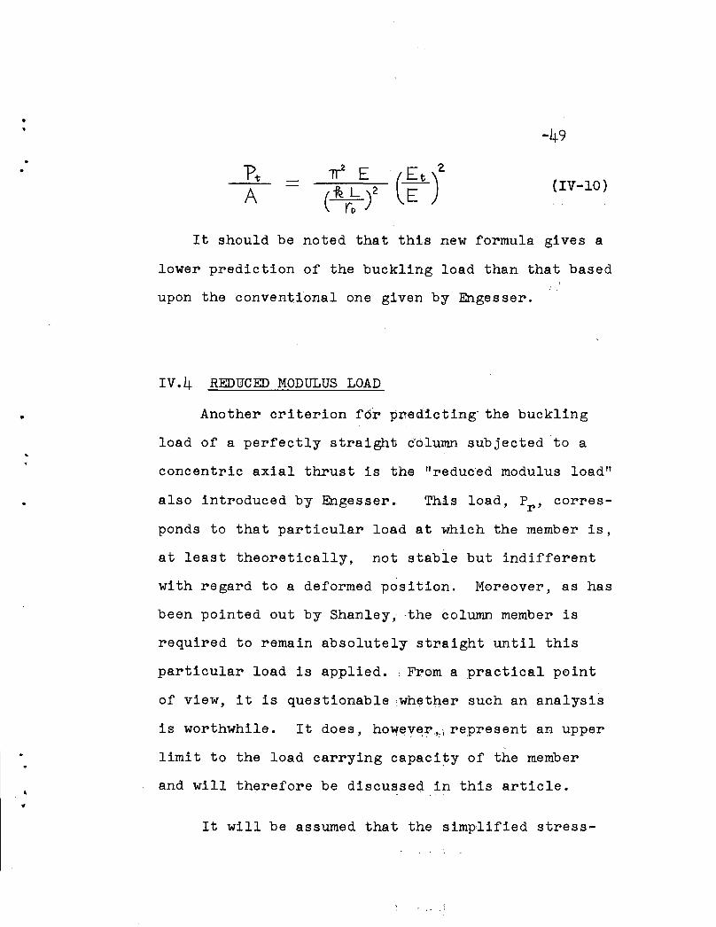
-49
(IV-lO)
It should be noted that this new formula gives a
lower prediction of the buckling load than that based
upon the conventional one given by Engesser.
•
IV.4 REDUCED MODULUS LOAD
Another criterion f6r predicting the buckling
load of a perfectly straight d'olumn subjected to a
concentric axial thrust is the "reduced modulus load"
also introduced by Engesser .. This load, Pr , corres-
ponds to that particular load at which the member is,
at least theoretically, not stable but indifferent
with regard to a deformed position. Moreover, as has
been pointed out by Shanley,-the column member is
required to remain absolutely stnaight until this
particUlar load is applied. . From a practical point
of view, it is questionablewh~t4ersuch an analysis
is worthwhile. It does, hOVfev~r'.'i represent an upper
limit to the load carrying capacity of the member
and will therefore be discussed in this article.
It will be assumed that the simplified stress-
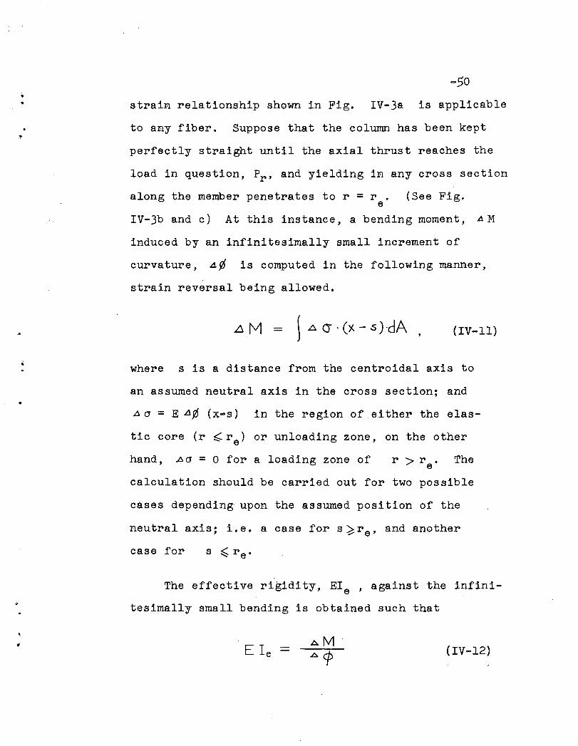
•• strain relationship shown in Fig. IV-3a is applicable
to any fiber. Suppose that the column has been kept
perfectly straight until the axial thrust reaches the
load in question, Pr , and yielding in any cross section
along the member penetrates to r = r .e
(See Fig.
IV-3b and c) At this instance, a bending moment, AM
induced by an infinitesimally small increment of
curvature, .4 ¢ is computed in the following manner,
strain reversal being allowed.
~ 4 (j . (X - s )·dA (IV-II)
where s is a distance from the centroidal axis to
an assumed neutral axis in the cross section; and
~ (J = E A¢ (x·s) in the region of. ei ther the elas-
tic core (r ~re) or unloading zone, on the other
hand, ~(J = 0 for a loading zone of r > r. Thee
calculation should be carried out for two possible
cases depending upon the assumed position of the
neutral axis; 1. e. a case for s ~ r e' and another
case for
The effective rigidity, Ele ' against the infini
tesimally small bending is obtained such that
E Ie (IV-12)
•
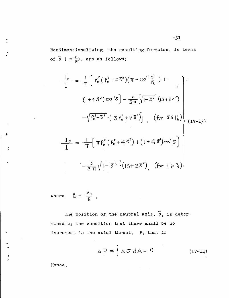
-51
Nondimensionalizing, the resulting formulae, in terms
- sof s ( =R)' are as follows:
••
IeI
IeI
where
(IV-13)
The position of the neutral axis, s, is deter-
mined by the condition that there shall be no
increment in the axial thrust, P, that is
\ Do cr- dA = a
Hence,

•1>
-52
P -2 ( -I.s '\ I AI -z I ( -2)- 'e S S/17 Ct7J ~) - 3'V I - S . 2 + oS
- -1_+ S cos S o)
(for s ~ Fe ) (IV-15)
•
..
0 2- I ~ - 2 I ( -2) - -I - 01f I ~ S - ~ I - S ,2 +.s. +..s. cpS s'= )
These equations can be solved graphically for given
values of Fe' and the results are shown in Fig.
IV-4·
By using the results, Ie will be obtainedr
from Eq. (IV-13). In Fig. IV-5, it can be seen that
the effec tive bendingr.i.gid·i ty, Ie., based upon theI
reduced modulus concept is approximately proportional
re tto (If), whereas that corresponding to the tangent
modulus theory is proportional toe reO )4. Therefore,..- _. ......_..- ... ', -- __ R
by Eqs. (IV-7) and (IV-9) it follows that the reduced
modulus load, Pr , can be expressed as follows:
:'
~. - rr2 E
-; ."
(IV-16)
..
..
-53
It is an interesting fact that the conventional
formula for buckling load which has been regarded as
the "tangent modulus load" is found, by the considera
tion of the influence of residual stresses, to be
approximately equal to the "reduced modulus load" in
the case of circular columns, of which the l! true·.
tangent modulus load" is given by Eq. (IV-IO).
It has also been found that the difference be-
tween the two values of these buckling loads for an
as-quenched column, for example, is less than seven
percent. (22)
"
V. U L TIM ATE S T R ENG THO F
C IRe U L ARC 0 L U M N S
V.I GENERAL
In the preceding chapter, the behavior of perfectly
straight columns, containing residual stresses of polar
symmetry and subjected to a concentric axial thrust,
was considered. The discussion was limited to the
buckling problem of such members which have remained
in the laterally undeformed position until a particular
critical load, either the tangent modulus load or the
reduced modulus load depending upon the criterion for
buckling, was reached. On the one hand, at the tan
gent modulus load the column starts to bend only if
the applied load is increased. It therefore represents
a "stable" equilibrium configuration with the member
being capable of carrying additional load. The reduced
modulus load, on the other hand, represents an upper
limit to the maximum load which can never be reached
unless some constraints against lateral deflections
are provided.
A determination of the true ultimate strength of
columns is a post-buckling problem in the inelastic
range. A general analytical solution to this problem
-54
•
-55is extremely difficult to obtain. Duberg and Wilder
presented a paper on the behavior of inelastic columns
by using a model of a "spring-supported column" and
an "idealized H-section column" with an assumed stress-
t i di f th material. (14) Th h d th ts ra n agram 0 e ey s owe a
an initially straight column can carry a certain amount
of load beyond that given by the tangent modulus theory,
the difference between these loads being dependent upon
the stress-strain relationship of the material. It
was concluded that for such materials, for which the
departure from the elastic curve is abrupt as in the
case of the high-strength aluminum or magnesium alloys,
the maximum load is only slightly above the tangent
modulus ioad.
However, the yield pattern in the cross section
and consequently thehending rigidity for inelastic
columns is a function not only of loads and curvatures
a teach ins,tance but it d'epends also on the magnitude
and distribution of residual stresse's which are
present in the members. It is therefore an unreal-
istic approach to investigate such a column behavior
in the inelastic range by calculating the benqing
rigidity of the partially yielded cross section by
using a stress-strain relationship of the material
based upon coupon test data. In this dissertation
•
..
•
-56a semi-graphical apprbach for obtaining a solution to
the ultimate load carrying capacity of circular columns
will be presented, taking into account the effect of
the residual stresses.
Generally speaking, this method of analysis should
be also applicable to a solution of the ultimate load
carryingcapaci ty of columns. which contain a non
symmetric, residual stress pattern or whiclt hav~ initial
deflectio,ns along the member. Those cases are of course'. ~
different from that described in the preceding paragraph
because the columns with a non-symmetric residual stress
pattern or with initial deflections (which may be called
"beam-columns"), have no bifurcation points on their
load-deflection curve. After buckling has taken place,
however, the situation of an initially straight column
with symmetric residual stresses is essentially the
same as the other ones, regardless of the history
prior to the buckling. Therefore, similarconsidera
tions will be followed for the development of the.,
solution to both cases; (a) for columns with a residual
stress of polar symmetry, and (b) for columns with an
anti-symmetric residual stress.
Although there might be some other factors which
cause a reduction in the ultimate carrying capacity
of concentrically loaded columns, the effect of initial
•
•
.:.57
(17)deflections of members will be of major significance.
For th~s reason, investigations on the combined effects
of these internal and external imperfections, that is
. '''residual stresses ll and lI out-of-straightness ll , will be
carried out.
The following assumptions and limitations are made:
(1) The material possesses the idealized elastic-fully
plastic type of stress-strain relationship. (See
Art. IV.2)
(2) Plane cross sections remain plane.
•
•
(3) Mises l yield condition defines the yielding of the
material. (See Art. IV-I)
(4) A simply supported column (the length of which is
equal to kL) is subjected to a concentrically
applied axial thrust.
(5) Lateral deflections of the column can be approxi-
mated by a cosine curve,
u(z) = d· COSt ~ ~ )
where d is the deflection at mid-length of the
column. Hence it follows that the curvature, ¢,
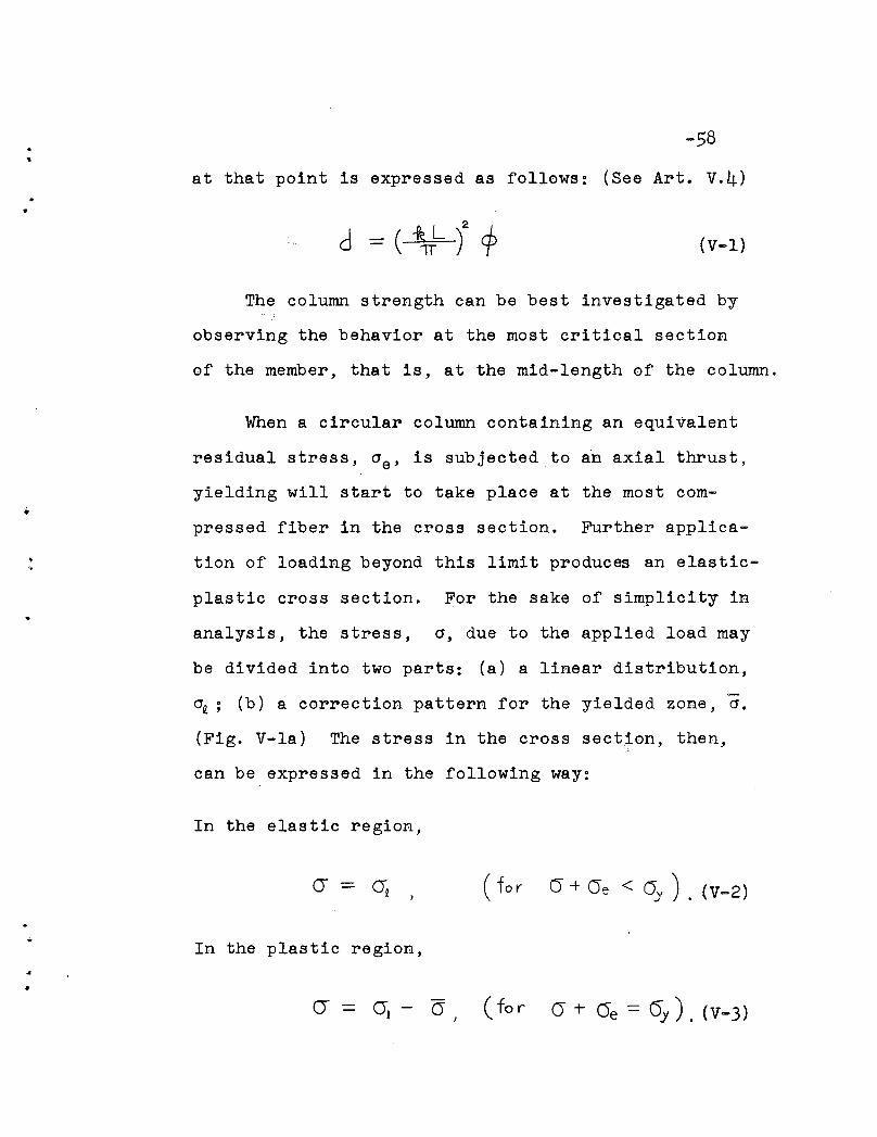
..-58
at that point is expressed as follows: (See Art. v.4)
d (V-I)
'4
The column strength can be best investigated by
observing the behavior at the most critical section
of the member, that is, at the mid-length of the column.
When a circular column containing an equivalent
residual stress, ae , is subjected to an axial thrust,
yielding will start to take place at the most com
pressed fiber in the cross section. Further applica
tion of loading beyond this limit produces an elastic
plastic cross section. For the sake of simplicity in
analysis, the stress, a, due to the applied load may
be divided into two parts: (a) a linear distribution,
~; (b) a correction pattern for the yielded zone, a.
(Fig. V-Ia) The stress in the cross section, then,
can be expressed in the following way:
In the elastic region,
( for 0 + Oe < 0)1 ) . (V-2)
In the plastic region,
0, - a ( fo r 0 + (Je
..
•
-59
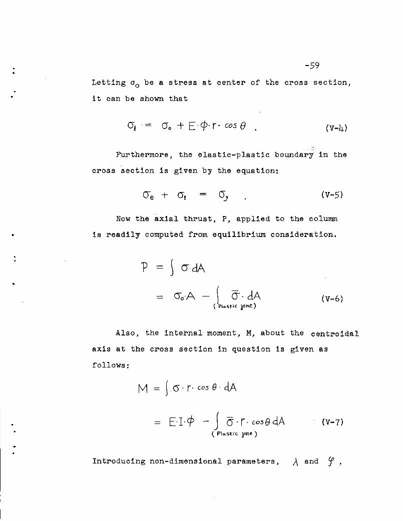
Letting 00 be a stress at center of the cross section,
it can be shown that
0 0 + E·ep· r· cos e (V-4)
Furthermore, the elastic-plastic boundary in the
cross section is given by the equation:
(V-5)
•
Now the axial thrust, P, applied to the column
is readily computed from equilibrium consideration•
,.•
..) erdA
()o,A - \ (J. dA( PI",stiC ~otle)
(V-6)
Also, the internal moment, M, about the centroidal
axis at the cross section in question is given as
follows:
tv1 } O· r· cos e. d.A
E-I'<P - J (J. r· cosG·clA( Plo-st,'c. aone )
Introducing non-dimensional parameters, A and 'f,

..-60
•defined as,
A - 'f - ER ¢OJ )
the elastic-plastic boundary (Eq. (V-5) ) is given by
II + Cf· f· (05 f) - I + ()e = aOJ (V-5 1 )
Similarly, P and M are given, by using Eqs.
and (V-4) , as follows:
(V-3)
...
= A - ~ f([AT<PPCOS e-1- ~;}r ·d.p·de. (V-61)(PIQ.stiC. lOne)
(V-7 1 )
iscr
e
cry
given, the elastic-plastic boundary is obtained as
If the pattern of equivalent residual stress,
..,
a sol1,ltion of Eq. (V-5 f ), and :Q.erewith, U (;\ , Cf) and
V (A, 'f) can be computed by Eqs.(V-6 f ) and (V-7 f ),
respectively.
•
-61
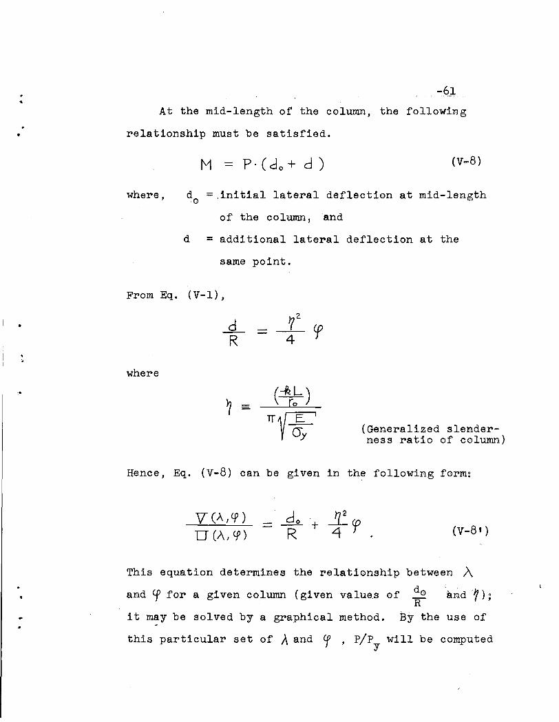
At the mid-length of the column, the following
relationship must be satisfied .
(v-8)
where, d =,initial lateral deflection at mid-lengtho
of the column ,and
d = additional lateral deflection at the
same point.
•
From Eq. (V-I),
-.9-_R
where
~z.
4
? - (~L)[0
(Generalized slenderness ratio of column)
Hence, Eq. (V-8) can be given in the following form:
do + £epR 4 .
between A
do and '1);R
By the use of
This equation determines the relationship
and Cf for a given column (given values of
it may be solved by a graphical method.
this particular set of }.. and Cf ' pIpY will be computed
,•
-62
from Eq. (V-6 t ), and thereby the load-deflection curves
can be obtained.
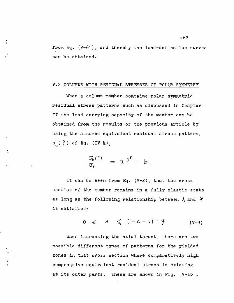
V.2 COLUMNS WITH RESIDUAL STRESSES OF POLAR SYMMETRY
When a column member contains polar symmetric
residual stress patterns such as discussed in Chapter
II the load carrying capacity of the member can be
obtained from the results of the previous article by
using the assumed equivalent residual stress pattern,
'~
no.p + b.
It can be seen from Eq. (V-2), that the cross
section of the member remains in a fully elastic state
as long as the following relationship between A and Cf
is satisfied:
o ~ ~ (1- a.. - b) - ep (V-9)
When increasing the axial thrust, there are two
possible different types of patterns for the yielded
zones in that cross section where comparatively high
compres,sive equivalent residual stress is existing
at its outer parts. These are shown in Fig. ,V-lb.
..
•
-63
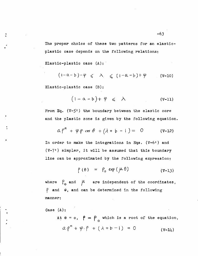
The proper choice of these two patterns for an elastic
,plastic case depends on the following relations:
Elastic-plastic case (A):
(I-Q-b)-ep < A ,(I-Q-b)+ep
Elastic-plastic case (B):
(V-IO)
(V-II)
From Eq. (V-5 t ) the boundary between the elastic core
and the plastic zone is given by the following equation •
•;.a· fn + cpo P0 c~s f) + (.A + b - I ) = 0 (V-12)
In order to make the integrations in Eqs. (V-6 t ) and
(V-7 t ) simpler, it will be assumed that this boundary
line can be approximated by the following expression:
Po exp (f- e) (V-13)
where p and U.o I are independent of the coordinates,
..
p and e, and can be determined in the following
manner:
Case (A):
Ate = 0, r = F0 which is a root of the equation,
aofn + <po P + (A + b - I) = 0 (v-14)
•..
•
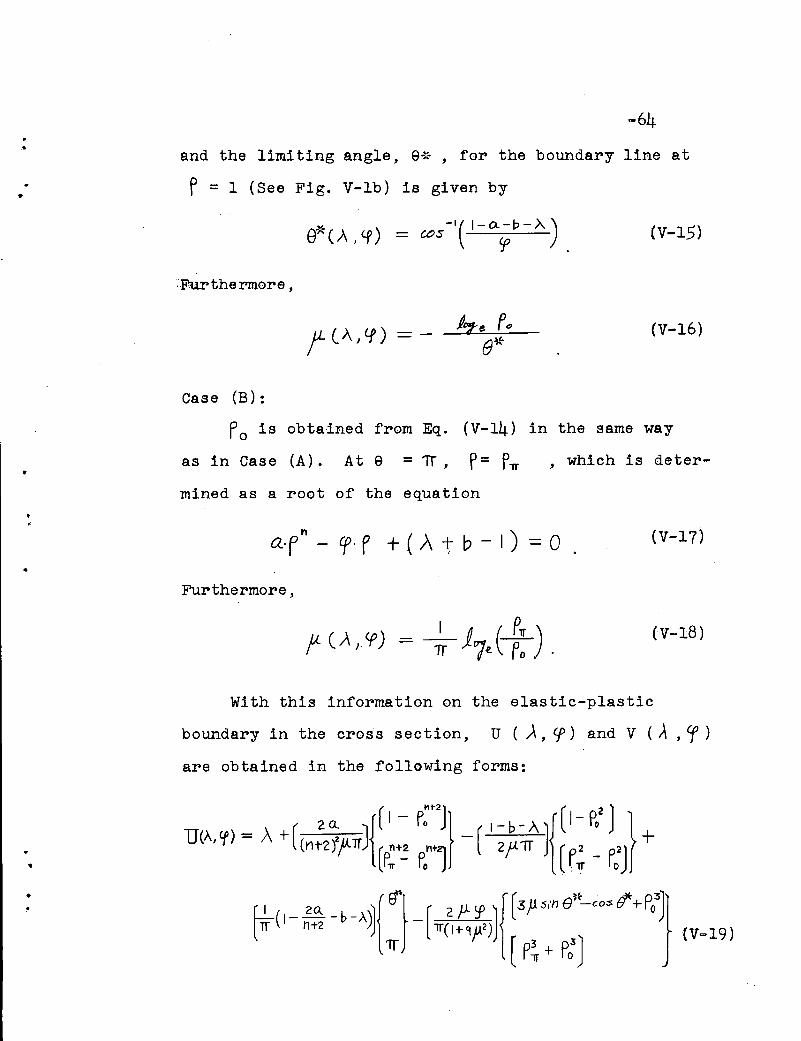
-64
and the limiting angle, EH~ , for the boundary line at
f = 1 (See Fig. V-lb) is given by
(v-15)
~--Furthermore,
(V-16)
Case (B):
Po is obtained from Eq. (V-14) in the same way
as in Case (A). At e = if, P= PlT , which is deter-
mined as a root of the equation••
a·Fn - Cf· f + ( A 1;- b - I) =0
Furthermore,
(V-17)
(V-18)
•
With this information on the elastic-plastic
boundary in the cross section, U ( A, Cf) and V (A , Cf )
are obtained in the following forms:
••-65
•
\
•(V-20)
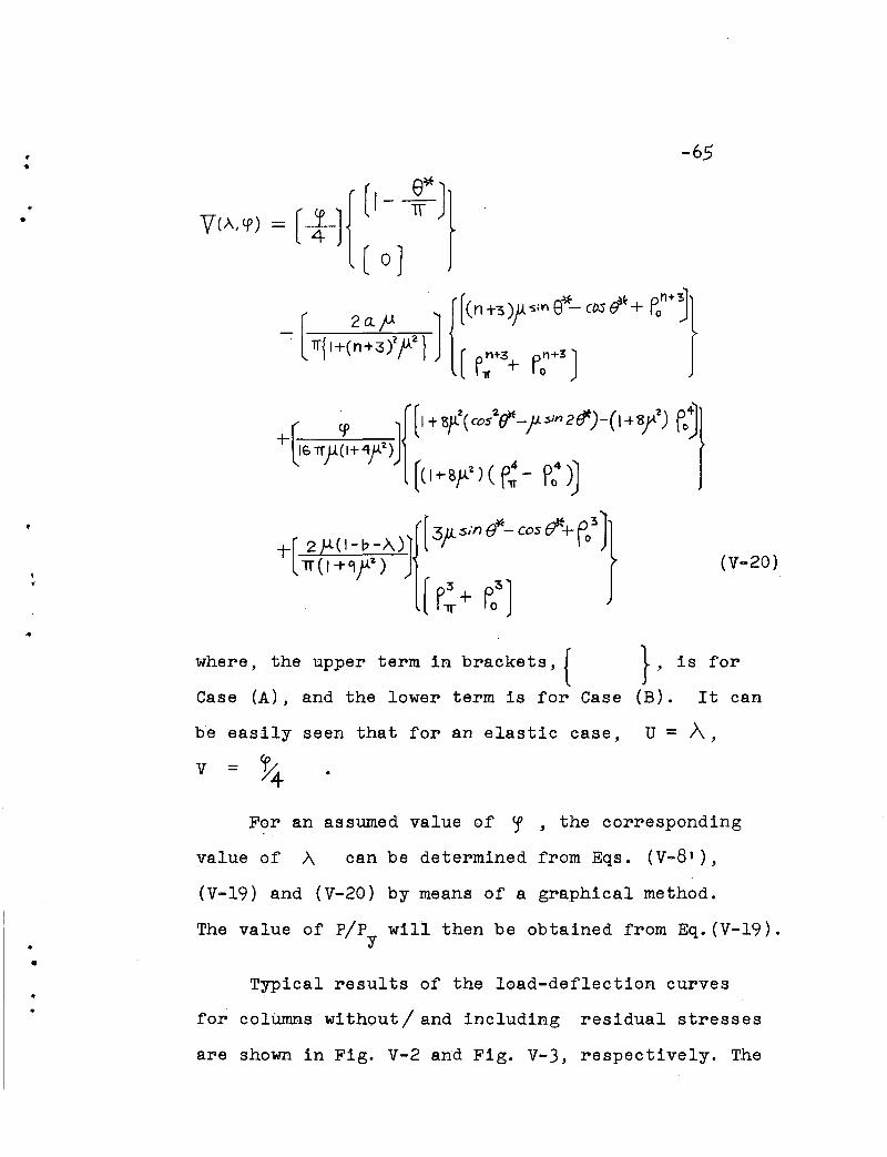
where, the upper term in brackets, {
Case (A), and the lower term is for Case
be easily seen that for an elastic case,
v = %
}, is for
(B). It can
U = A ,
•
•
For an assumed value of ~ , the corresponding
value of A can be determined from Eqs. (V-B'),
(V-19) and (V-20) by means of a graphical method.
The value of pip will then be obtained from Eq.(V-19).y
Typical results of the load-deflection curves
for columns without/ and including residual stresses
are shown in Fig. V-2 and Fig. V-3, respectively. The

I..
•
~,
...
•
behavior of an initially straight column is illustrated
by the load deflection diagram for do = 0 in Fig. V-3 •
It was observed from the computation that strain reversal
starts to take place after exceeding the tangent modulus
load, where the yield pattern in the cross section (Case
B) changes its shap~ gradually, and eventually turns
into Case A. The maximum load the member can carry is
sli~tly"higher than the tangent modulus load, the differ
ence between these two loads being dependent upon the
slenderness ratio of the column.
\. Figure v-4 indicates both the effects of initial
deflections and residual stresses of polar,symm.etry on
the, ultimate strength of column members. It. can be
seen from the figure that a considerable loss"in the
ultimate ,load carrying capacity must be anticipated
forcolurnns with even a small amount of initial deflec
ti0n~, This is espe~:dally pronounced in the ,range 1= 1.0.
V.3 COLUMNS WITH ANTI-SYMMETRIC RESIDUAL STRESS
As has been discussed in Chapter III, columns
subjected to cold straightening contain residual
stresses of an anti-symmetric 'pattern with respect
to the axis of cold bending. If only this kind of
residual stress, which is uniaxial, is considered
•
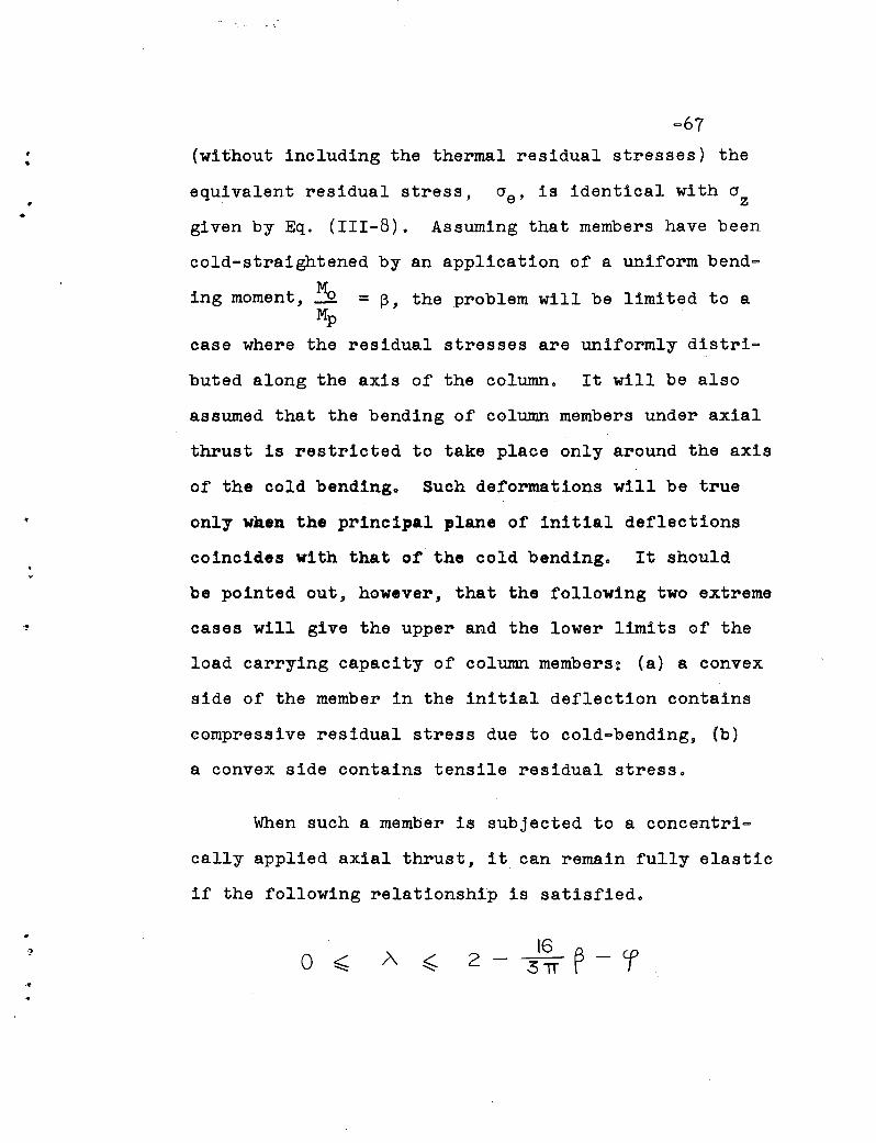
(without including the thermal residual stresses) the
equivalent residual stress, ae , is identical with azgiven by Eq. (III-8). Assuming that members have been
cold-straightened by an application of a uniform bend=
ing moment, Me =~, the problem will be limited to aMp
case where the residual stresses are uniformly distri=
buted along the axis of the column. It will be also
assumed that the bending of column members under axial
thrust is restricted to take place only around the axis
of the cold bending. Such deformations will be true
only when the principal plane of initial deflections
coincides with that of the cold bending. It should
be pointed out, however, that the following two extreme
cases will give the upper and the lower limits of the
load carrying capacity of column members: (a) a convex
side of the member in the initial deflection contains
compressive residual stress due to cold-bending, (b)
a convex side contains tensile residual stress.
When such a member is subjected to a concentri-
cally applied axial thrust, it can remain fully elastic
if the following relationship is satisfied.
•o ~
162 - 31T ~ - r

••
•
~68
If the column is compressed beyond this elastic limit 9
possible yield patterns will be as shown in Fig. v-5 9
the parameters, el , e2 , and 93
being determined from
Eqso (V~51) and (111-8) by taking f = 1.
Elastic-plastic case (A):
(V-21)
,. Elastic-plastic case (B):
8, is given by Eqo (V-21)
(V-22)
Elastic-plastic case ,(C):
J (V-23)
83 is given byEqo (V-23).
o..,.
-69
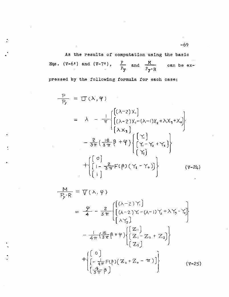
As the results of computation using the basic
Eqs ° (V-6 t ) and (V-7 t ), P M- and Py PyoR
can be ex-
pressed by the following formula for each case:
.-.•
MR'Ry
(v-25)
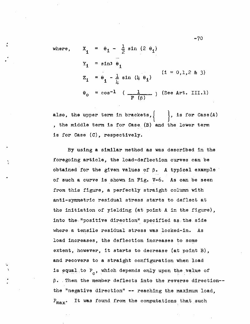
-70.• 1 sin (2 ei )where, Xi = 9i - 2
Yi = sin) 9i(i = 0,1,2 & 3)
Zi = 9i
1 sin (4 9i )4
eo = cos-l ( 1 ) (See Art. 111.1)F «(3)
also, the upper term in brB:Ckets,{ }, is for Case(A)
, the middle term is for Case (B) and the lower term
is for Case (C), respectively.
By using a similar method as was described in the
foregoing article., the load-deflection curves can be
obtained for the given values of 13. A typical example
of such a curve is shown in Fig. v-6. As can be seen
from this figure, a perfectly straight column with
anti-symmetric residual stress starts to defl~ct at
the initiation of yielding (at point A in the figure),
into the. "positive direction" specified as the side
whe;re a tensile residual stress was locked",:, in. As
..
load incr,eases, the deflection increases to some
extent, however, it starts to decrease (at point B),
and recovers to a straight configuration when load
is ~qual.,to P , which depends only upon tlle vtilue of" c
(3 •. Then the member deflects into the reverse direction--
the "negative direction" -- reaching the maximum load,
Pmax• It was found from the computations that such

-71
a distinctive phenomenon can happen only in the case
of shorter columns for which the value of P is highermaxthan Pc; on the other hand, relatively longer columns
deflect monotonously in the "positive direction" and
the maximum load will never exceed Pc. If column
members have small amounts of "negative initial deflec-
tions" - convex side of member contains compressive
residual stress - their load carrying capacity is relative-
ly high, and even higher than that of a perfectly straight
column in the case of longer members. In general, it
has been concluded from this analysis that the ultimate
strength of cold-bent column members with "positive
initial deflection" is distinctly' lower than that of
the members with "negative initial deflections". Figure
V-7 indicates these facts, when ~ = 0.883.
v.4 EXPERIMENTAL VERIFICATION OF THE THEORY
Concentrically loaded column tests were carried
out-to verify the theoretical predictions of ultimate
strength of high strength steel round columns which
have been developed in the preceding articles. (22) (24)
(See Photograph 2) According to the magnitude and the
distribution pattern of residual stresses present in
the members, the test specimens can be essentially

•,-72
divided into three groups as followsg
A) Polar symmetric pattern, low magnitude -- tempered
or stress-relieved material.
B) Polar symmetric patt~rn, high magnitude
quenched material.
c) Anti-symmetric pattern, high magnitude
bent material.
cold-
•,
•
The columns were tested in a flat-ended condition,
and the effective length, kL, was determined by directly
measuring the locations of zero curvature by means of
strain gages. It was therefore unnecessary to consider
the effects of unavoidable eccentricities in loadings
upon the column strength. Since the only necessary
and important factor is the initial deflection of the
members, precise measurements in two perpendicular
directions were made on each specimen.
First of all, in order to check the assumption
made in Art. V.labout the relationship between deflec-
tion and curvature at mid-height of columns, test
results of these values were compared with the assumed
formula, Eq. (V-I). Figure v-8 shows that this assump
tion is satisfactory.
... -73
The column behavior is best observed in Figures
V-2, V-3 and V-6, as an example for each group of
material, respectively. The tests can be compared
with the corresponding theoretical curves having the
same doR
values.
,,
.,
T~~le 1 summarizes the test results and theoreti
cal predictions on the ultimate strength of columns.
It can be seen from this comparison that fairly good
agreement between theory and experiment has been
obtained for this investigation.

."VI. SUMMARY AND
-74CON C L U S ION
•
•1
In this dissertation the following p~oblems -about
high strength steel round columns are investigated
theoretically and compared with experimental results.
I.) Thermal transient and residual stresses caused by
heat treatment.
2.) Cold-straightening of column members and the result
ing residual stress.
3.) The effect of these residual stresses on the in-
elastic buckling strength of round columns.
4.) The effect of residual stresses and initial deflec
tions on the ultimate strength of round columns.
The results of the stUdy presented in the pre
ceding chapters will be surmnarized in the following
items.
(1) Using a temp~rature-dependent stress-stra~n
relationship and Mises t yield criterion, the
thermal transient and residual stresses in a
heat-treated solid circula~ cylinder were
analyzed, and a method for obtaining an approxi
mate solution by step-by-step procedures was
presented. As an example, numerical calcula
tions were performed for the ease of a water-
•
'0
1
•
-75quenched steel bar. Residual stress measure-
ments on specimens which were subjected to such
a final heat treatment as quenching, air-cooling
or stress-relieving were carried out by using
the "combined-method" together with the ordinary
"boring-out metho4". It was observed that the
residual stresses present in the steels heat-
treated by either tempering, air-cooling or stress
relieving are less than about 15-20% of the yield
stress of the material, whereas the as-quenched
steels contain considerably higher compressive
residual stresses (axial and tangential) in the
outer part of the cross section. (Figs. 1I-4 and
1I-5) A satisfactory correlation between the
theoretical analysis and the test results has
been obtained on the magnitude and distribution
of the residual stresses in a water-quenched
steel.
(2) The relationship between the initial out
of-straightness of column members and the required
amount of bending moment to be applied by cold
straightening was obtained. With this informa
tion the residual stress caused by straightening
can be estimated by Eq. (III-8). The "modified
•,.
•
..,
boring-out method ll for the measurement of residual
stresses of non-polar symmetric pattern was
developed with the use of MacLaurin's expansion
formula for solving Voltera's integral equation
of the first kind. An application of this method
to the measurement of the cold-straightening
residual stress in round bars has given a fairly
good agreement with the theoretical results. (Fig.
III-3c) Furthermore, an approximate but simpler
method, the lIbeam dissection method ll was also used
for the measurement; a satisfactory approximation
as compared with the results from the exact method
was obtained.
(3) The irifluence of triaxial residual stresses
in column members upon their compressive strength
in the inelastic range was investigated by using
the lIequivalent residual stress ll concept which
assimilates the problem to the case of uniaxial
residual stress, thereby simplifying the analysis
to a great extent. With aknown pattern of the
equivalent residual stress and the static yield
stress of the material, the average stress-strain
relationship in a short column was obtained and
verified by the stub column test results. (Fig.
IV-2)
..
.\l
..
<.
•
-77
A lower and an upper bound for the in
elastic buckling load of round columns, the tan
gent modulus load, and the reduced modulus load,
were obtained in terms of the tangent modulus,
Et • It'WBS then shown that the actual tangent
modulus load is proportional to (Et/E) 2 9 whereas
the reduced modulus load is approximately pro
portional to the ratio (Et/E). (Eqs. (IV-IO)
and (IV-16).)
(4) The maximum load carrying capacity of axially
loaded round columns was analyzed by including
the effects of both the residual stresses and
initial deflections. Two distinct patterns :for
the residual stresses, namely polar symmetric
and anti-symmetric, were considered in order to
investigate the influences of residual stresses
due to heat treatment and cold-straightening on
the ultimate strength of columns. Members con
taining high thermal residual stresses caused by
water-quenching, for example, carry approximately
a lO-~O% lower load than air-cooled or stress
relieved steel columns, provided that their
generalized slenderness ratio, 7 , and initial
deflections, do' are the same. (Fig. V-4)
'f
•
-.•
The ultimate load of the cold-straightened
column (do = 0) is reduced to about 73% of Py '
when 7= 1.0, because of the presence of the un~
favorable residual stress.
In general, the reduction of the ultimate
strength due to initial deflection is quite pro
nounced, and this is especially true in the
region 1=1.00. In the exceptional case, how
ever, when a column is cold-straightened slightly
toward the opposite direction from the original
curvature, (do < 0), the maximum load carrying
capaci ty of columns for 7» 0.9 can exceed the
strength of a comparable perfectly straight
column. (Fig. V-7)
In order to verify the theoretical analysis
of the ultimate strength developed in Chapter V,
column tests have been carried out, and fairly
good agreement between the theoretical predic
tions and the test results was obtained. (Table 1)
(5) The method used in this dissertation may
be similarly extended to the solution for hollow
circular cylindrical columns if their wall
thickness is sUfficiently large so that a possi~
bility of local buckling is elminated. If the

-~
magnitude and the distribution of residual
stresses are similar to each other at the outer
part of the cross section, then the results
obtained for solid circular columns can be
approximately substituted for that of the hollow
cylindrical columns, because the penetration of
yielding usually does not develop deeply into
the inside of the cross section until the
ultimate load is reachedo
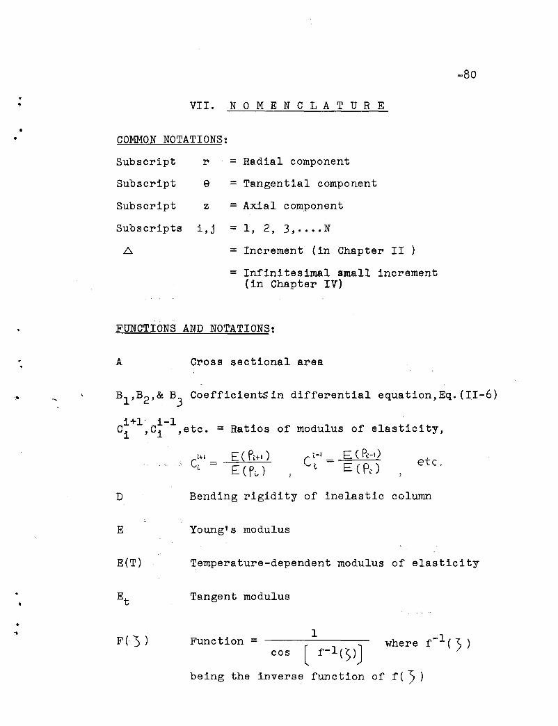
...-80
VII. NOM E N C L A T U R E
• COMMON NOTATIONS:
Subscript
Subscript
Subscript
r
z
= Radial component
= Tangential component
= Axial component
Subscripts i,j = 1, 2, 3, .... N
= Increment (in Chapter II )
= Infinitesimal small increment(in Chapter IV)
FUNCTIONS AND NOTATIONS:
A Cross sectional area
Bl ,B2 ,& B3
CoefficientS in differential equation,Eq.(II-6)
i+l i-IC
i,Ci ,etc. = Ratios of modulus of elasticity,
E ( PL+I )
E ( Pt- )C,-I = E ( P~-,)
\. E (P.) etc.
Bending rigidity of inelastic column
Temperature-dependent modulus of elasticity
Young's modulus
where f- l ( ") )1
cos
Tangent modulus
Function =
D
E
E(T)
Et
..::>
F( '5 )
being the inverse function of f ( '5 )

... First integral ofF() ), - J~ Fc))od')a
16
-81
I
13The Second integral of F(:> ), = C..:n:.. F, (s }d::s
16
Moment of inertia
Effective moment of inertia
Bessel function of order zero and one,respectively
Second invariant of deviatoric stress tensor,.seeEq. (II-14>
J 2 ('t l , A) Function, seeEq. (II-16)
'"!'.
L
M
MP
M
N
p
Kernel of integral equation, ·Eq. (III~ll)
Length of beam or column
Bending moment
Full plastic moment
Uniform bending moment ( = poQ )
Bending moment associated with a release of. residual stress
Number of division
Axial thrust
Pc
•Pcr
Pmax
Pr
Pt
Py
QG,Qz
R
~:
T
-82
Axial thrust at point C of load-deflectioncurve (see Fig. V-6)
Critical load as defined byEq. (IV-7)
Maximum load
Reduced modulus load: '.'j
Tangent modulus load
Full plastic load ( = cryA)
Incremental resultant force in tangential andaxial direction, respectively, due to correctionstress
Radius of cross section
Function obtained by strain measurement
Temperature
Initial temperature
Axial thrust function = p!py
Moment function = ·11PyR
Function = "i - ~. sin (2Si )

-83
Function = sin3 ei
Function = e i
a, b Constants in equivalent residual stress pattern
c Constant for cooling rate, seeEqo (II-I)
d Deflection of column at mid-length
Initial deflection of column at mid-length
e Proportional factor =(L,(Jr,e,z]r
A (jr, e, Z
Radius of elastic core
~fective column length factor
Late~al load for cold-bending
Coordinate (radial direction)
3 (IT _ eo + 41 sm 4 eo) + .5/17 3 eo8 cas eo 2 '
Constant in equivalent residual stress pattern
Interval of division = liN
Function =
Distance between loading point and end of beam
.,. 'Real root. of -Eqo (II-I')
f(eo ) .
I).
h
k
1-
rot
n
p
r..
r e
••
s
-84
Radius of gyration ( = ~ )
Distance between centroidal axis and neutralaxis
s
t
u (z)
u*
v (r)..
x
z
zo
a (T)
Parameter = siR
Time
Lateral deflection of beam or column
= tv1 p L2
(3- ~2.)24 EI
Radial displacement
Coordinate (in the direction of lateralload, p)
Coordinate (axial direction)
Boundary between elastic and elastic-plasticregion. of beam
Linear thermal expansion coefficient .
MacLaurin's coefficients~ see Appendix C
pa.rameter for "cold-straightening of column" ,
= Mo/~
Parameter = L/2
..e strain (compressive one is taken as positive)
Parameter =
.~.. eave
-85
Average strain
Symmet~ic part of strain released by boringout
strain released by boring-out
Anti-symmetric part of strain released byboring-out
p ·zMp
Non-dimensionalized coordinate =~
Non-dimensionalized coordinate = (X/R)2
"Generalized" slenderness ratio
Coordinate (tangential direction)
80
,'11 ,'12 ,83 & '1·u· Parameters for elastic-plastic
boundary in the cross section
Thermal diffusivity
..
Parameter, = '0'0'
0'Y
Parameter for elastic-plastic boundary inthe cross section
-86.... F
'. 15"
Pe
r0 , f1T
Non-dimensionalized coordinate = r/R
Non-dimensionalized coordinate =(r/a)2
Parameter for radius of elastic core =(re/R)
Parameters for elastic-plastic boundary inthe cross section
Correction stress
stress (compression is taken as positive)
Transient or residual stress in radialdirection
stress at the'center of cross section asdefined by.Eq•. (V-4)
,,- .".',1 :;, '-.'
Linear stress
Equivalent residual stress
Average stress
cr
crave
cre
crt,.
., cro
-cr
crr
Transient or residual stress in tangentialdirection
Trans1~nt or residual stress in axialdirection
..cry Yield stress i~ simple tension
A crtZ
Transient stress in axial direction whenboth ends are fixed (increment)
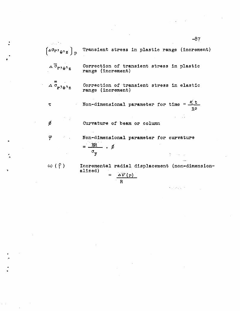
•-.-87
(.I::,,(Jr, Q' Z ) P Transient stress in plastic range (increment)
Correction of transient stress in plasticrange (increment)
=Correction of transient stress in elasticrange (increment)
Non-dimensional parameter for time = fC tR2
Curvature of beam or column
Non-dimensional parameter for curvature
= . ~
~V-(r) .
R
=
Incremental radial displacement (non-dimensionalized)
w ( P)
,,",,
'.
•,..
VII. TAB L "E, FIGURES AND
-88
...
P HOT 0 G RAE H S
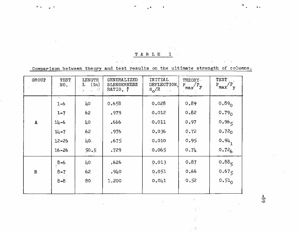
..
TAB LE 1
Comparison between theory and test results on the ultimate str~ngth of columns.
GROUP TEST LENGTH GENERALIZED INITIAL THEORY, TEST'NO. L ( in') SLENDERNESS DEFLECTION) P Ip P ./p'
, RATIO, 7 doiR .. ma1C y max Y- .-' ' ,
-.---_ ...
1-6 40 0.658 0.028 0 089' 0.890,,-
1~7 62 ' 0979 0.012 0.82 0 0790
A 14-6 40 .666 0.011 0.97 0 0965
14-7 62 0976 0 0036 0.72 0.720
12-'26 40- 0675 0 0010 0 095 0 0941
16-26 50.5 .729 0.065 0.74 0. 726
8-6 40 .626 0.013 0.87 0 0885"
B 8-7 62 0940 0 0051 0 066 00675
8-8 80 1 0200 0 0041 0 052 00510
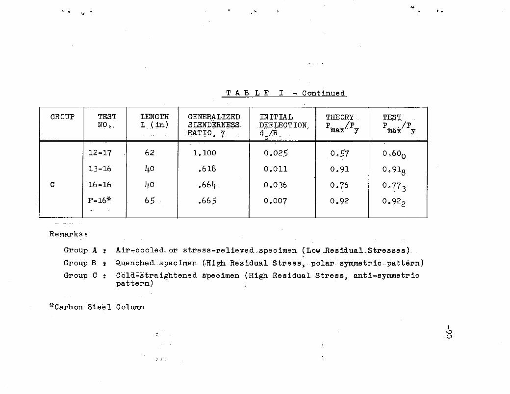
'"', ,;;
TAB LEI - Continued
GROUP TEST LENGTH GENERALIZED INITIAL THEORY ... TEST'NO~ . L_( in.) SU;N1):[mN~~S. .DEFLECTION; P. !p P .. ·... /p
RAT:J:O, ~1 d jR . max -. y max y- -, -. o .
12-17 62 1.100 0.025 0.57 0.600
13-16 40 .618 0.011 0.91 0.918
C 16-16 40 .. 664 0.036 0.76 0.77 3F-16* 65 .665 0 .. 007 0.92 0.922- !
Remarks:
.; it
Group A :
Group B :
Group C :
Air~cooled.or s.tress-reliev:ed.spec imen. (Low.ResiduaLS.tresse s)
Quenched... specimen (High Residual Stress,polar. ~ym.lJ1etr1.c.pa:ttern)
Cold~straightened specimen (High Residual Stress, anti-symmetricpattern)
*Carbon Steel Column
D...0o
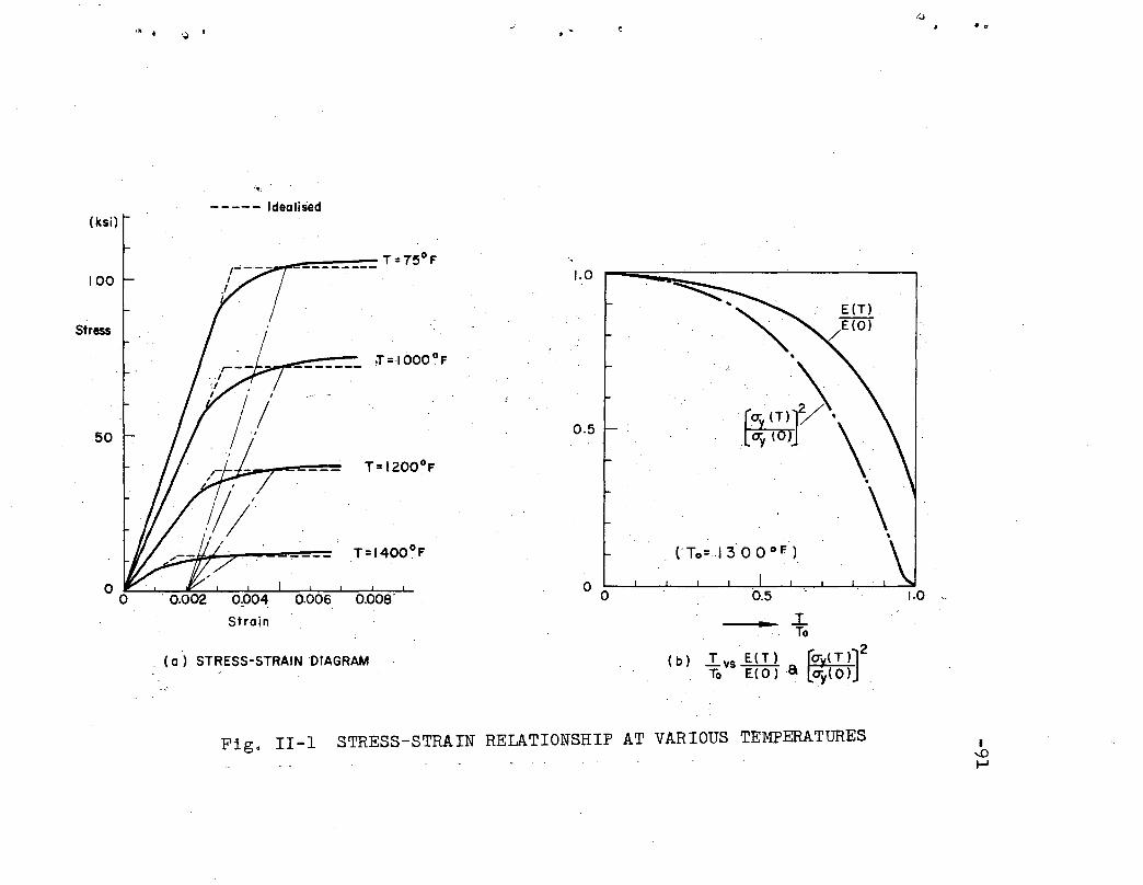
(ksi)----- Idealised
.0
________ T=750F
100
.Stress
50
o.ooa'Strain
. (a) STRESS-STRAIN DIAGRAM
1.0
0.5
. A
. (To=13000 F)
E(T) .
/E(O)
Fig. 11-1 STRESS-STRAIN RELATIONSHIP AT VARIOUS TEMPERATURES
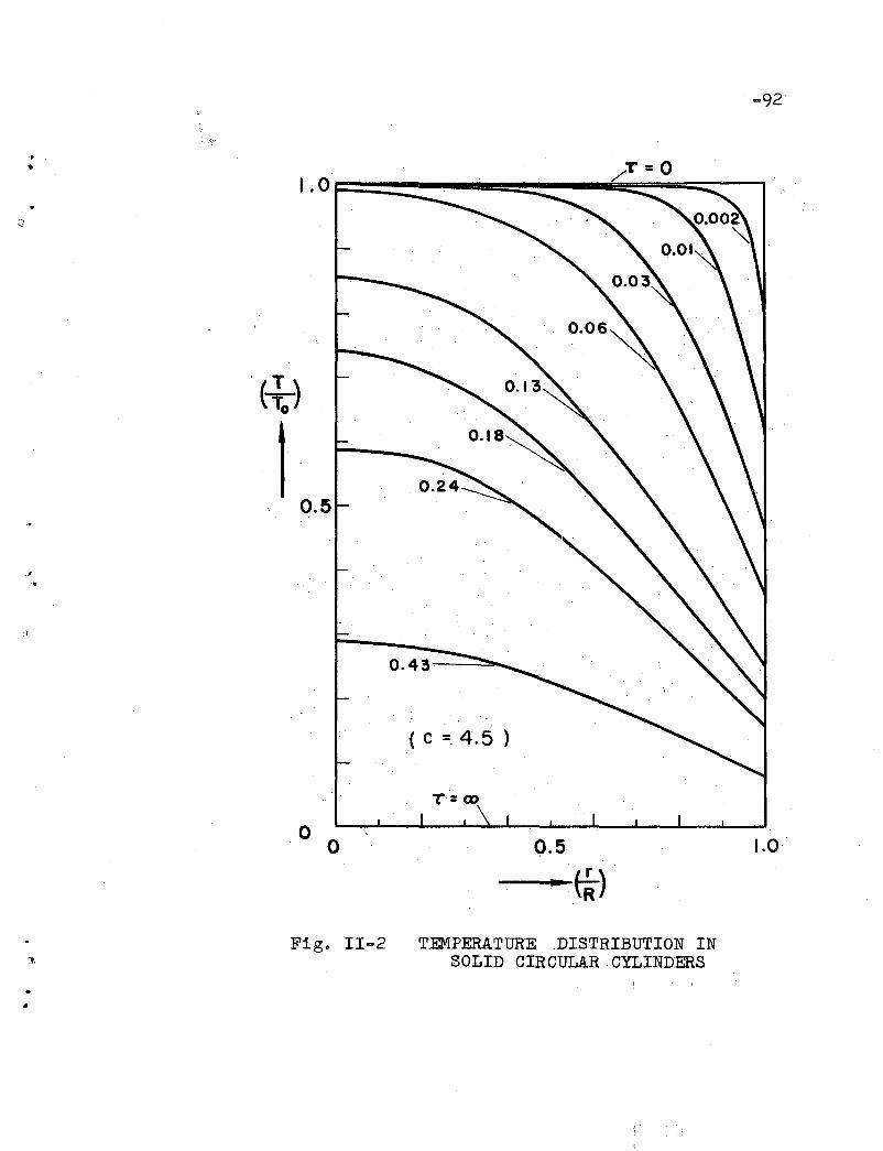
·. ...
i
, T(-,=;)
t0.5
o 0
T=oo
0.5
- ......_ffi-)
-92
1.0
.:?
•
Fig. II-2 TEMPERATURE DISTRIBUTION INSOLID CIRCULAR CYLINDERS
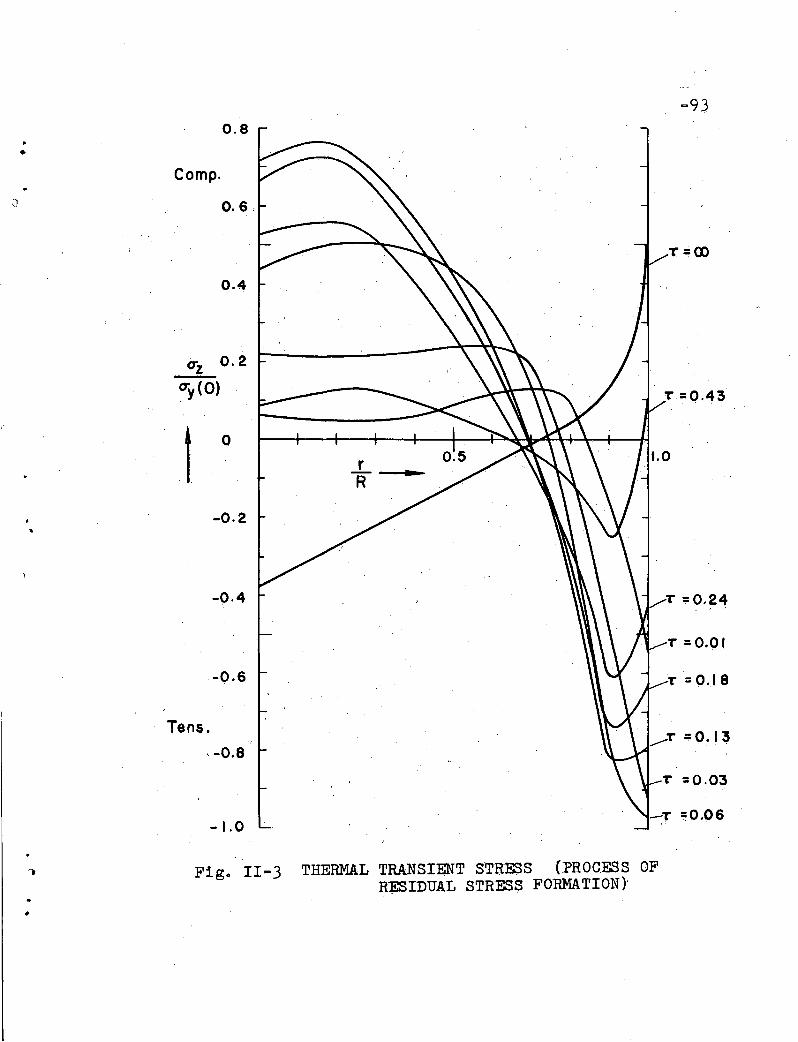
T =0.03
-T ~0.06
..........T=0.13
..L_.....R
o
-0.2
-0.4
-1.0
·-0.6
t
o-z 0.2
O"y (0)
Tens.,-0.8
-930.8
•Compo
J 0.6,
T =00
0.4
Figo II-3 THERMAL TRANSIENT STRESS (PROCESS OFR~IDUAL STRESS FORMATION}
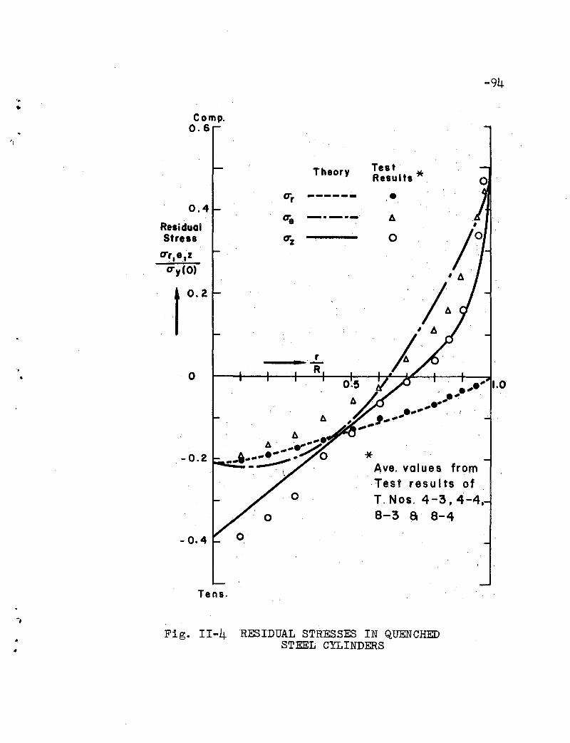
-94
•Compo
0.6
Theory TestResults *" o
*Ave. values fromTest results ofT. Nos. 4-3. 4,...4,8~3 a 8-4
o
0.4
-0.2r--....;;.
- 0.4
t 0.2
ResidualStress
CTr•• ,zCTy(O)
Tens.
-.,
.. Fig. II-4 'RESIDUAL STRESSES IN QUENCHEDSTEEL CYLINDERS
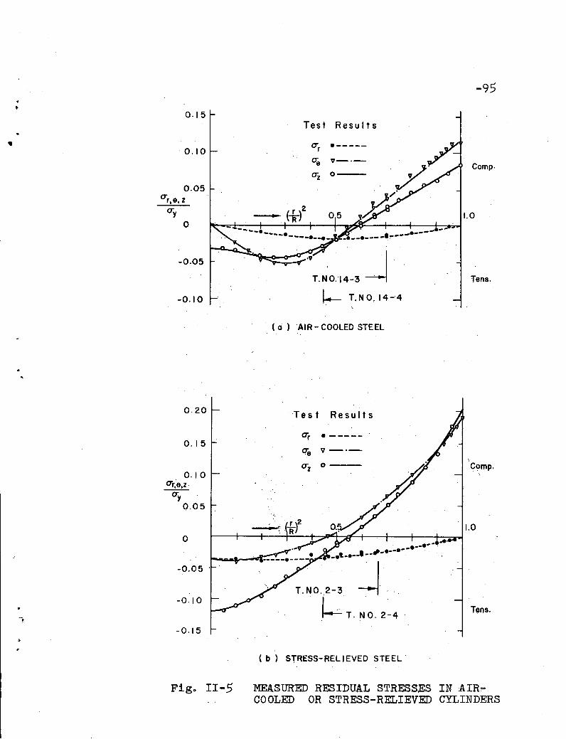
0.15
-95
Test Results
0.10
o
-0.05·
-0.10
0.20
0.15
0.10<Tr;e.z
<Ty0.05
o
-0.05
-0.10
-0.15
<Tr .-----
oe '1-'
<Tz 0--
·v JT.N'0.14'-3 .
~ T.NO.14-4
( a ) AIR - COOLED STEEL
Test Results
<Tr • -----
ere '1-'
<Tz 0 ---
...........• " ••••e·· . .••to •••• ••
T.NO ..2-3 --l~ T. NO. 2-4
( b) STRESS-RELIEVED STEEL'
Compo
1.0
Tens.
,.Compo
1.0
Tens.
Figo II-5 MEASURED RESIDUAL STRESSES INAIR~.
COOLED OR STRESS-RELIEVED CYLINDERS

-96
uL
x
( a ) .
~tress
"
( ~ )
•1.0 r-:-,.---------------------------,.-----,
0.5
Theoretical Curve'
(y= 0.2) ""
Elastic Limit----------------,--
o I· Test Results(T. No.IEHO)'
f. 0 0.2 0.4 0.6 0.8 1.0 1.2 1·4u(i Vuit
( c) MOMENT - DEFLECTION DIAGRAM
Fig o III-l COLD-STRAIGHTENING OF COLUMN MEMBERS

-97
••I.o~-------------...,;..------
1.0
.9791II
I
0.8 0.9Mo
'. M(=~)p
,
/., .
~~---1.0
0.7o
0.5
CTZ(cr.::y)
t
.,
Figo III-2RESIDUAL STRESS RESULTING INCOLD-STRAIGHTENED MEMBERS
..
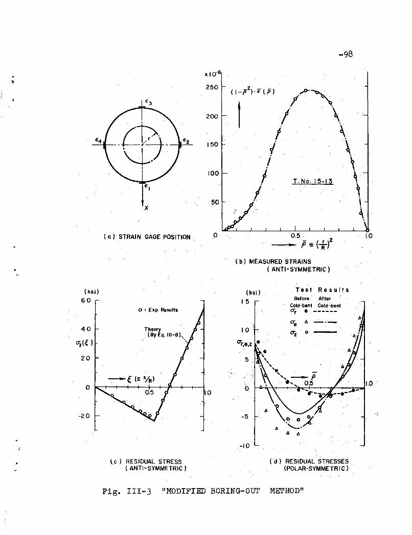
-98
x 10-6
x
250
200
150
100
50
,.'&.~
I "I' \.. ~
/ \/ ,I T·No.15-13 ~'I ,
. \
~
(a) STRAIN GAGE POSITION 0 0.5· 1.0
• .p:: (if( b) MEASURED STRAINS
• ( ANTI-SYMMETRIC).'
(ksi) (ksi) . Te 8 t RestAlts
60 - 15Before After
o : Exp. ResultsCold-bent Cold-bent
·O"r • ------Aae A _.-
40 TheoryO"z 0(By Eq. 111-8)
Oi({ )
20
~{(= X/R) .
b 1.000.5 1.0
-20 -5
-10
(c) RESIDUAL STRESS. ( ANTI-SYMMETRIC)
(d) RESIDUAL STRESSES(POLAR-SYMMETRIC) .
Fig. 111-3 "MODIFIED BORING-OUT MErHOD"

., • ••
--=:;;;;;~------~~ X= R
o Test· Results (l-NO.12-14)
'20 ·.40 60
~'_. Residual"Stress.~ (ksil
X=-R
4060
x
(0) SPECIMEN (b) RESIDUAL STRESS DISTRIBUTION
Fig. 111-4 "BEAM-DISSECTION METHOD"I
...0
...0

~\ " .. •
0.5
0.95· 1.0
Test Results
(T.Nos. 8-36 8-4)
-".-P(=t-)0.3
O~-4--t--+-+-+-+....-o:::":::--o-":;':~~=---1f----+--+----Io
0.3
O. I
0.2
0.4
-0.2
-0. I
.-0.3
Fig. IV-I EQUIVALEN'r RESIDUAL STRESSI
I--'oo
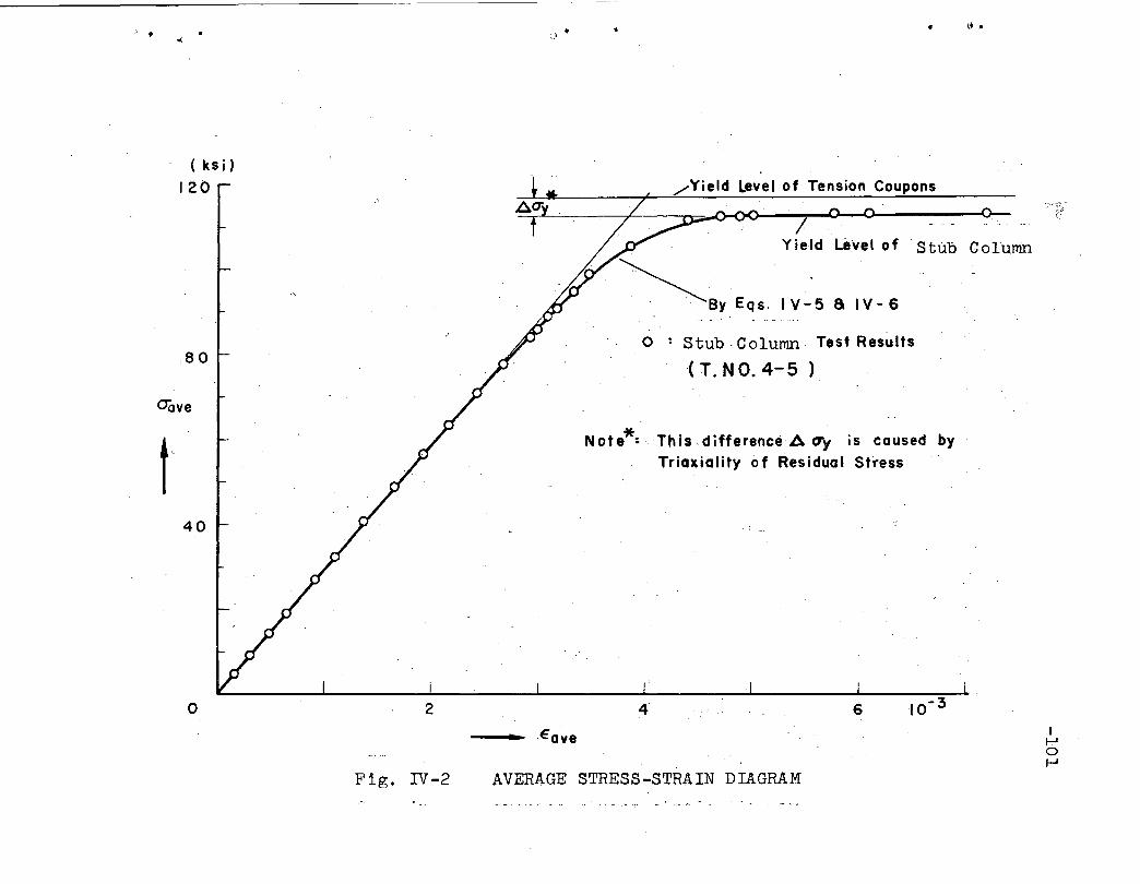
" . • i.t .•
~BY Eqs. IY-5 a IY-6
Note*:ThisdifferenceA CTy is caused byTriaxiality of Residual Stress
6
IYield Level of Stub Col'umn
Stub -Column' Test Results
,( T. NO. 4- 5 )
/Yield Level of Tension Coupons
o
42o
40
80
, (ks i)
120
OOve
-_.~ Eave If.,.JoI-'
Fig. IV-2 AVERAGE STRESS-STRAIN DIAGRAM
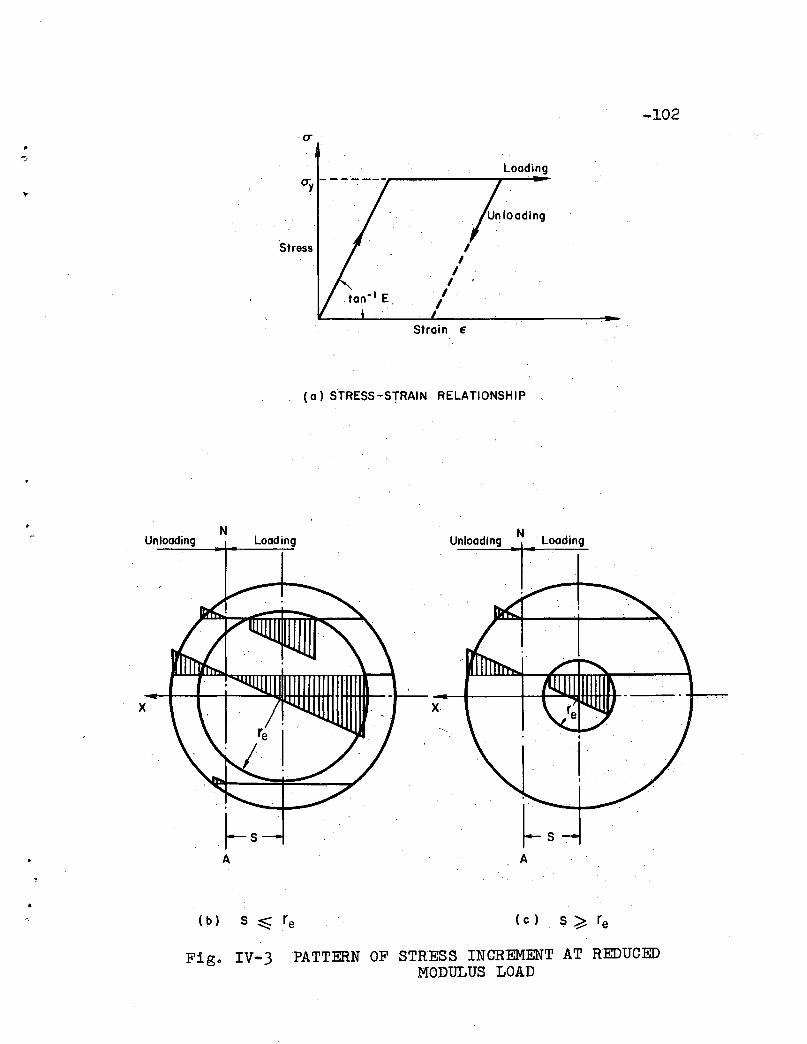
-102
Loading
II
II
II
Strain E
(a) STRESS-STRAIN RELATIONSHIP ,
~SA
Unloading
x
NLoading Unloading
N_1_ Loodlo,
A
(c) S ~ re
Fig. IV-3 PATTERN OF STRESS INCREMENT AT REDUCEDHODULUS LOAD
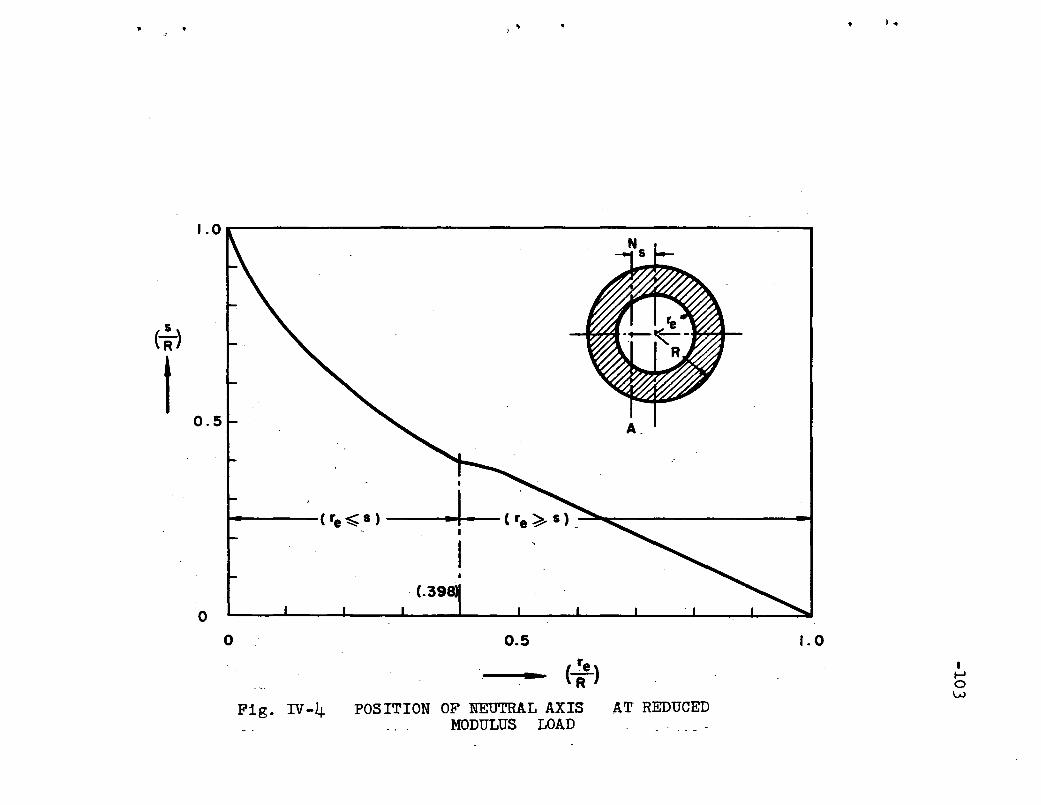
) , • ) .
1.0r-------------------------~---,
A .
•
......---( fe~ S ).----1-(f. ~ S) ~~------------- I
o
0.5
(:)
t
o 0.5
. (~e)
Fig. rv-4 POSITION OF NEuTRAL AXIS AT REDUCEDMODULUS LOAD
1.0
I.....o\.;.J
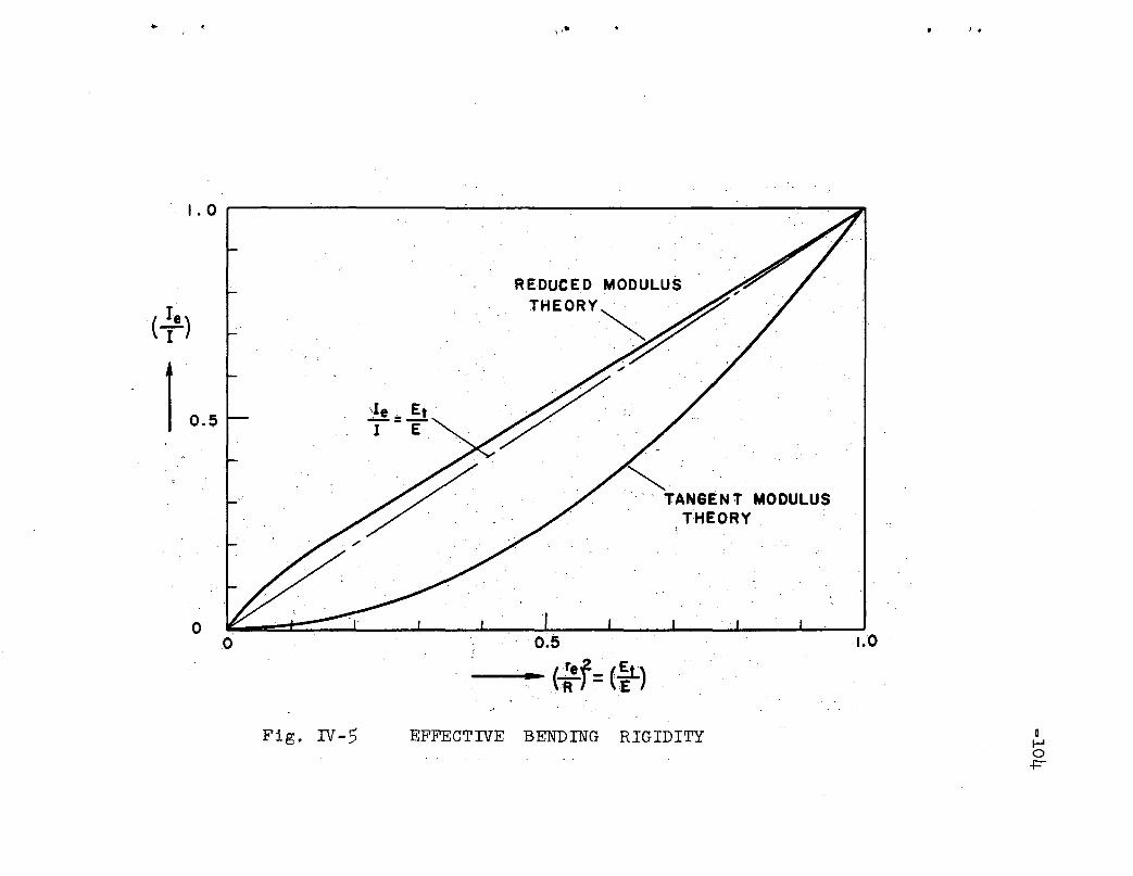
..'I \- ) .
1.0r----------~-----------------"""":""""~
,,1.0
~," , , TANGENT MODULUS
THEORY,
0.5
,__' .~, rrel-=(,!LE
')" }R>}. :
.0o
Fig. rv-5 EFFECTIVE BENDING RIGIDITY DHo
-t=""

-105
l,II'I'I
I'.
. L</>..
I ay I .
-U...' ' ,
.. ' ..
I. Actual Total'
Streu Distribution
=
EquivalentResidual Str.u
.. 08 +
LiriearStress .Correction Stress
.~
. (a) STRESS PATTERN .
Zone Zone. '.';;
CASE (A)
( b) ·..YIELD PATTERN
CASE (e.) .
Figo V-I YIELD PATTERN AND STRESS DISTRIBUTIONIN CROSS SECTION

-106
I. 0 ~-------'---------r-----------,
,,,
"l = 0.658 .'
0'; T. No 1-6
Elastlc- Plastic Region
Elastic· Region
o 0
I ,~
\." ~~---- ...:id[O~=~.~O~.O~'~I _' '/.
/0.028 .
0.5
.'o 0.06
Figo V-2 LOAD-DEFLECTION CURVES OF AXIALLY LOADEDCOLUMN (WITHOUT RESIDUAL STRESS)'
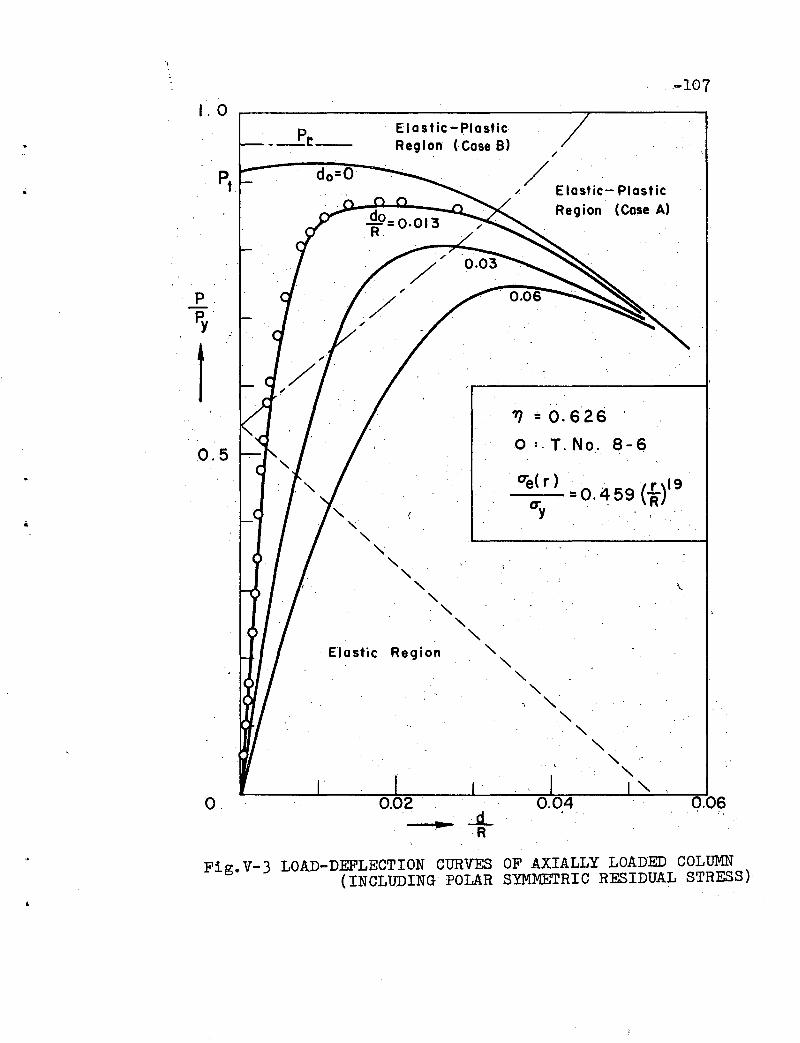
-107
0.060.04
// ,',
/ Elastic- PlasticRegion (Case A)
0:( ) "e r =0.459 (L)19try ,'. ~."
'TJ =0.626 '
o :. T. No. 8-6
Elastic-PlasticRegion (Case B)
0.02 '
Elastic Region
do=O
p__r__
o..;Jl.
R
FigoV-3 LOAD-DEFLECTION CURVES OF AXIALLY LOADED COLUMN(INCLUDING POLAR SYMMETRIC RESIDUAL STRESS)
1.0
0.5
p,P.'y
1
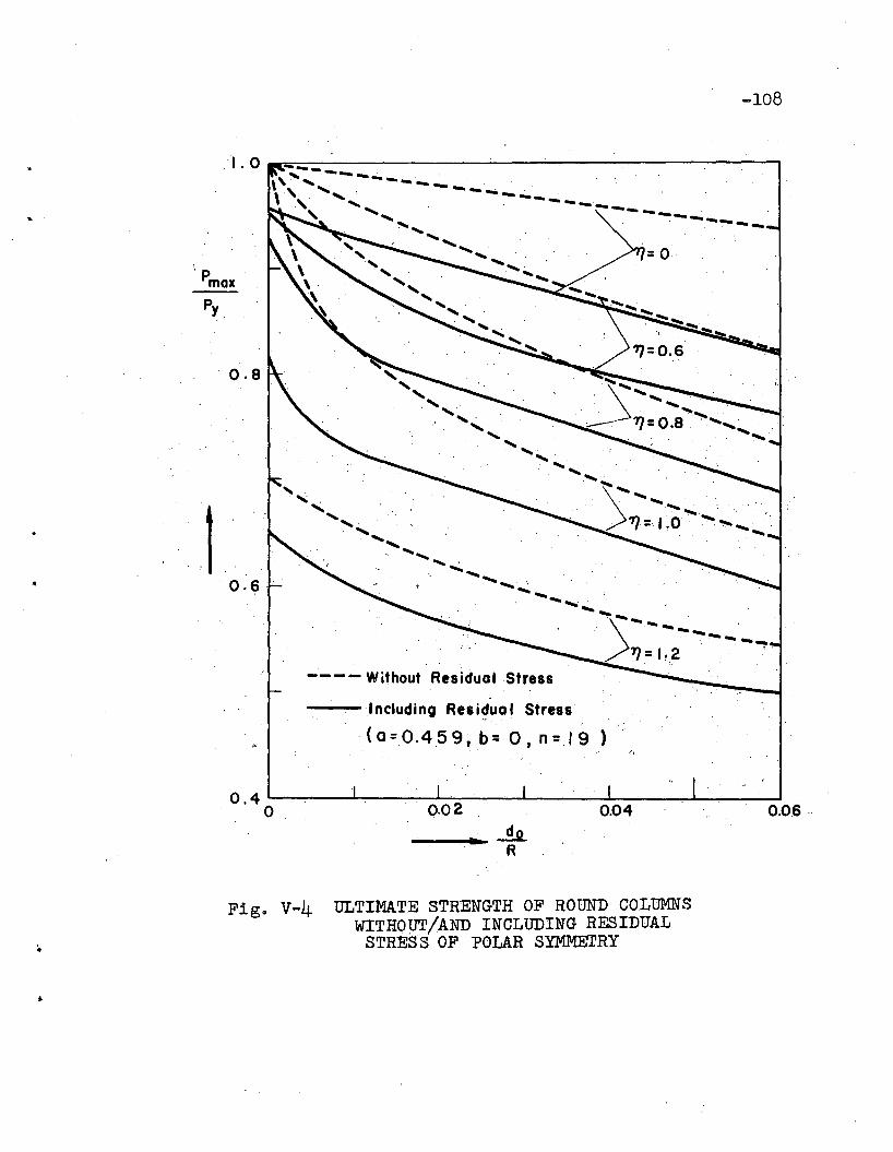
0.8
0.6
-108
---".. .'-~ ... -- ... - ------. -,...~--
" ...... ................... .....
' ......... .... .. ........ ' ...... ".... ..................
..... _)....._-- .,'.-.............7]= ",2 . '.' ~.
---- Without Residual Stress
1ncludi ng Rea idua 1 Stress., .(a=O.459,b=O, n=19)
......_ .........._ -i2.R
Figo V-4 ULTIMATE STRENGTH OF ROUND COLUMNSWITHOUT/AND INCLUDING RESIDUAL
STRESS OF POLAR SYMMETRY

,.
x
OJ.
·1 "I • .... ,.... ,'.... \ -1'......
v"" \ \ .\. -
x
\ 1-·\ .
\. . .
x
.~ Of
1'.... JI
/ ''''-J
CASE fA) CASE (8) CASE (C)
Fig. v-5 YIELD PATTERN AND STRESS DISTRIBUTION (COLD-STRAIGHTENED COLUMNS)
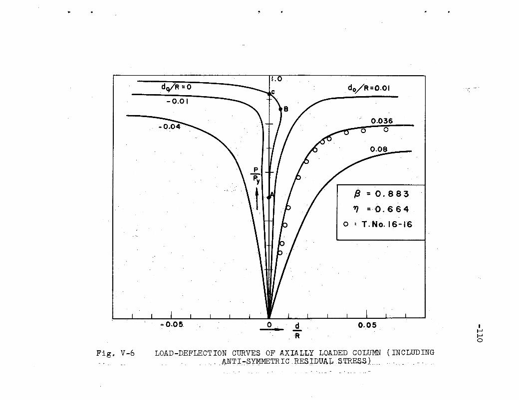
..
- 0.0 I
1.0 .. do/R =().Ol
0.036o 0
{3 =0.883
." =0.6 64
o : T.No. 16-16
-0.05 0.. dR
0.05 If-If-Io
Fig. V-6 LOAD-DEFLECTION CURVES OF AXIALLY LOADED COLUMN (INCLUDING.ANTT...~U!METR:r C .J:tES:rDUAL . $,TRE$S) ..
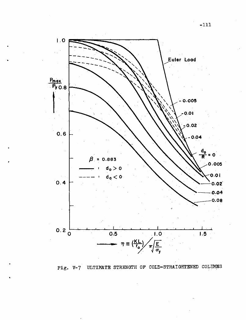
-Ill
..
1.0
PmaxpYO.S ro-_
t0.6
0.4
Euler Load../'
-0.005
-0.04
do .T=O
0.005
0.01
-0.02'
--'---,().04
~--0.08
Figo V-:-7 ULTIMATE STRENGTH OF COLD-STRAIGHTENED COLUMNS

-112
~ L ~ I··d={ ." ) '" .
5.0
176··
I 10
( KL)2 . 2.". ,(10)
46.5
1.0
T. No.
8- 8@
8- 6 0
8-7 6.
.d= 1764>__
Deflection
d (inch)
0.0 I
0.05
0.02
0.2 .
0.1
0.5
--...- Curvature ,4> ( 1/103 inch)
Fig. v-8 RELATIONSHIP BETWEEN DEFLECTION AND CURVATURE

Photo I. COLD-BENDING TEST
Photo 2. COLUMN TEST
-113
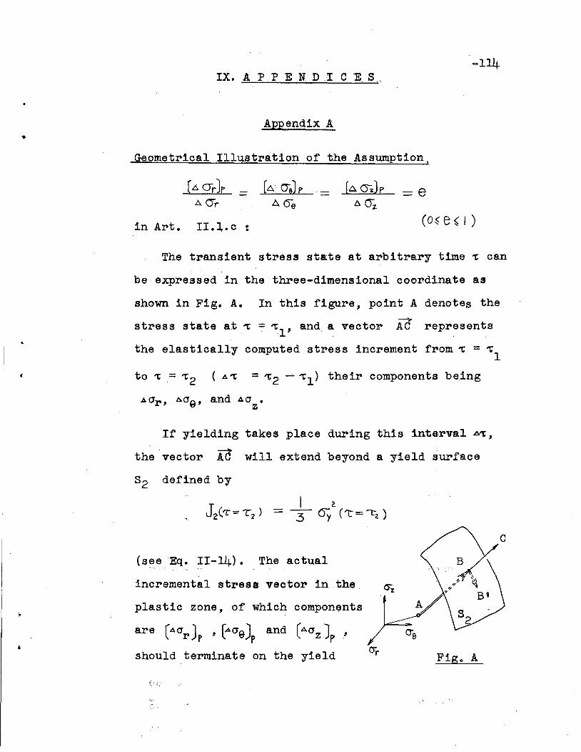
...114IX. AP PEN D .I CE 8!
Appendix A
Geometrical Illustration of the Assumptionj
=8
in Art. II.l.c: (O~e~l)
The transient stress state at arbitrary time ~ can
be expressed in the three-dimensional coordinate as
shown in Fig. A. In this figure, point A denotes the
(
--'>stress state at ~ = ~l' and a vector AC represents
the elastically computed stress increment from~ = ~l
to 't= 't2 (A~ = 't2 -- "1;1) their components being
If yielding takes place during thi.s interval ~'t,
the vector AC will extend beyond a yield surface
82 defined by
Fig. A
plastic zone, of which components
incrementalstresa vector in the
are r<\0r Jp , ~OeJp and (AOZJp ,
should terminate on the yield
(seeEq. II-14). The actual
f·

-115
surface 32
after intersecting the point B (which corres
ponds to the initiation of yield). In general, the
location of the ter.minal point Bt depends upon the
plastic flow occurred during yielding. For a material,
the stress-strain relationship of which is an idealized
one such as assumed in Art. II.I.b, there is. no increase
of.. stress in the case of a uniaxial stress state. Even'~ '.". . ". ' .
when the stress condition is triaxial, the qh~nge of
stress component dUring yielding (vector BEt) will,-. , .
be small as compared with the increment up to the
initiation of yielding (vector AB). Therefore,
.;r,. e'.- ... ~
= e •
wheI'e e ,is a proportional factor. This relationship
leads to the assumption
[A(Jzle-' "'eAOZ
If the time interval A 1: is sUfficiently small, then
this asSl mption will be satisfactory.
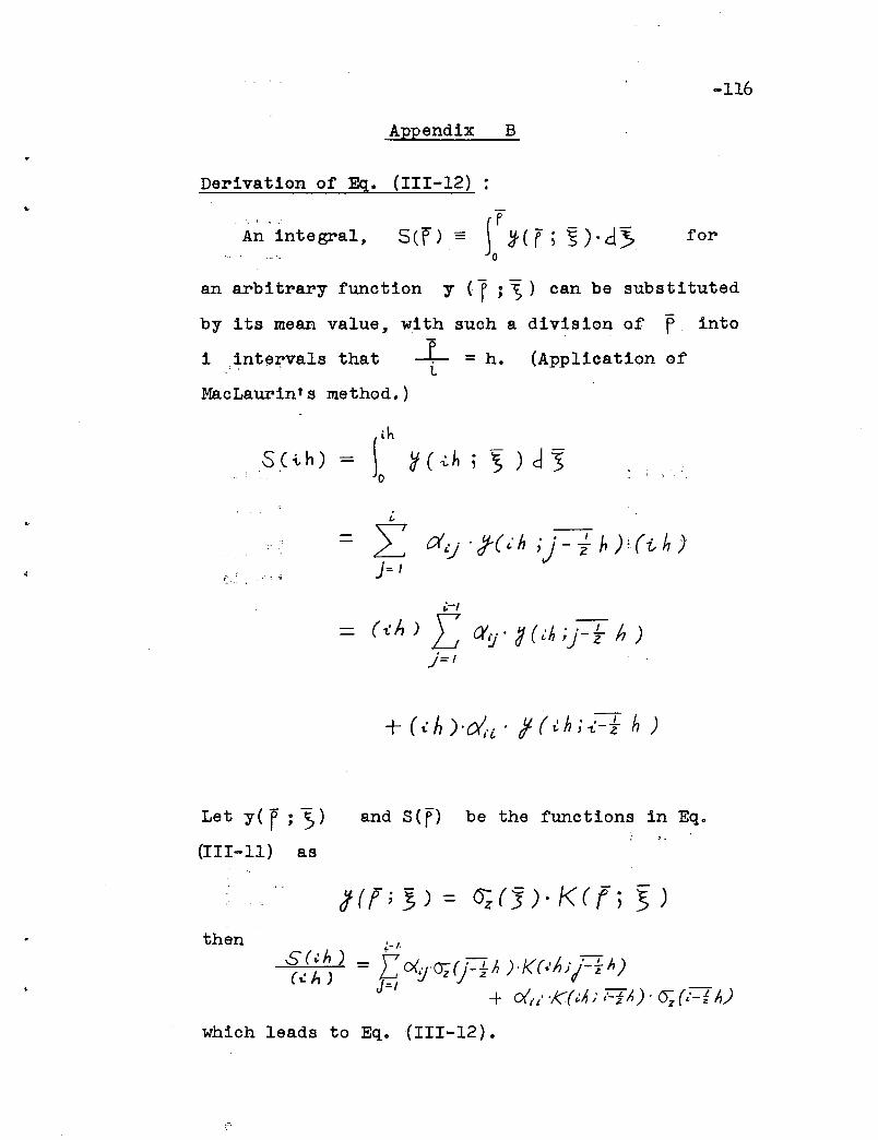
-116
Appendix B
Derivation of Eg. (III-12)
A;' integral, S(n '" (M- <r ; ~). d3> foro
an arbitrary function y (1 ; "'S) can be substituted
by its mean value, with such a division of f into
iintervals that ..LL
=h. (Application of
MacLaurin's method.)
th
S (i h) = ~ Y( -i.h !,) d 3o
/,
Z d'J' I( L' h ;) - ~ hr(t h))=1
i.-I
(tA) [ a'IJ' d{t.h;j-~ h)}=I
Let y( f ; ))(III-II) as
and S(f) be the functions in Eg.
then~-I\
S (~h) = \' o<.".~( "_L I ) ./((.'h . j_!... h)( L h ) . ~ y Vz ) z n ) fI Z
J-I -+ eX,/ 'KOA) l-i/') . cr; (,'-'1 h)
which leads to Eg. (III-12).
f: '

Appendix C
MacLaurin's coefficients, aij
:
-117
L
~ 1 2 3 4 5
1 1 - ... - ...
2 1/2 1/2 - ... ...
3 3/8 2/8 3/8 - ...
4 ·13/48 11/48 11/48 13/48 ..,.
5 275/1152 100/1152 402/1152 100/1152 275/1152,
/.
I-
-118x. R E FE R E N C E S
1. Bibber, L. C., Hodge, J. M. Altman, R. C. and DotY,WoD.A NEW HIGH;.,YIELD STRENGTH ALLOY STEEL FOR WELDEDSTRUCTURES; Trans. ASME, Vol. 74, No.3, pp. 269285 (1952).
2. Lambert, J.W.A METHOD OF DERIVING RESIDUAL STRESS EQUATIONS,Proceedings of the Society for "Experimental StressAnalysis, Vol. 12, No.1,' pp. 91-96 (1954).
, ',.-
3. Sac4s" :G.DER ,NACHWEIS INNERER Sl'ANNUNGEN IN STANGEN UNDRbHREN,~Zeitschrift fur Metallkunde, Vol. 19,pp. 352-357 (1927).
~:,., <. ~-
/ //4. Heteny;1, M.
HANDBOOK OF EXPERIMENTAL STRESS ANALYSIS: pp. -459578, John Wiley and Sons, Inc., New York, 1950.
5. BUhler, H. ,COMPLETE DETERMINATION OF THE STATE OF RESIDUALSTRESS IN SOLID AND HOLLOW METAL CYLINDERS,Residual Stresses in Metals and-Metal Construction,edited by W. R. Osgood, pp~ 305-329, Reinhold
,Publishing Corporation, New York, 1954.
6. Watanabe, M., Sato, K.~ and Goda, S.THERMAL AND RESIDUAL STRESSES OF CIRCULAR CYLINDERS
'- SUDDENLY COOLED FROM THE UNIFORMLY HEATED CONDITION,Journal of the Society of Naval Architects ofJapan, Vol. 88, p. 155 (1955).
7. Weiner, J. H. and HUddleston, J. V.TRANSIENT AND RESIDUAL STRESSES IN HEAT.-TREATEDCYLINDERS, Journals of Applied Mechanics, Vol.26, Series E, No.1, p. 31 (1959).
8. Bleich, F. , ,BUCKLING STRENGTH, OF METAL STRUCTURES, p.8,McGraw-Hill Book Co., Inc., New York, 1952.
.'
I.
-119
9. Shanley, F. Ro,INELASTIC COLUMN THEORY, Journal of AeronauticalSciences, Vol. 15, No.5 (May 1947).
10. Osgood, W.R.THE EFFECT OF RESIDUAL STRESSES ON COLUMN STRENGTH,Proc.' First National Congress of Applied Mechanics,p. 415 (June 1951).
11. Yang, C. H., Beedle, L. S. and Johnston,B,. G.RESIDUAL STRESS AN,D THE TIELD STRENGTH OF' STEELBEAMS, Welding Journal, Vol. 31, No.4, p. 205-s
'(April 1952).
12. HUbe~,A. W. and Beedle, L. S.RESIDUAL STRESS AND THE COMPRESSIVE' STRENGTH OFSTEEL, Welding Journal, Vol. 33, No. 12, p. 589-s(December 1954). •
"13. Thur1irriann, B.DER "EINFLUSS VONEIGENSPANNUNGEN AUF 'DAS KNICKENVON STAHLSTUTZEN, Schweizer Archiv f~r AngewandteWissenschaft und Technik, Heft 12, 23, (1957).
140 DUbe~g, J. E., and Wilder, T. W. IIIINELASTIC COLUMN BEHAVIOR, NACA Tech. Report,1072~ pp. 287-302,(1952).
15. FUjita, Y.BUILT-UP COLUMN STRENGTH, Fritz Laboratory ReportNO •. 249.2, Lehigh University, August, 1956
,(Ph.D. Dissertation).
16. Galambos, T.V~ and Ketter, R. LoCOLUMNS UNDER COMBINED BENDING AND THRUST,Journal of the Engineering Mechanics Division(Proceedings of'the American Society of CivilEngineers), Vol. 85, No.EM2, (April 1959).
17. Wilder, ToW. III, Brooks, W. A.,Jro and Mathauser,E.EoTHE EFFECT OF INITIAL CURVATURE ON THE STRENGTH OFAN INELASTIC COLUMN, NACA Tech. Note:2872, (January1953).
.'
.'
-120
180 Huber,Ao WoR:$SIDUAL STRESS AND THE COMPRESSIVE PROPERTIESOF STEEL, Fritz Laboratory Report No. 220A 022,Lehigh University, May, 1956 (PhoD. Dissertation)o
190 Carslaw, Ho S. and Jaeger, Jo C.CONDUCTION OF HEAT IN SOLIDS, po 176, OxfordUniversity Press, London, 1947.
20. TtmosAenko, S. and Goodier, J. No~HEORY OF'ELASTICITY, p. 408, 2nd ado, McGraw-HillBook Company, Inco, New York, 19510
21.USS"T-l" CONSTRUCTION ALLOY ST'EEL, United statesS~e~l Corporation Publication No. ADUCO 01060-59.
22. Nitta, ",Ao, Ketter, Ro L. and Thllrlimann, B.STRENGTH OF ROUND COLUMNS OF USS"T-l" STEEL,Fritz Laboratory Report No. '27201, LehighUniversity, (October, 1959).
23. Prager, W0 and Hodge, P. Go, Jr 0 p' 0 ',.44:'..i ,
THEORY OF PERFECTLY PLASTIC SOLIDS; JohnWiley & Sons, Inco, New York, 19510
, , "Nitta, A. and Thurlimann, Bo~CT OF COLD BENDING ON -COLUMN STRE.ijGTIi, FritzLaboratory Report No. 27202, Lehigh University,1960 (to be printed).
25. Hida~a" KoTHEORY OF INTEGRAL EQUATIONS, po 167, Kawade,Tokyo, 1941.
26. Tall, L. and Ketter, R. L.ON TH15 YIELD PROPERTIES OF STRUCTURAL STEEL SHAPES,Fritz Laboratory Report No. '220A.33, LehighUniversity, (November 1958) •

'"
- 121
XI. A C K NOW LED G MEN T S
This report has been prepared as a Ph.D. disserta
tion presented to the Graduate Faoulty of Lehigh
University. The author is greatly indebted to Dr.
Bruno Thurlimann who supervised the researoh projeot.
His enoouragement, advice and suggestions during the
development and preparation of' this report are sinoerely
appreciated. The author also wishes to express his
gratitude to Dr. Robert L. Ketter and to Dr. Theodore V.
Galambos f'or oontributing fruitf'ul discussions and
suggestions.
The project is sponsored by the United States
Steel Corporation. Sincere'appreoiation is expressed
in particular to Mr. John A. Gilligan f'or his valuable
disoussion during the progress of this investigation.
The work is being oarried out at the Fritz Engineering
Laboratory~' Lehigh University, of' whioh Prof'essor
William J. Eney is Director. The chairman of' the
Structural Metals Division is Dr. LYnn S. Beedle.
All test specimens were prepared and all tests
were perf'ormed at Fritz Engineering Laboratory. Sincere
appreciation is expressed to Mr. Kenneth R. Harpel,
Foreman of' the Laboratory. Heart-f'elt gratitude is
'.
•
- 122
extended also to the author's associates at, the
lab oratory for the ir wholehearted cooperation in the
testing and in carrying out the numerical computations.
The manuscript was typed by Miss Grace Mann.
Mr o Dian Po Jen assisted in the testing, in performing
the numerical computations and in drawing the figures o
Their cooperation is gratefully acknowledged •
Related Documents