HOSTED BY Ultimate bearing capacity analysis of strip footings on reinforced soil foundation Qiming Chen n , Murad Abu-Farsakh Louisiana Transportation Research Center, Louisiana State University, 4101 Gourrier Avenue, Baton Rouge, LA 70808, USA Received 25 September 2013; received in revised form 21 August 2014; accepted 20 October 2014 Available online 2 January 2015 Abstract Reinforced soil foundations (RSFs) have been employed in engineering practice to increase the soil bearing capacity and to reduce the potential footing settlement. The aim of this study is to develop analytical solutions for estimating the ultimate bearing capacity of strip footings on RSFs. A general failure mode for RSFs was first proposed based on previous studies conducted by the authors and test results from literature study. A limit equilibrium stability analysis of RSFs was performed based on the proposed failure mechanism. New bearing capacity formulas, which consider both the confinement and the membrane effects of reinforcements on the increase in ultimate bearing capacity, were then developed for strip footings on RSFs. Several special cases of RSFs were presented and discussed. The proposed model was verified by the experimental data reported in the published literature. The predicted ultimate bearing capacity was in good agreement with the results of model tests reported in the literature. The study showed that the depth of the punching shear failure zone (D P ) depends on the relative strength of the reinforced soil layer and the underlying unreinforced soil layer, and is directly related to the reinforced ratio (R r ). & 2015 The Japanese Geotechnical Society. Production and hosting by Elsevier B.V. All rights reserved. Keywords: Reinforced soil foundation; Ultimate bearing capacity; Failure mechanism; Limit equilibrium; Reinforced ratio 1. Introduction The use of reinforced soils to support shallow foundations has recently received considerable attention. The benefits of including reinforcements in the soil mass to increase the bearing capacity and to reduce the settlement of the soil foundation have been widely recognized. However, the devel- opment of a rational design method and a theory for reinforced soil foundations (RSFs) is lagging in comparison to RSF applications. These restrictions, on the other hand, inhibit the further development of reinforcement technology. Therefore, it is essential to investigate the proper failure mechanisms for reinforced soil applications. During the past forty years, many experimental, numerical, and analytical studies have been performed to investigate the behavior of reinforced soil foun- dations (RSFs) for different soil types (e.g., Abu-Farsakh et al., 2008, 2013; Adams and Collin, 1997; Binquet and Lee, 1975a, 1975b; Chakraborty and Kumar, 2014; Chen et al., 2007, 2009; Demir et al., 2013; Huang and Tatsuoka, 1990; Kurian et al., 1997; Sharma et al., 2009). The first experimental study reported in literature was conducted by Binquet and Lee (1975a) to evaluate the bearing capacity of sand reinforced by aluminum foil strips. Since then, several experimental studies have been conducted to evaluate the bearing capacity of footings on reinforced sandy soil (e.g., Abu-Farsakh et al., 2013; Adams and Collin, 1997; Akinmusuru and Akinbolade, 1981; Fragaszy and Lawton, 1984; Gabr et al., The Japanese Geotechnical Society www.sciencedirect.com journal homepage: www.elsevier.com/locate/sandf Soils and Foundations http://dx.doi.org/10.1016/j.sandf.2014.12.006 0038-0806/& 2015 The Japanese Geotechnical Society. Production and hosting by Elsevier B.V. All rights reserved. n Corresponding author. E-mail addresses: [email protected] (Q. Chen), [email protected] (M. Abu-Farsakh). Peer review under responsibility of The Japanese Geotechnical Society. Soils and Foundations 2015;55(1):74–85

Welcome message from author
This document is posted to help you gain knowledge. Please leave a comment to let me know what you think about it! Share it to your friends and learn new things together.
Transcript

H O S T E D B Y The Japanese Geotechnical Society
Soils and Foundations
Soils and Foundations 2015;55(1):74–85
http://d0038-0
nCorE-m
cefars@Peer
x.doi.org/1806/& 201
respondinail addrelsu.edu (Mreview un
.sciencedirect.com: www.elsevier.com/locate/sandf
wwwjournal homepage
Ultimate bearing capacity analysis of strip footings on reinforcedsoil foundation
Qiming Chenn, Murad Abu-Farsakh
Louisiana Transportation Research Center, Louisiana State University, 4101 Gourrier Avenue, Baton Rouge, LA 70808, USA
Received 25 September 2013; received in revised form 21 August 2014; accepted 20 October 2014Available online 2 January 2015
Abstract
Reinforced soil foundations (RSFs) have been employed in engineering practice to increase the soil bearing capacity and to reduce the potentialfooting settlement. The aim of this study is to develop analytical solutions for estimating the ultimate bearing capacity of strip footings on RSFs.A general failure mode for RSFs was first proposed based on previous studies conducted by the authors and test results from literature study.A limit equilibrium stability analysis of RSFs was performed based on the proposed failure mechanism. New bearing capacity formulas, whichconsider both the confinement and the membrane effects of reinforcements on the increase in ultimate bearing capacity, were then developed forstrip footings on RSFs. Several special cases of RSFs were presented and discussed. The proposed model was verified by the experimental datareported in the published literature. The predicted ultimate bearing capacity was in good agreement with the results of model tests reported in theliterature. The study showed that the depth of the punching shear failure zone (DP) depends on the relative strength of the reinforced soil layerand the underlying unreinforced soil layer, and is directly related to the reinforced ratio (Rr).& 2015 The Japanese Geotechnical Society. Production and hosting by Elsevier B.V. All rights reserved.
Keywords: Reinforced soil foundation; Ultimate bearing capacity; Failure mechanism; Limit equilibrium; Reinforced ratio
1. Introduction
The use of reinforced soils to support shallow foundationshas recently received considerable attention. The benefits ofincluding reinforcements in the soil mass to increase thebearing capacity and to reduce the settlement of the soilfoundation have been widely recognized. However, the devel-opment of a rational design method and a theory for reinforcedsoil foundations (RSFs) is lagging in comparison to RSFapplications. These restrictions, on the other hand, inhibit thefurther development of reinforcement technology. Therefore, it
0.1016/j.sandf.2014.12.0065 The Japanese Geotechnical Society. Production and hosting by
g author.sses: [email protected] (Q. Chen),. Abu-Farsakh).
der responsibility of The Japanese Geotechnical Society.
is essential to investigate the proper failure mechanisms forreinforced soil applications. During the past forty years, manyexperimental, numerical, and analytical studies have beenperformed to investigate the behavior of reinforced soil foun-dations (RSFs) for different soil types (e.g., Abu-Farsakh et al.,2008, 2013; Adams and Collin, 1997; Binquet and Lee, 1975a,1975b; Chakraborty and Kumar, 2014; Chen et al., 2007,2009; Demir et al., 2013; Huang and Tatsuoka, 1990; Kurianet al., 1997; Sharma et al., 2009).The first experimental study reported in literature was conducted
by Binquet and Lee (1975a) to evaluate the bearing capacity ofsand reinforced by aluminum foil strips. Since then, severalexperimental studies have been conducted to evaluate the bearingcapacity of footings on reinforced sandy soil (e.g., Abu-Farsakhet al., 2013; Adams and Collin, 1997; Akinmusuru andAkinbolade, 1981; Fragaszy and Lawton, 1984; Gabr et al.,
Elsevier B.V. All rights reserved.
List of symbols
B width of footingu top layer spacing, i.e., spacing between top layer
of reinforcement and bottom of footingh vertical spacing between reinforcement layersl length of reinforcementd total depth of reinforcement¼uþ (N�1)h.N number of reinforcement layersNp number of reinforcement layers located in punch-
ing shear failure zoneNT number of reinforcement layers located above
point cT tensile force in reinforcementDP depth of punching shear failure zonequ(R) ultimate bearing capacity of reinforced soil
foundationqu(R)1 ultimate bearing capacity of punching shear
failure zonequ(R)2 ultimate bearing capacity of underlying general
shear failure zonePp1 total passive earth pressure on vertical punching
failure surfaces aa0 and bb0
δ mobilized friction angle along vertical punchingfailure surfaces aa0 and bb0
Ca adhesive force acting on vertical punching failuresurfaces aa0 and bb0,¼caDP
ca unit adhesion of soil along vertical punchingfailure surfaces aa0 and bb0,
T1 tensile force acting on vertical punching failuresurfaces aa0 and bb0
α angle of tensile force T1 to horizontalT1x horizontal component of tensile force T1T1y vertical component of tensile force T1γ unit weight of soilDf embedment depth of footingKpH horizontal component of passive earth pressure
coefficientKs punching shear coefficientϕ friction angle of soil
Pp2 passive force acting on faces ac and bcC cohesive force C acting on faces ac and bcT2L, T2 tensile force acting on faces ac and bcPpc passive force due to cohesion c,Ppq passive force due to surcharge qPpγ, passive force due to weight of soil γc cohesion of soilq surcharge loadPpT passive force due to tensile force of reinforcement
T2Lξ angle of tensile force T2L to horizontalT2Lx, T2xhorizontal component of tensile force T2LT2Ly vertical component of tensile force T2LT2R tensile force acting on face gdη angle of tensile force T2R to horizontalT2RX horizontal component of tensile force T2RT2Ry vertical component of tensile force T2RF resisting force along log spiral cdr length of radial line of log spiral cd,¼r0e
θtanϕ
r0 length of bcθ angle between line bc and radial line of log spiral
curve cdXTR distance from center of footing to point where
tensile force T2R is appliedqu(UR) ultimate bearing capacity of unreinforced soil in
general shear failure zoneNc, Nq, and Nγ bearing capacity factorsβ angle between σ1 direction and bedding planeϕdesign design friction angle of soilϕpeak peak friction angle of soilϕcv residual design friction angle of soilχ percent of contribution of failure surfaces con-
trolled by soil’s peak friction angleRr reinforced ratioER elastic modulus of reinforcement¼J/tRJ tensile modulus of reinforcementAR area of reinforcement per unit width¼NtR� 1tR thickness of reinforcementEs modulus of elasticity of soilAs area of reinforced soil per unit width¼d� 1
Q. Chen, M. Abu-Farsakh / Soils and Foundations 55 (2015) 74–85 75
1998; Guido et al., 1986; Huang and Tatsuoka, 1990; Latha andSomwanshi, 2009; Lavasan and Ghazavi, 2012; Omar et al. 1993a,1993b; Yetimoglu et al. 1994), clayey soil (e.g., Abu-Farsakhet al., 2008; Chen et al., 2007; Chen and Abu-Farsakh, 2011; Daset al., 1994; Ingold and Miller, 1982; Mandal and Sah, 1992;Ramaswamy and Purushothaman (1992); Sakti and Das, 1987;Shin et al., 1993), aggregate (e.g., Chen et al., 2009; DeMerchantet al., 2002; James and Raymond, 2002), and pond ash (e.g., Beraet al., 2005; Ghosh et al., 2005). The aim of many of these researchefforts was to investigate the parameters and variables that wouldcontribute to the value of the bearing capacity ratio (BCR), whichis defined as the ratio of the bearing capacity of the RSF to that ofthe unreinforced soil foundation. The results of the experimentalstudies showed that the bearing capacity of soil was improved
when it was reinforced by reinforcements and that the amount ofimprovement was highly dependent on the layout of the reinforce-ments. Better improvements were obtained when the reinforce-ments were placed within a certain depth (or influence depth)beyond which no additional significant improvement occurred. Inother words, the BCR value would approach a constant/limitingvalue with an increasing number of reinforcement layers.From the experimental studies reported in the literature, two
fundamental reinforcement mechanisms can be distinguishedas contributing to the increase in bearing capacity of reinforcedsoil foundations (RSFs).
(1)
Confinement effect or lateral restraint effect: With theapplied load, the lateral forces are induced and the soil
Q. Chen, M. Abu-Farsakh / Soils and Foundations 55 (2015) 74–8576
particles are spread. Due to the relative displacementbetween the soil and the reinforcements, frictional interac-tion is induced at the soil-reinforcement interface. Forgeogrid reinforcements, the interlocking can be developedby the interaction of the soil and the geogrid. Conse-quently, lateral deformation or potential tensile strain of thereinforced soil is restrained. As a result, the verticaldeformation of the soil is reduced. Since soils are stress-dependent, improved lateral confinement increases thecompressive strength of the soil, and thus, improves thebearing capacity of the reinforced soil.
(2)
Membrane effect: With the applied load, the soil beneaththe footing moves downward; the reinforcement is thendeformed and tensioned. The deformed reinforcementdevelops an upward force that supports part of the appliedload. A certain amount of settlement is generally requiredto significantly mobilize the tensioned membrane effect,and the reinforcement should have enough length andtensile strength to prevent it from failing by pull out andrupture.Several researchers have presented analytical models for esti-mating the ultimate bearing capacity of RSFs based on either theconfinement effect (e.g., Huang and Tatsuoka, 1990; Michalowski,2004) or the membrane effect (e.g., Binquet and Lee, 1975b;Kumar and Saran, 2003; Wayne et al., 1998). With these twofundamental reinforcing mechanisms, the “deep footing” effect canbe formed under certain conditions. Here, the “deep footing” effectmeans that the performance of footings on a reinforced soilfoundation is very similar to that of footings on an unreinforcedsoil foundation with an additional embedment depth equal to thedepth of the reinforced zone. This effect was first proposed bySchlosser et al., (1983). Huang and Menq (1997) employed thiseffect to derive the ultimate bearing capacity formulas forreinforced sand. This effect is also considered in Wayne et al.’(1998) solution. With an increase in the number of reinforcementlayers, the “deep footing” effect leads to an almost linear increasein the bearing capacity ratio (BCR), and convergence cannot beobtained (i.e., the BCR value does not approach a constant/limitingvalue with an increasing number of reinforcement layers). Thisposes a big problem, especially in granular soil with a high frictionangle. The authors made great efforts to develop analyticalsolutions to overcome this problem (Chen et al., 2009; Sharmaet al., 2009). However, the developed analytical solutions wereonly applied to square footings and took different forms fordifferent soil types. Also, only a single reinforcement mechanism(either confinement effect or membrane effect) was considered inthose analytical solutions.
Therefore, this study will focus on strip footings on RSFs byconsidering the two reinforcement mechanisms (i.e., confine-ment effect and membrane effect) together. A general failuremechanism of RSFs is firstly proposed. The limit equilibriumstability analysis for RSFs, based on the proposed failuremechanism, is then performed as an attempt to develop arational unified analytical model for evaluating the ultimatebearing capacity of strip footings on RSFs. Finally, the
developed analytical solution is verified through the resultsof model tests reported in the literature.
2. Failure modes of reinforced soil foundations
As mentioned earlier, reinforcements can restrain the lateraldeformation or the potential tensile strain of the soil (confine-ment effect). In addition, deformed reinforcements can developan upward force (membrane effect). These effects will result inan increase in the bearing capacity of the RSF.Three potential failure modes of RSFs are shown in Fig. 1.
The first two failure modes, failure above the top layer of thereinforcement (Binquet and Lee, 1975b) (Fig. 1a) and failurebetween the reinforcement layers (Wayne et al., 1998)(Fig. 1b), can be avoided by keeping the top layer spacing(u) and the vertical spacing between the reinforcement layers(h) within an acceptable/reasonable range.Based on previous studies by Chen (2007), Chen et al. (2009),
Sharma et al. (2009), the third failure mechanism, i.e., a generalfailure mechanism of RSFs, is identified as a punching shear failurefollowed by a general shear failure (Fig. 1c). The value ofpunching shear failure depth Dp depends on the relative strengthbetween the reinforced zone and the underlying unreinforced zone.It can be zero (i.e., Dp¼0) if the strength of the reinforced zone isslightly larger than that of the underlying unreinforced zone, or ifthe reinforcement depth ratio (d/B) is relatively large. It also canpunch all the way through the reinforced zone (i.e., Dp¼d) if thestrength of the reinforced zone is much larger than that of theunderlying unreinforced zone and the reinforcement depth ratio (d/B) is relatively small.
3. Limit equilibrium analysis of reinforced soil foundations
First, we will consider the strip footing case with two layers ofreinforcement. One layer is located in the punching shear failurezone at a depth of u, and the other layer is located in the generalshear failure zone at a depth of uþh. The failure surface in the soilfor the strip footing at the ultimate load is shown in Fig. 1c. Theultimate bearing capacity of the RSF includes the contribution ofpunching shear failure zone a0abb0, qu(R)1, and an underlyinggeneral shear failure zone, qu(R)2, i.e., qu(R)¼qu(R)1þqu(R)2.Let’s consider the soil block a0abb0 in the punching shear
failure zone, as shown in Fig. 2. The forces on the verticalpunching failure surfaces, aa0 and bb0, include total passiveearth pressure Pp1, inclined at an average angle δ, and adhesiveforce Ca¼caDP, acting upwards (Meyerhof and Hanna, 1978),where ca is the unit adhesion of the soil along two sides and DP
is the depth of the punching shear failure in the reinforcedzone. With the inclusion of the reinforcement, an upward forcewill be induced by the tension effect of the reinforcementalong the failure surfaces. At the ultimate load, the reinforce-ment will deform. The tensile force at the vertical failuresurface, T1, is assumed to have an angle of α in the horizontaldirection. This force can be decomposed into two components:horizontal component T1x, which provides the confinementeffect, and vertical component T1y, which provides the tensilemembrane effect.

q
CaPp1
B
Pp1CaD
P
qu(R)1q
T1T1x
T1y
Fig. 2. Free body diagram of soil block a0abb0.
B
u>0.5B
qu(R)qq
hh
d
l
h>0.5B
q
Bqu(R)
q
h
u
d
l
d
CaPp1
Bqu(R)
Pp1CaD
Puhh
l
Fig. 1. Failure modes of reinforced soil foundation,
Q. Chen, M. Abu-Farsakh / Soils and Foundations 55 (2015) 74–85 77
By considering the force equilibrium of soil block a0abb0 inthe vertical direction, the contribution of the punching shearfailure zone can be evaluated as
quðRÞ1 ¼2caDP
BþγDP
2 1þ 2Df
DP
� �KpH tan δ
Bþ 2T1x tan δ
Bþ 2T1y
B�γDP
ð1ÞLet
KpH tan δ¼ Ks tan ϕ ð2Þthen,
quðRÞ1 ¼2caDP
BþγD2
P 1þ 2Df
DP
� �Ks tan ϕ
Bþ 2T1x tan δ
B
þ 2T1y
B�γDP ð3Þ
where B is the footing width, γ is the unit weight of the soil, Df
is the embedment depth of the footing, KpH is the horizontal
component of the passive earth pressure coefficient, Ks is thepunching shear coefficient, which depends on the friction angleof the soil in the reinforced zone and the ultimate bearingcapacity of the soil in both the reinforced zone and theunderlying unreinforced zone, ϕ is the friction angle of the

Q. Chen, M. Abu-Farsakh / Soils and Foundations 55 (2015) 74–8578
soil, and δ is the mobilized friction angle along two sides, aa0
and bb0. Since the strip footings studied in this paper sit on auniform soil layer, ca, δ, and Ks are equal to c, ϕ, and Kp,respectively. Punching shear coefficient Ks can then be easilydetermined with the passive earth pressure coefficient chartproposed by Caquot and Kerisel (1948) and given in Fig. 3.
The contribution of the general shear failure zone to theultimate bearing capacity of the RSF can be obtained bysolving the equivalent regular case of a general shear failureproblem in soil, as shown in Fig. 4a. In the figure, q0 is equal toγ(DfþDP).
Considering soil wedge abc (Fig. 4b), the forces acting onfaces ac and bc include passive force Pp2, cohesive force C,and tensile force T2L, which provide the benefit of the tensionmembrane effect of the reinforcement. Passive force Pp2
includes four components and can be written as follows:
Pp2 ¼ PpcþPpqþPpγþPpT ð4Þ
where Ppc, Ppq, Ppγ, and PpT are the passive forces due tocohesion (c), surcharge (q), weight of the soil (γ), and thetensile force of the reinforcement (T), respectively. PpT can beattributed to the confinement effect of the reinforcement.
The derivation of C, Ppc, Ppq, and Ppγ can be found in manyfoundation engineering books (e.g., Das, 1999). Therefore, thediscussion here will be focused on the derivation of PpT only.
Considering the free body diagram of soil wedge bcdg,shown in Fig. 4c, the forces per unit length of wedge bcdg, due
Fig. 3. Coefficients of punching shear resistance under vertical load (afterMeyerhof and Hanna, 1978), (a) equivalence of general shear failure zone, (b)Free body diagram of soil wedge abc, (c) free body diagram of soil wedgebcdg.
to the tensile force of reinforcement T, include PpT, the tensileforces of the reinforcement, T2L and T2R, and the resisting forcealong log spiral cd, F. Tensile force T2L is assumed to have anangle of ξ in the horizontal direction and can be decomposedinto two components: the horizontal component, T2Lx, and thecomponent along line bc, T2Ly, as shown in Fig. 4c. Tensileforce T2R is assumed to have an angle of η in the horizontaldirection and can also be decomposed into two components:horizontal component T2Rx and vertical component T2Ry, asshown in Fig. 4c.Log spiral cd is described by the equation
r¼ r0eθ tan ϕ ð5Þ
where r0¼bc, and θ is the angle between line bc and the radialline of log spiral curve cd. This means that the radial line atany point makes an angle ϕ with the normal direction of thelog spiral. Resisting force F also makes an angle ϕ with thenormal direction of the log spiral. Taking the moment aboutcenter point b of the log spiral curve, passive force PpT can begiven by the following relation (moment equilibrium):
PpT ¼4 T2Lx�T2Rxð Þ uþh�DPð ÞþT2Ry XTR�B=2
� �� �cos π=4þϕ=2
� �� 1
B cos ϕ
ð6ÞConsidering the force equilibrium of soil wedge abc in the
vertical direction, as shown in Fig. 4b, bearing capacity qu(R)2can be given by the following equation:
quðRÞ2 ¼ quðURÞ þ2PpT sin π=4þϕ=2
� �B� 1
þ 2T2L sin ξ
Bð7Þ
quðURÞ ¼ cNcþγ Df þDP
� �Nqþ0:5γBNγ ð8Þ
where qu(UR) is the bearing capacity of the unreinforced soil inthe general shear failure zone, c is the cohesion of the soil, andNc, Nq, and Nγ are the bearing capacity factors, which aredependent on the friction angle of soil ϕ.The distance, XTR, from the center of the footing to the point
where tensile force T2R is applied is greater than 2B when soilfriction angle ϕ is greater than 251. The measured straindistribution along the reinforcement reported in the literature(Chen, 2007; Huang and Tatsuoka, 1990; James andRaymond, 2002) showed that the tensile force in the reinforce-ment at this distance is negligible or in compression. There-fore, tensile force T2R can be taken as zero and Eq. (7) can thenbe simplified as
quðRÞ2 ¼ quðURÞ þ4T2Lx uþh�DPð Þ
B2 þ T2L sin ξ
B
¼ quðURÞ þ4T2x uþh�DPð Þ
B2 þ T2 sin ξ
Bð9Þ
where T2 is equal to T2L and T2x is equal to T2Lx.The ultimate bearing capacity of the strip footing on
reinforced soil with two layers of reinforcement can then begiven as follows:
quðRÞ ¼ quðRÞ1þquðRÞ2 ¼ quðURÞ þΔqPþΔqt ð10Þ

ð18Þ
q'q'
u+h-D
Bqu(R)2
abc
u+h-DPPpT
T2L T2R
B/4
F
XTR
T2RT2Rx
T2RyT2LT2Lx
T2Ly
bcdg
Ppcpc
P Ppqpq
PpTpT
P
PP
P
q u(R)2
C CT2L2LT
Fig. 4. Diagrams of general shear failure zone.
Q. Chen, M. Abu-Farsakh / Soils and Foundations 55 (2015) 74–85 79
ΔqP ¼2caDP
BþγDP
2 1þ 2Df
DP
� �Ks tan φ
B�γDP ð11Þ
Δqt ¼2T1x tan δþ2T1y
Bþ 4T2x uþh�DPð Þ
B2 þ 2T2 sin ξ
Bð12Þ
T1x ¼ T1 cos α; T1y ¼ T1 sin α and
T2x ¼T2 sin π=4þϕ=2�ξ
� �sin π=4þϕ=2
� � ð13Þ
For multi-layers of reinforcement, ultimate bearing capacityqu(R) can be derived as
quðRÞ ¼ quðURÞþΔqPþΔqt ð14Þ
ΔqP ¼2caDP
BþγDP
2 1þ 2Df
DP
� �Ks tan ϕ
B�γDP ð15Þ
Δqt ¼ ∑NP
i ¼ 1
2Tix tan δþ2Ti sin α
B
� �
þ ∑N
i ¼ NPþ1
4Tix uþ i�1ð Þh�DP½ �B2
� �
þ ∑NT
i ¼ NPþ1
2Ti sin ξ
B
� �ð16Þ
Tix ¼Ti cos α irNP
Ti sin π=4þϕ=2þβ� ξð Þsin π=4þϕ=2þβð Þ i4NP
������ ð17Þ
β¼0 uþ i�1ð ÞhrDPþ B
2 tan π4 þ ϕ
2
� �θ uþ i�1ð Þh4DPþ B
2 tan π4 þ ϕ
2
� �; r0eθ tan ϕ ¼ uþ i�1ð Þh
cos π=4�ϕ=2� θð Þ
������

Q. Chen, M. Abu-Farsakh / Soils and Foundations 55 (2015) 74–8580
where Ti is the tensile force in the ith reinforcement layer, Np isthe number of reinforcement layers located in the punchingshear failure zone, and NT is the number of reinforcementlayers located above point c in Fig. 1c. It should be noted herethat all reinforcement layers must be placed above the failurezone, i.e., above point f in Fig. 1c, in order to contribute toimproving the performance of the soil foundation.
4. Special cases of RSFs
To determine the ultimate bearing capacity of RSFs, onemust determine the shape of the reinforcement at the ultimateload, i.e., define the angles of α and ξ. Two special cases werepresented and discussed here: taking the reinforcement ashorizontal (confinement effect only), i.e., α¼ξ¼0 and takingthe reinforcement along failure surfaces a0ac and b0bc (mem-brane effect only), i.e., α¼π/2 and ξ¼π/4þϕ/2.
4.1. Confinement effect only
If the reinforcement is assumed to take the horizontaldirection at failure, i.e., α¼ξ¼0, then
quðRÞ ¼ quðURÞþΔqPþΔqt ð19Þ
ΔqP ¼2caDP
BþγD2
P 1þ 2Df
DP
� �Ks tan ϕ
B�γDP ð20Þ
Δqt ¼ ∑NP
i ¼ 1
2Ti tan δ
B
� �þ ∑
N
i ¼ NP þ1
4Ti uþ i�1ð Þh�DP½ �B2
� �
ð21ÞFor failure within the reinforced zone (i.e., DP¼0),
quðRÞ ¼ quðURÞþ ∑N
i ¼ 1
4Ti uþ i�1ð Þh½ �B2
� �ð22Þ
For punching shear failure through the reinforced zone (i.e.,DP¼d),
quðRÞ ¼ quðURÞþ2cadB
þγd2 1þ 2Df
d
� �Ks tan ϕ
B�γd
þ ∑N
i ¼ 1
2Ti tan δ
B
� �ð23Þ
4.2. Membrane effect only
If the reinforcement is assumed to be deformed along failuresurfaces a0ac and b0bc at failure, i.e., tensile forces tangent tofailure surfaces a0ac and b0bc, then
quðRÞ ¼ quðURÞþΔqPþΔqt ð24Þ
ΔqP ¼2caDP
BþγDP
2 1þ 2Df
DP
� �Ks tan ϕ
B�γDP ð25Þ
Δqt ¼ ∑NP
i ¼ 1
2Ti
B
� �þ ∑
N
i ¼ NPþ1
2Ti sin π=4þϕ=2� �B
� �ð26Þ
For failure within the reinforced zone (i.e., DP¼0),
quðRÞ ¼ quðURÞ þ ∑NT
i ¼ 1
2Ti sin π=4þϕ=2� �B
� �ð27Þ
For punching shear failure through the reinforced zone (i.e.,DP¼d) (Wayne et al., 1998),
quðRÞ ¼ quðURÞ þ2cadB
þγd2 1þ 2Df
d
� �Ks tan ϕ
B�γdþ ∑
N
i ¼ 1
2Ti
B
� �
ð28Þ
5. Verification of examples
The results of model tests on strip footings reported in theliterature provide valuable experimental data needed to verify/compare the model described here. The proposed model wasverified by the work of Binquet and Lee (1975a), Khing et al.(1993), Das et al. (1994), and Huang and Tatsuoka (1990) forreinforced sand, and by Sakti and Das (1987) and Das et al.(1994) for reinforced clay.As reported by Chen (2007), for reinforcement having a
tensile modulus within the range of the geosynthetic materialstested in his study (182–965 kN/m), if the top layer spacing, u,and the vertical spacing, h, are kept between 0.2B and 0.4B,failure would occur within the reinforced zone for sand (i.e.,DP¼0) and punching shear failure through the reinforced zonewould occur in clay (i.e., DP¼d, for dr1.5B). Meanwhile,the confinement effect is the dominant reinforcing mechanismin RSFs (Huang and Tatsuoka, 1990) because foundations areusually designed at the service limit state (i.e., limit settle-ment); and thus, horizontal reinforcement (i.e., α, ξ¼01) orreinforcement at small inclination angles (i.e., α, ξr201) atfailure are considered here. As a result, in the followingverification examples, Eq. (14) with Dp¼0 is used for thereinforced sand [except for the work of Huang and Tatsuoka(1990), as will be discussed later] and Eq. (14) with Dp¼d (fordr1.5B) is used for the reinforced clay. The method proposedby Chen (2007) is used here to estimate the reinforcementtensile force [except for the work of Huang and Tatsuoka(1990), in which the reinforcement tensile force was back-calculated from the results reported in their study].
5.1. Reinforced sand
5.1.1. Binquet and Lee (1975a)Binquet and Lee (1975a) conducted a series of model tests
to evaluate the bearing capacity of reinforced sandy soil. Intheir work, the model footing was a strip footing with a widthof 76 mm (3 in). The foundation soil consisted of Ottawa No.90 sand having an in-place density of 1500 kg/m3 and afriction angle of 421. The reinforcement consisted of aluminumfoil strips with a width of 12.5 mm (0.5 in) and a thickness of0.0125 mm (0.0005 in). The strength of the aluminum foilstrips at failure was 17 N (3.8 lb). The reinforcement layerswere laid out with u/B¼h/B¼0.333. Seventeen strips ofaluminum foil were uniformly distributed within 510 mm(20 in) for each layer. Unfortunately, the detailed mechanical

1.0
1.5
2.0
2.5
3.0
3.5
4.0
4.5
0 1 2 3 4 5 6 7
BCR
N
Khing et al. (1993)PredictedPredicted (5 deg)Predicted (20 deg)
( = 0°)( = 5°)( = 20°)
Fig. 6. Comparison of measured and estimated BCR for model tests conductedon geogrid reinforced sand by Khing et al. (1993).
1.0
1.5
2.0
2.5
3.0
3.5
4.0
4.5
5.0
0 1 2 3 4 5 6 7 8 9
BCR
N
Das et al. (1994) - SandPredictedPredicted (5 deg)Predicted (20 deg)
( = 0°)( = 5°)( = 20°)
Fig. 7. Comparison of measured and estimated BCR for model tests conductedon geogrid reinforced sand by Das et al. (1994).
Q. Chen, M. Abu-Farsakh / Soils and Foundations 55 (2015) 74–85 81
properties of the aluminum foil were not reported in the workof Binquet and Lee (1975a), except for the ultimate strength.The following properties for aluminum foil, therefore, wereobtained based on the literature search and the ultimatestrength reported. Aluminum foil is assumed to be elastic-perfectly plastic with a Young’s modulus of 69 GPa (alumi-num). The elastic region of the aluminum foil has strain of upto about 0.15% and the strain at failure is about 2.5% based onthe literature data (Suzuki et al., 2009). As such, the tensilemodulus of the aluminum foil reinforcement can be estimatedas 372.4 kN/m (25,520 lb/ft) for strain less than 0.15% and22.6 kN/m (1550 lb/ft) at failure (2.5% strain). Fig. 5 presentsa comparison between the results of the model tests conductedby Binquet and Lee (1975a) and the predicted values from theanalytical solution. The figure shows that the match betweenthe values predicted by the analytical solution and the testresults is pretty good. The reinforcement inclination angle (ξ)has the minimal effect in this case.
5.1.2. Khing et al. (1993)Khing et al. (1993) conducted a series of model tests to
evaluate the bearing capacity of geogrid-reinforced sand. Themodel footings used in their study were strip footings with awidth of 101.6 mm. The foundation soil consisted of uniformfine rounded silica sand having an in-place dry unit weight of17.14 kN/m3 and a friction angle of 40.31. The geogrid layerswere laid out with u/B¼h/B¼0.375. The tensile modulus ofthe geogrid reinforcement at 2% strain is 182 kN/m. Theresults of the comparison are presented in Fig. 6. The figureindicates that the predicted values of the proposed model witha reinforcement inclination angle ξr51 match very well withthe results of the model tests. This suggests that the reinforce-ment is close to the horizontal direction at failure.
5.1.3. Das et al. (1994)Das et al. (1994) conducted an experimental study on
geogrid-reinforced sand. The model footings used in theirstudy were strip footings with a width of 76.2 mm. The modeltests were conducted at a relative density of 70% at which thedry unit weight was 17.14 kN/m3 and the friction angle was
1.0
1.5
2.0
2.5
3.0
3.5
0 1 2 3 4 5 6 7
BCR
N
Binquet and Lee (1975a)PredictedPredicted (5 deg)Predicted (20 deg)
( = 0°)( = 5°)( = 20°)
Fig. 5. Comparison of measured and estimated BCR for model tests conductedon reinforced sand by Binquet and Lee (1975a).
411. The geogrid layers were laid out with u/B¼h/B¼0.333.The tensile modulus of the geogrid reinforcement at 2% strainis 182 kN/m. A detailed comparison between the results of themodel tests and the predicted values from the proposed modelis presented in Fig. 7. The figure shows that the BCR valuespredicted by the proposed model with a reinforcementinclination angle of ξr51 are in good agreement with thetest results at a relatively small number of layers. At arelatively large number of reinforcement layers, the predictedBCR values by the proposed model, with a reinforcementinclination angle of ξ¼201, matches very well with themeasured BCR values. This may be due to the fact that whilean increase in the number of reinforcement layers increased theultimate bearing capacity, a significant increase in the asso-ciated settlement at the ultimate load was also reported in Daset al.’s study.
5.1.4. Huang and Tatsuoka (1990)Huang and Tatsuoka (1990) carried out a series of model
tests to evaluate the bearing capacity of reinforced sand.
1.0
1.5
2.0
2.5
3.0
3.5
4.0
4.5
5.0
0 1 2 3 4
BCR
N
Huang and Tatsuoka (1990)PredictedPredicted (5 deg)Predicted (20 deg)
( = 0°)( = 5°)( = 20°)
Fig. 8. Comparison of measured and estimated BCR for model tests conductedon reinforced sand by Huang and Tatsuoka (1990).
Q. Chen, M. Abu-Farsakh / Soils and Foundations 55 (2015) 74–8582
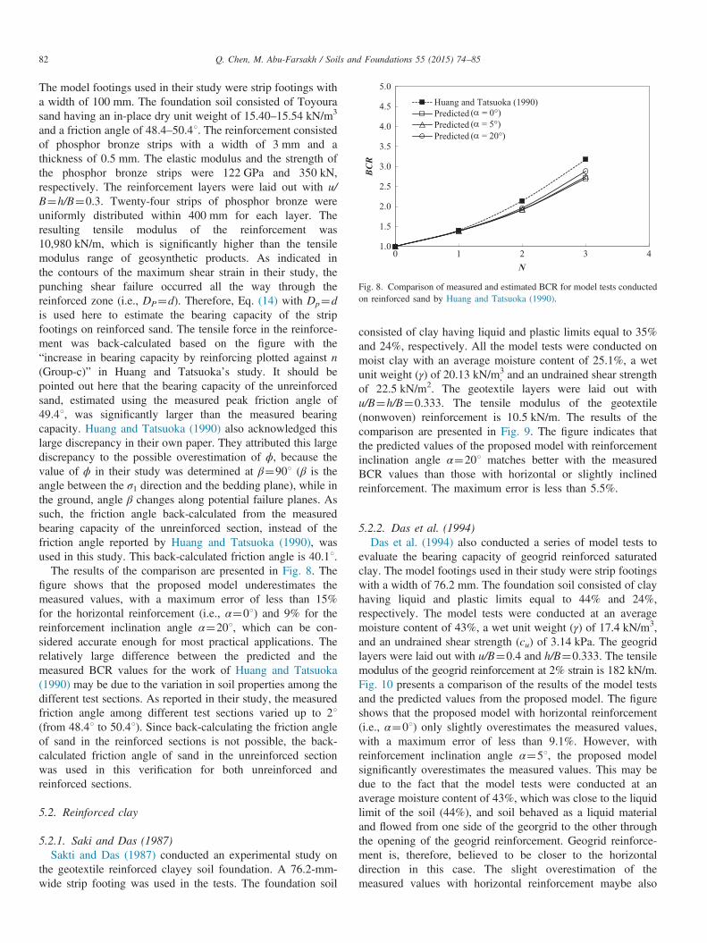
The model footings used in their study were strip footings witha width of 100 mm. The foundation soil consisted of Toyourasand having an in-place dry unit weight of 15.40–15.54 kN/m3
and a friction angle of 48.4–50.41. The reinforcement consistedof phosphor bronze strips with a width of 3 mm and athickness of 0.5 mm. The elastic modulus and the strength ofthe phosphor bronze strips were 122 GPa and 350 kN,respectively. The reinforcement layers were laid out with u/B¼h/B¼0.3. Twenty-four strips of phosphor bronze wereuniformly distributed within 400 mm for each layer. Theresulting tensile modulus of the reinforcement was10,980 kN/m, which is significantly higher than the tensilemodulus range of geosynthetic products. As indicated inthe contours of the maximum shear strain in their study, thepunching shear failure occurred all the way through thereinforced zone (i.e., DP¼d). Therefore, Eq. (14) with Dp¼dis used here to estimate the bearing capacity of the stripfootings on reinforced sand. The tensile force in the reinforce-ment was back-calculated based on the figure with the“increase in bearing capacity by reinforcing plotted against n(Group-c)” in Huang and Tatsuoka’s study. It should bepointed out here that the bearing capacity of the unreinforcedsand, estimated using the measured peak friction angle of49.41, was significantly larger than the measured bearingcapacity. Huang and Tatsuoka (1990) also acknowledged thislarge discrepancy in their own paper. They attributed this largediscrepancy to the possible overestimation of ϕ, because thevalue of ϕ in their study was determined at β¼901 (β is theangle between the σ1 direction and the bedding plane), while inthe ground, angle β changes along potential failure planes. Assuch, the friction angle back-calculated from the measuredbearing capacity of the unreinforced section, instead of thefriction angle reported by Huang and Tatsuoka (1990), wasused in this study. This back-calculated friction angle is 40.11.
The results of the comparison are presented in Fig. 8. Thefigure shows that the proposed model underestimates themeasured values, with a maximum error of less than 15%for the horizontal reinforcement (i.e., α¼01) and 9% for thereinforcement inclination angle α¼201, which can be con-sidered accurate enough for most practical applications. Therelatively large difference between the predicted and themeasured BCR values for the work of Huang and Tatsuoka(1990) may be due to the variation in soil properties among thedifferent test sections. As reported in their study, the measuredfriction angle among different test sections varied up to 21(from 48.41 to 50.41). Since back-calculating the friction angleof sand in the reinforced sections is not possible, the back-calculated friction angle of sand in the unreinforced sectionwas used in this verification for both unreinforced andreinforced sections.
5.2. Reinforced clay
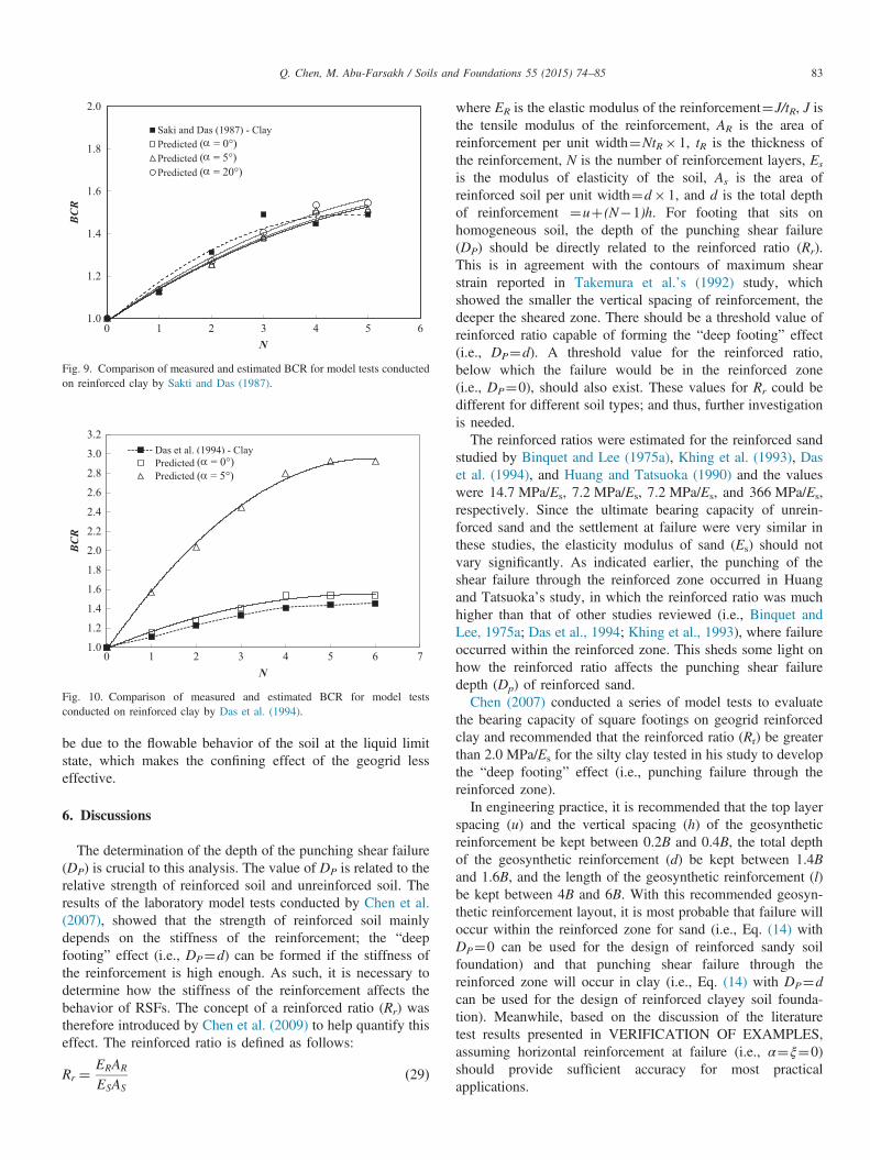
5.2.1. Saki and Das (1987)Sakti and Das (1987) conducted an experimental study on
the geotextile reinforced clayey soil foundation. A 76.2-mm-wide strip footing was used in the tests. The foundation soil
consisted of clay having liquid and plastic limits equal to 35%and 24%, respectively. All the model tests were conducted onmoist clay with an average moisture content of 25.1%, a wetunit weight (γ) of 20.13 kN/m3
, and an undrained shear strengthof 22.5 kN/m2. The geotextile layers were laid out withu/B¼h/B¼0.333. The tensile modulus of the geotextile(nonwoven) reinforcement is 10.5 kN/m. The results of thecomparison are presented in Fig. 9. The figure indicates thatthe predicted values of the proposed model with reinforcementinclination angle α¼201 matches better with the measuredBCR values than those with horizontal or slightly inclinedreinforcement. The maximum error is less than 5.5%.
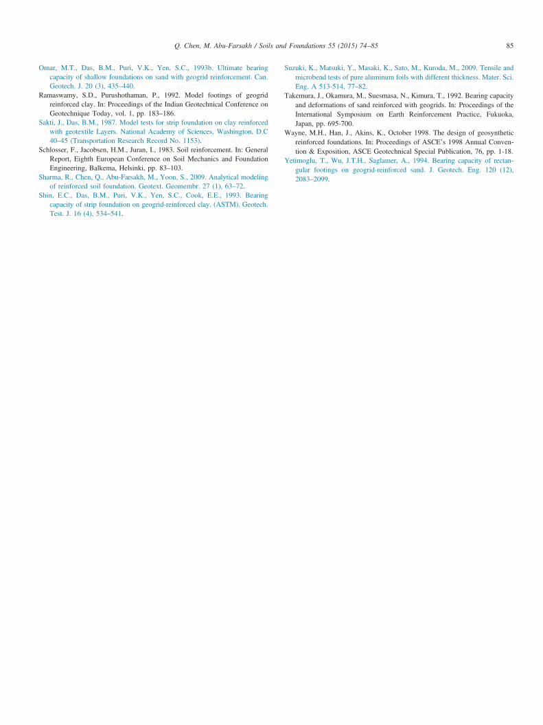
5.2.2. Das et al. (1994)Das et al. (1994) also conducted a series of model tests to
evaluate the bearing capacity of geogrid reinforced saturatedclay. The model footings used in their study were strip footingswith a width of 76.2 mm. The foundation soil consisted of clayhaving liquid and plastic limits equal to 44% and 24%,respectively. The model tests were conducted at an averagemoisture content of 43%, a wet unit weight (γ) of 17.4 kN/m3,and an undrained shear strength (cu) of 3.14 kPa. The geogridlayers were laid out with u/B¼0.4 and h/B¼0.333. The tensilemodulus of the geogrid reinforcement at 2% strain is 182 kN/m.Fig. 10 presents a comparison of the results of the model testsand the predicted values from the proposed model. The figureshows that the proposed model with horizontal reinforcement(i.e., α¼01) only slightly overestimates the measured values,with a maximum error of less than 9.1%. However, withreinforcement inclination angle α¼51, the proposed modelsignificantly overestimates the measured values. This may bedue to the fact that the model tests were conducted at anaverage moisture content of 43%, which was close to the liquidlimit of the soil (44%), and soil behaved as a liquid materialand flowed from one side of the georgrid to the other throughthe opening of the geogrid reinforcement. Geogrid reinforce-ment is, therefore, believed to be closer to the horizontaldirection in this case. The slight overestimation of themeasured values with horizontal reinforcement maybe also
1.0
1.2
1.4
1.6
1.8
2.0
2.2
2.4
2.6
2.8
3.0
3.2
0 1 2 3 4 5 6 7
BCR
N
Das et al. (1994) - ClayPredictedPredicted (5 deg)
( = 0°)( = 5°)
Fig. 10. Comparison of measured and estimated BCR for model testsconducted on reinforced clay by Das et al. (1994).
1.0
1.2
1.4
1.6
1.8
2.0
0 1 2 3 4 5 6
BCR
N
Saki and Das (1987) - ClayPredictedPredicted (5 deg)Predicted (20 deg)
( = 0°)( = 5°)( = 20°)
Fig. 9. Comparison of measured and estimated BCR for model tests conductedon reinforced clay by Sakti and Das (1987).
Q. Chen, M. Abu-Farsakh / Soils and Foundations 55 (2015) 74–85 83
be due to the flowable behavior of the soil at the liquid limitstate, which makes the confining effect of the geogrid lesseffective.
6. Discussions
The determination of the depth of the punching shear failure(DP) is crucial to this analysis. The value of DP is related to therelative strength of reinforced soil and unreinforced soil. Theresults of the laboratory model tests conducted by Chen et al.(2007), showed that the strength of reinforced soil mainlydepends on the stiffness of the reinforcement; the “deepfooting” effect (i.e., DP¼d) can be formed if the stiffness ofthe reinforcement is high enough. As such, it is necessary todetermine how the stiffness of the reinforcement affects thebehavior of RSFs. The concept of a reinforced ratio (Rr) wastherefore introduced by Chen et al. (2009) to help quantify thiseffect. The reinforced ratio is defined as follows:
Rr ¼ERAR
ESASð29Þ
where ER is the elastic modulus of the reinforcement¼J/tR, J isthe tensile modulus of the reinforcement, AR is the area ofreinforcement per unit width¼NtR� 1, tR is the thickness ofthe reinforcement, N is the number of reinforcement layers, Es
is the modulus of elasticity of the soil, As is the area ofreinforced soil per unit width¼d� 1, and d is the total depthof reinforcement ¼uþ (N�1)h. For footing that sits onhomogeneous soil, the depth of the punching shear failure(DP) should be directly related to the reinforced ratio (Rr).This is in agreement with the contours of maximum shearstrain reported in Takemura et al.’s (1992) study, whichshowed the smaller the vertical spacing of reinforcement, thedeeper the sheared zone. There should be a threshold value ofreinforced ratio capable of forming the “deep footing” effect(i.e., DP¼d). A threshold value for the reinforced ratio,below which the failure would be in the reinforced zone(i.e., DP¼0), should also exist. These values for Rr could bedifferent for different soil types; and thus, further investigationis needed.The reinforced ratios were estimated for the reinforced sand
studied by Binquet and Lee (1975a), Khing et al. (1993), Daset al. (1994), and Huang and Tatsuoka (1990) and the valueswere 14.7 MPa/Es, 7.2 MPa/Es, 7.2 MPa/Es, and 366 MPa/Es,respectively. Since the ultimate bearing capacity of unrein-forced sand and the settlement at failure were very similar inthese studies, the elasticity modulus of sand (Es) should notvary significantly. As indicated earlier, the punching of theshear failure through the reinforced zone occurred in Huangand Tatsuoka’s study, in which the reinforced ratio was muchhigher than that of other studies reviewed (i.e., Binquet andLee, 1975a; Das et al., 1994; Khing et al., 1993), where failureoccurred within the reinforced zone. This sheds some light onhow the reinforced ratio affects the punching shear failuredepth (Dp) of reinforced sand.Chen (2007) conducted a series of model tests to evaluate
the bearing capacity of square footings on geogrid reinforcedclay and recommended that the reinforced ratio (Rr) be greaterthan 2.0 MPa/Es for the silty clay tested in his study to developthe “deep footing” effect (i.e., punching failure through thereinforced zone).In engineering practice, it is recommended that the top layer
spacing (u) and the vertical spacing (h) of the geosyntheticreinforcement be kept between 0.2B and 0.4B, the total depthof the geosynthetic reinforcement (d) be kept between 1.4Band 1.6B, and the length of the geosynthetic reinforcement (l)be kept between 4B and 6B. With this recommended geosyn-thetic reinforcement layout, it is most probable that failure willoccur within the reinforced zone for sand (i.e., Eq. (14) withDP¼0 can be used for the design of reinforced sandy soilfoundation) and that punching shear failure through thereinforced zone will occur in clay (i.e., Eq. (14) with DP¼dcan be used for the design of reinforced clayey soil founda-tion). Meanwhile, based on the discussion of the literaturetest results presented in VERIFICATION OF EXAMPLES,assuming horizontal reinforcement at failure (i.e., α¼ξ¼0)should provide sufficient accuracy for most practicalapplications.

Q. Chen, M. Abu-Farsakh / Soils and Foundations 55 (2015) 74–8584
To fully capture the effect of the reinforced ratio on thepunching shear failure depth (Dp) for different types of soil,however, a comprehensive numerical parametric study needsto be performed. This can be done by varying the soilproperties (e.g., Es, c, and ϕ) and the reinforcement config-uration/properties (e.g., u, h, d, l, and J) in the numericalsimulation. Design charts can then be developed to assistengineers in estimating the depth of the punching shear failure(Dp).
7. Conclusions
A general failure mode for RSFs was proposed in this studybased on previous studies conducted by the authors and the testresults from the literature study. The limit equilibrium stabilityanalysis, considering both the confinement effect and themembrane effect of the reinforcements, was conducted onthe proposed failure mechanism of RSFs. A new unifiedbearing capacity formula, that incorporated the contributionof reinforcements to the increase in the ultimate bearingcapacity, was then developed for RSFs. The estimated ultimatebearing capacity using the proposed model was compared withthe results of model tests reported in the literature by differentresearchers for strip footings on both reinforced sand and clay.The proposed analytical model gave a good prediction of theexperimental results reported in the literature.
The literature study indicated that the depth of the punchingshear failure (DP) zone depends on the relative strength of thereinforced soil layer and the underlying unreinforced soil layer.The reinforced ratio (Rr) can be used to determine the depth ofthe punching shear failure zone (DP). There should be athreshold value for the reinforced ratio (Rr) capable of formingthe “deep footing” effect. A threshold value for the reinforcedratio, below which the failure would be in the reinforced zone(i.e., DP¼0), should also exist.
References
Abu-Farsakh, M., Chen, Q., Sharma, R., 2013. An experimental evaluation ofthe behavior of footings on geosynthetic-reinforced sand. Soils Found. 53(2), 335–348.
Abu-Farsakh, M., Chen, Q., Sharma, R., Zhang, X., 2008. Large-scale modelfooting tests on geogrid reinforced foundation and marginal embankmentsoils. Geotech. Test. J. 31 (5), 413–423.
Adams, M.T., Collin, J.G., 1997. Large model spread footing load tests ongeosynthetic reinforced soil foundations. J. Geotech. Geoenviron. Eng. 123(1), 66–72.
Akinmusuru, J.O., Akinbolade, J.A., 1981. Stability of loaded footing onreinforced soil. J. Geotech. Eng. 107 (6), 819–827.
Bera, A.K., Ghosh, A., Ghosh, A., 2005. Regression model for bearingcapacity of a square footing on reinforced pond ash. Geotext. Geomembr.23 (3), 261–285.
Binquet, J., Lee, K.L., 1975a. Bearing capacity tests on reinforced earth slabs.J. Geotech. Eng. Div. 101 (GT12), 1241–1255.
Binquet, J., Lee, K.L., 1975b. Bearing capacity analysis on reinforced earthslabs. J. Geotech. Eng. Div. 101 (GT12), 1257–1276.
Caquot, A., Kerisel, L., 1948. Tables for the Calculation of Passive Pressure.Gauthier-Villars, Imprimeur-Editeur, Paris (Active Pressure, and BearingCapacity of Foundations).
Chakraborty, M., Kumar, J., 2014. Bearing capacity of circular foundationsreinforced with geogrid sheets. Soils Found.http://dxdoi.org/10.1016/j.sandf.2014.06.013.
Chen, Q., 2007. An Experimental Study on Characteristics and Behavior ofReinforced Soil Foundation. Ph.D. Dissertation, Louisiana State Univer-sity, Baton Rouge, USA.
Chen, Q., Abu-Farsakh, M., 2011. Field Performance of a New Approach SlabSystem. ASCE Geotechnical Special Publication No. 224. GeotechnicalRisk Assessment and Management, pp. 1036-1043.
Chen, Q., Abu-farsakh, M., Sharma, R., Zhang, X., 2007. Laboratoryinvestigation of behavior of foundations on geosynthetic-reinforced clayeysoil. Transp. Res. Record J. Transp. Res. Board 2004, 28–38.
Chen, Q., Abu-Farsakh, M., Sharma, R., 2009. Experimental and analyticalstudies of reinforced crushed limestone. Geotext. Geomembr. 27 (5),357–367.
Das, B.M., Shin, E.C., Omar, M.T., 1994. The bearing capacity of surface stripfoundations on geogrid reinforced sand and clay—a comparative study.Geotech. Geol. Eng. 12 (1), 1–14.
Das, B.M., 1999. Shallow Foundations: Bearing Capacity and Settlement.CRC Press, Boca Raton.
DeMerchant, M.R., Valsangkar, A.J., Schriver, A.B., 2002. Plate load tests ongeogrid-reinforced expanded shale lightweight aggregate. Geotext. Geo-membr. 20, 173–190.
Demir, A., Laman, M., Yildiz, A., Ornek, M., 2013. Large scale field tests ongeogrid-reinforced granular fill underlain by clay soil. Geotext. Geomembr.38, 1–15.
Fragaszy, J.R., Lawton, E., 1984. Bearing capacity of reinforced sandsubgrades. (ASCE). J. Geotech. Eng. 110 (10), 1500–1507.
Gabr, M.A., Dodson, R., Collin, J.G., 1998. A study of stress distribution ingeogrid-reinforced sand. In: Proceedings of Geosynthetics in FoundationReinforcement and Erosion Control Systems, ASCE Geotechnical SpecialPublication, 76, pp. 62–76.
Ghosh, A., Ghosh, A., Bera, A.K., 2005. Bearing capacity of square footing onpond ash reinforced with jute–geotextile. Geotext. Geomembr. 23 (2),144–173.
Guido, V.A., Chang, D.K., Sweeny, M.A., 1986. Comparison of geogrid andgeotextile reinforced slabs. Can. Geotech. J. 20, 435–440.
Huang, C.C., Tatsuoka, F., 1990. Bearing capacity reinforced horizontal sandyground. Geotext. Geomembr. 9, 51–82.
Huang, C.C., Menq, F.Y, 1997. Deep-footing and wide-slab effects in reinforcedsandy ground. (ASCE). J. Geotech. Geoenviron. Eng. 123 (1), 30–36.
Ingold, T.S., Miller, K.S., 1982. Analytical and laboratory investigation ofreinforced clay. In: Proceedings of the Second International Conference onGeotextiles, vol. 3, pp. 587–592.
James, R., Raymond, G., 2002. Strain/load on geogrid reinforcement ofaggregates below shallow footings. In: Proceedings of the 55th CanadianGeotechnical and 3rd Joint IAH-CNC and CGS Groundwater SpecialtyConferences, Niagara Falls, ON, pp. 783–790.
Khing, K.H., Das, B.M., Puri, V.K., Cook, E.E., Yen, S.C., 1993. The bearingcapacity of a strip foundation on geogrid reinforced sand. Geotext.Geomembr. 12, 351–361.
Kumar, A., Saran, S., 2003. Bearing capacity of rectangular footing onreinforced soil. Geotech. Geol. Eng. 21, 201–224.
Latha, G.M., Somwanshi, A., 2009. Bearing capacity of square footings ongeosynthetic reinforced sand. Geotext. Geomembr. 27 (4), 281–294.
Lavasan, A.A., Ghazavi, M., 2012. Behavior of closely spaced square andcircular footings on reinforced sand. Soils Found. 52 (1), 160–167.
Kurian, N.P., Beena, K.S., Kumar, R.K., 1997. Settlement of reinforced sandin foundations. (ASCE). J. Geotech. Geoenviron. Eng. 123 (9), 818–827.
Mandal, J.N., Sah, H.S., 1992. Bearing capacity tests on geogrid-reinforcedclay. Geotext. Geomembr. 11 (3), 327–333.
Michalowski, R.L., 2004. Limit loads on reinforced foundation soils. J.Geotech. Geoenviron. Eng. 130 (4), 381–390.
Meyerhof, G.G., Hanna, A.M., 1978. Ultimate bearing capacity of foundationson layered soils under inclined load. Can. Geotech. J 15 (4), 565–572.
Omar, M.T., Das, B.M., Yen, S.C., Puri, V.K., Cook, E.E., 1993a. Ultimatebearing capacity of rectangular foundations on geogrid-reinforced sand.Geotech. Test J 16 (2), 246–252.
Q. Chen, M. Abu-Farsakh / Soils and Foundations 55 (2015) 74–85 85
Omar, M.T., Das, B.M., Puri, V.K., Yen, S.C., 1993b. Ultimate bearingcapacity of shallow foundations on sand with geogrid reinforcement. Can.Geotech. J. 20 (3), 435–440.
Ramaswamy, S.D., Purushothaman, P., 1992. Model footings of geogridreinforced clay. In: Proceedings of the Indian Geotechnical Conference onGeotechnique Today, vol. 1, pp. 183–186.
Sakti, J., Das, B.M., 1987. Model tests for strip foundation on clay reinforcedwith geotextile Layers. National Academy of Sciences, Washington, D.C40–45 (Transportation Research Record No. 1153).
Schlosser, F., Jacobsen, H.M., Juran, I., 1983. Soil reinforcement. In: GeneralReport, Eighth European Conference on Soil Mechanics and FoundationEngineering, Balkema, Helsinki, pp. 83–103.
Sharma, R., Chen, Q., Abu-Farsakh, M., Yoon, S., 2009. Analytical modelingof reinforced soil foundation. Geotext. Geomembr. 27 (1), 63–72.
Shin, E.C., Das, B.M., Puri, V.K., Yen, S.C., Cook, E.E., 1993. Bearingcapacity of strip foundation on geogrid-reinforced clay. (ASTM). Geotech.Test. J. 16 (4), 534–541.
Suzuki, K., Matsuki, Y., Masaki, K., Sato, M., Kuroda, M., 2009. Tensile andmicrobend tests of pure aluminum foils with different thickness. Mater. Sci.Eng. A 513-514, 77–82.
Takemura, J., Okamura, M., Suesmasa, N., Kimura, T., 1992. Bearing capacityand deformations of sand reinforced with geogrids. In: Proceedings of theInternational Symposium on Earth Reinforcement Practice, Fukuoka,Japan, pp. 695-700.
Wayne, M.H., Han, J., Akins, K., October 1998. The design of geosyntheticreinforced foundations. In: Proceedings of ASCE’s 1998 Annual Conven-tion & Exposition, ASCE Geotechnical Special Publication, 76, pp. 1-18.
Yetimoglu, T., Wu, J.T.H., Saglamer, A., 1994. Bearing capacity of rectan-gular footings on geogrid-reinforced sand. J. Geotech. Eng. 120 (12),2083–2099.
Related Documents