X-ray Interferometry Webster Cash University of Colorado

Ultimate astronomicalimaging
Aug 15, 2015
Welcome message from author
This document is posted to help you gain knowledge. Please leave a comment to let me know what you think about it! Share it to your friends and learn new things together.
Transcript

X-ray Interferometry
Webster CashUniversity of Colorado

Collaborators
• Ann Shipley, Karen Doty, Randy McEntaffer, & Steve Osterman at CU
• Nick White – Goddard• Marshall Joy – Marshall • David Windt and Steve Kahn - Columbia• Mark Schattenburg - MIT• Dennis Gallagher – Ball Aerospace
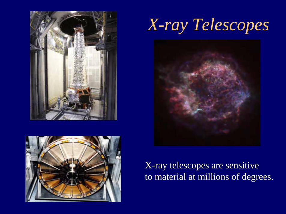
X-ray Telescopes
X-ray telescopes are sensitiveto material at millions of degrees.

Capella 0.1”

Capella 0.01”

Capella 0.001”

Capella 0.0001”

Capella 0.00001”

Capella 0.000001”

AR LacSimulation @ 100µas

AGN Accretion DiskSimulations @ 0.1µas
C. Reynolds, U. Colorado
M. Calvani, U. Padua

Need Resolution and Signal
If we are going to do this, we need to support two basic capabilities:
• Signal • Resolution
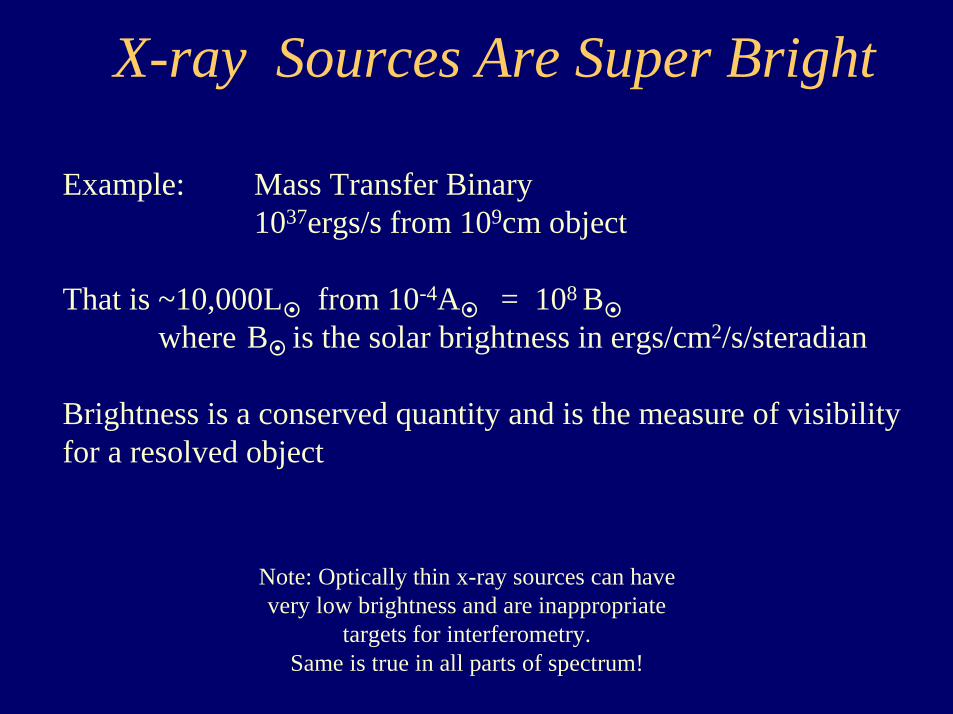
X-ray Sources Are Super Bright
Example: Mass Transfer Binary1037ergs/s from 109cm object
That is ~10,000L�
from 10-4A�
= 108 B�
where B�
is the solar brightness in ergs/cm2/s/steradian
Brightness is a conserved quantity and is the measure of visibility for a resolved object
Note: Optically thin x-ray sources can have very low brightness and are inappropriate
targets for interferometry. Same is true in all parts of spectrum!

Minimum Resolution
Status of X-ray Optics
• Modest Resolution– 0.5 arcsec telescopes– 0.5 micron microscopes
• Severe Scatter Problem– Mid-Frequency Ripple
• Extreme Cost– Millions of Dollars Each– Years to Fabricate

Classes of X-ray Interferometers
Dispersive
Non-Dispersive
Elements are Crystals or Gratings
Elements are Mirrors & Telescopes

Achieving High Resolution
R=λ/20000DR in Arcsecλ in AngstromsD in Meters
Michelson Stellar Interferometer
Use Interferometry to Bypass Diffraction Limit

Creating Fringes
Requirements• Path Lengths Nearly Equal• Plate Scale Matched to Detector
Pixels• Adequate Stability• Adequate Pointing• Diffraction Limited Optics
dD

θδ
sin1 =B
( )θ2cos12 BB =
( )[ ] θδθ
θδ sin2sin
2cos121 =−=−= BBOPD
θλδsin20
<
( )θθ
λcossin20
<Baselined
( )θ
λ2sin20
<focald
Pathlength Tolerance Analysis at Grazing Incidence
A1 A2
S1S2
δδδδ
A1 & A2 in Phase Here
C
θ
θ
θ
Β1Β2θ If OPD to be < λ/10 then

A Simple X-ray Interferometer
Flats Beams Cross
Detector

Wavefront Interference
θ=d/L
λ=θs (where s is fringe spacing)
dLs λ=s

Optics
Each Mirror Was AdjustableFrom Outside Vacuum
System was covered by thermal shroud

Stray Light Facility MSFC
16m
Source, filter and slit
100m
Interferometer CCD
Used Long Distance ToMaximize Fringe Spacing

CCD Image @ 1.25keV
2 Beams Separate 2 Beams Superimposed
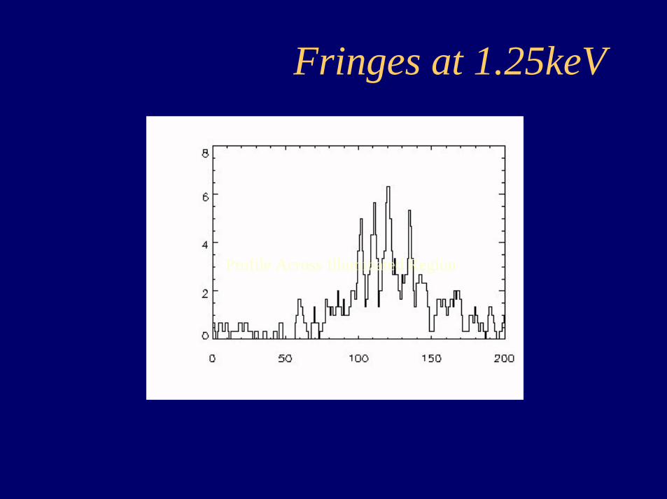
Fringes at 1.25keV
Profile Across Illuminated Region

Test Chamber at CU
Ten Meter Long VacuumChamber for Testing
Came on-line early May
EUV results goodUpgrade to x-ray next

Actual Image at 30.4nm
Image of SlitReconstructed from 4 azimuths

MAXIMThe Micro Arcsecond X-ray Imaging Mission
Webster Cash ColoradoNicholas White GoddardMarshall Joy Marshall
http://maxim.gsfc.nasa.gov
PLUS Contributions from the Maxim Team

Target Class Goal
Resolve the corona of nearby stars: Are other coronal structures like the solar corona? Resolve the winds of OB stars: What kind of shocks drive the x-ray emission?Resolve pre-main sequence stars: How does coronal activity interact with disk?Image of center of Milky Way: Detect and resolve accretion disk? Detailed images of LMC, SMC, M31: Supernova morphology and star formation in other settingsImage jets, outflows and BLR from AGN: Follow jet structure, search for scattered emission from BLRDetailed view of starbursts: Resolve supernovae and outflowsMap center of cooling flows in clusters: Resolve star formation regions?Detailed maps of clusters at high redshift: Cluster evolution, cooling flows
Image Event Horizons in AGNS: Probe Extreme Gravity Limit
Maxim:A Few Science Goals

Flats Held in PhaseSample Many Frequencies

As More Flats Are UsedPattern Approaches Image
2 4 8
16 3212

On the left is the probability distribution function for two sources in the same field of view. The central source has an energy half that of the source that is displaced to the lower left. The image on the right shows 9000 total events for this system with the lower energy source having twice the intensity of the higher energy source. Even though the higher energy source is in the first maxima of the other, the two can still be easily distinguished.

Clockwise from upper left: Probability distribution; 100 photons randomly plotted; 9000 photons; and 5000 photons.

These figures show the probability distribution for the 6keV portion of the continuum and the contribution of photons with energies between 5-6keV to the data simulation.

These figures show the probability distribution for the 1keV portion of the continuum and the contribution of photons with energies between 0-1keV to the data simulation.

The probability distribution on the left represents a continuum of energies between 1keV and 6keV. In the right figure, 16000 random events were recorded according to this distribution.
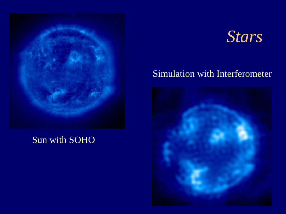
Stars
Simulation with Interferometer
Sun with SOHO

AGN with Jet
3C273 with Chandra
Simulation with Interferometer

Four Difficult Areas • Fabrication of Interferometer
• Formation Flying– Hold Detector Craft in Position
• Pointing– Hold Interferometer on Target
• Internal Metrology– Hold Mirrors Flat and In Position

Maxim
0.1µas Resolution10,000cm2 Effective Area0.4-7.0 keV
“The Black Hole Imager”
DETECTORSPACECRAFT
CONVERGERSPACECRAFT
200M
COLLECTORSPACECRAFT(32 PLACESEVENLY SPACED)
10KM
5000KM
CONSTELLATIONBORESIGHT

Maxim Pathfinder100µas Resolution100cm2 Effective Area0.4-2.0keV + 6keV
Two SpacecraftFormation Flying at450km Separation

2.5m10
m
Optics SpacecraftCarries: X-ray Interferometers
Finder X-ray Telescopes2 Visible Light InterferometersLaser Ranging System
Size: 2.5x2.5x10mPitch&Yaw Stability: 3x10⁻⁴ arcsecPitch&Yaw Knowledge: 3x10⁻⁵ arcsecRoll Stability: 20 arcsecPosition Stability: -----
Detector SpacecraftCarries: X-ray Detector Array
Laser Retro ReflectorsPrecision Thrusters
Size: 1x1x1mPitch&Yaw Stability: 20 arcsecRoll Stability: 20 arcsecLateral Stability: 5mmLateral Knowledge: 50 micronsFocal Stability: 10 meters
1m
1m
Sepa
ratio
n 4
50km
Maxim Pathfinder Mission Concept

Prime Interferometer
Wolter Telescope
Yaw Sensor
Pitch Sensor
Optics CraftFront View

Solution to Pointing Problem
Consider, instead, line F.Mount the visible light interferometer on structuresat the ends of line F. They then maintain 1nm precisionwrt to guide star that lies perpendicular to F. This definespointing AND maintains lateral position of convergers. (40pm not needed in D and E after all.)A, B, C, D and E all maintain position relative to F.
AB
C
D
EF
Visible light wavefrontfrom distant star

Detector
• Energy Resolution Necessary for Fringe Inversion
• CCD is adequate• To get large field of view use imaging
quantum calorimeter

MetrologyTightest Tolerance is Separation of Entrance Apertures
d = λ/20θ for tenth fringe stability
At 1keV and 2deg, d=1.7nmAt 6keV and 0.5deg, d=1.1nm
Requires active thermal control and internal alignment

Laser
Beamsplitter
Collimated BeamsCross at 450km
Collimator
Laser BeamSplit and Collimated
Optics Craft450km toDetector Craft

Coherent Beams from Optics Craft
Interference PatternLens
Interference PatternReduced Onto CCD
Detection of Patternat Detector Craft
Fringes have 14cm period at 450km

PointingNeed stability and information wrt to the celestial sphere at level of required resolution.
L2 or Fly-away orbit probably necessary
Baseline design calls for two stellar interferometers.One each for pitch and yawSIM class interferometers more than adequate

Delta IV (H) 5m diameter x 19.8m long
Launch Fairing Removed
Detector Spacecraft(2.2m)
Optics Instruments(10m)
Optic Spacecraft Systems(2.2m)
Baffling
LAUNCHCONFIGURATION
15.5 m
16.4 m
Payload
Spacecraft

ORBIT CONFIGURATION
Optic Spacecraft
Detector Spacecraft
Solar Array(7 m^2, projected area)

Stowed
Orbit
Payload
Spacecraft
Spacecraft Subsystems are mounted inthis volume
FixedSolar Array
(6m^2 shown)
DETECTOR SPACECRAFT

MAXIM Trajectory in Solar Rotating Coordinates

Maxim Pathfinder

Maxim Design
DETECTORSPACECRAFT
CONVERGERSPACECRAFT
200M
COLLECTORSPACECRAFT(32 PLACESEVENLY SPACED)
10KM
5000KM
CONSTELLATIONBORESIGHT
Hub Spacecraft
SPACECRAFTDELAY LINE
Hub Craft Converger Craft Delay Craft
Light from Star

Full Maxim
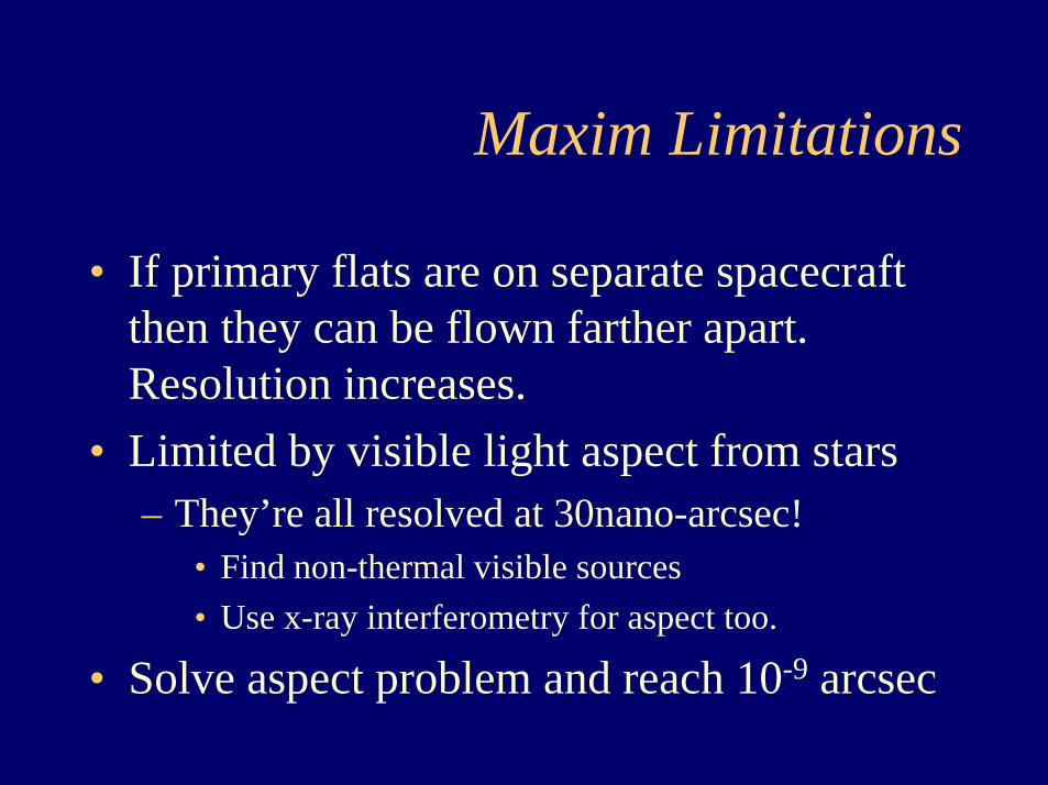
Maxim Limitations
• If primary flats are on separate spacecraft then they can be flown farther apart. Resolution increases.
• Limited by visible light aspect from stars– They’re all resolved at 30nano-arcsec!
• Find non-thermal visible sources• Use x-ray interferometry for aspect too.
• Solve aspect problem and reach 10-9 arcsec
Integrated System Modeling
Ball Aerospace Technologies Corporation
M. LieberD. Gallagher
Will lead to single most important tool in developmentand definition of x-ray interferometry
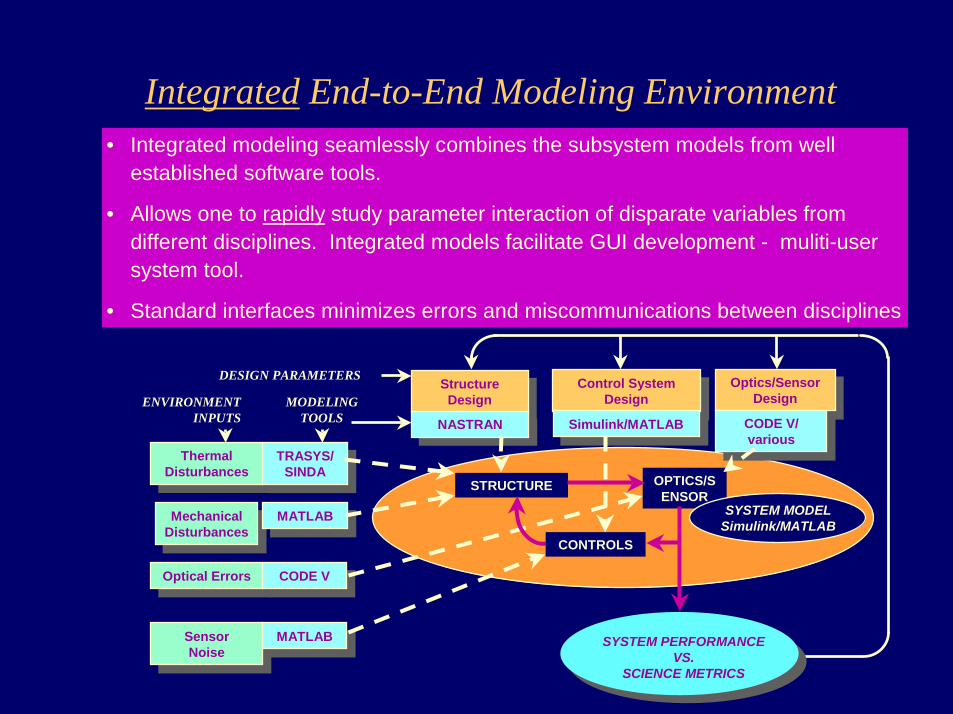
• Integrated modeling seamlessly combines the subsystem models from well established software tools.
• Allows one to rapidly study parameter interaction of disparate variables from different disciplines. Integrated models facilitate GUI development - muliti-user system tool.
• Standard interfaces minimizes errors and miscommunications between disciplines
Structure Design
Structure Design Control System
Design
Control System Design Optics/Sensor
Design
Optics/Sensor Design
NASTRANNASTRAN Simulink/MATLABSimulink/MATLAB CODE V/ various
CODE V/ various
STRUCTURE OPTICS/SENSOR
ThermalDisturbances
ThermalDisturbances
MechanicalDisturbances
MechanicalDisturbances
Optical ErrorsOptical Errors
TRASYS/SINDA
TRASYS/SINDA
MATLABMATLAB
CODE VCODE V
MODELINGTOOLS
DESIGN PARAMETERS
ENVIRONMENTINPUTS
SYSTEM PERFORMANCEVS.
SCIENCE METRICS
SensorNoise
SensorNoise MATLABMATLAB
SYSTEM MODELSimulink/MATLAB
CONTROLS
Integrated End-to-End Modeling Environment

Example of MAXIM Pathfinder
Maxim Pathfinder IM
2
1
Wavefront & tilt sensor models
Structural dynamics
Telescope mechanism tip/tilt and
wavefront control systems
Spacecraft attitude control
Signal processing
Optics model
Image processing
Imaging sensor models3
2
1
In1
sav_psf
To Workspace2Sparse secondary mirror
array
Sparse primary mirror
array
Optical raybundle1
RB offsets
Deform mapOut3
Offsets1
RB offsets
Deform mapOut3
Offsets
Image plane
[ttt,uuu]
[ttt,uuu2]
u_surf2
u_surf1
1Out1
Sparse reflective mirror4
Sparse reflective mirror3
Sparse reflective mirror2
Sparse reflective mirror1{a1}
{b1}
[c4]
[c3]
[c2]
[c1]
{b1}{a1}[c4]
[c3]
[c2]
[c1]
2Opticsmotion
1Ray bundle
Optical subsystem
• Structures, optics, controls, signal processing, disturbances

Optical Toolbox:Key Element of Optical Performance Modeling
• Geometric ray trace• Diffraction analysis (PSF outputs)• Easy introduction of mirror distortions from thermal or
vibration• Optics tied to NASTRAN structural model• Active control modeling of metrology system and active
optics• Interfaces with imaging and detection modules
sav_psf
To Workspace2Sparse secondary mirror
array
Sparse primary mirror
array
Optical raybundle1
RB offsets
Deform mapOut3
Offsets1
RB offsets
Deform mapOut3
Offsets
Image plane
[ttt,uuu]
[ttt,uuu2]
u_surf2
u_surf1
See next slide

MAXIM Pathfinder PSFs with Different Number of Optical Elements
2 segments
4 segments
32 segments
PSF Image Log image

MAXIM Physical Model
MAXIM Integrated Model
Celestrial objects
Detector S/C
Converger and Delay Line S/C
Collectors & Hub S/C
Command and Control

MAXIM System Modeling Leveraged From NASA and Other Programs
GSFC - Expertise and models for formation flying - FF lab
Optical metrology - Ball/GSFC Cross Enterprise contract, Ball/JPL Starlight program
Integrated modeling environment and MATLAB/Simulink toolset -NGST, TPF, VLT
Wavefront control - see next slide

Example Wavefront Control Modeling -Initial Phase Map of NGST
10 20 30 40 50 60
10
20
30
40
50
60
10 20 30 40 50 60
10
20
30
40
50
60
[ x-decenter y-decenter piston tip tilt clocking]
• RMS random = primary segments [ 1e-4 1e-4 4e-5 1e-5 1e-4 0]
• Secondary = offsets
[ x-decenter y-decenter piston tip tilt clocking]
[ 1e-3 5e-4 1.5e-5 -3e-5 8e-4 0]
Random errors for 36 segments
1 2 3 4 5 6-4-202468
10x 10-4
x-decenter
y-decenter
piston
tip
tilt
• Wavefront control tools from NGST program and extensive work on phase retrieval by JPL

Status: X-ray Interferometry in NASA Planning
Structure and Evolution of the Universe (SEU) RoadmapMaxim Pathfinder Appears as Mid-Term Mission
Candidate Mission for 2008-2013Maxim Appears as Vision Mission
Candidate Mission for >2014
McKee-Taylor ReportNational Academy Decadal Review of AstronomyReleased May 19, 2000Prominently Recommends Technology Development
Money for X-ray Interferometry

“X-ray Roadmap” to Image a Black Hole
Do they exist?
2000 2008 2014 2020
X-ray Interferometry Demonstration
Black hole Imager!
Where are they?
Conditions in the inner disk
ROSATEinstein
ASCARXTE
Imaging
Spectroscopy
1000 times finer imagingMAXIM
Pathfinder
100 cm2
2 m baseline100 µarc sec
MAXIM
1000 cm2
100-1000 m baseline100 nas
Million times finer imaging
Chandra
100-1000 cm2
0.5 arc sec
XMMAstro-E
Constellation-X
3 m2
Indirect imaging via spectroscopy
Optimize MAXIM
Parameters
Spectrally Resolved
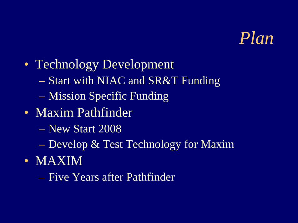
Plan• Technology Development
– Start with NIAC and SR&T Funding– Mission Specific Funding
• Maxim Pathfinder– New Start 2008– Develop & Test Technology for Maxim
• MAXIM– Five Years after Pathfinder

The Black Hole Disney, 1979
We have already found this black hole and will have thesepictures before 2020.
Related Documents