W h e r e I n n o v a t i o n F l o w s dynaBLEND ™ Liquid Polymer Blending System LISTED C www.fluiddynamics1.com

Welcome message from author
This document is posted to help you gain knowledge. Please leave a comment to let me know what you think about it! Share it to your friends and learn new things together.
Transcript
W h e r e I n n o v a t i o n F l o w s
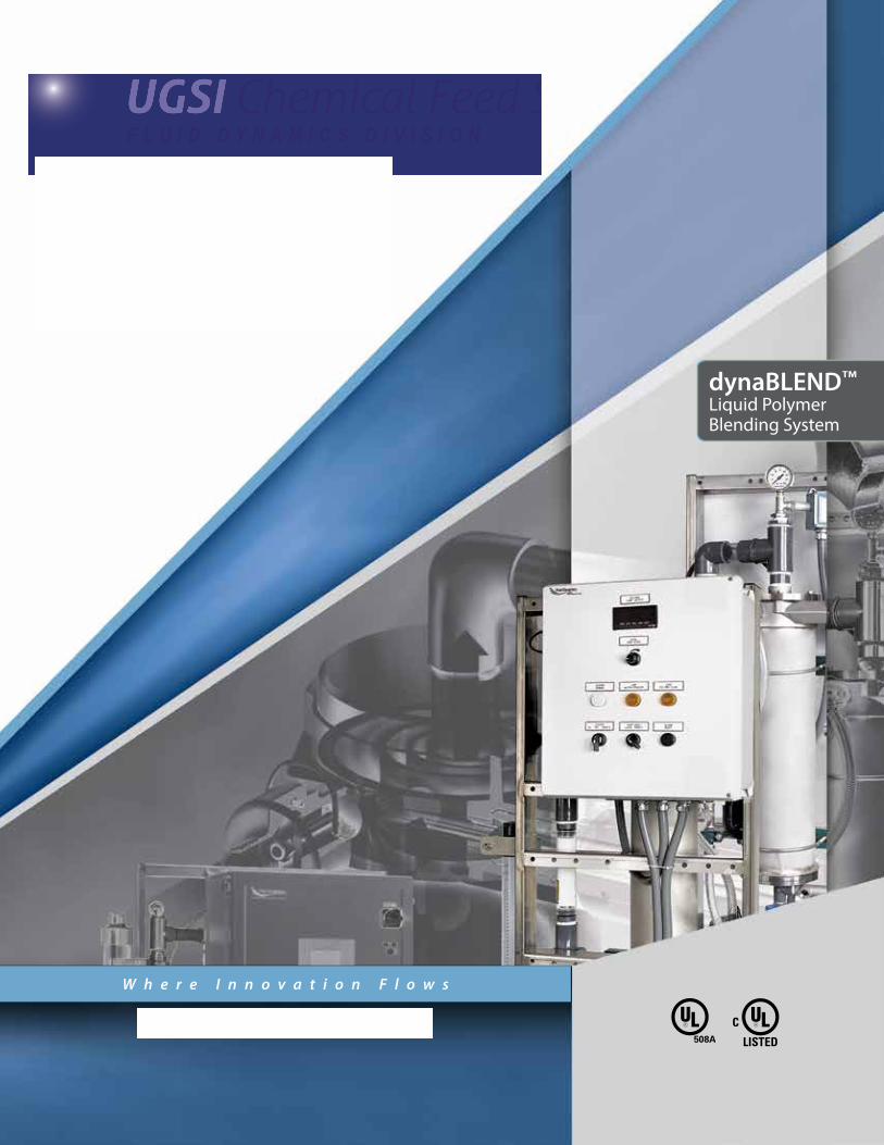
dynaBLEND™
Liquid PolymerBlending System
LISTED
Cwww.fluiddynamics1.com
klosee
Rectangle
klosee
Rectangle
klosee
Stamp
klosee
Rectangle
klosee
Stamp
klosee
Rectangle
klosee
Stamp

2
Liquid Polymer Blending
S Y S T E M
Polymer BlendingKnowing the critical requirements of polymer blending is the first step in understanding the numerous benefits of dynaBLEND™ technology. Over the years, the spectrum of available polymers has widened. Today there are more difficult-to-blend polymers than ever before. Some polymer blending systems work well on simple-to-blend polymers, but fail to effectively activate many other polymers.
As-Supplied or Concentrated Polymer—Polymer is a long chain molecule having positive (cationic), negative (anionic) or neutral (non-ionic) charge sites. In its as-supplied, concentrated form, the polymer is tightly coiled. In this state, the polymer is not susceptible to damage from high mixing energy.
Effects of Insufficient Mixing Energy—When insufficient mixing energy is applied, polymer gelling or agglomeration occurs, resulting in the charge sites not being fully exposed. Overdosing of polymer is required to achieve desired performance.
Effects of Overexposure to Mixing Energy—Overexposing polymer to mixing energy after initial activation will damage the fragile long chain molecule. Again, overdosing of polymer is required.
Fully Activated Polymer—Unwinding and elongating the coiled polymer molecule is necessary to expose the maximum number of charge sites to your process. The job of the polymer activation and blending system is to gently and thoroughly activate polymer. Fully elongated, undamaged polymer is the most active and effective form yet also the most fragile state. Continued exposure to mixing energy in this state will damage the fragile polymer.
The Way to Optimum Polymer Performance1. “Infinite Shear in Zero Time.” Apply ultra-high mixing energy at the point of initial polymer and water contact to prevent polymer gelling or agglomera-tion. At this time the polymer is coiled-up and not susceptible to damage.
2. Create the right environment. Polymer solution has proven to be the ideal environment for polymer activation, as opposed to raw water. Inject neat, concentrated polymer into polymer solution, not raw water.
3. Prolonged turbulence. Expose polymer to prolonged turbulence in order to complete the blending process gently and fully.
4. Avoid damaging mixing energy after the polymer is initially activated so as not to break the fragile molecular chain.
Our History In 1985 Fluid Dynamics developed the high- energy, non-mechanical dynaBLEND™ liquid polymer activation and blending technology.Immediately it proved to be a revolutionary and great improvement in polymer activation and blending performance. Today, the dynaBLEND™ system remains the most effective and reliable polymer activation technology—rendering mechanical blenders obsolete except for low flow applications.
klosee
Rectangle
* See Fluid Dynamics warranty for further details.
3
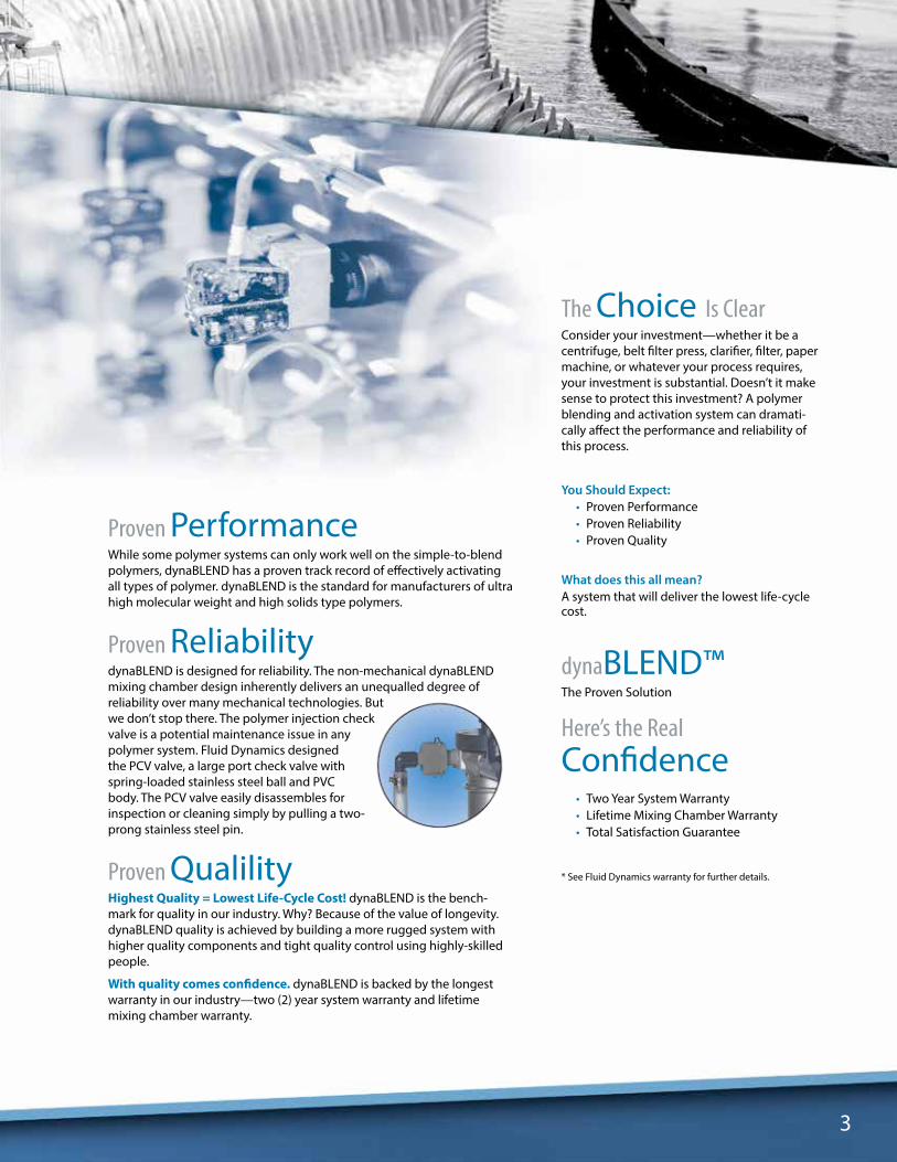
Proven PerformanceWhile some polymer systems can only work well on the simple-to-blend polymers, dynaBLEND has a proven track record of effectively activating all types of polymer. dynaBLEND is the standard for manufacturers of ultra high molecular weight and high solids type polymers.
Proven ReliabilitydynaBLEND is designed for reliability. The non-mechanical dynaBLEND mixing chamber design inherently delivers an unequalled degree of reliability over many mechanical technologies. But we don’t stop there. The polymer injection check valve is a potential maintenance issue in any polymer system. Fluid Dynamics designed the PCV valve, a large port check valve with spring-loaded stainless steel ball and PVC body. The PCV valve easily disassembles for inspection or cleaning simply by pulling a two-prong stainless steel pin.
Proven QualilityHighest Quality = Lowest Life-Cycle Cost! dynaBLEND is the bench-mark for quality in our industry. Why? Because of the value of longevity. dynaBLEND quality is achieved by building a more rugged system with higher quality components and tight quality control using highly-skilled people.
With quality comes confidence. dynaBLEND is backed by the longest warranty in our industry—two (2) year system warranty and lifetime mixing chamber warranty.
The Choice Is ClearConsider your investment—whether it be a centrifuge, belt filter press, clarifier, filter, paper machine, or whatever your process requires, your investment is substantial. Doesn’t it make sense to protect this investment? A polymer blending and activation system can dramati-cally affect the performance and reliability of this process.
You Should Expect:• Proven Performance• Proven Reliability• Proven Quality
What does this all mean?A system that will deliver the lowest life-cycle cost.
dynaBLEND™The Proven Solution
Here’s the RealConfidence
• Two Year System Warranty• Lifetime Mixing Chamber Warranty• Total Satisfaction Guarantee

4
dynaBLEND Construction Features: A All Piping Components Rigidly
Mounted to Skid B Gusseted Uprights for Rigidity C NEMA 4X FRP Control Panel. Fluid
Dynamics is a ULC-Certified Panel Shop3
D Control Panel at Operator Eye-Level E Open Frame Design for Ease of
Accessibility Constructed of 304-SS F Sealtite for All Power Wiring
Basic dynaBLEND and Options:1 Metering Pump1
2 Calibration Column3a Loss of Polymer Flow Switch3b Polymer Flow Measurement (optional)4 Proprietary Design Polymer Check Valve5 Differential Pressure Switch6 Solenoid Valve7 Water Flow Measurement2
8 Liquid Filled SS Pressure Gauges9 Variable Orifice Water Control Valve
10 dynaBLEND Mixing Chamber11 Pressure Relief Valve
1 Can be peristaltic or progressing cavity.2 Can be Rotometer, Turbine Flow Meter or Magnetic Flow Meter.3 Optional stainless steel panels. Controls also available for
hazardous locations.
Water Inlet
Neat Polymer Inlet
ActivatedSolutionOutlet
7
Front View
Rear View
FI
PI
PI
FSL
PS
PS
PS
FE/FT
5
3a
2 8 9
11
10
4
17
6
8Flow Diagram
3b
C
D
E
F
A
B
Simply the Best Polymer System AvailabledynaBLEND L Series systems are designed to easily accept a wide range of flexible features and options. All dynaBLENDs utilize only the finest components, are built on all stainless steel frames and are designed to stand the test of time in extreme conditions and harsh environments.
dynaBLEND L4S-1200-5.0PS

5
Coiled Polymer
Activated Solution
Stage 1Initial Ultra-High Energy:A pressure drop occurring across the specially designed variable orifice water control valve produces a high-velocity water jet. This water jet, traveling at approximately 21.3 m (70 ft) per second, is aimed directly at, and impinges on the polymer as it enters the mixing chamber. At this point, the only point where high energy exists in the mixing chamber, the polymer is coiled up and not susceptible to damage.
Stage 2Recirculation:In dynaBLEND’s concentric mixing chambers, newly blended polymer recirculates multiple times for additional exposure to non-damaging turbulence, completing the blending process. This recirculation ensures that polymer solution is present directly after the point of neat, concentrated polymer injection, for an ideal activation and blending environment.
Stage 3Diminishing Mixing Energy:Mixing energy naturally diminishes in dynaBLEND’s concentric chambers. The flow path through the system’s concentric chambers further ensures optimum polymer performance by preventing polymer from short-circuiting the three stage process.
The Three Stages of hydroAction
1
2
3
Water
Inside the dynaBLEND SystemIn twenty years of independent side-by-side trials, the dynaBLEND system has proven itself superior to alternative blending methods. Success is due to its patented, non-mechanical HydroAction Technology—a technology that produces in excess of six times the mixing energy per unit volume than a comparable-sized mechanical mixer.
dynaBLEND induces high mixing energy without the use of mechanical impellers to ensure a blending process free from polymer damage, while pre-venting polymer gelling. Preventing polymer gelling or damage maximizes your polymer investment by reduc-ing your polymer use. Thousands of installations worldwide validate dynaBLEND’s track record for superior performance and reliability.
173 cm(68-1/8")
109 cm(43")
31 cm(12")
61 cm(24")
10 cm(4")
10 cm(4")
14 cm(5-1/2")
6 cm(2-1/2")
173 cm(68-1/8")
109 cm(43")
31 cm(12")
61 cm(24")
10 cm(4")
10 cm(4")
14 cm(5-1/2")
6 cm(2-1/2")
6
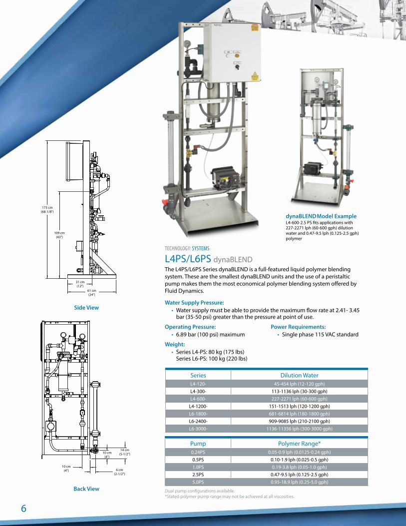
TECHNOLOGY: SYSTEMS
L4PS/L6PS dynaBLENDThe L4PS/L6PS Series dynaBLEND is a full-featured liquid polymer blending system. These are the smallest dynaBLEND units and the use of a peristaltic pump makes them the most economical polymer blending system offered by Fluid Dynamics.
Water Supply Pressure:• Water supply must be able to provide the maximum flow rate at 2.41- 3.45
bar (35-50 psi) greater than the pressure at point of use.
Operating Pressure:• 6.89 bar (100 psi) maximum
Weight:• Series L4-PS: 80 kg (175 lbs)
Series L6-PS: 100 kg (220 lbs)
Power Requirements:• Single phase 115 VAC standard
Side View
Back View
Series Dilution WaterL4-120- 45-454 lph (12-120 gph)L4-300- 113-1136 lph (30-300 gph)L4-600- 227-2271 lph (60-600 gph)
L4-1200- 151-1513 lph (120-1200 gph)L6-1800- 681-6814 lph (180-1800 gph)L6-2400- 909-9085 lph (210-2100 gph)L6-3000- 1136-11356 lph (300-3000 gph)
Pump Polymer Range*0.24PS 0.05-0.9 lph (0.0125-0.24 gph)0.5PS 0.10-1.9 lph (0.025-0.5 gph)1.0PS 0.19-3.8 lph (0.05-1.0 gph)2.5PS 0.47-9.5 lph (0.125-2.5 gph)5.0PS 0.95-18.9 lph (0.25-5.0 gph)
Dual pump configurations available.*Stated polymer pump range may not be achieved at all viscosities.
dynaBLEND Model Example
L4-600-2.5 PS fits applications with 227-2271 lph (60-600 gph) dilution water and 0.47-9.5 lph (0.125-2.5 gph) polymer

173 cm(68-1/8")
113 cm(44-1/2")
31 cm(12")
61 cm(24")
14 cm(5-1/2")
6 cm(2-1/2")
10 cm(4")
17 cm(6-1/2")
173 cm(68-1/8")
113 cm(44-1/2")
31 cm(12")
61 cm(24")
14 cm(5-1/2")
6 cm(2-1/2")
10 cm(4")
17 cm(6-1/2")
7
TECHNOLOGY: SYSTEMS
L4-P/L6-P dynaBLENDThe L4-P/L6-P Series dynaBLEND offers the same flow rates and features of the L4-PS/L6-PS Series with an upgrade to a progressing cavity pump. The progressing cavity pump provides increased life cycle.
Water Supply Pressure:• Water supply must be able to provide the maximum flow rate at 2.41- 3.45
bar (35-50 psi) greater than the pressure at point of use.
Operating Pressure:• 6.89 bar (100 psi)
Weight:• Series L4-P: 114 kg (250 lbs)
Series L6-P: 125 kg (275 lbs)
Power Requirements:• Single phase 115 VAC standard
Series Dilution WaterL4-120- 45-454 lph (12-120 gph)L4-300- 113-1136 lph (30-300 gph)L4-600- 227-2271 lph (60- 600 gph)
L4-1200- 454-4543 lph (120-1200 gph)L6-1800- 681-6814 lph (180-1800 gph)L6-2400- 909-9085 lph (210-2100 gph)L6-3000- 1136-11356 lph (300-3000 gph)
Pump Polymer Range1.2P 0.45-4.5 lph (0.12-1.2 gph)3.0P 1.13-11.3 lph (0.3-3.0 gph)6.0P 2.27-22.7 lph (0.6-6.0 gph)10P 3.8-37.9 lph (1.0-10.0 gph)15P 5.68-56.8 lph (1.5-15.0 gph)20P 7.57-75.7 lph (2.0-20.0 gph)
Dual pump configurations available.
dynaBLEND Model Example
L6-1800-6.0P fits applications with 681-6814 lph (180-1800 gph) dilution water and 2.3-22.7 lph (0.6-6.0 gph) polymer
Side View
Back View

8
TECHNOLOGY: SYSTEMS
L8-P/L12-P dynaBLENDThe L8-P/L12-P Series dynaBLEND include all features available throughout the line but in larger capacities.
L8-P/L12-P dynaBLENDs are designed to provide the highest standard water and polymer flow rates available on the market.
Water Supply Pressure:• Water supply must be able to provide the maximum flow rate at 2.41-3.45 bar
(35-50 psi) greater than the pressure at point of use.
Operating Pressure:• 6.89 bar maximum (100 psi)
Weight:• Series L8-P: 238 kg (525 lbs)
Series L12-P: 273 kg (600 lbs)
Power Requirements:• Single phase 115 VAC standard
Side View
Back View
Series Dilution WaterL8-3600- 1363-13627 lph (360-3600 gph)L8-4800- 1817-18170 lph (480-4800 gph)L8-6000- 2271-22712 lph (600-6000 gph)
L12-9000- 3407-34069 lph (900-9000 gph)L12-12000- 4543-45425 lph (1200-12000 gph)L12-21000- 7949-79494 lph (2100-21000 gph)
Pump Polymer Range15P 5.7-57.0 lph (1.5-15 gph)20P 7.6-76.0 lph (2.0-20 gph))25P 9.5-95.0 lph (2.5-25 gph)35P 13.3-133.0 lph (3.5-35 gph)50P 18.9-189.0 lph (5.0-50.0 gph)75P 28.4-284.0 lph (7.5-75 gph)
110P 41.6-416.0 lph (11-110 gph)150P 56.8-567.8 lph (15-150 gph)300P 113.5-1135.0 lph (30-300 gph)
Dual pump configurations available.
dynaBLEND Model Example
L8-6000-75P fits applications with 2271-22712 lph (600-6000 gph) dilution water and 28-284 lph (7.5-75 gph) polymer96 cm
(37-3/4")
46 cm(18-1/4") 91 cm
(36")
11 cm(4-1/4")
28 cm(11") 11 cm
(4-1/4")6 cm
(2-1/2")
15 cm(5-3/4")
17 cm(6-1/2")
96 cm(37-3/4")
46 cm(18-1/4") 91 cm
(36")
11 cm(4-1/4")
28 cm(11") 11 cm
(4-1/4")6 cm
(2-1/2")
15 cm(5-3/4")
17 cm(6-1/2")

9
Pump ControlPeristaltic Pumps can be furnished with manual or automatic speed control. Automatic control models accept a 4-20 mADC pacing signal which varies the speed of the pump. Pacing feature is available on all control levels except Control Level 1.
Progressing Cavity Pumps are offered in manual or auto-matic models. Automatic models accept a 4-20 mADC pacing signal, which varies the speed of the pump. Pump speed is interpolated as an indication of polymer flow where budget-ary constraints do not allow more sophisticated polymer flow measurement. Pacing feature is available on all control levels except Control Level 1.
Water MeasurementDifferential Pressure Switch—A non-quantitative device used to sense the loss of water flow. Alarm and system shut-down is provided on loss of water flow. This feature is standard on Control Level 3 and optional on Control Levels 4, 5 and 6.
Rotometer—A quantitative device which allows water flow rate to be observed locally. Standard on all units unless a higher level control is selected.
Turbine Flow Meter—A quantitative device which measures water flow and provides a signal to indicate the water flow rate. This signal is used to display the flow rate and/or as a part of the ratio control feature. This feature is standard for Control Levels 4, 5 and 6 and is optional on Control Level 3.
Magnetic Flow Meter—An alternative to the Turbine Flow Meter available to meet customer preferences. This feature is optional and available only on Control Levels 4, 5 and 6.
Polymer MeasurementCalibration Column—A pump draw-down cylinder is standard on all systems.
Thermal Flow Sensor—A non-quantitative device used to sense loss of polymer flow. Alarm and shutdown is provided when loss of polymer flow is sensed. This feature is optional on Control Levels 3, 4 and 5 and standard on Control Level 6.
Mass Flow Meter—A quantitative device which is a highly-sensitive instrument used to measure the flow of non-conductive and viscous liquids such as polymer, accurately, even at very low flows. The device provides a signal proportional to flow which may be used to display polymer flow rate and/or as the basis of the dynaBLEND ratio control feature with the highest accuracy. This option is available only on Control Levels 4, 5 and 6. When this option is selected, the thermal flow sensor is not required.
Auto FlushAutomatically initiated flush cycle. Cycle time is adjustable. Standard on Control Levels 4, 5 and 6; optional on Control Level 3.
Dry Polmer Preparation Units Available from Fluid Dynamics – request the dynaJET™ brochure.
Take ControlBecause controls are an integral part of every dynaBLEND system, Fluid Dynamics has developed the widest range of standard control panels available. Beginning with a simple discrete controller, through microprocessor-based controllers, all the way up to versatile PLC-based systems with touch screen interfaces and a variety of communication options, there is likely to be a pre-engineered system to meet your needs. If additional features are required, Fluid Dynamics’ electrical and software engineers, along with the UL panel shop will develop a custom solution for your application.
Control and Instrument OptionsControl Panel Options are shown on pages 10 and 11. Some of the available features include or allow the selection of accessories or options. These options are described below.
10
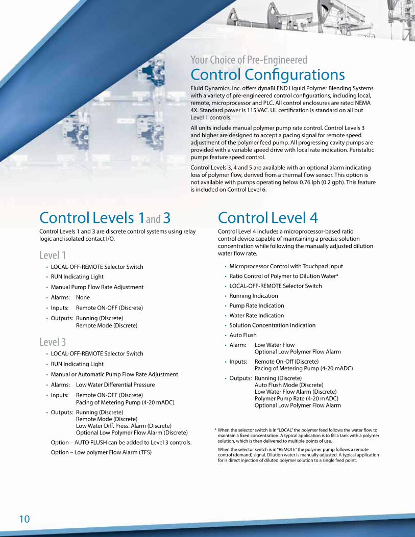
Control Levels 1and 3Control Levels 1 and 3 are discrete control systems using relay logic and isolated contact I/O.
Level 1• LOCAL-OFF-REMOTE Selector Switch
• RUN Indicating Light
• Manual Pump Flow Rate Adjustment
• Alarms: None
• Inputs: Remote ON-OFF (Discrete)
• Outputs: Running (Discrete) Remote Mode (Discrete)
Level 3• LOCAL-OFF-REMOTE Selector Switch
• RUN Indicating Light
• Manual or Automatic Pump Flow Rate Adjustment
• Alarms: Low Water Differential Pressure
• Inputs: Remote ON-OFF (Discrete) Pacing of Metering Pump (4-20 mADC)
• Outputs: Running (Discrete) Remote Mode (Discrete) Low Water Diff. Press. Alarm (Discrete) Optional Low Polymer Flow Alarm (Discrete)
Option – AUTO FLUSH can be added to Level 3 controls.
Option – Low polymer Flow Alarm (TFS)
Control Level 4Control Level 4 includes a microprocessor-based ratio control device capable of maintaining a precise solution concentration while following the manually adjusted dilution water flow rate.
• Microprocessor Control with Touchpad Input
• Ratio Control of Polymer to Dilution Water*
• LOCAL-OFF-REMOTE Selector Switch
• Running Indication
• Pump Rate Indication
• Water Rate Indication
• Solution Concentration Indication
• Auto Flush
• Alarm: Low Water Flow Optional Low Polymer Flow Alarm
• Inputs: Remote On-Off (Discrete) Pacing of Metering Pump (4-20 mADC)
• Outputs: Running (Discrete) Auto Flush Mode (Discrete) Low Water Flow Alarm (Discrete) Polymer Pump Rate (4-20 mADC) Optional Low Polymer Flow Alarm
Your Choice of Pre-EngineeredControl ConfigurationsFluid Dynamics, Inc. offers dynaBLEND Liquid Polymer Blending Systems with a variety of pre-engineered control configurations, including local, remote, microprocessor and PLC. All control enclosures are rated NEMA 4X. Standard power is 115 VAC. UL certification is standard on all but Level 1 controls.
All units include manual polymer pump rate control. Control Levels 3 and higher are designed to accept a pacing signal for remote speed adjustment of the polymer feed pump. All progressing cavity pumps are provided with a variable speed drive with local rate indication. Peristaltic pumps feature speed control.
Control Levels 3, 4 and 5 are available with an optional alarm indicating loss of polymer flow, derived from a thermal flow sensor. This option is not available with pumps operating below 0.76 lph (0.2 gph). This feature is included on Control Level 6.
* When the selector switch is in “LOCAL” the polymer feed follows the water flow to maintain a fixed concentration. A typical application is to fill a tank with a polymer solution, which is then delivered to multiple points of use.
When the selector switch is in “REMOTE” the polymer pump follows a remote control (demand) signal. Dilution water is manually adjusted. A typical application for is direct injection of diluted polymer solution to a single feed point.

11
Control Level 5Control Level 5 includes a microprocessor-based ratio control package to maintain a precise polymer solution concentra-tion. The device is configurable, through a local touchpad, to allow either water or polymer to follow a 4-20 mADC pacing signal. The non-paced flow is controlled automatically to maintain the desired solution concentration. Polymer solution concentration may be adjusted locally or by a second remote 4-20 mADC signal. When operating in a fully automatic mode, water flow is controlled automatically through the use of an integral linear actuated variable orifice (LAVO).
• Microprocessor Control with Touchpad Input
• Ratio Control of Polymer Solution Concentration
• Local Input Through Touchpad
• In Response to a Remote Signal
• LOCAL-OFF-REMOTE Selector Switch
• Running Indication
• Pump Rate Indication
• Water Rate Indication
• Solution Concentration Indication
• Auto Flush
• Alarms: Low Water Flow Solution Concentration FAULT 2
Optional Low Polymer Flow Alarm
• Inputs: Pacing Signal (4-20 mADC) 1
Solution Concentration (4-20 mADC) 1, 3
Remote On-Off (Discrete)
• Outputs: Running (Discrete) Remote Mode (Discrete) Auto Flush Mode (Discrete) Common Alarm (Discrete) Polymer Pump Rate (4-20 mADC)
Control Level 6Control Level 6 incorporates a PLC with a touch screen inter-face to maintain precise control of polymer solution concen-tration and flow rate. The system is configurable, through the integral touch screen, to select either water or polymer to follow a 4-20 mADC pacing signal. The non-paced flow is controlled automatically to maintain the desired solution concentration. Polymer solution concentration may be adjusted locally or by a second remote 4-20 mADC signal. When operating in a fully automatic mode, water flow is controlled automatically through the use of an integral linear actuated variable orifice (LAVO).
• PLC Control with Touch Screen Interface
• Ratio Control of Polymer Solution Concentration
• Local Input Through Touch Screen
• In Response to a Remote Signal
• LOCAL-OFF-REMOTE Selection (Touch Screen)
• Running Indication
• Pump Rate Indication
• Water Rate Indication
• Solution Concentration Indication
• Auto Flush
• Alarms: Low Water Flow (Adjustable Set Point) No Polymer Flow (Thermal Flow Sensor) Solution Concentration FAULT 2
Optional Low Polymer Flow Alarm
• Inputs: Pacing Signal (4-20 mADC) 1
Solution Concentration (4-20 mADC) 1, 3
Remote On-Off (Discrete)
• Outputs: Running (Discrete) Remote Mode (Discrete) Auto Flush Mode (Discrete) Common Alarm (Discrete) Solution Flow Rate (4-20 mADC) Polymer Pump Rate (4-20 mADC) Dilution Water Flow Rate (4-20 mADC)
1 The primary 4-20 mADC pacing signal can drive either water or polymer flow rate as master. A second 4-20 mADC signal is used to adjust the solution concentration.
2 A solution concentration FAULT is an indication of insufficient dilution water to satisfy concentration requirement.3 This input is separate from the pacing signal.

A u t h o r i z e d P S G P a r t n e r :
Printed in the U.S.A. Copyright 2013 ©Pump Solutions Group (PSG), A Dover Company FLD-11000-C-01
PSG reserves the right to modify the information and illustrations contained in this document without prior notice. This is a non-contractual document. 06-2013
Where Innovation Flows
klosee
Stamp
klosee
Stamp
klosee
Stamp
Related Documents