www.conairgroup.com Corporate Office: 724.584.5500 l Instant Access 24/7 (Parts and Service): 800.458.1960 l Parts and Service: 814.437.6861 USER GUIDE UGE026- 0596b CAT-A-CUTTER

Welcome message from author
This document is posted to help you gain knowledge. Please leave a comment to let me know what you think about it! Share it to your friends and learn new things together.
Transcript
www.conairgroup.com
Corporate Office: 724.584.5500 l Instant Access 24/7 (Parts and Service): 800.458.1960 l Parts and Service: 814.437.6861
U S E R G U I D E
UGE026-0596b
CAT-A-CUTTER Instructions
"GATTO MACHINERY DEVELOPMENT CORP.
SECTION 1
1.1 1.2 1 . 2 .1 1. 2. 21 . 2. 3
SECTION 2
2 .1 2.2 2.3
SECTION 3
3 .1 3.2 3.3 3.4
SECTION 4
TABLE OF CONTENTS
- GENERAL SPECIFICATIONS
- Technical Data- Operation and Installation- Operation- Placement in Line- Electrical Supply
- MECHANICAL SYSTEM
- Knife Assembly- Shearing Anvil- Single Revolution Clutch
- ELECTRICAL SYSTEM
- Schematic Drawing- Drive Motor Specifications- Cut-Length Programmer- Control Box
- SET UP
4.1 - Set Up4.2 - Operation4.3 - Automatic (Encoder) Operation4.4 - Product Counter4. 5 - Remote Operation4. 6 - Safety
SECTION 5
5.1 5.2 5.3 5.4 5.5 5.6 5.7 5.8
SECTION 6
6. 16.2
- SERVICING AND MAINTENANCE
- Changing Knife Blades- Lubrication- Timing Belt- Trouble Shooting - Mechanical- Trouble Shooting - Electrical- Encoder Testing- Operation at other Voltage- Clutch Operation and Servicing
INDEX
- Spare Parts- Drawings

GATTO MACHINERY DEVELOPMENT CORP.
SECTION 1
GENERAL SPECIFICATIONS
GATTO MACHINERY DEVELOPMENT CORP.
SECTION l
l. l
- GENERAL SPECIFICATIONS
Technical Data
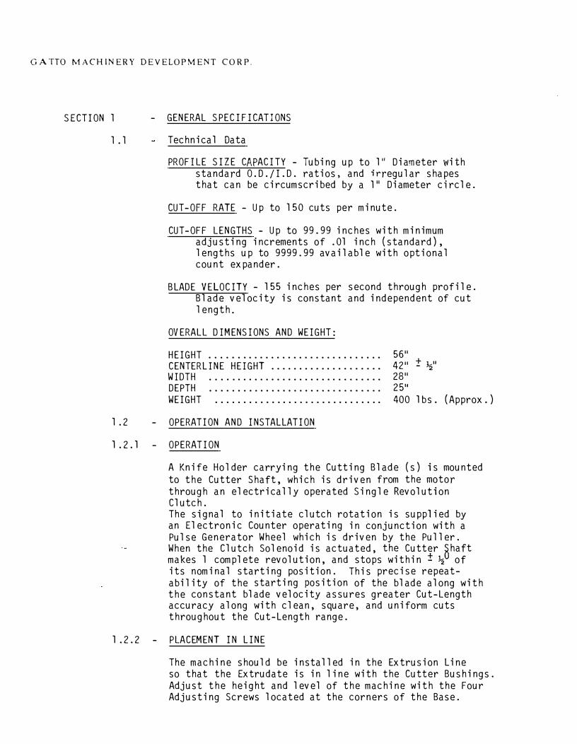
PROFILE SIZE CAPACITY - Tubing up to l" Diameter withstandard O.D./I.D. ratios, and irregular shapes that can be circumscribed by a 111 Diameter circle.
CUT-OFF RATE - Up to 150 cuts per minute.
CUT-OFF LENGTHS - Up to 99.99 inches with minimum adjusting increments of .01 inch (standard), lengths up to 9999.99 available with optional count expander.
BLADE VELOCITY - 155 inches per second through profile. Blade velocity is constant and independent of cut length.
OVERALL DIMENSIONS AND WEIGHT:
HEIGHT .............................. . CENTERLINE HEIGHT ................... . WIDTH .............................. . DEPTH .............................. . WEIGHT ............................. .
56 11
4211 + 1 II
- '2
2811
25 11
400 1 bs. (Approx.)
l .2 - OPERATION AND INSTALLATION
1.2.1 - OPERATION
A Knife Holder carrying the Cutting Blade (s) is mounted to the Cutter Shaft, which is driven from the motor through an electrically operated Single Revolution Clutch. The signal to initiate clutch rotation is supplied by an Electronic Counter operating in conjunction with a Pulse Generator Wheel which is driven by the Puller. When the Clutch Solenoid is actuated, the Cutter nhaft makes 1 complete revolution, and stops within±½ of its nominal starting position. This precise repeatability of the starting position of the blade along with the constant blade velocity assures greater Cut-Length accuracy along with clean, square, and uniform cuts throughout the Cut-Length range.
1 .2.2 - PLACEMENT IN LINE
The machine should be installed in the Extrusion Line so that the Extrudate is in line with the Cutter Bushings. Adjust the height and level of the machine with the Four Adjusting Screws located at the corners of the Base.
· GATTO MACHINERY DEVELOPMENT CORP.
1. 2 .3 ELECTRICAL SUPPLY
A.C. A Three-Phase, Four Wire Power Cord with Polarized Twist-Lock Plug for connection to Plant Power is furnished, connected to the machine. Make certain that the Plant Supply Voltage corresponds to the Voltage stamped on the specification plate located at the front of the machine. The Polarized Prong of the plug should be connected to the Plant Ground. The Electrical Power Source should be fused in accordance with applicable Electrical Codes. CHECK TO ASSURE THAT DIRECTION OF MOTOR ROTATION IS CORRECT.
NOTE: The electrical noise generated by the extruder or other auxilliary equipment could cause the cutter to cycle unintentionally. To avoid this, do not operate the cutter from the same supply line used to supply power to the extruder or any other equipment which could generate electrical noise in the power mains.

GATTO MACHINERY DEVELOPMENT CORP.
SECTION 2
MECHANICAL SYSTEM
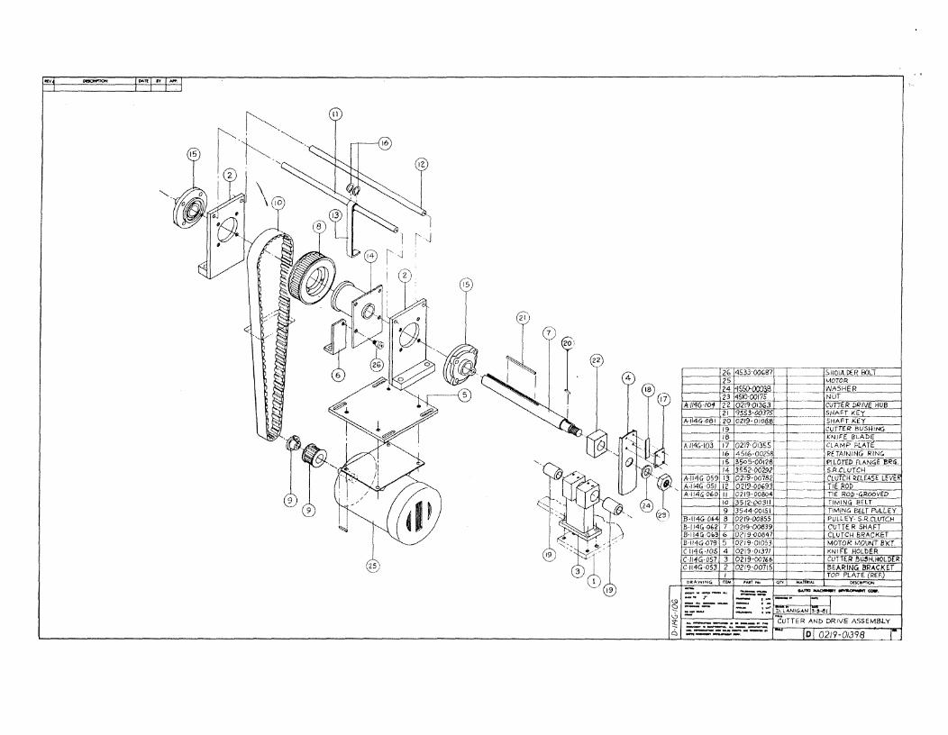
(S DWG. NO. D-114G-106)
GATTO MACHINERY DEVELOPMENT CORP.
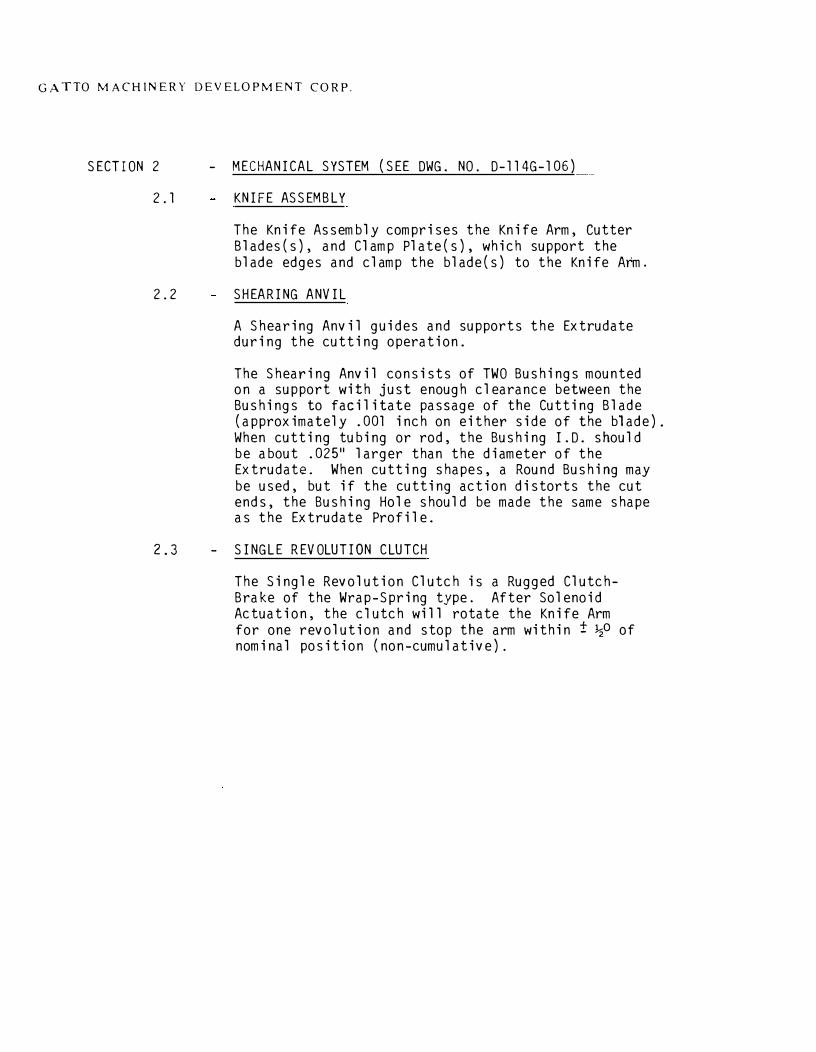
SECTION 2 - MECHANICAL SYSTEM (SEE DWG. NO. D-114G-106)
2.1 KNIFE ASSEMBLY
The Knife Assembly comprises the Knife Arm, CutterBlades(s), and Clamp Plate(s), which support theblade edges and clamp the blade(s) to the Knife Arm.
2.2 SHEARING ANVIL
2.3
A Shearing Anvil guides and supports the Extrudateduring the cutting operation.
The Shearing Anvil consists of TWO Bushings mountedon a support with just enough clearance between theBushings to facilitate passage of the Cutting Blade(approximately .001 inch on either side of the blade).When cutting tubing or rod, the Bushing I.D. shouldbe about .025 11 larger than the diameter of theExtrudate. When cutting shapes, a Round Bushing maybe used, but if the cutting action distorts the cutends, the Bushing Hole should be made the same shapeas the Extrudate Profile.
- SINGLE REVOLUTION CLUTCH
The Single Revolution Clutch is a Rugged ClutchBrake of the Wrap-Spring type. After SolenoidActuation, the clutch will rotate the Knife Armfor one revolution and stop the arm within± ½0 ofnominal position (non-cumulative).

GATTO MACHINERY DEVELOPMENT CORP.
SECTION 3
ELECTRICAL SYSTEM
GATTO MACHINERY DEVELOPMENT CORP.
SECTION 3
3. 1
ELECTRICAL SYSTEM
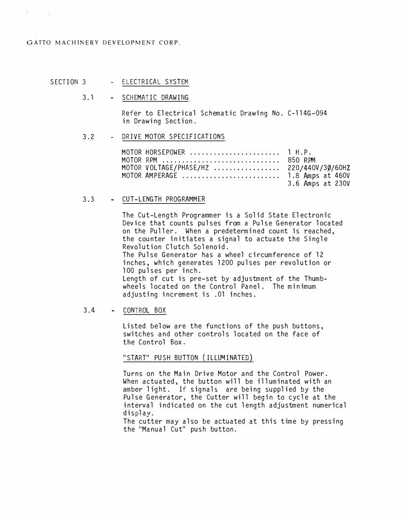
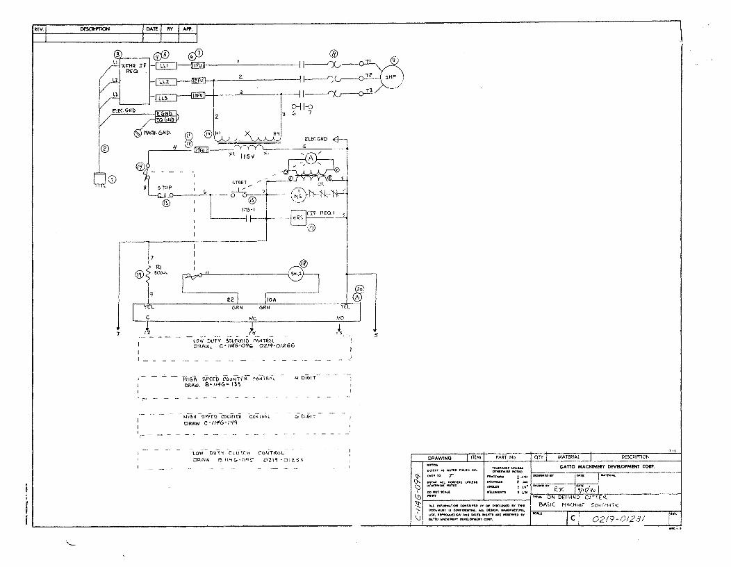
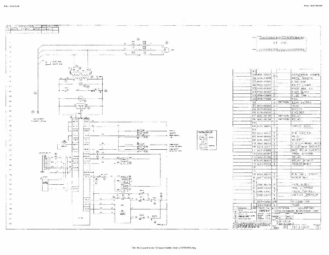
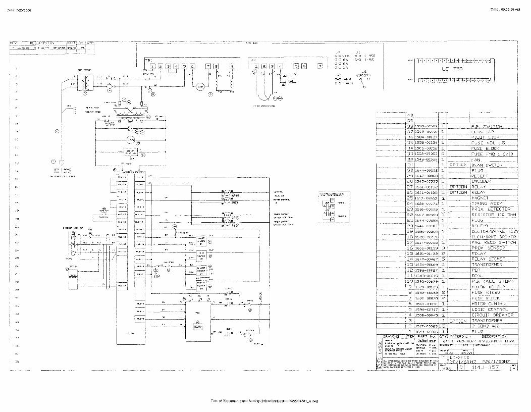
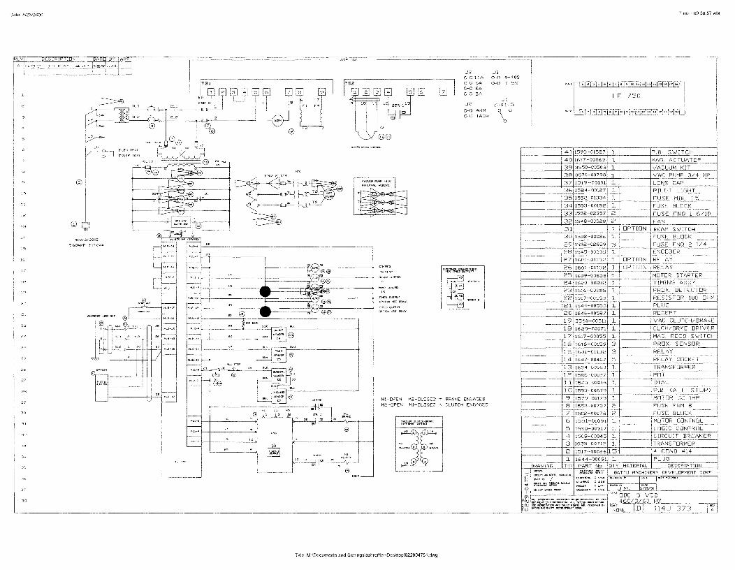
- SCHEMATIC DRAWING
Refer to Electrical Schematic Drawing No. C-114G-094in Drawing Section.
3.2 DRIVE MOTOR SPECIFICATIONS
MOTOR HORSEPOWER ...................... . MOTOR RPM ............................. . MOTOR VOLTAGE/PHASE/HZ ................ . MOTOR AMPERAGE ........................ .
3.3 CUT-LENGTH PROGRAMMER
1 H.P. 850 RPM
220/440V/3�/60HZ 1 .8 Amps at 460V 3.6 Amps at 230V
The Cut-Length Programmer is a Solid State Electronic Device that counts pulses from a Pulse Generator located on the Puller. When a predetermined count is reached, the counter initiates a signal to actuate the Single Revolution Clutch Solenoid. The Pulse Generator has a wheel circumference of 12 inches, which generates 1200 pulses per revolution or 100 pulses per inch. Length of cut is pre-set by adjustment of the Thumbwheels located on the Control Panel. The minimum adjusting increment is .01 inches.
3.4 CONTROL BOX
Listed below are the functions of the push buttons, switches and other controls located on the face of the Control Box.
11START11 PUSH BUTTON (ILLU�INATED)
Turns on the Main Drive Motor and the Control Power. When actuated, the button will be illuminated with an amber light. If signals are being supplied by the Pulse Generator, the Cutter will begin to cycle at the interval indicated on the cut length adjustment numerical display. The cutter may also be actuated at this time by pressing the 1
1 Manual Cut" push button.
vGATTO MACHINERY DEVELOPMENT CORP.
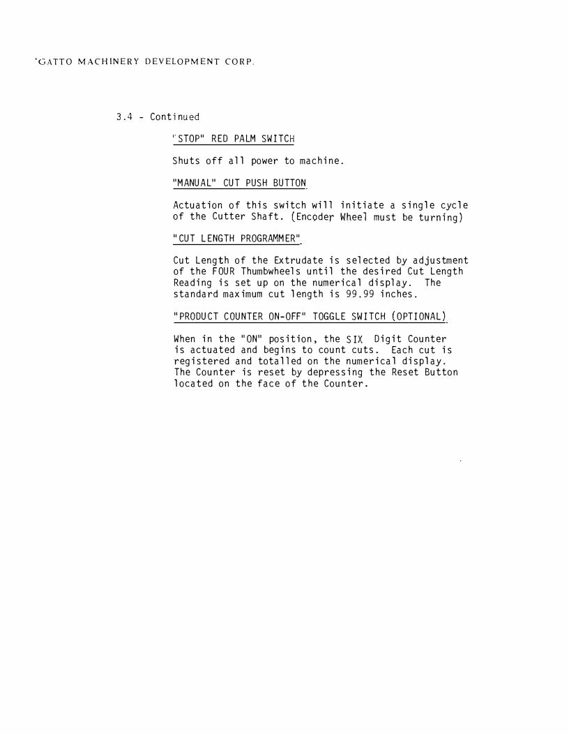
3.4 - Continued
I' STOP" RED PALM SWITCH
Shuts off all power to machine.
"MANUAL" CUT PUSH BUTTON
Actuation of this switch will initiate a single cycle of the Cutter Shaft. (Encoder Wheel must be turning)
11 CUT LENGTH PROGRAMMER"
Cut Length of the Extrudate is selected by adjustment of the FOUR Thumbwheels until the desired Cut Length Reading is set up on the numerical display. The standard maximum cut length is 99.99 inches.
11 PRODUCT COUNTER ON-OFF" TOGGLE SWITCH ( OPTIONAL)
When in the "ON" position, the SIX Digit Counter is actuated and begins to count cuts. Each cut is registered and totalled on the numerical display. The Counter is reset by depressing the Reset Button located on the face of the Counter.

GATTv MACHINERY DEVELOPMENT CORP.
SECTION 4
4. l
4.2
4.3
SET UP
SET UP (DO NOT PLUG IN ELECTRIC LINE}
Set the Cutter in the Extrusion Line as explained in Section 1.2.2.
OPERATION (Drawinq #0219-01398)
Open the hinged cover and make sure that the cutting blade is passing cleanly between the TWO Cutter Bushings by rotating the Knife Holder by hand. It will be necessary to release the Clutch to rotate the blade. To release the Clutch, push in on the Clutch Release Lever (item 13 on Drawing.). This will allow the Clutch to be rotated by hand for one revolution.
AUTOMATIC (ENCODER) OPERATION
Connect the cable from the Encoder to the Encoder Input Jack, located at the rear of the cutter. Caution, DO NOT connect or disconnect the Encoder with the power on. Set the cut programmer Thumb Wheel Switch to 99.99. After checking to see if all guards are closed, plug the line cord into a source of power. lCheck machine identification plate) Depress the Start Push Button. The yellow light, part of the Start Push Button, should light and the 1 H.P. Motor should run. If the Encoder Assembly is being driven by the Puller, start the puller. If not, rotate the Encoder Wheel by hand until the cutter actuates. (Approx. 9 rev.) The Encoder Wheel measures 12 inches circumference. When the wheel rotates 1 complete revolution, the encoder will generate 1200 pulses. Therefore, the 12 inch wheel is divided by 1200. So, each pulse will be equal to .01 inch of wheel travel. To cut a length 10.01 inches set the thumb wheel switch to 10.01.

GATTO MACHINERY DEVELOPMENT CORP.
SECTION 4
SET-UP
GATTO MACHINERY DEVELOPMENT CORP.
SECTION 5
5. l
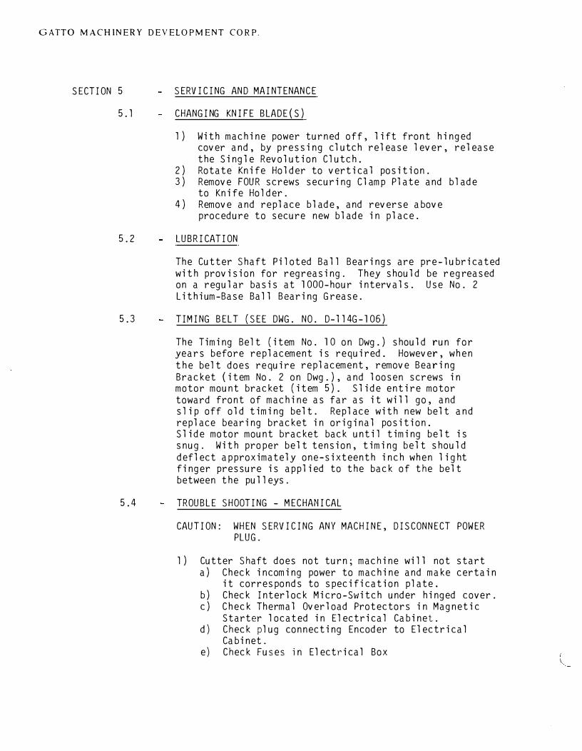
SERVICING AND MAINTENANCE
CHANGING KNIFE BLADE(S)
l) With machine power turned off, lift front hingedcover and, by pressing clutch release lever, releasethe Single Revolution Clutch.
2) Rotate Knife Holder to vertical position.3) Remove FOUR screws securing Clamp Plate and blade
to Knife Hold er.4) Remove and replace blade, and reverse above
procedure to secure new blade in place.
5.2 LUBRICATION
The Cutter Shaft Piloted Ball Bearings are pre-lubricated with provision for regreasing. They should be regreased on a regular basis at 1000-hour intervals. Use No. 2 Lithium-Base Ball Bearing Grease.
5.3 TIMING BELT (SEE DWG. NO. D-ll4G-106)
The Timing Belt (item No. 10 on Dwg.) should run for years before replacement is required. However, when the belt does require replacement, remove Bearing Bracket (item No. 2 on Dwg.), and loosen screws in motor mount bracket (item 5). Slide entire motor toward front of machine as far as it will go, and slip off old timing belt. Replace with new belt and replace bearing bracket in original position. Slide motor mount bracket back until timing belt is snug. With proper belt tension, timing belt should deflect approximately one-sixteenth inch when light finger pressure is applied to the back of the belt between the pulleys.
5.4 TROUBLE SHOOTING - MECHANICAL
CAUTION: WHEN SERVICING ANY MACHINE, DISCONNECT POWER PLUG.
l) Cutter Shaft does not turn; machine will not starta) Check incoming power to machine and make certain
it corresponds to specification plate.b) Check Interlock Micro-Switch under hinged cover.c) Check Thermal Overload Protectors in Magnetic
Starter located in Electrical Cabinet.d) Check plug connecting Encoder to Electrical
Cabinet.e) Check Fuses in Electrical Box

GATTO MACHINERY DEVELOPMENT CORP.
SECTION 5
SERVICING AND MAINTENANCE
GATTO MACHINERY DEVELOPMENT CORP.
4. 5 - Continued
CAUTIONS: Remove power to machine before making any wiring changes.
NOTE: After installation, the operator will observe that the cutter will initiate one cut cycle for each actuation of the Limit Switch or Relay contacts. The contacts must close, then open, then close again to initiate a new cut cycle.
4. 6 SAFETY
As with all GATTO equipment, safety is designed into the machine and not added on as an afterthought. The machine is completely safety-enclosed and yet the efficiency and accessability are not impaired. All of the operating controls are carefully clustered at eye level for safety and convenience. For added safety, a Micro-Switch Interlock stops the motor if the front cover is opened while the machine is in operation. The Guards are "OSHA" color coded.
GATTO MACHINERY DEVELOPMENT CORP.
4. 3 - Continued
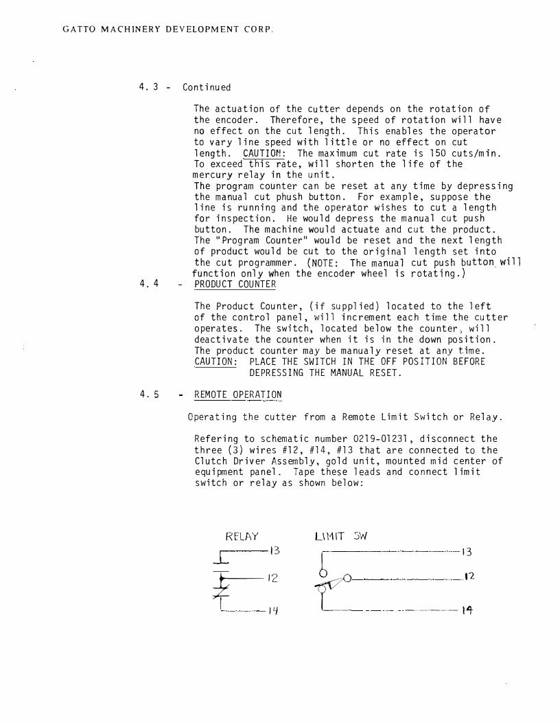
The actuation of the cutter depends on the rotation of the encoder. Therefore, the speed of rotation will have no effect on the cut length. This enables the operator to vary line speed with little or no effect on cut length. CAUTION: The maximum cut rate is 150 cuts/min. To exceed this rate, will shorten the life of the mercury relay in the unit. The program counter can be reset at any time by depressing the manual cut phush button. For example, suppose the line is running and the operator wishes to cut a length for inspection. He would depress the manual cut push button. The machine would actuate and cut the product. The II Program Counter" would be reset and the next length of product would be cut to the original length set into the cut programmer. (NOTE: The manual cut push button. will function only when the encoder wheel is rotating.)
4. 4 PRODUCT COUNTER
The Product Counter, (if supplied) located to the left of the control panel, will increment each time the cutter operates. The switch, located below the counter, will deactivate the counter when it is in the down position. The product counter may be manualy reset at any time. CAUTION: PLACE THE SWITCH IN THE OFF POSITION BEFORE
DEPRESSING THE MANUAL RESET.
4. 5 REMOTE OPERATION
Operating the cutter from a Remote Limit Switch or Relay.
Refering to schematic number 0219-01231, disconnect the three (3) wires #12, #14, #13 that are connected to the Clutch Driver Assembly, gold unit, mounted mid center of equipment panel. Tape these leads and connect limit switch or relay as shown below:
RfLAY
L 13
r-12
I 14
L\MIT SW
13
b 12
t:: -----··--·-- I�
)
GATTO MACHINERY DEVELOPMENT CORP.
5.4 Continued
2) Motor starts but Knife Holder does not cycle.
a) Check Timing Belt. b) Check for broken Shaft or Key. c) Check to insure that Clutch Solenoid is being
energized. d) Check that pawl of clutch is being pulled
clear of step on stop collar by solenoid. Check to insure that the pawl pivots freely. To do this apply finger pressure against the pawl in the area of the Solenoid Plunger. The pawl should move against the spring with very light pressure. If it does not, the Solenoid should be removed, Two 10-32 Allen Cap Screws retain the Solenoid. Then remove Paul which is retained by a Snap Ring.
3) Clutch builds up excessive heat.
The clutch will build up heat in normal operation and, as with an electric motor, this temperture rise is not detrimental. To detect excessive heat, feel the rectangular clutch plate upon which the solenoid is mounted. It should be warm, but not so hot that you can not keep your finger on it. If this is the case, proceed as follows:
a)
b)
Check Timing Belt tension. Adjust if too tight. Check to insure that the clutch plate is free to 11 Float11 (approximately± 1° radially a-:d ± 1/32 11 axially}. This 11 Float 11 is controlled by the bracket and shoulder screw (items No. 6 a~d 27 on Dwg. No. D-114G-106).
4) Clutch does not rotate freely when turning by hand with pawl disengaged.
If checks 11 A11 and "B" above do not alleviate problem, call GATTO Service Department.
GATTO MACHINERY DEVELOPMENT CORP.
5.5 TROUBLE SHOOTING - ELECTRICAL
Referring to schematic #C-114G-094, 115 volt power is connected to one end of Rl (500) when the machine is running. The other side of Rl (wire #9) connects to the yellow input terminal of the clutch driver assembly, gold unit, mounted mid center of equipment panel. The three (3) terminals marked C, NC, and NO, control the action of the clutch driver assembly. The assembly will output a 150 volt pulse whenever the "C" to "NC" connection is broken. At the same time, the "C" to 11N011
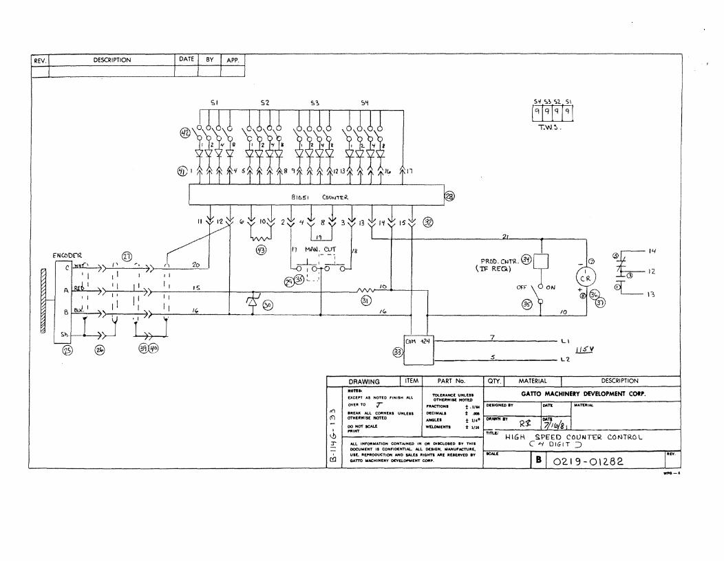
connection must be completed. Referring to schematic #B114G-133 , the relay contacts that perform this function are shown to the extreme right. Each time the relay ICR is energized, the contacts will change state and the clutch driver assembly will output a 150 volt pulse, 15 M Sec. long. This pulse will cause the clutch solenoid to pull in and allow the clutch to complete one cut cycle. Note that one end of the relay ICR is connected to the positive terminal of the 24V D.C. power supply. Therefore, all that is needed to cause a cut cycle is to connect the other end of the coil of ICR to common (wire #16). This is precisely the function of the cut programmer. At count-out pin #13, on the programmer, is connected to common for approx. 100 milli second.
The TWO led indicators at the right edge of the program counter are useful trouble shooting tools. The indicator, at the right, will light each time an encoder pulse is received by the counter. If a problem develops, where the machanic does not know if the encoder or program counter is at fault, the following may prove helpful:
1) Stop the cutter.2) Remove the jack which connects the encoder to
the cutter.3) Set the cut programmer to 0003.4} Connect a wire to wire #20.5) Start the cutter.6) While observing the led, on the right side of
the product counter, touch the wire to #16.The led should light each time the connectionis made. If the led does light, the encoderor wiring to the encoder is at fault. Aftertouching wire #16 three (3) times (we set theprogrammer to 0003) the led, on the left, shouldflash and the clutch should complete onerev o 1 u t ion .

GA-fTO MACHINERY DEVELOPMENT CORP.
5.5 #6 continued�
If the led, to the left, does flash, in response to the above test, the problem is with the mercury relay, located to the left of the equipment panel or with the clutch drive assembly, gold unit, mounted mid center of equipment panel. To test the clutch driver assembly, connect a limit switch as described on page 11 . If the clutch functions with the limit switch, the problem is with the relay. If not, the clutch driver assembly is at fault.
GAT'IO MACHINERY DEVELOPMENT CORP.
5.5 Continued
The TWO led indicators at the right edge of the counter printed circuit board are useful trouble shooting tools. The upper indicator will light each time an encoder pulse is received by the counter, If a problem develops, where the mechanic does not know if the encoder or program counter is at fault, the following may prove helpful:
l} Stop the cutter2) Remove the jack which connects the encoder to
the cutter.3} Set the cut programmer to 0003,4} Connect a wire to wire #20.5} Start the cutter.6) While observing the upper led touch the wire
to #16. The led should light each time theconnection is made. If the led does light,the encoder or wiring to the encoder is atfault. After touching wire, #16 three (3}times (we set the programmer to 0003} thelower led should flash and the clutch shouldcomplete one revolution.If the lower led does flash, in response tothe above test, the problem is with the mercuryrelay, located to the left of the equipllentpanel or with the clutch drive assembly, goldunit, mounted mid center of equipllent panel.To test the clutch driver assembly, connect alimit switch as described on Page 11.If the clutch functions with the limit switch,the problem is with the relay. If not, theclutch driver assembly is at fault.
GATTO MACHINERY DEVELOPMENT CORP.
5.6
5.7
ITEM 1 VOLTAGE PLUG
440 71630-NP
220 71530-NP
208 71530-NP
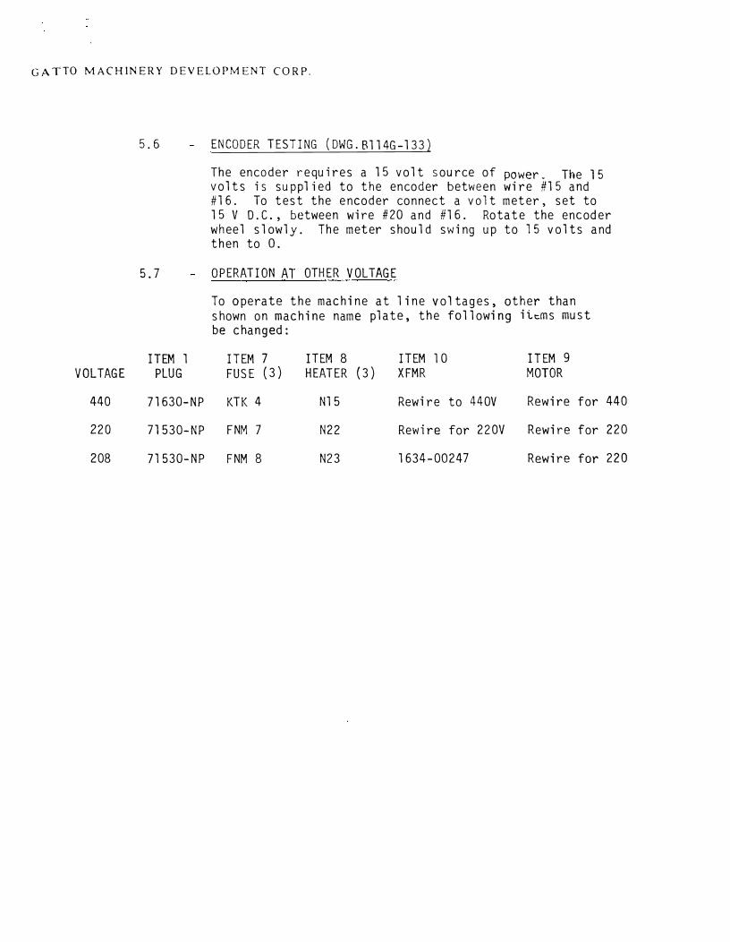
ENCODER TESTING (DWG.B1l4G-l33)
The encoder requires a 15 volt source of power. The 15 volts is supplied to the encoder between wire #15 and #16. To test the encoder connect a volt meter, set to 15 V D.C., between wire #20 and #16. Rotate the encoder wheel slowly. The meter should swing up to 15 volts and then to 0.
OPERATION AT OTHER VOLTAGE
To operate the machine at line voltages, other than shown on machine name plate, the following ii..t:.ms must be changed:
ITEM 7 ITEM 8 ITEM l 0 ITEM 9 FUSE (3) HEATER (3) XFMR MOTOR
KTK 4 Nl 5 Rewire to 440V Rewire for 440
FNM 7 N22 Rewire for 220V Rewire for 220
FNM 8 N23 1634-00247 Rewire for 220

GATl O MACHINERY DEVELOPMENT CORP.
SECTICN 5.8 CLUTCH OPERATION AND SERVICING
ODC-1 CLUTCH FUNCTION
Just as the spring clutch can be used to transmit rotation from an
input to a load by joining two hubs in a positive engagement, it can
also be used to brake the rotation of the load by joining a rotating
hub to a stationary hub in a positive engagement in the Spring Brake.
The control tang holds the spring open to permit rotation of the load.
�hen released, the spring wraps down on the output hub, braking the
1 oad.
PSI has developed and patented a method of combining the two functions
- clutching and braking - in a single wrap-spring rotation control
device, which can then be used to start and stop a load, always stopping
at the desired spot without cumulative error. In this device, the
brake spring is wrapped down to engage by the same collar that unwraps
the clutch spring. The essential difference in performance between the
Clutch-Brake and the Single-Revolution Clutch is that the former will
stop any load that it is able to start, whereas the latter will only
stop about 10% of the starting load.
)
GATTO MACHINERY DEVELOPMENT CORP.
SECTION 5.8 Continued
ODC -1 CLUTCH SERVICING
A) CLEANING: The Input Hub (Item #2), the Output Assembly (Item #6), and
the Brake Hub (Item #9) are an oil impregnated material and
SHOULD NOT be washed in any type harsh degreaser or gasoline.
Kerosene is recommended.
B) OILING: After cleaning the Input Hub, the Output Assembly, and the
Brake Hub, they must then be oiled. Bring oil solution to
a boil, remove from heat, and add parts to be oiled only
(Items #2, #6 and #9). Let parts sit for a\'1hile, oil will
impregnate itself into parts.
GATTO MACHINERY DEVELOPMENT CORP.
SECTION 5 .8
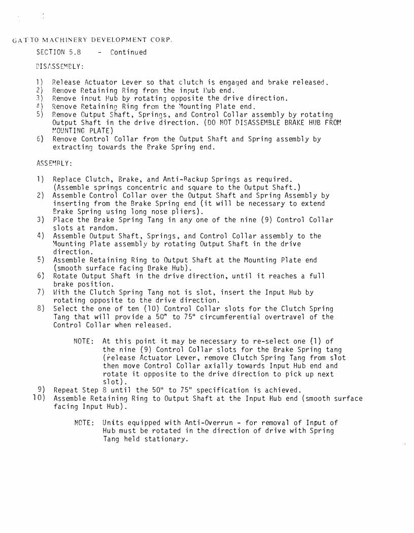
C'ISt,SSEM8L Y:
Continued
l) Release Actuator Lever so that clutch is engaged and brake released.2) Remove Retaining Ring from the in::iut t'.ub end.3) Remove input Hub by rotatin9 opposite the drive direction.l'.I) Rer.iove Retainin9 Ring from the :founting Plate end. 5) Remove Cutput Shaft, Springs, and Control Collar assembly by rotating
Output Shaft in the drive direction. (DO NOT DISASSEMBLE BRAKE HUB FROM�·ouNTING PLATE)
6) Remove Control Collar from the Output Shaft and Spring assembly byextracting towards the erake Spring end.
ASSP1RLY:
l )
2)
3}
4)
5)
6}
7)
8)
9} 10)
Replace Clutch, Brake, and Anti-8ackup Springs as required. (Assemble springs concentric and square to the Output Shaft.) Assemble Control Collar over the Output Shaft and Spring Assembly by inserting from the Brake Spring end (it will be necessary to extend Erake Spring using long nose pliers). Place the Brake Spring Tang in any one of the nine (9) Control Collar slots at random. Assemble Output Shaft, Springs, and Control Collar assembly to the �ounting Plate assembly by rotating Output Shaft in the drive direction. Assemble Retaining Ring to Output Shaft at the Mounting Plate end (smooth surface facing Brake Hub). Rotate Output Shaft in the drive direction, until it reaches a full brake position. v!ith the Clutch Spring Tang not is slot, insert the Input Hub by rotating opposite to the drive direction. Select the one of ten (10) Control Collar slots for the Clutch Spring Tang that will provide a 50" to 75" circumferential overtravel of the Control Collar when released.
NOTE: At this point it may be necessary to re-select one (1) of the nine (9) Control Collar slots for the Brake Spring tang (release Actuator Lever, remove Clutch Spring Tang from slot then move Control Collar axially towards Input Hub end and rotate it opposite to the drive direction to pick up next s 1 ot) .
Repeat Step 8 until the 50" to 75" specification is achieved. Assemble Retaining Ring to Output Shaft at the Input Hub end (smooth surface facing Input Hub).
MOTE: Units equipped with Anti-Overrun - for remova 1 of Input of Hub must be rotated in the direction of drive with Spring Tang held stationary.
GATTO MACHINERY DEVELOPMENT CORP.
SECTION 5.8 Continued
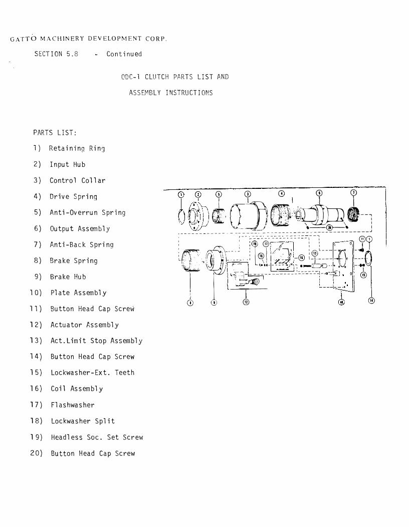
ODC-1 CLUTCH PARTS LIST AND
ASSEMBLY INSTRUCTIONS
PARTS LIST:
l) Retaining Ring
2) Input Hub
3) Control Collar
4) Drive Spring
5) Anti-Overrun Spring
6) Output Assembly
7) Anti-Back Spring
8) Brake Spring
9) Brake Hub
10) Plate Assembly
11) Button Head Cap Screw
12) Actuator Assembly
13) Act. Limit Stop Assembly
14) Button Head Cap Screw
15) Lockwasher-Ext. Teeth
16) Coil Assembly
17) Flashwasher
18) Lockwasher Split
l 9} Headless Soc. Set Screw
20) Button Head Cap Screw
© © 0 0 Q)
I ]I_·'·· l I
\ ff'. (T �.I
'.
m;:··:�:\· ... ;_ �. I •; .---,� f';, ,', I 11
I I'
� \ ' \ ---�-/ •--@--• I -- ---- ----- - ----- -- ----- --- ______________ J
, r-- --- -- - --- - --1
: ' : ;. -®· - -�- - - - -1 : 0 0 ®? �rr JTII�< l�1 �;;-® :t===-r1 =±(l
\�,' , �/ / I (' ,_-u-----.;, - ·-�o--:tl _...,.y-·�
I ._.;.. \ 0 0
I
(!) l h���--
- ____ Coc--_-_-"j_ o @ ®
GATTO MACHINERY DEVELOPMENT CORP.
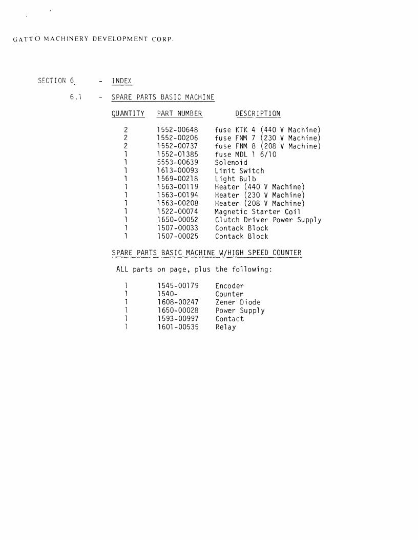
SE CTI ON 6
6. l
INDEX --
SPARE PARTS BASIC MACHINE
QUANTITY PART NUMBER D ESCR I PTI ON
2 1552-00648 fuse KTK 4 (440 V Machine) 2 1552-00206 fuse FNM 7 (230 V Machine) 2 1552-00737 fuse FNM 8 (208 V Machine) 1 1552-01385 fuse MDL 1 6/1 O 1 5553-00639 Solenoid 1 1613-00093 Limit Switch 1 1569-00218 Light Bulb 1 1563-00119 Heater (440 V Machine) 1 1563-00194 Heater (230 V Machine) 1 1563-00208 Heater (208 V Machine) 1 1522-00074 Magnetic Starter Coil 1 1650-00052 Clutch Driver Power Supply 1 1507-00033 Contack Block 1 1507-00025 Contack Block
SPARE PARTS BASIC MACHINE W/HIGH SPEED COUNTER
ALL parts on page, plus the following:
1 1 l 1 1 1
1545-00179 1540-1608-00247 1650-00028 1593-00997 1601-00535
Encoder Counter Zener Diode Power Supply Contact Relay
. I i
REV. DESOlll'TION
),1
Ll
XF"HR .n· l?.G
DATl: I BY I APP.
® I ® I~~
z,___ II -··0~)
(ifl) cefi) 1-ClIC]-illru----'---------<
~1:r:~ Lfil_j = 3 "
2 ~ H~
NAGf, GHD, (ii) ®\:u ) . --="'----:--
® ® "y"'y "'
C-{lfil-l''//SV
® -, START.,,_ "'f ('.\~~-w· ' ~-- - \~:) I ~1 0 ® I '
EJ(Tf R£Q • ® I J/15·1 _ __ -
l----lf- @
CD
~----------.. ----.
7
7
Rt @> soo"'
Yl':L
C
1'2
II
®
~~ 22 /OA
&RN &RN
f./C.
l LOI\' DIJT'I' !IOLflJ<llD c;;-NTR.61. DRI\W, C· 114G·09G 02/9·0/266
Hl&tl s·PECD couwrfR l'O>I n,,1. ORI\W. B·l14G,- /~~
-Hl<IH ·sPfrD coumrR co,m<H DRAW C·l/4G·J'1q
LOW DU1't -CLUTCH CONTKOL
-4 Di61T··
Ct> D\6-!T
DR/\W B ll'i&·O'ls 0211 ·01~58
@ @
w:fL ---i .i
I
-'
5
-------------------\.....
DRAWING ITEM ..... OC:ll'T ,O. NOTtO fl!fl$" ~L
PART No.
TOLt•~umua OTWUWIK l'tOTm
'1-. OVUII TO T ,.AC'TJOH. t .I/ ..
QTY. MATERIAL DESCRIPTION
GATTO MACHINEIY OfVB.Ol'MENT COIi'.
0-... •1tt:AK AU COltl'tUt$ Ul'tl..DS l:J«IIIUl.11 t .- ,_.,., _____ 4--__ _,
'"
(:) OTHUMIK flfQT£l) ""'°'-1:S t lf,f. Oft- • ., 0 1~'1 ./ I I OOHOTICAl.t W'UOMlHTI t l/1' 1s..JC o/jl(f;1o \!) ,.,., ~mu.--o=N~D~F.-1'1-A~'I-D~C-U_T_'l~E-'<. __________ _,
~ AU. iwo•u••T'°" tomAINto '" °" 0ttct.ouo n ™1• 8AS1C MflcH1JJf S'cHttLli1c ......_ IX!CUNlHl IS CONl'IOClfTIAl.. AU DUIOH, MAHIWM::Tl.lltt,
\J ~~·=: ::o:~ R~~ Ml RUUYtO .V
_, C j 02/9-0/2,CJ/
....
REV. DESCRIPTION
tNC.0Df"IZ
C l:i!L' ;,) I'
I I 1 I
I I IA I I I I
B ei.J. I I I
JSh.
@ @
r,
» " I I I 1I'>
I' I I
I 11
·��®:§
DATE BY APP.
SI
15
It,.
S'2 S� S'!> Sl SI
r� lq lg I q I T.W.'!>.
1' 1
IC
/{,,
COi-i -t2'-I 1------'7------ LI 33
1-----=5------LZ
DRAWING ITEM PART No. QTY. MATERIAL DESCRIPTION
(XC[!lf A$ NOT!O ,1NISH #1:Ll TOlfftANCt UNLUSOTHUWIK NOT1'.D
GATTO MACHINHY DEVROPMENT CORP.
OV<• TO { l'JtACTlONI t , 1/14 01:SfOHED IY r(l 9ftl'.AK ALL COftHUl:I UNUIS ot:CIMALS t .001! t-=-.:,�,,,.----t-,.,.=---1
MATIJll'IAL
(f) OTMI .... ISC NOT1:D AHOLll t 11,• DftAWN IY 4- �
, �.::..ar ICALl WUIIMENTI t 1, .. ,..,,,,.,,,n.a.,,,._ __ R_.J-_-'-"/2'-'..;..,fD/...:.a ......... _________ _lb,__ ______ ...._ ____ � 1-llGH Sl'EED COUNTER CONTROL. :r ..... '"'""MATION CONTAINEO IN "" DIICLOHD IY THII C --1 D I GI T ::) DOCUMENT IS COHriDf:NTIAL. ALL DISIQH, tillANUPACTUtll1
UH, ftlJl'ftOOVCTION AHO w.u 111:tQHTI Ml ,-uurvto IY GATTO MACHIHl,.Y OIYEI.Ofl'MCNT COfll', 8 02.19-01282
HY.
--·
7
l I
22
Date 5!26/2006
(,)
0
@
@
@ @
'
tGNll ___ _
Title M:\Documents and Settings\bshreffler\Desktop\022904654,dwg
40 39
36 35
32
ll
7
Time 09:57:00 AM
1518-00337 l
1584-00127
1552-01334
1548-00528 l l
1644-00202 l 1647-00068
1517-00066 15 --· ·- #14
1644 -00245 l PLUG
f-~==~-+ccT-"E+-'PART No, QTY .J:1.f~.J:C=R~!~A~l~-~==~-
n~:~f :::: ~__;G::,;A;;Tc:T~O_::'c~~':;',..~-~"~'~c'c:'.::'c_'__:::':".".:
114.J-362
Date 5/26/2006 Time 09:56:59 AM
J1 0-011A 0 0 4-40S 0 0 BA 0-0 1-5S 0 0 6A 0 0 3A
.J2 230115 0-0 ARM \0 0 0 TACH
0
40 39 38
®I l I 137 1519-00101 1_
2.§ ~~-0?._~.?2 2 35 1552--01334 l
~ ~~~-015_~ 2 33 1552-02357 2 32 1548-00528 i
l 1644-00202 l
29 1647-00068 l 28 1545-00535 l
27 1601-01132 1 26 1601-01132 l
25 1617-00063 l 24 1620-00074 l
23 1616-00205 l TIMED OUTPUT I ]22 1607-00553 J_ OPTIONSEEORA\I
I 121 l HMED 1644-00555 OPT!ONS(EllRA\I r 120 1646-00587 l
19 3550-00368 l 18 1620-001 "/1 l
1634-00069 l
12 1586-00027 l
11 1543-00015 l
10 1593-00679 l
9 1579-00623 l
8 1552-00052 2 1502-00078 2 -----1531-01091 l
1590-00317 l 1508-00045 l
l
15
l 1644-00016 l DRA\./ING trr PART _Ng. (l_T
6 (GNll _,__
Title: M:\Documents and Settings\bshreff!er\Desktop\022904581_A.dwg

Date 5/26/2006
0
(0
Time 09:56:58 AM
LE 750
'"' e
0 , .. MOTOR/PUMP 230V
INTERNAL VIRlNG
n=l:f .J 00 T2 2 5
J/4f<F'
T3 3
40
39".l.'-'=.::.".''c:'.':'.".j._._c-_c _______ p=co?.~..'c!.:c_c=-'±~ 38 37 36l1ss4-00127J I PILOT LJGH r
33 ;-----------+---- 1552-02357 FUSE FNQ 1 6/10
32 1548-00528 2 FAN 31 l OPT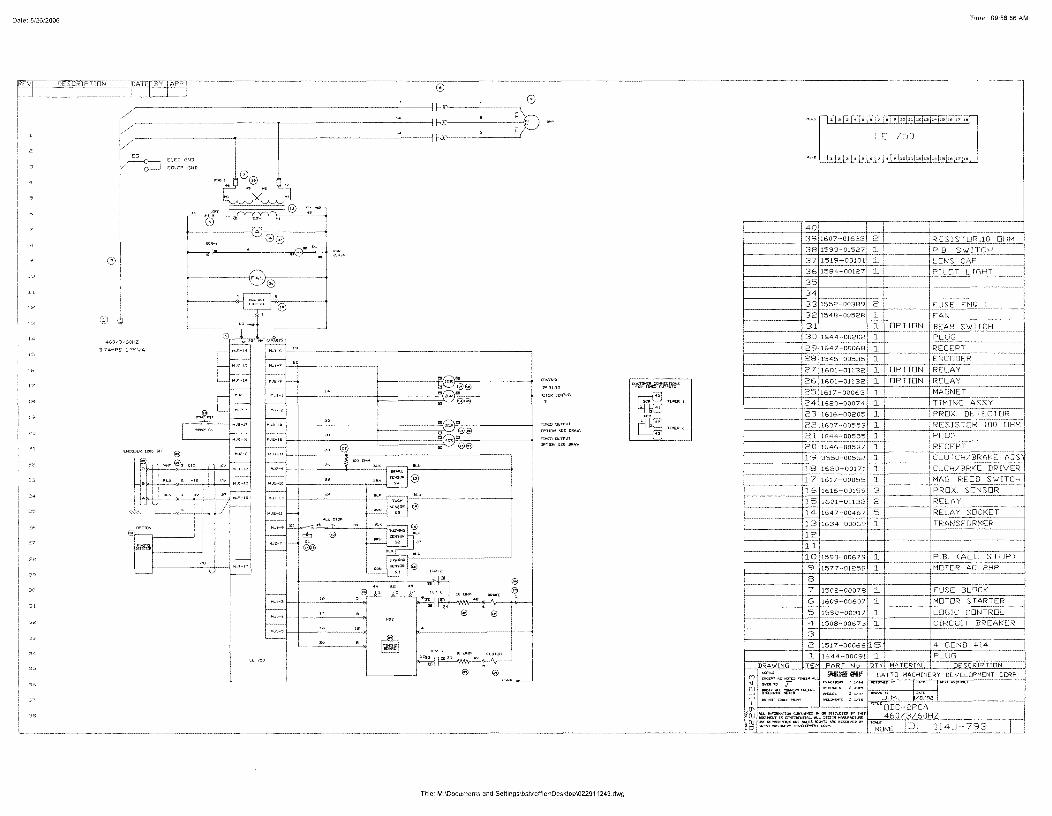
Date 5/26/2006
"
®
CD
@
e @
e @
'
.:GN!l __ _
Title: M:\Documents and Settings\bshreffler\Desktop\022911243.dwg
ro~ ,,,.,._,, ,,..,,.....,,~
Time 09:56:56 AM
1, 1, 1, I· I• 1, 1,_L'.'.L'.J:oJ>:E¥Fe•[•'1::f.;r
"'• 1 JPEC:+[• 1, I• I' 1,,1,;f,[;;_]_±.[,;~;H
40 RESISTOR,10 OHM __ _
P,B, SW'ITCH ______ _
L[NS CAP
1584-00127 J_ f:._IJ:::_0_'. LIGHT 35
34 33 1552-00389 2 - -----1--"-1-----CC-==--'-32 1548--00528 l
31 l OPTION
3 0 1644-00202 l
29 1647-00068 J. 28 1545-00535 l
Of 'TION _ , _ )TTnN
l
l
l
3
·113 I 1634-000691 l I I I l<AN'.>f llf/MU,
12 1
8
1593--0(
o7sl 1 I 6071 1 I >3171 l I
2 1517-00066 l 5
l 1644-00091 1 ~RA\-.;J_N_G·--t,c:c,-cc_ r.PccAc:cRccTc--cNc-o-, tQccT~Yt-ccM_7A_"TE"£c-~IccA;L,:-l::::·-_::::;;;:-;t;f';f_£=~--I
CORP
Date 5/26/2006 nme 09:56:57 AM
37
e
J3 -ll 0 0 llA O O 4-40S 0 0 BA 0-0 1-5S 0-0 6A 0 0 3A
J2 0-0 ARM 0 0 TACH
Ml-OPEN M2-CLOSED BRAKE ENGAGED M2-0PEN Ml-CLOSED CLUTCH ENGAGED
_jl
230 115
\0
Title; M:\Documents and Settings\bshreffler\Desktop\022904751.dwg
41 40 39 38
E ~ 35 34 33 32 31 30 29 28 27 26 25 24 23 22 21
~ 19
18 17 16 15 14 13 12
8
2
1593··01527 l 1617-00063
3550-00503 l 3570-00798 l 1519-00101 l f----- r--J_~~-·00127 l 1552-01334 l 1503-00152 l
1552-023:?2 ~ 1548-00528 2
l 1502-00086 l
1552-02659 3 1545-00535 ]_
1601-01132 l 1601-01132 1 1609-00658 l ~-0-00082 l 1616-00205 l 1607 -00553 l 1644··00555 1 1646 ~ 00587 l 3550-00511 1 1620-00171 l 1617-00055 l 1616-00159 3 1601-01132 3 164 7-0046 7 5 1634-00069 l 1586--00027
1552-00737 2
1531--01091 l
1635-00712 l 1517-00066 15

Append ix I A-1
We’re Here to Help
Conair has made the largest investment in customer support in the plastics industry. Our service experts are available to help with any problem you might have installing and oper-ating your equipment. Your Conair sales representative also can help analyze the nature of your problem, assuring that it did not result from misapplication or improper use.
How to Contact Customer Serv iceTo contact Customer Service personnel, call:
NOTE: Normal operating hours are 8:00 am - 5:00 pm EST. After hours emergencyservice is available at the same phone number.
From outside the United States, call: 814-437-6861You can commission Conair service personnel to provide on-site service by contacting the Customer Service Department. Standard rates include an on-site hourly rate, with a one-day minimum plus expenses.
Before You Cal l . . .If you do have a problem, please complete the following checklist before calling Conair:
r Make sure you have all model, control type from the serial tag, and parts list numbers for your particular equipment. Service personnel will need this information to assist you.
r Make sure power is supplied to the equipment.
r Make sure that all connectors and wires within and between control systems and related components have been installed correctly.
r Check the troubleshooting guide of this manual for a solution.
r Thoroughly examine the instruction manual(s) for associated equipment, especially controls. Each manual may have its own troubleshooting guide to help you.
Additional manuals and prints for your Conair equipment may be ordered through the Customer Service or Parts Department for a nominal fee. Most manuals can be down-loaded free of charge from the product section of the Conair website.www.conairgroup.com
0
A-2 I Append ix
Equipment GuaranteeConair guarantees the machinery and equipment on this order, for a period as defined in the quotation from date of shipment, against defects in material and workmanship under the normal use and service for which it was recommended (except for parts that are typi-cally replaced after normal usage, such as filters, liner plates, etc.). Conair’s guarantee is limited to replacing, at our option, the part or parts determined by us to be defective after examination. The customer assumes the cost of transportation of the part or parts to and from the factory.
Performance WarrantyConair warrants that this equipment will perform at or above the ratings stated in specific quotations covering the equipment or as detailed in engineering specifications, provided the equipment is applied, installed, operated, and maintained in the recommended manner as outlined in our quotation or specifications.
Should performance not meet warranted levels, Conair at its discretion will exercise one of the following options:
• Inspect the equipment and perform alterations or adjustments to satisfy performanceclaims. (Charges for such inspections and corrections will be waived unless failureto meet warranty is due to misapplication, improper installation, poor maintenancepractices, or improper operation.)
• Replace the original equipment with other Conair equipment that will meet originalperformance claims at no extra cost to the customer.
• Refund the invoiced cost to the customer. Credit is subject to prior notice by the cus-tomer at which time a Return Goods Authorization Number (RGA) will be issued byConair’s Service Department. Returned equipment must be well crated and in properoperating condition, including all parts. Returns must be prepaid.
Purchaser must notify Conair in writing of any claim and provide a customer receipt and other evidence that a claim is being made.
Warranty L imitat ionsExcept for the Equipment Guarantee and Performance Warranty stated above, Conair disclaims all other warranties with respect to the equipment, express or implied, arising by operation of law, course of dealing, usage of trade or otherwise, including but not limited to the implied warranties of merchantability and fitness for a particular purpose.
Related Documents


![[CO] EXTRUDER](https://static.cupdf.com/doc/110x72/6254afa501a5a4553c5e5652/co-extruder.jpg)


