UG0693 User Guide Image Edge Detection

Welcome message from author
This document is posted to help you gain knowledge. Please leave a comment to let me know what you think about it! Share it to your friends and learn new things together.
Transcript

UG0693User Guide
Image Edge Detection

50200693. 4.0 2/19
Microsemi HeadquartersOne Enterprise, Aliso Viejo,CA 92656 USAWithin the USA: +1 (800) 713-4113 Outside the USA: +1 (949) 380-6100Sales: +1 (949) 380-6136Fax: +1 (949) 215-4996Email: [email protected]
©2019 Microsemi, a wholly owned
subsidiary of Microchip Technology Inc. All
rights reserved. Microsemi and the
Microsemi logo are registered trademarks of
Microsemi Corporation. All other trademarks
and service marks are the property of their
respective owners.
Microsemi makes no warranty, representation, or guarantee regarding the information contained herein or the suitability of its products and services for any particular purpose, nor does Microsemi assume any liability whatsoever arising out of the application or use of any product or circuit. The products sold hereunder and any other products sold by Microsemi have been subject to limited testing and should not be used in conjunction with mission-critical equipment or applications. Any performance specifications are believed to be reliable but are not verified, and Buyer must conduct and complete all performance and other testing of the products, alone and together with, or installed in, any end-products. Buyer shall not rely on any data and performance specifications or parameters provided by Microsemi. It is the Buyer’s responsibility to independently determine suitability of any products and to test and verify the same. The information provided by Microsemi hereunder is provided “as is, where is” and with all faults, and the entire risk associated with such information is entirely with the Buyer. Microsemi does not grant, explicitly or implicitly, to any party any patent rights, licenses, or any other IP rights, whether with regard to such information itself or anything described by such information. Information provided in this document is proprietary to Microsemi, and Microsemi reserves the right to make any changes to the information in this document or to any products and services at any time without notice.
About Microsemi
Microsemi, a wholly owned subsidiary of Microchip Technology Inc. (Nasdaq: MCHP), offers a comprehensive portfolio of semiconductor and system solutions for aerospace & defense, communications, data center and industrial markets. Products include high-performance and radiation-hardened analog mixed-signal integrated circuits, FPGAs, SoCs and ASICs; power management products; timing and synchronization devices and precise time solutions, setting the world's standard for time; voice processing devices; RF solutions; discrete components; enterprise storage and communication solutions, security technologies and scalable anti-tamper products; Ethernet solutions; Power-over-Ethernet ICs and midspans; as well as custom design capabilities and services. Learn more at www.microsemi.com.

Microsemi Proprietary UG0693 User Guide Revision 4.0 iii
Contents
1 Revision History . . . . . . . . . . . . . . . . . . . . . . . . . . . . . . . . . . . . . . . . . . . . . . . . . . . . . 11.1 Revision 4.0 . . . . . . . . . . . . . . . . . . . . . . . . . . . . . . . . . . . . . . . . . . . . . . . . . . . . . . . . . . . . . . . . . . . . . . . 1
1.2 Revision 3.0 . . . . . . . . . . . . . . . . . . . . . . . . . . . . . . . . . . . . . . . . . . . . . . . . . . . . . . . . . . . . . . . . . . . . . . . 1
1.3 Revision 2.0 . . . . . . . . . . . . . . . . . . . . . . . . . . . . . . . . . . . . . . . . . . . . . . . . . . . . . . . . . . . . . . . . . . . . . . . 1
1.4 Revision 1.0 . . . . . . . . . . . . . . . . . . . . . . . . . . . . . . . . . . . . . . . . . . . . . . . . . . . . . . . . . . . . . . . . . . . . . . . 1
2 Image Edge Detection . . . . . . . . . . . . . . . . . . . . . . . . . . . . . . . . . . . . . . . . . . . . . . . . 2
3 Hardware Implementation . . . . . . . . . . . . . . . . . . . . . . . . . . . . . . . . . . . . . . . . . . . . . 33.1 Write LSRAM . . . . . . . . . . . . . . . . . . . . . . . . . . . . . . . . . . . . . . . . . . . . . . . . . . . . . . . . . . . . . . . . . . . . . . 3
3.2 Read LSRAM . . . . . . . . . . . . . . . . . . . . . . . . . . . . . . . . . . . . . . . . . . . . . . . . . . . . . . . . . . . . . . . . . . . . . . 3
3.3 Sobel Filter . . . . . . . . . . . . . . . . . . . . . . . . . . . . . . . . . . . . . . . . . . . . . . . . . . . . . . . . . . . . . . . . . . . . . . . . 3
4 Interfaces . . . . . . . . . . . . . . . . . . . . . . . . . . . . . . . . . . . . . . . . . . . . . . . . . . . . . . . . . . 44.1 Ports . . . . . . . . . . . . . . . . . . . . . . . . . . . . . . . . . . . . . . . . . . . . . . . . . . . . . . . . . . . . . . . . . . . . . . . . . . . . . 4
4.2 Configuration Parameters . . . . . . . . . . . . . . . . . . . . . . . . . . . . . . . . . . . . . . . . . . . . . . . . . . . . . . . . . . . . 4
5 Timing Diagram . . . . . . . . . . . . . . . . . . . . . . . . . . . . . . . . . . . . . . . . . . . . . . . . . . . . . 5
6 Testbench . . . . . . . . . . . . . . . . . . . . . . . . . . . . . . . . . . . . . . . . . . . . . . . . . . . . . . . . . 66.1 Simulation Steps . . . . . . . . . . . . . . . . . . . . . . . . . . . . . . . . . . . . . . . . . . . . . . . . . . . . . . . . . . . . . . . . . . . 6
7 Simulation Result . . . . . . . . . . . . . . . . . . . . . . . . . . . . . . . . . . . . . . . . . . . . . . . . . . . 10
8 Resource Utilization . . . . . . . . . . . . . . . . . . . . . . . . . . . . . . . . . . . . . . . . . . . . . . . . . 11

Microsemi Proprietary UG0693 User Guide Revision 4.0 iv
Figures
Figure 1 Sobel Operator Horizontal and Vertical Kernels . . . . . . . . . . . . . . . . . . . . . . . . . . . . . . . . . . . . . . . . 2Figure 2 Image Edge Detection Block Diagram . . . . . . . . . . . . . . . . . . . . . . . . . . . . . . . . . . . . . . . . . . . . . . . 3Figure 3 Timing Diagram of Edge Detection Showing Valid Input and Output Data . . . . . . . . . . . . . . . . . . . . 5Figure 4 Opening New SmartDesign TestBench . . . . . . . . . . . . . . . . . . . . . . . . . . . . . . . . . . . . . . . . . . . . . . 6Figure 5 Naming the Testbench . . . . . . . . . . . . . . . . . . . . . . . . . . . . . . . . . . . . . . . . . . . . . . . . . . . . . . . . . . . 6Figure 6 IP Location . . . . . . . . . . . . . . . . . . . . . . . . . . . . . . . . . . . . . . . . . . . . . . . . . . . . . . . . . . . . . . . . . . . . 7Figure 7 Instantiation of the IP . . . . . . . . . . . . . . . . . . . . . . . . . . . . . . . . . . . . . . . . . . . . . . . . . . . . . . . . . . . . 7Figure 8 Promote the Ports to Top Level . . . . . . . . . . . . . . . . . . . . . . . . . . . . . . . . . . . . . . . . . . . . . . . . . . . . 7Figure 9 Ports Promoted to Top-level . . . . . . . . . . . . . . . . . . . . . . . . . . . . . . . . . . . . . . . . . . . . . . . . . . . . . . . 8Figure 10 Generate Component Button . . . . . . . . . . . . . . . . . . . . . . . . . . . . . . . . . . . . . . . . . . . . . . . . . . . . . . 8Figure 11 The Import Files Option . . . . . . . . . . . . . . . . . . . . . . . . . . . . . . . . . . . . . . . . . . . . . . . . . . . . . . . . . . 8Figure 12 Imported File . . . . . . . . . . . . . . . . . . . . . . . . . . . . . . . . . . . . . . . . . . . . . . . . . . . . . . . . . . . . . . . . . . . 8Figure 13 Simulating Pre-Synthesis Design . . . . . . . . . . . . . . . . . . . . . . . . . . . . . . . . . . . . . . . . . . . . . . . . . . . 9Figure 14 ModelSim Simulation Window . . . . . . . . . . . . . . . . . . . . . . . . . . . . . . . . . . . . . . . . . . . . . . . . . . . . . 9Figure 15 Input Image . . . . . . . . . . . . . . . . . . . . . . . . . . . . . . . . . . . . . . . . . . . . . . . . . . . . . . . . . . . . . . . . . . . 10Figure 16 Output Image . . . . . . . . . . . . . . . . . . . . . . . . . . . . . . . . . . . . . . . . . . . . . . . . . . . . . . . . . . . . . . . . . 10
Microsemi Proprietary UG0693 User Guide Revision 4.0 v
Tables
Table 1 Input and Output Ports . . . . . . . . . . . . . . . . . . . . . . . . . . . . . . . . . . . . . . . . . . . . . . . . . . . . . . . . . . . 4Table 2 Configuration Parameters . . . . . . . . . . . . . . . . . . . . . . . . . . . . . . . . . . . . . . . . . . . . . . . . . . . . . . . . . 4Table 3 Testbench Configuration Parameters . . . . . . . . . . . . . . . . . . . . . . . . . . . . . . . . . . . . . . . . . . . . . . . . 6Table 4 Resource Utilization on PolarFire . . . . . . . . . . . . . . . . . . . . . . . . . . . . . . . . . . . . . . . . . . . . . . . . . . 11Table 5 Resource Utilization on SmartFusion2 . . . . . . . . . . . . . . . . . . . . . . . . . . . . . . . . . . . . . . . . . . . . . . 11

Revision History
Microsemi Proprietary UG0693 User Guide Revision 4.0 1
1 Revision History
The revision history describes the changes that were implemented in the document. The changes are listed by revision, starting with the most current publication.
1.1 Revision 4.0The following is a summary of the changes made in this revision.
• Updated the block diagram and timing diagrams, see Figure 2, page 3, Figure 3, page 5.• Updated the tables in Interfaces, page 4, Resource Utilization, page 11.• Updated Testbench, page 6.• Updated the input and output image of simulation, see Simulation Result, page 10.
1.2 Revision 3.0Updated the resource utilization report.
1.3 Revision 2.0Added the steps to simulate the core using the testbench.
1.4 Revision 1.0The first publication of this document.

Image Edge Detection
Microsemi Proprietary UG0693 User Guide Revision 4.0 2
2 Image Edge Detection
Image Edge Detection is an image processing method for feature detection and extraction. This method is used to identify points in a digital image where the brightness changes sharply and discontinues. The edge detection method reduces the amount of data in an image and preserves the structural properties for further processing. In a gray level image, the edge is a local feature with in a neighborhood separate regions.The gray level is more or less uniform with in different values on the two sides of the edge. For a noisy image, it is difficult to detect edges as both edge and noise contains high frequency contents, which results in blurred and distorted images.
Microsemi offers the Image Edge Detection IP that enables designers to use the edge detection for image processing.
The Image Edge Detection IP implements Sobel filter, which is a classical algorithm in the field of image and video processing for the extraction of object edges. Sobel filter works on the premise of computing an estimate of the first derivative of an image to extract the edge information. By computing the x and y direction derivatives of a specific pixel against a neighborhood of surrounding pixels, it is possible to extract the boundary between two distinct elements in an image. Due to the computational load of calculating derivatives using the squaring and square root operators, fixed coefficient masks are adopted as a suitable approximation in computing the derivative at a specific point. In the case of Sobel, the masks used are shown in the following figure.
Figure 1 • Sobel Operator Horizontal and Vertical Kernels
These kernels can be combined together to find the absolute magnitude of the gradient at each point. The gradient magnitude is computed using:
Typically an approximate magnitude is computed using:
This is much faster to compute. The Sobel operator has the advantage of simplicity in calculation.
-1 0 1
-2 0 2
-1 0 1
1 2 1
0 0 0
-1 -2 1
Vertical Mask Horizontal Mask
G Gx2 Gy2+=
G Gx Gy+=
Hardware Implementation
Microsemi Proprietary UG0693 User Guide Revision 4.0 3
3 Hardware Implementation
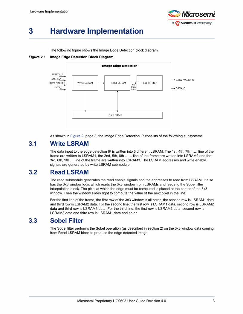
The following figure shows the Image Edge Detection block diagram.
Figure 2 • Image Edge Detection Block Diagram
As shown in Figure 2, page 3, the Image Edge Detection IP consists of the following subsystems:
3.1 Write LSRAMThe data input to the edge detection IP is written into 3 different LSRAM. The 1st, 4th, 7th…… line of the frame are written to LSRAM1, the 2nd, 5th, 8th …… line of the frame are written into LSRAM2 and the 3rd, 6th, 9th … line of the frame are written into LSRAM3. The LSRAM addresses and write enable signals are generated by write LSRAM submodule.
3.2 Read LSRAMThe read submodule generates the read enable signals and the addresses to read from LSRAM. It also has the 3x3 window logic which reads the 3x3 window from LSRAMs and feeds to the Sobel filter interpolation block. The pixel at which the edge must be computed is placed at the center of the 3x3 window. Then the window slides right to compute the value of the next pixel in the line.
For the first line of the frame, the first row of the 3x3 window is all zeros, the second row is LSRAM1 data and third row is LSRAM2 data. For the second line, the first row is LSRAM1 data, second row is LSRAM2 data and third row is LSRAM3 data. For the third line, the first row is LSRAM2 data, second row is LSRAM3 data and third row is LSRAM1 data and so on.
3.3 Sobel FilterThe Sobel filter performs the Sobel operation (as described in section 2) on the 3x3 window data coming from Read LSRAM block to produce the edge detected image.
Image Edge Detection
Read LSRAMWrite LSRAM Sobel Filter
3 x LSRAM
3x3Data
Matrix
DATA_VALID_O
DATA_O
RESETN_I
SYS_CLK_I
DATA_VALID_I
DATA_I

Interfaces
Microsemi Proprietary UG0693 User Guide Revision 4.0 4
4 Interfaces
This section describes the input/output ports and the configuration parameters of the Image Edge Detection IP.
4.1 PortsThe following table lists the input and output ports.
4.2 Configuration ParametersThe following table lists the configuration parameters of the Image Edge Detection IP. These are generic parameters and can vary based on the application requirements.
Table 1 • Input and Output Ports
Port Name Type Width Description
RESETN_I Input 1bit Active low asynchronous reset signal to design
SYS_CLK_I Input 1bit System clock
DATA_VALID_I Input 1bit Asserted high when input data is valid
DATA_I Input G_DATA_WIDTH bits Input RGB data
DATA_VALID_O Output 1bit Asserted high when output data is valid
DATA_O Output G_DATA_WIDTH bits Provides the edge detected output
Table 2 • Configuration Parameters
Name Description
G_DATA_WIDTH Width of each pixel
G_RAM_SIZE Size of the RAM to store one horizontal lineChoose values which are powers of 2, such as 2048, and 4096.
Timing Diagram
Microsemi Proprietary UG0693 User Guide Revision 4.0 5
5 Timing Diagram
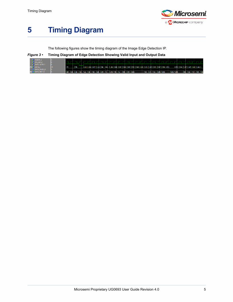
The following figures show the timing diagram of the Image Edge Detection IP.
Figure 3 • Timing Diagram of Edge Detection Showing Valid Input and Output Data

Testbench
6 Testbench
A testbench is provided to check the functionality of the Image Edge Detection IP. The following table lists the parameters that can be configured according to the application.
6.1 Simulation StepsThe following steps describe how to simulate the core using the testbench.
1. On the Design Flow window, expand Create Design and open Create SmartDesign testbench as shown in the following figure.
Figure 4 • Opening New SmartDesign TestBench
2. Enter a name for the SmartDesign testbench as shown in the following figure.
Figure 5 • Naming the Testbench
Table 3 • Testbench Configuration Parameters
Name Description
CLKPERIOD Clock Period
HEIGHT Height of the image
WIDTH Width of the image
WAIT Amount of delay after each line of input image
DATAWIDTH Width of each pixel
IMAGE_FILE_NAME Input image name
Microsemi Proprietary UG0693 User Guide Revision 4.0 6

Testbench
3. Go to the Catalog tab and expand Solutions-Video. After that, drag the Image Edge Detection IP to the testbench canvas. The Image Edge Detection IP is highlighted in the following figure.
Figure 6 • IP Location
4. After dragging the IP to the testbench canvas, the IP appears as shown in the following figure.
Figure 7 • Instantiation of the IP
5. Select all of the ports and promote them to top level using the Promote to Top Level option, as shown in the following figure.
Figure 8 • Promote the Ports to Top Level
6. The ports are promoted to the top level, as shown in the following figure.
Microsemi Proprietary UG0693 User Guide Revision 4.0 7

Testbench
Figure 9 • Ports Promoted to Top-level
7. Click Generate Component to generate the testbench component. Generate Component is highlighted in the following figure.
Figure 10 • Generate Component Button
8. Go to the Files tab and select simulation > Import Files as shown in the following figure.
Figure 11 • The Import Files Option
9. Import the RGB file from the following path:..\<Project_name>\component\Microsemi\SolutionCore\Image_Edge_Detection\3.0.0\Stimulus
The imported file is listed under simulation as shown in Figure 12, page 8.
Figure 12 • Imported File
Note: To import a different file, browse the folder that contains the required file, and click Open.
10. Go to the Stimulus Hierarchy tab and select edge_detection_test (edge_detection_tb.v) > Simulate Pre-Synth Design > Open Interactively. The core is simulated for one frame.
Microsemi Proprietary UG0693 User Guide Revision 4.0 8

Testbench
Figure 13 • Simulating Pre-Synthesis Design
11. ModelSim opens with the testbench file as shown in the following figure.
Figure 14 • ModelSim Simulation Window
If the simulation is interrupted due to the runtime limit specified in the DO file, use the run -all command to complete the simulation.
The testbench output image file appears in the Files/simulation folder after the simulation completes.
Microsemi Proprietary UG0693 User Guide Revision 4.0 9

Simulation Result
Microsemi Proprietary UG0693 User Guide Revision 4.0 10
7 Simulation Result
This section shows an image before and after being processed using the Image Edge Detection IP.
The following figure shows the input image.
Figure 15 • Input Image
The following figure shows the output image after being processed using the Image Edge Detection IP.
Figure 16 • Output Image

Resource Utilization
Microsemi Proprietary UG0693 User Guide Revision 4.0 11
8 Resource Utilization
Image Edge Detection is implemented on the SmartFusion®2 system-on-chip (SoC) field programmable gate array (FPGA) device (M2S150T-1152 FC package) and PolarFire® FPGA (MPF300TS- 1FCG1152E package). The following figure shows the resource utilization report after synthesis.
Table 4 • Resource Utilization on PolarFire1
1. For G_DATA_WIDTH = 8 and G_RAM_SIZE = 2048.
Resource Usage
DFFs 384
4LUTs 671
LSRAM 3
MACC 0
Table 5 • Resource Utilization on SmartFusion21
1. For G_DATA_WIDTH = 8 and G_RAM_SIZE = 2048.
Resource Usage
DFFs 400
4LUTs 713
RAM1K18 3
RAM64x18 0
MACC 0
Related Documents