************************************************************************** USACE / NAVFAC / AFCEC / NASA UFGS-46 30 13 (February 2011) ----------------------------- Preparing Activity: USACE Superseding UFGS-44 44 53 (October 2007) UNIFIED FACILITIES GUIDE SPECIFICATIONS References are in agreement with UMRL dated January 2020 ************************************************************************** SECTION TABLE OF CONTENTS DIVISION 46 - WATER AND WASTEWATER EQUIPMENT SECTION 46 30 13 ADVANCED OXIDATION PROCESSES (AOP) 02/11 PART 1 GENERAL 1.1 REFERENCES 1.2 SUBMITTALS 1.3 QUALIFICATIONS 1.3.1 Contractor 1.3.2 Equipment Manufacturer 1.3.3 Ultraviolet (UV) Oxidation System Supplier 1.3.4 Manufacturer's Representative 1.3.5 Welding 1.4 REGULATORY REQUIREMENTS 1.5 PRE-SUBMITTAL CONFERENCE 1.6 DELIVERY, STORAGE, AND HANDLING PART 2 PRODUCTS 2.1 SYSTEM DESCRIPTION 2.1.1 Design Requirements 2.1.2 Performance Requirements 2.1.3 Treatability Testing 2.2 STANDARD PRODUCTS 2.3 NAMEPLATES 2.4 MATERIALS 2.4.1 Plates, Shapes and Bars 2.4.2 Pipe and Fittings 2.4.2.1 Stainless Steel Pipe 2.4.2.2 Polyvinyl Chloride (PVC) Pipe 2.4.2.3 Polytetrafluoroethylene (PTFE) Pipe and Tubing 2.4.2.4 Polyvinylidene Fluoride (PVDF) Pipe and Tubing 2.4.2.5 Copper Pipe 2.4.3 Pipe Hangers and Supports 2.4.4 Stainless Steel Gas Tubing and Fittings 2.4.5 Valves 2.4.5.1 Liquid Oxygen (LOX) 2.4.5.2 Gate 2.4.5.3 Ball SECTION 46 30 13 Page 1

Welcome message from author
This document is posted to help you gain knowledge. Please leave a comment to let me know what you think about it! Share it to your friends and learn new things together.
Transcript

**************************************************************************USACE / NAVFAC / AFCEC / NASA UFGS- 46 30 13 ( Febr uar y 2011) - - - - - - - - - - - - - - - - - - - - - - - - - - - - -Pr epar i ng Act i v i t y: USACE Super sedi ng UFGS- 44 44 53 ( Oct ober 2007)
UNI FI ED FACI LI TI ES GUI DE SPECI FI CATI ONS
Ref er ences ar e i n agr eement wi t h UMRL dat ed Januar y 2020**************************************************************************
SECTION TABLE OF CONTENTS
DIVISION 46 - WATER AND WASTEWATER EQUIPMENT
SECTION 46 30 13
ADVANCED OXIDATION PROCESSES (AOP)
02/11
PART 1 GENERAL
1.1 REFERENCES 1.2 SUBMITTALS 1.3 QUALIFICATIONS 1.3.1 Contractor 1.3.2 Equipment Manufacturer 1.3.3 Ultraviolet (UV) Oxidation System Supplier 1.3.4 Manufacturer's Representative 1.3.5 Welding 1.4 REGULATORY REQUIREMENTS 1.5 PRE-SUBMITTAL CONFERENCE 1.6 DELIVERY, STORAGE, AND HANDLING
PART 2 PRODUCTS
2.1 SYSTEM DESCRIPTION 2.1.1 Design Requirements 2.1.2 Performance Requirements 2.1.3 Treatability Testing 2.2 STANDARD PRODUCTS 2.3 NAMEPLATES 2.4 MATERIALS 2.4.1 Plates, Shapes and Bars 2.4.2 Pipe and Fittings 2.4.2.1 Stainless Steel Pipe 2.4.2.2 Polyvinyl Chloride (PVC) Pipe 2.4.2.3 Polytetrafluoroethylene (PTFE) Pipe and Tubing 2.4.2.4 Polyvinylidene Fluoride (PVDF) Pipe and Tubing 2.4.2.5 Copper Pipe 2.4.3 Pipe Hangers and Supports 2.4.4 Stainless Steel Gas Tubing and Fittings 2.4.5 Valves 2.4.5.1 Liquid Oxygen (LOX) 2.4.5.2 Gate 2.4.5.3 Ball
SECTION 46 30 13 Page 1

2.4.5.4 Check 2.4.6 Injectors 2.4.7 Diffusers 2.4.8 Couplings 2.4.9 Insulating Joints 2.4.10 In Pipeline Static Mixers 2.4.11 Bolts, Nuts, Anchors and Fasteners 2.5 MANUFACTURED UNITS 2.5.1 Swing Adsorption Oxygen Generation System 2.5.2 Liquid Oxygen (LOX) Storage and Supply System 2.5.2.1 LOX Storage Tanks 2.5.2.2 Vaporizers 2.5.2.3 Regulators 2.5.3 Ozone Generator Air Feed System 2.5.4 Ozone Generator System 2.5.4.1 Ozone Generator Vessels 2.5.4.2 Dielectric Tubes 2.5.5 Ozone Destruct System 2.5.6 Hydrogen Peroxide System 2.5.7 Redox Potential Meter 2.5.8 pH Probe 2.5.9 Ozone Monitors 2.5.9.1 Vapor Phase 2.5.9.2 Liquid Phase 2.5.10 Temperature Sensors 2.5.11 Compressors 2.5.12 Blowers 2.5.13 Dew Point Monitor 2.5.14 Pressure Gauges 2.5.15 Sampling Ports 2.5.16 Gas Flow Meters 2.5.17 Level Monitoring 2.5.18 Reactor Vessel 2.6 ELECTRICAL 2.6.1 Motors 2.6.2 Local Controls and Panels 2.6.3 Ultraviolet Equipment Electrical Requirements 2.7 AOP CONTROL SYSTEM 2.7.1 Ozonation Control System 2.7.2 Hydrogen Peroxide Feed 2.7.3 Alarms and Interlocks 2.7.3.1 AOP System 2.7.3.2 Metering Pump 2.7.3.3 Hydrogen Peroxide Tank 2.7.3.4 Ozone System 2.7.3.5 Gas Feed System 2.7.3.6 Ozone Destruct System 2.7.3.7 Cooling Water System 2.7.3.8 Metering Accuracy 2.7.3.9 Ground Fault 2.8 SPECIAL EQUIPMENT AND TOOLS
PART 3 EXECUTION
3.1 EXAMINATION 3.2 PREPARATION 3.3 EQUIPMENT INSTALLATION 3.4 ELECTRICAL WORK 3.5 TOOLS
SECTION 46 30 13 Page 2

3.6 PAINTING/CORROSION PROTECTION 3.7 CHEMICALS 3.8 WELDING 3.9 SAMPLING AND ANALYSIS 3.9.1 Plan Details 3.9.2 Plan Calculations 3.9.3 Chemical Sampling 3.10 POSTING FRAMED INSTRUCTIONS 3.11 FIELD TESTS AND INSPECTIONS 3.11.1 AOP Reactor Vessel 3.11.2 Diffuser or Injector System 3.11.3 Leak Testing 3.11.4 Control Panel 3.11.5 Ozone Generation System 3.12 MANUFACTURER'S SERVICES 3.13 FIELD TRAINING 3.14 MAINTENANCE 3.14.1 Extra Materials 3.14.1.1 Lamps 3.14.1.2 Spare Parts 3.14.2 Maintenance Service 3.14.3 Operating Instructions
-- End of Section Table of Contents --
SECTION 46 30 13 Page 3
**************************************************************************USACE / NAVFAC / AFCEC / NASA UFGS- 46 30 13 ( Febr uar y 2011) - - - - - - - - - - - - - - - - - - - - - - - - - - - - -Pr epar i ng Act i v i t y: USACE Super sedi ng UFGS- 44 44 53 ( Oct ober 2007)
UNI FI ED FACI LI TI ES GUI DE SPECI FI CATI ONS
Ref er ences ar e i n agr eement wi t h UMRL dat ed Januar y 2020**************************************************************************
SECTION 46 30 13
ADVANCED OXIDATION PROCESSES (AOP)02/11
**************************************************************************NOTE: Thi s gui de speci f i cat i on cover s t he r equi r ement s f or l i qui d phase advanced oxi dat i on pr ocesses usi ng t i t ani um di oxi de or hydr ogen per oxi de and/ or ozone wi t h or wi t hout ul t r avi ol et light.
Adher e t o UFC 1-300-02 Uni f i ed Faci l i t i es Gui de Speci f i cat i ons ( UFGS) For mat St andar d when edi t i ng t hi s gui de speci f i cat i on or pr epar i ng new pr oj ect speci f i cat i on sect i ons. Edi t t hi s gui de speci f i cat i on f or pr oj ect speci f i c r equi r ement s by addi ng, del et i ng, or r evi s i ng t ext . For br acket ed i t ems, choose appl i cabl e i t em( s) or i nser t appr opr i at e i nf or mat i on.
Remove i nf or mat i on and r equi r ement s not r equi r ed i n r espect i ve pr oj ect , whet her or not br acket s ar e present.
Comment s, suggest i ons and r ecommended changes f or t hi s gui de speci f i cat i on ar e wel come and shoul d be submi t t ed as a Criteria Change Request (CCR) .
**************************************************************************
PART 1 GENERAL
1.1 REFERENCES
**************************************************************************NOTE: Thi s par agr aph i s used t o l i s t t he publ i cat i ons c i t ed i n t he t ext of t he gui de speci f i cat i on. The publ i cat i ons ar e r ef er r ed t o i n t he t ext by basi c desi gnat i on onl y and l i s t ed i n t hi s par agr aph by or gani zat i on, desi gnat i on, dat e, and t i t l e.
Use t he Ref er ence Wi zar d' s Check Ref er ence f eat ur e when you add a Ref er ence I dent i f i er ( RI D) out si de of t he Sect i on' s Ref er ence Ar t i c l e t o aut omat i cal l y pl ace t he r ef er ence i n t he Ref er ence Ar t i c l e. Al so
SECTION 46 30 13 Page 4

use t he Ref er ence Wi zar d' s Check Ref er ence f eat ur e t o updat e t he i ssue dat es.
Ref er ences not used i n t he t ext wi l l aut omat i cal l y be del et ed f r om t hi s sect i on of t he pr oj ect speci f i cat i on when you choose t o r econci l e r ef er ences i n t he publ i sh pr i nt pr ocess.
**************************************************************************
The publications listed below form a part of this specification to the extent referenced. The publications are referred to within the text by the basic designation only.
AMERICAN SOCIETY OF MECHANICAL ENGINEERS (ASME)
ASME B16.5 (2017) Pipe Flanges and Flanged Fittings NPS 1/2 Through NPS 24 Metric/Inch Standard
ASME B16.9 (2018) Factory-Made Wrought Buttwelding Fittings
ASME B16.18 (2018) Cast Copper Alloy Solder Joint Pressure Fittings
ASME B16.22 (2018) Standard for Wrought Copper and Copper Alloy Solder Joint Pressure Fittings
ASME B31.1 (2018) Power Piping
ASME B40.100 (2013) Pressure Gauges and Gauge Attachments
ASME BPVC SEC IX (2017; Errata 2018) BPVC Section IX-Welding, Brazing and Fusing Qualifications
ASME BPVC SEC VIII D1 (2017) BPVC Section VIII-Rules for Construction of Pressure Vessels Division 1
AMERICAN WELDING SOCIETY (AWS)
AWS B2.1/B2.1M (2014; Errata 2015) Specification for Welding Procedure and Performance Qualification
AWS D1.1/D1.1M (2015; Errata 1 2015; Errata 2 2016) Structural Welding Code - Steel
ASTM INTERNATIONAL (ASTM)
ASTM A36/A36M (2014) Standard Specification for Carbon Structural Steel
ASTM A53/A53M (2018) Standard Specification for Pipe, Steel, Black and Hot-Dipped, Zinc-Coated, Welded and Seamless
ASTM A182/A182M (2019a) Standard Specification for Forged or Rolled Alloy and Stainless Steel Pipe
SECTION 46 30 13 Page 5

Flanges, Forged Fittings, and Valves and Parts for High-Temperature Service
ASTM A269/A269M (2015; R 2019) Standard Specification for Seamless and Welded Austenitic Stainless Steel Tubing for General Service
ASTM A276/A276M (2017) Standard Specification for Stainless Steel Bars and Shapes
ASTM A312/A312M (2019) Standard Specification for Seamless, Welded, and Heavily Cold Worked Austenitic Stainless Steel Pipes
ASTM A403/A403M (2019a) Standard Specification for Wrought Austenitic Stainless Steel Piping Fittings
ASTM A774/A774M (2014) Standard Specification for As-Welded Wrought Austenitic Stainless Steel Fittings for General Corrosive Service at Low and Moderate Temperatures
ASTM A778/A778M (2016) Standard Specification for Welded, Unannealed Austenitic Stainless Steel Tubular Products
ASTM B32 (2008; R 2014) Standard Specification for Solder Metal
ASTM B88 (2016) Standard Specification for Seamless Copper Water Tube
ASTM B88M (2018) Standard Specification for Seamless Copper Water Tube (Metric)
ASTM B209 (2014) Standard Specification for Aluminum and Aluminum-Alloy Sheet and Plate
ASTM B209M (2014) Standard Specification for Aluminum and Aluminum-Alloy Sheet and Plate (Metric)
ASTM D1710 (2008) Extruded and Compression Molded Polytetrafluoroethylene (PTFE) Rod and Heavy-Walled Tubing
ASTM D1785 (2015; E 2018) Standard Specification for Poly(Vinyl Chloride) (PVC), Plastic Pipe, Schedules 40, 80, and 120
ASTM D2241 (2015) Standard Specification for Poly(Vinyl Chloride) (PVC) Pressure-Rated Pipe (SDR Series)
ASTM D2564 (2012) Standard Specification for Solvent Cements for Poly(Vinyl Chloride) (PVC) Plastic Piping Systems
ASTM D3222 (2018a) Standard Specification for Unmodified Poly(Vinylidene Fluoride)
SECTION 46 30 13 Page 6

(PVDF) Molding Extrusion and Coating Materials
ASTM F593 (2017) Standard Specification for Stainless Steel Bolts, Hex Cap Screws, and Studs
COMPRESSED AIR AND GAS INSTITUTE (CAGI)
CAGI B19.1 (2010) Safety Standard for Compressor Systems
COMPRESSED GAS ASSOCIATION (CGA)
CGA G-4.1 (2009) Cleaning Equipment for Oxygen Service; 6th Edition
CGA G-4.4 (2012) Oxygen Pipeline Systems; 4th Edition
CGA HB (1999) Handbook of Compressed Gases; 4th Edition
INTERNATIONAL SOCIETY OF AUTOMATION (ISA)
ANSI/ISA 5.1 (2009) Instrumentation Symbols and Identification
MANUFACTURERS STANDARDIZATION SOCIETY OF THE VALVE AND FITTINGS INDUSTRY (MSS)
MSS SP-43 (2013) Wrought Stainless Steel Butt-Welding Fittings
MSS SP-58 (2018) Pipe Hangers and Supports - Materials, Design and Manufacture, Selection, Application, and Installation
NATIONAL ELECTRICAL MANUFACTURERS ASSOCIATION (NEMA)
NEMA 250 (2018) Enclosures for Electrical Equipment (1000 Volts Maximum)
NEMA ICS 6 (1993; R 2016) Industrial Control and Systems: Enclosures
NATIONAL FIRE PROTECTION ASSOCIATION (NFPA)
NFPA 55 (2016; TIA 16-1; TIA 16-2) Compressed Gases and Cryogenic Fluids Codes
NFPA 70 (2017; ERTA 1-2 2017; TIA 17-1; TIA 17-2; TIA 17-3; TIA 17-4; TIA 17-5; TIA 17-6; TIA 17-7; TIA 17-8; TIA 17-9; TIA 17-10; TIA 17-11; TIA 17-12; TIA 17-13; TIA 17-14; TIA 17-15; TIA 17-16; TIA 17-17 ) National Electrical Code
SECTION 46 30 13 Page 7
U.S. DEPARTMENT OF DEFENSE (DOD)
UFC 3-301-01 (2019) Structural Engineering
1.2 SUBMITTALS
**************************************************************************NOTE: Revi ew submi t t al descr i pt i on ( SD) def i ni t i ons i n Sect i on 01 33 00 SUBMI TTAL PROCEDURES and edi t t he f ol l owi ng l i s t t o r ef l ect onl y t he submi t t al s r equi r ed f or t he pr oj ect .
The Gui de Speci f i cat i on t echni cal edi t or s have desi gnat ed t hose i t ems t hat r equi r e Gover nment appr oval , due t o t hei r compl exi t y or cr i t i cal i t y, wi t h a " G. " Gener al l y, ot her submi t t al i t ems can be r evi ewed by t he Cont r act or ' s Qual i t y Cont r ol Syst em. Onl y add a “ G” t o an i t em, i f t he submi t t al i s suf f i c i ent l y i mpor t ant or compl ex i n cont ext of t he pr oj ect .
For submi t t al s r equi r i ng Gover nment appr oval on Ar my pr oj ect s, a code of up t o t hr ee char act er s wi t hi n t he submi t t al t ags may be used f ol l owi ng t he " G" desi gnat i on t o i ndi cat e t he appr ovi ng aut hor i t y. Codes f or Ar my pr oj ect s usi ng t he Resi dent Management Syst em ( RMS) ar e: " AE" f or Ar chi t ect - Engi neer ; " DO" f or Di st r i ct Of f i ce ( Engi neer i ng Di v i s i on or ot her or gani zat i on i n t he Di st r i ct Of f i ce) ; " AO" f or Ar ea Of f i ce; " RO" f or Resi dent Of f i ce; and " PO" f or Pr oj ect Of f i ce. Codes f ol l owi ng t he " G" t ypi cal l y ar e not used f or Navy, Ai r For ce, and NASA pr oj ect s.
The " S" f ol l owi ng a submi t t al i t em i ndi cat es t hat t he submi t t al i s r equi r ed f or t he Sust ai nabi l i t y eNot ebook t o f ul f i l l f eder al l y mandat ed sust ai nabl e r equi r ement s i n accor dance wi t h Sect i on 01 33 29 SUSTAI NABI LI TY REPORTI NG. Locat e t he " S" submi t t al under t he SD number t hat best descr i bes t he submi t t al i t em.
Choose t he f i r st br acket ed i t em f or Navy, Ai r For ce and NASA pr oj ect s, or choose t he second br acket ed i t em f or Ar my pr oj ect s.
**************************************************************************
Government approval is required for submittals with a "G" designation; submittals not having a "G" designation are for [Contractor Quality Control approval.][information only. When used, a designation following the "G" designation identifies the office that will review the submittal for the Government.] Submittals with an "S" are for inclusion in the Sustainability eNotebook, in conformance to Section 01 33 29 SUSTAINABILITY REPORTING. Submit the following in accordance with Section 01 33 00 SUBMITTAL PROCEDURES:
SD-02 Shop Drawings
AOP System ; G[, [_____]]
SECTION 46 30 13 Page 8
Air Preparation System ; G[, [_____]]
Oxygen Generation System ; G[, [_____]]
LOX Storage System ; G[, [_____]]
Ozone Generation System ; G[, [_____]]
Reactor Vessel ; G[, [_____]]
Metering Pump ; G[, [_____]]
Local Controls and Panels ; G[, [_____]]
Liquid Process Tank ; G[, [_____]]
Maintenance ; G[, [_____]]
Drawings showing shop and erection details and chemical application locations; including cuts, codes, connections, holes, bolts, welds, anchorage, installation details, wiring diagrams, schematic diagrams, component identification tables and directory, and clearances for maintenance and operations.
SD-03 Product Data
AOP System ; G[, [_____]]
Calculations ; G[, [_____]]
Commissioning/Demonstration Plan ; G[, [_____]]
Manufactured Units
Performance Requirements ; G[, [_____]]
Qualifications ; G[, [_____]]
SD-06 Test Reports
Performance Requirements ; G[, [_____]]
SD-07 Certificates
AOP System
Field Training
SD-10 Operation and Maintenance Data
AOP System ; G[, [_____]]
Maintenance ; G[, [_____]]
1.3 QUALIFICATIONS
**************************************************************************NOTE: Desi gner shoul d edi t t he subsequent
SECTION 46 30 13 Page 9

par agr aphs and r emove r equi r ement s not appl i cabl e t o t he pr oj ect .
**************************************************************************1.3.1 Contractor
Provide documentation of a minimum of [3] [_____] years of experience in the construction of water, wastewater, industrial wastewater, or hazardous and toxic waste water treatment facilities. The Contractor is responsible for installation and start-up of the AOP equipment supplied, as well as operator training.
1.3.2 Equipment Manufacturer
Submit a statement by the equipment manufacturer listing any exception to or deviations from the contract drawings and specifications. Written evidence that equipment and accessories are a product of a qualified and experienced manufacturer. Statement indicating the system is capable of treating the wastes to the levels identified.
1.3.3 Ultraviolet (UV) Oxidation System Supplier
Equipment provided shall duplicate equipment that has been in satisfactory service for a minimum of [2] [_____] years prior to bid opening. The UV oxidation system supplier shall be responsible for furnishing a complete prepackaged system. The supplier need not manufacture the entire system, but shall coordinate the selection, assembly, installation, and testing of the entire system as specified.
1.3.4 Manufacturer's Representative
Provide services, as specified, of a qualified manufacturer's field representative experienced in the installation, adjustment, and operation of the equipment furnished and who has complete knowledge of the proper operation and maintenance of the system. Include a statement indicating the operators designated to train the on site operators have been trained to operate the installed equipment.
1.3.5 Welding
Perform welding following qualified procedures, using performance qualified welders and welding operators. Furnish a copy of qualified procedures and a list of names and identification symbols of qualified welders and welding operators to the Contracting Officer prior to beginning any work on the AOP equipment.
1.4 REGULATORY REQUIREMENTS
The AOP system shall conform to all federal, state, regional, and local regulations concerning chemical storage, air, noise and water pollution control requirements.
1.5 PRE-SUBMITTAL CONFERENCE
Assemble the primary process designer, AOP equipment and major component suppliers, electrical and mechanical subcontractors, and major component manufacturer's representatives at [the construction site] [_____] prior to preparation of the Contractor's AOP submittal for government approval. This meeting is intended to ensure that facility construction is properly scheduled; power, control, plumbing, space interfaces are verified; and
SECTION 46 30 13 Page 10

responsibilities coordinated among subcontractor's and suppliers and reflected on the Contractor's AOP submittals.
1.6 DELIVERY, STORAGE, AND HANDLING
**************************************************************************NOTE: Desi gner shoul d coor di nat e wi t h t he Cont r act i ng Of f i cer and user t o det er mi ne appr opr i at e l ocat i ons f or equi pment st or age. I dent i f y unusual r equi r ement s ei t her her e or on t he drawings.
**************************************************************************
Deliver equipment free of structural or other damage and place in storage, in accordance with the manufacturer's requirements, protected from structural damage, the weather, excessive humidity and excessive temperature variation; and dirt, dust, or other contaminants that could otherwise damage its components.
PART 2 PRODUCTS
2.1 SYSTEM DESCRIPTION
**************************************************************************NOTE: Thi s par agr aph shoul d be edi t ed t o i dent i f y t he appr opr i at e cont ami nant s of concer n as wel l as t hose par amet er s whi ch pot ent i al l y i nhi bi t t he pr ocess as i ndi cat ed i n ETL 1110- 1- 161 ULTRAVI OLET/ CHEMI CAL OXI DATI ON dat ed 29 Mar ch 96.
Ef f l uent l i mi t at i ons ar e gener al l y di ct at ed by r egul at or y r equi r ement s. Li st t he per f or mance r equi r ement s i n t hi s speci f i cat i on.
I f t hi s speci f i cat i on i s used as par t of a Request f or Pr oposal s, t he desi gner shoul d i dent i f y maxi mum val ues f or power and oxi dant usage based on bench or pi l ot st udi es and i ncl ude t hi s i nf or mat i on i n Par agr aph Per f or mance Requi r ement s.
**************************************************************************
Provide the AOP including all items necessary as a complete system for removal of those chemicals identified below to the levels indicated. Equipment includes, but is not limited to, AOP contact vessels, lamps when required, piping to units upstream and downstream of the contact vessels, oxidant feed system, gas emission treatment, controls, accessories and equipment to provide complete and functional system within the limits identified. Analytical and sampling protocols shall be as specified in [_____].
2.1.1 Design Requirements
Minimum equipment life [20] [_____] years
Max. equipment dimensions [As indicated] [_____]
SECTION 46 30 13 Page 11

Maximum AOP reactor operating pressure [_____] kPa psi
Reactor inlet pipe diam. [_____] mm inch
Reactor outlet pipe diam. [_____] mm inch
Max. cooling water temp. [_____] degrees C F
Max. cooling water flow rate [_____] L/s gpm
Max. AOP influent flow rate [_____] L/s gpm
Minimum reactor vessel detention time [_____] minutes
Max. liquid temperature rise across AOP reactor
[_____] degrees C F
2.1.2 Performance Requirements
Submit performance tests results indicating temperature rise through the reactor, oxidant dosage, detention time, catalyst dosage, ultraviolet light dosage, ambient gas monitoring results, and treatment system off gas monitoring and destruction results, equipment and analytical testing methods used, and removal of constituents identified below stated in mass/unit volume treated relative to the influent concentration.
Report in booklet form, upon completion of the installed system. Test report shall include field tests performed to adjust each component and field tests conducted to prove compliance with the specified performance criteria. Test report shall indicate the recommended position of the controls.
a. Influent characteristics:
Inorganic Constituent Concentration
Iron (Fe2+) [_____] mg/L
HCO3- (as CaCO3) [_____] mg/L
[_____] [_____] mg/L
Organic Constituent Concentration
[_____] [_____] µg/L
pH [_____] units
Total Organic Carbon (TOC) [_____] mg/L
b. Effluent requirements:
SECTION 46 30 13 Page 12

Organic Constituent Concentration
[_____] [_____] g/L
Total Organic Carbon (TOC) [_____] mg/L
pH [_____] units
Maximum effluent temperature [_____] degrees C F
c. Efficiency factors:
Ozone usage [_____] mg/L
Hydrogen peroxone usage [_____] mg/L
Power consumption [_____] kW/L
[Catalyst usage] [_____] mg/L
2.1.3 Treatability Testing
**************************************************************************NOTE: Thi s par agr aph shoul d be del et ed i f pr evi ous t r eat abi l i t y st udi es have not been conduct ed. The syst em par amet er s used dur i ng t he t r eat abi l i t y st udy may not dupl i cat e t he syst em pr oposed by t he Cont r act or . The pr evi ous t r eat abi l i t y st udi es shoul d be pr oper l y document ed t o i ncl ude t he i nf or mat i on cont ai ned i n ETL 1110- 1- 161.
**************************************************************************
The previously conducted treatability study information contained in Appendix [_____] is provided for the Contractor's information. The study results indicate [ultraviolet oxidation] [peroxone] [_____] is capable of meeting the criteria in paragraph PERFORMANCE REQUIREMENTS. Evaluate the applicability and adequacy of the treatability studies and results provided. If deemed necessary by the Contractor, additional studies may be performed at the Contractor's expense to confirm the previously conducted treatability study and results. Based on the Contractor's own interpretation of the previous studies and results, and additional studies and results the Contractor elects to perform, provide a full scale treatment plant which meets the requirements identified.
2.2 STANDARD PRODUCTS
Provide materials and equipment which are the standard products of a manufacturer regularly engaged in the manufacture of such products and which essentially duplicate items that have been in satisfactory use for at least 2 years prior to bid opening. Equipment shall be supported by a service organization that is, in the opinion of the Contracting Officer, reasonably convenient to the site.
2.3 NAMEPLATES
Provide each major item of equipment with the manufacturer's name,
SECTION 46 30 13 Page 13

address, type or style, model or serial number, and catalog number on a plate secured to the item of equipment. Nameplates shall be provided for, but not limited to, each contact vessel, pumps, motors, oxidant equipment and accessories, and electrical components such as transformers.
2.4 MATERIALS
2.4.1 Plates, Shapes and Bars
Steel shall conform to ASTM A36/A36M; stainless steel shall conform with ASTM A276/A276M , type 316.
2.4.2 Pipe and Fittings
**************************************************************************NOTE: Desi gner shoul d coor di nat e wi t h t he oxi di zer equi pment suppl i er s t o coor di nat e pi pi ng and gasket mat er i al r equi r ement s.
**************************************************************************
Gasket materials for pipe and fittings shall be silicon, or teflon unless otherwise shown or specified.
2.4.2.1 Stainless Steel Pipe
a. Pipe 100 mm 4 inch and larger shall conform to ASTM A312/A312M , Schedule 40, Type 316L with maximum carbon content of 0.04 percent. Flanged fittings shall conform to ASME B16.5 , F316L Class 150 with 2 mm 1/16 inch minimum thickness silicon, teflon, expanded PTFE, PVDF, or viton gaskets. Butt weld fittings shall conform to ASTM A403/A403M and MSS SP-43 , Grade 316L, Schedule 10S with full penetration welds.
b. Pipe less than 100 mm 4 inch shall be type TP316, and conform to ASTM A312/A312M Schedule 80S for threaded joints, and Schedule 40S for welded joints. Flanged joints shall conform to ASTM A182/A182M , F316 or F316L, Class 150; dimensions and drilling shall be in accordance with ASME B16.5 with 2 mm 1/16 inch minimum thickness silicone, teflon, expanded PTFE, PVDF, or viton gaskets. Butt weld fittings shall conform to ASTM A774/A774M , ASTM A778/A778M , and ASME B16.9 .
c. Liquid tubing 10 mm 3/8 inch and smaller shall be seamless austenitic stainless steel and shall conform to ASTM A269/A269M , Type TP316. Wall thickness shall be adequate for the pressure required. Fittings shall be compression type made from bar stock material conforming to ASTM A276/A276M , Type 316, with forgings conforming with ASTM A182/A182M , Type 316. Assemblies shall consist of tube, fittings and components of one manufacturer.
2.4.2.2 Polyvinyl Chloride (PVC) Pipe
PVC pipe and fittings less than 100 mm 4 inch diameter shall be in accordance with ASTM D1785 or ASTM D2241. PVC pipe and fittings 100 mm 4 inch in diameter and larger shall be in accordance with ASTM D2241. Pipe and joints shall be rated for a working pressure of [_____] kPa psi . Solvent cement joints shall conform to the requirements of ASTM D2564. Flanged joint diameter and drilling shall conform to ASME B16.5 , Class 150.
SECTION 46 30 13 Page 14

2.4.2.3 Polytetrafluoroethylene (PTFE) Pipe and Tubing
Pipe and fittings shall conform to ASTM D1710, Type I, Grade 1, Class A, with PTFE compression type fittings. Pipe, tubing and associated fittings shall be rated for a minimum working pressure of [_____] kPa psi .
2.4.2.4 Polyvinylidene Fluoride (PVDF) Pipe and Tubing
PVDF pipe, tubing and fittings shall be manufactured from materials conforming to ASTM D3222 for type II homopolymers. Pipe tolerances for outside diameter and wall thickness shall be in accordance with ASTM D1785 for schedule 80 pipe. Tubing and associated fittings shall be rated for a minimum working pressure of [_____] kPa psi .
2.4.2.5 Copper Pipe
Pipe 100 mm 4 inch and smaller shall be standard weight, seamless, cold drawn type conforming to ASTM B88M ASTM B88 Type K, temper H. Fittings shall be cast or wrought copper alloy, solder joint type, conforming with ASME B16.18 or ASME B16.22 , as appropriate. Solder used shall be lead free and comply with ASTM B32, grade Sb5, 95-5 tin-antimony or Sn96, 96-4 tin-silver solder.
2.4.3 Pipe Hangers and Supports
Pipe hangers and supports shall conform to MSS SP-58 .
2.4.4 Stainless Steel Gas Tubing and Fittings
Stainless steel tubing shall conform to ASTM A778/A778M . Wall thicknesses shall be a minimum of 1.5 mm 0.062 inch for tubing 250 mm 10 inches and smaller, tubing 300 mm 12 inch in diameter shall have a minimum wall thickness of 1.9 mm 0.078 inch , tubing 350 through 450 mm 14 through 18 inch in diameter shall have a minimum wall thickness of 2.7 mm 0.109 inch . Fittings shall conform to ASTM A774/A774M , and be of the same material, grade, schedule or wall thickness as specified for tubing. Joints shall be full penetration butt welded joints or Van Stone type joints using angle face rings with bracing flanges drilled in accordance with ASME B16.5 .
2.4.5 Valves
2.4.5.1 Liquid Oxygen (LOX)
LOX valves shall be bronze or Type 316 stainless steel intended for cryogenic extended service. Materials shall be compatible with the piping installed.
2.4.5.2 Gate
Gate valves shall comply with the requirements of Section 22 00 00 PLUMBING, GENERAL PURPOSE.
2.4.5.3 Ball
Ball valves shall comply with the requirements of Section 22 00 00 PLUMBING, GENERAL PURPOSE. Valves used for hydrogen peroxide service shall be passivated and vented in accordance with the hydrogen peroxide supplier recommendations.
SECTION 46 30 13 Page 15
2.4.5.4 Check
Check valves shall comply with the requirements of Section 22 00 00 PLUMBING, GENERAL PURPOSE.
2.4.6 Injectors
**************************************************************************NOTE: Desi gner shoul d coor di nat e pr essur e r equi r ement s wi t h equi pment manuf act ur er s t o det er mi ne i f suppl ement al pumpi ng i s r equi r ed t o ensur e adequat e gas t r ansf er . I n cer t ai n s i t uat i ons, mul t i pl e i nj ect or s may be r equi r ed i f l ar ge f l ow var i at i ons ar e expect ed. I nj ect or s ar e most commonl y used on smal l er appl i cat i ons such as mul t i pl e col umns i n ser i es wher e ozone can be i nj ect ed t o t he i ndi v i dual col umns.
**************************************************************************
High efficiency venturi type injectors shall be constructed of 316L stainless steel or PVDF at a rated pressure of [_____] kPa psi . Each unit shall have a liquid flow capacity of [_____] L/s gpm , and shall be capable of applying 150 percent of the design gas flow of standard [_____] L/minute cubic feet/hour of a [_____] percent ozone in [air] [oxygen] mixture. Injectors shall be designed to operate with an available pressure head to the injector of [_____] kPa psi , and a back pressure of [_____] kPa psi .
2.4.7 Diffusers
**************************************************************************NOTE: Desi gner shoul d coor di nat e wi t h di f f user manuf act ur er s t o det er mi ne t he pr oper f l ow r at e and cover age per di f f user . Rod t ype di f f user s ar e gener al l y used on l ar ger r ect angul ar t anks ver sus t he dome or di sc t ype whi ch can be used i n ei t her c i r cul ar r eact or s, or on r ect angul ar uni t s.
Coor di nat e access r equi r ement s wi t h par agr aph AOP React or Vessel .
**************************************************************************
Fine bubble diffusers shall be ceramic construction, of the tube, disc or dome type. Ceramic shall be of bonded silica or alumina, and be resistant to degradation by ozone in oxygen concentrations of [16] [_____] percent. Pore size shall be a maximum of [50] [_____] um [0.002] [_____] inch or the manufacturer's standard pore size which will produce bubbles [2] [_____] mm [0.005] [_____] inch in diameter or smaller. Gas flow per diffuser shall be a maximum of standard [_____] L/s cubic feet/minute at a submergence of [_____] m feet . Maximum allowable headloss per diffuser shall be limited to [_____] mm inch . Brackets, holders, bolts, rods, washers and other accessories shall be 316 stainless steel unless otherwise indicated. Gaskets shall be of silicone construction.
2.4.8 Couplings
Fittings, flanges, bolts, nuts and washers shall be the same material as the piping unless otherwise indicated. Sleeve type couplings for ozone service shall be of stainless steel conforming with ASTM A312/A312M , Grade TP316L with ozone resistant gaskets. Couplings for non-ozone ferrous
SECTION 46 30 13 Page 16

metal piping shall be ASTM A53/A53M, Grade B.
2.4.9 Insulating Joints
Insulating joints shall be provided when ferrous metal piping is joined with non-ferrous metal piping, fitting or valve materials. Insulating flanges shall be installed and have insulating flange gaskets, insulating sleeves for studs, and insulating washers for both sides of flanges. Steel washers shall be installed between the insulating washers and nuts. Couplings shall be of the same pressure rating as the pipe installed.
2.4.10 In Pipeline Static Mixers
**************************************************************************NOTE: St at i c mi xer s ar e gener al l y r ecommended t o ensur e compl et e mi xi ng when per oxi de i s used. St at i c mi xer s may al so be needed i n ot her pr ocesses i n t he t r eat ment t r ai n; i f so, coor di nat e and l i s t t hose r equi r ement s separ at el y or coor di nat e t hem wi t h ot her speci f i cat i on sect i ons t o ensur e t her e i s no dupl i cat i on.
**************************************************************************
In pipeline static mixers shall be installed [at the locations indicated] [upstream of the reaction chamber]. Mixers shall be [installed in a flanged section of piping] [with removable mixing sections] [inserted into the pipeline], have a pressure rating equal to that of the piping installed, have a maximum headloss of [_____] mm inch of water, [at [_____] L/s gpm ] while inducing completely turbulent mixing conditions in the pipeline installed. Mixers [and housing] shall be constructed of [Grade 316 stainless steel] [_____] and be compatible with [hydrogen peroxide] [_____]. [The static mixer shall be ported for direct application of the applied chemical.]
2.4.11 Bolts, Nuts, Anchors and Fasteners
Bolts, nuts, anchors and fasteners shall be stainless steel in conformance with ASTM F593.
2.5 MANUFACTURED UNITS
**************************************************************************NOTE: Edi t t he f ol l owi ng par agr aphs t o r ef l ect t he t ype of ozone gener at or f eed gas ( ai r or oxygen) t hat i s i ncl uded i n t he desi gn package. A cost compar i son shoul d be per f or med pr i or t o sel ect i ng t he f eed gas. Typi cal l y, oxygen i n a l i qui d f or m or gener at ed onsi t e f r om ambi ent ai r wi l l be used. Ai r f eed ozone gener at or s t ypi cal l y pr oduce ozone concent r at i ons of appr oxi mat el y 2 per cent i n ai r , whi l e oxygen f eed syst ems t ypi cal l y pr oduce ozone concent r at i ons of 6 per cent or gr eat er i n oxygen. VSA syst ems ar e gener al l y used f or syst ems t hat gener at e gr eat er t han 900 kg 2000 pounds per day.
For l i qui d oxygen ( LOX) t anks, smal l er t han t he mi ni mum capaci t y st at ed i n NFPA 55, st at e t hat t he r equi r ement s i ndi cat ed i n t he st andar d ar e t o be appl i ed t o t he t ank si ze speci f i ed. LOX t anks
SECTION 46 30 13 Page 17

shoul d not be l ocat ed i nsi de a t r eat ment f aci l i t y . Thi s par agr aph cont ai ns st at ement s descr i bi ng a compl et e manuf act ur ed uni t , usual l y a st andar d cat al og i t em; st at ement s may i ncl ude descr i pt i ve r equi r ement s f or t he mat er i al s, speci f i c f abr i cat i on, f i ni shes, and f unct i on. Separ at e par agr aphs f or each di f f er ent i t em shoul d be used when appr opr i at e. The name used f or t he manuf act ur ed uni t must be consi st ent t hr oughout t he specification.
Gener al l y, ski d mount ed equi pment i s pr ef er r ed; however , t hi s may not be possi bl e wi t h l ar ger oxygen gener at i on uni t s ( gr eat er t han 225 kg 500 pounds per day) . Ver i f y di mensi ons wi t h manuf act ur er s t o ensur e t he ski d mount ed uni t s ar e t r anspor t abl e and do not have an excessi vel y l ar ge space r equi r ement over equi pment t hat i s f i el d assembl ed. The f ol l owi ng par agr aphs may need t o be modi f i ed t o al l ow assembl y, wi r i ng, and pl umbi ng i n t he f i el d.
Addi t i onal i nf or mat i on i s cont ai ned i n ETL 1110-1-161.
**************************************************************************
Submit wiring and control diagrams, systems layouts and isometrics, component identification tables, instructions, and other sheets, prior to posting. Condensed operating instructions explaining preventative maintenance procedures, methods of checking the system for safe operation, making adjustments, and procedures for safely starting and stopping the system shall be prepared in typed form, framed and posted beside the diagrams.
2.5.1 Swing Adsorption Oxygen Generation System
The Oxygen Generation System shall be Swing Adsorption type. [Pressure swing adsorption (PSA)] [Vacuum swing adsorption (VSA)] system equipment shall be a complete unit process, including the compressor, [particulate filters,] [aftercooler separator,] heat exchangers, switching valves, instrument air dryer, adsorbent beds, adsorbent material, [oxygen receiver,] controller and other equipment as required by the manufacturer to provide a complete and operational oxygen generation system. [The unit] [Each component] shall be completely wired requiring only [interconnecting wiring between components] [an external connection for a single external power supply and remote monitoring] [and control] be done in the field. [PSA] [VSA] system equipment shall include all work from the outside air inlet to the ozone generator inlet connection. The [PSA] [VSA] system shall be a continuous output system with the following characteristics:
Min. oxygen generation capacity [_____] kg/day lbs/day
Oxygen purity (minimum) [90] [_____] percent
Temperature to generator (max.) [30] [_____] degrees C [86] [_____] degrees F
SECTION 46 30 13 Page 18
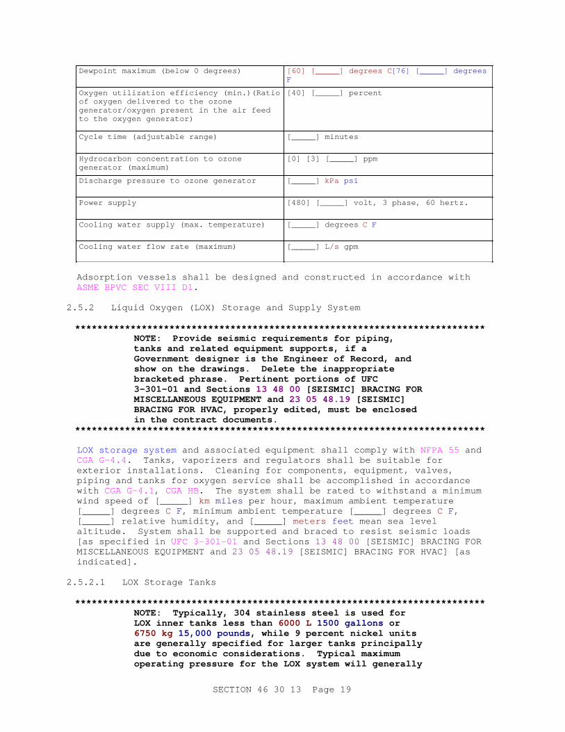
Dewpoint maximum (below 0 degrees) [60] [_____] degrees C [76] [_____] degrees F
Oxygen utilization efficiency (min.)(Ratio of oxygen delivered to the ozone generator/oxygen present in the air feed to the oxygen generator)
[40] [_____] percent
Cycle time (adjustable range) [_____] minutes
Hydrocarbon concentration to ozone generator (maximum)
[0] [3] [_____] ppm
Discharge pressure to ozone generator [_____] kPa psi
Power supply [480] [_____] volt, 3 phase, 60 hertz.
Cooling water supply (max. temperature) [_____] degrees C F
Cooling water flow rate (maximum) [_____] L/s gpm
Adsorption vessels shall be designed and constructed in accordance with ASME BPVC SEC VIII D1 .
2.5.2 Liquid Oxygen (LOX) Storage and Supply System
**************************************************************************NOTE: Pr ovi de sei smi c r equi r ement s f or pi pi ng, t anks and r el at ed equi pment suppor t s, i f a Gover nment desi gner i s t he Engi neer of Recor d, and show on t he dr awi ngs. Del et e t he i nappr opr i at e br acket ed phr ase. Per t i nent por t i ons of UFC 3- 301- 01 and Sect i ons 13 48 00 [ SEI SMI C] BRACI NG FOR MI SCELLANEOUS EQUI PMENT and 23 05 48. 19 [ SEI SMI C] BRACI NG FOR HVAC, pr oper l y edi t ed, must be encl osed i n t he cont r act document s.
**************************************************************************
LOX storage system and associated equipment shall comply with NFPA 55 and CGA G-4.4 . Tanks, vaporizers and regulators shall be suitable for exterior installations. Cleaning for components, equipment, valves, piping and tanks for oxygen service shall be accomplished in accordance with CGA G-4.1 , CGA HB. The system shall be rated to withstand a minimum wind speed of [_____] km miles per hour, maximum ambient temperature [_____] degrees C F , minimum ambient temperature [_____] degrees C F , [_____] relative humidity, and [_____] meters feet mean sea level altitude. System shall be supported and braced to resist seismic loads [as specified in UFC 3-301-01 and Sections 13 48 00 [SEISMIC] BRACING FOR MISCELLANEOUS EQUIPMENT and 23 05 48.19 [SEISMIC] BRACING FOR HVAC] [as indicated].
2.5.2.1 LOX Storage Tanks
**************************************************************************NOTE: Typi cal l y, 304 st ai nl ess st eel i s used f or LOX i nner t anks l ess t han 6000 L 1500 gal l ons or 6750 kg 15, 000 pounds, whi l e 9 per cent ni ckel uni t s ar e gener al l y speci f i ed f or l ar ger t anks pr i nci pal l y due t o economi c consi der at i ons. Typi cal maxi mum oper at i ng pr essur e f or t he LOX syst em wi l l gener al l y
SECTION 46 30 13 Page 19

be l ess t han 515 kPa 75 psi ; s i gni f i cant cost savi ngs can be achi eved by r educi ng t he t ank pr essur e r equi r ement s, but l ower pr essur e t anks may r equi r e a l onger l ead t i me t o pr ocur e s i nce t he 1. 2/ 1. 7 MPa 175/ 250 psi t anks ar e most commonl y provided.
**************************************************************************
Bulk LOX storage tanks shall be [_____] kg pound double walled vertical tanks constructed in conformance with [ ASME BPVC SEC VIII D1 ] [_____], rated for a maximum operating pressure of [1.2] [_____] MPa [175] [_____] psi and design temperature between minus 212 and plus 65 degrees C minus 350 and plus 150 degrees F , and seismic parameters defined in previous paragraph. The inner wall shall be constructed of [Grade 304 stainless steel] [9 percent nickel steel] [_____], the outer shell shall be constructed of carbon steel with a minimum outer shell thickness of [10] [_____] mm [0.375] [_____] inch . Annular area between the inner and outer walls shall be insulated to limit oxygen boil off rate to less than [0.25] [_____] percent of the tank capacity per day at the maximum ambient conditions. Piping shall be copper or 316 stainless steel. Fittings shall be bronze or 316 stainless steel.
2.5.2.2 Vaporizers
**************************************************************************NOTE: Vapor i zer s shoul d be desi gned f or t he ant i c i pat ed f l ow r at e t o t he ozone gener at or . I f vapor i zer s ar e over si zed, gas t emper at ur es wi l l r each out si de ambi ent t emper at ur es, r esul t i ng i n hi gher oxygen gas t emper at ur es dur i ng t he summer mont hs bei ng f ed t o t he ozone gener at or , r educi ng i t s ef f i c i ency. Nor mal oper at i ng pr essur e f or an ozone gener at or i s appr oxi mat el y 103 kPa 15 psi . Resul t i ng pr essur e at t he di f f user s i s appr oxi mat el y 103 kPa 15 psi l ess syst em l osses.
I n col d c l i mat es, heat er s may be r equi r ed t o war m t he oxygen gas f eed t o t he ozone gener at or . The act ual heat i ng r equi r ement s shoul d be coor di nat ed wi t h t he ozone gener at or manuf act ur er . I n cases wher e ambi ent t emper at ur es f al l bel ow f r eezi ng f or ext ended per i ods, suppl ement ar y heat i ng may be necessary.
LOX syst ems may r equi r e a smal l quant i t y of ni t r ogen gas be added t o t he f eed st r eam t o f aci l i t at e ozone gas f l ow t hr ough t he gener at or . Thi s may be accompl i shed by addi ng a smal l vol ume of dr i ed ambi ent ai r ( about 2 per cent ) .
**************************************************************************
Vaporization equipment shall consist of a minimum of [2] [3] ambient air vaporizers and [single] [double] regulator system complete with automatic switching and a manual bypass. Each vaporizer shall be rated for 100 percent capacity, under continuous operation at a [_____] cubic meters/second SCFM withdrawal rate and also capable of supplying a peak withdrawal rate of [_____] cubic meters/second scfm . The vaporization equipment shall be designed for an inlet pressure of [_____] kPa psi , and a maximum headloss between the tank and ozone generator of [_____] kPa psi .
SECTION 46 30 13 Page 20

The vaporizer extrusions shall have extra wide spacings between the individual extrusions with a minimum area per extrusion of [1.65] [_____] square meters/meter [5] [_____] sf/ft . [Heaters shall be provided to automatically warm the oxygen feed gas to the ozone generator when the oxygen feed temperature falls to less than [_____] degrees C F . Heaters shall be capable of warming the oxygen feed gas to a temperature range between [10 and 22] [_____] degrees C [50 and 72] [_____] degrees F ]. Each vaporizer shall operate for a minimum of [8] [_____] hours at the minimum ambient conditions and continuous withdrawal rate specified. The defrost cycle for each vaporizer shall be a maximum of [8] [_____] hours at the minimum ambient conditions and continuous withdrawal rate specified. Piping between the LOX tank and ozone generator shall be insulated as specified in Section 23 07 00 THERMAL INSULATION FOR MECHANICAL SYSTEMS.
2.5.2.3 Regulators
Regulators shall be factory tested with outlet pressure field adjustable over a downstream pressure range from [69 to 172] [_____] kPa [10 to 25] [_____] psi , from 0 to 100 percent of the specified oxygen flow rate. Regulators shall be rated at 1030 kPa 150 psi , and constructed of 316 stainless steel.
2.5.3 Ozone Generator Air Feed System
System equipment which processes ambient air directly as the ozone generator feed gas shall be provided by a single supplier, [be of the pressure swing type and] include an air compressor and receiver, aftercooler, [refrigerative dryer], vapor/liquid separator, [coalescing and] [particulate] filters, desiccant air dryer, particulate after filter, switching valves, pressure, temperature and moisture monitors, local controller and other equipment as required by the manufacturer to provide a complete and operational air preparation system . [The equipment shall be skid mounted.] Adsorption vessels shall be designed and constructed in accordance with ASME BPVC SEC VIII D1 . Adsorption material shall be [activated alumina] [_____]. The unit shall be completely wired requiring only an external connection for a single external power supply and remote monitoring [and control]. The air preparation system supplier shall be responsible for all work from the outside air inlet to the ozone generator inlet connection. The air preparation system shall be a continuous output system with the following characteristics based on 100 percent relative humidity and maximum ambient temperature of [_____] degrees C F :
Minimum dry air feed to ozonator [_____] cms scfm/m
Operating pressure at stated capacity [345] [_____] kPa [50] [_____] psi
Pressure drop through desiccant dryers (maximum)
[20] [_____] kPa [3] [_____] psi
Maximum air temperature to ozone generator
[30] [_____] degrees C [86] [_____] degrees F
Maximum dewpoint (below 0 degrees) [60] [_____] degrees C [76] [_____] degrees F
Maximum hydrocarbon concentration [0] [1] [_____] ppm
SECTION 46 30 13 Page 21

Discharge pressure to ozone generator (min)
[_____] kPa psi
Cycle time adjustable range [1 to 5] [_____] minutes
Power supply [480] [_____] volt, 3 phase, 60 hertz
2.5.4 Ozone Generator System
**************************************************************************NOTE: Del et e t hi s par agr aph i f an ozone gener at or i s not used. Hor i zont al t ube, medi um f r equency gener at or s ar e t he most common; however , s i nce t he st at e of t he ar t i s const ant l y changi ng, ver i f y t hat ot her t ypes of gener at or s ar e not avai l abl e or appr opr i at e f or t he par t i cul ar appl i cat i on.
Coor di nat e pr essur e r equi r ement s wi t h par agr aph Ozone Gener at or Ai r Feed Syst em. Typi cal pr essur e r anges r equi r ed f or ozone syst ems ar e dependant upon t he f i nal ozone out l et pr essur e, gener al l y bet ween 69 and 103 kPa 10 and 15 psi pl us l osses t hr ough t he equipment.
**************************************************************************
Ozone generation equipment shall be continuous duty water cooled, multi-tube glass or non-glass multitube dielectric [horizontal tube] [vertical tube] assemblies contained in a pressure vessel [with hinged gas-tight doors] with a rated design pressure of [_____] kPa psi . Each unit shall be provided with [medium] [high] frequency electrical power supply units including input and output transformers, power controller, frequency inverter, harmonic mitigation equipment (if required). The generator shall be provided with complete controls, [compatible with the central control unit,] instrumentation, panels, appurtenances and miscellaneous equipment required for a complete ozone generating system using [oxygen] [air]. All equipment, valves, piping, associated appurtenances shall be suitable for ozone in [oxygen] [air] service. Generator design requirements are as follows:
Capacity [_____] kg lbs /day
Gas flow rate to generator [_____] cms scfm
Outlet pressure + 5 percent) [_____] kPa psi
Ozone concentration [_____] percent
Generator vessel design pressure [_____] kPa psi
Ozone output concentration turn down [10:1] [_____]
Cooling water temperature rise at rated production capacity (maximum)
[3] [_____] degrees C [5] [_____] degrees F
Carrier gas rise across generator (max.) [30] [_____] degrees C [17] [_____] degrees F
SECTION 46 30 13 Page 22

Inlet hydrocarbon concentration (max) [0] [_____] ppm
Power supply [480] [_____] volt, 3 phase, 60 hertz
2.5.4.1 Ozone Generator Vessels
All ozone generator metal parts which come into contact with ozone or cooling water shall be constructed of Type 316L stainless steel. The vessel shall be designed to resist an internal pressure of 1.5 times the design pressure, including the tubes and shell. Over pressure protection based on worst case operating conditions shall be provided. The vessels shall be constructed in accordance with ASME BPVC SEC VIII D1 code. Viewing ports shall be provided to allow visual inspection of all internal dielectrics during operation.
2.5.4.2 Dielectric Tubes
Dielectric tubes shall be constructed to resist thermal shock and to evenly distribute the applied electrical charge over the entire dielectric surface without arcing. Dielectric tubes shall be formed from either glass or a non-glass material with a certified voltage breakage strength of 1.5 times the maximum possible operating voltage under maximum temperature and applied power conditions. Dielectric tubes shall be protected by fuses or functionally equivalent devices to prevent shorting dielectric tubes from damaging the shell and tube structure in the ozone generator.
2.5.5 Ozone Destruct System
**************************************************************************NOTE: Hi gh concent r at i ons of chl or i nat ed or gani cs may be l i ber at ed by syst ems whi ch use ozone i n ai r or oxygen. These chl or i nat ed or gani cs may " poi son" a cat al yst bed desi gned onl y f or ozone dest r uct i on. I f consi der abl e concent r at i ons of chl or i nat ed or gani cs ar e ant i c i pat ed ( gr eat er t han 1000 ppm) i n t he r eact or of f gas, a chl or i ne r esi st ant cat al yst shoul d be speci f i ed or a separ at e speci f i cat i on sect i on shoul d be used.
**************************************************************************
Ozone off gas destruction equipment shall be thermal assisted catalyst destruct type units suitable for moist ozone in [oxygen] [air] service. The catalyst containment unit, piping, ductwork, and other metallic components shall be constructed of 316 stainless steel. The units shall be capable of destroying contactor off gas generated by the ozone generators which feed the AOP reactors. The ozone destruction unit shall have the capability to function at a minimum turn down ratio of 20 to 1. Each off gas destruction unit shall be a skid mounted unit consisting of [a demister,] an electric resistance heater, catalyst trays and containment vessel [, and a centrifugal blower]. The destruction unit discharge duct shall be sloped away from the destruct unit to reduce the probability of catalyst fouling from condensation. Ducts carrying ozone laden off gas from the AOP reactors shall be sloped to a low point valved drain located upstream of the ozone destruct system. The ozone destruct system shall reduce the ozone concentration from the off gas flow to less than [0.10] [_____] ppm by volume of ozone from zero flow to the maximum
SECTION 46 30 13 Page 23

off gas flow rate. Normal operation is defined as [50] [_____] percent of the maximum off gas flow rate with an ozone concentration of [1.0] [_____] percent by weight. Ozone destruction equipment shall meet the following requirements:
Maximum pressure drop through catalyst at maximum flow rate
[_____] mm of mercury [_____] inches of water
Maximum pressure drop through heater at maximum flow rate
[_____] mm of mercury [_____] inches of water
Maximum off gas relative humidity [_____] percent
Max. temperature rise across heater [20] [_____] degrees C [35] [_____] degrees F
Catalyst chamber empty bed contact time [1.0] [_____] seconds
Max. ozone concentration into destruct unit
[1.0] [_____] percent by weight
Off gas flow rate (maximum) [_____] cubic m/s scfm
Maximum catalyst bed temperature [120] [_____] degrees C [250] [_____] degrees F
Off gas temperature to catalyst bed [15] [_____] degrees C [60] [_____] degrees F
Power supply [480] [_____] volts, [3] [_____] phase, 60 hertz
The catalyst shall be non-hazardous [manganese dioxide/copper oxide] [nickel] [_____] based material suitable for catalytic ozone destruction at the specified conditions. The catalyst containment unit shall be provided with a flanged and bolted top or hatch a minimum of 300 mm 12 inch in diameter to facilitate change out of the catalyst material when the catalyst is exhausted.
2.5.6 Hydrogen Peroxide System
**************************************************************************NOTE: Edi t Sect i on 46 30 00 WATER AND WASTEWATER CHEMI CAL FEED SYSTEMS t o pr ovi de on- of f , set poi nt , or pr opor t i onal cont r ol as appr opr i at e.
Hydr ogen per oxi de st or age syst em r equi r ement s shoul d be coor di nat ed wi t h suppl i er s t o ensur e mat er i al compat i bi l i t y . Fl oat i ng r oof manway ar ea shoul d equal 1 i n 2 per 400 L 100 gal l ons f or sol ut i ons l ess t han 52 per cent , and 2 i n 2 per 400 L 100 gallons f or sol ut i ons gr eat er t han 52 per cent . Pr ocess saf et y management r equi r ement s must be f ol l owed any t i me mor e t han 3375 kg 7500 pounds of H2O2 i s st or ed, or t he sol ut i on st r engt h i s gr eat er t han 52 per cent ; r ef er t o 29 CFR 1910. 119 f or information.
Hydr ogen per oxi de st or age t anks shoul d be l ocat ed out si de when possi bl e. Pol yet hyl ene shoul d not be used f or per oxi de concent r at i ons gr eat er t han 52 percent.
**************************************************************************
SECTION 46 30 13 Page 24

The hydrogen peroxide storage tank shall be constructed of cross linked polyethylene, 316 stainless steel, or 99.5 percent pure aluminum alloys designated in [ ASTM B209M] [ ASTM B209] as 1060, 5254, 5652. Hydrogen peroxide storage tanks shall be provided with secondary containment [as detailed on the drawings] [_____] with a minimum capacity equal to [110] [_____] percent of the maximum storage tank volume. Hydrogen peroxide storage tanks shall be equipped with [50] [_____] mm [2] [_____] inch female quick fill connection; [600] [_____] mm [24] [_____] inch hinged, weighted and gasketed manway cover; [50] [_____] mm [2] [_____] inch filtered breather vent; liquid level site tube; and [600] [_____] mm [24] [_____] inch free floating roof manway cover. All piping connections shall be flanged. Feed pumps shall conform to the requirements of Section 46 30 00 WATER AND WASTEWATER CHEMICAL FEED SYSTEMS.
2.5.7 Redox Potential Meter
The oxidation reduction meter shall be provided [where indicated on the drawings] [on the effluent line of each reactor]. Probe shall be easily removable without interrupting service. Probe materials shall be resistant to ozone as well hydrogen peroxide attack over a pH range of 2 to 12 and operating pressures of up to [_____] kPa psi and suitable for a temperature range from [0 to 100] [_____] degrees C [32 to 212] [_____] degrees F and suitable for the medium monitored. Probe shall transmit output to an ORP analyzer with digital output. The ORP analyzer shall transmit a [[4 to 20] [_____] mA signal proportional to the ORP] [direct digital reading] to the central control unit.
2.5.8 pH Probe
The pH probe shall be provided [where indicated on the drawings] [on the effluent line of each reactor]. Probe shall be easily removable without interrupting service. Probe materials shall be resistant to ozone as well hydrogen peroxide attack over a pH range of 0 to 14 and operating pressures of up to [_____] kPa psi and suitable for a temperature range from [0 to 100] [_____] degrees C [32 to 212] [_____] degrees F and suitable for the medium monitored. Probe shall transmit output to a pH analyzer with digital output. The pH analyzer shall transmit a [[4 to 20] [_____] mA signal proportional to the pH] [direct digital reading] to the central control unit.
2.5.9 Ozone Monitors
2.5.9.1 Vapor Phase
Separate ozone monitors shall be provided to monitor ozone in ambient air, [at the locations shown on the drawings,] determining the ozone levels downstream of the off gas ozone destruct system, [and the ozone concentration in the ozone generator discharge]. The ambient air monitoring unit intake shall be located [within 455 mm 18 inches above the treatment plant floor] [at the location shown on the drawings] [adjacent to the AOP process equipment]. The ambient air monitors shall be interlocked with the ozone generation system to initiate an alarm condition, and ozone generator shut down when readings exceed preset levels. Analyzers shall be [4 to 20 mA] [direct digital] output ultraviolet adsorption photometer type with built in pressure and temperature compensation. Ozone off gas monitor shall have a minimum of five separate ranges to monitor concentrations between [[0 to 15] [_____] percent,] [[0 to 99,000] [_____] ppm by volume]. Ambient air and off gas
SECTION 46 30 13 Page 25

destruct monitors shall have a minimum of five separate ranges to monitor concentrations between [0 to 10] [_____] ppm. Each monitor shall be provided with a builtin digital ozone concentration readout at the unit.
2.5.9.2 Liquid Phase
Liquid phase monitors shall be provided [where indicated on the drawings] [on the effluent line of the last reactor]. Sensor shall transmit output to an ozone analyzer with digital display and remote signal transmission to the central control unit. Probe shall transmit output to a liquid phase ozone analyzer with digital output. The liquid phase ozone analyzer shall transmit a [[4 to 20] [_____] mA signal proportional to the ozone concentration] [direct digital reading] to the central control unit.
2.5.10 Temperature Sensors
Temperature sensors shall be dual switch trip point independently adjustable type with a minimum accuracy of 0.5 percent of full scale. Thermal system shall be constructed of 316L stainless steel. Temperature range shall be from [0 to 100] [_____] degrees C [32 to 212] [_____] degrees F and suitable for the medium monitored. Sensor shall transmit output to an analyzer with digital output. The analyzer shall transmit a [[4 to 20] [_____] mA signal proportional to the temperature] [direct digital reading] to the central control unit.
2.5.11 Compressors
Air compressors shall conform to CAGI B19.1 . Air compressors shall be factory packaged [rotary screw] [centrifugal] [rotary] [reciprocating] type units. The air compressors shall be packaged in an enclosure with sound attenuating properties which allow a maximum noise level measurement of 75 dBA at the equipment enclosure. Air compressors shall be [water] [air] cooled and rated for continuous operation. Guards shall shield exposed moving parts. Compressor motors and starters shall conform with the requirements of Section 26 20 00 INTERIOR DISTRIBUTION SYSTEM. Air compressors shall have the manufacturer's name and address, together with trade name, and catalog number on a nameplate securely attached to the equipment. Any special maintenance instructions (required before startup or shutdown) shall be included in the Operations and Maintenance Manuals. Compressor equipment used for processing ambient air for the ozone generator feed gas shall include the air compressor, receiver with automatic condensate drain, intake air filter and silencer, after cooler, a high efficiency moisture separator, [refrigerative dryer], pressure, temperature and moisture monitors, local controller and other equipment as required by the manufacturer to provide a complete and operational oil free, dry compressed air system. Compressor receivers, air piping, valves and appurtenances unless otherwise specified, shall be in conformance with Section 22 00 00 PLUMBING, GENERAL PURPOSE. Dry contacts and 4 to 20 mA signals shall be provided in the control panel for remote monitoring.
Minimum capacity [_____] cms scfm
Operating pressure at stated capacity [345] [_____] kPa [50] [_____] psi
Maximum air temperature to PSA/VSA system
[30] [_____] degrees C [86] [_____] degrees F
SECTION 46 30 13 Page 26

Maximum dewpoint to PSA/VSA system (below 0 degrees)
[60] [_____] degrees C [76] [_____] degrees F
Maximum hydrocarbon concentration [0] [_____] ppm
Cycle time adjustable range [1 to 5] [_____] minutes
2.5.12 Blowers
Blowers shall conform to [Section 43 11 00 FANS/BLOWERS/PUMPS; OFF-GAS] [_____]. Dry contacts and 4 to 20 mA signals shall be provided in the control panel for remote monitoring.
2.5.13 Dew Point Monitor
The dew point transmitter shall be of a solid state design housed in a NEMA 4 enclosure as defined in NEMA 250, with an accuracy of plus or minus 3 degrees C over an operating ambient temperature range of minus 10 to plus 60 degrees C, over a dew point range of minus 110 to plus 10 degrees C. The transmitter shall receive the signal from the thin film aluminum metal oxide sensor, convert and send it as a [single 4 to 20 mA DC signal proportional to the dewpoint level] [direct digital reading] to the central control unit. Sensor shall transmit output to an analyzer with digital display.
2.5.14 Pressure Gauges
Water pressure gauges shall be glycerine filled units conforming to the requirements of ASME B40.100 .
2.5.15 Sampling Ports
Aqueous and gas phase sampling ports shall be provided [where indicated on the drawings] [upstream and downstream of each reactor vessel]. Sampling ports shall be provided at locations accessible to plant operators. Ports and associated piping shall be constructed of [6] [12] [_____] mm [1/4] [1/2] [_____] inch minimum diameter [PVDF] [316 stainless steel] [teflon] [_____] with [PVDF] [316 stainless steel] [_____] [NPT x hose] ball valves.
2.5.16 Gas Flow Meters
**************************************************************************NOTE: Numer ous met er s may be r equi r ed whi ch may necessi t at e a t abl e be i ncl uded i dent i f y i ng t he f l ow capaci t y f or each uni t .
**************************************************************************
Flow meters for ozone or oxygen applications shall have stainless steel body, tube, valves, floats, and knobs with glass windows. Flow meter shall be rated for a flow rate of [_____] cms scfm at a minimum pressure of [345] [_____] kPa [50] [_____] psi . Each flow meter shall be provided with a separate stainless steel valved connection for ease of maintenance. Each pipe penetration through the reactor wall serving a single ozone diffuser or bank of diffusers shall be equipped with a flow meter. The [air] [oxygen] feed stream to the ozone generator shall also be equipped with a flow meter. Each flow meter shall have an easily readable scale in cms scfm with a minimum of ten divisions from zero to 150 percent of the expected flow through the meter. Each meter shall be
SECTION 46 30 13 Page 27

provided with an analyzer which receives the signal from the flow meter transmitter, converts and sends it as a [single 4 to 20 mA DC signal proportional to the flow rate] [direct digital reading] to the central control unit. Sensor shall transmit output to an analyzer with digital display.
2.5.17 Level Monitoring
Pressure type level sensors, associated analyzers and transmitters shall be provided for each liquid process tank associated with the AOP system. Sensor element shall be removable for servicing or replacement without taking the tank out of service. As a minimum, the following tanks shall be equipped with level monitoring equipment: [reactor vessels,] [hydrogen peroxide storage and feed tanks,] [equalization tank,] [effluent storage and equalization tanks,] [_____]. Each level control element shall be of solid state design constructed of materials compatible with the liquid stored. Each controller shall be provided with an analyzer which receives the signal from the level sensor, converts and sends it as a [single 4 to 20 mA DC signal proportional to the liquid level] [direct digital reading] to the central control unit.
2.5.18 Reactor Vessel
**************************************************************************NOTE: Coor di nat e par agr aph Gas Fl ow Met er s r equi r ement s f or t he appl i cat i on; i ndi cat e penet r at i on r equi r ement s, i f a packi ng suppor t i s r equi r ed; v i ew por t s; s i t e gl asses; or mat er i al opt i ons t o st ai nl ess st eel r eact or s. Al so i ncl ude access r equi r ement s f or r emoval and mai nt enance of di f f user s. Coor di nat e uni que concr et e mat er i al ozone r esi st ance r equi r ement s wi t h Sect i on 03 30 00 CAST- I N- PLACE CONCRETE i f concr et e r eact or vessel s ar e used.
React or s f or per oxone syst ems, wher e ei t her t he ozone or hydr ogen per oxi de dose i s not expect ed t o exceed 25 ppm, may be const r uct ed of f i ber gl ass i f appr opr i at e r esi ns ar e used. Coor di nat e wi t h t ank suppl i er s r egar di ng speci f i cat i on r equi r ement s.
**************************************************************************
The reactor vessel shall be [circular] [rectangular], fabricated of [316L stainless steel] [concrete conforming to Section [ 03 30 00 CAST-IN-PLACE CONCRETE] [_____] provided with [_____] mm inch , [_____] kPa psi flanged connections.] Reactor vessels shall have a minimum water depth above the diffusers of [6] [_____] m [18] [_____] feet , with a minimum free board water depth above the liquid level of 600 mm 2 feet . [Reactor shall be designed to accommodate a vacuum of [25] [_____] mm [1] [_____] inch applied to the reactor headspace.] Welding shall be performed in accordance with AWS D1.1/D1.1M by welders certified to have passed qualification tests using procedures covered in AWS B2.1/B2.1M or ASME BPVC SEC IX . Reactors shall be equipped with openings required to ensure maintenance and installation/removal of the following equipment: liquid inlets and outlets, gas inlet supply and off gas collection points, sampling connections, [quartz sheath wipers], [UV lamps], [pH probe], [redox meter], [level switch], site glass liquid level indicator, and other connections as indicated or required. Reactor vessels shall be equipped with a minimum of [one] [_____] viewing port no smaller than
SECTION 46 30 13 Page 28

[0.5] [_____] m [1.5] [_____] feet located [0.7] [_____] m [2] [_____] feet minimum above the bottom of the reactor. The viewing port shall be covered with clear plastic material not susceptible to ozone degradation, with a minimum thickness of [10] [_____] mm [3/8] [_____] inch .
2.6 ELECTRICAL
Electrical products shall be in accordance with Section 26 20 00 INTERIOR DISTRIBUTION SYSTEM. Reactor vessels containing ultraviolet lamps shall be independently grounded.
2.6.1 Motors
Motors, all motor starters, and any control or signal wiring required for the operation of the specified equipment shall be provided and installed under this section in accordance with Section 26 20 00 INTERIOR DISTRIBUTION SYSTEM unless otherwise specified herein, in other sections, or indicated on the drawings.
2.6.2 Local Controls and Panels
Manual or automatic controls, protective or signal devices required for the operation specified, and any control wiring required for controls and devices, shall be provided. Enclosures for local power and control panels shall conform to NEMA ICS 6 .
2.6.3 Ultraviolet Equipment Electrical Requirements
a. A separate prewired power panel shall be provided for each module.
b. Ground fault detection or independent ground shall be standard with the UV lamp equipment.
c. Control and monitoring components shall be housed in NEMA enclosures. Internal components shall be sealed from the environment. System electronics to be used in an interior environment shall be housed in enclosures conforming to NEMA 250 TYPE 12. System electronics to be used in an exterior and corrosive environment, as defined in NEMA 250, shall be housed in enclosures conforming to NEMA 250 TYPE 4X.
d. Sufficient cooling shall be provided to the medium and high temperature UV bulbs as well as associated ballasts to prevent overheating.
e. Wiring and electrical connections shall be protected against moisture and corrosive gases to prevent electrical shorts or failure. Electrical installation and materials shall conform to NFPA 70 . The unit shall be completely wired requiring only an external connection for a single external power supply and remote monitoring and control.
f. Interconnecting, multiconductor, unshielded cables shall be suitable for outdoor installation. Insulation shall be thermoplastic rubber with an operating range of minus 60 to 125 degrees C minus 75 to 260 degrees F with low temperature flexibility and flame retardants. UV stabilized jacketing shall be resistant to oils, chemicals, fuels, solvents, and to mechanical abuse and abrasion. Cable shall be supplied by the equipment manufacturer and shall be of sufficient length and number for a complete system.
SECTION 46 30 13 Page 29
g. Cableways provided shall be stainless steel, 1.98 or 1.59 mm 14 or 16 gauge thick.
2.7 AOP CONTROL SYSTEM
**************************************************************************NOTE: Del et e i t ems wi t hi n t hi s par agr aph t hat do not appl y. Not al l UV syst ems ( especi al l y t hose wi t h l ow i nt ensi t y l amps) have l i ght i nt ensi t y moni t or s; ver i f y desi gn r equi r ement s f or t ype or need of l amps. Hydr ogen per oxi de moni t or i ng on al l but ver y l ar ge pl ant s ( l ar ger t han5. 7 ML/ day 1. 5 MGD) wi l l consi st of t ank l evel r eadi ngs and an i ndi cat i on t hat t he chemi cal f eed pump i s wor ki ng. Coor di nat e wi t h par agr aph Al ar ms and I nt er l ocks i f separ at e audi bl e or v i sual al ar ms beyond t he cont r ol syst em speci f i ed ar e r equi r ed, and t hei r l ocat i on.
I f an aut odi al er i s r equi r ed, r ef er ence t he cont r ol s and i nst r ument at i on sect i on of t he speci f i cat i on; or i f none i s i ncl uded and an aut odi al er i s r equi r ed, i ncl ude t hose r equi r ement s i n t hi s par agr aph.
**************************************************************************
Equipment shall be locally controlled and shall be capable of receiving standard digital or analog control signals from the plant central control system. Status and adjustments to the equipment shall be provided [locally] [and] [from the plant central control system]. Instruments shall be provided with mounting hardware as appropriate. Transmitters with digital outputs shall be accurate to within [_____] percent. All equipment shall be designed for operation on a 120 volts 60 hertz electrical input. Controls shall be provided to remotely monitor [and adjust] [hydrogen peroxide delivery rate,] [oxygen] [air] [and ozone output,] [_____] [individual lamp failure,] [power on and off status for each lamp [ballast]] [ultraviolet lamp intensity]. [Each lamp shall be provided with a nonresettable elapsed time meter with ability to record operable hours from 0 to 99,999].
2.7.1 Ozonation Control System
The ozonation control system shall be interfaced with the plant central control system. Changes to the ozone generator equipment operating conditions shall be accomplished locally or from the master control panel. The power, control and instrumentation system provided shall be as specified or as recommended by the ozone generator manufacturer for safe operation and supervision of the ozone generator and related gas feed equipment. Schematics and interconnecting wiring diagrams shall be provided for power, control, and instrumentation circuits. Control power transformers, relays, adjustable timers, auxiliary contacts, switches, or additional equipment to interconnect the generator to other auxiliary equipment and master control panel, and control circuits as shown on schematic or instrument control drawings shall be provided. An emergency stop button shall be provided at the local generator control panel. The ozone generator shall be protected from power surges, and variations in power supplied to the equipment.
2.7.2 Hydrogen Peroxide Feed
**************************************************************************
SECTION 46 30 13 Page 30
NOTE: Hydr ogen per oxi de met er i ng r at e i s gener al l y done manual l y wi t h an i nt er l ock t o shut t he syst em down when a f l ow swi t ch or ot her i nt er l ock at t he AOP mast er cont r ol i ndi cat es a f l ow i nt er r upt i on. I f a var i abl e f l ow r at e i s ant i c i pat ed, al t hough r ar el y used, t he hydr ogen per oxi de f eed r at e can be t i ed t o t he i nf l uent met er or AOP mast er cont r ol . Coor di nat e oper at i on wi t h Sect i on 46 30 00 WATER AND WASTEWATER CHEMI CAL FEED SYSTEMS.
**************************************************************************
Hydrogen peroxide feed pump and control shall conform to the requirements of Section 46 30 00 WATER AND WASTEWATER CHEMICAL FEED SYSTEMS.
2.7.3 Alarms and Interlocks
**************************************************************************NOTE: Del et e i t ems i n t hi s par agr aph t hat ar e not required.
Coor di nat e t hi s par agr aph wi t h pr ocess and i nst r ument at i on di agr ams ( PI Ds) and ot her speci f i cat i on sect i ons. Met er i ng accur acy f or hydr ogen per oxi de i s gener al l y done manual l y. I ndi cat e i f separ at e audi bl e or v i sual al ar ms beyond t he AOP mast er cont r ol syst em ar e r equi r ed, and t hei r l ocat i on.
**************************************************************************
Alarms and interlocks shall be provided to ensure proper operation of the advanced oxidation equipment, and its sequenced shutdown based on potentially unsafe or improper conditions that may exist. The following paragraphs list alarms that (as a minimum) shall be monitored at the central control point, or that will initiate shutdown of the appropriate advanced oxidation equipment components.
2.7.3.1 AOP System
Failure of major equipment components such as lamps, ballasts, or safety interlocks shall initiate system, followed by plant shutdown, if not acknowledged.
a. AOP system alarms and control interlocks shall be provided for the following items:
(1) Lamp failure(2) Ballast failure(3) Safety interlocks for open door on reactor vessel or panel(4) High water temperature in AOP reactor vessel(5) Low water flow to the reactor vessel(6) Sleeve wiper failure(7) High pressure in reactor vessel headspace(8) [_____].
b. Submit the following data for the AOP System
(1) Manufacturer's descriptive and technical literature; performance charts and curves, catalog cuts for specified equipment including: instrumentation and controls; capacities and pressure drop; model
SECTION 46 30 13 Page 31

number; and installation instructions.
(2) Materials of construction; inlet and outlet pipe sizes; power demand requirements; and ozone generator cooling water flow rate.
(3) Spare parts data for each piece of equipment, current unit prices and source of supply.
(4) Manufacturer's descriptive and technical literature; performance charts and curves, catalog cuts for specified equipment including: instrumentation and controls; capacities and pressure drop; model number; and installation instructions.
(5) Materials of construction; inlet and outlet pipe sizes; power demand requirements; and ozone generator cooling water flow rate.
(6) Spare parts data for each piece of equipment, current unit prices and source of supply.
(7) Manufacturer's certificates stating that the equipment meets the specified requirements, and has been installed in accordance with the equipment manufacturer's requirements.
2.7.3.2 Metering Pump
Pump failure shall initiate system, followed by plant shutdown, if not acknowledged. Metering Pump alarms and control interlocks shall be provided for the following items:
a. Hydrogen peroxide feedb. Catalyst feedc. Pump failured. [_____].
2.7.3.3 Hydrogen Peroxide Tank
Hydrogen peroxide tank [alarms] [and control interlocks] shall be provided for the following items:
a. High liquid levelb. Low liquid levelc. Low low liquid leveld. High temperaturee. High pressuref. [_____].
2.7.3.4 Ozone System
Ozone system alarms and control interlocks shall be provided for the following items:
a. High dew point in gas feed to ozone generatorb. Over current to the power supply unit (PSU)c. Over voltage to the PSU, rectifier, and inverterd. Over frequency protectione. High temperature shut downf. High inlet gas temperatureg. High inlet cooling water temperatureh. High gas pressure to the generator
SECTION 46 30 13 Page 32

i. Insufficient gas flow to the generatorj. High outlet ozone gas temperaturek. High moisture level in control cabinetl. [_____].
Major equipment component failure such as over current, over voltage, over frequency, high cooling water temperature or other condition that could damage the equipment or result in effluent non-compliance shall initiate system, followed by plant shutdown, if not acknowledged.
2.7.3.5 Gas Feed System
Gas feed system alarms and control interlocks shall be provided for the following items:
a. High pressure across gas filtersb. High temperature in gas desiccant dryerc. High pressure downstream of reducing valvesd. Air preparation system failuree. Ozone monitor failuref. [_____].
Major equipment component failure, such as high cooling water temperature, air preparation failure, or other condition that could damage the air feed or ozone equipment, or result in effluent non-compliance shall initiate system, followed by plant shutdown, if not acknowledged.
2.7.3.6 Ozone Destruct System
Ozone destruct system alarms and control interlocks shall be provided for the following items:
a. High ozone in ambient air spaceb. High gas flow rate to destruct unitc. Low temperature in ozone destruct unitd. High ozone in destruct unit exhaust gase. Ozone destruct system failuref. High ozone concentration in off gasg. Destruct system failureh. [_____].
Health and safety ambient ozone level non-compliance shall initiate ozone system alarm and shutdown, followed by overall plant shutdown, if alarm is not acknowledged (high ambient ozone levels will not shutdown the ozone destruct system concurrently with other processes).
2.7.3.7 Cooling Water System
Cooling water system alarms and control interlocks shall be provided for the following items:
a. Cooling systems failureb. High water temperaturec. No/low cooling water flowd. Pump failuree. [_____].
Major equipment component failure such as no/low cooling water flow, pump failure or other condition that could damage the gas feed, ozone equipment
SECTION 46 30 13 Page 33

or result in effluent non-compliance shall initiate ozone generator, followed by plant system shutdown, if not acknowledged.
2.7.3.8 Metering Accuracy
Metering accuracy alarms and control interlocks shall be provided for the following items: Ozone and Hydrogen Peroxide
2.7.3.9 Ground Fault
A ground fault protection alarm shall be provided.
2.8 SPECIAL EQUIPMENT AND TOOLS
Provide one set of special tools, calibration devices, and instruments required for operation, calibration, and maintenance of the equipment. Provide a tube cleaning rack or racks with adequate capacity to hold [50] [100] percent of the dielectric tubes from the ozone generator being serviced. Each rack shall be equipped with locking casters to allow the rack to be easily moved between the ozone generator and the location where the dielectric tube cleaning will occur. Each dielectric shall be provided with an individual padded holder.
PART 3 EXECUTION
3.1 EXAMINATION
After becoming familiar with all details of the work, verify all dimensions in the field, and advise the Contracting Officer of any discrepancy before performing the work. Compare the limits of work for the equipment supplied to field conditions to ensure the limits previously identified for piping, electrical and control interfaces meet the actual physical requirements at the facility. Bring any discrepancies to the attention of the Contracting Officer for correction.
3.2 PREPARATION
**************************************************************************NOTE: Thi s par agr aph cover s act i ons r equi r ed t o physi cal l y pr epar e t he sur f ace, ar ea, or s i t e t o i ncor por at e t he speci f i ed pr i mar y pr oduct s.
**************************************************************************
Provide the reactor vessel, [ozone and feed gas equipment,] [hydrogen peroxide storage and feed system,] [electrical support equipment,] and [_____] with an equipment pad isolated from the floor slab [as detailed on the drawings] [adequate to properly support the equipment]. Reinforced concrete shall be designed and installed in accordance with Section 03 30 00 CAST-IN-PLACE CONCRETE. Prior to placing ozone piping, or other equipment, into service it shall be cleaned by one of the methods specified in CGA G-4.1 . Piping and equipment used to store or feed hydrogen peroxide shall be passivated in accordance with the hydrogen peroxide supplier's requirements.
3.3 EQUIPMENT INSTALLATION
Perform the equipment installation as indicated on the drawings, shop drawings, manufacturer's instructions and recommendations. Piping, valves, fittings, and appurtenances shall be installed in accordance with
SECTION 46 30 13 Page 34

the manufacturers recommendations, as specified in Section 22 00 00 PLUMBING, GENERAL PURPOSE, or as otherwise indicated. All valves, fittings, meters and other appurtenances shall be given unique identification numbers corresponding to those used in operation and maintenance manuals, and in AOP submittals prepared. Identification numbers shall be placed on brass identification tags and securely fastened to all valves, fittings, meters and other appurtenances. Tags shall not be less than 38 mm 1-1/2 inches in diameter with depressed black figures 13 mm 1/2 inch high. Piping for wet ozone service shall be PVDF, stainless steel, or PTFE. Piping for dry ozone service shall be PVDF, stainless steel, or PTFE. Oxygen Piping shall be copper or stainless steel. Hydrogen peroxide piping shall be stainless steel, PTFE or PVDF. Oxygen piping shall [be insulated in accordance with Section 23 07 00 THERMAL INSULATION FOR MECHANICAL SYSTEMS] [not be insulated].
3.4 ELECTRICAL WORK
Perform electrical work in accordance with the drawings and applicable requirements of Section 26 20 00 INTERIOR DISTRIBUTION SYSTEM. Equipment shall be appropriate for continuous duty, and installation in a dusty, humid and corrosive environment. Electrical equipment and wiring shall comply with NFPA 70 .
3.5 TOOLS
Provide tools to the Contracting Officer prior to the onsite training identified in paragraph FIELD TRAINING.
3.6 PAINTING/CORROSION PROTECTION
All ferrous surfaces shall be coated or painted. Color shall be as indicated on the paint schedule or as otherwise approved. Factory painted items shall be touched up as needed. Factory painted items requiring touch up in the field shall be thoroughly cleaned of all foreign material, primed and top coated with the manufacturer's standard factory finish in accordance with the manufacturer's recommendations, including dry finish thickness. Equipment which did not receive a factory finish shall be painted in accordance with the requirements indicated in Section 09 90 00PAINTS AND COATINGS. Painting corrosion resistant metals such as brass, bronze, aluminum, copper, galvanized steel and stainless steel is not required unless otherwise specified.
3.7 CHEMICALS
**************************************************************************NOTE: Coor di nat e t hese r equi r ement s wi t h ot her speci f i cat i ons whi ch may addr ess ext ended oper at i on and mai nt enance occur r i ng i n some HTRW Pr oj ect s. I f ot her suppl i es such as cat al yst s ar e r equi r ed, i ncl ude t hat i nf or mat i on as wel l .
**************************************************************************
Provide the chemicals needed to do all the operational and start up testing, and completely refill the [oxygen], [hydrogen peroxide], [catalyst], [_____] tanks at the time of contract completion.
3.8 WELDING
**************************************************************************
SECTION 46 30 13 Page 35
NOTE: Use second set of br acket s when cr i t i cal pi pe wel di ng i s r equi r ed.
**************************************************************************
[Piping shall be welded in accordance with qualified procedures using performance qualified welders and welding operators. Procedures and welders shall be qualified in accordance with ASME BPVC SEC IX . Welding procedures qualified by others, and welders and welding operators qualified by another employer may be accepted as permitted by ASME B31.1 . The Contracting Officer shall be notified 24 hours in advance of tests. Structural members shall be welded in accordance with Section 05 05 23.16 STRUCTURAL WELDING.] [Welding and nondestructive testing procedures for piping shall be as specified in Section 40 05 13.96 WELDING PROCESS PIPING.]
3.9 SAMPLING AND ANALYSIS
Perform sampling, analysis, and sample turn around time to demonstrate system performance and effluent compliance. Submit a commissioning/demonstration plan for approval to ensure the equipment meets the standards indicated. Coordinate this plan with other plans and unit operations to ensure they do not conflict and the AOP system is ready for testing. Coordinate and obtain regulatory approvals prior to notifying the contracting officer that the equipment is ready for testing.
3.9.1 Plan Details
The plan shall include a detailed description of proposed sampling and analysis required to document system performance. A plan detailing the sampling locations, frequency, analytical protocols, and duration which will ensure the equipment complies with the standards indicated. Submit the plan to the Contracting Officer [_____] [30] days prior to equipment start up. Coordinate work within this section with other sections to ensure upstream and downstream unit processes are complete and operational prior to startup/commissioning the AOP unit.
3.9.2 Plan Calculations
Include the following calculations in the commissioning/demonstration plan.
a. Headloss calculations through the process units at the design flow rate, including headloss calculations for associated compressed air and pumping systems.
b. Oxidant demand and subsequent AOP unit sizing.
c. Electrical usage rate.
d. Removal performance and material mass balance.
e. Chemical feed requirements and equipment sizing.
f. Diffuser system layout, mass transfer calculations.
3.9.3 Chemical Sampling
The chemical parameters identified in paragraph PERFORMANCE REQUIREMENTS [and ambient and ozone off-gas destruction concentrations] shall be sampled [daily] [_____], monitored [at the locations identified on the
SECTION 46 30 13 Page 36
drawings] [at the locations indicated in the startup/commissioning plan] for [7] [_____] days of continuous 24 hour operation, using analyses with detection limits one order of magnitude lower then the levels indicated in paragraph PERFORMANCE REQUIREMENTS.
3.10 POSTING FRAMED INSTRUCTIONS
Post framed instructions containing wiring and control diagrams, under glass or in laminated plastic, adjacent to the equipment or where otherwise directed before acceptance testing of the system. Condensed operating instructions, prepared in typed form, shall be framed as specified above and posted beside the diagrams. The framed instructions shall be posted before acceptance testing of the systems.
3.11 FIELD TESTS AND INSPECTIONS
**************************************************************************NOTE: These t est s ar e r equi r ed f or i nst al l ed or compl et ed wor k; t hey ar e di f f er ent and separ at e f r om t hose r equi r ed f or mat er i al s and pr oduct s pr i or t o i nst al l at i on or appl i cat i on. Del et e t est s not appl i cabl e or r equi r ed.
Pr ovi de i n t hi s sect i on a r ef er ence t o t he pl ant commi ssi oni ng or st ar t - up speci f i cat i on whi ch i ncl udes t he pr ocesses i n t he t r eat ment f aci l i t y .
**************************************************************************
Accessories such as the [UV equipment,] [ozone generator,] [compressor,] [ozone generator gas feed equipment,] and [_____] shall be factory tested prior to shipment to the job site.
3.11.1 AOP Reactor Vessel
The AOP reactor vessel and attached appurtenances shall be assembled at the factory and an operational test of all components accomplished prior to shipment. Certification that the equipment and components assembled at the factory are operational and meet the specification requirements shall be provided to the Contracting Officer a minimum of [10] [_____] calendar days prior to shipment. Components not assembled at the factory shall be subject to the same tests and inspections prior to onsite leak testing using potable water. Following installation at the project site, and prior to leak testing, the AOP system shall be retested to ensure the equipment and auxiliary components act as a complete and operational system. This shall include operation of all valves, pumps, blowers, analyzers, alarms, meters, interlocks, monitors, level and pump controls, sensors, switches, off gas destruct equipment and all other equipment associated with the AOP system. Testing shall be completed prior to leak testing and written notification provided to the Contracting Officer stating the equipment is working in accordance with the contract documents and manufacturer's recommendations prior to the commencement of leak testing.
3.11.2 Diffuser or Injector System
The entire gas piping system shall be pressure tested with dry air or oxygen at a minimum of [two] [_____] times the normal design pressure for a minimum of 60 minutes and such additional time as required for the Contractor to inspect the piping system for leaks. All leaks shall be
SECTION 46 30 13 Page 37

repaired and the system shall be retested until no leakage is detected. Ozone shall not be introduced into the system until all leaks have been identified, repaired, and the system retested. [Diffusers] [Injectors] shall be installed in accordance with the suppliers recommendations. After installation, the [diffusers] [injectors] shall be covered with clear water to a depth of approximately [1] [_____] m [3] [_____] feet . Dry air or oxygen shall be released through the [diffusers] [injectors] and the system shall be inspected for uniform air or oxygen distribution throughout the reactors. Following the initial testing at [1] [_____] m [3] [_____] feet , the distribution testing shall be repeated at a water depth of [3] [_____] m [9] [_____] feet to ensure bubble distribution is adequate throughout the reactor. [Diffuser] [Injector] replacement or repositioning shall be accomplished as required to maintain uniform air distribution throughout the reactor. If after repositioning, air distribution throughout the reactor lacks uniformity, additional redistributors or deflectors shall be installed in the reactor as recommended by the [diffuser] [injector] supplier to accomplish uniform flow distribution throughout the reactor.
3.11.3 Leak Testing
Leak testing shall be accomplished at the factory to verify the integrity of the reactor vessels and associated gas and liquid piping. The factory leak test shall be accomplished on the reactor vessel and appurtenances following assembly at the factory. Onsite hydrostatic leak testing shall include all piping between the upstream and downstream processes, and be accomplished using potable water at a pressure 1.5 times the working pressure, or 350 kPa 50 psi unless otherwise approved by the Contracting Officer. The reactor vessel and appurtenances shall be isolated from the connecting piping and retested for leaks using potable water following assembly at the site. The ozone generator gas connections shall be tested with dry air or oxygen at the maximum pressure allowed by the manufacturer, or as identified in the previous paragraph. Any gas or liquid leaks identified during the aforementioned testing shall be repaired and the system shall be retested until the systems are free of leaks.
3.11.4 Control Panel
A local control panel functionality test shall be performed and approved by the Contracting Officer prior to commencement of leak testing or testing using oxidizers. The central control testing shall be accomplished prior to overall plant startup.
3.11.5 Ozone Generation System
**************************************************************************NOTE: The i nst al l er or manuf act ur er shoul d demonst r at e t he oper at i on and ef f i c i ency of t he equi pment . Power consumpt i on f or ozone gener at i on shoul d be l ess t han 10 kWhr per 0. 5 kg pound of ozone gener at ed assumi ng a PSA oxygen f eed syst em i s used t o gener at e a 10 per cent ozone f eed; ver i f y t hi s wi t h mul t i pl e equi pment suppl i er s based on t he speci f i c ozone appl i cat i on pr essur es t o be used, gas f eed, and appl i ed ozone concent r at i on.
**************************************************************************
The ozone generation system shall be tested to ensure that the actual
SECTION 46 30 13 Page 38

ozone production, power usage, or water consumption rates meet recommended requirements. Power usage shall be measured after achieving steady state conditions as determined by the ozone generator supplier. Power usage shall be measured at the central motor control center or at each individual component including the [air dryer,] [refrigerant driers,] [desiccant driers,] [oxygen generator,] ozone generator, cooling water pumps, and master control panel. Power usage shall be within [5] [_____] percent of [_____] kWh per kg pound of ozone generated at 100 percent of rated capacity. Cooling water supply shall also be measured. Cooling water consumption rate shall not exceed [_____] L/s gpm at the parameters listed in paragraph Ozone Generator System by more than [5] [_____] percent. If the equipment does not meet the specified consumption rates, make the necessary system revisions to meet the rates specified at no additional cost to the Government. Power usage shall also be evaluated at 25, 50, and 75 percent of the design production rate.
3.12 MANUFACTURER'S SERVICES
**************************************************************************NOTE: Use t hi s par agr aph when manuf act ur er s ar e t o pr ovi de f i el d qual i t y cont r ol wi t h onsi t e per sonnel f or i nst r uct i on/ super vi s i on of t he i nst al l at i on or appl i cat i on of t hei r pr oduct s, or f or st ar t up or demonstration.
Thi s par agr aph cover s r equi r ement s of t he i nst al l er or manuf act ur er t o demonst r at e t he oper at i on and mai nt enance of equi pment t o t he owner ' s per sonnel .
**************************************************************************
Provide a manufacturer qualified service representative, experienced in the installation, adjustment, operation and maintenance of the equipment specified, for a minimum of [3] [_____] days to supervise the installation, adjustment, testing, and to provide instruction in the operation, and maintenance of the equipment. If major components from multiple suppliers are provided, such as an [ozone generator] [air preparation system] [oxygen preparation system] [ozone destruct system] [_____], each supplier shall be required to visit the site a minimum of [1] [_____] times during equipment installation or startup. During the startup and [one] [_____] years operating period, the major equipment suppliers shall be required to be onsite [2] [_____] times to verify that the equipment is installed and operates properly, and to provide trouble shooting and technical assistance.
3.13 FIELD TRAINING
Provide a field training course for designated operating and maintenance staff members. The training shall include operation of individual components as well as the integrated system, maintenance needs and procedures, instrument calibration, safety issues and emergency procedures, control and alarm features, troubleshooting equipment and control problems, and laboratory analytical procedures. Training shall be provided during normal working time and shall start after the system is functionally complete but prior to performance testing. Field training shall cover all of the items contained in the operating and maintenance manuals. Each major equipment vendor including, but not limited to, the ozone generator, ozone destruct system, ozone monitoring system, and gas feed system shall be required to provide two [8] [_____] hour periods of classroom and hands-on operating instruction to the individuals selected
SECTION 46 30 13 Page 39

by the Contracting Officer. The first period shall be at system startup and the second [as defined by the Contracting Officer] [at the end of the Contractor's operating contract, prior to turning over to the long term facility operator]. Upon completion, submit certificates indicating the designated personnel have received training specified and have successfully operated the installed AOP equipment.
3.14 MAINTENANCE
3.14.1 Extra Materials
**************************************************************************NOTE: Del et e i nappl i cabl e por t i ons of t hese par agr aphs. Coor di nat e t hi s sect i on wi t h ot her sect i ons of t he speci f i cat i ons t o ensur e t her e ar e not conf l i c t s r egar di ng suppl y i ng consumabl es. Ver i f y t he dur at i on of t he i ni t i al oper at i ng per i od, whi ch i s gener al l y 1 year .
**************************************************************************
Furnish the initial supplies to fill the vessels, as well as all consumables during the startup, prove out, and initial operation period. At the time the Contractor turns the plant over to the long term Operation and Maintenance Contractor, the vessels storing consumables such as LOX, hydrogen peroxide [and] [_____] shall be refilled within [two] [five] days prior to the plant turn over.
3.14.1.1 Lamps
Provide a complete set of lamps reserved for change out by the equipment supplier following the one year warranty period. This extra set of lamps shall be delivered to the treatment facility 60 days prior to the end of the one year warranty period and installed by the Contractor. Lamp replacement during the one year warranty period shall be provided by the supplier, as needed by the Contractor.
3.14.1.2 Spare Parts
The supplier shall provide, in addition to the lamps specified above, a minimum of ten percent of each of the following items, or a minimum of two, whichever is greater:
a. Lamp ballasts
b. Quartz sleeves
c. End seals
d. Socket connectors
e. O-rings
f. Quartz sleeve cleaners
g. Diffusers
h. Rotometers
i. Generator dielectrics
SECTION 46 30 13 Page 40

j. Generator dielectric fuses
k. pH probe element
l. ORP probe element
3.14.2 Maintenance Service
**************************************************************************NOTE: Del et e t hi s par agr aph i f UV l amps ar e not used. The desi gner may want t o pr ovi de addi t i onal i nf or mat i on r egar di ng l amp change out i f t he syst em i s l i mi t ed t o a cer t ai n l amp t ype. Medi um pr essur e l amps have an appr oxi mat e l i f e of 3 t o 4000 hour s, whi l e l ow pr essur e l amps have an appr oxi mat e l i f e of 7 t o 10000 hour s; cer t ai n pr opr i et ar y, hi gh i nt ensi t y l amps may have a l i f e l ess t han 2000 hour s.
**************************************************************************
Changing out lamps, ballasts, and quartz tube wipers, at the frequency recommended by the manufacturer during the one year warranty period or as otherwise required, shall be the Contractor's responsibility. Lamps and ballasts supplied as specified below, shall be provided in addition to the complete set supplied for installation (following the warranty period) and those installed as needed during the warranty period. The ozone generator dielectrics shall be cleaned in accordance with the manufacturer's recommendations immediately prior to the conclusion of the Contractor's operating period; or after one year, if greater than one year after startup, and at the conclusion of the Contractor's operating period.
3.14.3 Operating Instructions
Submit [six] [_____] complete copies of operating instructions outlining the step-by-step procedures required for system start-up, operation and shutdown, routine maintenance, potential breakdowns and repairs, and troubleshooting. The instructions shall include drawings and schematics of the system as installed. The instructions shall include the manufacturer's name, model number, service manual parts list and brief description of all equipment and their basic operating features. The instructions shall include, but not be limited to, the following:
a. System layout showing piping, valves and controls, process flow diagrams, piping and instrumentation diagrams with all valves, meters, and similar units identified.
b. Approved wiring and control diagrams prepared in accordance with ANSI/ISA 5.1 including a drawing index, legend and symbols list, and abbreviations and identifiers.
c. A control sequence describing startup, how to make adjustments to the equipment during operation, standard and emergency shutdown procedures.
d. Operating and maintenance instructions for each piece of equipment, including lubrication instructions and other periodic maintenance and inspection information as well as trouble shooting guides.
e. Manufacturer's bulletins, cut sheets and descriptive data, parts lists, and recommended spare parts, and sources of supply for all
SECTION 46 30 13 Page 41

major pieces of equipment.
-- End of Section --
SECTION 46 30 13 Page 42
Related Documents


![UFGS - [01321N.PRN]](https://static.cupdf.com/doc/110x72/616a497811a7b741a350dac5/ufgs-.jpg)

