42C15SE0886 NAMEIGOSOQI? LIZAR 010 REPORT ON COMBINED HELICOPTER-BORNE MAGNETIC, ELECTROMAGNETIC, AND VLF-EM SURVEY ON NAMEIGOS RIVER CLAIMS UEC for PRYME ENERGY RESOURCES by AERODAT LIMITED July 1983

Welcome message from author
This document is posted to help you gain knowledge. Please leave a comment to let me know what you think about it! Share it to your friends and learn new things together.
Transcript
42C15SE0886 NAMEIGOSOQI? LIZAR 010
REPORT ON
COMBINED HELICOPTER-BORNE
MAGNETIC, ELECTROMAGNETIC,
AND VLF-EM SURVEY
ON
NAMEIGOS RIVER CLAIMS
UEC
for
PRYME ENERGY RESOURCES
by
AERODAT LIMITED
July 1983
01®C
TABLE OF CONTENTS
Page No,
1. INTRODUCTION 1-1
2. SURVEY AREA/CLAIM NUMBERS AND LOCATIONS 2-1
3. AIRCRAFT EQUIPMENT 3-1
3.1 Aircraft 3-1
3.2 Equipment 3-1
3.2.1 Electromagnetic System 3-1
3.2.2 VLF-EM 3-1
3.2.3 Magnetometer 3-2
3.2.4 Magnetic Base Station 3-2
3.2.5 Radar Altimeter 3-2
3.2.6 Tracking Camera 3-3
3.2.7 Analog Recorder 3-3
3.2.8 Digital Recorder 3-4
4. DATA PRESENTATION 4-1
4.1 Base Map and Flight Path Recovery 4-1
4.2 Electromagnetic Profile Maps 4-2
4.3 Magnetic Contour Maps 4-4
4.4 VLF-EM Contour Maps 4-5
4.5 Electromagnetic Survey Conductor 4-6 Symbolization
4.6 Interpretation Maps 4-8
APPENDIX I - General InterpretiveConsiderations
LIST OF MAPS
(Scale: 1/15,840)
Map l Interpreted Conductive Units
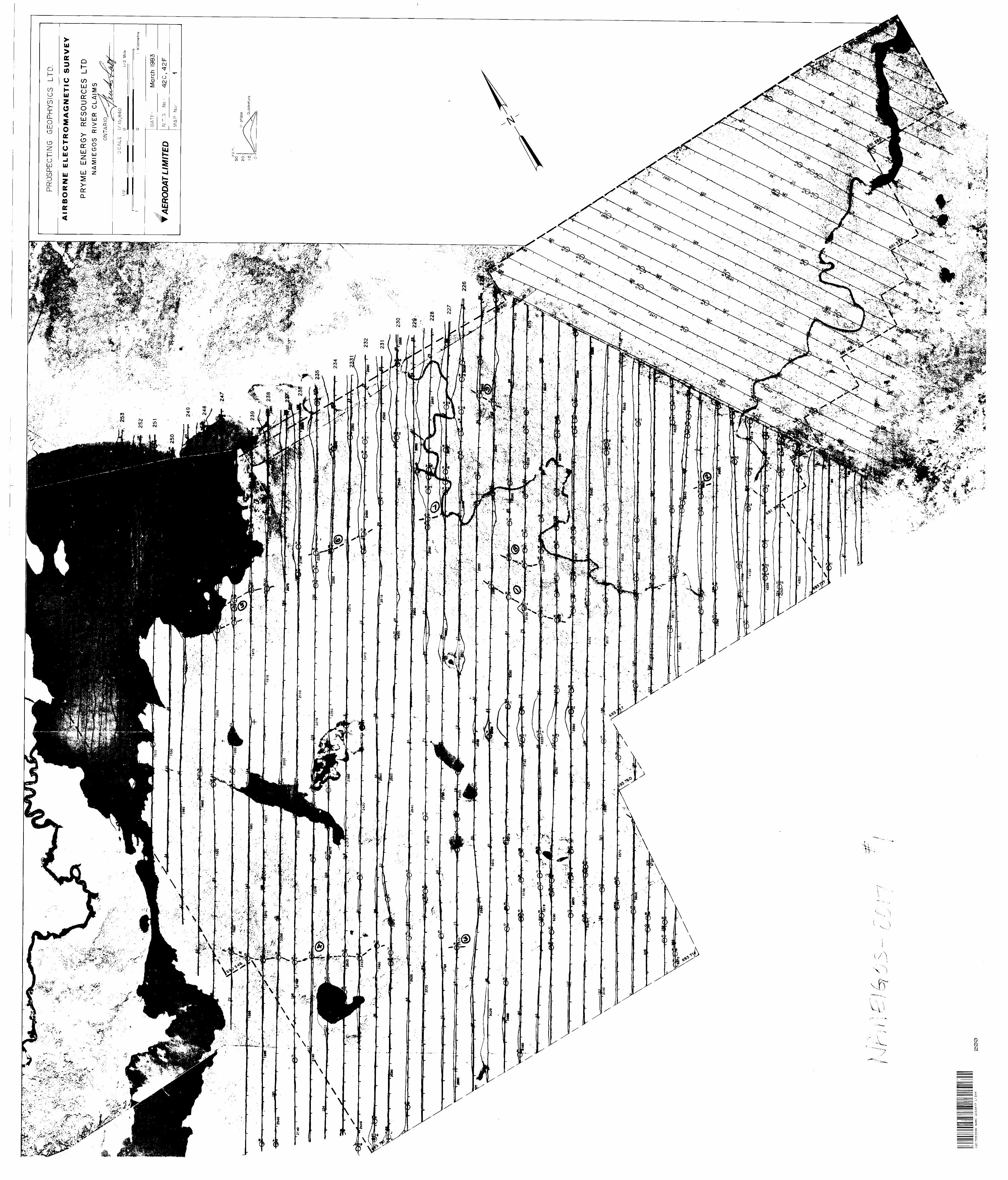
Map 2 Airborne Electromagnetic Survey Profile Map(955 Hz. coaxial)
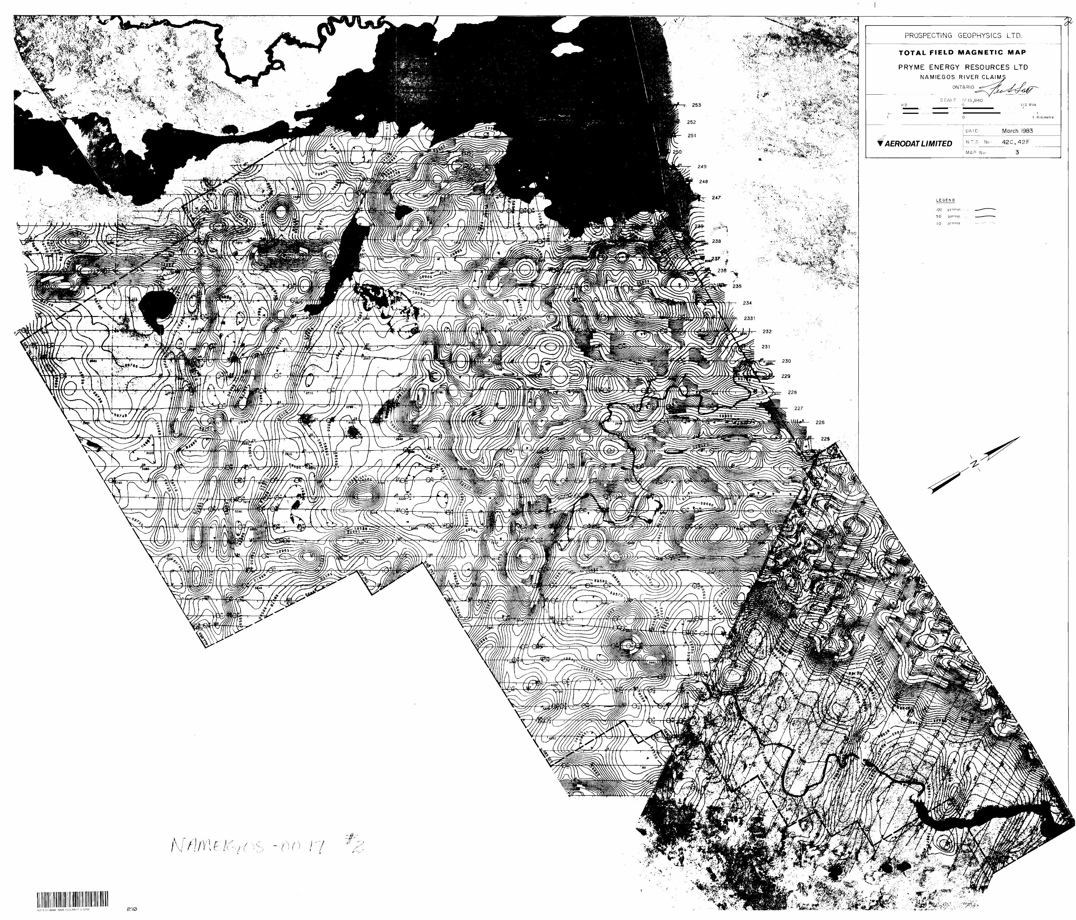
Map 3 Total Field Magnetic Map
Map 4 VLF-EM Total Field Contours
Data provided but not included in report:
1 - master map (2 colour) of coaxial and coplanar profiles with flight path
2 - anomaly l;.s'; providing estimates of depth and conductivity thickness
3 - analogue records of data obtained in flight
1-1
l. INTRODUCTION
This report describes an airborne geophysical survey
carried out on behalf of Pryme Energy Resources Limited
by Aerodat Limited. Equipment operated included a 3
frequency electromagnetic system, a VLF-EM system, and
a magnetometer.
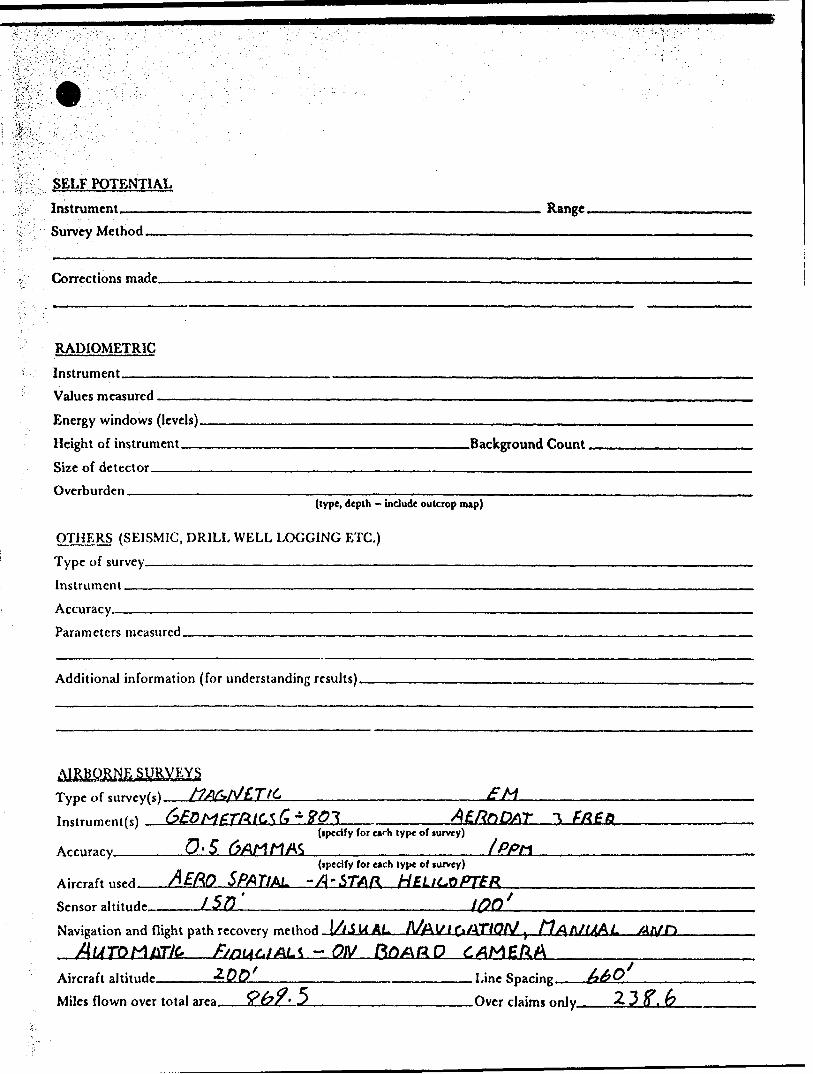
The survey was flown on March 26 to March 29, 1983 from
an operations base at Wawa Ontario. A total of 869.5
line miles were flown, at a nominal line spacing of 660
feet. Of the total flown, this report describes 238.6
line miles.
2-1
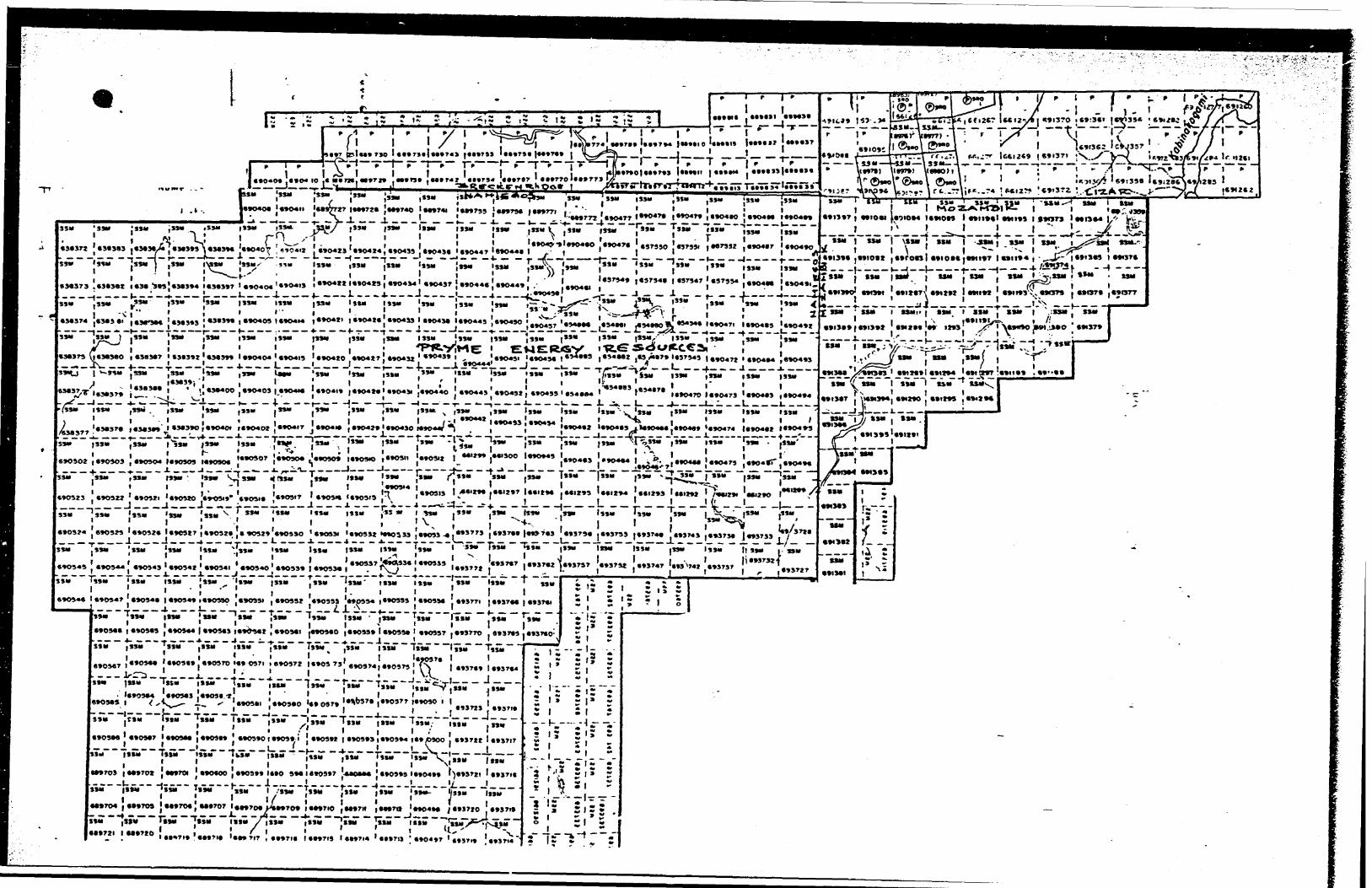
2. SURVEY AREA/CLAIM NUMBERS AND LOCATIONS
The mining claim numbers and locations covered by this
survey are indicated on the map in the following pocket,
3-1
3. AIRCRAFT EQUIPMENT
3.1 Aircraft
The helicopter used for the survey was an Aerospatial
Astar 350D owned and operated by North Star Helicopters.
Installation of the geophysical and ancillary equipment
was carried out by Aerodat. The survey aircraft was
flown at a nominal altitude at 60 meters.
3.2 Equipment
3.2.1 Electromagnetic System
The electromagnetic system was an Aerodat/
Geonics 3 frequency system. Two vertical
coaxial coil pairs were operated at 955 and
4130 Hz and a horizontal coplanar coil pair
at 4500 Hz. The transmitter-receiver separa
tion was 7 meters. In-phase and quadrature
signals were measured simultaneously for the
3 frequencies with a time-constant of 0.1
seconds. The electromagnetic bird was towed
30 meters below the helicopter.
3.2.2 VLF-EM System
The VLF-EM System was a Herz 2A. This instru
ment measures the total field and vertical
3-2
quadrature component of two selected frequencies,
The sensor was towed in a bird 15 meters below
the helicopter.
The sensor aligned with the flight direction
is designated as "LINE", and the sensor
perpendicular to the line direction as "ORTHO".
The "LINE" station used was NAA, Cutler Maine,
17.8 KHz or NLK, Jim Creek Washington, 24.8 KHz.
The "ORTHO" station was NSS, Annapolis Maryland,
21.4 KHz. The NSS transmitter was operating on
a very limited schedule and was not available
during a large part of the survey.
3.2.3 Magnetometer
The magnetometer was a Geometrics G-803 proton
precession type. The sensitivity of the
instrument was l gamma at a 1.0 second sample
rate. The sensor was towed in a bird 15 meters
below the helicopter.
3.2.4 Magnetic Base Station
An IFG proton precession type magnetometer was
operated at the base of operations to record
diurnal variations of the earths magnetic
field. The clock of the base station was
synchronized with that of the airborne system
3-3
to facilitate later correlation.
3.2.5 Radar Altimeter
A Hoffman HRA-100 radar altimeter was used to
record terrain clearance. The output from the
instrument is a linear function of altitude
for maximum accuracy.
3.2.6 Tracking Camera
A Geocam tracking camera was us?ed to record
flight path on 35 mm film. The camera was
operated in strip mode and the fiducial numbers
for cross reference to the analog and digital
data were imprinted on the margin of the film.
H 3.2.7 Analog Recorder
f A RMS dot-matrix recorder was used to display
l the data during the survey. A sample recordifl with channel identification and scales is
* presented on the following page.
l
l**- v,
j't\iy.
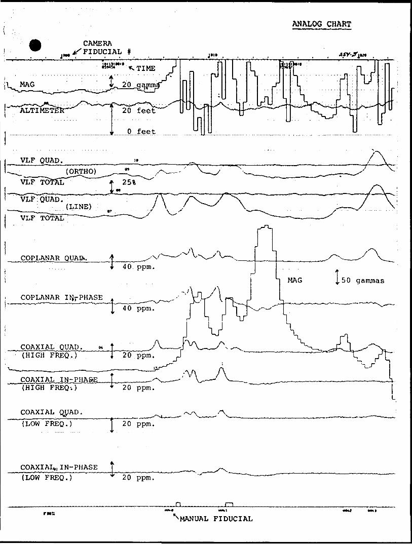
ANALOG CHART
CAMERA ^FIDUCIAL l
VLF QUAD.
COPLANAR QUAD..
COPLANAR IIJ-PHASE
(HIGH FREQ.)
COAXIAL IM-PHAStL t THT^H PRFO." 'i ^^f~(HIGH
COAXIAL qUAD.
2 O ppm.
(LOW FREQ.) T 2 O ppm.
COAXIAL,, IN-PHASE
(LOW FREQ.) 20 ppm.
-OLr w s
^MANUAL FIDUCIAL
ll l
3-4
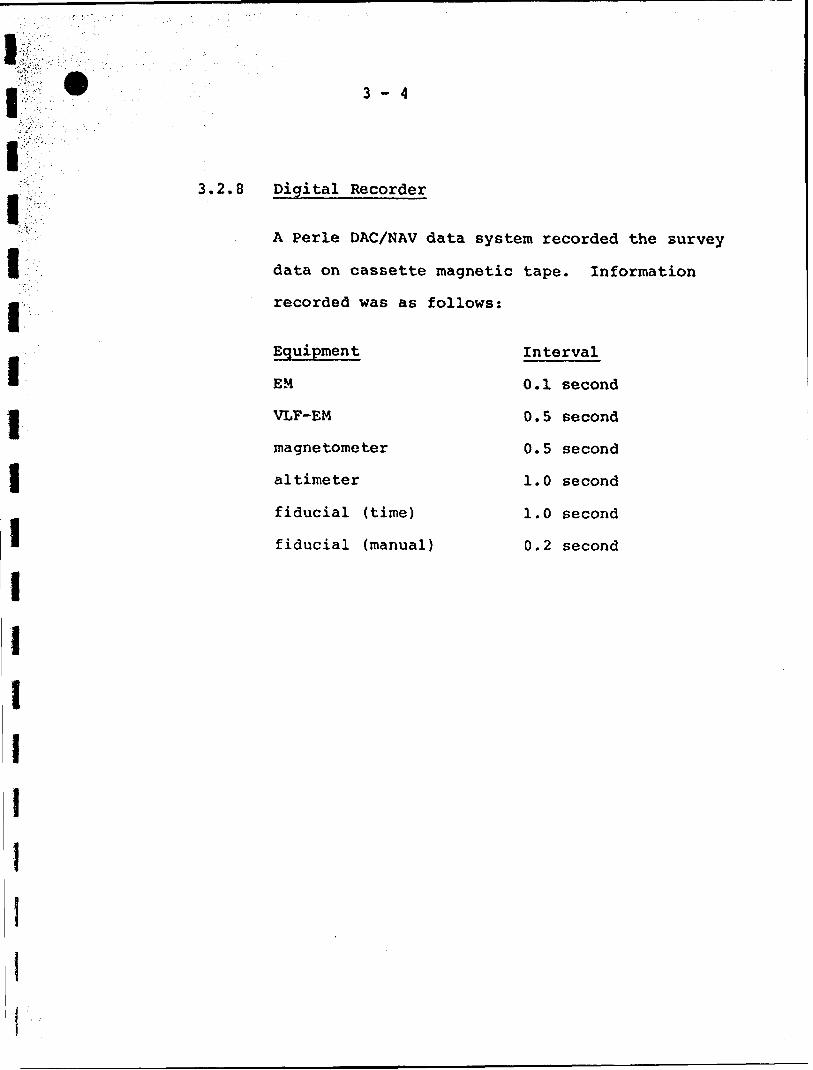
3.2.8 Digital Recorder
A Perle DAC/NAV data system recorded the survey
data on cassette magnetic tape. Information
recorded was as follows:
Equipment
EM
VLF-EM
magnetometer
altimeter
fiducial (time)
fiducial (manual)
Interval
0.1 second
O.5 second
0.5 second
1.0 second
l.O second
O.2 second
l!I I
t J ll
4-1
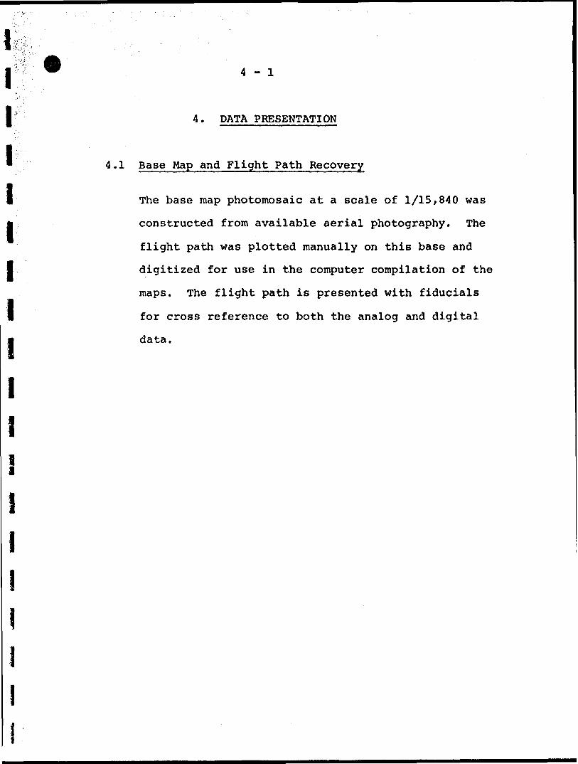
4 - DATA PRESENTATION
4.1 Base Map and Flight Path Recovery
The base map photomosaic at a scale of 1/15,840 was
constructed from available aerial photography. The
flight path was plotted manually on this base and
digitized for use in the computer compilation of the
maps. The flight path is presented with fiducials
for cross reference to both the analog and digital
data.
4-2
4.2 Electromagnetic Profile Maps
The electromagnetic data was recorded digitally at
a high sample rate of 10/second with a small time
constant of 0.1 second. A two stage digital filtering
process was carried out to reject major sferic events,
a*tu reduce system noise.
Local atmospheric activity can produce sharp, large
amplitude events that cannot be removed by conventional
filtering procedures. Smoothing or stacking will reduce
their amplitude but leave a broader residual response
that can be confused with a geological phenomenon. To
avoid this possibility, a computer algorithm searches
out and rejects the major "sferic" events.
The signal to noise was further enhanced by the
application of a low pass filter. The filter was
applied digitally. It has zero phase shift which
prevents any lag or peak displacement from occurring
and it suppresses only variation with a wavelength
less than about 0.25 seconds. This low effective time
constant permits maximum profile shape resolution.
Following the filtering processes, a base level
correction was made. The correction applied is a linear
function of time that ensures that the corrected
amplitude of the various inphase and quadrature components
4-3
is zero when no conductive or permeable source is
present. This filtered and levelled data was then
presented in profile map form.
The in-phase and quadrature responses of the coaxial
955 Hz configuration are plotted with the flight
path and presented on the photomosaic base.
The in-phase and quadrature responses of the coaxial
4500 Hz and the coplanar 4130 Hz configuration are
plotted with flight path and are available as a two
colour overlay.
4-4
Magnetic Contour Maps
The aeromagnetic data was corrected for diurnal
variations by subtraction of the digitally recorded
base station magnetic profile. No correction for
regional variation is applied.
The corrected profile data was interpolated onto a
regular grid at a 2.5 nun interval using a cubic
spline technique. The grid provided the basis for
threading the presented contours at a 10 gamma
interval.
4-5
4.4 VLF-EM Contour and Profile Maps
The VLF-EM "LINE" signal, was compiled in map form.
The mean response level of the total field signal
was removed and the data was gridded and contoured
at an interval of 2%. When the "ORTHO" signal was
available it was compiled in a similar fashion.
4-6
4.5 Electromagnetic Conductor Symbolization
The electromagnetic profile maps were used to
identify those anomalies with characteristics
typical of bedrock conductors. The in-phase
and quadrature response amplitudes at 4130 Hz
were digitally applied to a phasor diagram for
the vertical half-plane model and eotimates of
conductance (conductivity thickness) were made.
The conductance levels were divided into categories
as indicated in the map legend; the higher the number,
the higher the estimated conductivity thickness
product.
As discussed in Appendix I the conductance should be
used as a relative rather than absolute guide to
conductor quality. A conductance value of less than
2 mhos is typical for conductive overburden material
and electrolytic conductoj in faults and shears.
Values greater than 4 mhos generally indicate some
electronic conduction by certain metallic sulphides
and/or graphite. Gold, although highly conductive,
is not expected to occur in sufficient concentration
to directly produce an electromagnetic anomaly;
however, accessory mineralization such as pyrite or
4-7
graphite can produce a measurable response.
With the aid of the profile maps, responses of similar
characteristics may be followed from line to line and
conductor axes identified.
The distinction between conductive bedrock and over
burden anomalies is not always clear and some of
the symbolized anomalies may not be of bedrock origiu.
It is also possible that a response may have been
mistakenly attributed to overburden and therefore not
included in the symbolization process. For this reason,
as geological and other geophysical information becomes
available, reassessment of the significance of the
various cond^tors is recommended.
4-8
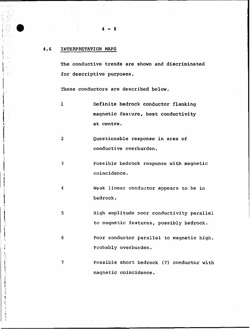
4.6 INTERPRETATION MAPS
The conductive trends are shown and discriminated
for descriptive purposes.
These conductors are described below.
1 Definite bedrock conductor flanking
magnetic feature, best conductivity
at centre.
2 Questionable response in area of
S conductive overburden.
j 3 Possible bedrock response with magnetic
; coincidence.
j; 4 Weak linear conductor appears to be in
i bedrock.
j 5 High amplitude poor conductivity parallelt
' to magnetic features, possibly bedrock.
i; 6 Poor conductor parallel to magnetic high.
i Probably overburden.
l 7 Possible short bedrock (?) conductor withi-j magnetic coincidence.
4-9
8
9
Questionable conductor on magnetic high.
Questionable x-nit at edge of overburden
response.
Respectfully submitted,
August 8, 1983. Fenton Scott, P.Eng.
APPENDIX I
GENERAL INTERPRETIVE CONSIDERATIONS
Electromagnetic
The Aerod t 3 frequency system utilizes 2 different
transmitter-receiver coil geometries. The traditional
coaxial coix configuration is operated at 2 widely
separated frequencies and the horizontal coplanar coil
pair is operated at a frequency approximately aligned
with one of the coaxial frequencies.
The electromagnetic response measured by the helicopter
system is a function of the "electrical" and "geometrical"
properties of the conductor. The "electrical" property
of a conductor is determined largely by its conductivity
and its size and shape; the "geometrical" property of the
response is largely a function of the conductors shape and
orientation with respect to the measuring transmitter and
receiver.
Electrical Considerations
For a given conductive body the measure of its conductivity
or conductance is closely related to the measured phase
shift between the received and transmitted electromagnetic
field. A small phase shift indicates a relatively high
conductance, a large phase shift lower conductance. A
small phase shift results in a large in-phase to quadrature
- 2 - APPENDIX I
ratio and a large phase shift a low ratio. This relation
ship is shown quantitatively for a vertical half-plane
model on the accompanying phasor diagram. Other physical
models will show the same trend but different quantitative
relationships.
The phasor diagram for the vertical half-plane model/ as
presented, is for the coaxial coil configuration with the
amplitudes in ppm as measured at the response peak over
the conductor. To assist the interpretation of the survey
results the computer is used to identify the apparent
conductance and depth at selected anomalies. The results
of this calculation are presented in table form in Appendix I
and the conductance and in-phase amplitude are presented
in symbolized form on the map presentation.
The conductance and depth values as presented are correct
only as far as the model approximates the real geological
situation. The actual geological source may be of limited
length, have significant dip, its conductivity and thickness
may vary with depth and/or strike and adjacent bodies and
overburden may have modified the response. In general the
conductance estimate is less affected by these limitations
than the depth estimate but both should be considered a
relative rather than absolute guide to the anomalies
properties.
- 3 - APPENDIX I
Conductance in mhos is the reciprocal of recistance in
ohms and in the case of narrow slab like bodies is the
product of electrical conductivity and thickness.
Most overburden will have an indicated conductance of less
than 2 mhos; however, more conductive clays may have an
apparent conductance of say 2 to 4 mhos. Also in the low
conductance range will be electrolytic conductors in faults
and shears.
The higher ranges of conductance, greater than 4 mhos,
indicate that a significant fraction of the electrical
conduction is electronic rather than electrolytic in nature.
Materials that conduct electronically are limited to certain
metallic sulphides and to graphite. High conductance
anomalies, roughly 10 rahos or greater are generally limited
to sulphide or graphite bearing rocks.
Sulphide minerals with the exception of sphalerite, cinnabar
and stibnite are good conductors; however, they may occur
in a disseminated manner that inhibits electrical conduction
through the rock mass. In this case the apparent conductance
can seriously under rate the quality of the conductor in
geological terms. In a similar sense the relatively non
conducting sulphide minerals noted above may be present in
significant concentration in association with minor conductive
- 4 - APPENDIX I
sulphides, and the electromagnetic response only relate
to the minor associate mineralization. Indicated conductance
is also of little direct significance for the identification
of gold mineralization. Although gold is highly conductive
it would not be expected to exist in sufficient quantity
to create a recognizable anomaly but minor accessory sulphide
mineralization could provide a useful indirect indication.
In summary the estimated conductance of a conductor can
provide a relatively positive identification of significant
sulphide or rraphite mineralization; however, a moderate
to low conductance value does not rule out the possibility
of significant economic mineralization.
Geometrical Considerations
Geometrical information about the geologic conductor can
often be interpreted from the profile shape of the anomaly.
The change in shape is primarily related to the change in
inductive coupling among the transmitter, the target, and
the receiver.
In the case of a thin, steeply dipping, sheet-like conductor,
the coaxial coil pair will yield a near symmetric peak over
the conductor. On the other hand the coplanar coil pair will
pass through a null couple relationship and yield a minimum
over the conductor, flanked by positive side lobes. As the
dip of the conductor decreases from vertical, the coaxial
- 5 - APPENDIX J
anomaly shape changes only slightly, but in the case of
the coplanar coil pair the side lobe on the down dip side
strengthens relative to that on the up dip side.
As the thickness of the conductor increases, induced
current flow across the thickness of the conductor becomes
relatively significant and complete null coupling with the
coplanar coils is no longer possible. As a result, the
apparent minimum of the coplanar response over the conductor
diminishes with increasing thickness, and in the limiting
case of a fully 3 dimensional body or a horizontal layer
or half-space, the minimum disappears completely.
A horizontal conducting layer such as overburden will produce
a response in the coaxial and coplanar coils that is a
function of altitude (and conductivity if not uniform). The
profile shape will be similar in both coil configurations
with an amplitude ratio (coplanar/coaxial) of about 4/1.
In the case of a spherical conductor, the induced currents
are confined to the volume of the sphere, but not relatively
restricted to any arbitrary plane as in the case of a sheet-
like form. The response of the coplanar coil pair directly*
over the sphere r;.ay be up to 8 times greater than that of
the coa;:i^i coil pair.
- 6 - APPENDIX I
In summary a steeply dipping, sheet-like conductor will
display a decrease in the coplanar response coincident
with the peak of the coaxial response. The relative
strength of this coplanar null is related inversely to
the thickness of the conductor; a pronounced null indicates
a relatively thin conductor. The dip of such a conductor
can be infered from the relative amplitudes of the side-lobes.
Massive conductors that could be approximated by a conducting
sphere will display a simple single peak profile form on both
coaxial and coplanar coils, with a ratio between the coplanar
to coaxial response amplitudes as high as 8.*
Overburden anomalies often produce broad poorly defined
anomaly profiles. In most cases the response of the coplanar
coils closely follow that of the coaxial coils with a
relative amplitude ratio of 4.*
Occasionally if the edge of an overburden zone is sharply
defined with some significant depth extent, an edge effect
will occur in the coaxial coils. In the case of a horizontal
conductive ring or ribbon, the coaxial response will consist
of two peaks, one over each edge; whereas the coplanar coil
will yield a single peak.
- 7 - APPENDIX I
* It should be noted at this point that Aerodat's definition
of the measured ppm unit is related to the primary field
sensed in the receiving coil without normalization to the
maximum coupled (coaxial configuration). If such normal
ization were applied to the Aerodat units, the amplitude
of the coplanar coil pair would be halved.
- 8 - APPENDIX I
Magnetics
The Total Field Magnetic Map shows contours of the
total magnetic field, uncorrected for regional varia
tion. Whether an EM anomaly with a magnetic correla
tion is more likely to be caused by a sulphide deposit
than one without depends on the type of mineralization.
An apparent coincidence between an EM and a magnetic
anomaly may be caused by a conductor which is also
magnetic, or by a conductor which lies in close proximity
to a magnetic body. The majority of conductors which are
also magnetic are sulphides containing pyrrhotite and/or
magnetite. Conductive and magnetic bodies in close
association can be, and often are, graphite and magnetite.
It is often very difficult to distinguish between these
cases. If the conductor is also magnetic, it will usually
produce an EM anomaly whose general pattern resembles
that of the magnetics. Depending on the magnetic perme
ability of the conducting body, the amplitude of the
inphase EM anomaly will be weakened, and if the conduc
tivity is also weak, the inphase EM anomaly may even be
reversed in sign.
k 4) - 9 - APPENDIX I
r..
l VLF ElectromagneticstB The VLF-EM method employs the radiation from powerful
f military radio transmitters as the primary signals.
P The magnetic field associated with the primary field
|l is elliptically polarized in the vicinity of electrical
- conductors. The Herz Totem uses three coils in the X.
Y. Z. configuration to measure the total field and
vertical quadrature component of the polarization
P ellipse.
gj The relatively high frequency of VLF 15-25 KHz provides
^ high response factors lor bodies of low conductance .
p Relatively "disconnected" sulphide ores have been found
l to produce measurable VLF signals. For the same reason,
i poor conductors such as sheared contacts, breccia zones,
P narrow faults, alteration zones and porous flow tops normallyt.
g produce VLF anomalies. The method can therefore be used
P effectively for geological mapping. The only relative dis-
8 advantage of the method lies in its sensitivity to conductive
overburden. In conductive ground the depth of exploration
is severely limited.
jj The effect of strike direction is important in the sensei.^ of the relation of the conductor axis relative to the
P energizing electromagnetic field. A conductor aligned*
H along a radius drawn from a transmitting station will be
i
- 10 - APPENDIX I
in a maximum coupled orientation and thereby produce a
stronger response than a similar conductor at a different
strike angle. Theoretically it would be possible for a
conductor, oriented tangentially to the transmitter to
produce no signal. The most obvious effect of the strike
angle consideration is that conductors favourably oriented
with respect to the transmitter location and also near
perpendicular to the flight direction are most clearly
rendered and usually dominate the map presentation.
The total field response is an indicator of the existence
and position of a conductivity anomaly. The response will
be a maximum over the conductor, without any special filtering,
and strongly favour the upper edge of the conductor even in
the case of a relatively shallow dip.
The vertical quadrature component over steeply dipping sheet
like conductor will be a cross-over type response with the
cross-over closely associated with the upper edge of the
conductor.
The response is a cross-over type due to the fact that it
is the vertical rather than total field quadrature component
that is measured. The response shape is due largely to
geometrical rather than conductivity considerations and
the distance between the maximum and minimum on either side
of the cross-over is related to target depth. For a given
target geometry, the larger this distance the greater the
- 11 - APPENDIX I
depth.
The amplitude of the quadrature response, as opposed
to shape is function of target conductance and depth
as well as the conductivity of the overburden and host
rock. As the primary field travels down to the conductor
through conductive material it is both attenuated and
phase shifted in a negative sense. The secondary field
produced by this altered field at the target also has an
associated phase shift. This phase shift is positive and
is larger for relatively poor conductors. This secondary
field is attenuated and phase shifted in a negative sense
during return travel to the surface. The net effect of
these 3 phase shifts determine the phase of the secondary
field sensed at the receiver.
A relatively poor conductor in resistive ground will yield
a net positive phase shift. A relatively good conductor
in more conductive ground will yield a net negative phase
shift. A combination is possible whereny the net phase
shift is zero and the response is purely in-phase with no
quadrature component.
A net positiv phase shift combined with the geometrical
cross-over shape will lead to a positive quadrature response
on the side of approach and a negative on the side of
departure. A net negative phase sh^ft would produce the
reverse. A further sign reversal occurs with a 180 degree
" 12 " APPENDIX I \~ t
change in instrument orientation as occurs on reciprocal j
line headings. During digital processing of the quad
rature data for map presentation this is corrected for
by normalizing the sign to one of the flight line headings.
LIZAR
Initial Check900
Assessed
Approved Reports of Work sent out
Notice of Intent filed
Approval after Notice of Intent sent out
Duplicate sent to Resident Geologist
Duplicate sent to A.F.R.O.
i .t
— - —— r -- —— pP*" i"- J**- [S- IS1*9040* j**0*ll j**9W* 14*972* J*
J:.-.,--.-..- -X-i- — J-
'•••72*,*t*719 ,***TS* , ***7*2j ***73* j***787 '***77O 49977S lkDch*
I r?r * i* l y i '^^^JT^ 'X r i ^ P ' ' ' i f l I * 7 \ \ M *4jV774!***7**U**7*4 |4***IO '••••l* |****1* '•••t ••T {23(44*7*0 I •••7s*|***74S t***rss I***TS* |***T** 'fv-y'^.Ji— .J _ ___ l _ ' ' — ' . _ '"1"""1"""1"'" — ̂- -T-— v^-rjfT i , T'~T ~~~—.r:..
1 4*0*0* ,4*o* 10i — -J —— r*" "- *
[4*9740 4*97*1 J**9799 j 4*9734 |**97Tl'••**977l! 1*90477 l****** |*90479 |*904*0 !*904M I4*O4*9
-4- — — —r- — — T ~ — ^ — ——-4— — — — V— — — .• ••t* ' 9.4M l 9.ftM I*VM l__.. ,--
•7*o|4**r*j ****!! j ••••M j ••••i9|****i*
i*T*rlr**T*3 '7 tm ̂ '^'•'•••TT Tj*** iTi**5!"5*
'•9049--91*904*0 .4*0*74*9IO*t |*91t97 1*91194,-
—u-—li"~""~" ~~~"'""~* " "
••is** i c*is*t
'*3*979 j _
L,T, *9*57* ,.34S*V 1*3*390, •90401 IC*O*OZ3 : . —-.*- — -Si..'-j.---a. - —
SSM
l ' l /i' •**M* 14*0*93 ! 4*0.** ' ' ^* ]**0*IT J 4*0*14 , 4*0*29 ' 4*0*SO 14*oW*i . , J "W"* J4*O*42 l4*O*43i
T5? ^"ss.?"""^*! ,SSM |s*M ~|^,- ~~J*'M~~JSSM~ [s*VT~ ,Tsi" M
Ji.0^0. '..^909 j.909* !**09n '.9O9.Z t •*** ,——3OO 1.90^9 J..^ l ^^ • -' t i * ."~ .1 l l J^ T , 4*0*4* [4*0*73 ,490'ST^
**II9* '44.1*2 l /V*IZ9t '**I290 l*****/•90919 l **'"* .4412*7 I**lt9* .4412*3 14412**
., .^S.0 .^,5, .W5. , ^ILL
SSM TSSH JSSM ISSH 'SSM "li^, ~~ji",i;~ TsSM " ~'sSM ' ~ ItSM 7ssV !"sSM ~ ~ (SSM* ~ "^ ~ MM"
' ' l ' . |.l l l l ••09*7 J **OS** |**094* i ••0990 ( *9O99I , ••O9SI •*O331 '**O33* |**O99* '4*0354 ' 4*5TT. | 4*3TM ) •*}r*l
SM "JSSM ~ I*SM J **M ~ "js**" ~ TS*M~ ~ ISSM" lsSM~~|s*i~~ JSSM"~~ITSM" ~|^SM ~ Is* ~ -
SM
•90***
SSM
••0940—
SSM
•' I**O9*A '
•9O9M **03*7 l 4*034* J *9O9*9••~.. flto*.*.' M ls* ISSM TSSM~ ""ISSM" ~'
i ' '(•97O3 l **970t J M97OI J 49O4OO
.,097, ..0977
**O3*O l **O9* l ••O9M | 4*O3*S | **O9*4 1 4*
ISSM l
l "M l
SSM sw,
**S7tt l **S7I7
•*O3,* 14*O 9MI**O9*7 4*O3*3 I4*O****v*r v^ (wvfv* j wwvrvi vwvvv VW3VV l * w 9 w l VTU3V' -4WW*** " VV97V9 l **O4*9 ']W*3TII **9}7I*
SSM ,SSM SSM SSM )M- J ,,^, JW, ,M tw, j,^ j,,,, ,M-
*9704 , 0*709 J •••TO* | ***70T l, **97O*^t**7O* l ***7IO }***7II | ***7tt '*9049* J **S7tO ! *9S7I*
*M Js*V~ ~ TiJ - TfwM" ~ |.,M "/[sSlT ^SM ~ ~j7si" ~ ]SSM~ ~!MH ~ "^'sSlp^-v^SM" ~
*9721 l ***720 , ,,,T|, '.,,TI, U**7I7 , **97I* 14*9719 l ***7l4 '•••71* ' *9O*97 '4937^ ' *937M "
l *9O9*9 , 4*09** l •9O9413 1*9(71142 , 49O941 |69O34O |*9O999 I *9O99* l **O997 | **377O 6937*3 J *9S7*0 :
ISSM "''S'SM IS'SM" ~ IS^M" "" TSSM~ ~ TssV ~ "!SSM~ ~ | SSM" ~ ISSM' ~ ~l MM" "~ T.i~ ~ - . ' l l - i l * i l i i * "
, 4*034* 1*909*9.890970 1*9 O97I l 8*0372 | **O9 73' fl*o3T* j **O979 '"f^** l (937*9 l 7 5 l*
I l
* l
l Zl*
•VISIT ,
t **™ ' Jj™^-.- 9*MB 'ftftM -i-***l NVO •3L*. I-IT&I tt- t i
(*OIO*4 1*910*9 l *9M**I i
l* l l l l
"SSH ~|~ vis*)"! "SSH | ~-3s*i1" "sin "l SSM
j j, VtlOW (.
* S
SELF POTENTIAL Instrument.———— Range.Survey Method.
Corrections made.
RADIOMETRICInstrument.Values measured.
Energy windows (levels). Height of instrument—— Size of detector————Overburden ,———————
.Background Count.
(type, depth - include outcrop map)
OTHERS (SEISMIC, DRILL WELL LOGGING ETC.) Type of survey-————————.——.—.—————.——-.Instrument —————————————————————————— Accuracy_________________________Parameters measured.
Additional information (for understanding results).
RI3RNEType of survey(s) Instrument(s) —
f M
AERnDAT
Accuracy(ipecify for wh type of turvty)
O'B 6Ar\npti __ IPPKAircraft used
(ipecify for each type of turvey)
Sensor altitude_ isnNavigation and flight path recovery method l// J (A AL /I/A l/ 1 t D
- ON
Aircraft altitude.Miles flown over total an-a yfc?X'
.Line Spacing.
.Over claims only___^ 3 Q .
Ontario
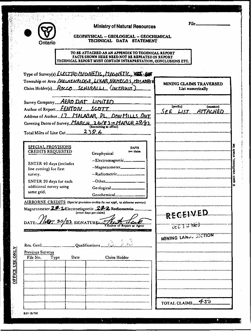
Ministry of Natural Resources
GEOPHYSICAL - GEOLOGICAL - GEOCHEMICAL TECHNICAL DATA STATEMENT
FUe.
TO BE ATTACHED A3 AN APPENDIX TO TECHNICAL REPORTFACTS SHOWN HERE NEED NOT BE REPEATED IN REPORT
TECHNICAL REPORT MUST CONTAIN INTERPRETATION, CONCLUSIONS ETC.
gtdSSu.h.O
Type of Survey(s) Township or Area Claim
Li *Af{flME(*0 1 Ho^ AtJBf fc
XlfflQ DAT
Author of Report FfcMTbM .S6-O7TAddress of Anther 1 7 MALAGA!^ PL DfifJ HlLLS
Covering Dates of Survey.
Total Miles of Line Cu^
2. y/ff 3 -*(Hnccutting to office)
SPECIAL PROVISIONS CREDITS REQUESTED
ENTER 40 days (includes line cutting) for first survey.
ENTER 20 days for each additional survey using same grid.
Geophysical-Electromagnetic.—Magnetometer.——Radiometric——
-Other—-———-
DAYS per claim
Geological.Geochemical.
AIRBORNE CREDITS (Special provision credit! do not appl, to airborne mrveyi)
MagnetometerJSLj^lrElectrorrfagnetic
DATE:
(enter dayt per claim)
SIGNATURE*
Res. Geol.. .Qualifications.Previous Surveys
File No. Type Date Claim Holder
MINING CLAIMS TRAVERSED List numerically
{prefix) (number)
I i
Ut b i ^
M\NtNG
TOTAL CLAIMS.
B37 16/79)
Ministry olNaturalResources
Ontario
Report of Work(Geophysical, Geological, Geochemical and Expenditures)
The Mining Act
Instructions: - Pleasa type or print.- H number ol mining 'claims traversed
exceeds space on this form, attach a list. a: — Only .days credits calculated in the
"Expenditures" section may ba entered in the "Expand. Dayt Cr." columns.
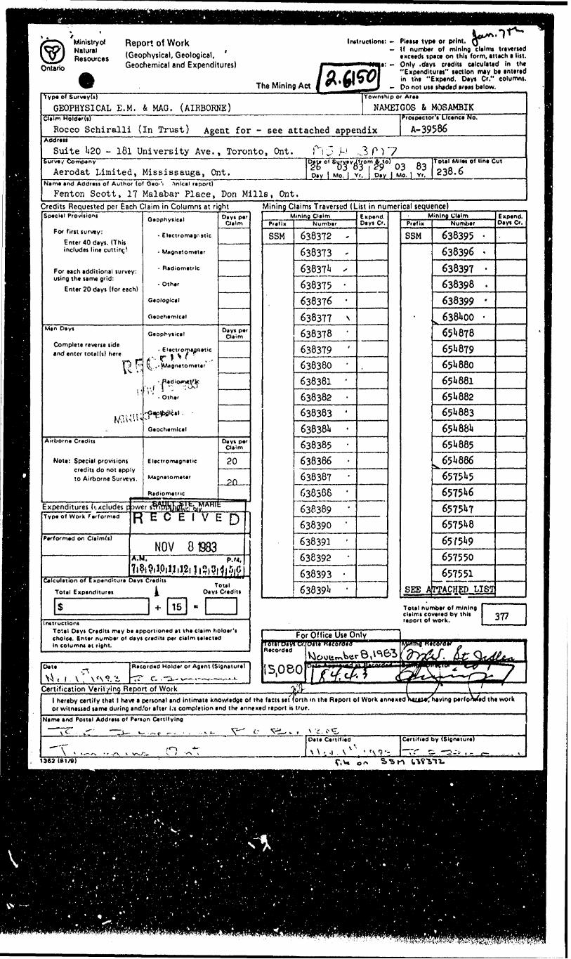
— Do not us* shaded araas below.Type Of Survey(s)
GEOPHYSICAL E. M. fc MAG. (AIRBORNE)Claim Holder(s)
Rocco Schiralli (in Trust) Agent for - see attachedAddress
Suite 1*20 - 181 University Ave. , Toronto, Ont. f");.Survey Company P/*,}* o *
Aerodat Limited, Mississauga, Ont. D, y |Nema and Address of Author (of Geo-"i ^nlctl report)
Fenton Scott, IT Malabar Place, Don Mills, Ont.
Township or Arae
NAMEIGOS tt MOSAMBIK
appendix
3 P .3 p ) 7
Prospector'i Licence No.
A- 39586
^TeTT^0' 03 83Mo. | Vr. j Day | Mo. j Vr.
Total Mllw of Una Cut
238.6
Credits Requested per Each Claim in Columns at rightSpecial Provisions
For first survey:
E mer 40 days. (This includes line cutting
For each additional survey: using the same grid:
Enter 20 days (for each)
Man Days
Complete reverse side and enter total (s) here
RF;1 '
Airborne Credits
Note: Special provisions credits do not apply to Airborne Surveys.
9**"^
Geophysical
- Electromagnetic
- Magnetometer
- Radiometric
- Other
Geological
Geochemical
Geophysicel
- Electromagnetic*--rlV ? ..,l^. .-^Magnetometer
•.Radiom*,\'lc-,,( } -; ;^
- Other
-Gep^bfllcal
Geochemical
Electromagnetic
Magnetometer
Radiometric
Expenditures kxcludes p iwer sMWHImfe'cPQitf'^"^
Days par Da m
Days perClaim
Days perClaim
20
psaai* .
Type of Work farformad fi E C E 1 V E fi
Performed on Cltlmd)
NOV 01983A.M. p.M,
(1 vi vily|j J il2|l|n|3|4j liiGCalculation of Expenditure Days Credit!
, Total Total Expenditures ^ Days Credits
S 1 + 15 -Instructions
To'.al Days Credits may ba apportioned at the claim holoer'i choice. Enter number of days credits per claim selected In columns et right.
Minino Claims Traversed (List in numerical sequence)Mining Claim
Prefix
SSM
Number
638372 '
638373 '
63837!* '
638375 '
638376 '
638377 N
638378 '
638379 '
638380 '
638381 '
638382 '
638383 '
638381* '
638385 "
638386 '
63838? '
638386 '
638389 '
638390 '
638391 '
638392 '638393 -63839 1* '
Expand. Dayi Cr.
Mining ClaimPrefix
SSM
SEE A
Number
638395 '
638396 '
638397 '
638398 -
638399 '
^ 6381400 -65^878651*879651*880651*881651*882651*883651*881*651*885
^651*88665751*565751*665751*76575**865751*9657550657551
TTACHED LIST
Expend. Day* Cr.
Total number of mining claimi covered by (hit 077 report Of work. Jl
Date
Vi, 1•n
\ v \ fs*?.'iR*CO'd*d Hold*r or Agtnt (Signttur*)
Certification Verifying Report of Work1 hereby certify that 1 have a pertonal and intimate knowledge of the facit tet orth in the Report ol Work annexed i or witneiied tame during and/or alter l.t completion and Ihr annexed report it true.
Name and Poital Addrati of Panon Certifying
1962 (61/fi) o*
"Winistryof
Resource)*V Ontario
Report of Work(Geophysical, Geological. Geochemical and Expenditures)
Instruction*: - Pleat* typ* or print.- If number Of mining clelrra utvtrttd
exceed* spec* on thii form, etttch * lilt Moir - Only d*yt credits calculated In J h*
"Expenditures" ttction miy b* entered in ih* "Expend. Days Cr." column*.
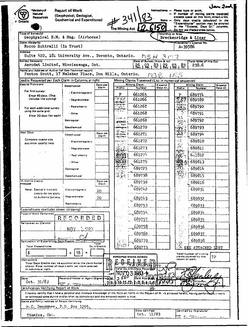
Geophysical E. M. i Mag. (Airborne)Claim Holderls)
Rocco Schiralli (In Trust)Address
Suite Ii20, l8l University Ave., Toronto, OntarioSurvey Company
Aerodat Limited, Mississauga, Ont.
vJBreckenridge
- r\SH 3 mDate of Survey (from ft to)
It Lizar }.
A- 39586
?l ft
Total Mile* of lin* Cut238.6
Name arvj Address of Author (of Oeo-Teehnlcel report)Fenton Scott, 17 Malabar Place, Don Mills, Ontario. fM o p ; /O ^
l ' t ) l J f ri t. J
Credits Requested per Each Claim in Columns at right Mjning Claims Traversed (List in numerical sequence)
f
Special Provisions
For first survey:Enter 40 days. (This includes line cutting)
For each additional survey: using the same grid:
Enter 20 days (for each)
Man Deys
Complete reverse side and enter total(s) here
fA.roorr.e Credits
Note: Special p'Oyisions creaiti do not apply to Airborne Surveys.
O.ophy.ic.1 D'V',^
- Electromagnetic
- Magnetometer
- Radicmetric
- Other
Geological
Geochemical
G.ophy.ic.1 O',?,*''
- Electromagnetic J
- Magn*tomater j
-s.d^metric
- Othajr
Geological
Geochamicat
Do y t perClaim
Electromagnetic pfi
1 Magnetometer : p ri
Radiometric
Expenditures (excludes power stripping)Typ
RFCPerformed on Oaim(s)
Ceic
-IJO^j
Total Expenditures
S -J-
0 R D E D
1 '- w
C^f .i
Total De. 's Credits
15 =Instructions fp
Totel Days Credits may be eppurtio-iad at the claim holder' l L choice. Enter number of days crediu per claim selected j t in columns at right. LI
p
j
.™*4
Date Recorded Holder or Ager.t (Signet i 'e Jo,Oct. 31/83 -^ c .-^^^ __ J
M.8)
Mining ClaimPrefix Number
P 66126522g 661266ZSS 661267
661268''a^y j 661269
r^-- 661270^5: 661271-- ;.-— 661272j^g 661273:^^|; 66l2Y'i
^ff 661275.^;,*.'i X•^sn: ^689725-^2* 689738;. :' : 689739
6897^2
6827^1689J53
' 68975146891^-L
L 689769O- -i: j , 689IIO ..•*' * -' ; .'' i ^
•-OV^V 68Q77?
Expend. Deys Cr.
——————
OnCUPINE MININO DIVISION
^ W ^FrJt OVfirJpUJj GTotal De te Cr. Date RecorQff
^53831983^3 #60 teairspi.^,-
"v J s^^• -rrm\m
Mining ClaimPrefix Number
P 689771*'S^ 689789
;3Si 689T90, t1 ' ^89791Vi 'v,
'y.;v.4.. 689792^^ 689793^rtfl.'" ^68979!*
",- 689810 'v'~ '~-
jj.;;^ 689811'i&lv, 6o';Sl2
t -f, 689813 .'**'
,.MtJv 6898114
'•^' 689815
•" ^689816
689831
689,832
689.833
.689831'
', . J?82836^.'i:\ -689.831,..
, li',. . 689838
——
- : -'- SEE ATTACHED I
Total number ol riming c^aim* covered bv T^it report of work.
Expend. Days Cr.
—————
1ST
72
)Mining Q&fUdJ'S * s*
Jj&t&Jhy^^^'^'^jf^L {/A*i^rni?jr~
Certification Verifying Repot of Work •vfo { J ^ y1 hereby certify that 1 have a personal and intimate knowledge of the facts tot forth in the Report ol W 'rk annexed herJtoThavmg perlorrnVjXnc work or witnessed tame dunne end/or after its completion and the annexed report is true.
Name and Pom! Address of Person Certifying
h. C. Denommee, P.O. Box 1205,
Timir-ins, On';.Dete CertifiedOct. 51/83
Certified by (Signature)
i l -*'f -,'-..-
'' j
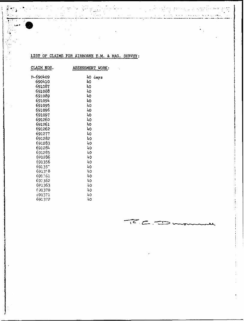
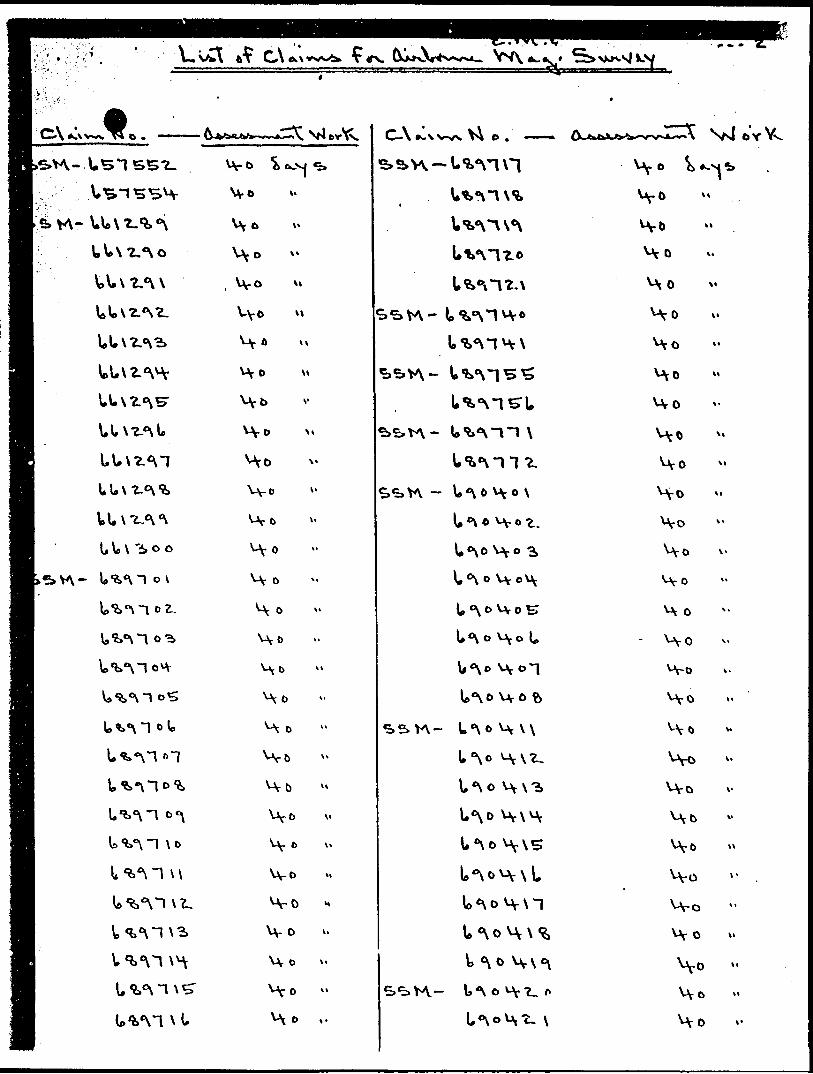
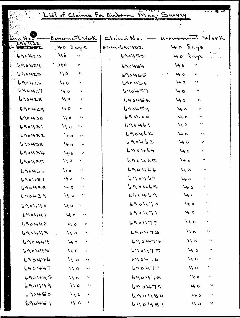
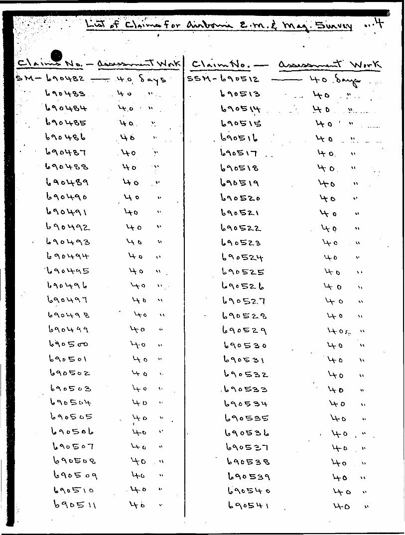
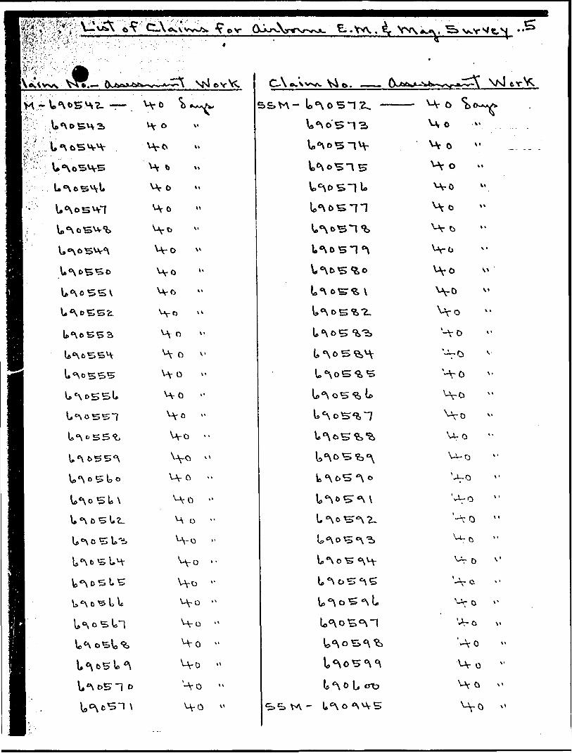
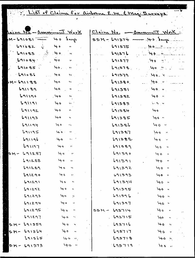
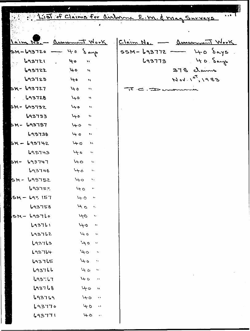
LIST OF CLAIMS FOR AIRBORNE E.M. 4 MAG. SURVEY:
CLAIM NOS.
P-690U096901*10691087691088691089691091*691095691096691097691260691261691262691277691282691283691281*69128569128669135669135 176913C 8691 ".6169] 362691363691370691371691372
ASSESSMENT WORK:
1*0 days1*01*01*01*01*01*01*01*01*01*01*01*01*01*01*01*01*01*01*01*01*01*01*0liO1*01*0
\ l Rocco Schiralli (In Trust) is rfgent for the following;
ti 'fc::',,--. -:- - - :'-;'.^ -'
a Exploration Company, Limited (NPL) A.34387
Denis DeSerres K.19783
.f.557-
U \c \
o \
\\ \t.
L^^T
U^M
^XV4,
Vvo
\VD
V\o
H
V\ 0
\-v
C-\ o .
vyo
U*\o
U*\t)
bVYv*-N4S
v\o
HoHoHoHo
Ho
Ho
Ho
Ho
Ho
VYO
H-o
Ho
Ho
H-o
Ho
Ho
Ho
Ve 0
Ho *' Ho v.
Ho
VV 0 v
V\ O x-
H o
u,o -
HO v-
H o i
H o H o
HO "
\-\ o
HOH DHo
Uf o
H o
o v 'r O
C-\^
U *N c H- U 1
U*\oH"12*
o H ̂
Ho
HO
Ho
Ho
H o
H o
H&
H o
Ho
H o
Ho
1C5E p? C-\y
C-\ *. \i—e* V4 tk. —
cro
o \
U *\
o
\\
- AV o
Wo
H t* Ho Ho HO
Ho
Ho
H o
Ho
HbHo
H-b
Ho
H-o
Wb
•H-
H o Ho Ho Ho.Ho
Ho H oHQHo
Ho
Ho
H o
Ho
Ho
Ho
HoHoHo
H/ o
O k-
Ho v
O V E..VW.. ^v. ..s
M VrVN o S H Z- -r—
v ./,r*,v"' Ir;-., t **
o
Vyo
VY o Ho
Ho
Ho
Ho
Ho
', C-\
Mr O a
^V O 1
HoO
O *
'-Vo H-o
U-oVv-o'0-0
'a- o
-r O '-Ve
vJr- Q
'A- O
o
CA O V fc. .Vxv . i
.W-
V
Vs '\\\ l\\
\* e\\\ c\~]
^
\ \
\\-tt \\
UT b
C.\ e .
\*\
l*-^k.
Mr 6.H-o
HOV-. *^
Ho
Ho
HO
Ho
H-o
Ht* H-o
Ho
H-6
H t
lw
iVV-
,H-
OvkAjk
t\
M
Wo
Wo
i e .
Ho
Vi
•^—~cr~
(J1
1983 12 20 Your File: Our File:
3412.6150
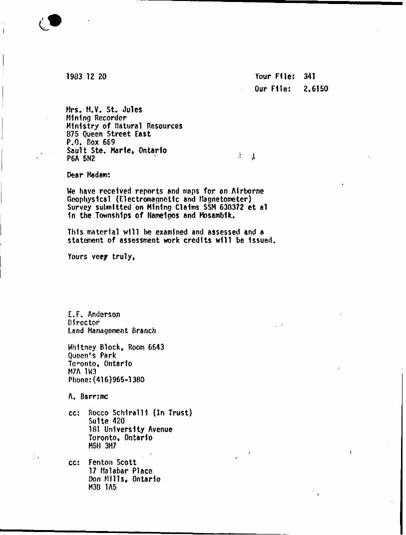
Mrs. M.V. St. JulesMining RecorderMinistry of Natural Resources875 Queen Street EastP.O. Box 669Sault Ste. Marie, OntarioP6A 5N2 ' '.l
Dear Madam:
We have received reports and maps for an Airborne Geophysical (Flectromagnotlc and Magnetometer) Survey submitted on Mining Claims SSM 630372 et al 1n the Townships of Nameigos and Mosambik.
This material will be examined and assessed and a statement of assessment work credits will be Issued.
Yours vee/ truly,
E.F. AndersonDirectorLand Management Branch
Whitney Block, Room 6643 Queen's Park Toronto, Ontario M7A 1W3 Phone:(416)965-1380
A. Barr'.mc
cc: Rocco ScMralU (In Trust) Suite 420181 University Avenue Toronto, Ontario M5H 3M7
cc: Fenton Scott 17 Malabar Place Don Mills, Ontario M3B 1A5
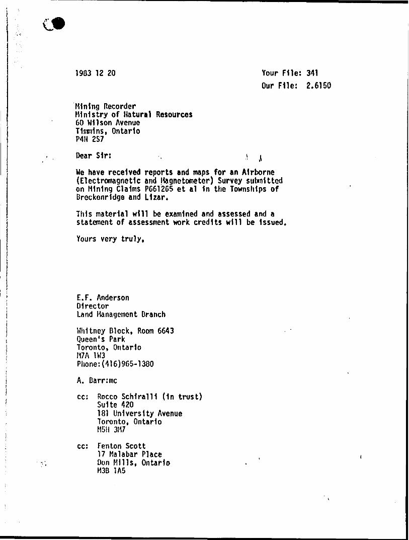
1903 12 20 Your File:Our File: 2.6150
Mining RecorderMinistry of Natural Resources60 Wilson AvenueTimmins, OntarioP4H 2S7
Dear Sir: , i j
We have received reports and maps for an Airborne (Electromagnetic and Magnetometer) Survey submitted on Mining Claims P6612C5 et al In the Townships of Breckenridge and Lizar.
This material will be examined and assessed and a statement of assessment work credits will be Issued.
Yours very truly,
E.F. AndersonDirectorLand Management Branch
Whitney Block, Room 6643 Queen's Park Toronto, Ontario M7A 1W3 Phone:(416)965-1380
A. Barrimc
cc: Rocco SchlralU (1n trust) Suite 420181 University Avenue Toronto, Ontario M5H 3M7
cc: Fenton Scott 17 Malabar Place Don Mills, Ontario M3B 1A5
Ministry ol Natural
Ontario
GeotechnicalReportApproval
FM*
Mining Lands Comments
/
To: Geophysics^ g ̂
Commenti
l D'tjy1 /a* Slgnature^-^ ^-—^ j*^Approved LJ With to la* again with corrections J ^jf /J s fff /^^^ 'S f r—————————————..——--——.——————...——.———^-—————1X7' ~ ___________ jfxC X J o.^Cc^Q
To: Geology - Expenditures *^
Date " ~ ——— g]gnttur( Q Approved Q With to tea again with correctioni
To: Geochemistry
Commentt
Approved With *o lea again with corractioniData Signature
[ JTo: Mining Lands Section, Room 6462, Whitney Block. (Tel: 5-1380)
MAP (5)?S -DO 17 4I
//x/GttftWUEL /W
C
dh-
co oenxCLO LU
(D
FO LJCLCOOtrCL
^̂*
Ul^IV \
' Q r, t
2 "~ Ns,W .J \0 CO 0- UJ ^ ^
w o: 5\^2 ^ -1 Y\0 0 0 \ x^ CO tt \
S UJ UJ o Or > o:
0 5 gtt ^" ^li O w 0
5 S3UJ ^ LU•J i sE
w u zZ ^K L?0 Q.CD
^S!1?l\
0)
OJEo ^
01
ia x
l1
p^O
COk rj-j"
— o-
SCALE
^j
1ro00O)
JZoi— o^
o
LJ
Q
LJ.CM
a cvj^J"
o
(0
U
^
o z:CL
QKi
1^
x J "H*goKUJ
"O O O Qro cvj —
•f,t m ''Ptqj&^fiif? ,^j**C;*'. - W"'^wf? ,;/^:* ™
Related Documents