UC-NRLF 75 CENTS B 3 Dia BOLT, NUT AND RIVET FORGING BY DOUGLAS T. HAMILTON MACHINERY'S REFERENCE BOOR NO. 113 PUBLISHED BY MACHINERY, NEW YORK

Welcome message from author
This document is posted to help you gain knowledge. Please leave a comment to let me know what you think about it! Share it to your friends and learn new things together.
Transcript
UC-NRLF 75 CENTS
B 3 Dia
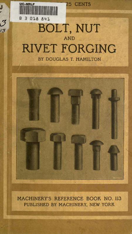
BOLT, NUTAND
RIVET FORGINGBY DOUGLAS T. HAMILTON
MACHINERY'S REFERENCE BOOR NO. 113
PUBLISHED BY MACHINERY, NEW YORK


MACHINERY'S REFERENCE SERIESEACH NUMBER IS ONE UNIT IN A COMPLETE LIBRARY OF
MACHINE DESIGN AND SHOP PRACTICE REVISED ANDREPUBLISHED FROM MACHINERY
NUMBER 113
BOLT, NUTAND
RIVET FORGINGBy DOUGLAS T. HAMILTON
CONTENTS
Bolt Heading Machines r - - - - - - -3Continuous-Motion Bolt and Rivet Headers - - - -20
Nut Forging Machines - - -- - - - -31
Copyright, 1914, The Industrial Press, Publishers of .MACHINERY,1-10-148 Lafayette Street, New York City
:
; ;/ ;
A^
CHAPTER I
BOLT HEADING MACHINES
The bolt and nut industry in America started in a very small way in
Marion, Conn., in 1818. In that year Micah Rugg, a country black-
smith, made bolts by the forging process. The first machine used for
this purpose was a device known as a heading block, which wasoperated by a foot treadle and a connecting lever. The connectinglever held the blank while it was being driven down into the im-
pression in the heading block by a hammer. The square iron fromwhich the bolt was made was first rounded, so that it could be ad-
mitted into the block. At first Rugg only made bolts to order, and
charged at the rate of sixteen cents a piece. This industry developed
very slowly until 1839, when Rugg went into partnership with Martin
Barnes; together they built the first exclusive bolt and nut factoryin the United States in Marion, Conn. The bolt and nut industrywas started in England in 1838 by Thomas Oliver, of Darlston, Staf-
fordshire. His machine was built on a somewhat different plan fromthat of Rugg's, but no doubt was a further development of the first
machine; Oliver's machine was known as the "English Oliver."
As is generally the case with a new industry, the methods and ma-chines used were very carefully guarded from the public, and this
characteristic seems to have followed this industry down to the pres-
ent time, judging by the scarcity of information available on the
subject. Some idea of the methods which were at first employed to
retain all information in the factory in which it was originated is well
brought out by the following instance: In 1842, when the industrywas beginning to be generally known, it is stated that a Mr. Clark,who at that time owned a bolt and nut factory in New England, andhad devised a special machine for use in this manufacture, had his
forging machine located in a room separated from the furnaces by athick wall. A hole was cut through this wall, and the man whooperated the machine received the heated bars from the furnace
through the small hole in the wall. The only person who ever got aglimpse of the machine was the operator. The forge man was not
permitted to enter the room.
Machine forging, as we know it to-day, is of wide application, em-bracing a large number of machines and processes that apply, in ameasure, to almost any manufacturing plant. Machine parts hitherto
made from castings are now made much more economically by theuse of the drop-hammer or forging machine, and give much moresatisfactory service.
Types of Machines
Upsetting and heading machines are divided into two general classes,
namely, stop-motion and continuous-motion headers. The stop-motion
347579
NO, UNBOLT, NUT AND RIVET FORGING
BOLT HEADING MACHINES . 5
headers have the greatest range, and are primarily used for headingbolts and for all kinds of upset forgings. The continuous-motion
headers are used only for heading rivets, carriage bolts and short
lengths of hexagon- and square-head machine bolts; they produce these
parts at a much faster rate than is possible with a stop-motion header,
but their range of work is limited. The universal practice is to shear
the bars cold when working a stop-motion header, and only in special
cases, when the shank of the headed piece is very short, is the side
shear used.
Rivets, etc., forged in the continuous-motion header, are made by the
process known as "off the bar;" that is, a bar is heated for a distance
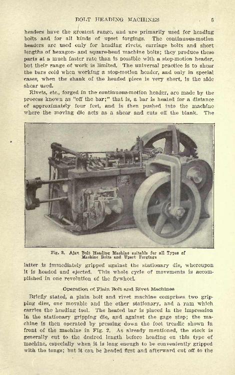
of approximately four feet, and is then pushed into the machinewhere the moving die acts as a shear and cuts off the blank. The
Fig. 2. Ajax Bolt Heading Machine suitable for all Types ofMachine Bolts and Upset Forgings
latter is immediately gripped against the stationary die, whereuponit is headed and ejected. This whole cycle of movements is accom-
plished in one revolution of the flywheel.
Operation of Plain Bolt and Rivet Machines
Briefly stated, a plain bolt and rivet machine comprises two grip-
ping dies, one movable and the other stationary, and a ram whichcarries the heading tool. The heated bar is placed in the impressionin the stationary gripping die, and against the gage stop; the ma-chine is then operated by pressing down the foot treadle shown in
front of the machine in Fig. 2. As already mentioned, the stock is
generally cut to the desired length before heading on this type of
machine, especially when it is long enough to be conveniently grippedwith the tongs; but it can be headed first and afterward cut off to the
NO. 113 BOLT, NUT AND RIVET FORGING
desired length in the side shear. It is also possible, in some makesof machines, to insert a cutting tool to cut off the blank before head-
ing, when the work is not greater in length than the capacity of the
machine.
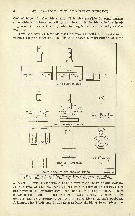
There are several methods used in making bolts and rivets in a
regular forging machine. In Fig. 3 is shown a diagrammatical view
MOVABLEDIE
STATIONARYDIE
|a
BOLT HEADING MACHINES
8 NO. 113 BOLT, NUT AND RIVET FORGING
bolt, and the shape of the head depends to a large extent on the skill
of the operator. The wide range of work, however, which can be
handled in dies of this type, makes them of almost universal applica-
tion, especially in a railroad shop.
Fig. 4 shows a set of single-blow rivet dies which are used in a
continuous-motion rivet header, and illustrates how these dies are
operated in the making of a rivet in one blow. The heated stock is
fed in and cut off to the exact length by a shear A; it is gripped
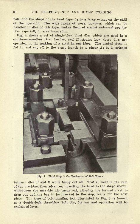
Third Step in the Production of Bolt Heads
between dies B and C while being cut off. Tool D, held in the ramof the machine, then advances, upsetting the head to the shape shown,
whereupon the movable die backs out, allowing the formed rivet to
drop out and the bar to be inserted to the stop, ready for the next
piece. The type of bolt heading tool illustrated in Fig. 5 is knownas a double-deck three-blow bolt die; its use and operation will be
explained later.
BOLT HEADING MACHINES 9
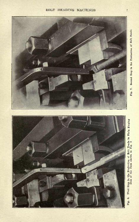
Successive Steps in Heading- Bolts
Figs. 6, 7 and 8 show the successive steps followed in the forging
of a hexagon-head bolt in the type of bolt forging dies illustrated
in Fig. 3. Bar A, which is heated for a portion of its length, is
placed in the impression in the stationary gripping die B, as shownin Fig. 6, and is gaged to length by the lifting stop C. The machineis then operated, and the movable die D closes in on the bar, gripping
it rigidly. The stop now rises, and, as the ram of the machine ad-
vances, the plunger E upsets the end of the bolt, the blocks F and Gforming a flat on each side of the upset end. The operator keeps his
foot on the treadle, and as the movable die backs out, he rotates the
rod one-sixth of a turn. This operation is repeated until the head
has been correctly formed. The operator now removes his foot from
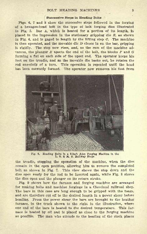
Fig. 9. Heading Bolts in a 2-inch Ajax Forging Machine in theL. S. & M. 8. Hallway Shops
the treadle, stopping the operation of the machine, when the dies
remain in the open position, allowing him to remove the completedbolt as shown in Fig. 7. This view shows the stop down and the
dies open ready for the rod to be inserted again, while Fig. 8 showsthe dies open and the plunger on its return stroke.
Fig. 9 shows how the furnace and forging machine are arrangedfor making bolts and machine forgings in a Cleveland railroad shop.
The bars in this case are long enough to be gripped with the tongs,
and are therefore cut off to the desired length in a power shear before
heading. From the power shear the bars are brought to the heating
furnace, in the truck shown to the right in the illustration, whereone end of the bars is heated to the desired temperature. This fur-
nace is heated by oil and is placed as close to the forging machineas possible. The man who attends to the heating of the stock places
10 NO. 113 BOLT, NUT AND RIVET FORGING
the rods in a row, and as soon as the end 10 be headed reaches the
proper temperature, he quickly removes the heated bar and passes
it to the forging machine operator, who immediately places it between
the dies, operates the machine, and forms the head. In this particular
example the bolt is l 1^ inch in diameter by 12 inches long, and is
formed in three blows in double-deck dies of the type illustrated in
Fig. 11. The dies and heading tool are kept cold by means of a
constant stream of water. As soon as the bolt is headed it is thrown
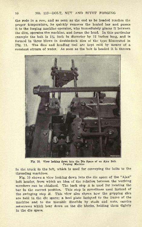
Fig. 10. View looking down into the Die Space of an Ajax Bolt
Forging Machine
in the truck to the left, which is used for conveying the bolts to the
threading machines.
Fig. 10 shows a view looking down into the die space of the "Ajax"
bolt header, from which an idea of the relation between the working
members can be obtained. The back stop A is used for locating the
bar in the correct position. This stop is sometimes used instead of
the swinging stop B. This view also shows how the gripping dies
are held in the die space; a heel plate fastened to the frame of the
machine and to the movable die-slide by studs and nuts, carries
set-screws which bear down on the die blocks, holding them tightly
in the die space.
BOLT HEADING MACHINES 11
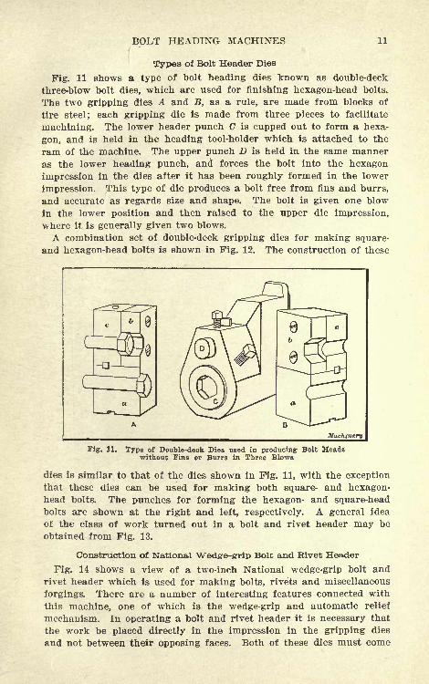
Types of Bolt Header Dies
Fig. 11 shows a type of bolt heading dies known as double-deck
three-blow bolt dies, which are used for finishing hexagon-head bolts.
The two gripping dies A and B, as a rule, are made from blocks of
tire steel; each gripping die is made from three pieces to facilitate
machining. The lower header punch C is cupped out to form a hexa-
gon, and is held in the heading tool-holder which is attached to the
ram of the machine. The upper punch D is held in the same manner
as the lower heading punch, and forces the bolt into the hexagon
impression in the dies after it has been roughly formed in the lower
impression. This type of die produces a bolt free from fins and burrs,
and accurate as regards size and shape. The bolt is given one blow
in the lower position and then raised to the upper die impression,
where it is generally given two blows.
A combination set of double-deck gripping dies for making square-
and hexagon-head bolts is shown in Fig. 12. The construction of these
Fig. 11. Type of Double-deck Dies used in producing Bolt Headswithout Fins or Burrs in Three Blows
dies is similar to that of the dies shown in Fig. 11, with the exception
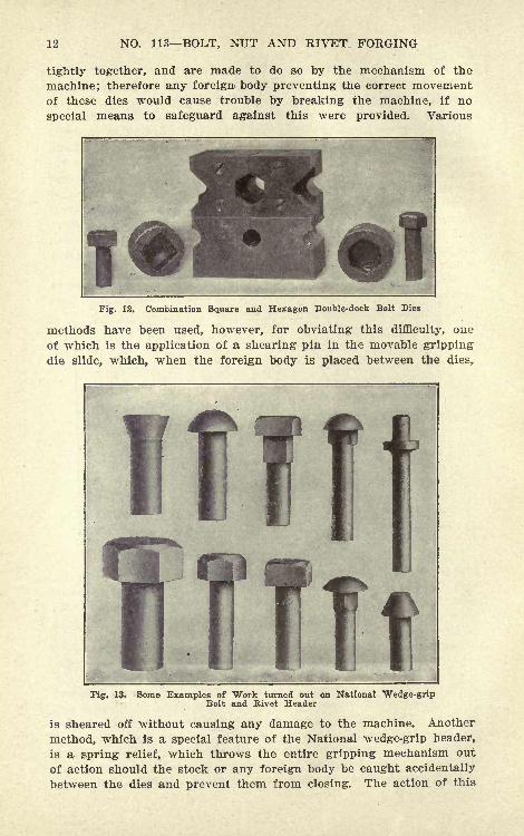
that these dies can be used for making both square- and hexagon-head bolts. The punches for forming the hexagon- and square-headbolts are shown at the right and left, respectively. A general idea
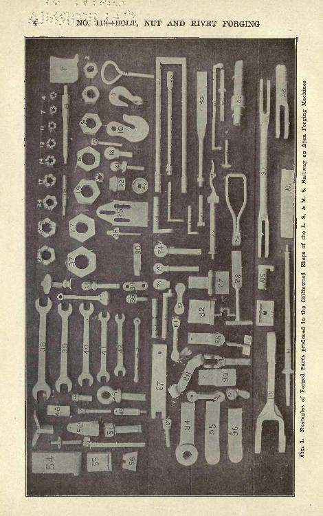
of the class of work turned out in a bolt and rivet header may be
obtained from Fig. 13.
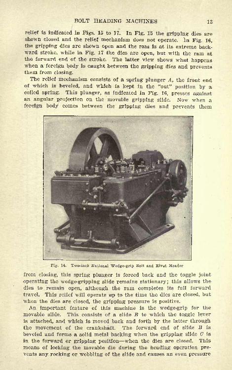
Construction of National Wed&e-grrip Bolt and Rivet Header
Fig. 14 shows a view of a two-inch National wedge-grip bolt and
rivet header which is used for making bolts, rivets and miscellaneous
forgings. There are a number of interesting features connected with
this machine, one of which is the wedge-grip and automatic relief
mechanism. In operating a bolt and rivet header it is necessary that
the work be placed directly in the impression in the gripping dies
and not between their opposing faces. Both of these dies must come
12 NO. 113 BOLT, NUT AND RIVET FORGING
tightly together, and are made to do so by the mechanism of the
machine; therefore any foreign- body preventing the correct movementof these dies would cause trouble by breaking the machine, if no
special means to safeguard against this were provided. Various
Fig. 12, Combination Square and Hexagon Double-deck Bolt Dies
methods have been used, however, for obviating this difficulty, one
of which is the application of a shearing pin in the movable gripping
die slide, which, when the foreign body is placed between the dies,
Fig. 13. Some Examples of Work turned out on National Wedge-gripBolt and Rivet Header
is sheared off without causing any damage to the machine. Another
method, which is a special feature of the National wedge-grip header,
is a spring relief, which throws the entire gripping mechanism out
of action should the stock or any foreign body be caught accidentally
between the dies and prevent them from closing. The action of this
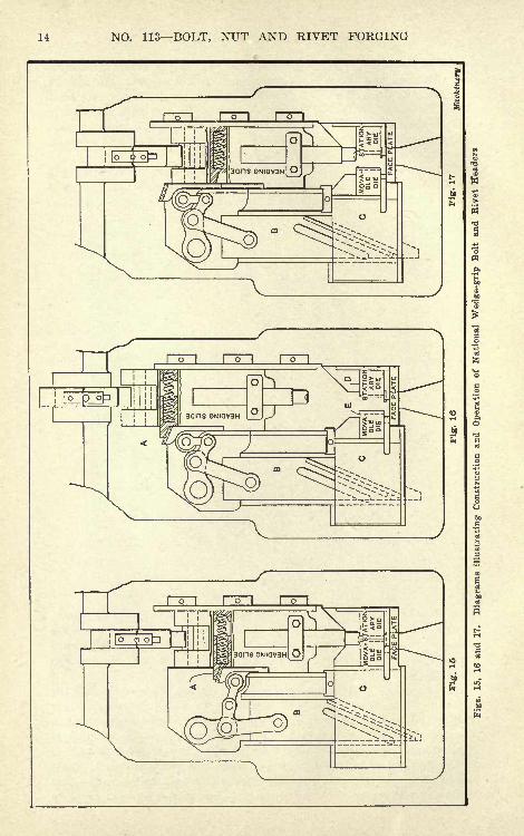
BOLT HEADING MACHINES 13
relief is indicated in Figs. 15 to 17. In Fig. 15 the gripping dies areshown closed and the relief mechanism does not operate, in Fig. 16,the gripping dies are shown open and the rani is at its extreme back-ward stroke, while in Fig. 17 the dies are open, but with the ram atthe forward end of the stroke. The latter view shows what happenswhen a foreign body is caught between the gripping dies and preventsthem from closing.
The relief mechanism consists of a spring plunger A, the front endof which is beveled, and which is kept in the "out" position by acoiled spring. This plunger, as indicated in Fig. 16, presses againstan angular projection on the movable gripping slide. Now when aforeign body comes between the gripping dies and prevents them
Fig. 14. Two-inch National Wedge-grip Bolt and Rivet Header
from closing, this spring plunger is forced back and the toggle joint
operating the wedge-gripping slide remains stationary; this allows the
dies to remain open, although the ram completes its full forward
travel. This relief will operate up to the time the dies are closed, but
when the dies are closed, the gripping pressure is positive.
An important feature of this machine is the wedge-grip for the
movable slide. This consists of a slide B to which the toggle lever
is attached, and which is moved back and forth by the latter throughthe movement of the crankshaft. The forward end of slide B is
beveled and forms a solid metal backing when the gripping slide C is
in the forward or gripping position when the dies are closed. This
means of locking the movable die during the heading operation pre-
vents any rocking or wobbling of the slide and causes an even pressure
14 NO. 113 BOLT, NUT AND RIVET FORGING
BOLT HEADING MACHINES 15
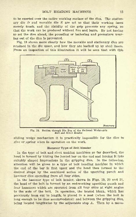
to be exerted over the entire working surface of the dies. The station-
ary die D and movable die E are set so that their working faces
merely touch, and the rigidity of the grip prevents any spring, so
that the work can be produced without fins and burrs. By not havingto set the dies ahead, the pounding or battering and premature wear-
ing out of the dies is prevented.
Fig. 18 shows more clearly how the movable and stationary dies are
retained in the die space, and how they are backed up by steel liners.
From an inspection of this illustration it will be seen that with this
WlMachinery
Fig. 18. Section through Die Box of the National Wedge-gripBolt and Rivet Header
sliding wedge mechanism it is practically impossible for the dies to
give or .spring when in operation on the work.
Hammer Type of Bolt Header
In the type of bolt and rivet making machines so far described, the
head is formed by hitting the heated bar on the end and forcing it into
suitably shaped impressions in the gripping dies. In the following,
attention will be given to a type of bolt heading machine in which
the end of the bar is first upset and the head then formed to the
desired shape by the combined action of the upsetting punch and
hammer dies operating from all four sides.
In the hammer type of bolt header, shown in Figs. 19, 20 and 21,
the head of the bolt is formed by an end-working upsetting punch and
four hammers which are operated from all four sides at right angles
to the axis of the bolt. In operation, the heated blank, which has
previously been cut to length, is placed in a seat (when the bolt is
long enough to be thus accommodated) and between the gripping dies,
being located lengthwise by the adjustable stop A. Then by a move-
16 NO. 113 BOLT, NUT AND RIVET FORGING
ment of the hand-lever C, the dies (one of which is shown at B in
Fig. 21) are closed and the machine is started. The stock is not
moved during the forging operation, but is kept up against the adjust-
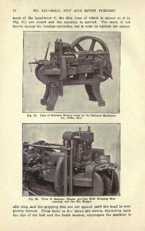
Fig-. 19. Type of Hammer Header made by the National MachineryCo., Tiffin, Ohio
Fig. 20. View of Hammer Header showing Both Gripping Dies
removed, and One Die Hanger
able stop, and the gripping dies are not opened until the head is com-
pletely formed. From three to five blows are struck, depending upon
the size of the bolt and the finish desired, whereupon the machine is
BOLT HEADING MACHINES 17
stopped and the dies are opened by operating the hand-lever, allowingthe finished work to drop from the machine. The side-forming ham-mers D, Fig. 20, give two blows to every blow struck by the head-
ing tool E and the vertical hammers F.
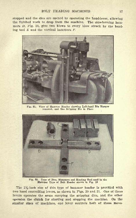
Fig. 21. View of Hammer Header showing Left-hand Die Hangerremoved, and One Gripping Die in Place
Fig. 22. Type of Dies, Hammers and Heading Tool used in theHammer Type of Bolt Header shown in Fig. 19
The 1%-inch size of this type of hammer header is provided with
two hand controlling levers, as shown in Figs. 20 and 21. One of these
levers operates the arms carrying the gripping dies, and the other
operates the clutch for starting and stopping the machine. On the
smaller sizes of machines, one lever controls both of these move-
18 NO. 113 BOLT, NUT AND RIVET FORGING
ments. Fig. 20 shows one of these hammer headers with the grip-
ping dies and the left-hand gripping die hanger removed; this view
also shows clearly the upsetting punch and the four forming ham-
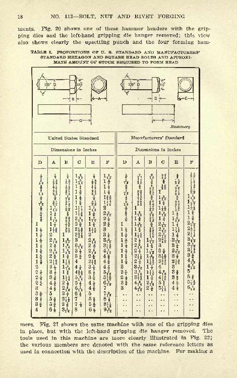
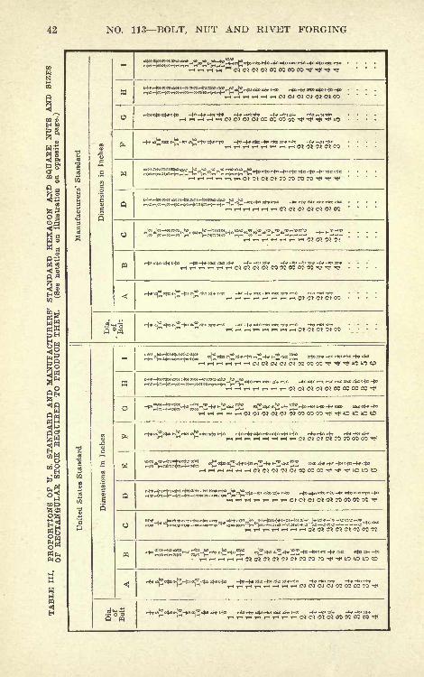
TABLBJ I. PROPORTIONS OF U. S. STANDARD AND MANUFACTURERS'STANDARD HEXAGON AND SQUARE HEAD BOLTS AND APPROXI-
MATE AMOUNT OF STOCK REQUIRED TO FORM HEAD
A<
y
ft
ft
f
1
HliifHif
2
at
3
3t
=qK c
*jp F
Machinery
United States Standard
Dimensions in Inches
H
itHI
ifat
at
21
It
*h
3f4
il
it
IIf
J
ri
.t2H8t8t314i4f5
6|5f
itItIf
at
I*8t3ft
4ft4f4f41
?*
st?H
Manufacturers' Standard
Dimensions in Inches
ft
iy6
f
i!ifIf
5*
2*
ii
1
it
itni
s1
li
45
5$
li
H
3
8t3H3^- 3
43 *
4ft4H6f
E
il
?II
i?
it
-2ftat
3
3f8*
iiH
Iif
jjfl
4*4ft
mers. Fig. 21 shows the same machine with one of the gripping dies
in place, but with the left-hand gripping die hanger removed. The
tools used in this machine are more clearly illustrated in Fig. 22;
the various members are denoted with the same reference letters as
used in connection with the description of the machine. For making a

BOLT HEADING MACHINES 19
square-headed bolt, the side-working hammers, of course, are of the
same shape as the vertical hammers.The type of hammer header illustrated in Figs. 19, 20 and 21 is
limited in its scope to the production of square, hexagon and tee-
headed bolts as shown in Fig. 23. These, however, can be producedin large quantities at a low cost, and what is more important, the
product is entirely free from fins and burrs, and is shaped as ac-
curately as is possible by the forging method. The fact, however,that it takes longer to change the dies from one size to another in this
type of machine militates against its installation in preference to the
Fig. 23. Some Examples of Work produced in National Hammer Headers
other types of bolt headers, where frequent changes in the sizes of
dies are necessary.
Stock Required for Bolt Heads
In forming a head on a bolt or rivet, the heated metal on the end
of the bar is upset or formed into the desired shape by a plunger held
in the ram of the forging machine. To produce the head requires con-
siderably more metal than the thickness of the head because of the
increase in diameter and hence it is necessary to allow a certain
amount of excess stock to form the head. Table I gives proportions
of U. S. standard and Manufacturers' standard hexagon and square
bolt heads, and also the approximate amount of stock required to
form the head this information being listed in Columns "C" and
"F." The excess amount of stock given is not exact, but is close
enough for starting the machine, as the stop can afterward be ad-
justed to suit.
CHAPTER II
CONTINUOUS-MOTION BOLT AND RIVET HEADERS
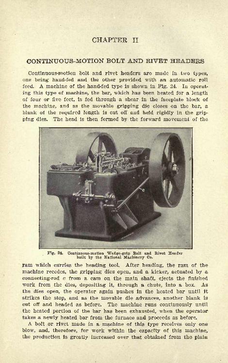
Continuous-motion bolt and rivet headers are made in two types,
one being hand-fed and the other provided with an automatic roll
feed. A machine of the hand-fed type is shown in Fig. 24. In operat-
ing this type of machine, the bar, which has been heated for a lengthof four or five feet, is fed through a shear in the faceplate block of
the machine, and as the movable gripping die closes on the bar, ablank of the required length is cut off and held rigidly in the grip-
ping dies. The head is then formed by the forward movement of the
Fig. 24. Continuous-motion Wedge-grip Bolt and Rivet Headerbuilt by the National Machinery Co.
ram which carries the heading tool. After heading, the ram of the
machine recedes, the gripping dies open, and a kicker, actuated by a
connecting-rod c from a cam on the main shaft, ejects the finished
work from the dies, depositing it, through a chute, into a box. Asthe dies open, the operator again pushes in the heated bar until it
strikes the stop, and as the movable die advances, another blank is
cut off and headed as before. The machine runs continuously until
the heated portion of the bar has been exhausted, when the operatortakes a newly heated bar from the furnace and proceeds as before.
A bolt or rivet made in a machine of this type receives only one
blow, and, therefore, for work within the capacity of this machine,the production is greatly increased over that obtained from the plain
BOLT AND RIVET HEADERS 21
type of forging machine. One of the chief requisites in a machine of
the continuous-motion type is that of securing a rigid grip on the
work while the head is being formed. If the grip is not satisfactory,
that is, if the dies separate, it causes the shank of the bolt or rivet
to become tapered or out of round, and also results in fins being
produced on the shank and under the head. Furthermore, unless the
machine is provided with suitable slides which can be kept in proper
alignment, it is difficult to secure work on which the heads are cen-
trally located with the shanks, and also to keep the shear and movable
die in correct working relation.
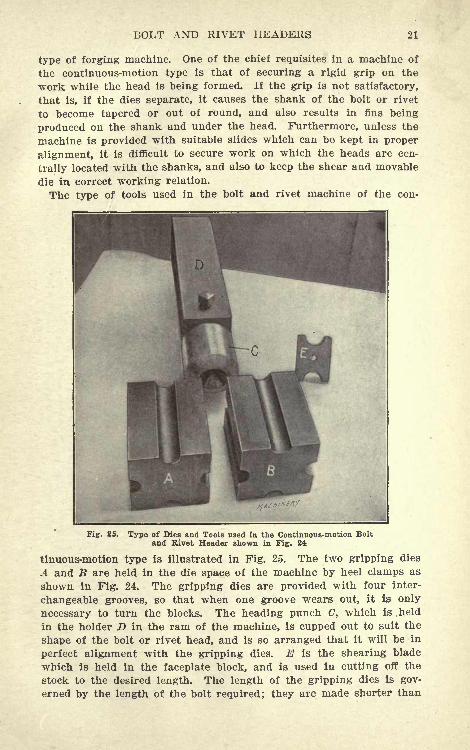
The type of tools used in the bolt and rivet machine of the con-
Fig. 25. Type of Dies and Tools used in the Continuous-motion Bolt
and Rivet Header shown in Fig. 24
tinuous-motion type is illustrated in Fig. 25. The two gripping dies
A and B are held in the die space of the machine by heel clamps as
shown in Fig. 24. The gripping dies are provided with four inter-
changeable grooves, so that when one groove wears out, it is only
necessary to turn the blocks. The heading punch C, which is. held
in the holder D in the ram of the machine, is cupped out to suit the
shape of the bolt or rivet head, and is so arranged that it will be in
perfect alignment with the gripping dies. E is the shearing blade
which is held in the faceplate block, and is used in cutting off the
stock to the desired length. The length of the gripping dies is gov-
erned by the length of the bolt required; they are made shorter than
22 NO. 113 BOLT, NUT AND RIVET FORGING
the blank from which the bolt is made, thus allowing for sufficient
extra stock to form the head.
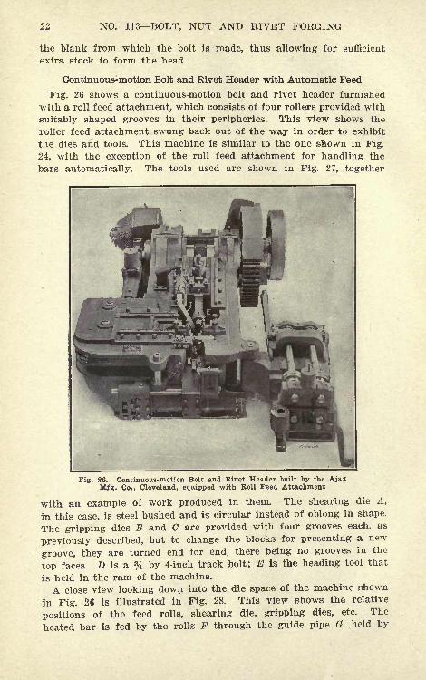
Continuous-motion Bolt and Rivet Header with Automatic Feed
Fig. 26 shows a continuous-motion bolt and rivet header furnished
with a roll feed attachment, which consists of four rollers provided with
suitably shaped grooves in their peripheries. This view shows the
roller feed attachment swung back out of the way in order to exhibit
the dies and tools. This machine is similar to the one shown in Fig.
24, with the exception of the roll feed attachment for handling the
bars automatically. The tools used are shown in Fig. 27, together
Fig. 26. Continuous-motion Bolt and Rivet Header built by the AjaxMfg. Co., Cleveland, equipped with Roll Feed Attachment
with an example of work produced in them. The shearing die A,
in this case, is steel bushed and is circular instead of oblong in shape.
The gripping dies B and C are provided with four grooves each, as
previously described, but to change the blocks for presenting a new
groove, they are turned end for end, there being no grooves in the
top faces. D is a % by 4-inch track bolt; E is the heading tool that
is held in the ram of the machine.
A close view looking down into the die space of the machine shown
in Fig. 26 is illustrated in Fig. 28. This view shows the relative
positions of the feed rolls, shearing die, gripping dies, etc. The
heated bar is fed by the rolls F through the guide pipe G, held by
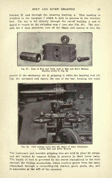
BOLT AND RIVET HEADERS 23
bracket H, and through the shearing bushing A. This bushing is
retained in the faceplate / which is held in grooves in the machine
bed. The bar is fed directly through the cut-off bushing A and is
gaged to length by the swinging stop J (see also Fig. 26). The mov-
able die C then advances, cuts off the blank and carries it into the
Fig. 27. Type of Dies and Tools used in Bolt and Rivet MakingMachine shown in Fig. 26
groove in the stationary die B, gripping it while the heading tool (E,
Fgi. 26) advances and upsets the end of the bar, forming the head.
Fig. 28. View looking down into Die Space of Ajax Continuous-motion Bolt and Rivet Header
The stationary and movable gripping dies are held in place by straps,
and are located by tongues fitting in grooves in their lower faces.
The length of feed is governed by the travel transmitted to the rolls
through the feeding mechanism, which receives power from the maincrankshaft through a connecting-rod, ratchet, pawl, gears, etc., andis adjustable at the will of the operator.
NO. 113 BOLT, NUT AND RIVET FORGING
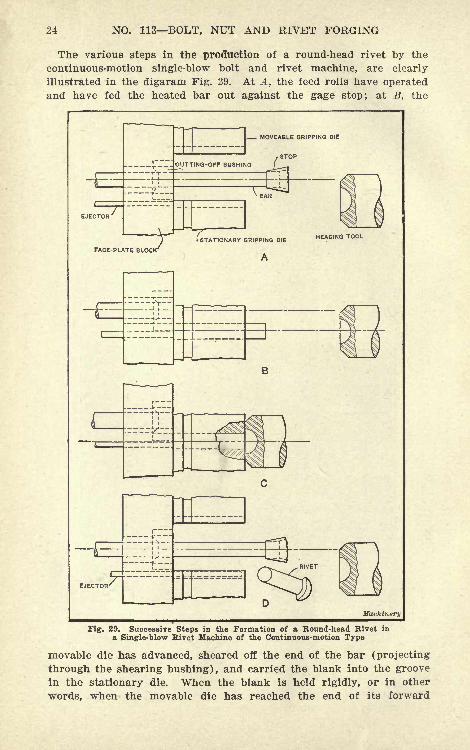
The various steps in the production of a round-head rivet by the
continuous-motion single-blow bolt and rivet machine, are clearly
illustrated in the digaram Fig. 29. At A, the feed rolls have operated
and have fed the heated bar out against the gage stop; at B, the
MOVEABLE GRIPPING DIE
STOP
FACE-PLATE BLOCK
(STATIONARY GRIPPING DIE
A
HEADING TOOL
Machinery
Fig. 29. Successive Steps in the Formation of a Round-head Rivet in
a Single-blow Rivet Machine of the Continuous-motion Type
movable die has advanced, sheared off the end of the bar (projecting
through the shearing bushing), and carried the blank into the groove
in the stationary die. When the blank is held rigidly, or in other
words, when the movable die has reached the end of its forward
BOLT AND RIVET HEADERS 25
movement, the heading tool advances, as shown at C, and upsets theend of the bar, forming the head. At D, the movable die and headingtool have retreated, the ejector pin (see K, Pig. 26) has advanced,pushing out the completed rivet, and the bar has been fed out againready for a repetition of the operations.
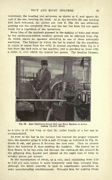
Some idea of the methods pursued in the making of bolts and rivets
by the continuous-motion machine process can be obtained from Pig.
30, which shows an operator attending to one of these automaticmachines. The furnace in which the bar is heated (in the conditionin which it comes from the mill) is located anywhere from 3^ to 4
feet from the feed rolls of the machine, and is provided in front witha roller A, over which the heated bar passes. The heating furnace,
Fig. 30. Ajax Continuous-motion Bolt and Rivet Machine in Actionmaking 1%-inch Rivets
as a rule, is 30 feet long, so that the entire length of a bar can be
accommodated.As soon as the bar in the furnace has reached the proper tempera-
ture, the operator grips it with a pair of tongs, as indicated in Pig. 30,
draws it out, and places it between the feed rolls. Then he presses
down the foot-lever B, thus starting the machine. The heated bar is
then drawn in by the rolls, fed through the cutting-off die, gripped in
the gripping dies, headed and ejected at the rapid rate of forty to
seventy pieces per minute.
In the manufacture of rivets, as a rule, steel containing from 0.10
to 0.12 per cent carbon is more frequently used than wrought iron,
although the latter material is used in considerable quantities in
some manufacturing establishments. Wrought iron for making rivets
26 NO. 113 BOLT, NUT AND RIVET FORGING
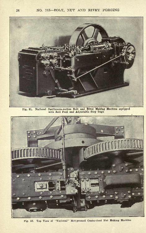
Fig. 31. National Continuous-motion Bolt and Rivet Making Machine equippedwith Roll Feed and Adjustable Stop Gage
Fig. 32. Top View of "National" Hot-pressed Center-feed Nut Making Machine
BOLT AND RIVET HEADERS 27
is heated to almost a white heat, but steel which contains from 0.10
to 0.12 per cent carbon is heated to only about 1400 degrees F. abright red color. When the head of a rivet is so shaped that it is
necessary to carry the stock down far into the heading tool, the tem-
perature to which the bar is heated must be increased, in order to
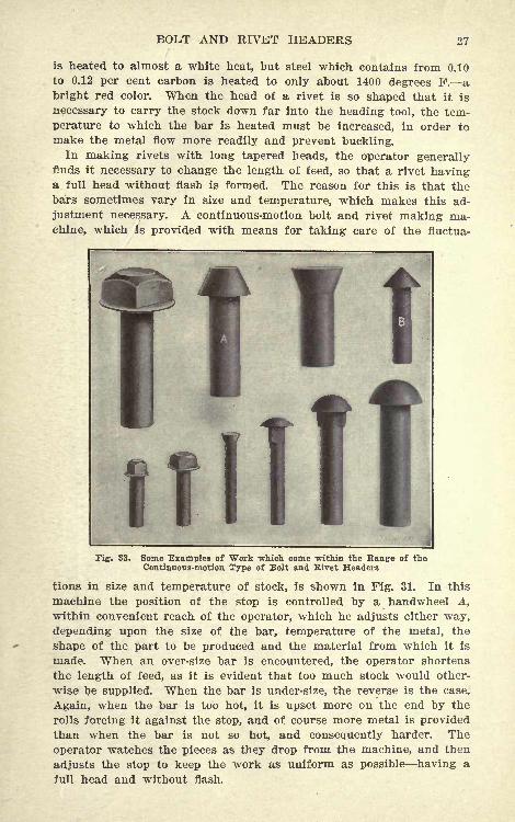
make the metal flow more readily and prevent buckling.In making rivets with long tapered heads, the operator generally
finds it necessary to change the length of feed, so that a rivet havinga full head without flash is formed. The reason for this is that the
bars sometimes vary in size and temperature, which makes this ad-
justment necessary. A continuous-motion bolt and rivet making ma-chine, which is provided with means for taking care of the fluctua-
Fig. 33. Some Examples of Work which come within the Range of theContinuous-motion Type of Bolt and Rivet Headers
tions in size and temperature of stock, is shown in Fig. 31. In this
machine the position of the stop is controlled by a handwheel A,
within convenient reach of the operator, which he adjusts either way,
depending upon the size of the bar, temperature of the metal, the
shape of the part to be produced and the material from which it is
made. When an over-size bar is encountered, the operator shortens
the length of feed, as it is evident that too much stock would other-
wise be supplied. When the bar is under-size, the reverse is the case.
Again, when the bar is too hot, it is upset more on the end by the
rolls forcing it against the stop, and of course more metal is provided
than when the bar is not so hot, and consequently harder. The
operator watches the pieces as they drop from the machine, and then
adjusts the stop to keep the work as uniform as possible having afull head and without flash.
28 NO. 113 BOLT, NUT AND RIVET FORGING
The feed rolls in the machine shown in Fig. 31 are made of chilled
iron castings, and are kept cool by water jackets, insuring even tem-
perature and minimum wear. They are operated from the main-shaft
of the rolls. The movements of the machine are timed so as to allow
ment as shown, adjustable for securing variations in the feeding time
of the rolls. The movements of the machine are timed so as to allow
the gripping dies to remain open a comparatively large part of the
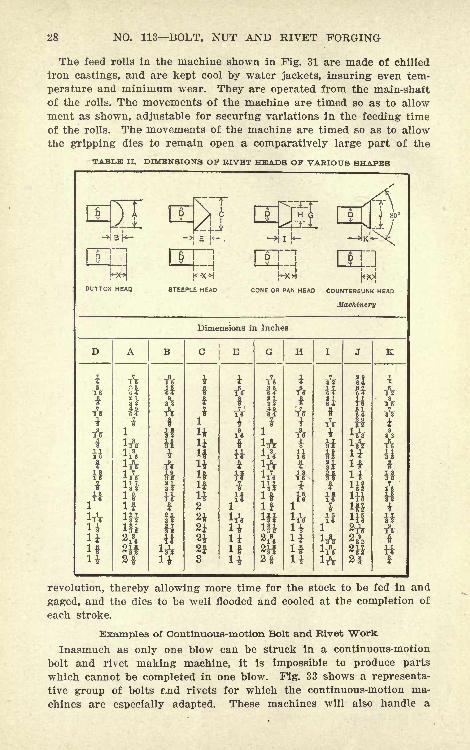
TABLE II. DIMENSIONS OF RIVET HEADS OF VARIOUS SHAPES
MCUTTCN HEAD. STEEPLE HEAD CONE OR PAN HEAD COUNTERSUNK HEAD
Machinery
Dimensions in InchesDABCEGHIiA&A
tif
i"
ftUifU
Asi
si
I!
i?Ji
i
i\
ifH^*
3
AfTV
I9.
H
i11
ItUifU
tAAf
Vif
1H
JAuifii
uifU
2f
-A
A
$AA
?
HT3*
f
revolution, thereby allowing more time for the stock to be fed in and
gaged, and the dies to be well flooded and cooled at the completion of
each stroke.
iples of Continuous-motion Bolt and Rivet Work
Inasmuch as only one blow can be struck in a continuous-motion
bolt and rivet making machine, it is impossible to produce parts
which cannot be completed in one blow. Fig. 33 shows a representa-
tive group of bolts rnd rivets for which the continuous-motion ma-
chines are especially adapted. These machines will also handle a
BOLT AND RIVET HEADERS 29
great variety of special work, such as square and hexagon head
single-blow bolts, track bolts, etc. The cone-shaped rivets A and Billustrate the point mentioned in a previous paragraph regarding the
difficulty encountered in producing work which is carried down far
into the heading tool. Of course, these are not by any means extreme
examples, but they serve to illustrate the poirt.
Making Bolt and Rivet Dies
Bolt dies which are used in a forging machine are as a rule madefrom steel containing from 0.60 to 0.80 per cent carbon, and are hard-
ened and drawn. The gripping dies are tempered hard, so that the
sharp corners on the edges of the dies will not wear away rapidly.
It is customary to harden these dies in either oil or water, and then
draw the temper so that a file will just take hold. The heading tool,
which is comparatively small in diameter, and is called upon to per-
form heavy duty, must be much tougher than the gripping dies. Or-
dinarily the heading tool is made from a tough steel containing from0.40 to 0.50 per cent carbon, and is drawn considerably more than the
gripping dies.
In making the impressions in the gripping dies for heading ordi-
nary sizes of bolts, no allowance is made for the shrinkage of the
metal. However, in drilling the hole in the dies which grip the stock
when it is being headed, a liner is placed between the two halves of
the die, so that when they come together on the stock, the latter will
be securely held. For dies with a ^4- to %-inch hole, a liner 1/64 inch
thick is placed between the opposing faces, when drilling the hole.
For holes larger than % inch and up to 1 inch, a liner 1/32 inch
thick is used; for holes from 1 inch up to 1^ inch in diameter, a
liner 3/64 inch thick is used; and from iy2 inch up to and including
3 inches in diameter, a liner 1/16 inch is employed. The double-
deck type of dies are made from six blocks of steel bolted and keyed
together to facilitate machining.In making bolt and rivet dies which are used in continuous-motion
machines, it is customary when making rivets from % to 1 inch in
diameter, to use bar stock which is rolled 1/64 "inch under-size. The
dies referred to are shown in Figs. 25 and 27. The holes in the
gripping dies are drilled to exact size (not 1/64 inch under-size, which
is the diameter of stock used), and the expansion of the iron in
heating gives sufficient grip, as it is only necessary to prevent the
rivets from being pulled out of the dies by the return stroke of the
heading tool. The reason for this is that in the continuous-motion
type of bolt and rivet machine, the work is supported on the sides
by the gripping dies, and is backed up by the shear, so that it is prac-
tically held in a box while the head is being formed. The same grade
of steel is used for making rivet tools as for making tools for produc-
ing bolts, and the heat-treatment is also carried on in a similar
manner.
30 NO. 113 BOLT, NUT AND RIVET FORGING
Stock Required for Rivet Heads
In making rivets in a continuous-motion rivet machine, the amountof excess stock (X, Table II) required is generally obtained by trial,
but when definite shapes and proportions of rivet heads have been
decided upon, the amount of excess stock required can be calculated
approximately. The great difficulty in giving tables covering the
amount of excess stock required is that no standard for rivet heads is
universally followed, with the result that a slight difference in the
curve or height of the head changes the amount of stock necessary.
In addition to this, the scale of the furnace, depending upon whether
gas, oil or coal is used for heating, so changes the amount of stock
required that a special setting of the stop in different cases is required.
This is one of the reasons why up-to-date continuous-motion rivet
making machines are provided with stops which can be adjusted
while the machine is in motion. It is evident, therefore, that the
exact amount of stock required is a question of some nicety, and it is
surprising to what extent even the scaling off in the furnace will
affect the stock required for the rivet head. What are considered in
some shops standard shapes and sizes for rivet heads are given in
Table II.
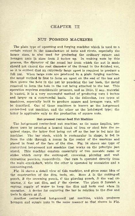
CHAPTER III
NUT FORGING MACHINES
The plain type of upsetting and forging machine which is used to acertain extent in the manufacture of bolts and rivets, especially the
larger sizes, is also Used for producing the ordinary square and
hexagon nuts in sizes from 2 inches up. In making nuts by this
process, the diameter of the round bar from which the nut is madeshould not exceed the root diameter of the thread in the finished nut,
so it is evident that an extremely large upset is required to produce a
full nut. When large nuts are produced in a plain forging machine,the usual method is first to form an upset on the end of the bar andthen pierce the hole in the nut by punching the bar back, the metal
removed to form the hole in the nut being attached to the bar. This
operation requires considerable pressure, and as little, if any, material
is wasted, it is a very successful method of producing nuts 2 inches
and larger on a commercial basis. In the following, two types of
machines, especially built to produce square and hexagon nuts, will
be described. One of these machines is known as the hot-pressed
center-feed nut machine, and the other as the hot-forged type; the
latter is applicable only to the production of square nuts.
Hot-pressed Center-feed Nut Machine
The hot-pressed center-feed nut machine, as its name implies, pro-
duces nuts by pressing a heated blank of iron or steel into the re-
quired shape, the latter first being cut off as the bar is fed into the
machine. The bar stock, which is rectangular in shape, is fed in
from the side through a recess in the center of the machine and
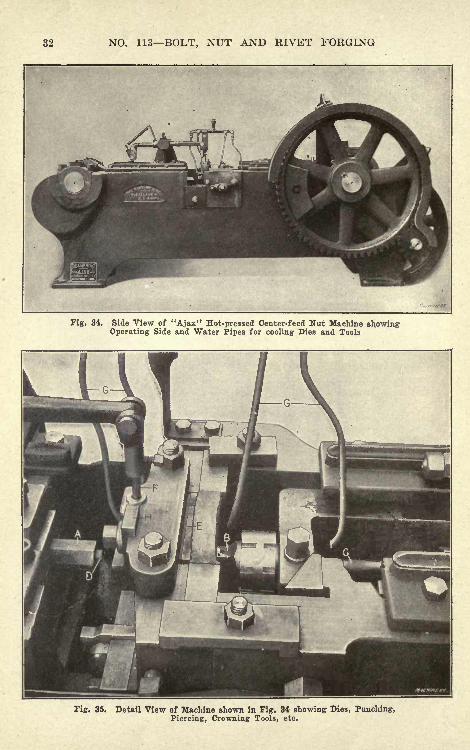
placed in front of the face of the dies. Fig. 34 shows one type of
center-feed hot-pressed nut machine that works on the principle just
stated. This machine consists essentially of two movable rams or
slides which carry the cutting-off, crowning, piercing and wad-
extracting punches, respectively. One ram is operated directly from
the main crankshaft, while the other is operated by eccentrics and a
connecting-rod.
.Fig. 35 shows a detail view of this machine, and gives some idea of
the construction of the dies, tools, etc. Here A is the cutting-off
punch, B the crowning punch, C the piercing punch, D the wad ex-
tractor, E the nut dies, and F the ejector. The pipes G furnish a
copious supply of water to keep the dies and tools cool when in
operation. A device for centering the bar in relation to the dies and
tools is shown at H.
Another center-feed hot-pressed nut machine, which produces
hexagon and square nuts in the same manner as that shown in Fig.
32 NO. 113 BOLT, NUT AND RIVET FORGING
Fig. 34, Side View of "Ajax" Hot-pressed Center-feed Nut Machine showingOperating Side and Water Pipes for cooling Dies and Tools
Fig. 35. Detail View of Machine shown in Fig. 34 showing Dies, Punching,Piercing, Crowning Tools, etc.
NUT FORGING MACHINES
34 is shown in Fig. 32. In this machine, however, both rams or slides
are operated directly from the source of power by a pinion and two
large gears, one gear driving each slide. The majority of manu-facturers produce nuts from a material known as soft, mild, open-
hearth steel, which has a comparatively fine grain, and consequently,
when forged, has less tendency to crack than does wrought iron. It
can also be threaded much easier and with a smoother finish than
wrought iron, owing to the fact that great difficulty is met with in
Machinery
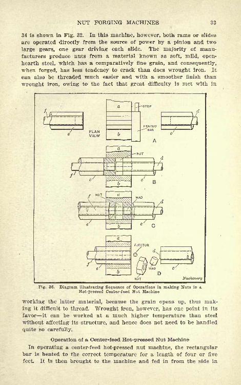
Fig. 3. Diagram illustrating Sequence of Operations in making Nuts in aHot-pressed Center-feed Nut Machine
working the latter material, because the grain opens up, thus mak-
ing it difficult to thread. Wrought iron, however, has one point in its
favor it can be worked at a much higher temperature than steel
without affecting its structure, and hence does not need to be handled
quite so carefully.
Operation of a Center-feed Hot-pressed Nut Machine
In operating a center-feed hot-pressed nut machine, the rectangularbar is heated to the correct temperature for a length of four or five
feet. It is then brought to the machine and fed in from the side in
34 NO. 113 BOLT, NUT AND RIVET FORGING
front of the face of the main dies, as indicated at A in Fig. 36. Thecut-off tool c then moves up and shears the blank from the end of the
bar, carries it into the main dies a and &, and presses it against the
crowning tool e, which has also advanced, as indicated at B. The
piercing tool / now advances, punches the hole in the nut, and carries
the wad into the cutting-off tool, as shown at (7; then the cutting-off
and piercing tools c and / recede, and the crowning tool e advances,
forcing the nut out of the dies. As the cut-off tool c recedes, the
extractor d forces the wad out of the punch at the same time as the
nut is ejected from the dies. The ejector, which is operated by a
lever and cam, as shown in Fig. 32, is provided to prevent the nut
from adhering to the crowning tool; this very seldom happens, how-
ever. A completed nut is produced at each revolution of the large
gears.
The operations just described are repeated until the heated portion
of the bar has been used up, after which the operator places the bar
in the furnace to be re-heated, takes a freshly heated bar from the
furnace, and proceeds as before. The machine is run continuously,
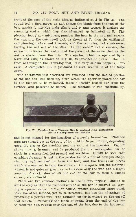
Fig. 37. Showing how a Hexagon Nut is produced from RectangularBar in a Hot-pressed Nut Machine
and is not stopped for the insertion of a newly heated bar. Finished
nuts are turned out at the rate of from 40 to 70 per minute, depending
upon the size of the machine and the skill of the operator. Fig. 37
shows how a hexagon nut is produced from a rectangular bar of
stock in a center-feed hot-pressed nut machine. It will be seen that
considerable scrap is lost in the production of a nut of hexagon shape,
viz., the wad removed to form the hole, and the triangular pieces
which are removed to form the corners. On a square nut the material
wasted is not quite so great, as in this case only the wad and a slight
amount of stock, sheared off the end of the bar to form a square
corner, are removed.
There are two common methods in use in nut forging. One is to
set the stop so that the rounded corner of the bar is sheared off, leav-
ing a square corner. This, of course, wastes somewhat more stock
than the other method, yet to be described, but has the advantage of
producing a perfect nut. The rounded corner is caused by the cut-off
tool which, in removing the block of metal from the end of the bar
to form the nut, rounds over the end of the bar, due to the hot metal
NUT FORGING MACHINES 35
drawing over, and thus makes this waste of stock necessary if a full-
shaped nut is to be secured.
Another method in common use to save stock and at the same time
produce a practically full nut, is to invert the bar after each stroke
of the machine. By this method opposite sides of the bar are alter-
nately presented to the dies, which overcomes, to a large extent, the
effect of the fin on one side and the rounded corner on the other, and
produces a full nut without shearing any material from the end of
the bar. The only objection to this method is the necessity of turn-
ing the bar, which, if heavy, soon tires the operator. On the larger
sizes of nuts, the first method is used, as the bars are quite heavy*
m
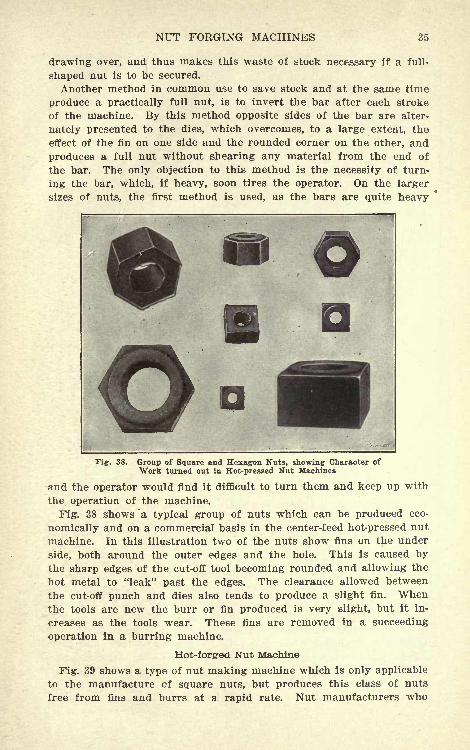
Fig. 38. Group of Square and Hexagon Nuts, showing Character of
Work turned out in Hot-pressed Nut Machines
and the operator would find it difficult to turn them and keep up with
the operation of the machine.
Fig. 38 shows "a typical group of nuts which can be produced eco-
nomically and on a commercial basis in the center-feed hot-pressed nut
machine. In this illustration two of the nuts show fins on the under
side, both around the outer edges and the hole. This is caused bythe sharp edges of the cut-off tool becoming rounded and allowing the
hot metal to "leak" past the edges. The clearance allowed between
the cut-off punch and dies also tends to produce a slight fin. Whenthe tools are new the burr or fin produced is very slight, but it in-
creases as the tools wear. These fins are removed in a succeeding
operation in a burring machine.
Hot-forged Nut Machine
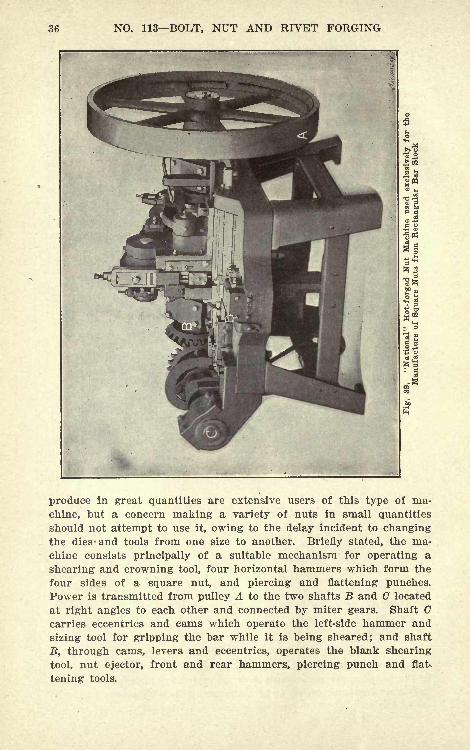
Fig. 39 shows a type of nut making machine which is only applicable
to the manufacture cf square nuts, but produces this class of nuts
free from fins and burrs at a rapid rate. Nut manufacturers who
36 NO. 113 BOLT, NUT AND RIVET FORGING
.>02
-
.s ggtf
: ccS
produce in great quantities are extensive users of this type of ma-
chine, but a concern making a variety of nuts in small quantities
should not attempt to use it, owing to the delay incident to changingthe dies -and tools from one size to another. Briefly stated, the ma-chine consists principally of a suitable mechanism for operating a
shearing and crowning tool, four horizontal hammers which form the
four sides of a square nut, and piercing and flattening punches.
Power is transmitted from pulley A to the two shafts B and G located
at right angles to each other and connected by miter gears. Shaft Ccarries eccentrics and cams which operate the left-side hammer and
sizing tool for gripping the bar while it is being sheared; and shaft
B, through cams, levers and eccentrics, operates the blank shearing
tool, nut ejector, front and rear hammers, piercing punch and flak
tening tools.
NUT FORGING MACHINES 37
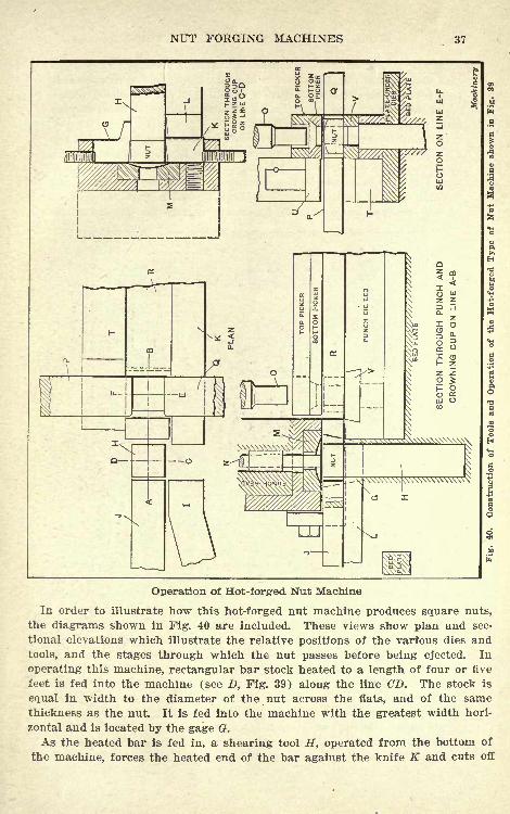
Operation of Hot-forg-ed Nut Machine
In order to illustrate how this hot-forged nut machine produces square nuts,
the diagrams shown in Fig. 40 are included. These views show plan and sec-
tional elevations which illustrate the relative positions of the varfous dies and
tools, and the stages through which the nut passes before being ejected. In
operating this machine, rectangular bar stock heated to a length of four or five
feet is fed into the machine (see D, Fig. 39) along the line CD. The stock is
equal in width to the diameter of the nut across the flats, and of the samethickness as the nut. It is fed into the machine with the greatest width hori-
zontal and is located by the gage G.
As the heated bar is fed in, a shearing tool H, operated from the bottom of
the machine, forces the heated end of the bar against the knife K and cuts off
38 NO. 113 BOLT, NUT AND RIVET FORGING
a suitable blank; as this tool continues to rise, it presses the nut blank
into the crowner cup M, which is located directly above the shearingtool. While the shearing operation is taking place, the sizing tool /,
which moves in a line parallel with the side hammer J, holds the bar
tightly against the stationary sizer K.
Gripping the bar in this manner tends to give a better shearing cut.
The shearing tool H is now lowered until its top face is in line with
the bottom of the side hammer J, and at the same time the kickout N,
operated through a hole in the crowner M, ejects the nut, preventingit from sticking in the cup. The shearing tool now remains in its
"down" position while the side hammer J carries the nut along line
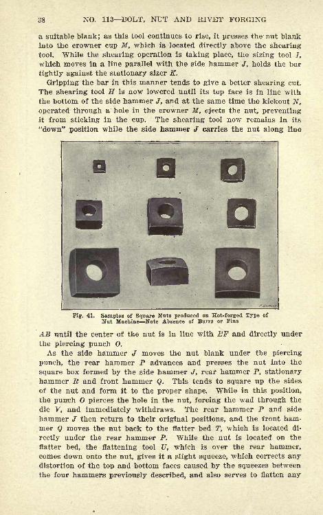
Tig. 41. Samples of Square Nuts produced on Hot-forged Type of
Nut Machine Note Absence of Burrs or Fins
AB until the center of the nut is in line with EF and directly under
the piercing punch 0.
As the side hammer J moves the nut blank under the piercing
punch, the rear hammer P advances and presses the nut into the
square box formed by the side hammer J, rear hammer P, stationary
hammer R and front hammer Q. This tends to square up the sides
of the nut and form it to the proper shape. While in this position,
the punch O pierces the hole in the nut, forcing the wad through the
die V, and immediately withdraws. The rear hammer P and side
hammer J then return to their original positions, and the front ham-mer Q moves the nut back to the flatter bed T, which is located di-
rectly under the rear hammer P. While the nut is located on the
flatter bed, the flattening tool U, which is over the rear hammer,comes down onto the nut, gives it a slight squeeze, which corrects anydistortion of the top and bottom faces caused by the squeezes between
the four hammers previously described, and also serves to flatten any
NUT FORGING MACHINES 39
fins resulting from the piercing operation. The flattening tool Uthen rises, and the flatter bed T withdraws, allowing the finished
nut to drop out of the machine. A completed nut is made at each
revolution of the flywheel, and the machine is operated at from 60 to
90 revolutions per minute, depending upon its size.
Some .idea of the character of the work turned out by the hot-
forged nut machine can be obtained from Fig. 41, which shows a
representative group of square nuts just as they come from the ma-chine. The nuts produced by these machines are entirely free fromfins or burrs, are of excellent finish, and are ready for tapping di-
rectly after being forged.
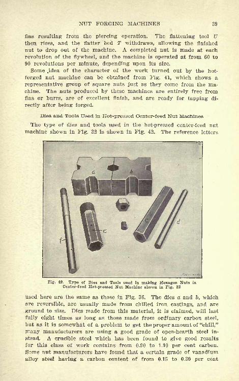
Dies and Tools Used in Hot-pressed Center-feed Nut Machines
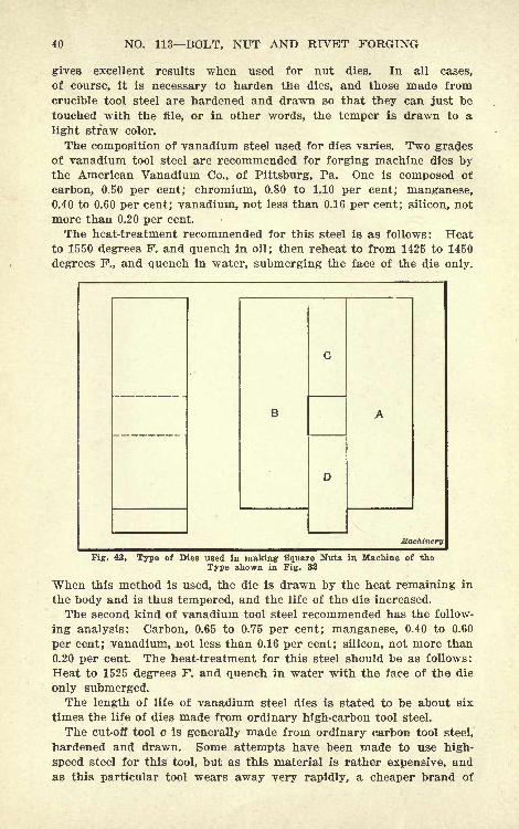
The type of dies and tools used in the hot-pressed center-feed nutmachine shown in Fig. 32 is shown in Fig. 42. The reference letters
Fig. 42. Type of Dies and Tools used in making Hexagon Nuts in
Center-feed Hot-pressed Nut MacMne shown in Fig. 32
used here are the same as those in Fig. 36. The dies a and &, whichare reversible, are usually made from chilled iron castings, and are
ground to size. Dies made from this material, it is claimed, will last
fully eight times as long as those made from ordinary carbon steel,
but as it is somewhat of a problem to get the proper amount of "chill,"
many manufacturers are using a good grade of open-hearth steel in-
stead. A crucible steel which has been found to give good results
for this class of work contains from 0.90 to 1.10 per cent carbon.
Some nut manufacturers have found that a certain grade of vanadium
alloy steel having a carbon content of from 0.15 to 0.30 per cent
40 NO. 113 BOLT, NUT AND RIVET FORGING
gives excellent results when used for nut dies. In all cases,
of course, it is necessary to harden the dies, and those made from
crucible tool steel are hardened and drawn so that they can just be
touched with the file, or in other words, the temper is drawn to a
light straw color.
The composition of vanadium steel used for dies varies. Two gradesof vanadium tool steel are recommended for forging machine dies bythe American Vanadium Co., of Pittsburg, Pa. One is composed of
carbon, 0.50 per cent; chromium, 0.80 to 1.10 per cent; manganese,0.40 to 0.60 per cent; vanadium, not less than 0.16 per cent; silicon, not
more than 0.20 per cent.
The heat-treatment recommended for this steel is as follows: Heatto 1550 degrees F. and quench in oil; then reheat to from 1425 to 1450
degrees F., and quench in water, submerging the face of the die only.
Machinery
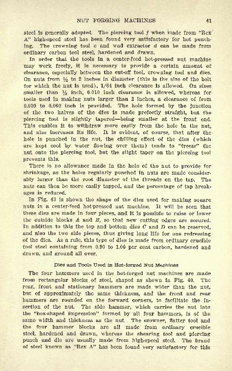
Fig. 43. Type of Dies used in making Square Nuts in Machine of the
Type shown in Fig. 32
When this method is used, the die is drawn by the heat remaining in
the body and is thus tempered, and the life of the die increased.
The second kind of vanadium tool steel recommended has the follow-
ing analysis: Carbon, 0.65 to 0.75 per cent; manganese, 0.40 to 0.60
per cent; vanadium, not less than 0.16 per cent; silicon, not more than
0.20 per cent. The heat-treatment for this steel should be as follows:
Heat to 1525 degrees F. and quench in water with the face of the die
only submerged.The length of life of vanadium steel dies is stated to be about six
times the life of dies made from ordinary high-carbon tool steel.
The cut-off tool c is generally made from ordinary carbon tool steel,
hardened and drawn. Some attempts have been made to use high-
speed steel for this tool, but as this material is rather expensive, andas this particular tool wears away very rapidly, a cheaper brand of
NUT FORGING MACHINES 41
steel is generally adopted. The piercing tool / when made from "Rex"
A" high-speed steel has been found very satisfactory for hot punch-
ing. The crowning tool e and wad extractor d can be made from
ordinary carbon tool steel, hardened and drawn.
In order that the tools in a center-feed hot-pressed nut machine
may work freely, it is necessary to provide a certain amount of
clearance, especially between the cut-off tool, crowning tool and dies.
On nuts from % to 2 inches in diameter (this is the size of the bolt
for which the nut is used), 1/64 inch clearance is allowed. On sizes
smaller than y2 inch, 0.010 inch clearance is allowed, whereas for
tools used in making nuts larger than 2 inches, a clearance of from0.020 to 0.060 inch is provided. The hole formed by the junction
of the two halves of the dies is made prefectly straight, but the
piercing tool is slightly tapered being smaller at the front end.
This enables it to withdraw more easily from the hole in the nut,
and also increases its life. It is evident, of course, that after the
hole is punched in the nut, the chilling effect of the dies (whichare kept cool by water flowing over them) tends to "freeze" the
nut onto the piercing tool, but the slight taper on the piercing tool
prevents this.
There is no allowance made in the hole of the nut to provide for
shrinkage, as the holes regularly punched in nuts are made consider-
ably larger than the root diameter of the threads on the tap. Thenuts can then be more easily tapped, and the percentage of tap break-
ages is reduced.
In Fig. 43 is shown the shape of the dies used for making squarenuts in a center-feed hot-pressed nut machine. It will be seen that
these dies are made in four pieces, and it is possible to raise or lowerthe outside blocks A and B, so that new cutting edges are secured.
In addition to this the top and bottom dies G and D can be reserved,and also the two side pieces, thus giving long life for one redressingof the dies. As a rule, this type of dies is made from ordinary crucible
tool steel containing from 0.90 to 1.00 per cent carbon, hardened anddrawn, and ground all over.
Dies and Tools Used in Hot-forgred Nut Machines
The four hammers used in the hot-forged nut machines are madefrom rectangular blocks of steel, shaped as shown in Fig. 40. Therear, front and stationary hammers are made wider than the nut,
but of approximately the same thickness, and the front and rear
hammers are rounded on the forward corners, to facilitate the in-
sertion of the nut. The side hammer, which carries the nut into
the "box-shaped impression" formed by all four hammers, is of the
same width and thickness as the nut. The crowner, flatter tool andthe four hammer blocks are all made from ordinary crucible
steel, hardened and drawn, whereas the shearing tool and piercing
punch and die are usually made from high-speed steel. The brandof steel known as "Rex A" has been found very satisfactory for this
42 NO. 113 BOLT, NUT AND RIVET FORGING
11
1
CM <M CM CM CM <N CO
iCMC>CiCiCOCOCOCO-*^f-^-*lO
xH">po r-^ -4* 0*0 HMi <M CM C^ <M CO
^1 T-l TH ^-, ^ T-KM -N Ci (M CO CO CO T}< Tf ^
C? C* CJ <NC^ OJ CO
'ci c'Tot'o? co co so eo 5?^ <*
CM Cl O <?l CO
0S
^JcS
H^[^tt^-?ia^*t>^r+o r4>-HtHe<^t)xH"~!
l CM Ci OJ Oi CJ TO CO CO Tt< -^ * 1C LO O
C<Oi<MCi<MCOCOCOCOrri
<McMC*c>'>
/?>c^roco?0'!f-^| OiOoo
^^^.^H" ^ (^ Ci o) co TO CO CO rt*'
NUT FORGING MACHINES,
purpose. The tools used in the hot-forged nut machine do not wearout nearly so quickly as those used in the hot-pressed type of ma-
chine, owing to the fact that there is not the same scraping action
against the surfaces of the tools.
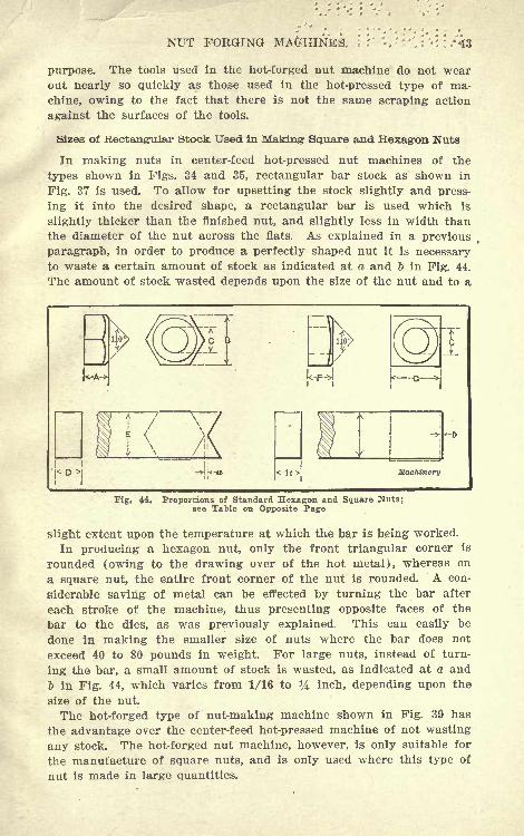
Sizes of Rectang-ular Stock Used in Making- Square and Hexagon Nuts
In making nuts in center-feed hot-pressed nut machines of the
types shown in Figs. 34 and 35, rectangular bar stock as shown in
Fig. 37 is used. To allow for upsetting the stock slightly and press-
ing it into the desired shape, a rectangular bar is used which is
slightly thicker than the finished nut, and slightly less in width than
the diameter of the nut across the flats. As explained in a previous
paragraph, in order to produce a perfectly shaped nut it is necessaryto waste a certain amount of stock as indicated at a and 6 in Fig. 44.
The amount of stock wasted depends upon the size of the nut and to a
.> k-a Machinery
Fig. 44. Proportions of Standard Hexagon and Square Nuts;see Table on Opposite Page
slight extent upon the temperature at which the bar is being worked.
In producing a hexagon nut, only the front triangular corner is
rounded (owing to the drawing over of the hot metal), whereas on
a square nut, the entire front corner of the nut is rounded. A con-
siderable saving of metal can be effected by turning the bar after
each stroke of the machine, thus presenting opposite faces of the
bar to the dies, as was previously explained. This can easily be
done in making the smaller size of nuts where the bar does not
exceed 40 to 80 pounds in weight. For large nuts, instead of turn-
ing the bar, a small amount of stock is wasted, as indicated at a and
& in Fig. 44, which varies from 1/16 to ^4 inch, depending upon the
size of the nut.
The hot-forged type of nut-making machine shown in Fig. 39 has
the advantage over the center-feed hot-pressed machine of not wasting
any stock. The hot-forged nut machine, however, is only suitable for
the manufacture of square nuts, and is only used where this type of
nut is made in large quantities.


UNIVERSITY OF CALIFORNIA LIBRARYBERKELEY
Return to desk from which borrowed.
This book is DUE on the last date stamped below.
TiBRARYUSEONL
HAR29W3
LIBRARY USE OffLY
MAH 3 1
CIRCULATIONDlPT.
1998
1993
LD 21-100m-ll,'49(B7146sl6)476
YC 53944
01*5500633
7JT x
1 113 "I'-t 1
UNIVERSITY OF CALIFORNIA LIBRARY
MACHINERY'SHANDBOOK
For MACHINE SHOPAND DRAFTING-ROOM
A REFERENCE BOOK ON MACHINEDESIGN AND SHOP PRACTICE FORTHE MECHANICAL ENGINEER,DRAFTSMAN, TOOLMAKER ANDMACHINIST.
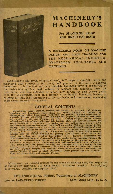
MACHINERY'S Handbook comprises nearly 1400 pages of carefully edited and
condensed data relating to the theory and practice of the machine-building
industries. It is the first and only complete handbook devoted exclusively to
the metal-working field, and contains in compact and condensed form the
information and data collected by MACHINERY during the past twenty years.
It is the one essential book in a library of mechanical literature, because it
contains all that is of importance in the text-books and treatises on mechanical
engineering practice. Price $5.00.
GENERAL CONTENTSMathematical tables Principal methods and formulas in arithmetic and algebra
Logarithms and logarithmic tables Areas and volumes Solution of triangles and
trigonometrical tables Geometrical propositions and problems Mechanics Strength of
materials Riveting and riveted joints Strength and properties of steel wire Strength
and properties of wire rope 'Formulas and tables for spring design Torsional strength
Shafting Friction Plain, roller and ball bearings Keys and keyways Clutches and
couplings Friction brakes Cams, cam design and cam milling Spur gearing Bevel
gearing Spiral gearing Herringbone gearing Worm gearing Epicyclic gearing Belting
and rope drives Transmission chain and chain drives Crane chain Dimensions of small
machine details Speeds and feeds of machine tools Shrinkage and force fit allowances
Measuring tools and gaging methods Change gears for spiral milling Milling machine
indexing Jigs and fixtures Grinding and grinding wheels Screw thread systems and
thread gages Taps and threading dies Milling cutters Reamers, counterbores and
twist drills Heat-treatment of steel Hardening, casehardening, annealing Testing the
hardness of metals Foundry and pattern shop information The welding of metals
Autogenous welding Thermit welding Machine welding Blacksmith shop information
Die casting Extrusion process Soldering and brazing Etching and etching fluids
Coloring metals Machinery foundations Application of motors to machine tools Dynamoand motor troubles Weights and measures Metric system Conversion tables Specific
gravity Weights of materials Heat Pneumatics Water pressure and flow of water
Pipes and piping Lutes and cements Patents.
MACHINERY, the leading journal in the machine-building field, the originator
of the 25-cent Reference and Data Books. Published monthly. Subscription,
$2.00 yearly. Foreign subscription, $3.00.
THE INDUSTRIAL PRESS, Publishers of MACHINERY
140-148 LAFAYETTE STREET NEW YORK CITY, U. S. A.
Related Documents


