LOW VOLTAGE SWITCHGEAR DEPARTMENT PHILADELPHIA, PA. UBxAfcY COPY GEH - 2022 DO NOT REMOTE SUPERSEDES GEI - 14491 F 37 NORTHEAST ELECTRICAL HIGH - SPEED DIFFERENTIAL RELAYS r t I. IMRM - A sf , Types CFD 12 A and CFD 12 B A GENERAL 01 ELECTRIC

Welcome message from author
This document is posted to help you gain knowledge. Please leave a comment to let me know what you think about it! Share it to your friends and learn new things together.
Transcript
L O W V O L T A G E S W I T C H G E A R D E P A R T M E N T
P H I L A D E L P H I A , P A .
UBxAfcY COPY GEH-2022DO NOT REMOTE S U P E R S E D E S G E I - 1 4 4 9 1F
37NORTHEAST ELECTRICAL
HIGH-SPEEDDIFFERENTIAL RELAYS
r
t
I.I M R M -A
s f ,
Types
CFD12 A and CFD12B
A
G E N E R A L 01E L E C T R I C
Courtesy of NationalSwitchgear.com
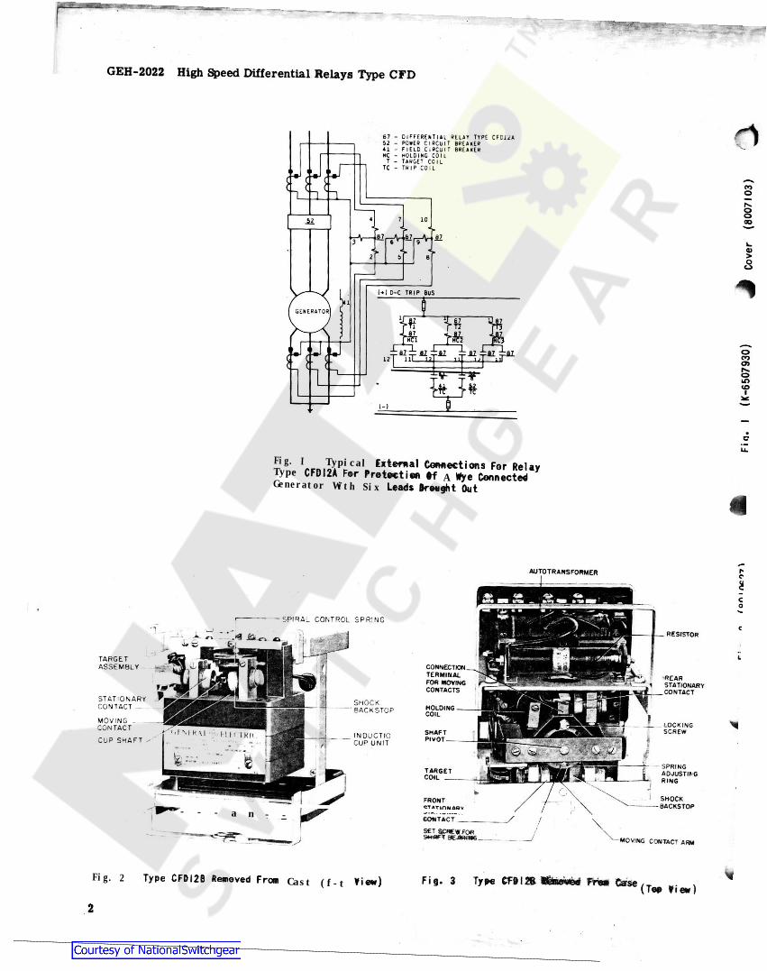
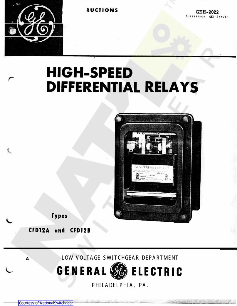
Fig. I Typical Type A Generator With Six
- - - a n - -
Fig. 2 Cast (f-t
V-' '
W?~7-
GEH-2022 High Speed Differential Relays Type CFD
f a 7 - D I F F E R E N T I A L R E L A Y T Y P E C F0l* A$2 - P O R E R C I R C U I T B R E A K E R4 1 - F| £ I D C I R C U I T B R E A K E RH C - H O L D I N G C O I L
T - T A R G E T C O I LT C - T R I P C O I LI i
COo
§10Jil CO
T40)>eS
!> ( ) D-C TRIP BUS
G E N E R A T O R
OCOo>roIT)
to
( -)
ou.
CFO,2» F.,»5512V^WSrLeads draught Out
AUTOTRANSFORMER hcaca
— SPIRAL CONTROL SPRINGc_ RESISTORi
LTARGETASSEMBLY CONNECTION
TERMINALFOR MOVINGCONTACTS
REARSTATIONARY_ CONTACT
STATIONARYCONTACT _ SHOCK
‘ BACKSTOP HOLDINGCOIL
MOVINGCONTACT
CUP SHAFT x
LOCKINGSCREWI M «'1 HH IKI i SHAFT
PIVOTINDUCTIOCUP UNIT
6 SPRINGADJUSTINGRING
TARGETCOIL
SHOCKBACKSTOP
FRONTCTATiniUARY
CONTACT
s irfBfcSSiSs MOVING CONTACT ARM
*Type CFDI2B Removed From Type CF9 I 2B Kfamed From CaseFig. 3Y iew ) ( Tap View )
2
Courtesy of NationalSwitchgear.com
APPLICATIONHigh Speed differential relaying such as that
afforded by the Type CFD is recommended forprotection of generators of 2000 capacity andabove, and for motors and synchronous condensersof 3000 H.P. (or and above. Other forms ofdifferential protection are recommended for thelower ratings of generators, motors, and synchronouscondensers. It is desirable that if one machine isdifferentially protected, all machinesparalleledwithit on the same bus also have similar protection.
The Type CFD relays comprise a group that isused for differential protection of alternating cur-rent machines against both phase-to-phase andphase-to-ground faults. The relays function on thedifference between the current entering one end of awinding that leaving the other end. When thedifference exceeds a certain minimum value due toan internal fault the relay will close its contacts.An external fault will not produce a difference incurrent, and therefore will not cause relay opera-tion. Likewise, the relay will not respond to opencircuits or turn-to-turn short circuits, neither ofwhich affect the difference between current enteringand current leaving the winding. Refer to Fig. 1.
Phase-to-ground protection requires that theneutral of the machine (or another machine operatingin parallel) be grounded. A small portion of thewinding next to the neutral will not be protected, theamount being determined by the voltage necessaryto cause minimum pickup current to flow throughthe neutral to ground impedance. Current limitingdevices in the neutral ground circuit increase thisimpedance, and will decrease the coverage of therelay.
Delta connected machines with both ends ofeach winding available can readily connectedfor phase-to-phase fault protection. The currenttransformers in the windings should have the sameratio as the transformers in the lines. Whereonly four leads! including a neutral,, are brought
from a differential for ground only can be obtained. If only three leads
are brought out, differential protection cannot beobtained. In this case an overcurrent relay maybe used to detect ground faults provided there isa grounded neutral in the bus circuit to whichthe machine is connected.
When a generator and power transformer areoperated as a unit, separate relaying is recom-mended for each. The sensitive protection of aCFD relay can be given a generator whereas itwould be inadvisable for a power transformer. It ispermissible to use one set of current transformersin common between the two differential such a way that the transformer protective relayacts as backup protection for the generator.
When current-differential protection is pro-vided for a-c machines, the field switch should be
at same time that the is from the system. Elec-
trically operated field circuit breakers, or are generally used for this application, but
in some cases field switches.consisting of an air breaker with a trip and a field discharge clip,. are employed.
Where the total RMS symmetrical current thatwould flow in a differential relay coil of negligibleimpedance high voltage may resultwith relays, and a + limiter may be required across each phase of thecurrent transformer secondaries. Where taps onthe current transformer secondary windings areunused or do not exist, currents below amperesare safe without limiters. Where taps are used onthe CT secondaries, limiters are not necessary-if
the current is less than 84 X(Active Turns)’
(Total Turns) Installations not shown to be safe by the approximaterule given above should referred to the GeneralElectric Company with data on the fault currents,CT ratios, and CT excitation characteristics todetermine whether limiters are actually needed.
If tbe neutral of a machine is grounded, it isadvisable to provide a neutral breaker which can betripped to open the ground-return circuit of thefault current as quickly as possible. It is usuallypreferable to trip the neutral breaker, mainbreaker,and field breaker simultaneously, by means of ahand-reset auxiliary relay.
A alarm should provided in eachstation. This is usually connected through anauxiliary switch on each of the neutral breakers, sothat the alarm will sound in case all neutralbreakers are open.
Reg. Trade-Mark of General Electric Company
instructions do not purport to in contingency to be met in connection with operation or information be
which are not covered for the the matter be referred to the General Electric Company.
l Denotes change since superseded issue. 3
HIGH-SPEED DIFFERENTIAL RELAYSTYPE CFD
rINTRODUCTION
kva
kva) relays and in
rtripped automatically . themachine disconnected
con-tactors,
manually operatedcircuit shunt
and*
is excessive,sensitive differential Thyrite
84
2
be
be
w out machine, relayingfaults
ground be
only
-H
These cover ail details or variations equipment nor to provide for every possiblemaintenance. Should further
sufficiently purchaser’s purposes,installation, desiredc or should particular problems arise should
Courtesy of NationalSwitchgear.com
GEH-2022 High Speed Relays Type CPD
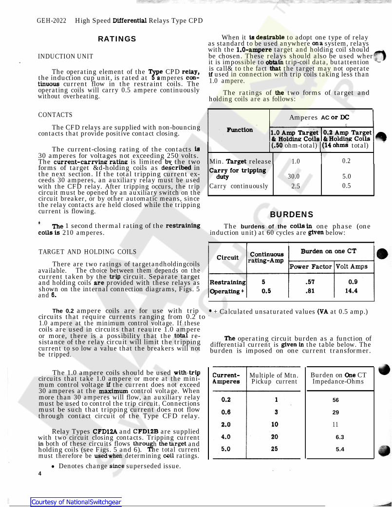
RATINGS When it to adopt one type of relayas standard to be used anywhere system, relayswith the target and holding coil should
INDUCTION UNIT be chosen. These relays should also be used whereit is impossible to trip-coil data, butattention
The operating element of the CPD is call& to the fact the target may not operatethe induction cup unit, is rated at amperes used in connection with trip coils taking less than
current flow in the restraint coils. The 1.0 ampere.operating coils will carry 0.5 ampere continuouslywithout overheating. The ratings of two forms of target and
holding coils are as follows:
CONTACTS Amperes AC The CFD relays are supplied with non-bouncing
contacts that provide positive contact closing.
The current-closing rating of the contacts 30 amperes for voltages not exceeding 250 volts.
ohm-total) total)
The is limited the two Min. release 1.0 0.2forms of target &d-holding coils as inthe next section. If the total tripping current ex-
ceeds 30 amperes, an auxiliary relay must be used 30.0 5.0with the CFD relay. After tripping occurs, the trip Carry continuously 2.5 0.5circuit must be opened by an auxiliary switch on thecircuit breaker, or by other automatic means, sincethe relay contacts are held closed while the trippingcurrent is flowing. BURDENS* 1 second thermal rating of the
210 amperes.The burdens of the one phase (one
induction unit) at 60 cycles are below:I I I
TARGET AND HOLDING COILS
There are two ratings of targetandholdingcoilsavailable. The choice between them depends on thecurrent taken by the circuit. Separate targetand holding coils provided with these relays asshown on the internal connection diagrams, Figs. 5and
The 0.2 ampere coils are for use with trip + Calculated unsaturated values at 0.5 amp.)circuits that require currents ranging from 0.2 to 1.0 ampere at the minimum control voltage. If thesecoils are used in circuits that reauire 1.0 ampereor more, there is a possibility that the re-sistance of the relay circuit will limit the tripping operating circuit burden as a function ofcurrent to so low a value that the breakers will not differential current is the table below. Thebe tripped. burden is imposed on one current transformer.
The 1.0 ampere coils should be used circuits that take 1.0 ampere or more at the mini-mum control voltage the current does not exceed30 amperes at the control voltage. Whenmore than 30 amperes will flow, an auxiliary relaymust be used to control the trip circuit. Connectionsmust be such that tripping current does not flowthrough contact circuit of the Type CFD relay.
Relay Types and are suppliedwith two circuit closing contacts. Tripping current
both of these circuits flows h andholding coils (see Figs. 5 and 6). he total currentmust therefore be determining ratings.
l Denotes change superseded issue.4
Multiple of Mtn.Pickup current
Burden on CTImpedance-Ohms
56
29
11
6.3
5.4
Differential
is desirableon a
1.0-ampere
obtainthatrelay, ^con-
tinuousthe
or DC
Function 1.0 Amp Target 0.2 Amp Target& Holding Coils & Holding Coils
I (14 ohms(.50is
Targetcurrent-carrvine ratine bv.described Carry for tripping
duty
restraining coils inThecoils is given
Burden on one CTContinuousrating-AmpCircuit
Volt AmpsPower Factortrip
0.95 .57RestrainingOperating *
are14.40.5 .816.
(VA*
total Thegiven in
with trip Current-Amperes
Oneif
maximum0.2 1
0.6 3
102.0CFD12A CFD12B
4.0 20in throu the target
T1 255.0coilused when
since
Courtesy of NationalSwitchgear.com

High Speed Differential Relays Type CFD GEH-2022
These relays, when not included as a part of acontrol panel, will be shipped in cartons designed toprotect them against damage. Immediately uponreceipt of the relay, an examination should be made
any damage sustained during shipment. If Or damage resulting from rough handling is
a should be filed at once with the company and the nearest Sales Office
of the General Electric Company notified promptly.
Reasonable care should be exercised in
relay in order that none of the parts are or the adjustments disturbed.
If the relays are not to be installed immediately should be stored in their original cartons
is from moisture, dust, and metallic. matter collected on the outside of
the case find its way inside when the cover isremoved and cause trouble in the operation of therelay.
RELAY TYPES* The Type relay is a three unit relayfor providing differential protection for a three phasegenerator. Each unit is provided with a double
arrangement which allows tripping of two breakers without paralleling the trip circuits
If only one breaker is to be controlled, the contact;should be connected in parallel.
The Type is similar to the that it has only one unit and is applicable to
only one phase. It can be used for single-phasegenerator protection provided that one line isgrounded, or for a three-phase generatorapplicationwhere flexible panel mounting is required.
INTERNAL CONSTRUCTIONThe CFD relays are of the induction cylinder
construction. The unit consists of a multi-pole a stationary central core, and a cup-like
rotor. The cup rotates about a verticalaxis in air gap the and core Thelight weight cylinder offers a high’ ratioof torque to inertia and results in a fast operatetime.
CUP AND
This, contact with a rear extension of the contact arm. A shock backstop absorbs
shock and reduces the tendency of the moving con-tact to close if the mounting panel is jarred. Fig. 4shows arrangement of the contact mechanism
contact (G) is mounted on a (F) which is spaced from a thin
diaphragm (C) by a washer (D). The cap holdsthese, in Place on a slightly inclined tube
a close fitting stainless steel ball of the moving contact is and steel ball with the result that there is
little no rebound or vibration of the closing con-tacts.
The moving contacts are supported on a molded arm which is attached to the rotor shaft
through a clutch arrangement. The clutch acts as ashock when the contacts close under fault
and reduces their tendency to reboundIt consists Of a felt lined cylinder between the and moving contact arm. The amount of frictional
to slippage is controlled by Pressure the felt surface and the shaft bymeans of a screw on the side of the contact arm.
The axis of the cylinder is supported at the end by a steel pivot which rotates against a
selected sapphire jewel. The jewel is spring mountedto Protect it from shocks. The upper end of theshaft is held in place by a polished steel pivot which
down through a bronze guide bearingmounted the end of the shaft.
The of the induction unit is of the eightPole construction, buttwo sets of three.
uses only six of the poles inOne set carries the currents
transformers in one phase on each of the generator winding (see Fig. 1). The
other set carries the difference current between two current transformers.
CONTACT STRUCTURE
Fig. Contact Assembly CFD Relays
The contacts are silver-to-silver elements andare a non-bounce feature to a circuit closure.
obtained byTwo circuit closing
mounting a second stationaryContact at the back of the induction unit (see Fig. 3).
* Denotes change since superseded issue.
The contact arm is held from rotating freelyby, control spring. This spring determines
differential current which will operate relay. It serves to keep the contact circuit openwhen the relay is de-energized.
5
RECEIVING, HANDLING AND STORAGE
packing theinjured
y
in atheyplace that freechips Foreign
may
forinjuryevident, claimtransportation
un-DESCRIPTION
makesmoving
CFD12A
the AAA "flatcontactcircuit
The stationaryspiral spring (E)
(A) whichl (B), the
transferred to theCFD12A contains
energyspring
CFD12Bexcept
or
plastic
absorberconditions shaftstator,
induction statorbetweenaluminium
the adjusting theresistancecr><£? betweeno
oI
STATOR6 0
\ £lowercn
u.,\Ny X'xX- FI
projects G(iin
* stator
I * ill 1 < ill 11 il11111 > illfrom the currentside the
4 StationaryType
For
theinsure aconstructed withpositive
action Is
theminimum
Courtesy of NationalSwitchgear.com

GER-2022 High Speed Differential Relays Type CFD
TARGET HOLDING COIL
The target mechanism (Fig. 2) drops an orangeThe holding coil is used to hold the contacts in
position while current is flowing throughcolored surface when the relay trips a breaker.This indicator is unlatched by a solenoid through
It acts on an armature which is carried byThe coil is connected
which the tripping current flows. It is reset manuallythe contact arm.
by a reset lever which extends through the lowerseries with the trip circuit, and therefore must be
edge of the relay cover.de-energized by opening the trip circuit at a external to the relay.
LOCATIONThe location should be clean and dry, free from
dust and excessive vibration, and well lighted tofacilitate inspection and testing.
MOUNTINGThe relay should be mounted on a vertical sur-
face. The outline either or semiflush panel mounting is shown in Fithe three unit case, and in Fig. 1single unit case
around the adjusting prevents unintentionalmotion of the ring. The hexagonal locking screwshould again be tightened after the adjustment hasbeen made. It is not recommended that the pickupbe set less than 0.1 ampere (this may be as high as0.16 ampere for the rear contact to close) in anycase. If the relay is mounted on a swinging panel,the pickup should not be reduced at all.
CONTACTS
CONNECTIONSThe internal connection diagrams are shown in
Figs. 5 and 6 for the Types and respectively. Studs 13, 15 and 17 on the double endcases are used for test purposes only. A typicalexternal wiring diagram is shown in Fig. 1.
The contact circuits should be whenonly one trip circuit is controlled. This can be honeby terminals 11 and on the orterminals 2 and 3 on the
The contact gap may be adjusted by looseningthe locking screws which clamp the contact andbackstop barrels place. The screw should beloose enough only to allow the barrels to rotate intheir sleeves. The shock backstop should bepositioned so that it holds the moving contact armpointing directly forward The stationary contactbarrel should be rotated until it just closes the
*contact circuit and then backed away 3.2 revolutions.This will provide a gap of approximately inch.Adjust the rear stationary contact barrel so that thecircuit is at the same time the front con-tacts close. -Tighten the screws which secure theshock stop and contact barrels.
One of the mounting studs or screws should bepermanently grounded by a conductor not less thanNo. 12 B&S gage copper wire or its equivalent.
CURRENT TRANSFORMERS
Relays are shipped from factory with contactsset for gap. relays are not mounted onswing doors and are free from shock, the contact gapcan be reduced to 0.050 inches and the time will beas shown by the lower curve in Fig. 6.
Proper differential protection requires that thecurrent transformers to which Type CFD relaysareconnected be accurate to within 1 or cent up totwice normal current. Above twice normal currentaccuracy is not so important because of the CFDcharacteristics. (See Principles of
ADJUSTMENTS
Should it be necessary to change the stationarycontact mounting spring, remove the contact barreland sleeve as a complete unit, end unscrew the cap.The contact and spring may then be removed.
The moving contact may be removed by loosen-ing the screw which secures it to the contact arm,and sliding it from under the screw head.
l MINIMUM PICKUP CLUTCH
These relays are adjusted at their left front contacts with 0.2 ampere or more inone current circuit and no current in the other. Toclose the right rear contact a current as high as0.25 ampere may be required. Jf greater sensitivityis desired, it can be obtained by reducingthe tensionof the spiral control spring. Todothis, it is neces-sary to loosen the locking screw whichholds the back of the ring. The adjustingring can be rotated to change the restraint offeredby the control spring. Friction from a spring wire
for any reason the moving contact arm has removed or loosened from the rotor abaft, it
will be necessary to readjust the clutch pressure.The adjustment is made with the test connectionsshown in Fig. 9 with the current I, equal to zero(switch open). With 20 amperes flowing in therestraint circuit. the screw on the side of the contact arm be loosened from a “no position until the rotor shaft does slip. The clutch
remain tight as current isreduced, slipping stops at a
* Denotes change since superseded issue.
the closedthem. ft. «
moving in
point
INSTALLATIONring
surface. 10 forfor the
and paneldrillingfor
(CFD12A),(CFD12B). 3
in
CFD12A CFD12B
.100oaralleled comDleted
jumpering 1‘2 CFD12ACFD12B.
.100 inch If
2 per
Operation).
the factory toclose Ifbeen
movinvc;lipfTshouldhexagonal
adjusting
^Jshould enough that theminimum of 10amperes.
6
Courtesy of NationalSwitchgear.com
High Speed Type CFD GEH-2022
No further adjustments should be necessary. Theabove need be followed only in specialcases of recalibration or contact replacement. Anytrouble should be corrected as described underMAINTENANCE.
INSPECTIONThe relay should be inspected at the time of
installation for tarnished contacts and loose screwsthat have resulted from storage and handling.
r
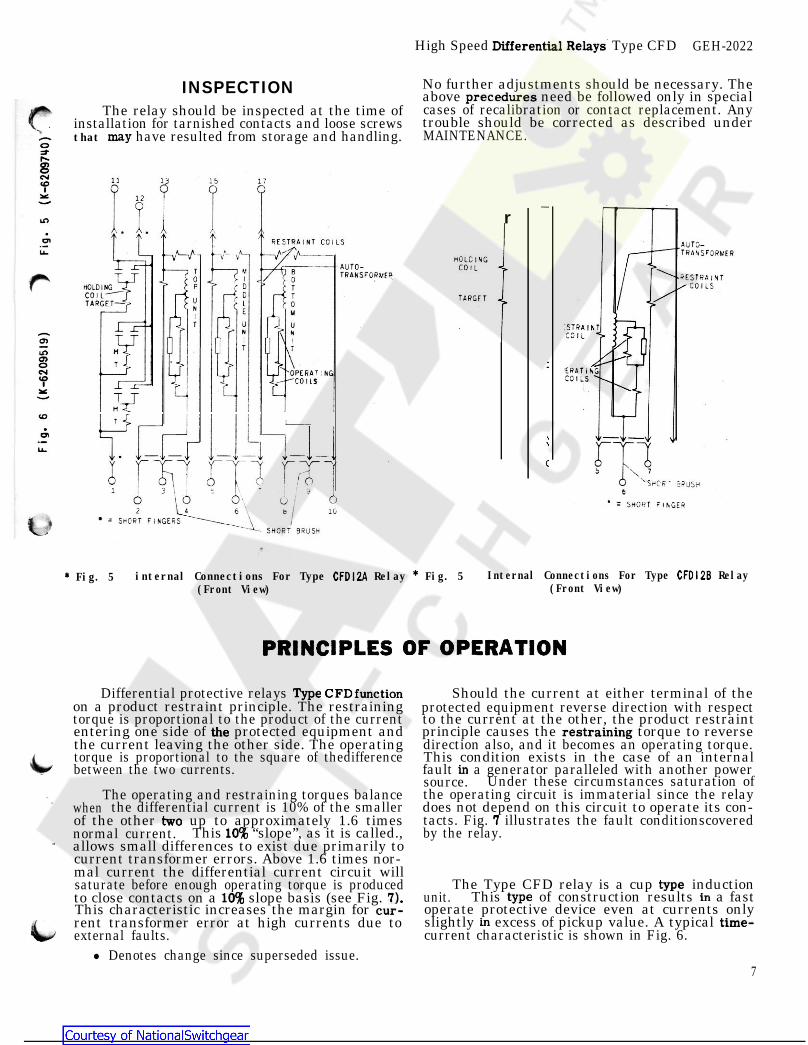
Fig. 5 internal Connections For Type Relay Fig. 5(Front View)
Internal Connections For Type Relay(Front View)
Differential protective relays on a product restraint principle. The restrainingtorque is proportional to the product of the currententering one side of protected equipment andthe current leaving the other side. The operatingtorque is proportional to the square of thedifferencebetween the two currents.
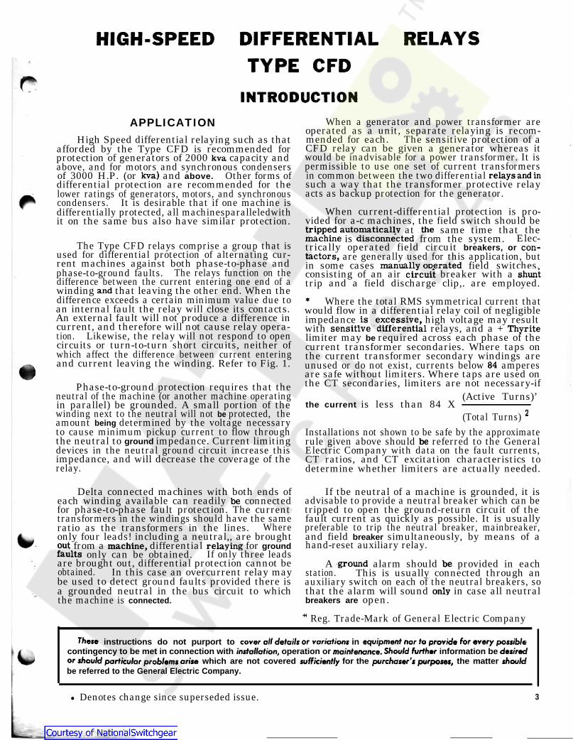
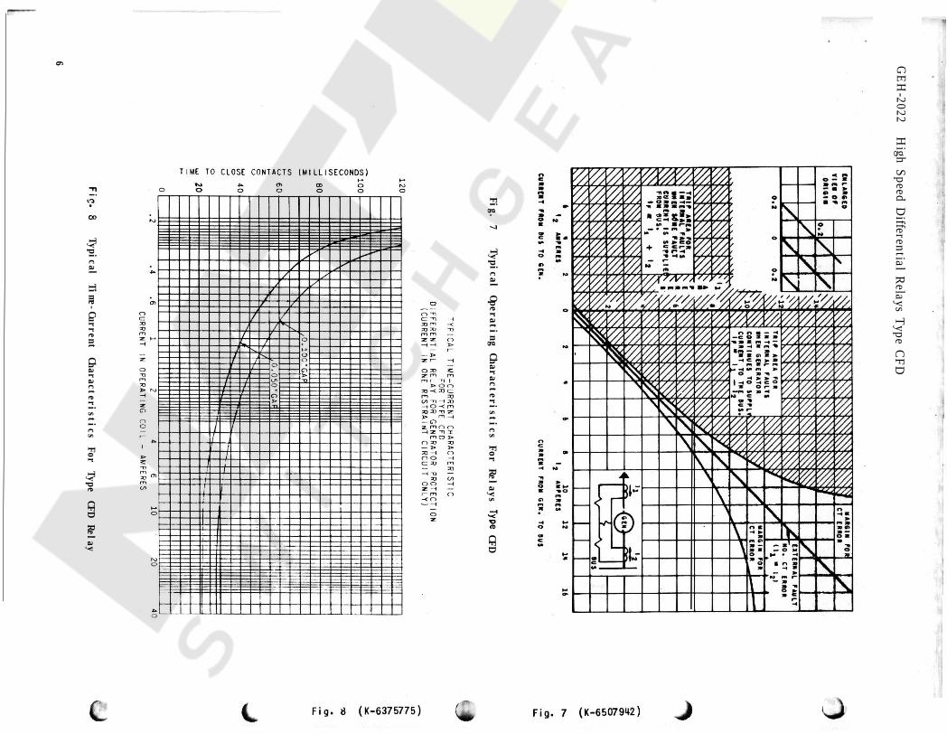
The operating and restraining torques balancewhen the differential current is 10% of the smallerof the other up to approximately 1.6 timesnormal current. This “slope”, as it is called.,allows small differences to exist due primarily tocurrent transformer errors. Above 1.6 times nor-mal current the differential current circuit willsaturate before enough operating torque is producedto close contacts on a slope basis (see Fig. This characteristic increases the margin for rent transformer error at high currents due toexternal faults.
l Denotes change since superseded issue.
Should the current at either terminal of theprotected equipment reverse direction with respectto the current at the other, the product restraintprinciple causes the torque to reversedirection also, and it becomes an operating torque.This condition exists in the case of an internalfault a generator paralleled with another powersource. Under these circumstances saturation ofthe operating circuit is immaterial since the relaydoes not depend on this circuit to operate its con-tacts. Fig. illustrates the fault conditionscoveredby the relay.
unit.The Type CFD relay is a cup induction
This of construction results a fastoperate protective device even at currents onlyslightly excess of pickup value. A typical current characteristic is shown in Fig. 6.
7
Differential Relays
precedures
may
11 8 l b 17O QQ
12
i
L i/ \ / ^. A / i
A i \RESTRAINT COILS AUTO-TRASSFORWER-v-/ -"V V HOLDING
COIL— AUTO-T TRANSFORVER RESTRAINT/ C O I L S
0' DPHOLDING
COILTARGET Y
D TARGETrU LeN E
R nT u : STRAINT ;COIL > <N N\0 I
T
1 1 ERATING'OPERATINGC O I I S COILS
LI
\
cSHCR ' -RUSH
O " = SHORT FINGERe \-A" = SHCRT FINGERS
SHORT BRUSH
CF0I 2B*CFDI 2A*
PRINCIPLES OF OPERATION
Type CFDfunction
restrainingthe
in
7two10%
typetype in10% 7).
cur -time-in
Courtesy of NationalSwitchgear.com
GEH-2022
High Speed D
ifferential Relays Type CFD
Fig. 7Typical Operating Characteristics For Relays
CFD
Typical Time-Current Characteristics For Type CFD Relay
6
TIME TO CLOSE CONTACTS ( MILLISECONDS ) ci < n© — *» * » *"
CMK> CT> CD O NJ '~n o o o o o oo -r\1%»<z- 0 » mH-ii a arr
m S > so- O D
onOto
\z C3M-al /00 oro M \1111m m
ov»— • — m /* v»2 S « MO Nw »co
C er»"H /+r*iMO -» Ha*HI \Cl /M
HI
Z'tV,m o/z M \rzj _
/f Mz/
M/ z 7777,7/ 7,£ •7<7» OZ
7jy oo o -n
c; -n;nm70 X Jm mZ Z
z£c: -<7£x> z z z z1111111!
n3i>
o o—c on JO * HI . .
JO -« » HI *"HI •ni>"H e HI
^'*s!
m z f s.O o7 >> M z:s* E I Io — >z r-z o »• »
r- HI.
O : lio o O TO *zz m mm r TI i
x* Oo70 -< 70 CZ
r » n-J > »• 3H O -« = 0* O r a—HI > H
M C
T5 O >m LP ~D Mlo70> (\J S
yo 33mC/> “n —• aD z z c ~a
v* r~zCD J3 XT1 7 /m -Hr* z ZNo — CD
z moo—« z T| xmo x>
O
X > z\I*. oO Z>— > cI I*o N s:o —i M i l lz30> ooc: 3 smIn X) Mlm
^ \—H -D -a3 COf Mm ooZ - -Ir— m-<o.— —( $O rzii--co
\oCl;rj oo o
V 2 S\ s:
o
z t J 1^*-» HI O3 0 O
— OH
^.o.CD o M
O mo
-LIilrC•o
Mr-o r +
oo
\M HI r— JOJO -o> C
4»o
F i g. 8 ( K —6375775 ) F i g. 7 ( K-6507942 )
Courtesy of NationalSwitchgear.com

High Speed Relays GEH-2022
The relays are adjusted at the factory and it is The polishing action is so delicate that no scratchesadvisable not to disturb the adjustments. If for any are left, yet corroded material will be removedreason, they have been disturbed, the following rapidly and thoroughly. The flexibility of the toolpoints should be observed restoring insures the cleaning of the actual points of contact.
SHAFT AND BEARINGSThe lower jewel screw may be removed and
the jewel tested for cracks by exploring its sur-face with the of a fine needle. The bearingshould then be screwed all the way in until itshead engages the end of the threaded core support.The upper bearing should be adjusted to allow
inch end play to the shaft.
Fine silver contacts should not be cleanedwith knives, files, or abrasive paper or cloth.Knives or files leave scratches which increase
and deterioration of contacts. Abrasivepaper or cloth may leave minute particles of in-sulating abrasive material in the contacts and thusprevent closing.
To. check the clearance between iron coreand the inside of the rotor cup, press down on thecontact arm near shaft, and thereby
mounted jewel until the cup the
inch:The shaft and cup should move about
The burnishing tool described is included the standard relay tool kit obtainable from thefactory.
PERIODIC
AND If it is to remove the rotor from
the procedure should be
The leads should first disconnected andtagged for identification in reconnecting. Theunit can then be removed with its mounting plateattached.
An operation test and inspection of the relayat intervals of months recommended. test connections are shown in Fig. 9. The re-straint circuit currents and correspond tothe same currents shown on the operating char-acteristic Fig. 7. represents the differ-ential current. The ion of current throughthe restraint circuit should be reversed? and asecond check of the made.The target operation should be checked by passing85% of rated current through the contact circuits.
saturating transformer should neat beremoved from the back of the mounting plate andthe upper of the three flat head screws holding theunit to the mounting plate then be removed.Then the entire top structure can be taken off afterremoval of the four corner screws holding the unittogether. This will give access to the cup and assembly.
To remove the shaft and rotor from the tact head assembly the spring clip at the top of theshaft must be pulled out and the clutch adjustingscrew and spring taken out of the molded contactarm.
The rotor should be handled carefully whileit is out of the unit and the should be pro-tected to keep it free of dust or metallic particles.
In reassembly, the rotor will go into the airgap easily if the parts are held the proper alignment.
CONTACT CLEANING cleaning fine silver contacts, a flexible ‘RESTRAINT
burnishing tool should be used. This consists of INTERNAL a flexible strip of metal with an etched roughened surface, resembling effect a superfine file. Fig. 9 Test Connections for Type
Differential Type CFD
MAINTENANCE
in them:
maythearcing
point
1/64 in
theCOs?r * the depressstrikes
1/16TESTINGO
the springiron. Th
toI
Thesix iso>STATORCUP II 12
U.given in
direc?necessary'following fol-the unit
lowed:operational characteristic
be
230 VOLTSOURCE,RATEDFREQUENCY
The
ADJUSTABLERESISTORS
can
stator
<$)ioh AMMETERS
IDTARGETcon-OPERATING
COILSHOLD INGCOIL
1R1Estator s
1A rr\
N-/ •/AUTO-TRANSFORMER :NOT PRESENT
IN CFD11Ain
^ 6 7*>\C O I L SO INDICATES RELAY
TERMINAL ( SEEForC O N N .
D I A G R A M . \
CFD Relaysin
9
Courtesy of NationalSwitchgear.com

GRH-2022 High Speed Relays Type CFD
PANEL LOCATION
1 3 5 7 90 0 0 0 0
0 0 0 0 0-2 4 6 8
NUMBERING OF STUDS
SURFACEMTG.
PANEL DRILLING FOR SEMI-FLUSHMOUNTING (FRONT VIEW)
PANEL DRILLING FOR MOUNTING VIEW)
VIEW SHOWNG ASSEMBLY OFHARDWARE FOR SURFACE MTG.
ON STEEL PANELS
3
F i g . O u t l i n e a n d P a n e l D r i l l i n g f o r R e l a y
10
Differential
SEMI-FLUSHMTG. SURFACE
5 3i1® 6I6 ,
56 8 SCREWir\- zt n
JK^OR STUD)c t>in|<£
“ *T12 14 16 18 20E*~IOICM
cvjlro
310lO
rO<0
ijg-18 STUDS
(OFOR04o>o04<0
<0mV. 901 3 oo
ir|<e 5* Ol
±!G u.V. 10- 3 *510‘32* -§MTG.“ SCREWrr-(FRONT VEW) -1|DRILL
*20HOLESOUTLINE115 8~V*162 32T^23232 CUTOUTS MAY
REPLACE DRILLEDHOLES
tnJDRILL6 HOLES ll I*-/fl 4-e-CASEO \
-ICM /,5CT> JO00< RANELSIS5 0>0>omica
CsJ|m mfa-5 ID- 18 STUD Q
infoo
SENS m)rr0>
OJ(ftX ID r- oo< 3 i a>2.SK o e
o-ELO^Ll
SURFACE(FRONT
Type CFDI 2A10
Courtesy of NationalSwitchgear.com
High Speed Differential Relays Type CFD
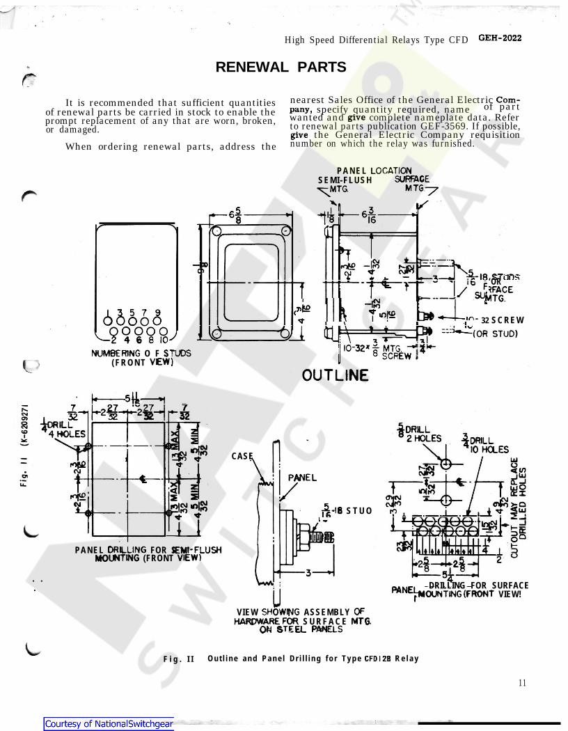
RENEWAL PARTS
It is recommended that sufficient quantities nearest Sales Office of the General Electric of renewal parts be carried in stock to enable the specify quantity required, name of partprompt replacement of any that are worn, broken, wanted and complete nameplate data. Referor damaged. to renewal parts publication GEF-3569. If possible,
the General Electric Company requisitionWhen ordering renewal parts, address the number on which the relay was furnished.
O F( F R O N T
P A N E L SEMI-FLUSH
‘OR
32 S C R E W
CASE
S T U O
PANEL FOR S (FRONT
. .. DRILLING FOR SURFACE
VIEW!
VIEW ASSEMBLY S U R F A C E
F i g . I I O u t l i n e a n d P a n e l D r i l l i n g f o r T y p e R e l a y
11
/*
GEH-2022
rCom-
pany,give
give
LOCATIONSURFACE
MTG—7T^MTG.x s
65.68n o (DawC) ¥ 18 srnns
. EFFACEi-86 6S6 3( Q O O O O )-2 4 6 8 lO"'
NUMBERING STUDSVEW )
io|?gI
*—4-I
! ir\
lw3» = •-o/ (OR STUD)
SOREST10-32* MTG.8
L OUTLINE4
^ 7~ 27__7 _2^7^ 32 3232CNrf
05 I J8 -jORILL10 *4 HOLES J ILL\pi-3C 14-- 10 HOLES=8 v LUfOf£ O<(/)
UJPANELOlu. ftil i 3
* * T *11 I nSBDRILLINGMOUNTING
;EMI-FLUSHVIEW) kil t i
Lr 3
^^MOUNTING(FRONTIIOFSHOWING
HARDWARE FORON STEEL PANELS
MTG
CFDI 2B
Courtesy of NationalSwitchgear.com
Related Documents