AO-A097 521 H4ONEYWELL INC MOPINS MN DEFESE SYSTES DIV Fte 19.16 AUT0O4ATED SUN LAYING SYSTEM FOR SELF-POPLLED ARTILLERY VEAPO--ETC( MAY 80 E E LEHTOLA, K A HENZINS DAAA9--C-02B. UNCLASSIFIED *u uu ub =,I I IEEEJEIIII OEMI Ehhhlon w

Welcome message from author
This document is posted to help you gain knowledge. Please leave a comment to let me know what you think about it! Share it to your friends and learn new things together.
Transcript

AO-A097 521 H4ONEYWELL INC MOPINS MN DEFESE SYSTES DIV Fte 19.16AUT0O4ATED SUN LAYING SYSTEM FOR SELF-POPLLED ARTILLERY VEAPO--ETC(MAY 80 E E LEHTOLA, K A HENZINS DAAA9--C-02B.UNCLASSIFIED *u uu ub=,I I
IEEEJEIIIIOEMI
Ehhhlon w

Lin' 112.2
111111L25
~I II- III......I =.. jjjIII 1.
MICROCOPY RfSOLUTION If SI CHARI
. . . .. . . , 1 . ..1 A l) I I

DEFNSESYSTEMS DIVISI
AUTOMATED GUN LAYING SYSTEM
FOR SELF-PROPELLED ARTILLERY WEAPONS
Honeywell Defense System Division600 Second Street NortheastU Hopkins, Minnesota 55343
_ T EI 30 May 1980
IAPR 8Ic
Final Technical Report for Period
25 June 1976 - 30 June 197814 Sept 1978 - 30 Sept 1979
!-Prepared for
U.S. Army Research and
,I Development CommandDover, New Jersey 07801
Honeywell
80 1 jj1

I (
AUTOMATED GUN LAYING SYSTEM
FOR SELF-PROPELLED ARTILLERY WEAPONS
II
Honeywell Defense Systems Division600 Second Street Northeast
Hopkins, Minnesota 55343
May 30, 1980
I Final Technical Report for Period25 June 1976 - 30 June 1978
j 14 Sept 1978 - 30 Sept 1979
D ON
i Prepared by: Approved by:
I Project Engineer Program Manager
HONEYWELL DEFENSE SYSTEMS DIVISION - 600 Second Street Northeast, Hopkins, Minnesota 553431
ni II I III•-S I --

I SECURITY CLASSIFICATION OF THIS PAGE (WHEN DATA ENTERED)
REPORT DOCUMENTATION PAGE READ INSTRUCTIONSI BEFORE COMPLETING FORM
1. REPORT NUMBER 2. GOV'T ACCESSION NUMBER 3..RMCIPIENT'S CATALOG NUMBER
4I1 rE JAND SUBTITLE) _
I FAutomated Gun Laying System for Self-Propelled . 6 Jun& 1976 30 SepZ11 79A rtviery Weapons. arts... .~pr I .U - -.. '
I-. " J- ) /'S. CONTRACT OR GRANT NUMBER(S)I I , E. • Lehtola. . .....
jK.A./Herzing /: DAA/A09-76-C-2084.9. PERFORMING ORGANIZATIONS NAME/ADDRESS 10. PROGRAM ELEMENT PROJECTTASK AREA
Honeywell Defense Systems Division & WORK UNIT NUMBERS
600 Second Street N.E.Hopkins, Minnesota 55343
]1. CONTROLLING OFFICE NAME/ADDRESS 12./May 3 1980
-1SU--WWOV lA ES
14. MONITORING AGENCY NAME/ADDRESS (IF DIFFERENT FROM CONT. OFF.) 15. SECURITY CLASSIFICATION (OF THIS REPORT)
Unclassified
... 15a. DECLASSIFICATION DOWNGRADING SCHEDULE
16. DISTRIBUTION STATEMENT (OF THIS REPORT)
'tP)r,,.Ved for u e
.7. DISTRIBUTION STATEMENT (OF THE ABSTRACT ENTERED IN BLOCK 20, IF DIFFERENT FROM REPORT)
18. SUPPLEMENTARY NOTES
19. KEY WORDS ( CONTINUE ON REVERSE SIDE IF NECESSARY AND IDENTIFY BY BLOCK NUMBER)
Artillery HELBATAutomation HowitzerFire Control M109Gun Laying Self-Propelled
ABSTRACT (CONTINUE ON REVERSE SIDE IF NECESSARY AND IDENTIFY BY BLOCK NUMBER)1Current procedures for laying field artillery can cause gross aiming errors and cancause time delays because these operations must be performed in sequence rather thansimultaneously, and involve verbal transmission of numerical data.
# To obtain more data on the benefits of automation, Contract DAAO9-76-C-2084 wasissued by ARMCOM (and later transferred to ARRADCOM) to design, develop, fabricateand install one prototype Automated Gun Laying System (AGLS) in a government furnishedMIOgA1 self-propelled howitzer. _
DD FORM 1473 EDITION OF I NOV 55 M OBSOLETE 2 L 1SECURITY CLASSIFICATION OF THIS PAGE (WHEN DATA ENTERED)

SECURITY CLASSIFICATION OF THIS PAGE (WHEN DATA ENTERED)
20. ABSTRACT (Cont.)
The primary objective of the AGLS Program was to develop a test bed to evaluate, onan incremental basis, various options for automation at the battery level. Thesystem being developed would automate all of the on-carriage weapon positioning andfire control operations, while retaining insofar as practical, the existing weaponcontrol and fire control equipment, and keeping the gun crew operations compatiblewith currently used procedures.
A system was fabricated, installed in an M109A1, and tested by the U.S. Army FieldArtillery Board at Ft. Sill, Oklahoma over the period 20 March through 26 April 1978.
A contract add-on was issued on 9 September 1978 to integrate an advanced digitaldata communication system into AGLS. This system was designed to enhance thecommunication capabilities of the AGLS and to make the reconfigured vehiclecompatible with the advanced fire direction center concepts employed for HELBAT VIIAdditional capability in the form of an improved reference unit processor and inter-faces to a projectile velocimeter, propellant temperature monitor and electronicfuze setter were also incorporated.
The system was designed, fabricated and installed in the AGLS equipped M109A1howitzer and designated Howitzer Test Bed I. Field testing was performed by theArmy during HELBAT VII (20 February 1979 - 30 March 1979) and by the HumanEngineering Laboratory at Aberdeen Proving Ground (30 July 1979 - 25 August 1979).No data from these tests is included in this report; it was retained by the testagencies.
ql G1RA&I
.nl- c AO
~VSO* V , Ae~g#-~ggIMnC TIC O~nlr VIIWW fl*A FNTF RFni

I I U - 4 i U , - .,.. . .
II
TABLE OF CONTENTS
AGLS PROGRAM Page
I INTRODUCTION 1
II SUMMARY 3
III CONCLUSIONS AND RECOMMENDATIONS 8
IV SYSTEM DESCRIPTION 14
Fire Control Instrument Servo Subsystem 14Digital Control Subsystem 28Gun Alignment Control System 38
Infrared 42Weapon Control System 42System Power Supply 56
V DESIGN STUDY 61
Theory of Operation 61Methodology 61Fire Control Servos 61j Position Sensors 67System Power Supply 90
Automatic Gun Laying System - Communications 90Error Analysis 112
VI SYSTEM DEVELOPMENT AND FABRICATION 123
Fire Control Instrument Servos 123Infrared Tracker 124Infrared Tracker Noise 137Telescope Backlash 141
(Continued Next Page)
N
... . .I i- i

TABLE OF CONTENTS (Continued)
AGLS PROGRAM Page
Controls and Displays 142
Vehicle Communication Processor 152
Fire Direction Center - Communications Processor 182
Automatic Gun Laying System Processor 207
Appendix A System and Cabling - AGLS
Appendix B AGLS Functional Flow
Appendix C AGLS Control Program Flow Detail
Appendix D AGLS Control Program Source Listing
Appendix E VECOM/RUP Schematics
Appendix F VECOM Control Program Source Listing
Appendix G RUP Control Program Source Listing - r
Appendix H FDCOM Schematics - I
Appendix I FDCOM Control Program Source Listing "
Appendix J AGLS Control program Source Listing
ii
-- , mm •mmmmmmmm mm m

LIST OF ILLUSTRATIONS
Figr Page
1 Block Diaqram, Automatic Gun Laying System 15
2 Instrument Controller Unit 16
3 Modified M-117 Telescope 17
4 Modified M-145 Mount with Telescope 18
5 Modified M-15 Quadrant 19
6 Block Diagram, Quadrant Cant Servo 21
7 Block Diagram, Quadrant Pitch Servo 23
8 Block Diagram, Telescope Azimuth Servo 26
9 Digital Controller Unit 29
10 Block Diagram, Digital Controller Unit 31
11 Chief of Section Panel 35
12 Gunner's Display Panel 37
13 Assistant Gunner's Display Panel 39
14 GACS IR Receiver and AGLS Tracker Installed on M-117 Telescope 41
15 GACS Reference Unit Field Installation 43
16 Weapon Azimuth and Elevation Controller Unit 44
17 Block Diagram, Weapon Control System - Azimuth 45
18 Hydraulic Filter Assembly 47
19 Azimuth Solenoid Shut-Off Valve 48
20 Azimuth Servo Valve Assembly 49
21 Weapon Azimuth Tachometer, Installed at Ring Gear 50
22 Block Diagram, Weapon Control System - Elevation 52
• iii
I

LIST OF ILLUSTRATIONS (Continued)
Figure Page
23 Elevation Solenoid Shut-Off Valve 53
24 Elevation Servo Valve Assembly 54
25 Elevation Tachometer, Installed on Weapon Trunnion 55
26 System Power Supply - Installed 57
27 Block Diagram, System Power Supply 58
28 Basic Block Diagram of AGLS Servos 62
29 Servo Motor - Tachometer Cross Section Diagram 64
30 Jpen Loop Frequency Response, M-15 Quadrant Cant Axis 66
Tachometer Output - Amplifier Input
31 Schematic Diagram, GG326 Accelerometer 68
32 Accelerometer Locations 70
33 M-15 Quadrant Cant Axis Accelerometer Open Loop Frequency 72
Response. Accelerometer Located on a Horizontal Plane
With Cant Trunnion Axis
34 M-15 Quadrant Cant Axis Accelerometer Open Loop Frequency 73
Response. Accelerometer Mounted on the Top Surface of the
Cant Axis Probe
35 AGLS IR Tracker 76
36 Lateral Effects Diode 77
37 Block Diagram, AGLS IR Tracker 80
38 Schematic Diagram, Sensor and Preamplifier 82
39 Gain Control Amplifier 84
iv
I

LIST OF ILLUSTRATIONS (Continued)
Figure Page
40 AGLS IR Tracker Integrator 86
41 Integrator Timing Diagram 89
42 AGLS/GACS Power Distribution 91
43 Fire Control Geometry 92
44 AGLS/COMN4 Block Diagram 96
45 Original AGLS/GACS Interface 101
46 New AGLS/COMM Interface 102
47 SPH Fire Control BISYNC Record Format 108
48 SPH Fire Control Message Format 108
49 Inter Vehicle Communication Flow Diagram 110
50 M145 Mount Pitch Axis Open Loop Frequency Response 125Accelerometer Loop M-Plot +40 DB Up
51 M145 Mount Cant Axis Open Loop Frequency Response 126Accelerometer Loop M-Plot +40 DB Up
52 M15 Quadrant Pitch Axis Open Loop Frequency Response 127Accelerometer Loop M-Plot +40 DB Up
53 M15 Quadrant Cant Axis Open Loop Frequency Response 128Accelerometer Loop M-Plot +40 OP Up
54 M117 Telescope Azimuth Axis Open Loop Frequency Response IR 129Tracker Output
55 M145 Mount Pitch Axis Closed Loop Frequency Response 130Accelerometer Output
56 M145 Mount Cant Axis Closed Loop Frequency Response 131Accelerometer Output
57 M15 Quadrant Pitch Axis Closed Loop Frequency Response 132Accelerometer Output
v
IL.

LIST OF ILLUSTRATIONS (Continued)
Figure Page
58 M15 Quadrant Cant Axis Closed Loop Frequency Response 133Accelerometer Output
59 Telescope Azimuth with Tracker Closed Loop Frequency Response 134
60 Tracker Output Test 1/2" Iris 17m Range Indoors 139
61 Tracker Output Test 1/2" Iris 17m Rnage Indoor 140
62 Display Driver 144
63 Parallel Input Signal Conditioner 145
64 Dual Digital to Analog Converter 146
65 Dual A/D Converter 147
66 Central Processor Unit 148
67 Parallel Interface 149
68 VECOM Hardware Block Diagram 153
69 VECOM Cabling Diagram 155
70 Reference Unit Processor Block Diagram 156
71 VECOM Front Panel Layout 158
72 VECOM Functional Software Flow Diagrams 161
73 Reference Unit Processor Software Flow Diagrams 183
74 FDCOM Hardware Block Diagram 205
75 FDCOM Functional Software Flow Diagrams 208
vi

LIST OF TABLES
Table Page
1 Fire Control Instrument Servo Performance Parameters 65
2 Automatic Leveling Errors 114
vii

I. INTRODUCTION
Before an artillery weapon can engage a target, the weapon must be oriented on
the correct gun position so that the artillery pieces can aim at the target. Thecurrent procedure to accomplish this is called "laying" the weapon. It requires
considerable time and manpower and reduces the responsiveness of the weapon. Theadvantage of mobility inherent in the howitzer is diminished by this procedure
and a new method to enable rapid deployment is desirable.
Current procedures for laying field artillery involve verbal transmission of
data and an iterative sequence of manual procedures involving three or more gun
crew members. Previous Human Engineer Laboratory Battalion Artillery Tests(HELBAT) have shown that these procedures can cause gross aiming errors due to
transposition of digits and can cause time delays because these operations must
be performed sequentially rather than simultaneously.
The Gun Alignment and Control System (GACS) offers one remedy to these problems;increasing the responsiveness of the howitzer by orienting all weapons on the gun
position within seconds. Error-free displays of bearing and elevation are pro-
vided for members of the howitzer crew. The problem causing concern lies in theFire Orders Data Section of the GACS, which consists of the Comand Post Unit
(CPU) and the Gun Unit (GU). Hardware breakdowns of these components have caused
catastrophic system failure. The unavailability of engineering drawings hasrequired that the components be returned to the manufacturer for repair for
extended time periods and at considerable expense.
To obtain more data on the benefits of automation, Contract DAAAO9-76-C-2084 was
issued by ARMCOM (and later transferred to ARRADCOM) to design, develop, fabri-cate and install one prototype Automated Gun Laying System (AGLS) in a government
furnished M1O9A1 self-propelled howitzer.
The primary objective of the AGLS Program was to develop a test bed to evaluate,
on an incremental basis, various options for automation at the battery level.it1

The system being developed would automate all of the on-carriage weapon posi-
tioning and fire control operations, and improve weapon system effectiveness by
reducing human errors and overall reaction time.
A secondary objective was to retain, insofar as practical, the existing weapon
control and fire control equipment, and to keep the gun crew operations compat-
ible with currently used procedures. This would retain a degree of commonality,
thus facilitating the tasks of crew training and weapon maintenance, and also
enabling direct cost/benefit comparisons when the various levels of automation
are tested.
An additional task was added to the original workscope for the Automated Gun
Laying System (AGLS) program. It provided for the replacement of several com-
ponents of the GACS which had become unreliable and caused system failure. The
primary goal of the added effort was to substitute components which would be more
reliable and maintainable than the existing parts by providing a better design,
complete with accurate engineering drawings.
Additional interfaces at the howitzer and FDC were fabricated which provided both
radio and wire communication links. These were supplied to attain system compat-
ibility for HELBAT VII testing. This howitzer was redesignated the Howitzer Test
Bed #1.
I
I

II. SUMMARY
The Automated Gun Laying System developed under Contract DAAAO9-76-C-2084 is a
prototype or engineering model designed specifically to the requirements of a
test bed system. The system configuration and characteristics were specified
through a series of meetings and design reviews with the contractor's design
personnel and the Contracting Officer's Technical Representatives (COTR). Fol-
lowing the design definition, the system components were fabricated and in-
stalled in the M109 at the contractor's facilities. The AGLS program consisted
of the following phases:
1. Design Study
A detailed design study was conducted to establish the system configuration,
predict performance characteristics, and to identify major error sources. This
study was conducted during the first three months of the program. During this
study, the system originally proposed by the contractor was further defined,
utilizing the M109 component information provided by the COTR. Math models weredeveloped to predict system performance and preliminary mechanical layout
drawings were prepared to determine mechanical design feasibility of the pro-
posed system. The design study validated the proposed method of leveling the M-15 quadrant and the M-145 mount, and indicated that the weapon could be driven by
add-on stabilization system (ADS) hydraulic components.
The study was also directed to the operating characteristics of the Gun Alignment
Control System (GACS), which had been proposed as the method of obtaining the
azimuth reference for the AGLS. The COTR provided more data on the GACS charac-
teristics, and the study determined that the GACS was suitable as the azimuth
reference and as the input port for the fire control commands. However, ques-
tions were raised as to the light power output of the GACS reference unit XENON
lamp, and the ability of a proposed Charge Coupled Device (CCD) solid state
camera to detect the short pulses. Further testing when the GACS reference unit
N 3
I

was delivered confirmed these doubts, and eventually led to the development of an
IR tracker using a lateral-effect photodiode.
During the design study on the Automatic Gun Laying System (AGLS) program (Con-tract DAAA09-76-C-2084), it became apparent that effort beyond the scope of the
original AGLS program would be required to interface with the Automated FDCplanned for use on HELBAT VII. This effort was required to analyze, design,
fabricate and test the electronic interfaces between the Fire Detection Center(FOC) POP-11/34 computer and the AGLS onboard the howitzer. The system wasrequired to support additional onboard data gathering from the AGLS, a projectile
velocimeter and propellant temperature system. In addition to relaying gun
orders from the FDC to the howitzer, the charge and fuze time were also to betransmitted and the latter relayed to a GFE electronic time fuze setter. Theprimary data link between the FDC and vehicle employed by AN/VRC-46 Military FM-VHF command radio set with backup furnished by a WD-1 and land line link. The
effort was proposed to be accomplished by the contractor under Amend/Modifica-tion No. P00011 to the basic AGLS contract.
2. System Development and Fabrication
Following the design study, detail design of the AGLS components was initiated.One of the major tasks involved the modifications of the instrument servo com-ponents to provide servo drive capability. Government drawings were used as thebasis for detailed layout drawings, from which wood mock-ups were fabricated.These mock-ups were then installed in the M109 and the fire control instruments
were placed at the mechanical limit to determine worst case mechanical inter-
ferences. The interfering material was then removed from the wood mock-ups, andthe layouts were modified to accommodate the available space. Several iterations
were necessary before acceptable layouts were generated. Then, detail drawingswere drawn, and used by design technicians to build the prototype hardware.
Installation of the AOS hydraulic components was accomplished using specialtubes and brackets fabricated specifically for the M109. An Electronic
Controller Unit (ECU) as used in the M6OA1 was used except that azimuth andelevation modules characterized to the M109 were developed, fabricated and in-
stalled.
4

Further definition of the data display requirements indicated the desirability
of three data display panels and a separate digital controller unit. A contract
modification was negotiated to incorporate three display panels into the AGLS.
The data display requirements, system operating mode selection, and various
sequencing operations required to satisfy system performance requirements all
pointed to the desirability of using a microprocessor to provide the digital data
processing. Since a microprocessor was already being used by the contractor on
another program, it was decided to utilize the same processor, a Motorola 6800,
and to add the peripheral boards needed by the AGLS system.
The tracker, instrument controller and system power supply were all designed for
the AGLS and involved initial design, breadboard test and prototype fabrication.
Layout drawings were generated and details were developed sufficient to facili-
tate fabrication by design technicians. Functional tests were performed on each
of the completed units prior to installation in the M109 to assure proper system
performance.
The digital subsystem development and fabrication consisted primarily of design
of the display panels and controller housing. To assist in the panel design, a
human factors specialist reviewed the system requirements, participated in a
contract meeting and live fire demonstration at Ft. Sill, and developed the panel
arrangement for all three display panels. The remainder of the digital develop-
ment task involved packaging of previously used circuits for the data interface
circuit boards, assembly of previously designed processor boards, and writing of
the system software.
After the system components were assembled and installed in the M109, preliminary
functional and performance tests were conducted. During these tests, several
changes in system sequence control and operating procedures became necessary.
These were readily implemented by software changes, most of which could be
implemented in less than one day elapsed time, by use of the microprocessor and
the contractor's microprocessor development system.
A requirements analysis was performed on the following devices to establish
subsystem compatibility and interface requirements for the HELBAT VII effort.
5
I

o GACS (CPU, GU and power supply - interface adapters)
o AN/VRC-46 Military radio
o Digital Equipment Corporation PDP11/34 minicomputer, its UNIBUS struc-
ture and DL11-E, DR11-L, DR11-M and DG11 1/O interfaces
o Lear Siegler MVR DR-810 velocimeter
o Electronic Fuze Setter and interfaces: HELBAT VI/XM587E2
o Propellant Temperature System
o M109 AGLS Power Conditioning System
Following completion of the requirements analysis, a detailed design was com-
pleted on the FOC Communication Processor and the Vehicle Communication Proc-
essor. This effort included the design of microprocessor based communication,
control and interface hardware and the associated software formats, protocols
and logical instruction sequences to interface between the hardware and the
serial (radio and line) data link. In addition, a separate processor was de-
signed to acquire and decode output from the SACS reference unit. This processor
became part of the Vehicle Communication Subsystem.
After detailed design, the FOC Communication Processor, Vehicle Communication
Processor and Reference Unit Processor were fabricated. The FOC Communication
Processor was fabricated and packaged, using open card frame construction, to fit
into a 6 inch relay rack chassis. Interface to the FDC computer was accomplished
via a multi conductor cable and mating DEC connectors. The Vehicle Communication
and Reference Unit Processors were fabricated and pacakged in a custom chassis
designed to utilize the space envelope and to contain the communications and
reference unit subsystems as well as the displays and controls required to
supplement the AGLS Chief of Section panel.
6

3. System Integration & Test
Separate in-house and field test programs were conducted for the AGLS and HELBAT
VII development tasks. This section presents the details of each of these
separate activities in the chronological order they were performed.
a. AGLS
A test plan was prepared and submitted to ARRADCOM for approval prior to AGLS
system acceptance testing. The acceptance tests were conducted at the Honeywell
Proving Ground, with the assistance of the Contracting Officer's technical
representatives. A test report was prepared and has been separately submitted to
the Contracting Officer.
The completed AGLS, installed in the M109, was shipped to Ft. Sill, Oklahoma for
tests by the U.S. Army Field Artillery Board. These tests consisted of twelve
planned days of dry fire testing, and one day of live firing. A contractor
representative was present to provide training of the U.S. Army Field Artillery
test crews, and to assist in technical support during the test period.
The test plan was prepared by ARRADCOM, and the progress of the tests was
monitored by both a contractor's representative and by a representative from
ARRADCOM. The tests were conducted over the period 20 March through 26 April
1978. On 26 April, testing was concluded with the firing of twenty M107 projec-
tiles using the M119 propelling charge (Zone 8). With the exception of two
display boards being displayed out of their connectors, no AGLS components were
affected by the firing shock. A separate report on the Ft. Sill tests will be
issued by ARRADCOM.
b. HELBAT VII Communication
Laboratory debug and checkout of the AGLS Communications consisted of simulating
the FDC computer, the gun laying subsystem and the serial line interfaces. The
existing AGLS simulator was used to checkout that interface and appropriate thumb
wheels, switches and displays provided stimulus for the remaining functions.
7
I

The reference unit processor was tested separately using the GACS Reference unit
and GACS IR Receiver to provide stimulation.
The vehicle communication subsystem along with the available supporting sub-
systems were installed in the AGLS equipped M1O9AI vehicle. Inputs to the system
were provided through the vehicle communications processor serial line
simulator. Test, diagnostic and simulation techniques developed during this
testing were documented for subsequent use by the customer.
The vehicle was moved outside the Honeywell Defense Systems Laboratory for a
total system checkout using both radio and land line serial data links. FOC
computer inputs to the FDC comunication processor were simulated in this test.
This test constituted the acceptance test.
Field testing was performed at Ft. Sill, Oklahoma as part of HELBAT VII during
the period 20 February 1979 through 30 March 1979. In addition, a Human
Engineering Laboratory evaluation test program was performed from 30 July 1979 to
25 August 1979. The specific test results from both these programs are to be
published by HEL.
4. Documentation
Drawings were prepared and delivered. This report, with its appendix, is sub-
mitted as the final activity on this contract.
8I1I
8 3

III. CONCLUSIONS AND RECOMMENDATIONS
The Automated Gun Laying System developed under contract DAAAO9-76-C-2084 satis-
fied the previously stated objectives. The system automated the leveling, data
offset, azimuth reference, elevation reference, and weapon azimuth and elevation
functions of the M109A1 howitzer. Automation of various functions could be
selected on an incremental basis, and all manual operations were retained. All
automatic functions utilized the manual inputs (knobs) and feedback sensors
(spirit levels or sight picture) to retain commonality, thus enabling the U.S.
Army Field Artillery test crews to operate the AGLS/M109 in all levels of automa-
tion with a minimum of training. During contractor tests and demonstrations at
Ft. Sill, it became apparent that the gun laying function could be accomplished
by one crew member. In the case of momentary obscuration between the howitzer
and the reference unit, it proved desirable to have a second crew member to
assist in recognizing operational faults and to resume laying operations. The
second crew member also provides verification of final acquisition as shown in
the sight picture, and provides a safety back-up by visually checking the pantel
counter and spirit levels.
The M109 operated for over five weeks at Ft. Sill (March-April 1978) with no
failures, except for malfunctions precipitated by out-of-specification perform-
ance of the M109 electrical systems, and two printed circuit data display boards
that became disengaged from their connectors as a result of gun fire shock. In
addition, some operational problems were experienced in the use of the government
furnished Gun Alignment Control System (GACS).
During the HELBAT VII testing several vehicle failures were experienced which
seriously degraded the ability of the AGLS-COMM system to function effectively.
Problems experienced with TB-i fall into three categories, namely: vehicle
automotive, radio data communication, and gun laying. As a result of various
vehicle automotive problems with the recoil, electrical, fuel cell and hydraulic
hardware, TB-i was not available for firing until March 18th; the beginning of
II

the fifth week of the six week test program. While some limited communication
system checkout and crew training were accomplished in the interim no complete
exercise of the FDC/vehicle interaction in the fully automatic mode was
performed.
The lack of a scheduled preparation and crew training phase also resulted in
several unanticipated radio data communication problems. The most significant
of these was the absence of integrated fully reliable voice communication between
the FDC and TB-i. Without this voice radio capability the crew operation of the
TB-1 system and range safety management were impacted. Through subsequent
efforts (after March 18) of Helbat control and Automated FDC crew a voice radio
link was established. Also contributing to the data communication problem were
various protocol and timing differences between the TB-1 FDC interface and the
FDC computer. These differences were, to a large extent, only revealed when the
crew attempted to interact with the FDC in a firing scenario. Because of a lack
of scheduled dry firing exercise with a dedicated FDC, many of the interface
problems were not discovered until the vehicle was on line. When problems were
discovered, software changes were made off-hours and were checked out by
Honeywell with the excellent cooperation of the Automated FDC crew. Unfor-
tunately, the military FDC controllers and crew were not present for those after
hours training opportunities.
The digital data communication problems experienced with TB-i were largely the
result of the transmission scheme and protocols being different and more sophis-
ticated than that used for the other three vehicles. In addition, the TB-i
system was fabricated, to specification, by Honeywell and was not as familiar to
the Automated FDC technicians as the communication system that they designed and
built for the remaining vehicles. We feel that the techniques used for the TB-i
system represent future self propelled howitzer digital communication configura-
tions. Because the TB-1 system was different and required in-the-field adjust-
ments to interface with the Helbat VII mission sequences, more FDC/crew dry fire
training should have been scheduled, with the military crews of the FDC and TB-1
each using procedures identical to those used in live fire missions.
The third significant problem area, gun laying resulted mostly from the same lack
of scheduled crew training and preparation. Significant software changes were I10
.. .. ... .

accomplished in the field as a result of the crews interface with the TB-1
digital data system and displays. This man-machine interface input was most
valuable to our understanding of automated fire control design, but unfor-
tunately was not revealed until the system was on line and scheduled for firing.
As an example, it was only after a fire order has been sent to TB-1 at the start
of a live fire mission that FDC stated that they could not process a NORMAL angle
as had been designed into the Reference Unit Processor section of the AGLS
communication unit. Fortunately, the processor could be operated in the Distant
Aiming Point mode to provide 3200 based azimuth data back to the FDC. Honeywell
design personnel then modified the AGLS vehicle software to provide 3200 based
commands and feedback, thus satisfying the belatedly recognized needs of the FDC
and gun crew. Other gun laying related problems, involving the GACS Reference
Unit alignment, laying the battery and fire order/check fire sequencing also were
impacted by the lack of scheduled opportunity for adequate crew training with the
dedicated FDC.
The Helbat VII test program was a revealing experience for Honeywell and con-
tributed significantly to the maturation of the TB-1 system. In spite of the
problems experienced in the aforementioned areas, very encouraging results were
obtained. The crew's acceptance of the system (once they had adequate training)
contributed to the excellent results achieved during the last week of the pro-
gram. While fully automated operation was not achieved on all missions, the
ability of the TB-1 system to function reliably in degraded modes was very
encouraging. The digital data transmission system consistently transferred
valid gun order data into vehicle in spite of severe radio skip interference and
conflicting use of assigned radio frequencies; the simplex radio data link reli-
ability was proven. In addition, the flexibility of the microprocessor approach
to the onboard fire control scheme was amply demonstrated in that six significant
changes to system operational software were implemented in the field.
Some conclusions/recommendations that result from our observations of the system
operating in a "field" environment follow:
a. In the fully automatic mode of operation, the gunner and assistant gunner are
not needed. Their tasks are essentially taken over by the chief of section, who
operates the power, servo, weapon, load, and reference unit (RU) search switchesI.11

to operate the AGLS. Thus, the chief of section has been transferred from a
supervisory role in the present M109 to a single operator role in the AGLS. In
addition, the chief of section was required to monitor the reference angle from
the GACS, to mentally test for reasonableness, and to initiate a recovery plan if
erroneous commands were handed off from the GACS to the AGLS. All of these new
tasks represent a significant increase in the chief of sections work load.
b. It may be desirable to implement certain or all of the features of the
Automated Gun Laying System into either a program to retrofit M109's or to design
a new self-propelled howitzer. If this is to be accomplished, and an engineering
development program is initiated, the following improvements to the AGLS should
definitely be considered:
1. Instrument Servos
The M109 fire control instruments (quadrant, pantel, and mount) should be rede-
signed to incorporate the AGLS features into these instruments to obtain integral
assemblies.
2. Instrument Controller Unit
An investigation should be directed toward the feasibility of a common controller
for the five servo channels. This controller should be designed as a function-
ally complete, plug-in assembly, to satisfy the Reliability, Availability, and
Maintainability (RAM) requirements as stated by the Ft. Sill maintenance evalua-
tion.
3. System Power Supply
Operating power consumption measurements should be conducted to determine the
maximum power requirements of the AGLS instrument servos and digital components.
Test data thus obtained may permit reduction of the peak power capability, and,
therefore, the physical size of the system power supply. Thermal characteristics
should also be measured, to determine the feasibility of reducing the internal
heat sink structure, and thus reduce the power supply size and weight. Plug-in
12

assemblies, error monitor circuits, and test points should be implemented to
enhance maintainability.
4. Digital Controller Unit
After system software has been finalized, the digital controller unit should be
repartitioned to yield the minimum necessary digital system. Functionally com-
plete assemblies should be utilized, with a minimum of inter-board connecting
harnesses. Second or third generation microcomputer chip sets would permit a
reduced number of components and interconnections, with attendant reductions of
power consumption and enhanced system reliability.
c. Testing downtime could be minimized and more representative results obtained
if more attention was directed in certain areas. These areas include:
1) Vehicular and Equipment "Shake-Down" Prior to Test -- More than one
third of the test period was consumed by repair operations.
2) Training and Orientation Exercises -- Much more representative data
would be available if the gun crew had a thorough understanding of the
system operation. More importantly, the safety of the test program
could have been improved if pretest training had been run to identify
protocol and communication problems.
3) Testing Procedure -- The advantages of the system would be obvious if
the test procedure could have included scenarios designed to depict
the level of equipment sophistication.
13i!

IV. SYSTEM DESCRIPTION
The AGLS consists of six major subsystems as follows:
o Fire Control Instrument Servo Subsystem
o Digital Control Subsystem
o Gun Alignment Control System
o Infrared Receiver
o Weapon Control System
o System Power Supply
The block diagram showing the major interfaces between subsystems and components
is provided in Figure 1. The cable connections between the system components are
provided in Appendix A.
The configuration and basic operation of each of the AGLS subsystems is described
in the following subsections.
A. Fire Control Instrument Servo Subsystem
The instrument servo subsystem consists of an instrument controller unit (see
Figure 2) and the M-109 fire control instruments (M-117 telescope, M-145 mount
and M-15 quadrant). The fire control instruments have been modified to provide
automatic operation of the basic fire control functions in the AGLS/M-109. The
modification includes the addition of electric drive motors, gears, and sensors,
which have been attached to the fire control instruments. The modified fire
control instruments are shown in Figures 3, 4 and 5. All existing features such
as knobs, level vials and mechanical counters have been retained.
The fire control instrument servo subsystem consists of five separate servo
channels as follows:
14

Jr
4-
5,0
!I q5
'I0
15 .-

4-3
0
4-)
14
LL.
16~

Figure 3. Modified M4-117 Telescope
i 17

Figure 4. modified M-145 Mount with 'Telescope
18

'l
L-
19

1. M-15 quadrant cant
2. M-15 quadrant pitch
3. M-145 mount cant
4. M-145 mount pitch
5. M-II7 telescope azimuth
Each of the servo channels consist of an electric drive motor, an amplifier, and
one or more output sensors. All servo channels are similar in operation and are
described in the following paragraphs.
1. Quadrant Cant Servo
The cant axis of the M-15 quadrant can be leveled by the quadrant cant servo
which is shown in the block diagram of Figure 6. The servo consists of an
integral motor/tachometer, coupled through precision gears to the cross level
knob on the quadrant. A sensor mounted on the level vial platform detects an
out-of-level condition and generates a positive or negative signal which is
applied to the controller amplifier contained in the instrument controller unit.
The amplifier processes the signal and generates an electric current to provide
power to the servo motor, which then rotates the cross-level knob to bring the
quadrant back to a level position.
The tachometer section of the motor/tachometer unit provides a direct current
signal proportional to the rotating speed of the servo motor. This rate signal
is used to control the maximum speed of the servo, and to provide a predictionsignal to more accurately control the motor rotation. Since the tachometer is
closely coupled to the motor, it is not influenced by the backlash of thequadrant mechanism, and will provide an accurate indication of servo motor
motion. The same type of motor is used in one of two different housings for each
of the five instrument servos.
While the tachometer provides a rate signal when the motor is rotating, the final
or null position is determined by the signal from the level sensor. The level
sensor is an accelerometer, which senses local gravity and generates a positive
or negative signal proportional to the angle of the accelerometer with respect to
20

-z
r L
0
Iu J --
FCci rj-cl
La LL
o f I0 '
lj 21

level. For an ideal sensor with no null error, the level sensor output will be
nulled when the level sensor is level.
The null position of the quadrant cant servo can be adjusted by means of the cant
knob on the quadrant trim unit. This control generates a positive or negative
signal which is added to the level sensor signal before it is supplied to the
controller amplifier.
Trimming the level sensor permits more precise leveling of the quadrant by
compensating for the changes in null signal of the level sensor. Adjustment of
the trim is accomplished by observing the level vial while adjusting the cant
trim knob, with the quadrant cant leveling servo engaged. The cant trim knob is
then rotated clockwise or counterclockwise until the bubble is centered in the
level vial.
2. Quadrant Pitch Servo
The pitch axis of the M-15 quadrant is shown in the block diagram of Figure 7.
The servo consists of a motor/tachometer, gears, level sensor, and controller
amplifier similar to those in the cant axis and can be controlled in either of
two modes.
In the level mode, the servo functions exactly as described in the preceding
discussion of the quadrant cant axis. The quadrant pitch level position can be
adjusted by using the pitch trim control knob on the quadrant trim unit.
A digital encoder has been added to the quadrant pitch axis to measure the pitch
angle of the level vial platform. This encoder permits operation of the quadrant
pitch servo in the automatic offset mode. In this mode, the quadrant level vial
platform (and mechanical counter) can be automatically driven to a commanded
position, thus displacing the pitch level vial and the level sensor. This mode
is used in the automatic offset configuration and also in the fully automatic
elevation configuration.
The encoder is geared to the pitch input knob, and utilizes the internal
mechanism of the M-15 quadrant to couple the encoder shaft to the level vial
22

z U z0
0 ~4>
w-1 0
w U
STj 0
000
lzz
> 00w- ~
23-

platform. The encoder consists of a high resolution section which resolves the
knob position to the nearest 0.1 mil, and a low resolution section which counts
the number of turns of the knob. The encoder thus measures actual quadrant pitch
to the nearest 0.1 mil for the full range of 0 to 6399.9 mils. Since the quadrant
range is limited to from negative 228 mils to postive 1383 mils, the encoder will
read a negative angle 0 as (6400-0).
The output of the encoder consists of 19 lines of parallel digital information.
Each line has either a 5.0 volt output or a zero output. The output, in binary
coded decimal form, is transmitted to the digital controller unit by a separate
wiring harness. The digital controller unit accepts the encoder data, the
commanded data from the GACS gun unit, and the encoder trim data. It then
subtracts the actual data from the commanded data to generate a correction
digital signal. This digital signal is converted to a positive or negative
direct current signal, and applied to the signal selector relay in the instrument
controller unit. The signal selector, on command from the digital controller
unit, will connect the position error signal derived from the encoder, and
disconnect the level sensor signal. The signal is then applied to the quadrant
pitch amplifier, to drive the pitch servo motor. This action will continue until
the error signal achieves a null, indicating that the encoder output is equal to
the commanded input. The quadrant has thus been driven, or offset, to a com-
manded position by the quadrant pitch servo.
3. Telescope Mount Cant Servo
The cant axis of the M-145 mount can be driven to level by the mount cant servo,
which is identical in block diagram form to the quadrant cant servo as shown in
Figure 6. The motor/tachometer is coupled through an attached drive mechanism to
the cant correction knob. A level sensor mounted .to measure telescope cant
generates a positive or negative signal in response to the cant position of the
telescope mounting seat. This signal is applied to the mount cant amplifier in
the instrument controller unit, and the amplifier provides a drive current to the
mount cant servo motor to drive the mount to a level condition. As in the two
quadrant level axes, the mount cant level null position can be adjusted to a
precise level position by use of the cant control knob on the azimuth trim unit.
24

4. Telescope Mount Pitch Servo
The pitch axis of the M-145 mount can be driven to level by the mount pitch servo.
This servo consists of a motor/tachometer, drive mechanism, controller ampli-
fier, and a level sensor located to measure telescope mounting seat pitch atti-
tude. A trim control knob located on the azimuth trim unit is provided to adjust
the null position for precise level.
5. Telescope Azimuth Servo
The azimuth line-of-sight of the M-117 panoramic telescope can be deflected by
the telescope azimuth servo, shown in the block diagram of Figure 8. Drive is
provided by a motor/tachometer coupled through gears to the azimuth knob shaft.
A digital encoder is also geared to this shaft, and adjusted to measure the
telescope deflection, as displayed in the azimuth counter. A controller ampli-
fier in the instrument controller unit provides power to drive the telescope
azimuth motor.
The telescope head has been modified to accommodate three added components; the
GACS infrared receiver, the AGLS tracker, and a slip ring assembly. The GACS
receiver will be described in a later section. The AGLS tracker is a passive
device which detects the XENON lamp output from the GACS reference unit, and
generates a positive or negative direct current signal proportional to the
deflection of the reference unit from the telescope line-of-sight. The slip ring
assembly is used to transfer the GACS receiver and the AGLS tracker signals from
the rotating telescope head through a wiring harness to the telescope trim unit,
and then to the instrument controller unit.
The telescope azimuth servo can be operated in two modes; Automatic Offset and
Reference Unit Acquisition. Selection of mode is accomplished by program control
and by the chief of section controls. In the Automatic Offset mode, the encoder
output and the azimuth commanded deflection from the GACS gun unit are accepted
by the digital controller unit, which calculates the digital difference signal.
The digital controller unit generates a converted positive or negative azimuth
error signal which is connected by the error signal selector to the telescope
azimuth controller amplifier. The amplifier output current is then applied to
I 25
I

I w
2 /0.0
a>
LLL.0~
L& 0
I :D
Zr 00.0!00 wO
0.0Too
000
LL.
hiaea
U.of Ul 0
0w
+o o<
I- + H., 0
U IL.
26

the telescope azimuth motor to drive the azimuth knob until the telescope deflec-
tion, as displayed in the azimuth counter, is equal to the commanded azimuth
value. This mode is in principle, exactly like the automatic offset of the
quadrant pitch axis.
In the Reference Acquisition mode, the telescope azimuth axis is commanded by the
error signal from the tracker mounted on the telescope head. The position error
signal from the tracker is applied through the error signal selector to the
azimuth controller amplifier. The amplifier output drives the azimuth motor in a
direction to reduce the error, until the tracker output achieves a null, thus
indicating that the line-of-sight is in alignment with the reference unit. A
trim control located on the azimuth trim unit is provided to adjust the final
null to center the line-of-sight exactly on the reference unit.
If, prior to servo engagement, the telescope is positioned such that the refer-
ence unit is within the tracker field of view of plus or minus 100 mils, the
telkscope will automatically lock-on to the reference unit when the servo switch
is activated. However, if the reference unit is outside the tracker field of
view, the telescope servo must be commanded to acquire the reference unit. This
command is provided as a steady positive or negative command from the digital
controller unit and is initiated by the Reference Unit (RU) search control on the
Chief of Section Panel. The digital controller unit also provides an enable
signal to energize the servo and a signal select signal to activate the error
signal selector to connect the command signal to the azimuth controller ampli-
fier. The RU search command causes the telescope to drive at constant rate until
the reference unit comes into the tracker field of view. As the tracker senses
the reference unit, it generates a digital signal which is recognized by the
digital controller unit. The digital controller unit then transfers control to
the tracker by removing the signal select enable signal, and the tracker will
then cause the telescope to lock onto the reference unit by the procedure
described previously.
2i 27
I
Im mm m m m[ mmJimm

B. Digital Control Subsystem
The digital control subsystem serves as the interface between the gun crew, the
fire direction center, and the servo control subsystems of the AGLS. The digital
control subsystem consists of the following assemblies:
1. Digital Controller Unit
2. Chief of Section Panel
3. Gunner's Display Panel
4. Assistant Gunner's Display Panel
Each of the above assemblies is described below.
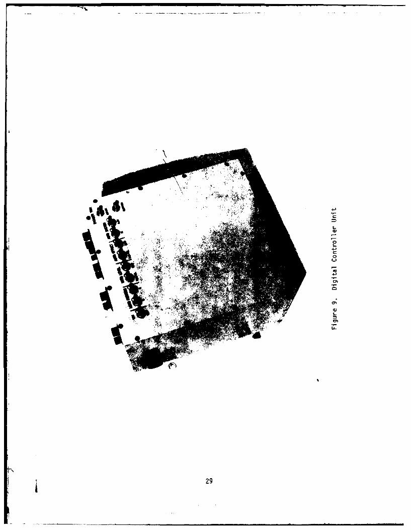
1. Digital Controller Unit
The AGLS digital controller unit (DCU) provides the system logic and control
necessary to perform the following functions:
o Receive commanded azimuth and elevation data from the GACS gun unit
o Monitor weapon azimuth and elevation data from the panoramic telescope
and M-15 quadrant
o Calculate position errors and generate correction signals to drive the
fire control instrument servos !
o Generate enable signals for the analog servos I
o Provide data to the display panels 1
o Monitor analog sensor null signals J
The digital controller unit is shown in Figure 9. p
I
. . . .. .
000
1. cu
LA.
29C

The digital controller unit processes signals from and to three separate systems:
GACS, AGLS analog and AGLS digital. Since each system has its own separateground point, ground isolation must be provided beweeen systems to prevent ground
currents and common mode noise signals. Optically coupled isolators have been
included at the GACS/AGLS digital interface as well as the AGLS digital/analog
interface, thus permitting each system to be grounded at its optimum point while
providing data flow between the systems. A block diagram of the instrument
controller unit is shown in Figure 10.
The DCU consists of seven printed circuit boards as follows:
a. Central Processor Unit (CPU)
b. Parallel Interface Adaptor (PIA)
c. GACS Interface
d. Dual Analog to Digital Converter
e. Multiplexed Analog to Digital Converter
f. Dual Digital to Analog Converter
g. Power Supply
Each of these elements is described in the following paragraphs.
a. Central Processor Unit -- The CPU board contains all the components for a
complete microcomputer system, requiring only power and an input/output device
to provide a working digital system. The board is a general purpose computer
board, containing a Motorola M6800 CPU, 4096 bytes of program memory (PROM), 4096
bytes of random access memory (RAM), two serial asynchronous interfaces (ACIA),
one parallel interface adaptor (PIA), a programmable timer, and address bus
drivers to interface the CPU to the remainder of the digital system.
The firmware, which determines the operating characteristics of the digital
system, is stored in four electrically programmable memory (EPROM) 2708 inte-
grated circuits. These circuits are mounted In sockets on the CPU board to
facilitate program changes during development. Temporary memory, used to store
30

i o 03 0 4
I TI-
0 40 -
<00o C4L 0 j.o ,~ (0 C-
UJ 0ul %t IfCDo 0o
00 ioll, t3.- CD
01 0 o - -C-L
OC a> > >>.J >J 40 1C3 '
z -w~
Ev +1+-I I-+-. V SAL-
-IlK
w K
R-$ 4 Z N;I- -A
L. IlCS
31

intermediate data while the program is operating, is provided by the random
access memory (RAM).
The ACIAs permit internal access to the CPU by keyboard or phone line for
troubleshooting. They are coupled through a cable to the external test connector
on the DCU. The timer is used to measure elapsed time for those program tests
with a time and magnitude requirement.
In the AGLS application, the CPU board is directly connected to the configuration
switch register by a separate cable and connector. The switch register permits
selection of program to select the level of automation under the control of the
test director. The switches are coupled to the CPU by the on-board PIA. The
remainder of the digital components are accessed through the PIA board.
b. Parallel Interface Adaptor -- The PIA board contains eight identical
Motorola 6820 PIA circuits, each accessing two 8 bit ports, or 16 lines of input
or output data, coupled through a ribbon cable to another interface board. An
address decoder is included on the PIA board, to indicate which of the PIA
circuits should be connected to the CPU data bus at any given time. The PIA board
essentially expands the 8-line CPU data bus to 128 lines of input or output data.The PIA board drives the display panels data bus directly through PIA circuit
number 8 (Figure 10).
c. GACS Interface -- The GACS interface board connects the output of the two
GACS 16-line command channels to the PIA board, using optical isolators to
separate the GACS and AGLS ground connections. The GACS output circuit permits
corresponding lines of the two channels to be connected to a single wire, as long
as only one channel is active at any given moment. Two optically coupledisolators are also provided to activate the GACS azimuth or elevation output,
under program control. The GACS data is coupled to PIA circuit number 1 (Figure
10).
d. Dual Analog to Digital Converter -- The dual channel analog to digital
converter board is used to interface the azimuth and elevation encoder trim
potentiometers into the digital system. A reference voltage of 10 volts is
supplied to each potentiometer. The potentiometer output is routed to a buffer
32

operational amplifier, a sample and hold amplifier, and then to the analog to
digital converter. The output of the eight-bit converter is connected to PIA
circuit number 6 (Figure 10). The circuitry is adjusted to yield a full eight
bit change in the output code thus permitting a trim range of + 12.8 mils for ten
turns on the potentiometer.
e. Multiplexed Analog to Digital Converter -- The multiplexed analog to digital
converter board accepts the analog error signals from the leveling servos and the
IR tracker, and sequentially converts each of these to a digital signal. The
digital signal is then transmitted through optically coupled isolators to PIA
circuit number 5 (Figure 10) on the PIA board. The CPU compares the digitized
errors to an acceptance level, to determine which status lamps should be illumi-
nated.
f. Dual Digital to Analog Converter -- The dual digital to analog converter
accepts azimuth and elevation errors calculated by the CPU, and converts them to
analog correction signals to be applied to the pantel and quadrant pitch servos.
The digital errors are provided by PIA circuit number 7 (Figure 10), optically
isolated, and stored in either the azimuth or elevation latch, under control of
commands from the CPU. The stored data from each latch is applied to its own D/A
converter, which generates an analog signal of up to + 10 volts full scale,
proportional to the input digital error.
g. Power Supply -- The power supply accepts +28 volt regulated power from the
system power supply, and converts it to the following dc voltages:
+5 volts - Logic supply
-5 volts - Logic supply
+12 volts - Logic supply
+18 volts - Encoder supply
+20 volts - Analog supply
-20 volts - Analog supply
+20 volts - Isolated analog supply
-20 volts - Isolated analog supply
33

The input direct current power is converted to alternating current by the in-
verter and then applied to a transformer with multiple secondary windings. The
output voltages are obtained by rectifying the various transformer voltages, and
then regulating the +5 volt, -5 volt, +12 volt, and +18 volt outputs. The +20
volt and -20 volt supplies are regulated to +15 volts and -15 volts on theindividual A to D and D to A boards, to minimize the effects of system noise and
provide more accurate reference voltages at each board.
2. Chief of Section Panel (COS)
The chief of section panel contains the operating controls for the AGLS, as well
as numerical displays of the commanded azimuth and elevation data from the GACS
gun unit, actual data corresponding to the counter readings of the M-117 tele-
scope and M-15 quadrant, and the respective errors between commanded and actual
values. The panel also contains status lamps to indicate acceptable leveling ofthe M-15 quadrant and M-145 mount, acceptable tracker to GACS RU lock-on (A/P),
and presence of the RU in the tracker field of view (XENON lamp). If any of theabove lamps extinguish, the No-Go lamp will illuminate. The chief of section
panel is shown on Figure 11.
This panel contains a control to adjust the display brightness, and a test button
to check proper function of all the display elements.
The following switches are located on the chief of section panel:
Power -- Activates the system power supply, digital controller unit,
all data displays, and certain other electronic assemblies.
Servos -- Activates those fire control instrument servos that have been
previously selected by the system configuration switches.
Weapon -- Activates the weapon azimuth and elevation servos if they have
been selected by the configuration switches, and if certain check con-ditions have been satisfied.
34
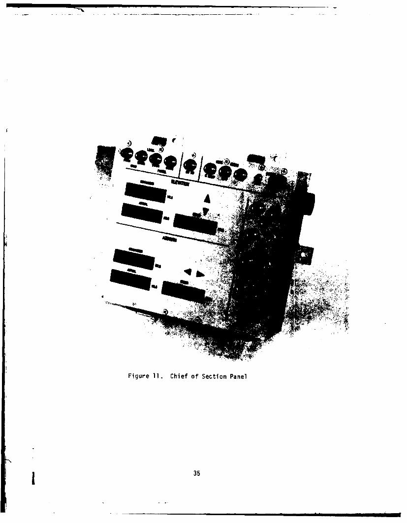
Figure 11. Chief of Section Panel
1 35

Load Position -- Selects either GACS elevation (down) or previously
selected load position (up) to be the command to the weapon elevation
servo.
RU Search -- Causes the panoramic telescope to slew clockwise (right) or
counterclockwise (left) to locate the GACS Reference Unit, if certain
conditions have been satisfied.
Data displays on the chief of section panel consist of the following:
Elevation Commanded Data -- The commanded elevation from the GACS gun
unit or the preselected load position.
Elevation Actual -- The elevation value displayed on the M-15 quadrant.
Elevation Error -- The difference between the two above values.
Azimuth Commanded Data -- The commanded azimuth from the GACS gun unit.
Azimuth Actual -- The deflection displayed in the upper counter of the
M-117 telescope.
Azimuth Error -- The difference between the two above values.
The panel accepts the above data in Binary Coded Decimal (BCD) format, trans- -mitted bit parallel, character serial from the digital controller unit. The
panel also contains a power supply which converts the regulated 28 vdc power to
+5 vdc required by the display electronics.
3. Gunner's Display Panel
The gunner's display panel accepts and displays the same azimuth data as is
displayed on the COS panel. This panel also contains a 28 volt to 5 volt
converter to energize the internal electronics. The gunner's display panel is
shown in Figure 12.
36V I.

Figure 12. Gunner's Display Panel
37

4. Assistant Gunner's Display Panel
The assistant gunner's display panel accepts and displays the same elevation data
as is displayed on the COS panel and contains a power supply identical to that
used by the gunner's display panel. The assistant gunner's display panel is
shown in Figure 13.
C. Gun Alignment Control System
The Gun Alignment Control System (GACS), developed and manufactured by Aviation
Electric Limited, is used by the AGLS to provide an azimuth reference. The GACS
consists of six assemblies:
1. Comnmand Post Unit (CPU)
2. Command Post Adaptor Unit
3. Converter/Adaptor Unit
4. IR Receiver
5. GACS Gun Unit
6. GACS Reference Unit
The GACS establishes an azimuth reference by using a rotating laser beam synchro-
nized to a flashing XENON lamp. Any GACS equipped gun can determine its azimuth
reference by directing its IR receiver, mounted on the panoramic telescope,
toward the reference unit. The GACS gun unit will count the pulses from the
XENON lamp and observe the rotating laser to measure the reference angle. The
command post unit will transmit, on manual command from the Fire Direction Center(FDC) fire orders to the GACS gun unit. The GACS gun unit will then compute the
required deflection by adding the reference angle to the commanded angle. The
resulting commanded deflection is automatically transmitted to the AGLS digital
subsystem. The GACS also provides a means of transmitting elevation data to the
AGLS, and fuse setter data to the GACS gun unit display. The GACS components are
described in the following paragraphs.
38

N C
Figure 13. Assistant Gunner's Display Panel
t 39

1. Command Post Unit
The command post unit accepts input data by manually set rotary switches. Data
to be transmitted consists of deflection, elevation, and fuse setting. After
data has been set in, it is transmitted by manually activating a pushbutton. A
flashing lamp indicates that data is being transmitted, and a steady lamp indi-
cates that the gun unit has accepted the transmitted data.
2. Command Post Adaptor Unit
The command post adaptor unit provides a means of coupling the command post unit
to either a phone line pair or a radio receiver-transmitter.
3. Converter/Adaptor Unit
The converter/adaptor unit, installed in the M-109, accepts the commanded data
from the phone lines or radio and couples the data to the GACS gun unit. The
converter/adaptor unit also contains a power supply to provide regulated
voltages to the gun unit and infrared receiver.
4. IR Receiver
The infrared receiver detects the flashing XENON lamp and the laser beam from the
reference unit, and transmits real-time electrical pulse signals as these events
occur. The IR receiver is mounted with the AGLS tracker on the panoramic
telescope, as shown in Figure 14.
5. GACS Gun Unit
The GACS gun unit accepts the pulses from the GACS infrared receiver to determine
the reference angle. It has the capability of adding the reference angle to the
commanded angle to compute the commanded deflection. It also has three data
display clusters, to display azimuth, elevation, and fuse setting. The azimuth
display can exhibit either commanded, reference, or normal angle as selected by a
three position switch. Also on the gun unit are two lamps, one to indicate
detection of the XENON pulses and, one, the presence of the laser beam.
40

II
orb
Figure 14. GACS IR Receiver and AGLS Trackerinstalled on M-l17 Telescope
41

6. GACS Reference Unit
The GACS reference unit contains a XENON lamp and a laser diode. The laser
rotates one revolution per second, and the XENON lamp flashes once for every 40
mils of laser beam rotation, and flashes twice as the laser rotates through
South. The reference unit can be energized by a 24 volt storage battery.
Initial alignment of the reference unit is accomplished manually by using either
a magnetic compass, or a monocular sight if a survey line is available. The GACSreference unit emplaced in a field situation showing the relationship to the
vehicle is shown in Figure 15.
D. Infrared Receiver
The AGLS infrared receiver detects the flashing XENON lamp of the GACS reference
unit, and provides a direct current positive or negative signal proportional to
the horizontal angular position of the XENON lamp in the tracker field of view.
The tracker is sensitive to lamp position in the horizontal axis for displace-
ments of 100 mils to the left and right of center, and will detect the lamp within
a + 100 mil vertical field of view. The tracker incldes direct current rejec-
tion circuits and an optical filter to reject ambient light, and contains an
automatic gain control to compensate for changes in range from tracker to refer-
ence unit. A one-bit digital output is also provided which indicates to thedigital controller that the tracker is detecting the GACS reference unit.
E. Weapon Control System
The weapon control subsystem consists of two channels, each consisting of an
electrically-operated proportional control servo valve, pressure operated engage
valves, an electrically-operated solenoid valve, a tachometer, and a controllermodule. The two controller modules and their power supply are contained in the
Weapon Azimuth and Elevation Controller Unit. See Figure 16.
1. Azimuth Control Subsystem
The azimuth control subsystem is shown in the block diagram of Figure 17. The
position error is detected by the infrared tracker mounted on the panoramic
42

II
L-
43-

4-)
S..4
-3
0
0
CL
-
44E

I w 4J
0 -. a00O
ao so
o 0j -
100 00
000 fl Iii>
-j-
.6 0
0!
2 LL
D)
0 0
07w
45

telescope head, and supplied to the azimuth controller module. The module
filters the error signal to obtain the desired frequency characteristic,
combines the position signal with the tachometer velocity signal, and generates
an output error signal to operate the azimuth servo valve.
Hydraulic fluid from the M-109 power pack is filtered and then applied through
the azimuth solenoid shut-off valve to the servo valves, and also to the pilot
ports of the pressure-operated engage valves. The engage valves will close upon
removal of supply pressure, to disconnect the servo valve and permit normal
azimuth control with the gunner's control handle. With hydraulic supply pressure
applied, the servo valve will apply hydraulic flow to the azimuth hydraulic motor
in proportion to the electrical current from the controller module. Direction of
hydraulic flow is determined by the polarity of the control current. Pictures of
the filter, solenoid shut-off valve and servo valve assembly are shown in Figures
18, 19 and 20 respectively.
The hydraulic motor rotates in response to the servo valve flow, thus rotating
the cab to control weapon azimuth. If the panoramic telescope is also being
driven, as is the case with the automatic azimuth configuration, the tracker will
be driven away from the GACS reference unit, thereby generating a position error
which continues to drive the weapon in azimuth until the telescope has reached
its commanded deflection. As the telescope comes to rest, the cab will continueto rotate until the final position error, as measured by the tracker, has been
reduced to zero. As the weapon approaches its commanded position, the telesocpe
mount will be automatically leveled and thus the mount will insert an azimuth
correction which compensates for weapon cant by deflecting the telescope line-
of-sight. This correction then is automatically inserted as the weapon comes to
rest.
A tachometer is utilized to provide a signal proportional to azimuth velocity.
This velocity error signal is needed to provide an indication of azimuth
velocity, so that the cab will rotate at the proper speed, as the cab and
telescope both are driven in the Automatic Offset mode. The azimuth velocity
signal is also used as a prediction signal to improve azimuth stability andprovide for smooth deceleration as the weapon approaches the final position after
a large change in azimuth. A picture of the tachometer is shown in Figure 21.
46

Map
II
Figure 18. H~draulic Filter Assembly
I 47

Figure 19. Azimuth Solenoid Shut-Off Valve
48

Figure 20. Azimuth Servo Valve Assembly
I4

Q)
4J
4-)(A
4-)
CL
.4-i
at
500

2. Elevation Control Subsystem
The elevation control subsystem, shown in the block diagram of Figure 22, is
similar in operation to the azimuth control subsystem. The position error is
detected by the level sensor mounted on the M-15 quadrant pitch axis and is
supplied to the elevation controller module. Hydraulic pressure to the elevation
engage valves is applied or removed by the elevation solenoid shut-off valve.
The elevation engage valves will close on removal of supply pressure, to discon-
nect the servo valve and permit control of weapon elevation by either the power
control handle or by the manual hand pump. With hydraulic supply pressure
applied, the elevation servo valve will control pressure to the elevating
mechanism in proportion to the electrical current from the elevation controller
module, and polarity of the pressure is determined by polarity of the control
current. Pictures of the solenoid shut-off valve and servo valve assembly are
shown in Figures 23 and 24 respectively.
As the weapon elevates, the quadrant may also be driven away from level, thus
generating a position error which continues to drive the weapon until the
quadrant has reached its commanded elevation. After the quadrant reaches the
comanded elevation, the weapon will continue to elevate until the position error
measured by the level sensor approaches a null, thus indicating that the weapon
has reached the proper elevation. As the weapon approaches its final position,
the quadrant cant servo is also leveling the quadrant in cant, so that the cant
correction is already implemented when the weapon comes to rest at the commanded
quadrant elevation.
An elevation tachometer is also provided to generate an elevation velocity error
signal. This signal is needed to limit the elevation velocity to a controlled
value during large changes in elevation, by providing additional feedback which
essentially reduces the influence of the position error signal. The velocity
error signal also provides for smooth deceleration and enhanced stability as the
weapon comes to rest. A picture of the tachometer in the installed position is
shown in Figure 25.
51
- -m m mmmmm m • mmm m _ m_ _ m-

00
3
4 I4Jz 0l
-0 -
loo2 000
000u 0
w 00 la
4z II
laB-
0I~ir se "i3-) 1-

I1
EU
II-4-0
4-,
-c
0Cw0
C0
4-,EU
LjJ
CJ
GJL.
La~
53

0
-)>)
4A L0,
54C

CL
to 0
S
IL-
55C

F. System Power Supply
The AGLS system power supply receives +24 volt power from the voltage support
battery, and generates the following regulated power:
o +32 volts dc
o -32 volts dc
o +28 volts dc
The positive and negative 32 volt supply is capable of delivering a total of 10
amperes from either or both outputs. These voltages serve as the power source
for the five servo amplifiers in the instrument servo controller unit. The
positive 28 volt dc supply is capable of delivering 5 amperes and is the power
source for the digital controller unit, the chief of section panel, and the
gunner's and assistant gunner's display panels. A picture of the power supply is
shown in Figure 26.
The power supply, shown in the block diagram of Figure 27, consists of two
switching regulators, each controlling power to an inverter, with a common fre-
quency source. Input power from the voltage support battery is applied through a
manually resettable circuit breaker to a power relay. The power relay, con-
trolled by the power switch on the chief of section panel, applies power to the
two switching regulators and serves as the means of energizing or de-energizing
the AGLS subsystems.
The +28 volt regulated output power is controlled by two semiconductor power
switches on assembly Al (Figure 27). The input power is filtered and applied to
the power switches. Each switch is either completely on or off. For example,
when power switch U1O is on, current flows from the input filter through U1O, the
inductor Li and the current monitor resistors to the 28 volt inverter A4. When
the switch U1O shuts off, the current flows through diode D10 through Li to the
load. The switching regulator controls the output voltage to the inverter A4 by
adjusting the percentage of time that U1O is conducting. Switches U1O and Uli
are essentially in parallel, and the current in each switch is monitored by the
current shunt resistors R124 and R125. The pulse width modulator adjusts the
conduction times to equalize the current in each switch.
56

I0~
0.0
0OL
CL
V)
4-
di.
LL.
57

C) 0, U
W CZ
W W
or J
0 0 JJ -
t0 0 a
Lm N j
Lu..
U,-
O0WO UrI
I 58

The output currents from switches U1O and UI are combined, and then applied toinverter A4 consisting of transistors Q16 and Q17 and transformer TI.
Transistors Qi6 and Q17 are alternately driven on and off each for slightly less
than 50 percent conduction ratio. Since the two windings on transformer TI are
equal, the inverter essentially doubles the switching regulator output to obtain+28 volts output for +15 volts switching regulator output. The regulated +28
volt output voltage is attentuated by the scaling network, and then compared witha reference voltage. The difference is amplified by Ui and applied as the inputto the pulse width modulator. Thus, the switching regulator conduction time is
automatically adjusted to maintain a constant output voltage as input voltage and
load change.
The current monitor inputs will override the error voltage from Ui if either
switch current exceeds 6.0 amps, and will then limit the switch currents to 6.0
amps each, regardless of load resistance. This will limit the short circuit
current to 6.0 amps in the event of a regulated 28 volt overload, and prevent
further system damage.
The + 32 volt power supply is similar to the +28 volt supply, except that four
power switches, UI2, Ui3, UI4 and UI5 on assemblies A2 and A3 are connected inparallel to provide the current to inverter A5. Inverter A5, consisting of
transformer T2 and transistors QI8 and QI9, multiplies the switching regulator
output by a factor of 2.5, and provides isolation of the analog system groundwith respect to the M-i09 power ground. Feedback voltage is taken from the
transformer, rectified, filtered, and compared with the reference voltage. The
difference is amplified and applied to the 32 volt pulse width modulator to
control the conduction ratio of the power switches. As in the +28 voltregulator, current is measured by the current monitors R126, R127, R128 and R129
to balance the load in each switch. The monitor signals also limit each switch
current to 6.0 amps, thereby providing a limit of 10.0 amps on the total +32 and-32 volt supplies to prevent power supply damage in the event of a system
overload or short circuit.
All control logic for the switches and Inverters is provided by the two circuit
boards A6 and A7. The sequencer (A6) contains the master clock for the switching
regulators, and the drive amplifiers for both Inverters. The regulator assembly
L 59

A7 contains the control amplifiers for both basic power supplies, and the modu-
lators and drivers for all six power switches. Input and output power filters
are included on the individual assemblies to minimize the electrical noise from
the power switches.
1I!!
II
60 3

V. DESIGN STUDY
A. Theory of Operation
1. Methodology
The Automated Gun Laying System, shown in block diagram form in Figure 1, isconfigured to perform the same fire control functions as are now performed
manually. These functions are enumerated below:
1. Level telescope pitch
2. Cross level telescope
3. Level or offset quadrant cant
4. Cross level quadrant
5. Offset telescope
6. Drive weapon azimuth
7. Drive weapon elevation
Basically, the methodology employed in automating the M-109 was to retain the
existing fire control geometry, to add sensors in parallel with the existing
sensors and to add actuators in parallel with the existing manual controls. Asan example, the cant level axis of the M-15 quadrant is shown in the blockdiagram of Figure 6. The basic quadrant is cross leveled by the assistant
gunner, who rotates the cross level knob while observing the spirit vial whichtells him in which direction to turn the knob. In automating this axis, a levelsensor is attached to the level vial, an electric servo motor is coupled to theknob through gearing, and a power amplifier converts the level sensor outputvoltage to a current sufficient to drive the motor.
2. Fire Control Servos
All of the fire control servos can be represented by the basic block diagram ofFigure 28. The basic servo system utilizes the concept of inner loop velocity
feedback, with a tachometer closely coupled to the actuator to accurately measure
61

)
-JL
V) 0j0 D
o U)
I-
CD.w0LA-J
V) C.)
C )
I 0D
LLJ0 LI-
CDa &n
CD
CD u)
62

actuator movement while minimizing the effects of backlash and mechanical com-
pliance.
The drive torque for each axis is provided by a motor-tachometer, shown in Figure
29, consisting of a direct current torque motor, with a dc tachometer closely
coupled on the same shaft. A motor was selected which had sufficient power to
drive each of the instrument servos, as shown in the listed requirements of Table
I. In the two quadrant and two telescope mount axes, a gear ratio of 20 to 1 was
used, and a ratio of 10 to I was used in the telescope azimuth axis. Although the
gearing did increase the mechanical complexity of the servo drivers, it did
permit use of a much smaller and lighter motor, thus resulting in less total
actuator weight.
The motor and tachometer are coupled by a steel shaft with no linkages, thus the
only dynamic element separating the motor and tachometer is a torsional
resonance, estimated to be in excess of 10,000 Hertz. The remaining dynamic
effect is the simple first order expression for a dc motor, with a time constant
determined by motor inertia, torque constant, and armature circuit resistance.
Actual motor-tachometer data from the quadrant cant axis is shown in Figure 30,
and does exhibit the predicted dynamic performance. With an actuator and feed-
back sensor exhibiting dynamic characteristics approaching the ideal, it is
possible to utilize high gain in the inner servo loop. The inner loop con-
trollers, identical for all five fire control servos, can then control motor
shaft rotation to achieve very low residual error in response to the outer loop
sensor.
While the tachometer provides the short term corrections for actuator control,
the outer feedback loop is used with a position sensor to drive the system to the
desired null position. The outer loop then can be considered as a trimming
control, which monitors the at-rest position, compares it with the conmanded
position, and applies a correction signal to drive the inner loop and ultimately
correct the load position.
63I

'-'S.3
C3
0
IP)
L>
64~

......
TABLE I
Fire Control Instrument Servo Performance Parameters
Calculated CalculatedRequired Knob Torque Knob Speed
Load Torque . Required @ Gear Ratio @ Load TorqueA Servo Axis (Maximum)--, Load-Speed IGear Ratio (Maximum) (Maximum)
Telescope 150 RPM 161.6 RPMAzimuth 9.0 lb-in 125 mils/sec 10:1 46.9 lb-in 134.7 mils/sec
I Mount 57 RPM 73.3 RPM
Pitch 25.0 lb-in 40 mils/sec 20:1 93.8 lb-in 51 mils/sec
!Mount 71 RPM 87.2 RPM* Cant 12.0 lb-in 40 mils/sec 20:1 93.8 lb-In 49 mils/sec
Quadrant 60 RPM 78.7 RPMPitch 20.0 lb-in 100 mils/sec1 20:1 93.8 lb-in 131 mils/sec
Quadrant 60 RPM 80.8 RPMCant 18.0 lb-in 100 mils/seci 20:1 93.8 lb-in 135 mils/sec
1 65

0) 0) 0 C0 0 0Co' - ' C14 c'S30 C---- d-nm
I -- --
7 -. I I . , 4 J
5 . -- ---.. .. 06
I--
.4..
*~ 7 -j9!
I _ _ _T 1C) 0
-. 4J
3. . . .
CI
L
70
1- a %0 1
7 - _
4,0 O______
to co 0-
(3(qp) apnltubeW U.C'
66

j 3. Position Sensors
Three different types of position sensors are used in the AGLS fire control
servos, depending on the system requirements of the particular servo. Level
sensing is accomplished with accelerometers, shaft position is measured with
digital encoders, and the position error of the panoramic telescope is measured
with an infrared tracker; each of these is described in the following paragraphs.I
a. Level Sensor
Level sensing is accomplished by a GG326 accelerometer built by Honeywell
Avionics Division. This accelerometer is mounted with its sensitive axis in thehorizontal plane, parallel to the level vial of the axis to be leveled. In this
orientation, the accelerometer senses local gravity, and will provide a positive
or negative dc signal proportional to the angular displacement from level.
Figure 31 is a schematic view of the GG326 Accelerometer.
The pendulum and torsional suspension is fabricated from quartz fiber. A thin
coating of metal is vapor-deposited over the length of the suspension and pendu-
lum, providing a conducting surface. The base of the pendulum is positioned in a
permanent magnet field so that current flowing in the pendulum circuit acts as a
one-turn torque generator.
The optical pickoff consists of a miniature tungsten filament lamp and a silicon
pn junction photodiode. The p-layer of the photodiode is divided into equal
parts with a 0.003 inch separation. At the null position, the base of the
pendulum coincides with the slot In the photodiode.
An acceleration input will cause the pendulum to deflect from the null position,
increasing the amount of light incident on one-half of the photodiode while
decreasing the light on the other half. The light unbalance produces a differen-
Itial voltage signal at the output of the photodiodes. The photodiode signal is
amplified and fed back to the torque generator in the proper phase to restore the
[pendulum to the null position. The rebalance current is directly proportional to
the input acceleration and is converted to a voltage by a series resistor.
667.1

LAMPTORQUER MAGNETS
A[ VAPOR-DEPOSITED1~C ONDUCTING FILM
~~PENDLUM
Figure 31. Schematic Diagram, GG326 Accelerometer
68

A significant feature of the GG326 accelerometer is the low elastic restraint of
the quartz fiber suspension. This restraint is 0.5 g/radian (g/rad), compared to
2 to 3 g's/rad for metal flexure pivots or torsional suspension. Since the dual
photodiode is fabricated from a single silicon chip, the output voltages of the
two halves closely track with temperature. Any photodiode deviations have a
small effect on accelerometer null bias due to the low elastic restraint.
The pendulum assembly is mounted in a hermetically sealed aluminum housing. The
j housing is filled with a low viscosity silicon fluid to control the dynamic
characteristics of the accelerometer. The electronics assembly is designed to
accept the terminals from the sensor and is bonded directly to the sensor
housing. A hermetically sealed cover over the electronics assembly provides the
electrical terminations for the accelerometer, as well as the protection against
humidity and other destructive environments.
Since the accelerometer will sense lateral acceleration as well as the accelera-
tion of gravity, its dynamic characteristics must be considered. The accelero-
meter is considered to be off the axis of rotation for a given leveling applica-
tion, by a distance R. This displacement includes physical distance due to
design constraints of the fire control instrument, internal displacement of the
sensitive element of the accelerometer from its mounting face, as well as un-
knowns in the actual location of the rotational center. The relationship of
accelerometer location with respect to axis rotation can take four forms, as
shown in Figure 32. In all cases, the rotation 9 is considered positive when
rotation is in the counterclockwise direction.
In form (a), the accelerometer output Va is equal to
SVa = Ka (gsin 9 + R- d )dt 2
where the first term is due to the angular deviation from level when the acceler-
j ometer is at rest, and the second term is due to lateral displacement when the
axis in question is being rotated. There will also be a centripetal accelera-
tion applied to the accelerometer in a direction toward the center of rotation,
but this term will not cause an accelerometer output since it is not in the
*direction of the sensitive axis.
I 69

- .- Center of Rotation
R
Accel1eromneter
(a) (b)
0I(c) (d)I
Figure 32. Accelerometer Locations
70I

The accelerometer will be used in a nulling application where the angle gissmall, thus permitting the approximation sin 9 = 9. Then the expression for the
output V can be further reduced toa
Rgd29Va = Ka (g 9 + Rd-2t9Va Ka 0 +
dt
In Laplace transform form, the above expression becomes
Va(S) R S2
)= Kag(1 + 9
For S = j ,it can be seen that the above transfer function is equal to Kag for
much less than , and is equal to -KaR 2 for much greater than 2. At
= + ,the transfer function goes to zero. This transfer function thus contains-RIa pair of complex zeros at = + The leveling loop frequency response
- Rmeasured during the accelerometer placement study, shown in Figure 33, is repre-
sentative of the complex zeros as derived above.
Form (c) accelerometer placement will result in a similar expression, with both
signs negative.
The transfer function of a form (b) accelerometer placement is:
R~d2g9Va = Ka (g sin - d--- )
dt
which when reduced becomes:
Va(S) R
-0 = kag (1 - S
This transfer function, for much less than * , is equal to Kag, as in form
(a). However, for much larger than # , the transfer function becomes +KaR 2
and does not change sign as form (a) did. The roots of this expression are real,
at = + . The frequency response of Figure 34 is an example of thisconfigura-
tion.
71

1onc a, ,C*0 0~
60. __ __ 1 __ _ - ._____ L __ __ __ _
LAJ
Ln CD
%0- . .
cc
In~~~~~~~u 1u__ _ _ _ _ _ _ _ _ _ _ _
'0 9 ____ ______________ _Of
=_7
LII
24 L'~ -l
a-. -a)-T -, -. -
LLi_____ _ ___ C-
x ~ . -
m-
3 _____ ____ __ ____ ______ ______ __ __7
'00 T j enC) 4
F U-
72

C) CD CDC C) C:) C)ON CDj CDi CDj C\ ,)cz n
100
t ~LL
c~C)
Is. . . . .. .
o -.-
__ _ _ ___ _t_ _ _ _ _ _
5 ------ _ _ _ _ _ _ _ _ _ _ _
-~ I-U! -L7 . ... *
.,~ _______ _____________________,
LD ___
[1 7: C_
_ _ _ _ _ _
I~ 6: . __I. _ ___ ____ ____
~~~~'~~~ 5 r_ _ _ _ _ _ _ _
4(-
3 -____ -______ ______ ______ _____
C0 0o ('.J % l coe%j
(Cmpl 1pr ititipimI I
73

1Form (d) accelerometer placement will result in a similar expression, except with
reversed polarity.
Thus, it can be seen that the dynamic response of each servo mount can be
affected by the location of the accelerometer. Additional factors affecting
servo response include the inertia and compliance of each of the individual servo
axes. Thus, a different set of compensation networks is needed to accommodate
the dynamic characteristics of each of the five instrument servos.
b. Encoder
In the automatic offset mode, the telescope azimuth servo and the quadrant pitch
servo must be driven to a given deflection, as indicated by their respective
mechanical counters. To sense the actual deflection of these instruments,
digital encoders are coupled to the input shafts through precision gears. It was
determined that the input knob scale factor will be 100 mils per turn for the
quadrant, and 50 mils per turn for telescope.
The required range of operation is zero to 6399 mils, and it was decided to
measure in 0.1 mil increments to achieve good system accuracy, resolution, and
stability. Thus, an encoder was needed that had a full count capacity of 0 to
63,999. Vendor surveys revealed that the best method of achieving the required
count range in an acceptable size was to use a two-disk encoder.
The encoder used in the AGLS has one disk driven directly by the encoder shaft,
and a second disk driven by gears. The direct or high speed disk measures one
complete shaft revolution as 1000 counts, while the slow speed disk advances one
count for every input shaft revolution from zero to 63. After reaching a count
of 63, the slow speed disk advances to zero. The data output from the slow speed
disk is synchronized to the data from the high speed disk so that all numbers
change state at the same time. As an example, when changing from 599.9 to 600.0,
the hundreds digit (5 or 6) will be generated by the slow speed disk, while the
other digits (99.9 or 00.0) will be generated by the high speed disk. The
synchronizing circuitry will prevent the number 699.9 from being output during
the transition from 599.9 to 600.0 if backlash or mechanical errors should exist jwithin the encoder.
7
74I i

The encoder data is accepted by the digital controller unit, and used to deter-
mine magnitude and polarity of the correction signal to be applied to the instru-
ment servo. The encoder data is also applied to the digital displays, to
indicate actual quadrant and telescope counter readings.
The digital controller unit uses simple arithmetic to subtract the encoder value
from the input commanded value, except that the error is checked to determine
whether it is larger than 3200 mils. If larger, the error is subtracted from
6400 mils, so that the weapon is always driven to null by the shortest path. The
digital value is then converted to an analog signal. All servo compensation and
control manipulation is performed by the analog servo subsystems.
c. Infrared Tracker
The infrared tracker detects the flashing XENON light from the GACS reference
unit, and provides an analog output voltage proportional to the displacment of
the XENON lamp from the center of the tracker field of view. The AGLS tracker
shown in Figure 35, consists of three major subsystems; the optics, the sensors
and the electronics.
Optics
The optical system utilizes a 50.8 millimeter focal length, 50.8 millimeter
diameter Fresnel lens to gather the XENON energy and focus it on to the detector.
An optical filter with a passband from 820 to 893 nanometers at 50 percent
transmission is placed between the lens and the sensor to reduce the ambient
light level while permitting the infrared energy to pass through. Reducing the
ambient light level will correspondingly reduce the ambient current through the
sensor, and will help to minimize the noise output.
Sensor
The sensing element of the IR tracker is a lateral effect photodiode, shown in a
cross section in Figure 36. The scene, including the XENON lamp, is focused on
the sensor. For purposes of information, assume that the scene is not present
and that only the lamp is visible. When the XENON lamp flashes, the photons from
| 75

$
I
L
U
LI-
I-.
4,,~.1CD
I',
4~, IL
LL tIIII
76
I
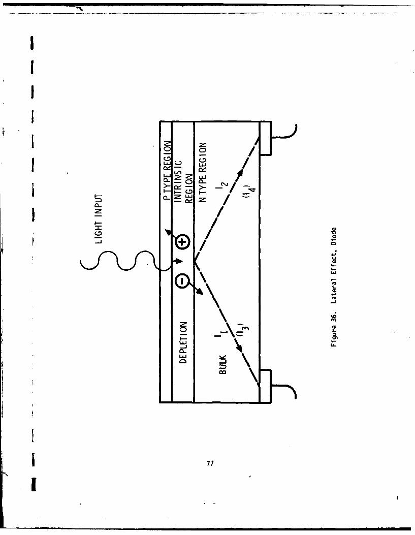
-= - ___
0A Ln /~0
0 ~LLJ
~ / 4-
-i-
77U

the lamp image generate electron hole pairs in the depletion region. Holes are
attracted to the P-region and annihilated in the gold film, while the electrons
are injected into the high resistance bulk silicon N-region.
The electrons travel to the two back contacts as a function of the distance to
those contacts. For a point image located L distance from one edge of the
sensor L distance wide, the current out of the reference contact will be (1 - )I, and the current out of the other contact will be I, where I is the total
current. The difference signal will be
I = 1(1-2 ) IThe sum signal is equal to I, the total current, which is equal to the total
current generated due to the XENON lamp energy. If the difference signal is
divided by the sum signal, the resulting signal
is= 1-2
is independent of XENON energy.
If the scene is now focused onto the detector, the difference signal will repre-
sent the centroid of brightness. The signal from the scene will be present as a
steady or slowly changing bias upon which the XENON pulses are riding. Since the iscene energy can be orders of magnitude larger than the XENON energy, this bias
must be removed.
The electrons generated by the photon energy are generated by a linear process. I
That is, there is a fixed ratio of optical energy to current flow, and this
relationship holds for many orders of magnitude. The gain of the Schottky sensor 1used in the AGLS tracker is approximately 0.4 amps per watts at the XENON IR
wavelength. The linear responsivity of the detector permits detection by removal Iof the ambient signal.
As discussed above, the difference signal should be divided by the sum signal to jnormalize the tracker output. However, divider circuits usually exhibit
problems in linearity, offset and frequency stability. The Automatic Gain f78
amidadl 1 •Id l d I li

Control (AGC) technique used in the AGLS tracker is to process both the differ-
ence and the sum signals, and to multiply both signals by the same gain. The
resulting sum signal is then compared with a reference voltage and the difference
is used to adjust the gain of both channels. The sum signal is thereby kept
constant over varying range and XENON light output. The difference signal output
then becomes
Is = 10 (1-2)
where Io is a constant.
Electronics
The tracker electronic circuitry shown in the block diagram of Figure 37, accepts
the two sensor signals, corrects for ambient light and changes in XENON energy,
and generates a positive or negative direct current signal proportional to the
XENON position. The major circuit elements consist of the preamplifier, the
switched AGC, the integrator, the sample and hold amplifier (S/H), the variable
AGC, and the output amplifier, as described in the following sections.
Preamplifier
The basic tracker performance limiting characteristic is the fundamental noise
of the preamplifier. Discussions with the sensor manufacturer and contractor
engineers who have had experience in low noise amplifiers have verified this
conclusion. Because of the low power level of the XENON lamp, the effect of the
noise will be an increased tracker output noise, or jitter, as range from tracker
S to XENON lamp is increased. The preamplifier consists of a high gain, high
frequency amplifier, and a means of removing the dc and low frequency components
o of the sensor output. The dc component results from the ambient light of the
scene, caused primarily by sunlight. Some of this energy can be reduced by use
of the optical bandpass filter. However, there will be steady state light energy
in the wavelength of the XENON flashes, so dc removal circuits must still be
included.
7f !79

~~0-
c0
w z
W aL :
LL MLL C)< 0
w
w w
40 0
Ar,00
0 ix
zz
CLL
Uw
6\ 80

IBy choosing the frequency at which the dc removal circuit is not effective, low
frequency rejection is also achieved, thus reducing sensitivity to moving bright
4 spots in the scene. Low frequency rejection also reduced the bandwidth which
reduces the overall noise of the preamplifier.
The preamplifier shown in the schematic diagram as Figure 38, consists of two
transconductance amplifiers UI and U2, a difference amplifier U3, and a sum
amplifier U4. The transconductance amplifiers change the current outputs of the
sensor to voltages which can be further processed. The two outputs are sub-
tracted by U3 to obtain a difference signal, while the two outputs are added by
U4 to obtain a sum signal.
The transconductance amplifiers each consist of a second order low-pass active
filter. While it might appear that a short pulse would be "lost" in a low pass
amplifier, it must be noted that the low pass amplifier will output a pulse equal
in volt-time integral to that of the input pulse, times the gain of the circuit.
Since the integrator will determine the integral, nothing in the signal is lost
by going through a low pass filter. However, reducing the magnitude of the pulse
will permit more gain to be used in the preamplifier, thereby, reducing the noise
effects of the remaining circuitry. The integrator gain can be reduced to
maintain the same overall gain. But the most important improvement is the
reduction in bandwidth, which will reduce the value of the root mean square (rms)
noise of the circuit.
To accomplish dc rejection, the output of transconductance amplifier U1 is low-
pass filtered to remove the XENON pulse signal and detect the remaining steady
state or slowly varying signals. The signal is then amplified by the dc rejec-
tion amplifier U5 and converted by R1 to a current which essentially cancels the
steady state input current from the sensor. The same process is used by ampli-
fier U6 and resistor R21 to remove the ambient signal from the output of ampli-
fier U2.
The outputs of amplifiers UI and U2 are then subtracted and amplified by differ-
ence amplifier U3. Amplifier U4 accepts the U1 and U2 outputs, and amplifies the
sum of the two. The sum and difference outputs are then applied to the switched
LAGC amplifiers.
1 81

- r f
- E-=
0-- c-
or'
'c9
>' > WC
fa
P4
4
7-
I E
cc cc
- II --
(n
82

AGC Amplifier
Two concepts for AGC were considered. A digitally selected gain control which
would change gain by selecting sets of input and feedback resistors, or a solid
state multiplier which would multiply the pulse by a dc control voltage.
The digital AGC is more accurate, but would not provide sufficient resolution.
For example, a gain range of at least 100 to 1 is needed. If performed in
geometrically uniform steps, two amplifier sets with four gain steps per set
could achieve the gain range with a step ratio R, where:
R = 40 db - 2.5 db16 steps
or
R = 1.333
Thus, an AGC resolution error of +16% could be expected using the completely
digital AGC. The solid state multiplier approach would be a less complex circuit
and would have essentially infinite resolution. However, the basic accuracy of
the multiplier over a dynamic range of 100 to I may affect the tracking of the two
AGC amplifiers. It was then decided to utilize both switched and continuously
variable AGC, to benefit from the advantages of each approach. A total gain span
of IX to lOOX is needed to a 50 to 500 meter range. To accommodate such a large
span, a switched gain amplifier having gains of 1, 4, 16 and 64 is the primary
gain control amplifiers, and an analog divider will be used to achieve better
resolution over a limited span of approximately 6 to 1.
The switched amplifier, shown in Figure 39, uses a programmable amplifier (PRAM)
consisting of four preamplifiers which are selected by digital control of the two
address lines. Each preamplifier is connected to a resistor network to provide a
specific gain. A given digital value on the two address lines will select a
certain preamplifier, and thus provide the desired gain. The digital values are
j established by a separate control circuit through interaction with the linear AGC
amplifier.
I| 83

Ix > 3 >LA 0 tA+ w I
F n 0%
z I" ol
- N
- - eJ NI
aJ1
<o
ui 4J.
acr.
N r4
- 0
z
84

I
Integrator
The following description of the integrator for the sum channel, shown in Figure40, will also apply to the difference channel, since the two circuits are iden-
tical.
The sum signal is applied through capacitor C1 to the quad switch S1. Prior tothe start of the XENON flash, terminals 1 and 2 are shorted to connect the outputside of C1 to the ground. This causes C1 to charge to the direct current (dc)level of the sum signal. This voltage will then be subtracted from the video
signal, effectively removing any remaining dc bias from the input signal.
To ensure that the integrator, U1, begins its integration at zero volts,terminals 8 and 9 are shorted, providing feedback around the integrating capa-
citor, C2.
When a XENON flash occurs, the sum signal initiates the timing and logic neces-sary to operate the switch drivers. The first step is to open contact 1 to 2, and
8 to 9, and to close contact 3 to 4. The signal then flows through to theintegrator input resistor RI, and the signal is integrated for the selected time
duration. The second step is to open switch contacts 3 to 4, and close contacts10 to 11, thus applying a zero input to the integrator for a hold period. Duringthis time, the integrator output is sampled by the sample-and-hold circuit.
After the sample has been stored, the contacts 10 to 11 open, contacts 8 to 9
close to reset the integrator, and contacts 3 to 4 close to restore the dc inputlevel. The circuit is now ready to accept another input pulse.
Sample and Hold Amplifier
A sample and hold amplifier is used to accept the integrator output and to store
this signal until the signal from the next pulse has been measured. The smIland hold output is then a continuous dc signal, with step tranition% '0 ttracker should be moving with respect to the reference 6ait.
-,
!

AD0A097 521 NDNEYWELL INC MOPAINS M EFEgNSE SYSTEMS DIV F/6 19/6AUT00ATED SUN LAYING SYSTEM FOR SELF-"OPLLED ARTILLERY MAPON--ETCUNCLASSIFIED MAY 80 9 £ LEHTOLA, K A HERZINS DAAAOO-7?-C-OZsI
mmhmmlllllllllIIIIIIIIIIIIIlIFIIIIIIIIIIlIIIIIIIII
IIIIIIIIIII 0L o BIIIIIIII

B~H illILO
11.5 11 1.4 11111__.6
MICROCOPY RESOLUTION TEST CHIARTNtII(}NA[ JIN L I A1,111I I.

LJ
Q
4-
d)
5-
I-)-w
InI
M A-i =D Lm86

Continuous AGC and Output Filter
The sum sample and hold output is then applied to a pulse-modulated switch which
either passes the signal when ON, or blocks the signal when OFF. The ON to total
period ratio is under control of a pulse width modulator. The average output of
the switch is then
e w=tonesw -Tx eS/H
where es/w average switch output voltage
eS/H = sum sample and hold output
ton = on time of the modulated switch
T = period of switch frequency
The switch output is filtered and subtracted from a reference voltage, and the
difference is amplified and applied to a pulse width modulator. Since the pulse
width modulator controls the switch conduction time ratio, a closed loop exists
to maintain the sum signal at a constant value. The same conduction time ratio
is then used to modulate the difference sample and hold amplifier, to adjust the
difference signal for changes in XENON intensity. The switched multiplier con-
trols over a dynamic range of about 6.0 to 1.0.
The control scheme is to amplify both the sum signal and the difference signal by
the same gain, and to integrate both signals by identical circuits. The sum
sample and hold signal is then monitored if it is lower than 1.0 volt, the
digital address is advanced one count increasing the gain by a factor of 4.0.
After a short time delay, the sum signal is rechecked. If it is still less than
1.0 volt, the count will be advanced again, and rechecked. The process will
continue until the sum signal is in the acceptable region, or until maximum gain
has been reached. The reverse process is applied if the sum sample and hold
signal is too high. In this case, if the signal is more than 6.0 volts, the gain
address is reduced one count, which causes the switch AGC amplifier to reduce the
gain by a factor of 4.0. The range of acceptable input voltage has been estab-
lished as greater than 4 to 1 to avoid oscillations which might otherwise occur
8
| 87

if the sample and hold output should be close to the threshold value, and thus
alternately advancing and retracting the gain by one count.
The difference sample and hold signal, after being multiplied by the AGC conduc-
tion ratio, is then amplified and filtered by a 5 Hertz active filter. The
resulting tracker output is then transmitted by wiring harness to the Instrument
Controller Unit.
Sequencer
A sequencer circuit is included to trigger the integrators and sample and hold
amplifiers in response to the leading edge of the XENON pulse. A digital output
from the sequencer also indicates when no pulses are being detected. This one-
bit output is used by the Digital Controller Unit to determine what control mode
should be permitted or implemented.
A timing diagram for the tracker sequencer is shown in Figure 41. Since the
tracker, mounted in the M109, does not have any electrical connection to the GACS
reference unit, the tracker must synchronize itself by detecting the leading edge
of the XENON pulse. This is accomplished by applying the sum amplifier pulse
output to the comparator and then to a series of six monostable multivibrators.
Time T0 is triggered by the sum amplifier output pulse, which then triggers TI.
During time To the integrator reset switch 8-9 and the input dc restoration
switch 1-2 are opened, and they are both closed during the remaining time.
During time TI, which envelopes the XENON pulse, the switch 3-4 is closed to
apply the sum and difference pulses to their respective integrators. At the end
of time T1 , timer T is triggered to actuate the switch 10-11 which holds the
integrator input to zero, and to enable the sample and hold amplifier. After T2
goes low, the sample and hold switch opens, but the integrator output is held to
assure no S/H loss while the switch is opening. When To goes low, the integrator
resets, and the dc restoration of the input coupling capacitor is initiated.
Timer TS, also triggered by the leading edge of To , is used to block further
trigger inputs to timer T for approximately 4 milliseconds. This will prevent
the tracker from being triggered by bright flashes that are not synchronous with
the 160 Hertz XENON lamp.
88,

SumSignal
To-i
TT8

Timer T3 is triggered from the trailing edge of T1 , and is used to clock the
address counter for the switched AGC amplifier. The trailing edge of the T3
pulse triggers a timer TL, which is 10 milliseconds long. Since timer TL is
retriggerable, its output will stay high if it is triggered before 10 milli-
seconds have elapsed. Since the GACS reference units (RU) pulses are 6.25
milliseconds apart, TL will stay high as long as XENON pulses continue to be
present. If XENON pulses should cease, timers T3 and TL will form a free-running
clock to permit changes in AGC address, and ultimately to drive the switched AGC
amplifier to maximum gain.
System Power Distribution
Electrical power for the AGLS components is provided by the vehicle +28 volt dc
system through a filter inductor as shown in Figure 42. A battery with charger
and disconnect circuitry is provided to maintain input voltage during electrical
transients caused by hydraulic pump cycles, slip ring noise and engine starting.
Another battery provides steady power for the GACS power supply.
The system power supply accepts power from the voltage support battery, and
employs a switching regulator inverter and rectifiers to provide regulated +28
volt dc power for the digital components. A second regulator and inverter
provides +32 volt and -32 volt power for the instrument controller unit. Opera-
tion of the system power supply is described in Section IV.
5. Gun Alignment Control System Theory of Operation
In laying indirect fire artillery weapons systems we are concerned with the
azimuth angle from an arbitrary aiming point to the target. As shown in Figure
43, this angle, defined as the NORMAL angle, has two components; the target grid
bearing or azimuth angle and the reverse grid bearing or reference angle, from
the weapon sight to the aiming point. The azimuth angle is specified by the Fire
Direction Center while the reference angle is determined by the weapon laying
equipment.
Gun Alignment Control System (GACS) provides a simplified method of communi-
cating the weapon position-dependent reference angle to the weapon. The GACS
90

4J4J
< CD
+4--
I- ~LL1
II 0T
w of5
.flk
I xR ~
910

Ix 0
I-t
< LU
LLI
U. z w1L2 w
ZN :
0
zI
921

reference unit contains a solid state laser telescope which emits a narrow beam
of infra-red radiation approximately 0.3 milliradians in width and 300 milli-
radians in height and an XENON lamp which radiates infra-red energy omni-direc-
tionally in the horizontal direction and through 300 milliradians in the vertical
direction. The laser telescope rotates counterclockwise at a rate of approxi-
mately one revolution per second. At each 40 mil increment of laser rotation a
pulse flashes the XENON lamp. In addition, each time the rotating laser passes
through the South directfon, the XENON tube emits a pair of closely spaced pulses
of radiation, thus providing identification of this direction. The GACS receiveris able to receive and identify the XENON and laser pulses, and through the GACS
gun unit electronic logic circuits they are processed along with the azimuth
angle specified by the Fire Direction Center to yield the NORMAL angle.
In manual operation, the GACS receiver is manually aligned to the GACS reference
unit. An electronic counter in the GACS gun unit, located at the weapon, remains
inhibited until the pulse-pair indicating that the laser is passing through the
South direction is received by the GACS receiver, whereupon it commences to count
the regularly spaced XENON flashes. This process continues until the narrow
laser beam is intercepted by the GACS receiver which immediately stops the count.
An interpolating circuit in the GACS gun unit then calculates the angular posi-
tion at which the laser pulse was received, to the nearest mil between the 40 mi
spaced XENON pulses. This angular position is the reference angle. The GACS gununit then sums this reference angle with the azimuth angle specified by the Fire
Direction Center and displays this sum as the NORMAL angle.
This NORMAL angle is also available at the GACS gun unit as an electrical output
in parallel binary coded decimal form. In the original AGLS/GACS implementation,
the GACS normal angle was utilized as the commanded input to the M117 panoramic
telescope, and a digital shaft encoder reading the azimuth counter value from the
pantel provides the feedback or actual value for the telescope servo.
B. GACS Interface
The Gun Alignment and Control System as previously integrated with the AGLS,
provides the following functions.
3
1 , l | Il -

1. Azimuth reference, through an off-board IR/LASER Reference Unit and an
on-board IR receiver mounted on the Automated M-117 panoramic tele-
scope.
2. One-way commanded data transmission, by means of manually-operated
switches on the Command Post Unit, through radio or field phone lines
to the Gun Unit.
3. Addition of the Reference Angle to the Commanded (azimuth) angle to
obtain a Normal Angle in local coordinates. I4. Data display of azimuth, elevation, and fuze setting commands.
The existing GACS system proved to be adequate for purposes of demonstrating and
evaluating the Automated Gun Laying System; however, several operational defi-
ciencies were uncovered during acceptance tests at Honeywell and U.S. Army Field
Artillery Board tests at Ft. Sill. In the order of frequency of occurrence,
these were:
1. The GACS power supply would periodically fail when subjected to
transient supply voltage conditions during M-109 system operation.
This failure would cause loss of all GACS functions.
2. When the line of sight from Reference Unit to IR Receivers was inter-
rupted, the GACS would provide an angle of either 0 or 80 mils, thus
causing erroneous gun laying. After the sight line was reestablished,the GACS was also to provide the correct reference angle.
3. The data communications from FDC to howitzer would intermittently
fail, with no indication of the source of the fault.
4. Presentation of azimuth data in NORMAL angle form proved to be con- -fusing to the gun crews, since they were accustomed to numbers based on
3200 being the azimuth of lay.
94 II

The Amendment to the Scope of Work required additional data communications capa-
bility as listed below:
1. An electronics interface at the Fire Direction Center (FDC) with its
PDP-11/34 computer.
2. An electronics interface in the howitzer, with the capability to
transmit back to the FDC computer all data from the AGLS controller
data bus.
3. Additional electronics interfaces to the DR-810 Muzzle Velocity Radar,
Electronic fuze setter, and propellant temperature measuring system.
Since these data communications requirements were beyond the capabilities of the
existing GACS components, new communications units were needed at the FDC and at
the howitzer. It was decided to provide a new power supply at each location,
because the existing GACS supplies were subject to breakdown, and because their
output current capability and voltage regulation were not known to either the
contractor or the ARRADCOM project personnel.
Replacement of the GACS Gun Unit required that the Reference Angle computation
feature be provided in the new Vehicle Communications Unit. The GACS IR Receiver
was retained, since it had not appeared to cause any performance problems in the
AGLS test phase. The GACS Reference Unit was also used in its existing con-
figuration.
The modified AGLS/COMM System block diagram shown in Figure 44 includes only one
interface to the GACS; this is the electrical interface between the Vehicle
Communications Unit and the GACS IR Receiver. Electrical power is provided to
the IR Receiver, and two pulse signals lines are output from the IR Receiver.
IR Receiver Interfaces
The IR Receiver provides two pulse signals, triggered by the XENON and LASER
jemissions of the Reference Unit, which are used to determine the Reference Anglefrom the weapon to the Reference Unit. The XENON pulse signal consists of a
9F !95

0 ZICI
oo~o1
coI-j
96z

string uniformly spaced pulses with a 6.25 millisecond spacing. There is an
additional pulse, occurring once for every 160 of the uniformly spaced pulses,
relating to south. The extra pulse is spaced 2.5 milliseconds before the normal
pulse, indicating that the next pulse should be counted as ZERO.
The pulse from the LASER detector appears as a separate signal, and occurs at any
timing with respect to the XENON pulses. The only constraint on the LASER pulse
is that only one can occur per revolution of the reference unit. Both pulses are
at TTL levels, and are output by open collector drivers in the IR receiver. Thus
pull-up resistors are needed at the reference processor input.
The power required by the receiver was determined to be as follows:
Pin E +12.6 volts 90 milliamperes
Pin G -15.5 volts 38 milliamperes
Pin D +80 volts 0 to 2 milliamperes
This power was supplied by the power supply in the Vehicle Communications Unit.
C. FDC Computer Interface
Data supplied by ARRADCOM and Digital Equipment Computation were used to define
the data interface between the PDP-11/34 and the FOC Communication Processor
(FDCOM). The purpose of FDCOM was to relieve the PDP-11/34 from having to
perform routine communication tasks assoicated with data transfers between the
vehicle and FDC. These routine tasks include formating the message, control of
the radios, executing message exchange rules (protocol) and performing error
detection and correction via a retransmit sequence. Insofar as the PDP-11/34 is
concerned all it expects to do is deliver gun orders and commands to FDCOM and
receive accurate vehicle-originated data in return. The hardware interface
between the processors used the PDP-11/34 DR11-L and DR11-M general purpose
UNIBUS interface connected to the FDCOM M6820 parallel interface adapter. These
devices were configured to exchange data in a bit parallel, character serial mode
using ASCCII formatted characters and the DEC recommended handshake protocol.
(Reference DEC Users Manual EK-DR11L-OP-O01.) The messages expected from the
PDP-11/34 included:
97

a) Gun Orders in the form:
E$ * $ F 0A C DDDDA FFFA OEEE (0)
T
where: C = Charge
D = Deflection
F = Fuze Time
E = Elevation
b) Fire Command in the form:
E$ * $ FC (0)
T
c) Check Fire Command in the form:
E$ *$ CF (0)
T
d) Data Request Command in the form:
E$ * $ DR (0)
T
e) End of Mission Command in the form:
E$ * $ EM (0)
T
Messages returned from FOCOM to the PDP-11/34 include:
a) Gun Order acknowledge in the form:
E1110 DDDDEEEE FFFC (0)
T
where: D = Echo-back of deflection
E = Echo-back of elevation
F = Echo-back of fuze time
D = Echo-back of charge
98

b) Check Fire acknowledgement in the form:
E0111 DDDDEEEE FFFC (0)
T
c) Fire Command acknowledgement in the form:
E1101VVVVVTTTTTTEC(5)EA(5)EE(5)AC(5)AA(5)AE(5)LLM (0)
T
where: V = Velocimeter Reading
T = Propellant Temperature
EC = AGLS Elevation, Command
EA = AGLS Elevation, Actual
EE = AGLS Elevation Error
AC = AGLS Azimuth, Command
AA = AGLS Azimuth, Actual
AE = AGLS Azimuth Errors
L = AGLS Level Status
M = AGLS Mode
d) Ready response acknowledgement in the form:
E1O11VVVVVTTTTTTEC(5)EA(5)EE(5)AC(5)AA(5)AE(5)LLM (0)
T
e) Data response output in the form:
EOOOOVVVVVTTTTTTEC(5)EA(5)EE(5)AC(5)AA(5)AE(5)LLM (0)
T
Several procedural rules were established to control the sequence of operations,
namely:
a) When multiple gun orders are transferred to FDCOM, the latest one
should be retained for transmission to the vehicle and previous ones
discarded.
99
I

b) If a gun order update is transferred to FDCOM prior to generation ofthe "ready request" the gun order should be transmitted to the vehicle
upon receipt of the previous gun order acknowledgement.
c) If a check fire command is transferred to FDCOM prior to generation of
the "ready request" the check fire should be transmitted to the vehicle
upon receipt of the previous gun order acknowledgement.
D. Vehicle System Interfaces
The original interface between the GACS Gun Unit and the AGLC processor was via a
character serial, bit parallel port which used a BCD data format (Figure 45).
The gun unit provided both a data source for FDC commands and a processor which
adjusted the azimuth angle by the measured reference angle to produce normal
angle commands to AGLS. Because of reliability problems with the GACS system andthe desire to provide bi-directional communication between the howitzer and FDC
for HELBAT VII, a replacement to the GACS gun unit was required. This replace-ment system had to provide communication control, reference angle processing,
additional Chief of Section (COS) controls and interface to a projectile veloci-
meter, propellant temperature monitor and electronic fuze setter. The system was
dubbed the vehicle communication processor (VECOM) and interfaced with the AGLS
as shown in Figure 46. An analysis of the interface characteristics of all
subsystems connected to VECOM was performed. Data supplied by other contractors
and cognizant government agencies was used to develop the I/O configuration of
VECOM. In addition, our own analysis of the AGLS and reference unit processor
(RUP) needs defined those interfaces; as shown in the following list:
o Propellant Temperature -- The initial intent was to interface with a
real time electronic thermometer system furnished by Don Lince at
Human Engineering Laboratory. The interface was subsequently rede-
fined to be a temperature entry set of thumbwheels which allowed entry
of + temperatures of 5 digits with resolution to 0.10F. The data
format was parallel BCD with a multiplexer used to provide character
serial transmission (and reduce the number of wires to the portable
entry box). J
I-,100 1

- - - - - - - - - - -LaS
I: 1
ILI14, cc
01 - a U
U Im
IIWO.J - -- -Z *-
30
044I ~ I0(n~ 0
fi

~L) <=uit- L2
L) ( V) O W~
0. )Q
w z 0
cf 0 0 ofZ< i Z L.) J
2I < L) 0-
z
wzoo
I-4F
LU 0ULVV
U)L ZN
LUJ
w <1 0w CL W-0 <
Wb<-Jo<
U<
~z i_____ ____ _____ ____
102 _1C )z nzLXD ix 0 I

o Projectile Velocimeter -- The Lear Siegler XM90 Muzzle Velocity Radar
(MVR) was used to acquire real time projectile velocity data. An RS-
232 compatible serial data output, operating at 300 baud was provided,
with data output in the following sequence:
LF, SW, DEF, MSD, MSD2, MSD 3, MSD4 , LSD, CR
where: LF = ASCII line feed character
SW = Front panel switch position code
DEF = Display Error Flag (E = Error, F = Good)
MSD = Most Significant Digit
LSD = Least Significant Digit
CR = ASCII carriage return character
In addition to the received data line (R x) a data set ready signal
(DSR) was provided from the MVR. This signal was tied to the data
carrier detect (DCD) input of the velocimeter input serial port VECOM
and was used to signal the presence (or absence) of the velocimeter.
The MVR, which was used in the signal shot capture mode, required a
memory clear reset signal prior to acquiring new data. The model used
for the TB-I program did not have the capability for a remote reset
function, hence it was necessary to instruct the crew (loader) to reset
the velocimeter before the round could be measured. Since the data was
output continuously from the MVR it was necessary to design the soft-
ware to:
a) Test to see if velocimeter present; if not zero fill the buffer.
b) Acquire the data "on the fly" by seeking start and stop synchroni-
zation from the LF and CR characters respectively.
c) Test to see if velocimeter has been reset prior to "ready acknowl-
edge".Io Electronic Fuze Setter -- The specification for this HDL furnished
device required fuze data in the form of a frequency shift keyed (FSK)
103
.. . . . . . .... r- - -- '' " '"W
. A mmmmm 1 . mm

(2225 Hz mark, 2025 Hz space) 16 character ASCII message. The message
format was:
CA DDDDA TTTA EEE #1
where: C = Charge
D = Deflection
T = Fuze Time in 0.1 secs
E = Elevation
#1 = Gun Number (TB-1)
This data was to be output to the setter upon receipt of a valid gun
order to VECOM from the FDC.
o Reference Unit Processor -- This processor was configured to operate
asynchronously from VECOM and provided an updated reference angle to
the AGLS system. In order to minimize the latency introduced into
either the RUP or VECOM processor, a BCD character serial bit parallel
communication format was utilized betweeen parallel interface adapters
(PIAS) in the two systems. A foreground communication package was used
to exchange data and the control was provided by a PIA-PIA handshake
routine. The data format consisted of:
S E Ea) A VECOM request for data (T) (N) (T)
X Q X
where: (T) = ASCII STX characterX
(N) = ASCII ENQ character
Q
E(T) = ASCII ETX characterX
104

b) A RUP data return message:
S E(T) RRRR DDDD (T)X X
where: R = Reference angle computed by RUP in ASCII character
D = Value to be displayed as function of "mode" switch
Mode D
Normal Azimuth from FDC
Boresight 3200
FDC Azimuth from FDC
Base Deflection Azimuth from FDC
c) A VECOM gun order data update
S E(T) DDDD A (T)X X
where: A = AGLS Mode Code
o AGLS Processor -- The primary data to be exchanged with this processor
include:
a) Gun Order inputs relayed from FDC via VECOM
b) Operational status from the VECOM control panel
c) Reference angle relayed from RUP via VECOM
d) Elevation command, actual and error data from AGLS displays
e) Azimuth command, actual and error data from AGLS displays
f) Active elevation and azimuth commands from AGLS
g) Command Mode Status from AGLS, i.e., Normal, Base Deflection,Boresight, Base Deflection Set, Base Deflection Clear
105IL

h) Level status from AGLS displays
i) AGLS Mode, i.e., Auto Level, Auto Offset, Full Auto
j) Local Mode, i.e., Base Deflection Preset, Auto update enable
Data were transferred via a bidirectional, RS-232 serial link which
employed ASCII formatted data and operated asynchronously at 1200
band.
The protocol employed a request to send (character "T") from VECOM
which initiated transfer of the data buffer from AGLS. Parity, overrun
and framing were checked upon receipt and a retransmission requested
in case of error. A character "R" was sent from VECOM to signal
transfer of data to AGLS. Again the data was tested on the receiver
and to verify accuracy and a character "X" sent if the tests failed; if
the test passed the entire message was echoed-back for verification.
o RT-524/VRC Command Radio Interface -- This VECOM interface analysis
consisted of (1) developing a message format and protocol between the
vehicle and FDC processors and (2) defining the electrical character-
istics of the line/radio interface. The former task was accomplished
as part of an ongoing independently funded effort addressing SPH
digital communication techniques.
This activity involved a review of current digital data communication
schemes and a consideration of their compatibility with the objectives
of the SPH fire control problem. While most high-speed computer-to-
computer schemes employ synchronous code transmission because of its
efficiency, we determined that the compatibility advantages of the
asynchronous technique had more to offer in the relatively short-term
application for the AGLS-Communication (AGLS-Comm) task. The compat-
ibility of asynchronous code transmission, ASCII character formating
and 300-baud FSK modulation with both the RT-524/VRC command radio
link and the use of field-wire backup communication made it an ideal
choice for AGLS-Comm.
106

To preserve the longer-range option of synchronous code transmission, a Binary
Synchronous Communications (BISYNC) character-oriented protocol was chosen.
This protocol uses special characters to delineate the various fields of a
message and to control the necessary protocol functions. The communication
format designed for AGLS-Comn is presented in Figure 47. Header data is designed
to provide control information necessary to steer message traffic (address
code), identify message purpose (format code), provide message verification
(operation code), and attach special significance (identification code).
To detect transmission errors, BISYNC uses vertical/longitudinal redundancy
checks (VRC/LRC). For the ASCII characters a parity check (VRC) is performed on
each character (even parity), and an LRC is performed on the whole message. In
this case, the block check in the postamble field of the record is a single
eight-bit character. If the block check character transmitted does not agree
with the block check calculated by the receiver, or if there is a VRC error, then
a negative acknowledgement (NAK) is sent to the data source. To correct errors,
BISYNC requires the retransmission of a record when an error occurs. Retransmis-
sion will typically be attempted several times before it is assumed that the
transmission medium (radio or line) is in an unrecoverable state.
When a transmitted record block check character does match the receiver's calcu-.
lated BCC, the receiver sends a positive acknowledgement (ACK). In addition,
alternating sequence code characters (Figure 47) are used to detect duplicated or
missing records.
Message formats have been designed to respond to the unique needs of the howitzer
fire control problem. The command/request message format (Figure 48) is used for
the transmission of gun order data from the FDC to the howitzer. The status
field controls the command/request in accordance with the following code:
0001 = New Fire Order
0010 = Fire Command
0100 = Ready Request
1000 = Check Fire
107
1

9 c cIc 11 1I 'G2AE (UP TO040 -PAR.) FtPf.EAM(3LL Ii) ['05TAMB1Ei E2
'gH ',TA.RT Or Iff ADEP (01 116C I OMA I COPE (C( NTROt RL t,01W 44 1bINF. F CORD1 4) 1
sl. ..LUULN.LE CODE (41/4.',,)c
AC =ADDRESS CODE (40 1 6 ALL, 41 - 4F 1 6 )
VC OPERATION CODE (NO REQ, XMIT DATA, WAIT. ACK/NAK)
IC IDENT. CODE (40-4F 16)
STX START OF TEXT (0216)
ETX END Of TEXT (0316)
BCC -BLOCK CHICK CHAR (EXUdR Or SgiH - ETX (INCL)
0FDC-- *VEHICL COMMAND, REQUEST
SSSS DDDD IELLE F~r c. (1f.'
D DEFLECTION
E ELEVATION
F FUZE
C CHARGE
S STATUS (CMND.'REQ)
0 VEH--- FDC VERIFY
SSSS (JDDD LLr rFF C] (
S STATUS (VLHICLE)
o yEH.---- FOC DATA REPORT
SSSS TTTTTT EC(5) EA(5 LE(5) A6(S) AA(511 AC(5) LL M (48)
S STATUS (VEHIC (E [A ELEV. ACT (5) LL LEVEL (1)V VELOCITY (5) EE ELLV, I RR. (5) M MODE (1)T PROP, TEMP. (6) AC AZIM. CMND. (5)
!.C I LEV. CMNU.( AA AZIM. ACT. to)AL AZIM. ERR. (5)
F.igure 48 SIMI Fire Control Messave F~ormats
108

The verify message format, from the howitzer to the FDC, provides acknowledgement
that the new fire order has been received in the howitzer. In addition, by
sending back the data received in the vehicle, a one-for-one comparison with the
transmitted fire order can be made in the FDC computer for further data valida-
tion.
The data report message format, from the howitzer to the FDC, provides acknowl-
edgement that a fire command, ready response or check fire command has been
received in the vehicle. Gun laying and support system parameters are presented
in the data field. The status field codes are complemented in the vehicle to
identify the command/request that the data report message is responding to in
accordance with the following code:
0000 = Data Request Acknowledgement
1110 = New Fire Order Acknowledgement
1101 = Fire Command Acknowledgement
1011 = Ready Response Acknowledgement
0111 = Check Fire Acknowledgement
Having chosen a protocol (BISYNC, ASCII, 300 baud FSK) and developed a fire
control record and message format the inter-vehicle (FDC Howitzer) communication
flow (Figure 49) was designed. Critical to the scheme was the necessity to
operate the radio (line) in the simplex mode, i.e., the medium (radio channel or
line) is unidirectional at any given time, and the transmit/receive mode is under
the control of the master processor. The role (master or slave) of the communi-
cation processors in the vehicle and fire direction center is dynamic; that is,
the roles change as the system executes the connect and disconnect sequence. As
the communication systems are initialized, the FDC processor assumes the slave
role, polling the communication channel for a request to connect (SELECT) from
any vehicle. Once a valid select is received, the FDC processor becomes the
master and the vehicle responds. This process continues throughout the communi-
cation sequence with the media (radio channel or line) alternately assuming
receive and transmit roles. Term 4nation of communication, via the issuance of an
end-of-mission to the FDC proceseir again reverses the roles of the processors.
109
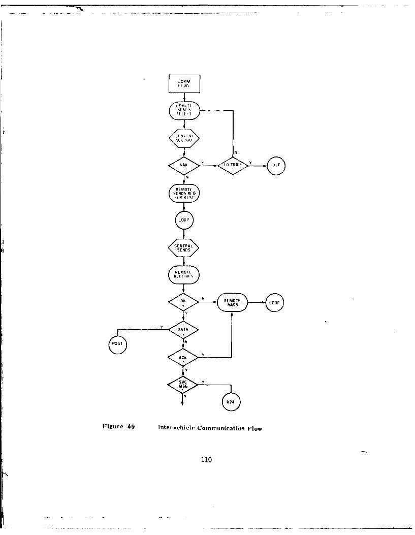
,FI L
A.NI ,As
N
N
RE MOTESENLDS RE:Q
LOOP'
CENTPALSEND S
RLIMU IRI C[ VI
PD DAT
re~ ~ ~~ p 49%t~rhcr omncto ~o
110

NO Y GAF = 0 N OAF - 0REQ
N Y
RLMCTE REMOTENO REQ READY FOR
REMOTE DATA RESPONSI
ACK REQREPORT
NLOOP
DAF 1 LOOP
WA17 y
L TIME
N
R24
PDAT REMOTE N L AD YNAK OR RESP
LOOP
TLRM Y REMOIFNO REQ
NTRO Y VP R C E S'lllj ACK SMOCRECORD EA NNRESP,/
SELECT Y LOOP
NEW RFD DISCONNECTsc
N N
REMOTE y NAK F y PROCESS DISC Y
MAK S FIREORDER
N N
REMOTE AC Y PROCLSS NO N RLMOTELOOP FC FIRE RECI NAK S
DATA COMMAND
N Y
Y RE1610TEDAF z I RR READY NO RL,.'
ACK SM
N
REMOU, 1.00ACK f)ATA
Figor" 49 Int-t-vo-hicic Commimication V10%% (('011CILI&M

This communication scheme was applied in the design of the AGLS-Communication
system. The inherent reliability of the self-testing/self-correcting BISYNC
protocol has proved especially useful when operating in the radio communication
link mode.
Definition of the transceiver electrical characteristics revealed that optimum
digital signal-to-noise ratio could be obtained by using the X-mode radio inter-
face which has the following characteristics:
Transmit Input Z = 600
Transmit Input Level (Full Bev) = Ob (775 my)
Receiver Output Z = 600
Receiver Output Level = up to 6 volts pk
Further analysis revealed that while the transmitter input characteristics were
ideal the receiver output did not go through the squelch circuit and therefore
possessed a continuous noise output. In order to take advantage of the squelch
circuit the receiver output was tapped off the R/T connector on the rear of the
unit. This output was squelched but the level was constant and not effected by
the front panel volume control.
B. Error Analysis
The Automated Gun Laying System was designed to utilize the existing fire control
instruments, and to essentially add a servo actuator and a sensor to each axis
being automated. As a result, the mechanical errors of the existing fire control
instruments will be present in the automated system, in addition to the errors
due to the AGLS components.
Because the geometric complexity of the M109 fire control configuration, the
following error analyses were performed on one axis of control at a time, except
the weapon azimuth and elevation axes. Dynamic errors were not included, since
the weapon is not fired on the move, and all servos will have come to rest before
firing. Errors were calculated for each of the AGLS levels of automation.
112

I1. Automatic Leveling
In the automatic leveling mode, the error sources include the following:
a) Accelerometer null error + 0.75 mil.
b) Accelerometer null error due to scale factor change of 1%, for initial
bias of 10 mils = 0.01 x 10 mils = + 0.1 mil.
c) Servo amplifier input null error of 1.0 millivolt, for an accelero-
meter scale factor of 5.0 millivolts per mil = 1 millivolt + 5 mv/mil =
j + 0.2 mil.
d) Servo loop input required to overcome load friction of 2 lb-ft, with agear ratio of 20:1, a motor constant of 0.1 lb-ft/amp, motor circuitresistance of 10 ohms, amplifier gain of 100,000, and an accelerometer
scale factor of 5.0 millivolts per mil
=2 lb-ft x 1.0 amp 120 10 volts 1/100,000 mil0.1 lb-ft amp 0.005 volts
= 0.02 mil
Maximum untrimmed root sum of squares (RSS) error of AGLS components
= 0.752 + 0.12 + 0.22 + 0.22 = d.783 mil
Assuming the accelerometer and amplifier null error with respect totemperature are linear, and that a maximum short term change would be
0.25 mil, the trimmed RSS error would be
= 0.252 + 0.0332 + 0.0672 + 0.22 = 0.262 mil
Using the above errors, and the errors from the applicable specifica-
tion, the combined leveling errors for the M15 quadrant and the M145mount are shown in Table 2. In combining errors, the instrument error
(excluding backlash) is combined by RSS with the AGLS component RSS
ii 113

TABLE 2
AUTOMATIC LEVELING ERRORS
Maximum Overall Trimmied
Axis Error (RSS) + Overall (RSS) +(Specification) (Section) Backlash (Backlash * 2) _(Backlash-f 2)
M-145 Mount
(MIL-M-46314B) N/R 1.0 mil 1.28 mil 0.76 mil
Pitch or Cant
M-15 Quadrant(MIL-Q-46315C) 0.75 mil 0.30 mil 1.23 mil 0.94 mil
Cant (3.6.2) (3.6.4)
Pitch 0.25 mil 0.30 mil 0.97 mil 0.51 mil
(3.6.1) (3.6.4) ______
114

value, and added to one-half of the backlash. As an example, the
trimmed overall error for the quadrant pitch axis is
= 0.252 + 0.2622 + 1/2 x 0.3 = 0.51 mil
2. Automatic Offset
In the automatic offset mode, the following error sources are considered:
a) Digital/analog converter error = + 4 mv
b) Servo amplifier input null error = + 1 mv
c) Servo loop input to overcome load friction of 2.0 Ib-ft (quadrant), or
load of 1.0 lb-ft at 10:1 gear ratio (pantel) = + 0.1 mv.
d) Total encoder error due to digital round-off plus mechanical error =
+ 1 count x 2.5 mv/count = + 2.5 mv.
Total Error = 42 + 12 + 2.52 = 4.82 mv
Equivalent Error (Untrimmed) = 4.82 mv x I count x 1 m = + 0.2 mil2.5mvI 0 counts -
Assuming that one-half of the digital/analog converter error has been
removed by initial trim, the trimmed error is then
22 + 12 + 0.12 + 2.52 = 3.36 mv = 1.34 counts, or slightly more than
+ 0.1 mil.
3. Automatic Azimuth
a. Reference Unit Acquisition
The reference unit acquisition error is the error that will exist when the AGLS
tracker controls the telescope azimuth axis and causes the telescope to point to
the GACS reference unit. In this mode, the telescope servo will be driving both
115

clockwise and counterclockwise to maintain the tracker on the reference unit.
The telescope backlash will now be inside the servo loop, and the servo will tend
to stay in the middle of the backlash region, whereas the automatic offset mode
or the manual procedures will cause the telescope to be set to one side of the
backlash. This change will always be in the same direction, since the backlash
is removed by approaching the commanded value from a lower number. The backlash
measured on the modified telescope is approximately 3.0 mils.
The IR tracker error consists of two components; an offset which is a repeatable
function of range, and a random noise which increases as the square of the range
from tracker to reference unit. The offset can be trimmed for a given range;
that is, after the howitzer has been emplaced. Further offset adjustment will
not be needed unless the howitzer or the reference unit is moved. The magnitude
of this offset is + 2.0 mils for a range change of + 50 meters from a nominal
range of 100 meters. The random noise will not cause a shift, but causes the
telescope servo to move through the backlash. At ranges of 250 meters and
beyond, the noise increases to a level which prevents tracker lock-on.
The error on initial lock-on, if an extreme change in range has occurred since
the last adjustment, could be
Error = 3.0 mils backlash + 4 mils = -2.5 to + 5.5 mils.2
All of this error can be trimmed out after initial acquisition. Subsequent
acquisitions will result in an error of 1/2 of the backlash, or 1.5 mils to the
right of the reference unit, since the tracker null adjustment is to be performed
with backlash removed.
The remaining error, the input needed by the telescope servo to overcome friction jtorque, is equivalent to 0.02 mil, and as such is negligible in comparison to the
backlash. The remaining tracker error due to noise, range change, and scene
change is estimated to be 0.25 mil, assuming that the tracker has been properly
adjusted at a given range. I
1161I

b. Telescope
The error in the telescope, excluding backlash, is specified as + 1.0 mil. If it
is assumed that 20 percent of the backlash might remain or return after backlash
has been removed, the overall telescope error becomes
(0.2 x 3)2 + 12 = 1.17 mils.
c. Telescope Mount
The telescope mount can be the source of large errors of orientation between the
telescope and the weapon, because of its mechanical arrangement. The mount
specification permits backlash of up to 3.5 mils at maximum quadrant elevation
and zero cant. Preliminary checks on the backlash of the GFE mount indicated
backlash of up to 20 mils. In addition to the backlash, static errors of up to
2.0 mils can exist at high quadrant elevations. For a quadrant elevation of 800
mils, the backlash is specified as 0.75 mil, and the mechanical error is approx-
imately 1.2 mils. Combining these errors results in an RSS error, on an in-spec
mount, of
0.75 + 1.2 = 1.58 mils.2
However, the backlash of the mount had more of an impact on system accuracy than
the specified backlash. The mount backlash, between the tracker (feedback sen-
sor) and weapon (load) caused system instabilities at high weapon elevation.
Since the AGLS was required to operate at all weapon elevations, it became
necessary to implement a drastic reduction in weapon azimuth controller gain to
prevent oscillations. As a result of this gain reduction, other errors became
significant, as described in the following paragraphs.
d. Weapon Azimuth
The error in the weapon azimuth channel is primarily due to the dc gain of the
weapon controller and the error due to friction. Other error sources include
turret backlash, controller offset, and servo valve errors.
117
i

The dc gain of the weapon azimuth controller is 2.00 volts out per volt in. For a
load friction of 10 percent of rated torque, a valve current of 0.03 milliampere
is required, or a valve voltage of 15 millivolts. This would require an input
voltage from the tracker of 7.5 millivolts, or, for a tracker scale factor of 30
millivolts per mil, a tracker angular error of 0.25 mil.
Because of the low dc gain of the azimuth controller, other errors due to the
servo valve must now be considered. These include hysteresis, null bias, and
threshold. Hysteresis is reduced by the application of a high frequency excita-
tion or dither. For the valve being used in the AGLS, the remaining hysteresis
would be approximately 15 millivolts. The valve null error is 100 millivolts,
and the threshold is 25 millivolts.
If the threshold is combined linearly with the load friction effect, the total
system threshold is 15 + 25 = 40 millivolts, requiring a tracker input of 20
millivolts, for an equivalent input angular error of 0.67 mil.
Combining the threshold, hysteresis, and the null errors, the RSS error due to
valve and load friction is equal to
-%402 + 152 + 10i2 2 109 millivolts
or an equivalent input error of 109 + 2 = 54 millivolts, or 1.8 mils angular
error.
If the servo valve is properly trimmed by the weapon azimuth trim control, the
100 millivolt valve error can be reduced to 25 millivolts short term error. The
valve error would then be equal to
-A 402 + 152 + 252 = 49.5 millivolts
or 0.82 mil equivalent error.
The azimuth system gain was reduced to prevent oscillations due to telescope
mount backlash when the weapon was elevated to high quadrant elevations. If the
controller dc gain were to remain at 14.0, the value prior to the gain change,
118
--72 -m mmmm mm

I
the above calculated error attributed to servo valve and load friction effects
would be 109 + 14 volts out per volt = 7.8 millivolts, or 0.26 mil angular error.
e. Combined Azimuth System
With an azimuth controller gain of 2.0 the total system error would be, combining
the following errors
0.25 mil tracker offset
1.17 mil telescope
1.58 mil mount
0.82 mil azimuth servo
The resulting azimuth RSS error would be
0.252 + 1.172 + 1.582 + 0.822 = 2.14 mils.
This error prediction is based on the assumption that the tracker and weapon
azimuth servo have been properly trimmed.
If the AGLS components are not considered, the combined error of the M1O9A1
components would be
1.17 mil telescope error
1.58 mil mount error
or a combined error of
1.172 + 1.582 = 1.97 mils.
Thus, it can be seen that the added AGLS components in a properly adjusted system
add less than 0.2 mil azimuth error, when RSS errors are compared.
1[ 119
I

4. Automatic Elevation
In the automatic elevation mode, the quadrant is driven by the digital controller
to the commanded quadrant elevation, and the level error, as sensed by the
quadrant pitch accelerometer, is used to drive the weapon, thus reducing the
accelerometer level error to zero. The error sources to be considered then
consist of:
M-15 Quadrant Mechanical Error
Quadrant Automatic Offset Servo Error
Accelerometer Offset Error
Weapon Elevation Controller Error
The impact of each of these error sources on the total elevation error is
described in the following sections.
a. Quadrant Mechanical Error
The specified error for the quadrant elevation reading is 0.5 mil. Since the
AGLS encoder is coupled to the elevation knob, and the accelerometer is coupled
to the level vial, the error between elevation knob and level vial will also be
present in automatic elevation. It will be assumed that all of the 0.5 mil error
is between elevation knob and the level vial.
b. Quadrant Automatic Offset Error
As discussed previously, the error of the automatic offset mode is 0.13 mil.
Since this mode determines actual quadrant setting the same error will be one of
the error components in the automatic elevation mode.
c. Accelerometer Offset Error
The trimmed accelerometer output voltage is used to control the elevation drive.
Thus, if the quadrant pitch servo was previously trimmed, the residual accelero-
meter error will be reduced to approximately 0.25 mil short term error.
120

d. Weapon Elevation Servo
The elevation servo error consists of the error needed to overcome imperfect
weapon equilibration, load friction, and servo valve errors. The dc gain of the
elevation controller is 225 volts out per volt in at the minimum gain setting.
The adjusted gain is estimated as 300 volts per volt.
It is estimated that the equilibration mismatch is + 10% of supply pressure for
different weapon elevations. The load friction is estimated as an additional +
10% of supply pressure. Since the elevation servo valve, a pressure control
valve, can develop full supply pressure with 3.0 volts applied, the valve voltage
needed to overcome load friction and unbalance is combined by RSS to be
(0.1 x 3)2 + (0.1 x 3)2 = 0.42 volts.
The valve hysteresis, reduced by dither, is 1.0 percent of full scale. The valve
threshold is 3.3 percent of full scale, and the null bias is 5.0 percent of full
scale. The combined RSS valve error then becomes
-V (0.01 x 3)2 + (0.033 x 3)2 + (0.05 x 3)2 . 0.18 volt
and the combined load plus valve error is
-N0.422 + 0.182 = 0.46 volt.
The equivalent input required to obtain 0.46 volts out is 0.46 + 300 = 1.5
millivolts. Since the accelerometer scale factor is 5 millivolts per mil, the
equivalent angular error due to valve and load errors is 1.5 + 5 = 0.3 mil.
e. The dc input offset of the elevation controller module is 1 millivolt,
equivalent to 0.2 mil angular error.
f. Combined Error
The RSS combined elevation error consists of
121
LI

0.5 mil quadrant error
0.13 mil automatic offset error
0.25 mil trimmed accelerometer null error
0.30 mil elevation servo error
0.20 mil controller offset
and is calculated to be
+ 0.132 + 0.252 + 0.302 + 0.22 = 0.68 nil.
The elevation error without AGLS would be due to quadrant error alone, and would
be 0.5 mil assuming no operator errors. Thus, errors due to the automatic
elevation components would increase the RSS error by 0.18 mil, if the components
are trimmed using the given procedures.
122

VI. SYSTEM DEVELOPMENT AND FABRICATION
Following the three month design study, development of the AGLS components was
initiated. Initial emphasis was placed on the long lead time components, pri-
marily the instrument servo actuators and the infrared tracker, primarily be-
cause these components were recognized as the major technical problem areas, but
also because the other components (controller amplifiers, power supply and con-
trols and displays) would depend on the characteristics of these components. The
weapon drive system was assembled almost entirely from M16A1 Add-On Stabiliza-
tion System components. The development plan for all of the other AGLS com-
ponents was to generate layout drawings in sufficient detail to verify their
mechanical suitability, prepare drawings of the subassemblies which would permit
fabrication by design technicians, and mark up the drawings during fabrication as
the need for design changes became evident. The development of the major AGLS
components is described in more detail in the following paragraphs.
1. Fire Control Instrument Servos
Early in the development phase, the gearing, drive motors, and other servo
components required to provide automatic operation were designed into the M15
quadrant, M145 mount and M117 telescope. Space available for these components
had been estimated from the available government drawings, and appeared to be
adequate at the time the design review was conducted.
Later, when the M109 was delivered to the contractor, wooden mock-ups of the
servos were fabricated and installed on the fire control instruments. It was
then found that the added drive components caused interference when the vehicle
was canted beyond 5 degrees. Since it was decided that full cant performance
capability must be retained, additional effort was exerted to redesign the servo
housings to provide full 10 degree cant capability. This redesign activity
consisted primarily of installing the wooden mock-ups of the servo components,
displacing the fire control instruments to their extreme positions, removing the
interfering material, and rearranging the internal mechanical components to fit
123

within the available space. As a part of this redesign effort, a different motor
and tachometer were selected. The new motor has less torque at a higher speed,
so 20 to 1 gear ratios were needed to meet the torque requirements of the two
mount axes and the two quadrant axes. The calculated speeds for maximum load
friction for each servo are shown in Table I.
Inspection of the worm gears in the quadrant and mount revealed that the existing
mechanical stop, consisting of a screw in the sector gear, was not adequate for
the higher torque available from the servo motor. Limit switches were then
installed, to interrupt the motor current when the servo approached the mechan-
ical limit. Each switch is bypassed with a diode which permits reverse motor
current to automatically provide drive away from the limit. In addition, resil-
ient stops were installed beyond the limit switch settings to cushion the impact
in the event of a hard-over failure. The instrument servo drives, modified as
described, were then capable of operating to within 0.5 degree of + 10 degree
vehicle cant and pitch.
Following completion of the fabrication of modified servo units, open loop fre-
quency response data was taken for each of the fire instrument servo units as
shown in Figures 50 through 54. In each of these tests, the tachometer feedback
loop was closed, a sinusoidal forcing function applied and the position sensor
(accelerometer or IR tracker) output was measured in magnitude, and phase. After
developing the controllers for each axis, the closed loop frequency response data
representing final servo performance were taken and are plotted in Figures 55
through 59.
2. IR Tracker
The proposed method of detecting and locking-on to the GACS reference unit was to
use two solid state video cameras, each utilizing a charge-coupled device (CCD)
array. However, about five months into the program concern was raised over the
projected size of the optical elements needed by these two cameras. Since the
camera could not resolve readily to any smaller image distance than that of one
sensor element, it would have been necessary to use a large focal length (10
inch) lens to sense 0.5 mil.
124

10 0 2<0 -a an c
...I . .1. .1
I-In
I0 F
- CLTC I
F L
.1u 0
0 0t
-- U US
Inr tLL0.
W1 000
r. -p-J
125- 0

0nIt 00 0CD0 0
____ _____ fl 1Q) ' ~ t '--'-
6 _______ _______
CL
x +.
1~~~~L 4-)__ _ ___ ___ _0
'30
Li..
2 ___ ___ ___
C- l (cqp) apnj&u56EW
126

0 03 0 el
0
'~~~~S r0~zm-
I - 0
LC
4 41 ----r
12

0 0 0 -
0
9- 7: --
4-.~ - ___I_______
___ ___
I __
0
0
-fr-r
____CU
j4 M
9 4
S0
if:7 _ __
.J~+ n
m (qp apri~l!u6 pW
128

a' CD Cfl CD,
10 4-
-L - 4 ___
9 5. V -4 CD
.4 . .2 . CL
AA I
r-. 0
I..-
f - V C LV
H IA.
t_ _ T- 7 .--
19

-D CD C.
iA I . 5
0 . . . .
CC
04
.. 4J
130)

.- C) CI
ClC.i,
I
. w.
4- j
. o.
C)1 -t 0
I I U
131 ITt-a

C) CD '4~5'
10 ci -l -l
fn
I .. S
ti CL4.Urit iii-
3 .- ... . . _ __
u
t 1-
J.0
3
-=77._ _ _ _4
6. . .. ....
5 ~*.44j*~~' ,- .40
____ -D
9 _-~-
7 Sw
T- 0 c)
LA.
j~ t z~7r. f2_7.. %0- . 0
j~OqP) apn~u6P.j
132

C)C C)
7 CL
CL
a,0L
jC~~~~4'CD 4----- . .a
4.. -- CDI.
j S2
(qp) ari, bpwa,
133
low

-~~~~ s (1 'sP qd I
Wuj4 3
U..
I= LI-
C) C
1-i4
I 0L.
* jDC) I _D__
134)

One solution considered was to integrate the tracker into the pantel optical
system, thus utilizing the pantel magnification to reduce the added magnifica-
tion needed by the AGLS tracker. However, it was apparent that space was limited
in the vicinity of the pantel eyepiece, thus potentially creating packaging
problems. In addition, the optical accuracy with respect to the lower housing
would be degraded.
Analysis of the XENON sterradian lamp energy, based on a Frankford Arsenal
measurement of 2500 watts per sterradan, suggested that a CCD array might not be
able to detect the XENON lamp in the GACS reference unit. This concern was later
determined to be a major problem, when the GACS reference unit was delivered to
Honeywell in January, 1977. The reference unit was first set up in a 50 meterindoor ballistic range, and viewed with a commercially available GE camera with a
CCD array. The camera could detect the XENON lamp, but the camera lens was
opened to a low f-number. The camera output, as read on a television monitor,
also exhibited a vertical row of spots rather than a single image. This ghosting
would not be acceptable for the AGLS application.
The reference unit was then taken outdoors for further imaging tests. The camera
could not detect the XENON flashes, either with a video monitor or with tracking
electronics. The problem was more severe outdoors, because the bright scene
saturated the CCD sensor when the lens was opened to the number needed for the
indoor tests. At higher f-numbers which took the sensor out of saturation, the
tracker would not be able to detect the XENON lamp under any ambient light
conditions.
The problem is caused because, although the light output of the XENON lamp is
high, the time duration is short (1 to 2 microseconds) and the repetition rate is
low (160 pulses per second). This results in a low level of average energy.
Since each element of the CCD array integrates all light that falls on it during
one scan period, the pulse energy is a small fraction of the total energy seen bythe array element. Two viable solutions to this problem were considered:
1. Place an electronic (PLZT) shutter, synchronized to the XENON flash,
in the optical path to reduce the amount of ambient light while
admitting all of the XENON light.
j135

2. Utilize a photodiode sensor which would respond in real time to the
high energy pulses, thus producing a high output pulse over a low
background ambient signal.
Electronic Shutter
The application of a PLZT shutter to the CCD array was evaluated by several
technically qualified personnel. It was determined that although the PLZT
shutter would meet the GACS interface requirements (20 to 200 microsecond trans-
mission time at a 160 Hertz rate), there were no off-the-shelf drivers in exis-
tence to control the shutter. Thus, in order to evaluate the PLZT shutter in
conjunction with a solid state camera, it would be necessary to either build a
PLZT shutter specifically for this application or design and build a special
driver amplifier.
The PLZT shutter has a capacitance of 0.01 to 0.05 microfarad and must be driven
by a 600 volt pulse. For a 20 microsecond wide pulse, the peak current to the
PLZT would be from 1.0 to 5.0 amps, assuming a current with a half sine wave time
function. The combination of high current and high voltage could cause Electro-
magnetic Interference (EMI) compatibility problems with the CCD array, since the
CCD depends on the generation and transfer of small amounts of charges.
Segmented Photodiode Detector
A segmented photodiode detector system, designed by Honeywell for aircraft fire
control systems, was tested to determine its ability to detect the GACS reference
unit XENON lamp. This detector was able to readily detect the lamp to ranges
beyond 500 meters even in bright sunlight. This test proved that a photodiode
sensor detecting in real time was the best solution.
A problem with the segmented detector is that present manufacturing technology
cannot provide separation between the elements of less than 0.001 inch (25
micrometers). If a 50 millimeter focal length lens were used, this would result
in an angular dead space of 0.5 mil in which the lamp, as a point source, could
not be detected.
136

To circumvent the problem of a finite dead space, a sensor was investigated which
provides proportional information on the position of a light spot. The sensor is
a lateral-effect photodiode with two output leads. The output current from the
leads can be combined by the sum-and-difference amplifier to obtain a signal
proportional to the distance of the light spot from the center of the photodiode.
A sample of this device was ordered and evaluated for use as a detector.
The spot continuous diode was found to be ideally suited to the GACS tracking
problem, for the following reasons.
o It responds to the peak of the XENON flash, thus providing a compara-
tively large signal to noise ratio.
o The diode responds linearly to light level, so that steady state back-
ground illumination can be readily removed from the total sensor
signal thus enabling detection of low energy pulses.
o The diode provides a continuous measure of image position, without the
descrete steps and dead spaces of a CCD or segmented detector.
o A short focal length simple optical system can be used.
o Only one detector and lens system is needed.
o The sensor is commercially available off-the-shelf at a reasonable
cost.
The spot continuous diode was further tested, and electronic circuits were
developed to best utilize the signal from the diode. A complete description of
the tracker is included in Section III and IV of this report.
3. IR Tracker Noise
A fundamental problem in tracking the XENON lamp is that at far ranges the energy
level of the light pulses decreases as an inverse function of the square of the
range. The XENON lamp does have enough energy to permit detection. However, the
j137

AGLS tracker is intended to resolve aisplacement of the XENON lamp, down to 0.25
mil, and has a field of view of + 100 mils. Thus, the tracker must be able to
resolve a signal corresponding to 0.25 percent of the total energy applied to the
sensor.
The tracker was tested with the GACS reference unit at an indoor range of 17
meters. To simulate longer ranges, aperatures were fabricated to reduce the
optical entrance area. These tests demonstrated that at 70 meters distance from
tracker to reference unit, the tracker output noise is equivalent to a displace-
ment of 0.5 mil peak to peak, increasing to 2.0 mils at 140 meters and 8.0 mils at
280 meters.
The observed noise appeared to be essentially uniform with respect to frequency,
and could be reduced by filtering. However, the servo system driven by the
tracker cannot tolerate additional filtering since excess phase shift will
result.
The tracker noise, therefore, will not permit reference unit lock-on at extended
ranges. This was demonstrated in the AGLS acceptance tests, during which lock-on
could not be achieved at ranges greater than 200 meters. To extend the lock-on
range would require either more power from the XENON lamp or a larger entrance
pupil area on the tracker. Since the reference unit is provided as GFE, it
cannot be modified. In addition, it might be undesirable to increase the light,
output from a countermeasures viewpoint. Increasing the tracker pupil area would
add to the tracker size and weight, further compounding the problem of the
mechanical loading on the pantel and mount.
This deficiency was avoided during the acceptance tests and the Ft. Sill tests by
keeping the reference unit within 50 to 100 meters of the howitzer. At these
ranges, no problems were encountered in either acquiring or maintaining lock on
the reference unit.
The tracker was installed on the Ml17 telescope, and data taken on output voltage
as a function of telescope deflection when viewing the GACS reference unit. The
results are shown in Figures 60 and 61. The two curves on each figure represent
clockwise and counterclockwise rotation of the telescope. The difference
138

U C
-- Ce
4.J E
ca. 0
:3 t-
.. efu cI
0- ' 3
4--
0 i
FEE>n,
-4
- -~ 4J(A0 .
EnD.'M
In E=
139-

-6-
KE E
- CJ
-4 C
0
.-- - - -4-- .- ---. - - - - - ---4I
I>Lo)
L 42-SE_
I o - ) ____ __m
It,-
co M
EE E E
or u~uco- to-.. O S-
4J 0) 10- _ C 4LOd) to_ .-
41* -
06
f3 C3It
00 140

between the two curves is due to telescope backlash. The increasing slope of the
curves as the telescope moves away from center is believed to be caused byreflections placing multiple images in the tracker field of view.
4. Telescope Backlash
When the IR tracker was mounted on the M117 panoramic telescope, the backlash
measured either optically or by the tracker was 5 to 6 mils compared to 1.0 mil
required in the telescope specification. The AGLS controller is configured to
always drive the telescope from a lower number to the desired final number and
thus stay on one side of the backlash, using the same procedure as is now used by
the gunner. However, this procedure cannot be expected to remove all backlash,
and some small amount will remain. This residual backlash Is probably propor-tional to the total backlash, so it is desirable to reduce this backlash toimprove the overall accuracy of the telescope in the manual and automatic offset
modes.
A second reason for reducing the backlash is that, during reference unit lock-on,
the tracker is continually driving the telescope and reversing directions as the
telescope servo approaches a null. The backlash will then cause the servo motor
to continually hunt through the backlash region, and cause a servo instability.
In addition, the telescope/tracker servo will tend to null in the middle of the
backlash, but the telescope, when driven by the gunner or under command of the
digital controller, will null at one side of the backlash. Thus, the telescope
will appear to be in error by one-half of the backlash when the tracker is used to
control the telescope.
The backlash was reduced to 2 to 3 mils by Ft. Sill personnel during the system
acceptance tests. This was accomplished by turning-in the worm shaft spring
adjustment which is external to the telescope. The spring did not require any
additional adjustments through the acceptance tests or the Ft. Sill dry firing
test sequences. However, during live firing the backlash increased. Again, it
could be reduced by turning-in the screw. Since the actual screw position before
firing was not marked, it is not known whether the backlash increase was due to
the screw moving or If changes occurred internal to the telescope during gun
jI firing.
141.!

The telescope was later disassembled and inspected by Ft. Sill field maintenance
personnel and a contractor's representative. No sign of mechanical wear could be
found. The servo drive was then removed from the telescope and the back.lash was
rechecked. The telescope backlash was less than 1 mil, as required by the pantel
specification.
It appears that the springs which axially and radially load the pantel worm shaft
are not adequate to hold the shaft against the motor friction and the motor
torque. It would be desirable to incorporate stronger springs to keep the worm
shaft in place. However, the increased loading could possibly increase the
friction on the pantel.
A design study is needed to review this problem area and to determine what
changes can be implemented.
5. Control and Display System Configuration Definition
During the Design Study phase, the need was recognized for data displays
distributed among the several gun crew members. Specifically, the chief of
section requires full display of all data since he is responsible for proper
laying of the weapon. In addition, the gunner must have available at his station
a display of all azimuth data, and the assistant gunner requires the elevation
data.
The Design Study also pointed to the need to easily modify system configuration,
and thus change certain fire control functions from manual to automatic. Since a
certain configuration might require proper function of other subsystems, it
became apparent that a high level of logic would be required. To provide the
additional data displays for all crew members, the contract was modified to
require three separate display panels as well as a separate digital controller
unit. The three display panels would all receive their display data by means of
a data bus, thereby reducing the number of display wires between units from an Jestimated 480 wires down to less than 60 total conductors. ITo satisfy the need for an easily modified system configuration, the contractor
selected a microprocessor based digital control subsystem. Such a system can 3142 3

easily be altered by external configuration selector switches, and can be inter-
faced with the other AGLS subsystems to provide a high degree of operator safety.
The digital system is compatible with the data bus selected to service the data
display panels. Another advantage of the microprocessor is that it will permit
changes in system operation to be implemented by a simple software modificationwith no changes in components or wires. Since Honeywell has a complete micro-
processor development facility, including semiconductor memory programming
equipment, system operating characteristics can be modified by programming a new
memory array in a matter of hours.
The block diagrams and descriptions of the digital controller unit are given in
Section II1. Detailed schematics of the controller unit circuits are shown in
Figures 62 through 67.
AGLS Software Development
The AGLS Controls and Display software has been designed to:
o Sequence control operations as a function of the mode selected.
o Acquire fire order data from the GACS gun unit.
o Monitor leveling servos and GACS reference unit detector.
o Compute pointing errors as the difference between commanded and mea-
sured angular data.
o Display commanded, measured and error quantities as well as level and
reference unit detector status.
o Provide overall system performance checks to insure safe operation.
o Interface with chief of section controls to enable interactive opera-
tion.
143

F7Lj~ ~
cr 'TST 0vi-p -
144 1a

II
4
t ) 0
0.0
T'N
411
CL)
(.W3 - -- - gA w - 6 L)t
LL.10
-~ .I I145

4.4
C.4J
44-
.1.1
%A K%..
4.1
C-44
1461

I
.- C
N~ 00~ 4
I, "
+<- " - r- - : i-. V-- - j ill"
>*C.. .! . . ,-.- - - 1. +p.i
.12£> *.- I J-
147
>4i 0----L , a
£)i (
I 147

-A-
7,. -TTT--
cc 0.JI
148 .

- Al 7 A
;I Z3
I-I 31 7 vI
AHDO 33 P9'7 19
I o)S A' 3,r 1/
837 -~. 39l ~Ak 37,31
4 C 2. P,371?S4' csj CS cool IFg 41
23 L3
'C 1v 9414E:91~ ~ 41S
46A
&0r~£Pt- + p P7
A~s ~ ~ 3 31
k~ur 67. Paale Intefa
A14- V,4 149

The overall structure of the software employs a main program which sequentially
executes a variety of subroutines. This main program and supporting subroutines
are written in Motorola Assembly Language (Version 1.00) which is documented in
Motorola M6800 Microprocessor Programming Manual (M68 PRM(D).
The main program is supported by an interrupt driven background package which
performs the functions of:
o Providing five double precision (16 bit) programmable timers with 1
millisecond resolution.
o Servicing the Digital to Analog converters for azimuth and elevation
each 20 milliseconds.
o Testing for the presence (or absence) of the XENON lamp signal each 20
milliseconds.
- If the XENON lamp signal is present, and has been present for 25
consecutive tests (500 msec) the XENON recognition flag (XRECF) is
set.
- If the XENON lamp signal is absent, and has been absent for 1
second or more the XENON recognition flag is cleared.
o Determining whether the weapon switch is being toggled, each 20 milli-
seconds, and setting the weapon flag (WPNF) if the switch is enabled.
o Updating the displays and status indicators each 200 milliseconds.
Display update is inhibited if new GACS data are being acquired or if a
computation is in progress.
The background package is also used to service a program activity monitor which
allows examination of the data and flag buffer contents through the use of a CRT
on serial port $3002.
150

IThe main program is structured to run continuously through either the first,
second or third loops (Appendix B) depending upon the position of the servo and
weapon switches.
The first loop (idle loop) is the only loop active when the servo switch is off.
The routines in this loop read commanded (GACS) data, encoder trim, encoder data
and servo system status. The difference computation is performed and results aredisplayed. Manual adjustment of pantel mount and quadrant leveling will be
monitored and the appropriate indicators will be illuminated when the values arewithin established bounds. The system must be operating in this mode to latch in
new configuration data or to read information from the GACS system.
The second loop is active anytime the servo switch is on. This loop services the
pantel search and auto offset mode of operation and performs the preliminary
tests for the automatic modes. Auto-offset mode selection, in either azimuth or
elevation, drives the appropriate fire control instrument to the angle commanded
via the GACS link. In the azimuth axis a special control algorithm is employed
to ensure that the pantel is always driven to the specified angle from the left
to right (as observed from the eye piece by an operator). Azimuth search isinitiated in the auto-azimuth mode by toggling the switch on the chief-of-section
control panel. This operation mode can only be disabled by tracker acquisition
of the GACS reference unit or by disabling the servo switch.
The third loop is enabled by actuation of the weapon switch. Before the switch
signal will be recognized, the first loop conditions of XENON signal stable and
quadrant offset null must be satisfied. Once recognized further testing of the
second loop in inhibited. Third loop processing proceeds (if the auto mode has
been selected) three continuous checks of the XENON stable signal, by commandingthe appropriate weapon servos to position the turret and tube. In the elevation
axis a one second delay is employed to ensure that quadrant accelerometer tangen-
tial influences have been minimized prior to initiation of tube movement. Ifload position was selected, and falls within prescribed limits, the tube is
driven to the elevation selected by the configuration switches. When QE is
selected (load deselected) the servo has to be disabled in order to latch in the
commanded elevation angle. System stabilization, as determined by tracker andquadrant staying within specified null limits for a timeout period, is signalled
I151

by flashing of the numerical displays. When this happens, the program goes to
idle mode (Loop #1) and the weapon flag is inhibited. To reset the system, the
servo switch must be toggled.
A detailed flow diagram of the main program is presented in Appendix C and the
annotated source listing of the entire program is included as Appendix 0.
6. Vehicle Communication Processor (VECOM)
The vehicle-located functions of the add on scope of work consist of the Vehicle
Communications Processor, which provides two-way data communications with the
FDC, and the Reference Unit Processor, which determines the Reference Angle for
the GACS subsystem. To minimize the component placement problem, it was decided
to house these two processors in a single assembly, mounted at the Chief of
Section work station; as shown functionally in Figure 68. Interfaces to the
AGLS, AN/VRC-46 Radio, DR-810 velocimeter, electronic fuze setter, and propel-
lant temperature measurement system, were implemented by a start interconnect
scheme as shown in the cabling diagram 28116114, of Figure 69.
Both the VECOM and RUP were implemented using the Honeywell H1O microprocessor.
This MPU and its supporting board set is shown schematically in Appendix A.
Throughout the AGLS-COMM add-on system the respective elements of the H10 (MPU,
Memory, PIA, etc.) are interchangeable, differing only in the instruction sets
stored in the socket-mounted EPROMS. Two unique circuit cards were fabricated
for VECOM; the reference unit phase locked loop and the processor DC power
supply.
The pulses from the GACS IR receiver are preconditioned with the phase locked
loop, which establishes time windows to accept the XENON pulse (see Figure 70).
It was found that the S pulse was approximately 2.5 milliseconds before the next
X pulse. The phase locked loop is synchronized with the X pulses, and a time
window equal to + 10% of the pulse period is opened to accept pulses for trans-
mission to the digital processor. Any pulse occurring in this window is assumed
to be an X (and not S) pulse. A second window is opened from 3.2 to 4.5
milliseconds after the X pulse to accept an S pulse.
152

CHIEF OF SECTION DIGITAL CONTROL ELECTRONICS
PIA -,FENCODER!AZ AND EPIA 2 AND
=TRIM A/(PIA 6
GUNRS IPA PORMRADMLACDISPLAY~~PI PI IEOR CE
MU I 0/AI RORMBELAYG
0A PEA4 TIE4I
ISLAEDiSLAEDISLAEA/ AND 0/A RELAY
MUX 2 CHANNEL, DRIVER
SERVO AMP AZ ESETRCVTROMONITORS SEVO RELAYSFIGURE 680LREAY
153

TESTSWITCHES
NICS
SWITCHREGISTER ENCODERS: AZ ENCODER
PIA 20N
MOTOROLAM6800
PROCESSOTRM-A ZA/
r -RAMIR ANDOM
ORAM ACCESS
R :OM) MEMORY
RIAL ROGRAMALPORT TIMERPII
D., RELAYD/A DRIVER
COVETE PIA 4
ISOLATEDISOILATE13ISOATE RELAY
2 CHANNEL DRIVER
ASERVOS rRELAYS
(CONTINUED ON FIGURE 68b)
153

LIE*---- I UE PROP.cm.SETTER TEMP.
RADIO
__________________________________ PIA I
PROCESSOR MODULE PARALL-EL INTERFAC
CROPOCESOR A ASSDATABUFFERSS
ok I0
1441 SPARALLEL PARALL
y TECE 1ITERj
TE 2
SS
IPOWER SPLY MO
__________MACE_ RGLLATORSFL
FIGURE 68b
154

FUZE PROP.
SETTER TEMP. VELOCIMETER
CC082)
~I REFERENCEUNIT
r PROCESSOR
PtA IPIA 3
PARALLEL INTERFACE MOOLLE
AAARSR
141s PARALLEL PARALLEL PARALLEL PARALLEL
Y 1 TEFFACE INTERFACE INTERFACE INTERFACE
BuS
REGUj~LATORS WEERR 26 o
154

t ;z
v w08.I .
0i L
V, ,<cr S .4
(_)1*UOJ2tn-
ZIm155

LLi-AJ
CD2! Cc LJ L io) .-. (iC- LiiJi
LL.1-I- L.iLi cc
C-) V)CCw L.)Lii LL LJ (D m.iI LL LA LL-LLJ CX L& Jf -i
cc a
) 0- 04C
I o 0u
CLi
Lii
LLJLicLAi
IL/L.
cn LAJJL
C)-J
sV4 LA-
-JL
o
V)I
156
The LASER pulse is passed directly to the processor, since it is not synchronous
with the XENON channel.
The time gates established by the phase locked loop eliminate approximately 80%
of any spurious pulses which might be detected. Further filtering is performed
in the processor software.
The processor DC power supply was designed to convert raw vehicle power to the
variety of voltages required to support the microprocessor system. In addition
voltage outputs were provided to power analog supporting subsystems such as the
GACS detector.
Operator interface to VECOM was via the controls and displays subsystem. Thisdesign used a front panel layout as shown in Figure 71. The operation of VECOM
via this panel is described below:
On system power up (using the master power switch on AGLS) VECOM is in the
STANDBY mode as indicated by the pilot light. The ELEVATION, DEFLECTION, FUZE
and CHARGE displays will indicate 0 since no gun orders have been transmitted tothe vehicle. If the GACS reference unit has been acquired and good data are
being received the GACS lamp will be lit and the X and L monitors will be flashing
at an approximate rate of 80/sec and 1/2 sec respectively. The reference angle
can be read by switching the MODE switch to the REF position.
The operator initiates a connect to the FDC by moving the momentary COMM/STBY
switch to the COMM position. A select is sent by VECOM, acknowledged by FOCOM
and a turn around code sent by VECOM. At this point VECO is in the slave mode
(listening) while FOCOM is in the master mode. The COMM lamp will be lit when the
system is connected and GACS/RUP operation continues as before. During the
exchange of data the monitors 0-5 will flash on and off; the meaning of each is:
Monitor 0 - VECOM is transmitting
Monitor 1 - VECOM is receiving
Monitor 2 - VECOM is processing the message
Monitor 3 - Data Carrier Detect
Monitor 4 - AGLS Comm Link Busy
157L
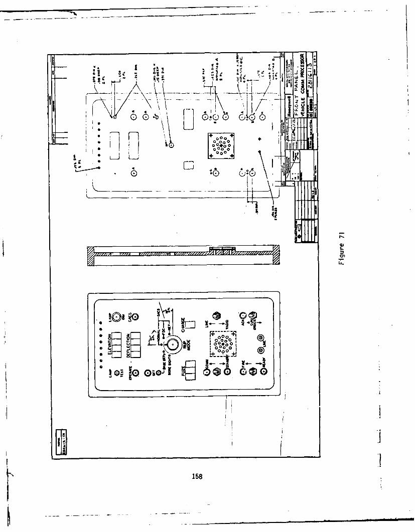
r
7T
--o -] ... .. . . - ' ,, o~
-T1 -7--
I U
L L_
lia4N
2 --- -
- 001
5 I'II yl/llllIl Al0. - .l00
or-
0000
19.~
0 0 C) -30 . 2
158 0

Monitor 5 = Message NAK
When a gun order is sent from the FDC to VECOM the GUN ORDER ACK lamp is
illuminated and the beeper sounds. The respective elevation, deflection, fuze
and charge values appear in the displays and are relayed to AGLS. The operator
acknowledges receipt of the gun order by moving the momentary switch in either
direction. This acknowledgement sends the received gun order back to the FDC for
validation and generates an automatic ready request. The ready request lights
the READY monitor in VECOM and initiates an automatic sequence of updating thereference angle to AGLS. When the weapon has been laid the READY is acknowledged
by moving the momentary switch toward the ready lamp. This action terminates the
automatic reference angle update to AGLS and sends the data report (consisting of
all AGLS status and numerical data) back to the FDC. When the FDC sends the fire
command the FIRE lamp illuminates and the horn sounds. As soon as the shot is
fired it is signalled to the FOC by moving the momentary switch toward the FIRE
lamp. This action sends data report to the FDC. Upon receipt and acknowledge-
ment of this data report the FOC requests an additional report. This latter
report contains the measured projectile velocity from the MVR. Messages need not
be received in the aforementioned sequence. Gun orders can be sent sequentially
to update other gun orders. Check fires (denoted by a flashing display of 9'sand acknowledged by the READY switch) can be issued at any time to halt amission.
Operation of the system, insofar as communications are concerned, is identical In
either the GACS or Base Deflection (BD) modes. In the latter mode, base deflec-
tion initialization is required. This is accomplished by selecting Base Deflec-
tion Mode, adjusting the AGLS pantel to acquire the distant aiming point (DAP)
and depressing the BD SET button. When the BD setting is locked into the AGLSprocessor the SET lamp will be lit. One can either operate in this mode or switch
back to GACS mode; the BO value remains locked into the computer unless it is
powered down. In operation, in BD mode, the preset reading obtained from the
pantel and stored during the set operation, is subtracted from all subsequent
absolute encoder readings such that -if the pantel is directed at the DAP the
ACTUAL azimuth reading would be 3200.0. In the semi-automatic mode of operation
(automatic azimuth offset) azimuth gun orders from the FOC are directed to the
pantel to drive it to the specified angle. The cab must then be rotated by the
159

gunner through the power handle to acquire the DAP sight picture; the weapon is
then laid in azimuth.
The front panel VECOM displays and controls were designed to minimize Chief of
Section (COS) workload. In the fully automatic mode of operation only one
control is required from the AGLS COS panel and that is the weapon lay enable
(WPN).
The software designed for VECOM is shown in flow form in Figure 72 and the
associated assembly level source code is contained in Appendix B.
The reference unit processor, being sufficiently different from any other proc-
essor designed until now, was programmed using the methods of top down software
designs. The circuit elements, shown in the block diagram, consist of the GACS
IR Receiver, a phase-locked loop, and a standard microprocessor with input/out-
put, random access memory (RAM), program memory and a central processing unit
(CPU).
The inputs to the RUP are three pulses:
X = A XENON pulse occurring every 40 mils of LASER rotation.
S = A pulse occurring once for every 160 valid X pulses, spaced between two
X pulses.
L = A pulse occurring once for every S pulse, at any timing including
coincidence with an S pulse or an X pulse. IThe outputs of the RUP are to be:
o The reference angle from 0 to 6399 in binary coded decimal, and
o A status flag showing that the currently computed reference angle is Ivalid.
I160

FUNCTIONAL FLOW AGtsAGLS VEHICLE FirCLECOMM PROCESSOR I .om I
(PARTIAL) P9oeffU4.
FIGURE 72a A#T
/,-MNiTrIAL rI e% '
FAp RAIMAND S~AG
- srTRY cooNT'
= 10r#4rrrd Lrze
N E ,Pe tel'I
t-0 PE
rowrTMALTLZ
IIM
D ELA Y
A6r LS
FodA LF
INTE PvfUD1
vc1
J- #IALI %C
vc (CONTINUED ON FIGURE 72b)
161
..... .. .

FUNCTIONAL FLOWo?AGLS VEHICLErCOMM PROCESSOR
(PARTIAL)
FIGURE 72b
(CORIOE VS.$ FIUR 7
N 162

FUNCTIONAL FLOWAGLS VEHICLECOMM PROCESSOR
(PARTIAL) v
FIGURE 72:,irS
ALE.S VS
?v~
j ~~~r.*~ (CNIUEvNFGUE7d
1*6 163 Te

FUNCTIONAL FLOWAGLS VEHICLECOWf PROCESSOR
(PARTIAL) i
kFIGURE
72d
o D P 4Li
164

FUNCTIONAL FLOW vAGLS VEHICLECON PROCESSOR(PARTIAL)
FIGURE 72e
Iq
U %1 5r'PATAro AGLS
S o -i eL"
vel~#vpy
f .Tjt~w rA&T. A I Y
A(,TAY ,?
I40
SfLG ovs
I ,F, AP
WIT (CONTINUED ON FIGURE 72f)
I 165

FUNCTIONAL FLOW VCI1
AGLS VEHICLECOMM PROCESSOR
(PARTIAL) CLp A
FIGURE 72f FLACY
Li
ZDLA FLAC S LITIYE'S
CvET votjt
L33
C S (CNINE OHFIUE 2g
s 1e66Ot" FLA&ZI

FUNCTIONAL FLOWAGLS VEHICLECOMM PROCESSOR(PARTIAL)
FIGURE 72gFL& 2
S- ...-c--

FUNCTIONAL FLOW V9141CLIKAGLS VEHICLE Pt soiCOMM PROCESSOR ~owmik w(PARTIAL) letrAAthp
FIGURE 72h
p Oka 6 A AMAmb SiRAG F
TtPI PR
PFLAYF o R
AG L S
LOA 1)
ff A'A 8 LIE
6rArS Ad~
S7WAEj o~
APLA4ZN
(CONTINUED ON FIGURE 721)
168

I FUNCTIONAL FLOWAGTL S VEHICLE
CO1l PROCESSOR ,'"(PARTIAL) , L S rW IV*FIGURE 72(OTNEONFGR7
169
re 59 SRVVSi r0ftowt
PotF Ia___.Jo
I (CONTINUED ON FIGURE 72j)
~169

FUNCTIONAL FLOWAGLS VEHICLECOMM PROCESSOR yrs(PARTIAL) A GLS
FIGURE 72i
ONO
I'IS w #i Tll0
IMuS It ra'lo
$IT
~1
J (CONTINUED ON FIGURE 72k)
170

FUNCTIONAL FLOW UAGSVEHICLECOMPROCESSOR Sm.o UPee
(PARTIAL) M SE-Y- IDI6.
FIGURE 72+,
AGLS
I&

FUNCTIONAL FLOW 1AGLS VEHICLECOMM PROCESSOR(PARTIAL)
FIGURE 721 r1 0ArTY
LEO
T'su Or
LED
TRAA'SP IssI 1o'-
FL Aa
CLaD4t COMM~
Ac ZA
(CONTINUED ON FIGURE 72m)
172

AGLV-EHICLE COIMM
FUNCTIONAL FLOW XNEtftvfEAGLS VEHICLE SRII
COMM PROCESSOR R TIIi
(PARTIAL)
FIGURE 72msoft
1*/ 11 Jswef
5AT-OSAFLI
T/143 vI9
(CONTINUED ON FIGURE 72n)
173

FUNCTIONAL FLOWAGLS VEHICLECOMM PROCESSOR(PARTIAL)
F IG U R E 7 2 n -r,,4,
rLA&
w 4 1 A
$.T ?
Yfls
(CNINE O IGR 7o
•L 07 *01
SFE

FUNCTIONAL FLOW l k
AGLS VEHICLE aierCOMM PROCESSOR(PARTIAL) .
FIGURE 720
IT;
r~morit 1
AT
(CONTINUED ON FIGURE 72p)
175

FUNCTIONAL FLOWAGLS VEHICLECOMM PROCESSOR(PARTIAL)
FIGURE 72p C .T aQ
(COTMUE POLLUR 7q
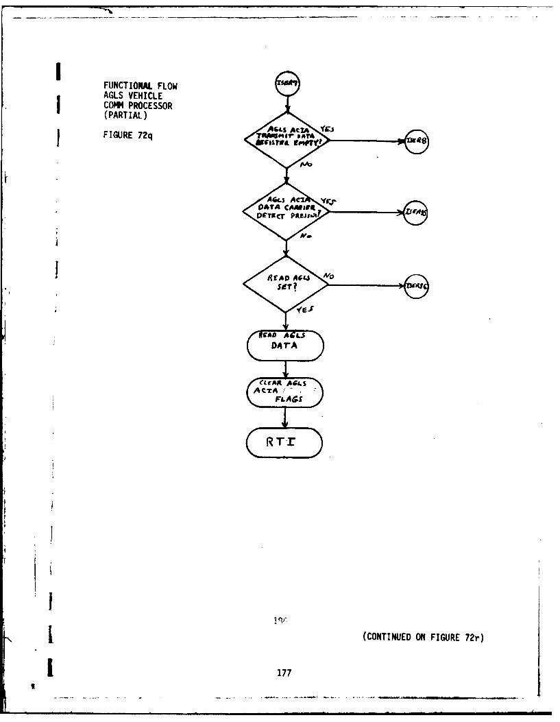
FUNCTIOAL. FLOWAGLS VEHICLECOMM4 PROCESSOR(PARTIAL)
1FIGURE 72q O otrnr
1 01
j ~ ~ ~ ~ ~ ~ AL (CNIUDOAIUE7r
04 C177

FUNCTIONAL FLOWAGLS VEHICLECOMM PROCESSOR(PARTIAL)
FIGURE 72r AL
RT
Yes
wi#71 ATA
C1780

~~~~'*1.
FUNCTIONAL FLOWAGLS VEHICLECOM MRCESSOR(PARTIAL)
FIGURE 72s soiro S.
£3
c ftr Bury m*
'(as
AtrA
(CONTINUED ON FIGURE 72s)
179

ADo-A97 521 HOEYWELL INC HOPKINS MN DEFENE SYSTEMS DIV PI 19/6AUTOMATED SUN LAYING SYSTEM FOR SELF-PROPELLED ARTILLERY WEAPON--ETCMAY 80 E E LENTOLA. K A HERZIN DAAAO9-T7-C-02S
UNCLASSIFIED #6
'III.IIIIIIIIIIIIIIIIIIIIIIIIEIIIIIIIIIIIIII
on-MENOMONEENI

1101 I02IIll1111112.0
11111 25 (i 1.4
MIUROC(C,'Y RI S1IU (N 11',1 (HARI

FUNCTIONAL FLOWAGLS VEHICLEfCOMM PROCESSOR(PARTIAL) C ~ v
FIGURE 72t :?
01tT__ AIA l
REi 53~ DT
R"FSTD4 IL
TaAA~e'~ IT g~
* r
TI
r 80 1ek Yr

After the configuration was defined, a software specification was generated,
briefly as follows:
o Three software timers counting from 0 to 159 shall be provided each
with a status bit and a cycle counter counting complete cycles from 0
to 7.
o A timer will be started on the first "XP pulse immediately following
"S" pulse, if no other timer is at count 159 and active.
o If a timer is at count 159 and active, and an "S" pulse arrives, that
timer stays active and rolls over to count 0 on the "X" pulse immedi-
ately following the "S" pulse. Its cycle counter will be incremented
if not at the maximum value of 7.
o If a timer is at count 159 and active, and an "X" pulse arrives without
a preceding "S" pulse, that timer goes inactive, and its cycle count is
cleared to zero.
This software configuration ensures that an erroneous reference angle can not be
computed; and the correct count can be determined by examining the cycle counter
and status bit of the three counts.
One additional check is to verify that either the 'S" and the "L" pulse are
alternating, or they are coincident. If true, and if at least one counter is
active, the processor determines that a good GACS measurement exists.
The total reference angle is computed by the above counter, plus an interpolation
which resolves the time interval during which the LASER is detected. The refer-
ence angle then is determined to be:
40 TL
Output = 40 x (count) + T----TL
where: Count = Value of counter with highest value in cycle counter
TL = System clock cycles from last "X" pulse to "L" pulseTX = System clock cycles from ("X" pulse preceding "L" pulse)
to ("X" pulse following "L" pulse).
181

!The software flow diagram for the RU program is shown in Figure 73 and the
associated assembly level source code in Appendix C.
7. Fire Direction Center Communication Processor (FDCOM)
The fire direction center located function of the add on scope of work consisted
of the FDC communication processor interfaced to the FDC PDP-11/34 computer.This processor provided two-way communication between the FDC and VECOM. The
processor was mounted in a 6" high rack cage assembly to facilitate installationin ARRADCOM's Automated FDC trailer. A functional block diagram of FDCOM is
shown in Figure 74 and the corresponding schematics are contained in Appendix D.
This processor used the common board set H-10 microprocessor system which allowed
complete interchangeability between it and its vehicle mounted counterpart. Oneunique circuit card was fabricated for FDCOM that being the PDP-11/34 interface
board. This board was required to make the respective system I/O port electrical
characteristics compatible.
On system power up (or RESET) FDCOM goes into the STANDBY mode. In this mode the
receiver circuits are enabled waiting a SELECT or sign on message from a vehicle-
borne VECOM. Upon receipt of a SELECT the message is checked for validity and an
acknowledgement is sent to the vehicle. The line-turn around message is then
sent to place the vehicle processor in the slave mode and FDCOM in the master
mode.
When a message is received from the FOC computer the transmit sequence is
initiated. The first message out is usually the gun order, which is returned
upon acknowledgement by the Chief of Section. If another gun order or check fire
has not been received by FOCOM from the FDC computer in the interim, a ready
request is sent to the vehicle. If either the gun order update or check fire was
received from the FDC computer, FOCOM sends that next. All acknowledgements from
the vehicle and the data messages that go with them are made available to the FDC
computer via an interrupt driven output buffer.
For checkout purposes, or in case of FOC computer failure, a background package
was written for FDCOM that allowed entry of gun orders and display of vehicle
responses via a terminal.
182

REFERENCE UNIT PROCESSOR EItO0I FUNCTIONAL FLOW UA#ir PAOtE.SSt(PARTIAL) P*V6QAM ur~
Figure 73a o it ovm r
T'i m~ M
Cl-lcAf FLAG.A,'O COMISrM,1
So FTwuA
CLC A04jauF FE S
ti, LITERFS L couiv r
RUI (Continued on Figure 73b)
183

KV1l
REFERENCE UNIT PROCESSOR rvltFUNCTIONAL FLOWT
I MIKA0 or(Partial) 3 SAISCC
Figure 73b LIZ
fcr A0iw rT
PeLie
Si IA. TefE
(Continued on Figure 7A)
1843

tL10
REFERENCE UNIT PROCESSOR frr GLIFUNCTIONAL FLOW
(Partial)
Figure 73c c.writeL.CAC.S! LAMPb
I:Vfv? LA MV
SrTI
I (C~~~~~~oniudnFiue7)
81IST1 185
TJeW OFFr

RU2
REFERENCE UNIT PROCESSOR car orFUNCTIONAL FLOW '-?ULOE r FROMR
(Partial)
Figure 73d
(Cotiue oFgre7e
1863,CvT

REFERENCE UNIT PROCESSORFUNCTIONAL FLOW
(Partial)
Figure 73e
(nn u oFu
187 f rE
PER0o -mss)y'rrm
RV (Continued on Figure 73f)
~187

'ET X P VLSIrREFERENCE UNIT PROCESSOR pEA. o Lse
FUNCTIONAL FLOW(Partial)
Figure 73f
OUfTx I PE * 1S
AO
r=O' OuT-f
L13 (Continued on Figure 73g)1
188J

Lt3
sraAa. 4,6REFERENCE UNIT PROCESSOR I u~o,~
FUNCTIONAL FLOW(Partial)
Figure 73g L pj
YeI LL ~ (Coninue on igur 73h
189Cov

REFERENCE UNIT PROCESSORFUNCTIONAL FLOW
XH PvT 3(Partial)
Figure 73h
V@
19
LAM P$sSCT?0
y ' cs
(Tnine on itur AO3tA,
LAfm0P
I . ... .. . . . .... .

REFERENCE UNIT PROCESSOR Az- mmlTFUNCTIONAL FLOW AZ DIL+ sE r
(Partial)
PFigure 731 ?40 0esw re o4
jfi
CoyAzm
IvU 191

L'7
A/0REFERENCE UNIT PROCESSOR FDc
FUNCTIONAL FLOW s :r(Partial)
Figure 73j
O4RO. To
12
B ASF a
SDEKL eCTIOMA
{TO CreforT A~A0D'X s FLAY
[OF LAMP' d"
(Continued on Figure 73k) (
192

LIS
REFERENCE UNIT PROCESSOR A'0FUNCTIONAL FLOW r p
(Partial)
Figure 73k
Asv.LC TroDISPLAY
G F-T A094 oUOF LAM~P ONP
C oivTA 0 LOPF'RATf
L0
193

IREF UNAITPot ecess ol
REFERENCE UNIT PROCESSOR :NrexoFUNCTIONAL FLOWE
(Partial) r
Figure 73t
94

REFERENCE UNIT PROCESSOR %TrE0A
FUNCTIONAL FLOW zr
(Partial)
Figure 73m LF~, N
SET?
RFA -',C I

'I.T
REFERENCE UNIT PROCESSOR X USFUNCTIONAL FLOW r AT
(Partial)
CLIFAI LFL.A~Figure 13n C L FAOL74
RT
CLOA AL Go C
CLE40t CQFL4
1A/C LGo4E
fit i
(Continued on Figure 73o)I
1 96

'sl
REFERENCE UNIT PROCESSOR u'PDATEFUNCTIONAL FLOW co v o ro&s
(Partial)
CLr4A SMFL.Figure 73o CLEAR L.VL46.
CLEAak LBLocic
CLFAR plAf
IC'A1L
I 197

REFERENCE UNIT PROCESSOR NFUNCTIONAL FLOW CS3
(Partial)
Figure 73p
0-^ P 5I
UOAT f
/CrF4o. LISLOe
. .-.
"-Nt
198

REFERENCE UNIT PROCESSORFUNCTIONAL FLOW
(Partial)
Figure 73q pP, T A
pvL r9
RTT2
CS3 MS
PVLSIV
199

ISE
REFERENCE UNIT PROCESSOR CLEAA CFLAGFUNCTIONAL FLOW CLrAsk Timr.Es
(Partial)
Fiue73r c~rAi L6oom~FigreCLIFAA V.-A3
(Cnine onFiur7s
2004

:rsz
REFERENCE UNIT PROCESSOR ALIs, romiD 4.FUNCTIONAL FLOW FLAGS
(Partial)
Figure 73s +~T
srRIJ
CLEAR~ ranf~z.FLAG
Coue.' r- SCA'1
2010
SIAITO

BEA
REFERENCE UNIT PROCESSOR GET' u
FUNCTIONAL FLOW PULsr Coud"7(Partial) (L SOB)
Figure 73t c rTO
$O,*T#4 put es.
cooot
12
LA11Wi PULSFVALVE
PVLSE
11Rrr
202i

REFERENCE UNIT PROCESSOR ACT-A t'VTFUNCTIONAL FLOW kvx SEl?
(Partial)
Figure 73u
R T
I
1203

PRo SS
REFERENCE UNIT PROCESSOR 1tAW MITTEDFUNCTIONAL FLOW DATrA
(Partial)
K rrFigure 73v
204

PROCESSOR MODULE PARALLEL
MICRPROCSSORADDRSS-ADDRESSMOTOROLA M6802 DATA -DATABUFFERS 'v---BUFFERS
TIMER
PROM M6840
83KBYTES
2716SERIAL SERIAL
INTERFACE CLOCK6850 1441 S PARALLEL
y INTERFACE
S 6821TE
RS-232 MINTERFACE
SS
SERIAL COMM MODULE POWER SUP
MACE~ 7DT REGULAT,
CLOCK lCONTR
R PARALLELA COtMUNICATION 1/0D CONTROL &
I- SP+YSFDCOM PROCESSOR
LINE 205 EJ

PARALLEL INTERFACE MODULE
s PARALLEL PARALLEL PARALLEL PARALLELyINTERFACE INTERFACE INTERFACE INTERFACE
s 6821 6821 682 6821TEM
BUSS
PARALLEL 1/0 DEVICESPOWER SUPPLY MODULE
- RGIATRS FILTER 10 VOLT
PARLLE 8 BIT BI-DIRECTIONAL
MPROCESSORSEE COTL
205 FIG E 714- m,.

Ij Status displays are provided on FDCOM to allow monitoring of the communication
sequence; the meaning of each is:
NAK = Negative acknowledgement of message received, retransmit
requested.
DCD = Receive data carrier detect
FDIN = FDCOM is receiving message from either FOC computer or terminal
(background)
FDOUT = Data received from vehicle is available for output
CJ=3 = FDCOM is unpacking received message
CJ=O = FDCOM communication link is idle
COM = Communication system is connected between vehicle and FDC
STBY = Communication system not connected and FDCOM is ready to accept a
select
In the connect sequence we have shown how VECOM initiates a data exchange se-
quence with FDCOM. During this sequence the roles of the respective processors
are interchanged; that is, VECOM goes from an active to passive state and FDCOM
from a passive to active state. The disconnect sequence again reverses the roles
and can be initiated from either end of the link. The disconnect is initiated at
VECOM by momentarily switching to the STANDBY mode. This action sets a flag in
the processor and when the next message is sent from FDCOM a request for discon-
nect (RFD) is returned.
The RFD results in a disconnect command (DIS) being sent back to VECOM whose
response is to switch to the STANDBY mode.
The disconnect can be initiated at FOCOM by issuing an end of mission command via
the FDC computer interface on background package. This message results in a
i206
i

f
disconnect being sent to VECOM and a switch to STBY mode by FDCOM once the
message has been received by VECOM.
The software designed for FDCOM is shown in flow form in Figure 75 and the
associated assembly level source code is contained in Appendix E.
B. Automatic Gun Laying System Processor (AGLS)
As indicated in Figure 8 communication between VECOM and AGLS is via a bidirec-
tional RS-232 serial link. Since the original source of gun order data was via a
parallel BCD interface to the GACS Gun Unit, changes were required to the AGLS
program.
The operating sequence of the AGLS was modified as follows:
o All gun order data is received and operating data reported via a bi-
directional serial data port.
o Back up gun order data entry via thumb wheels will be provided using
the existing GACS data port.
o AGLS Status word added to the COMM buffer (mode).
o Separate error bound test routines are used for level and tracker
status and tracker/quad pitch null tests.
o The system now has the ability to operate on one set of gun orders and
display the new (command values).
o New gun orders are latched In with a single switch movement. If in
AUTO Az or El mode, the new gun order is latched in via WPN switch; if
not AUTO Az or El, the gun order is latched in via SERVO switch.
o Load position is selected at any time in AUTO El mode without any other
switch motion. Return to QE is also automatic; i.e., no other siwtches
involved.
207

AGLS COMMUNICATIONS FIRE DIjtFcrloAfFIRE DIRECTION CENTER 0-rrs potoctSimCOMM PROCESSOR poor,"m smtrAFUNCTIONAL FLOW Po~kV l(PARTIAL) Am
FIGURE 75 a zPit
ZOLe VffCv*O%FLA&~
Tow,rr ww.8IL
TI MIAS
LrNASL
F i'AiLEoAer.a So''TwreAAv~S
CLCAA 1e0SW
CLIFA$E (CONTINUED ON FIGURE 75b)
200

FDJ1
ThEA' O&V
AGLS COMMUNICATIONS5 meY
FIRE DIRECTION CENTER L-ro
COMM PROCESSORFUNCTIONAL FLOW ruotov oF'p(PARTIAL) Com
FIGURE 75 b C
rA'Mt r
(CFINE OVN tIUR 75Hit -l 29
IL

AGLS COMMUNICATIONSFIRE DIRECTION CENTERCOMM PROCESSORFUNCTIONAL FLOW(PARTIAL)
FIGURE 75 c
1 0
sr/ P
x MrMCNINE ON FIGUR 7d .
ro/10i~

AFLS COI9IMWICATIO4SFIRE DIRECTION CENTERCOM PROCESSORFUNCTIONAL FLOW L5(PARTIAL)
FIGURE 75 d
L 2L14

AGLS COMMUNICATIONS AGLSFIRE DIRECTION CENTER Dr.#E ViRECTIVECOMM4 PROCESSOR CF#VT~f PPOCM09~
FUNCTIONAL FLOW rTTWAUpt fff0*vlf
(PARTIAL) RoT,
FIGURE 75 e
ir6fi1 IgTAcfr
TN r SAVE'S
Ivarimin FLASET?
(CNIUEWNFGUEs1
21iag J

AGLS COMMNICATIONSFIRE DIRECTION CENTERCOW9 PROCESSOR pnFUNCTIONAL FLOW v tA vic r04 2(PARTIAL)
FIGURE 75 f
Rrr
R TI
(CONTINUED ON FIGURE 759)
-I 213
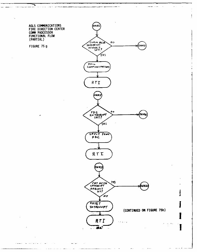
AGLS COMMUNICATIONSFIRE DIRECTION CENTERCOMM PROCESSORFUNCTIONAL FLOW(PARTIAL) omAi
FIGURE 75 g 0 FaugSI
T,.,
(CONTINUED ON FIGURE 75h)
Sr-TI
T.&p~*1

AGLS COM14JNICATION4SFIRE DIRECTION CENTERCOMM PROCESSORFUNCTIONAL FLOW CTAA1(PARTIAL) qcoUE MDA
FIGURE 75 h
ATA
Rll
NTIr YrI-twpl~ A Al
215's~r

In addition to these changes, the reference angle computation algorithm was
changed. Rather than accepting a COMMAND azimuth that is the sum of the FDC gun
order deflection and the reference angle, COMMANDED azimuth is accepted and
displayed directly. The reference angle data from VECOM is subtracted from the
absolute encoded pantel reading to make the ACTUAL azimuth display compatible
with the COMMANDED value.
The new assembly level source code listings reflecting these changes are con-
tained in Appendix F.
216

I APPENDIX A
SYSTEM AND CABLING-AGIS
0I... j

a z
do 0 ~ ~ ~ ~ h3 4'
I-i
;' A* 3 tI
00 0
~i ~ I ~ ~q C
a LaLi A a 4
FbA~a ! 4 O - I~
cC Z S 4 (h~9 le

APPENDIX B
AGLS FUNCTIONAL FLOW
I

7 Aj\~ ~ ~
CoW~ 0"-
a.
~~ooP *?..
~ A~
I ~LTRW-~
'~ ~
hi
4~A~ bA~z~A~
LoA~bPc~ I
T
~ ~ ~
'N ~

Ar4L
(aI' - A

A wqIFa
Iy
-a-~ .A. WOE

K3V I
lyI
I _ _ - s

9 ~4 a.Ur
bL

At,
"*AD
AC%
wi7

I
APPENDIX C
AGLS CONTROL PROGRAM FLOW DETAIL,
KEYED TO LISTING OF APPENDIX B
Ih
• "I I, o~ -

T T
41

AG 7t7-8
P.1..DI
AC
P. b.
P.EA.
P-S.0041 A
ikvjc Sf
2 ps

AGI 4S
F- IEAV.
c-A - Al
4 EL F VA1-

Sc -r p :~
yf

p.-TAS! APC-d- =e
A C, FvjFW F
A .IPio
1 57
P, T. A_ _-Q

AIL~ltop

1-1 A
rI-,'IA
A--I r>
6 -
~A t
2UA.3rc
.T1U J 7

Vy..
A Cq

44
1 19

10

'-43
irP
1y
~ . __ _____-A ..

ArS4S
12

13

ki LI-?i%R1
Slap

1-2

II
1 1-3
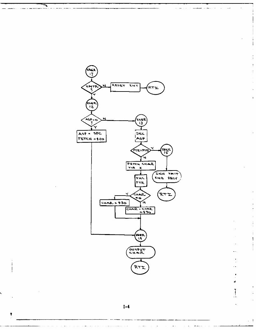
x~ MT
134
IAAZ
D ___________________________ - - - - __________

APPENDIX D
AGLS CONTROL PROGRAM SOURCE LISTING

PAGE 00i AOLS PAGE 002 AGL5
00010 NAM AGLS 050 21 I6AEU PAU.00020 OPT 005 46 PI6)EU P 6A00030 * REVISED 3/28/78 00560 2417 I'1A6CB ECU PIA6DA.300040 * CRT DISPLAY OPTION 0057000050 * *p PIA7-D/'. CONVERTER00060 **********AOLSI****** 05ojV00070 *P3*A EQUATES 000 2418 PIAlDA EOU $24180 8000610 2419 PIA7Db ECU PI A7DA+ 100090 PIAO-AUTO SAIITCHES().CLOCK RATE(S) U0620 241A P-IA7CA ECU PIA7DA*2Jo1000630 2418 IA7C8 EOU PIA7OA+300)30 2800 PIAODA EQU $2800 00640
0010 20 PAD Q )AD~ 0650 *P[48-DISPLAY(4) AND 5.11 CMiES(4).(A)0032 281 PIODBECU IAOA*I00660 * MISC INPUTS(3) A14D DISP AflDR(5),(8)00130 2802 PIACCA ECU VIAODA,2 0067000 14C 2803 PIAOC9 ECU PIAODA.3 00680 241C PIA80A ECU $2100)50 $20402)0 P1CBEC IAO.00~ 16 PIAI-GACS LSB(A).GACS MSBOI) 00700 241D PIABCA ECU PI A8)A.2IJ0170 000*4E PACAEU PAD+Jo0180 2400 PIAIDA EOU $2400 007310 241F PIABS ECU PIA8DA+301090 2401 PIAID8 ECU PIAIDAl 0072000200)( 240? PIAICA ECU t'IAIDA+2 00730*0)0210 2403 PIAIC3 ECU PIAIDA.3 00750 01 *WTC AK30220 U05J0230 *P1A2-OUAD EL ENCODER1UMSS=A.LSB-B 00770 0040 LOPIU ECU Xl100000000n240 *00770 0040 LPRO E)u X1I0OOGO30250 2404 PIA20A ECU $2404 00790 0020 CLROM ECU Xl100000U0260 24 - PIA2D8 ECU PIA2DA*I 0090 0010 PCIRQ ECU Xl00000 02 70- 2406 PIA2CA ECU )')A2DA.2 001,3)0 0004 OlROA ECU %1000)02F50 24t)7 PIA2Cb ECU PIA2DA.+3 080 00 LC C
j0300 V PA3-PANTEL AL ENCODERIMSB-A.LSO*8 00840 001 ERMEU Aj0310 00400120 2408 PIA3OA F(00 $2408 00850 P IA 0 STROBE00133L; 24o9 P1A308 ECJU P)'.3DAl 00860 2802 PwnfoG ECU PIAOCA)0340 240. PIA3CA ECU PIA3DA.2 00870"0351, 240B PIA3C0 ECU PIA3DA.3 00880 P CA) ENABLE ADDRESSES10361., 00890*(3370 C PIA4-1/l0 ENCODER OUTPUTS(A),ENABLE )UTPUTS(8) 00900 2403 OCSA7 ECU ' PIAICAJ0380 001 43 GS7EU PACJ0390 240C PIA4DA EQU $240C 00920004010 2400 PIA408 ECU PIA4DAl 00V30 *P!A4 (Al INPUT MASKS0 04)1 240E PIA4CA ECU CIA4DA.2 039401042 240F PIA4C8 ECU PLA4DA43 00950 00OF ELTM ECU %fill400960 001 0 A ZTM ECU XIIIICOCO
* PI5=MU A/ DAT (A).MU ADOIB)009704 ,PA-U / AA()MXAD()00980 * PIA4 (8) ENABLE BITSj0450
009J04'1,, 2410 PIAOUA EJU $2410 090* 0=T.CUE,,4 1, 2411 PIOD)8 ECU PIA5DA.) 03000
)4 4 PI5AEU I5A201010 OOFE PLuo ECU X11111110'0" 2413 PIA5CA ECU PIA5DA.2 01020 00100 000) ECU A11111101
01040 OOFB PAO ECU 411110l)* rI'6-EL IUN A/D(A).AZ IRIM A/D(BI 01040 001E7 IP00 EQU X111101l
241 POl6oA EU 21 000 DF OG)) ECIU X11)01111244 ,.0 I241414 01070 006F AZGO EQU ).01111111. 4s iAoD) ECU IIA6DA.l 01080 007F ELcE) ECU )ll)
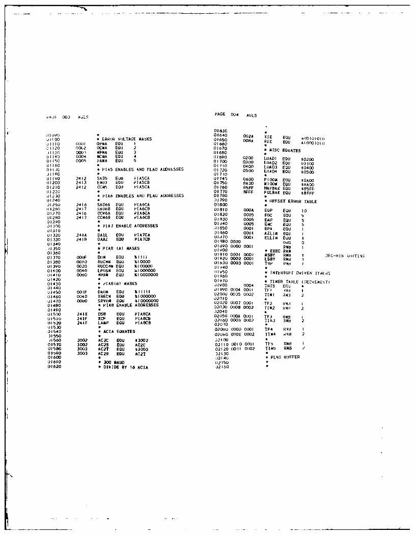
tA;E 003 A6LS PAGE 004 AGLS
01630
0109* 01640 002A XIE EOU /0I001010
UIICX ERROR VOLTAGE MASKS 01650 008A PIE ECU 4lo000101J3930 0001 OPMA EOU 1 01 66001120 00(,2 QCMA EQU 2 01670 * MISC EQUATES113G 0001 MPMA EQU 3 01680
U1140 0004 MCMA ECU 4 01690 0200 LOADI EOU S020001150 0005 PARA EQU 5 01700 0300 LOAD2 EOU $030001160 * 01710 0400 LOAD3 EOU $04000 1 7C * PIA5 ENABLES AND FLAG ADDRESSES 01 720 0500 LOAD4 EOU $0500J1 80 01730 *
I93G0 2412 SAD5 EU P-IASCA 01740 OAO0 P100111 EOU $OAO01200 2413 EMUX EOU PIASCB 01750 8A00 /4100 EQU $8A0001210 2412 CCN5 EOU P[ASCA 01760 85FF HAFBAK EQU $85FFL1220 * 01770 8FFF FULBAK EQU $8FFFJ1230 * PIA6 ENABLES AND FLAG ADDRESSES 01780 *01240 * 01790 * OFFSET ERROR I-ABLEJ1250 2416 SAD6A EOU PIA6CA 01800 *01260 2417 SAL)6B ECU PIA6CB 01810 OOOA EQP EU 1001270 2416 CCM6A EQU PIA6CA 01820 0005 EC EOU 501280 2417 CC/68 EQU tIA6CB 019830 0005 E4P EQU 501290 * 09d40 0005 EC EOU 501300 * PIA7 ENABLE ADDRESSES .1850 0001 EPA EOU I01310 * 09I360 0009 AZLIN LOU I01320 241A DAEL ECU PIA7CA 1l870 0001 ELLIM EOU I01330 2418 DAAZ EQU PIA7CB 17 0 0 000G GOOG 3) 001340 * 01090 0000 G0 RMO I) O350 * PIA8 (A) MASKS 09000 * EXEC RAM I03360 * 0190 000i 0001 MSBY R4MB I DEC-HIN kU'ITI!E01370 GOOF D)M EOU %fll 01920 0002 0009 LSBY R/ti 301380 0010 RUCWM4 EQU I0000 01930 0003 0001 TtAP (4, 301390 0020 RUCCOIM EQU Z00000 Vi 940 *01400 0040 LPOSM EQU i91000000 01950 * INTrEHRUPt DRI[VEN TI.lrS01410 0080 I,PNM EQU %I0000000 U1960 *01420 *0197U TIER TA'LE (JEChiLM NTI01430 * PIA8(d) MASKS 0I900 0004 TIMTB EU L,01440 * 19980 0004 T LOU I
001450 0F DAOM EOU 1l 01990 0004 0009 WI d 11)1460 0040 XREC ECU XIGGO00 02000 0005 0002 TIMI ,43 203470 0040 XRV(3 EOU %1000000 02010 *0J1470 0000 SRVI EQU 110000000 2020 0007 0001 TF2 Phi01480 * PIA8 ENABLE ADDRESSES 02030 0008 0002 TIM2 u3,14 201490 209500 241E DS8 ECU J98C 2040*PIACA 02050 000A 0001 TF3 RMS 101510 241F XCF EQU PIABCB 02060 000h 0002 T[13 R/MB 201520 241F LAMP ECU PIABCB 02070 *,j153031540 * ACIA EQUATES 0200U 0000 0001 TF4 RN18 I
)1550 * 0200 OOOE 0002 TIM4 R3B 231560 3002 AC2C EOU $3002 J210 *01570 3002 AC2S EOU AC2C 02110 0010 0001 TF t, RM 101580 3003 AC2T EQU $3003 02120 (0I 0)02 TIN M4 RMB01 :90 3003 AC2R EOU AC2T 32130 *01600 02140 * FLAG BUFFER01610 * 300 BAUD 02:50 *09620 * DDIV.E BY 16 ACIA J2 60

I
PAjE 0(,, AuLSPAGE 006 AGLS
o2170 0013 BE£. EuU02;60 0013 00(1 OL P RU 02710 ,0213U 0014 0001 02720 004F 0002 AZCoM Rud 2A2200 00344 0001 ALGoF 3,3d 02730 00 0002 ELCOM RMtU 2,)2200 0015 0001 ELoF 'MB 02740 *0220 036 1 0001 hPNF RUB 1 02750 0053 0002 AZERR RUB 2022002160 0055 0002 ELERR RB 202230 0018 0001 LPOSF RM I .2770 0.)2240 j)(lI 0003 XTHRU (U 1 02780 0057 0001 AZCNT RUM I02200 O01A 0001 IDLEF Ru I00U22) (0 1,1 0o0 RUCUF RUB 027(90 0058 0001 ELCNT RUB 2)2270 001C 0001 STF RMB 1 02300 0059 0002 OPCNT RUB 2L)22),,00lb 0001 TdLK R4A 02910 0058B 0002 TRCNT ROB 2U2290 0031E 0001 PC3LK RM 1 02820 005D 0002 TRLP RUB 202 3')c L)0 03 n):)l ELLKI R43 1 02830 005F 03301 XTIUE RUB IJ201 1 G 3 00 OU AZLKI ,.,b 1 02840 0060 0002 OPLP RMB 2). C0( 21 GOO AiLLK2 ¥8 1 02850 *)21300 X,22 0001 AZLK2 RMB 3 02860 0062 0002 Al RUB 2',2 340 0023 0001 DEL4 RUMB 1 02810 0064 0002 A2 RUB 2,,23 (3023 00UDr4 U 2880 0066 0002 SI RUB 202 0024 00l RUCCWF RMB 1 02890 0068 0002 S2 RUB 2L'.. ')02) U00I AkEDY RMB I 0290 006A 0002 x R.B 21,'0 30 /u0 0-,2 0'iU I2I R,23,hQ 0026 0(0l S30 RB 1 02910 006C 0002 X2 RUB 2,23,,0 0027 0(03I CI(3F RUB *0? iv,) 0028 0(01 NbOF ,d148 029200)2-4,' 0 0(2v 00031 LLoWF RUB 1 02V30 006E 0002 O)UTX RUB 23241 '3 0( 2A 0001 DTHRU MB 3 02940 0070 0002 FIOLDX RUB 20 242c 0021 OMul DISEL R4B 102950 0072 0002 TIZX RUB 2,2430 , G2C 0001 DISAL RUB 1 02960 0074 0002 STORX RUB 2_2440 2 0 02970 0076 0002 ADDXI RUB 2J2.4'0 00(21) 0001 CONGO RUB 3 02980 0078 0002 SUBXI ROB 2J24e3) 002E 0001 CONTEU RUB 02990 007A 0002 SUBX2 RUB 2)2410 1)o,) 0001 AZTRM RB I3000 007C 0002 TX RUB 2J2480 0030 0001 ELTRM ( ,Md I 3010)2490 0031 0002 EL3CS RUB 03020 007E 0001 CNX RUB I
RU2'B) ,)33 0002 AZ2CS RMB8 03030 007F 0001 OLOAX RUB IJ2*jl1 * ERROR VOLTA2E BUFFER 03040 0080 0001 OLDbX RUB I
j - 20 O)3, EkWBUF EOU U 03050 0081 0001 THI RUB I(03:; .) 007 RMB 7 03060 0082 0001 TLC RUB I0'0o~ (.' 3C 0003 I MUXADO R.43B 1 03070 *
.)t"() 00(30 0001 NUMRED RUB 3 03080 0083 0001 H)LDB RUB IJ02'"60 (333 03(03 PREVAL RUB 1 03090 0084 0002 KEEP RUB 2)2.,1u 3)OJ3- 0001 LITE RU8 1 03100 0086 0001 TF RNO I02"43) 0040 0001 FFLA0 RMd 1 03110 0087 0002 GACTEU RMUl 20 "'j * INTERRUPT SERVICE ROUTINE FLAGS 03120 *J2 )00 ('41 0001 ELDAF d,4, 1 03130 0089 0001 SAVA RUB I052' 30 W042 0001 AZE.AF RM 8 I 03140 008A 0001 SAVB RUB I(e. 1u 00,43 (;')03 DISADR RUB I 03150 * DISPLAYS BUFFER,2 ,30 00(44 00302 ACT RUB 2 03160 * ELEVATIONQ2'540 0040 0001 PASSAZ RUB 1 03170 * GACS,2',0O 0(347 0001 PASSEL RMB 1 03180 008b 0005 ELOCDS RUB 502060 M 48 0002 PTR ROWB 2 03190 * ENCODER0,100 14O(.A 0002 PTE RMB 2 03200 0090 0005 ELDISP RUB 5,)26'0 0(,4A 0002 SPC RUB I 03210 * ERROR026Y0 03,43 0001 ASP RUB 1 03220 0095 0005 ELERD RUB 50271,0 004 0001 XON R4B 03230 •
03240 *
i,.

PAGE 007 AOLS -A,AI 0)8 AuL';
03250 * AZIMUTH u3450 T
03260 * GACS 03460 AGL5 CONTROL PROGRAM
03270 009A 0005 AZ0CDS RM8 5 03470 E
03280 * ENCODER 3480 ENTERi EWE ON RESET03290 009F 0005 AZDISP RMB 5 03490 4(00 ORG S4000033 00 * ERROR 03200 4000 AGO EOU *03300 * ERROR 03510 4000 3E OFFO LDS #$OFFO03310 OA4 0005 AZERD RUB 5 03520 4003 CE 4A36 LUX .ISER03320 03530 4006 FF OFF6 SIX SOFF603330 * OFFSET ERROR WORDS 03540 * INITIAL PIAS03340 OOA9 0001 ELLIT RMB I 03540( H 4 N6 TAL PIAS03350 OOAA 0001 AZLIT RUB 1 03550 4009 CLE' 4968 JSR PIAS03360 * TEMPORARY BUFFERS 03560 * CLEAR TIMERS03370 OOAB 0005 TEMSUB RMB 5 03570 400C BD 4C27 JSR CLTM
03380 ooeO 0005 TEMBCD RMB 5 .)3580 * CLEAR FLAGS
03390 00B5 0005 RESULT RUB 5 03590 400F BD 495C JSR CLFG
03400 OOBA 0005 ELTEMP RUB 5 03600 * SET DISPLAY INTERVALS03430 0BF 0005 AZTEUP RUB 5 03610 4012 CE 0014 LDX #2003420 0084 0005 ADJX RB 5 03620 4015 DF ') STX TIMI03430 0009 END EOU * 03630 4017 CE 00C8 LOX 0200
03640 401A DF 08 STX TIM203650 401C 7C 0004 INC TFI03660 401F 7C 0007 INC TF203670 4022 OE CLI03o80 * TEST IDLE BREAKOUT
03690 4023 IF 0042 A02 CLR AZOAF03700 4026 IF 0041 CLR ELDAF03710 *03720 4029 IF O0E CLR ELK03730 402C 7F 03 CLR T3LK03140 402F 7F 005P CLR OPCNT
03745 4032 7F 005A CLR UPCNT+I03750 4035 7F 0056 CLR TRCNT03755 4038 7F 005C CLR TRCNT+I03760 403b 7F 005F CLR XTIME03770 403k 7F OOC CLR STF03780 4041 7F 001F CLR ELLKI03790 4044 IF 0020 CLR AZLKI
03800 4047 IF 0021 CLR ELLK203810 404A 7F 0022 CLR AZLK203820 4040 IF 0023 CLR DEL403830 4050 IF 0046 CLR PASSAZ03840 4053 iF 0029 CLR SLOWF03850 4056 7F 0016 CLR UPNF03860 *03A70 4059 IF 001B CLR RUCNF03880 405C 7F 0024 CLR RUCCNF03890 *
03900 405F 7D O01A TST IDLEF03910 4062 27 2C BEg AG4603920 * COME FROM LOAD POS?
03v30 4064 7D 0018 TST LPOSF03940 4007 26 00 BNE AG5
03950 4069 7D 0013 TST OLP03960 406C 27 30 BE0 AG6

PAGE 009 AOLS PAGE 010 AGLS
03970 406E 7F 0013 CLR oLP 04500 40D7 26 08 BNE AGIO
03980 4071 7C 0016 INC NPNF 04510 40D9 BD 4650 JSR COAIPAZ,J3v90 4074 20 OF BRA A028 04520 40DC 7C 0019 INC XTHRUJ4000 A 04530 40DF 20 06 BRA AGII04020 4076 7F 0013 I05 CL OLP 04540 *04020 4079 7C 013 IrC OLP 04550 40EI BD 46E4 AGIO JSR COMPEL04030 407C 20 12 cEE A A46 04560 40E4 7F 0019 CLR XTHRUJ4U40 •ESET N SERVOI SW. 04570 * READ AND STORE ERROR VOLTAGES04050 407k 86 80 AG6 LUA A #SRVOM 04580 40E7 BD 4482 AGII JSR RAEV34060 4080 8D 44C5 JSR TSTSB 04590 * CHECK OFFSETS
,)4170 4083 25 OB BCS AG46 04600 40EA BD 4579 JSR CKOJ40PO 4085 7F 001A AG28 CLR IDLEF U4610 * TEST SERVO SW0)4090 4088 7F 0017 CLR XRECF 04620 40ED 86 80 LOA A # SRV
41 00 408B 86 FF LDA A *$FF 04630 40EF 80 44C5 JSR TSTS81)4110 408D 87 240D STA A PIA4DB 04640 40F 2D4 80R ASS804120 * READ CONFIG SWITCHES 04640 40F2 25 08 BCS AG47
04130 4090 BD 4390 AG46 JSR CONRQ 04650 40F4 06 FF LOA A f$FF
)4140 * FORM CONFIG WORD 04660 40F6 B7 240D STA A PIA4DB,)4150 4093 BD 431F JSR OCE 04670 40F9 7E 4023 JMP AG20)416 * READ 4Z AND EL TRIM 04680 • TEST IDLE FLAO14160 409 43A AD Z ANDETRM 04690 40FC 7D O01A AG47 75T IDLEF
04170 4096 80 43A3 AU? JSR RTRM 041U0 40FF 27 03 BEG A039J41lO * READ AZ AND EL GACS 04710 4101 7E 4023 imp A,20'"') 4099 7F 0028 CLR DISEL 0410 41SET 0U JLAG0: 1 409C 868 D 5VN04720 '*SET RU FLAGS
C86 80 LDA A SRVM 04730 4104 B) 44D7 AG3V JSR SRUF0' 409E 8D 44C5 JSR TSTSOB 04740 * WEAPON AL ENABLED?j..i0 40AI 25 03 BCS AGB 04150 4107 7F 0042 CLR AZDAFJ4220 40A3 BD 4419 JSR RGACS 04760 410A 7C 0042 INC AZDAF,)4230 * SWITCH GAX SELECT 04770 410D 7D 0014 TST AZGOFJ4240 40A6 86 36 A08 LDA A *$36 04780 4110 27 35 BEG Aj1204250 40A CO 3E LDA 8 *$3E 04790 TEST START THRU FLAG04.'o(; 40AA 87 2402 STA A GCSEL 04 40 • TST ST F)4210) 40AD F7 2403 STA B GCSAZ 0480 4112 7D 001C TST STF
)42"2 4080 7D 0019 TST XTHRU 04820 4115 27 03 duo AG3704,190 40d"3 27 06 BE-) A044 u4820 4117 7E 41~C J.mp A*I6,4300 4086 27 2403 STA A GCSAZ 04.130 ' TEST XENON ON)4313 4068 F7 2402 STAB GCSEL 04840 411A 7D 0017 AG37 TST XRECF04320 Fl240 TESTA P GEL04150 41D 26 03 BNE A032
04320 4 TEST LOAD P(S. 04860 411F 7E 4176 JMP AG404330 408D 86 40 AG44 LA A TLPOSM 04370 * ENABLE PANTEL AZ
J4340 40C0 BD 44CE JSR TSTSA 04,l80 4122 86 FB AG32 LOA A #PAGO04350 40C0 25 05 805 AG38 04390 4124 HD 439E JSR FIXENBU4360 40C2 7F 0018 CLR LPOSF 04900 TEST READY04370 40C5 20 07 BRA A09 0490 0 0 TST A04380 * SET LOAD POSITION )4910 4127 7U 0025 TST AREDY
04390 40C7 86 0I A438 LDA A 0I J4920 412A 27 03 3EO AG41
04400 40C9 97 18 STA A LPOSF 04430 412C 7E 41AC JIp AG3
04410 40C8 BD 4513 JSR SLPoS 04940 * AZ 0/A OUTPUT-004420 0 14950 412F CE 0000 A;41 LOX #0
34430 READ AZ AND EL ENCODERS 14960 4132 tF 4F STX AZCom
04440 40C 7C 0028 A09 INC DISEL 04Y70 * DISABLE PANTEL OFFSET
04450 40DI BD 43D8 ISR RENCS J40 B0 4134 66O EF LOA A *)(X310
04460 * TEST XTHRU FLAG .14V90 4136 BD 4548 JSw FIXDIS
o4470 * ,1 EL CoMPUTE.O AZ COMPUTE 05000 * DISABLE RU SEARCH FLAGSJ4480 * 05010 4139 7F OlB CLk RUCOF
U44V0 40D4 7D 0019 TST XrHRU 05020 413C 7F 0024 CLR RUCCWF05030 * SET RFADY
K

rAGE Off ALS iAGE 012 AULS
05040 4131- 7F 0025 CLR AREUY 05-03( 4141 BD 4543 JSR FIXIDIS
U50 ,U 4142 7C 0025 INC AAEDY 3)5590 41A4,7F O01D CLR TBLK
,)3060 4145 20 65 3.A AG3 05600 41A7 7C O01D INC TBLK
o5070 * NEAPION AZ D15BLED 05610 41AA 20 10 HRA AG16
u5oo * TESr PANTEL OFFSET 05620 * TEST XENON STABILITY
05090 4147 06 08 AG12 LDA A rdoROM 05630 41AC SD 4087 A03 JSR X3TAB
05 1,0O 4149 bO 4396 JSR TSTSMI 05640 41AF 24 05 8CC A))36
)5110 414C 24 IE oCC AJ13 05650 * CLEAR TRAV BLI)CK
05120 * EfAfiLE PANTEL OFFSET 05660 41B) 7F 001) CLR T3LK
J5130 414t. H6 EF LDlA A #PIOGO 05670 4134 20 06 BRA A,316
)t140 4110 bD 439E JSI) FIXENB 05680 4116 7F OOID A036 CLR TBLK
o 150 * TEST AZ LOCK 05690 4189 7C O01D INC TaLK
0)160 4153 71 0020 TST ALCKI 05700 41BC 7F 0041 AG16 CLR ELDAF
05 70 4156 26 64 BE AJIo 05710 41OF 7C 0041 INC ELDAF
05110 * ENABLE PANTEL AZ 05720 * AUTO EL SELECTED?
J5190 4158 86 Ft LOA A #PAGO 05730 41C2 70 0015 TST ELOF
J5200 41)A SO 439E JSR FIXENB 05740 41C5 27 IA BEG AG23
05210 * TEST AZ CLOSING %5750 * START THRU SET?
0220 415D BD 4C62 JSR CLAZ 05160 41C7 70 ODIC TST STF
05230 4160 24 5A 8CC A,316 05770 41CA 26 44 BNE AG21
J5240 * OI'ABLE PANTEL AZ 05780 * TEST QUAD PITCH CLOSING
35250 4162 86 Fb LDA A #PAGO 05790 41CC 7F O01E CLR EBLK
05260 4164 B0 4548 JSR FIXDIS 15800 41CF 7C O01E INC EBLK
)5270 4167 7C 0020 INC AZLKI 05810 4102 CE OOOA LDX #10
05280 416A 20 50 BRA AG16 05820 41D5 OF 60 STX OPLP
05290 * AZ 0/A OUTPUT0 05830 41D7 BD 4042 JSR CLOP
05300 41C CE 0000 AZ13 LDX to 05840 41DA 24 34 BCC AJ21
05310 416F OF 4F0 S0 X A#C(0 05850 * NULL ACHIEVED
J5320 41F 7F 0020 CLR AZIKI 05860 410C 7F OOIE CLR EBLK
015330 4174 20 46 BRA AGI6 05870 41DF 20 2F BRA AG21
05340 4176 7F 0025 AG4 CLR AREDY 05880 * TEST OUAD OFFSET SELECT
05350 * RU SEARCH CN? 05890 41EI 86 04 AG23 LDA A EOoRON
05360 4179 96 IB LOA A RUCNF 05900 41E3 80 4396 JSR TSTSN
05370 4178 27 07 BEG AGI4 05010 41E6 25 OA sCS AG50
05380 417D CE OAOO A033 LD)( #PJOO 05920 41E8 CE 0000 LDX #0
,5390 4180 DF 4F STX AZCoIA 05930 41E8 OF 51 STX ELCok
05400 4182 20 09 BRA AGI5 05940 4lED 7F OOF CLR ELLKI
05410 • RU SEARCH CCW7 05950 41FO 20 IE BRA AG21
05420 4184 96 24 AU14 LOA A RUCCUF 05960 • ENABLE QUAD OFFSET
05430 41d6 27 17 BEG AG20 05970 41F2 86 OF AGSO LDA A 00000
.1544(0 4188 CE SAOO LDX *MIOOM 05980 41F4 SO 439E JSR FIXENB
o5450 4188 OF 4F STX AZCom 05990 * TEST EL LOCK
05460 * ENABLE PANTEL OFFSET 06000 41F7 7D 021F TST ELLKI
05470 4180 86 EF AGIS LOA A #POIGO) 06010 41FA 26 14 BNE A021
05480 418F SD 439E JSR FIXENB 06020 * ENABLE QUAD PITCH
.45490 * ENABLE PANTEL AZ 06030 41FC 86 F7 LDA A *#PG(I
05500 4192 86 FB LOA A #PAGO 06040 41FE BD 439E JSR FIXENB
0.5510 4194 80 439E JSR FIXENS 06050 * TEST EL CLOSING
05!)20 * SET TRAV BLOCK 06060 4201 BD 4CF7 JSR CLEL
05530 4197 7F 0011) CLR TOLK 06070 4204 25 02 OCS AG24
15540 41vA 7C OOlD INC TBLK 06080 4206 20 08 BRA AG21
5b!50 419D 20 ID BRA A016 06090 * DISABLE QUAD PJTC
65560 * DISABLE PANTEL AZIMUTH 06100 4208 86 F7 A024 LOA A *QPOI)
35570 419F 86 FB AG20 LOA A #PAGO 06110 420A SO 4548 JSR FIXOIS

PAGE 013 AULS PAGE 014 AULS
06120 420D 7C 001- INC ELLKI 06660 4274 86 F- LDA A OPAOo06130 * OUTPUr C(INFIG ENABLES 0o670 4276 BD 4546 JSN FIXDIS06140 4210 96 2D AG21 LDA A CONGO 06680 4279 7C 0022 INC AZLK206150 4212 87 240D STA A PIA4DB u6o90 * TEST TRACKER NULL06160 * START THRU SET? J6700 427C CE I00 A0jbl LUX 020000o170 4215 71) ODIC TST STF )6710 427F [IF 51) STX TRLPJ6180 4211 26 OB BNE AJ25 06720 4281 a0 4D26 JSR CLIR0O1190 * TEST TRAV OR EL BLOCK 06730 4284 24 05 RCC AG2662C0 421A BD 4DAY JSR oRBLK ,6740 * DISABLE AZO,, ,10 421D 24 06 BCC A325 06750 4280 86 BF AG45 LDA A 0AZGO06220 421F 7F 0016 CLR KPNF o6760 4288 BD 4548 JSR FIXDIS(10230 4222 7E 4096 imP AG7 [6770 * EL ENABLED?)o240 * TEST WEAPON SN IJ6780 428B 7L) 0015 AG26 TST ELOOF06250 4225 7F O01C AG25 CLR STF j6790 428E 27 5B BEQ AG30016260 4228 7D 0016 TST wPNF 136.300 * TEST WEAPON FLAG
16270 4228 26 03 8NE A327 06810 4290 7D 0016 TST VPNFJ, '80 4220 7E 4096 JO;P A07 ')6820 4293 27 OA BE) AG29:362V0 * SET START THRU :[6830 * TEST LOAD PoSITION6 0tK) 423,j 7C 001C AG27 INC STF 06J40 4295 7001b AG2? TST LPoSF)6-I10 * AZ ENABLED? J6850 42V8 21 O0 BEG AG43
-6120 4e33 7F 00[lA ACl7 CLR IDLEF 06850 4298 21 0C BE O A043S30 4236 7D 0014 TST ALGOF 06,"'0 * TEST ELEVATION ERROR(D/A FoRMAT)
,6341t. 4239 27 50 BEU A326 06870 429A 7D 0055 TST ELERRIo3, * TEST XENON ON JoBBO 429D 2B 07 aI A-343)636J 423v, 7:' 0017 TST XRECF J6890 * DISABLE QUAD PITCH
,,, 170 4'23E 26 06 3NE AG40 06900 429F 86 F7 AG29 LDA A #,,GO,63(U 4240 7F 0025 CLk AdEDY 06910 42AI BD 4548 JSR FIXDIS160110 4243 7F 0016 CLk ',;PNF 06920 42A4 20 40 BRA AG484243TEST FE06DY 06930 * TEST EL LOCK)410 4240 I T 25 AG40 Is E 00940 42A6 7D 0021 A043 TST ELLK2,642(; 4249 26 07 0 NE AEI9 06950 42A9 26 31 BNE AG52
.0'.4J * UISAIILE 1-ANTEL AZ 06960 * ENABLE QUAD PITCH
J6440 424B 80 Fb LOA A #PAGO 06970 42AB 86 F7 LDA A 93PC,(O;64'30 424D BD 4548 JSR FIXDIS 06980 42AD 8D 439E JSR FIXENBJ64 0 4240 20 34 BRA A,345 06990 * ENAJLE alJAU OFFSET
)64/0 * ENAt3LE WEAPON AZ 07o00 4280 86 OF LDA A 00000,u34'io 4252 86 JF A019 I.DA A *AZGo 07010 4282 80 439E JSR FIXENBJ4vu 4 '54 80 439E JSR FIXENB 07020 * DELAY WEAPON EL,6"f * TEST AZ LOCK J 1030 4235 70 0023 TST DEL40',I1o 4217 7[l 0022 TST AZLK2 07940 4288 26 08 BNE AJ54
5520, 425A 20 20 BNF AGSI 07050 42BA CE 03EB LOX #1000)6160 * ENAISLE PANTEL AZ 07060 42BD (IF OE STX TIM4
40 425C 86 FB LDA A *h'AGII 07070 42BF 7C 0001 INC TF46,40 425C 86 4FS8 LOA AFIXEN07080 42C2 7C 0023 INC DEL4:)0 425E bD 43VE JSR FIXENB 07090* ENAULE PANTEL OFFSET 07100 42C5 7D ODD *54 TST TF4160/0 4263 ([0 FEF IDA A 93P)(3 70 25 000 O5 S F10 42631do E L3OA A F#PENO 07110 42C8 26 05 KNE AG534263 bD 43YE JR FIXENB 07120 * FNABLE WEAPON EL* TEST AZIMUTH CLOSING 07330 42CA 86 7F LCA A #ELGO),b,)0J 4266 7- 00V CLR SLOWF 0730 42CC 80 4F L5A FIEN8
I . 4.,09 7C 0029 INC SLOWF 07140 42CC SD 439E JSR FIXEN46'21 420- BD 4C62 JSR CLAZ G1150 * TEST EL CLOS[IG
,',3(, 426F 24 IA iCC A026 (7160 42CF B 4CF7 AG53 JSR CLEL.4( DISABLE PANTEL AZ 01370 42D2 24 17 8CC Aj30f"o 4,71 7F (O,v CLR SLOWF 07180 * DISABLE QUAD PITCH
07190 42D4 86 F7 LDA A P.3P)0
-.

II
PAUE 015 AOLS PAGE 016 AGLS
07200 42D6 bI 4548 JSR FIXDIS07210 4209 7C 0021 1IC ELLK2 00010 *
017220 * TEST f)UAO PITCH 00020 •********AGLS2•*******1)7230 42D(C CE 07DO AU52 LDX 02000 00030 *)7240 42DF OF 60 STX QWLP 0000J7250 42EI BD 4D42 JSR CLOP 00050 * FoAM CoNFIGURATIoN WORD07260 42E4 24 05 3CC AG30 00060 * 1;7270 * DISABLE ELEVATION 00070 431F 86 FF (CE LDA A #SFF07280 42E6 86 7F AU48 LDA A ELGO 00090 4321 97 2D STA A CONGO07290 42E8 " D 4548 JSR FIXOIS 30100 * TEST AUTO AZJ7300 * TEST ENAt1LES 00110 4323 86 02 LDA A #AZRUM37310 42E8 5F AU30 CLR 8 10120 4325 83 4396 JSR TSTSvo07320 42EC 86 BF LDA A #AZGO 00130 4328 24 OD BCC OCEI07330 42EE 43 CON A 00140 432A 86 FE LDA A #PLGo07340 42EF 94 20 AND A CONGO 00150 432C OD 439E JSR FIXENS07350 42FI 26 02 BNE AG31 00160 432F 7F 0014 CLR AZOOF07360 42F3 C6 01 LDA B #1 00170 4332 70 0014 INC AZGOF07370 42F5 D7 42 AU31 STA 8 AZDAF 00180 4335 20 38 BRA oCE3U7380 42F7 5F CLR B (0390 * TEST PANTEL LEVELU7390 42F8 86 7F LDA A O ELG 00200 4337 7F 0014 OCEI CLR AZOOF07400 42FA 43 CIM A 00210 433A 86 20 LDA A #PLROM07410 42FB 94 2 AND A CONGO 00220 433C OD 4396 JSR TSTSW.)7420 42FD 26 06 ANE AG34 00230 433F 24 05 BCC OCE2
01430 42FF C6 0I LDA B #1 00240 4341 86 FE LDA A OPLGO07440 4301 D7 41 AG49 STA B ELDAF 00250 4343 BD 439E JSR FIXENB07450 4303 20 12 BRA A335 00260 * TEST PANTEL OFFSET07460 • 00270 4346 86 08 OCE2 LDA A #t(OROM07470 4305 D7 41 AG34 STA B ELDAF 00280 4348 80 4396 JSI? TSTSW:)7480 4307 7D O00D TST TF4 00290 4348 24 05 BCC oCE307490 430A 26 08 NE A035 00300 434D 86 EF LDA A #POGO07500 430C 7D 0042 TST AZDAF 00310 434F BD 439E JSR FIXENB07510 430F 2E 06 TGT A035 00320 * TEST AUTO EL07520 4311 7F 0016 CLR APNF 00330 4352 86 03 OCE3 LDA A #ELROM07530 4314 7 001A INC DLEF 30340 4354 B0 4396 JSR TSTSW
07540 2 * OUTPUT ENABLES AND DRIVE 00360 4357 25 26 CS EOE607550 4317 96 2D AG35 LDA A CONGO 90360 4359 7F 0015 CLR ELOOF07560 4319 87 240D STA A PIA4DB 00370 • TEST OUAD LEVEL07570 431C 7E 4096 JNP A07 00380 435C 86 10 LDA A eQLROM
00390 435E 0 439o JSi rTSnS00400 4361 24 OA BCC OCE400410 4363 86 FD LDA A #0CGo00420 4365 BD 439E JSR FIXENB00430 4368 86 F7 LDA A #JP(O(00440 436A BD 439E JS FIXENB
40450 • TESr IUAD (FF-SET00460 436D 86 04 OCE4 LDA A 9/ORO if00470 436F RD 4396 JSR TSTSI'
)04110) 4372 24 OA BCC (ICE59*0490 4374 86 F7 LDA A #JP.O40500 4376 0 439E JSR FIXENB00510 4379 86 DF LDA A #lo(0:)0520 4378 BD 439F JSR FIXENH00530 437E 39 ()'E. ?rs30540 • ENABLE AUTO EL005 0 437f 7F 0015 OCE6 CLR ELGOF I
II1
II
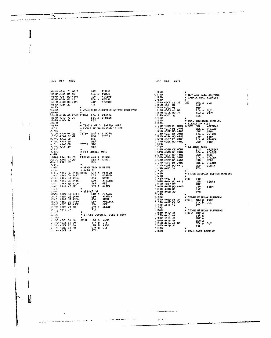
!
1-'AE 017 AOLS 49AGE Old A(.LS
j,0560 4342 7C 0015 INC ELGOF 01100)00.,
70 4385 86 FO LlA 4 #QCGO 01110 * GET A/o DATA ,OUTINE
00580 4387 8D 43YL JSR FIXEND U1120 * X-DATA REU. ADDRESS005YO 438A e6 F7 LDA A #QP0i 01130 *JX)00 4. 8C BD 43YE JsR FIXEN8 01140 43CF A6 02 GET LDA A 2.X
,0610 4,8F 3 ,HTS , 11 SO 4301 Os NOP6620* 01160 43)2 01 NIoP
0:'630 * iEAU CONFIGURATIoN $"ITCH REGISTER 01170 4303 Ad 00 LOA A O.X00,,,40 * J1130 4305 80 7F SUd A 057F00'6b0 4390 66 2800 CONRO LOA A PIAODA 01l190 4307 3V RISJ0660 43,3 1,7 2E STA A CONTEM 01200:) 0~ 4395 3V RTS 01210 * E0O ENCODERS ROUTINEJ0610 U1220 * ELEVATION AXISiO(() * TEST CtNFI1. SIT(H HORD 01230 430 CE OOBA REICS LOX tELTEMP0* C=SE" IF Sh 0,4SC,0 IF OFF 01240 43 3 6 2406 LOA A eIA2D8
.h)710 * J1250 430E BD 4403 JSR Sf88")0120 4396 94 2E TSTSW AND A CONTEM 01260 43E1 b6 2404 LOA A p'I.21A0730 4398 27 02 BEO TSTSI 01210 43E4 80 4403 JSR Sf8F:)074(j 439A 0C CLC 02PO 43F.7 F6 240; LIOA 0 PIA4VA007"U 439H 3v RT 01.90 43EA 80 440U JSR SrBFI., Oic/A 430C 0D TSTSI SEC 01300,071(. 439b 39 RT5 01310 AZIMUTH AXIS007;; * U1120 43ED CE OOBF LOX #AZTEMP)01o * FIX ENABLE WORD 0)1330 43F0 6 2409 LOA A PIA3D9oodO * 01340 43F3 80 4403 JSR sTeF.,0810 43YE 94 2D FIXEN8 ANt) A CONGO 01350 43F6 86 2408 LDA A PIA30A.0)0 43A0 87 20 STA A CONGO 01360 43F9 80 4403 JSR STBF00,1:0 43A2 39 RTS 01370 43FC 86 240C LOA A eA40A)04( * 01380 43FF 80 4412 JSR SrF 23* HEAD TRIM ROUTINE )"1390 4402 39 RTS
* AZIAUTH 01400 *)104l1I 43A3 So 241 RTRM LDA A 'IA08 01410* STORE DISPLAY BUFFER ROUTINE.': ,J3A4O CE 2417 LOX #SAD6H 11420 *
43A9 .J 43G6 JSRi SC(ON 01430 4403 16 STBF TAB)c VOG 43AC CE 241b LDX *PIA6OB 01440 4404 B0 4412 JSR SrBF2,uylO 430 ED 43CF JSR GET 01450 4407 08 INXJ.,;,J 43o2 97 2F STA A AZTM 01460 4408 BD 4401) JSR STBFI, I * 01470 4408 08 INX
& ;-C4 * ELEVATION 01480 440C 39 RTS;OvSu 4384 86 2414 LOA A PIA60A 01490 *
s,0'f) 4387 CE 2416 LOX #SADOA 01500* STORE DISPLAY BUFFER-IY'70 438A 80 43C6 JSR SCON 01510 4400 C4 OF STBFI AND 8 #-OF00910 4380 CE 2414 LDA #PIA60A 01520 440F E7 00 STA B 0,X)V9O 43C0 8D 43C0 JSR GET 31530 4411 39 RTS
jlC')O 43C3 97 30 STA A ELTRM 1540,110 43CS 39 RTS 01550 * STORE DISPLAY BUFFER-2
* 01560 4412 44 Sf8F2 LSR Ao,)l3v * STRO8E CONTROL PULSE(B REG) 01570 4413 44 LSR A1140* 01580 4414 44 LSR A0),60 43C6 C6 3e SCoN L.;kA 8 W$E 01590 4415 44 LSI A
01 6, 4J1N V/ 00 STA 8 OX 01600 4416 Ay 00 5TA A OGX,JO', 43CA Cb 30 LDA b #$36 01610 4418 39 RTS
1 ' ' ".3CC ,t7 00 5 FA 8 OX 01620 *JI .A) 43CE 39 RTS 01630 * REAU GACS ROUTINE
I-U

PAGE 019 AGLS PAGE 020 AGLS
01=40 * 02180 4472 54 LSR B0)650 4419 01 RGACS NOP 32190 4473 Dl RI CMP B Tfl01660 * ELEVATION 02200 4475 2D 09 HLI TVAL201670 441A BD 45E3 JSR RELGAC J2210 4477 2E 05 BGT T4AL401680 * AZIMUTH ,2220 4479 7D OOE6 TST TF01690 441D 86 2403 LDA A GCSAZ 02230 447C 27 02 tEG TVAL201700 4420 64 3F AND A 0$3F 02240 447E 00 TVAL4 SEC01710 4422 81 36 CMP A 0$36 02250 447F 39 RTSW)120 4424 27 01 &EQ RGACI 02260 *01730 4426 39 RTS 0;1270 4480 OC TVAL2 CLC01740 4427 B6 2401 RGACI LDA A PIAIDB 32280 4481 39 RT5u1750 442A 43 CON A J2290 *01760 4428 CE 0603 LDX #$0603 02300* READ ANALOG ERROR VOLTAGES01770 442E DF 81 STX THI 02310 *01780 4430 8D 4458 JSR TVAL 02320 4482 4F RAEV CLR A01790 4433 25 16 BCS RGAC2 02330 4483 97 3C STA A MUXADO01800 4435 97 87 STA A GACTEM t)2340 4485 C6 05 LDA B #50l)lO * 02350 4487 CE 0035 LDX #ERRBUF01820 4437 B6 2400 LDA A PIAIDA J2360 * SETUP FOR REPEATED TRY'S01830 443A 43 CON A J2370 448A 97 3E RAEV5 STA A P9REVAL01840 4438 CE 0909 LDX #$0909 02380 448C 86 05 LDA A #501850 443E DF 81 STX THI 02390 448E 97 3D STA A N'MNED01860 4440 BD 4458 JSR TVAL 02400 * LOOP ON A/D CHANNELS01870 4443 25 06 BCS RGAC2 02410 4490 86 34 RAEV2 LDA A #$340)880 4445 97 88 STA A GACTEM+I (2420 4492 a7 2412 STA A SAD5U1890 * FIX DISPLAY BUFFER 02430 4495 96 3C LDA A MUXADD01900 * ALIMUTH 02440 4497 87 2411 STA A PIA5DB01910 4447 DE.87 LDX UACTEM 02450 * 100 USEC DELAYJ1920 4449 DF 33 STX AZGCS 02460 449A 86 10 LDA A #1601930 4448 CE 009A RGAC2 LDX #AZ0CDS 02470 449C 4A RAEV4 DEC A01940 444E 96 33 LDA A AGCS 02480 449D 26 FO ONE kAEV401950 4450 OD 4403 JSR STBF 02490 44,)F R6 3C LDA A #$3CJ1960 4453 96 34 LDA A AZGCS.I 025(.00 44AI 87 2412 STA A SAD5f)1970 4455 BOD 4403 JSR srBF 02510 * WAIT EOC01980 4458 6F O0 CLR OX 02520 44A4 86 20 LDA A 032)1990 445A 39 RTS 02530 44A6 4A RAEV3 DEC A02000 * '12540 44A7 26 FD BNE REV31)2010* TEST GACS VALUES 02550 * READ AND STOW: PATA02020 * 02660 44A9 96 2410 L.A A PiA5LA32030 44B 7F 0086 TVAL CLR TF 0257(0 * TEST FOR CONSEC. READINGS02040 445E 96 TAB 02580 44AC 91 3E CM'. A- PREVAL02050 445F C4 OF AND B #SF 72590 44AL 26 LA 4NE RAEVS02060 4461 CI 09 C4, 8 00 02600 44bL, 7A 0030 DEC NUMkED32070 4463 2F 02 BLE TVAL3 02610 44b3 26 B 13NE RAEV202080) 4465 OD SEC 02020 4485 A7 00 STA A OX02090 4466 39 RTS 02630 447 08 INX02100 4467 DI 82 TVAL3 CIP 8 TLO 02640 448 96 3C LDA A MUXADO02110 4469 21- 03 BLE TVALI 02650 44dA 88 10 AXD A 0$1002120 446B 7C 0086 INC IF 02660 44BC 97 3C STA A MUXADO,2130 * 02670 448E 5A DEC 802)40 446E 16 TVALI TAB 02o80 448F 26 C9 BNE RAEV5,)2150 446F 54 LSR B 02690 44CI 7F 2411 CLR PIASDB02)60 4470 54 LSR B -)2700 44C4 39 RTS'2170 4471 54 LS 8l 02710 *
I
1KI

PAGE 021 AGLS PAGE 022 AGLS
02720 * TEST PIA8 SWITCHES (B SIDE) 03260 451B 24 OF BCC SLPOI02/30 * C SET IF Sw ONIC-O IF OFF 03270 451D CE 0300 LDX #LOAD202740 * 03280:2750 44C5 b4 241) T6TSB8 AND A PIA8DB 03290 4520 86 40 LDA A #LDP2N);)160 44CH 27 02 4E0 TST81 03300 4522 BD 4396 JSR TSTSM),710 44CA OC CLC 03310 4525 24 OF BCC SLPO3,), /40 44CB 39 RTS 03320 4527 CE 0500 LDX #LOA04
)2/'0 44CC OD TST8I SEC 03330 452A 20 OA dRA SLP03J00 44C0 39 RTS 33340 *j2110 * 03350 452C 86 40 SLP)I LDA A #1.DP2M0.2,2o * TEST PIA8 SWITCHES (A SIDE) J3160 452E SC 4396 JSR TSTSW02:330 * C SET IF S-1l (IRC-0 IF OFF 03370 4531 24 03 BCC SLP0372840 * 03380 4533 CE 0400 LDX #LOAD3J2050 44CE F4 241C TSTS8A AND A eIA8DA 03390 *).-'i(H 4401 27 02 SEQ TST82 03400 4530 0' 31 SLP03 STX ELOCSJ211/0 4433 OC CLC 03410 * FIX DISPLAY BUFFERC2b80 44D4 39 RTS J3420 4538 CE 0088 LOX #ELGCDS.)2890 4405 OD TST82 SEC 03430 4538 96 31 I.DA A ELGCS,)29')C 44D6 39 RTS 03440 453D BD 4403 JSR STBF02I1: J1450 4540 96 32 LOA A ELGCS+I92y0* SET RU FLAGS 03460 4542 BD 4403 JSR STBF)2930 .,)3470 4545 6F 00 CLR 0,x
J2940 44D7 7D 0018 SRUF TST RUCNF 03480 4547 39 RTS02V50 440A 26 IA BNE SRUF3 03490 *02960 44DC 86 10 LDA A #RUCKW 03',0002970 44DE BD 44CE JSR TSTS8A 03510 *J2990 44EI 24 03 BCC SRUFI 03520 * FIX DISABLE WOITINE32yv0 44E3 7C 001B INC RUCWF 03530 *03000 * 03t)40 4548 43 FIXUIS C(M AU3010 44E6 70 0024 SRUFI TST RUCCNF 03550 4549 9A 2D ORA A CONGO03020 44E9 26 IF BNE SRUF4 J3' 60 4548 97 2D STA A CONGOuJ3030 44EB 86 20 LOA A #RUCCWM 035 70 454D 39 RTS03040 44ED BD 44CE JSR TSTS8A 0358O *03(50 44F0 24 03 8CC SRUF2 03,90 * TEST OFFSET ERRORS03060 44F2 7C 0024 INC RUICWF 030:00 * C SET-OFFSETbALLOtWED03070 44F5 39 SRUF2 RTS 03610 * C-0 oFFSEr O1K03080 44F6 7F 0024 SRUF3 CLR RUCCWF 03620 *03090 44F9 86 20 LDA A ORUCCWM 33630 454E CE 0035 TERR LOX #ERRBUF03100 44FB 80 44CE JSR TTSSBA 03640 4551 5A DEC B03110 44FE 24 F5 8CC SRUF2 33650 4552 D7 83 STA 8 HoLDS03120 4500 7F 0018 CLR RUCOF 03660 4554 27 04 BEC TERRI03130 4503 7F 0024 CLR RUCCIF C3670 *03140 4500 7C 0024 INC RUCCNF 03680 4556 08 TEhR2 INX03150 4509 39 RTS 03690 45i7 5A DEC B03160 450A 70 0018 SRLF4 TST RUCWF 33700 45.F 26 FC BNE TERR203170 450D 27 E6 BEQ SRUF2 )3710 45'.A A6 00 TERRI I.DA A O,X031B0 450F IF 0024 CLR RUCCWF 03720 455C CE 4574 LDX #=RRVAL03190 4512 39 RTS 33130 45SF )6 83 LL7 B H,)LCa03200 ) 1.3740 4561 27 04 ))zo TERI,403210• SET LOAD POSITI(N )3750 4563 06 TEI:R3 I -X33220 •376 456. 5A JEC B03230 4513 CE 0200 SLPOS LOX *LoADI 371(; 45), 26 F5 8)I TERR3
03240 4516 86 80 LDA A OLDPIM wJJ1CO 4567 E6 00 TERH4 Lk B OX03250 4518 OD 4396 JSR TSTs J379j 4569 41) rs A
I
II
-,.I - . .... =='

1
J. 2 A3L5 J'A 14 AGLS
j jI X 4-, 0,AA (11 3PL I L:k 04 340 45135 26 06 it. L ' 17
)'l1U * ;4350 4587 86 02 LA A ',
j 3:,.0 4 ,oC 40 J- ; A U4360 4539 YA AV OFA A :1LIT
:11h (0 40o, I I Fi :lii CbA 14770 45,". V7 AV STA A =LLI I
1:140 4 )oo 2, 12 eL TERhD ,438O *
)3,'A, 41,10 OC CLC J43Y 458i CI 01 CK07 CAP Il #I
)3,46U 4111 3' ars )4400 45.BF 26 3, BN E CK08
)3 ./0 J4410 45C I ft 0I LA A 1I3 ,,U 4512 .); Ti- 16. SC )44;0 45C3 9A A9 ORA A :'1.LIT
3J3191) 4573 3y J1I 34430 41C 97 AV ST4 A ELLI r
3YO * )4440 *
j390 * 04450 45C7 7A O0bA CKO8 DEC 3 aB
!) 3, 2 4t74 E,.VAL EU * 04460 45CA 26 BD BNE CK02
9 3930, 4574 OA Fcb JP 04470 * TEST GO1/NO-GlI
-)J)40 45 / 05 t-(,3 LoC .)4480 45CC 7D 0040 TST EFLAG
1,395(; 4570 05 Fca LMP 04490 45CF 26 09 81E CIII
)3960 4-77 05 FcO EAC 04500 * ENAdLE GO
uj97(: 457t, l FCr3 EPA 04t10 4501 (86 36 LDA A #S36
.:3V;o * 04520 45D3 87 241F STA A LAMP
039 90 • C)'1CK OIFSFT% AND CoI7TNI)L 01O/NO-01O j4S30 4506 7C 0027 INC CKOF
J4(100 * 34540 4509 3V RTSJ,)10 .57Y 7-F 0027 CKC crH C<oF 04550 * ENABLE NO-Go)4070 457C C6 0I .rk 8 ", 04560 45DA 86 3E CKI LDA A #s3E
J1030 -,t 7h 17 4A STA 8 SAVU 04570 45UC 87 241F STA A LAMP<4L40 412(0 1 0040 C.. uFLAU 04580 450F 7C 0027 INC CKOF
)4050 450'3 7F 0o1A CL AZLIT 04590 45E2 39 RTSJ4,060 4tl 7F 0WAY ClI ELIT 04o00 *,4o70 4t.0y 06 3A CK02 I.IIA H1 SAVt 04610 * READ ELEVATIONI GACS
)40:0 * CALL TE3T ER.OR 04620 *
J4090 45d8 6D 454E JSR TERR 04630 45E3 86 2402 RELGAC LDA 4 GCSEL
)41( W * SETUP ERri()R I A)D FOli DISPLAY 04640 456 84 3F AND A #S3F
)411(; 45Z3E 24 37 1CC CKo8 04650 45E8 81 36 CIMP A #S36
;412, 45U 7C 0040 1[Nc EFLAG 04660 45EA 27 01 8EU RELI
)4130 * 14670 45EC 39 RTS
0.140 4593 06 eA LDA 93 SkVb 04680 * READ GACS).150 4t,5 CI O5 C'I, 8 &3 04690 45ED 86 2401 RELI LDA A P[AIUB
)4160 41-07 26 96 NE C<04 04700 45F0 43 COM A34170 45V9 t,6 04 LDA A 04 04710 45FI CE 0103 LDX #50103
)4110 45YE 9A AA (;!.A k ALLIT 04720 45F4 IF 81 STX '1Hl
)4190 4590 97 AA STA A AZLIT 34730 45F6 BD 4458 JSR TVAL
.4)00 * 04740 45F9 25 16 8CS REL2
04210 450)- C 04 CK0* CMI- H *4 04750 45FO 97 87 STA A GACTEMJ4/,2U 45AI 2b )6 8 N CKII 04760
04230 45A3 86 02 I.'A A 02 04770 45FD 86 2400 LOA A eIAIDA(4240 45A5 94 AA , ()hA A AZLI r 04780 4600 43 C0o- A)4150 45A7 97 AA STA A A.ILIT 04790 4601 CE 0909 LDX #$0909
:425J • 04800 4604 OF 81 STX Trl
.:,_70 4tAV CI 03 CKII C4P 8 #3 04810 4606 SD 4458 JSR TVAL
042M0 45Ao 26 06 3):5 C06 14820 4609 25 06 a8CS REL2.)14)9 454,) .36 01 L.)A A #1 04630 4608 97 88 STA A GACTEM*I
04300 45AF A AA )liA A A!L lr4840 * FIX DISPLAY BUFFER
)4410 45o1 97 WA 9TA A A/.LIT 04850 4600D DE 87 LDX GACTEM.)4320 * 04(60 460F OF 31 STX ELOCS I04330 4,:43 1:1 J2 CKO0 0.4' 8 7 04870 4611 CE 0088 REL2 LOX .ELGCDs
IIIUI
, l ,-- ,, ..., , i , -

PAGE 025 AGLS'AGE 026 AULS
04880 4614 96 31 LDA A ELGCS04890 4616 BD 4403 JSR s reF )542u 4659 4F CLR A04900 4619 96 32 LDA A ELGCS.I ')5430 465A Do 21- LDA 8 AZTRM04910 4618 BD 4403 JSR STBF )5440 465C 2A (4 8eL C')PAZI04920 461E 6F 00 CLR O.X U,450 465E 7C 0026 INC SIG04Y30 4620 39 RTS )5460 4661 50 NEG B(4940 • )t470 4e62 01 CO'AZI NO',)4950 * TEST AZ ERR RANUE 'J480 4633 01 No)v04960 * (D/A F)RMAT) ()t490 4664 ,0 476E JSI? BINICDJ4970 3 3550, * ADD TRIM T) ENCODER READING04980 4621 DE 53 TAZERR LOX AZERR 05510 4667 CE 00180 LOX #TEMBCD04990 4623 C6 01 LOA B OAZLIM 05520 466A OF 62 SfX Al05000 4625 BD 4631 JSR TSTIT 05530 4o6C CE 0081- LDX *AZTEMP05010 4628 39 RTS 0t540 466F DF 64 STX A21,)2(J J5550 4671 CE 00),9 LDX #RESULT 4
05030 * rEST EL ERR RANGE 05560 4674 8D 47FE JSR BCUALID0504U * t15510 * ADJUSr FoiR R LLOVERJ0550 462Y E 15 TELERd LDX ELERR U5580 4,77 CE 009F LOX #AZDISP05060 462b C6 01 LDA B OELLIM 05590 407A 8D 48A3 JSR ADJ.Jt;7(;
462D [0 4631 JSR T3TIT J15600 * SUBTRACT RESULT FROM GACS
)5(00 4630 39 RTS J561C *J2)090 * J562C 407D CE OOvF LUX #AZDISP,) )( * 05630 4080 OF 68 STX S2,5110* TESr 0/A F()RMAT 35640 4682 CE 009A LDX #AZGCDS05120 * 05650 4685 OF 66 STX SI05j 130 4631 OF 89 TSTIT STX SAVA 05060 4687 CE 0085 LDX 0.4ESULr'(1.J4(0 * FIX FOR SIGN 05670 468A B 4855 JSR HCDSU8.)150 4633 7D 0089 TST SAVA 0)5680 * ADJUST FOR ROLLOVERJ'LjU 4636 2A 06 , PL TST13 05690 469D CF 00A4 LOX #AZERD05170 4038 90 89 LOA A SAVA J5700 4690 0) 48A3 JSR A.)J051HO 463A 84 7F AND A #S7F )5712) * FIX FoIl + )R3 - 32000)90IU 463C 97 89 STA 4 SAVA 05720 4693 7F 0026 CLR SIG0-,('0 * J5730 4690 CE OOA4 LDX OAZERD
E) 463 96 89 TSI13 LDA A SAVA ).)140 4099 bD 48CD JSR TEST320- 404(j b4 OF AND A #$F i5750 46,'C 24 IF 8CC C21PAZ3)0 3(0 4642 27 02 8E0) TSTII 05760 F-IX IF ' 32000:)5,4(; 4044 OD SEC J5770 469E CE O)A4 LDX #AZERD,5250 4645 3V RTS ,)57t0 46AI OF 62 STX Al
*2, * CHECK LSb J5790 46A3 BD 4700 JSR NINCOM)5270 4c46 96 8A TSTII LOA A SAVO 0,300 46A6 CE 46DA LDX #CoNST25.2 4c,48 II CBA U58110 46AY DF 64 STX A2
-9; 4e,49 01 NOP 058120 40AB CE 0089 LDX #RESULT+4D'J3(L 404A 22 02 SHI TSTI2 05830 46AE BU0 47FE JSR BCDADDC? , 10 464C OC CLC 05940 •230 4(4f; 39 RTS 05350 4661 CE 0OA4 LOX #AZERD
il 30 4(;4E OL) TST12 SEC JJ60 4614 HD 4902 JSR XFER',140 404F 39 RiTS 053 70 *,* ,058810 4687 7F 0026 CLR SIG,,t,0 * C,) eUTE AZ ERROR 05390 468A 7C 0026 INC bIG
05900 * TEST .2AGNITUE (IF DISPLAY VALUE, o3f 0 4( :J 7- 0026 CO()PAZ CLR SIt 05910 468C CE 00A4 COPAZ3 LDX PAZERE!),, 9(2 .1(,b53 7r ()J2C -LR OISAZ 05920 4oCO 80 480F JSR TESTN254 42 46)0 ;Ct O)IO LDX rE.43CD 05930 * FIX SIUN OF DISPLAY2541, * CONVFRT T3IM T) BCD J5940 46CJ 16 02 LOA A 02
)5950 46C5 71 0026 TST SIG
1.
!i

,-'A :[ 0. 7 A;L'; PAGE 028 AQLS
h,960() 46CB 21 02 BE) C,)PAZ2 06420 * FIX FOR + OR - 32000)5970 46CA 86 01 LOA A #1 06430 4127 7F 0026 CLR SIGJb80 46C7 A 4 60LA A AI 06440 472A CE 0095 LUX #ELERD05)1O 40CC 97 A4 C EPAZ2 STA A AZERO 06450 472D 2D 48CD JSR TEST32,)5990 * CONVE~E ERRol) T( BINARY 06460 4730 24 IF 8CC CoPEL3Jo )O0 40CE CE OXA4 LDX #AZERD 06470 * FIX IF • 32000.)(,CIO 4601 BU 4910 JSR BCDBIN 0480 4732 CE 0095 LDX *ELERDJ6020 4604 ,- 53 STX AZERR 06490 4735 IF 62 STX Al06030 46D6 7C 002C INC DISAZ 165(00 4737 BD 47D0 JSR NINCOM36040 46J9 39 tTS 06510 473A CE 460A LjX #C(INST06050 46,A 06 CoNST FCB 6,4,0,0.0 00520 473D IF 64 STX A24
60b 04 06530 473F CE 0OB LDX #:?ESULT+446DC 00 06540 4742 BD 47FE JSR BCDADD46D0 00 06550 *46DE 00 )6560 4745 CE 0095 LOX #*[.ERD
06060 460F 03 CoNST2 FC6 3,6.0.0.0 06570 4748 8D 4902 JSR XFER46E0 06 06580 *40r1 00 06590 4748 7F 0020 CLR SIG46E2 00 06500 474E 7C 0026 INC SIG402E3 00 *0610 * TEST MAGNITUDE (F DISPLAY VALUE
06070 06620 4751 CE 0095 C(IPEL3 LDX #ELERD06080 COMPUTE ELEVATION ERROR 06030 4754 BD 48DF JSR TESTM06090 4 36640 * FIX SIG,4 OF DISPLAY06100 461:4 7F 0026 COPEL CLR SIG ..650 4757 86 02 LOA A #23)o110 46E7 7F 0028 CLR DISEL 06660 4759 7D 0026 TST 51606120 46EA CE OOO LOX #TEMBCD 06670 475C 27 02 iEo CuPEL2Jo130 * CONVERT rRIM TO BCD 00680 475E 80 01 1uk k *I06140 46ED 4F CLR A)6150 46Ek D6 30 LOA B ELTt]A 06690 4760 97 95 CoPFL2 STA A ELED)(.160 46F0 2A 04 RPL COPELI 00(00 * C(ONVERT ERRO)R TO BINARYJ6170 46F2 7C 0026 INC SIG 06710 4762 CE 0095 LDX *iLERD,)6180 46F2 5 6 NEG B SJ6720 4765 80 491L JSR HCD)BIN)e(190 46F6 01 C(PELI NOP 07.30 '1768 F 55 :;IX ELERR3.200 46F7 01 NOP 16740 476A 7C 0028 INC ISEL
36004o70)NIP1 O0 476,0 3V RTSJ6210 46F8 BD 476E JSR BINBCO .10760 *
00220 * ADD TRIM TO E RCOER hEADING )6770 B BINARY-BCD COIVERSIONJ06230 46FB CE 000 LDX #TE.BCD 06710 * X-AUDRELS OF ?ESULT(5)06240 46FE OF 62 STX Al 06190 * A,4= HINA-?Y VkLUE06250 4700 CE OOBA LOX *ELTEMP )6OOOo60 4703 OF 64 STX A2 .j6f3l1 476E OF 70 INBCD STX HbOLDX06270 4705 CE 0089 LDX #RESULT 4 06820 4770 OF 6E STX oUTX(6200 4708 8D 47FE JSR BCDADD06290 * ADJUSr FOR ROLLOVER06300 4708 CE 0090 LDX *ELDISP (6840 4774 IIE 62 ST( Al06310 470E BD 48A3 JSR ADJ 06d50 406320 * SUBTRACT RESULT FROM GACS 06860 4776 CE 2710 LX #10(10006330 4711 CE 0090 LDX *ELDISP )68r0 477C CE 03 LOX T100006340 4714 OF 68 STX S2 ,6)P 477F 8I03 4741: LS lIZ06350 4716 CE 0088 LDX #ELOCDS 16900 4712 CE 0061 LOX #10006360 4719 IF 66 STX SI 0691( 4785 HD 47AF iSP HZ06370 4718 CE 0085 LDX #RESULT )6,2?( 4738 CF OO0A LOX #1006380 471E 8D 4855 JSR BCDSUB :,mv330 478P. 0 47AF JS:? fIZ06390 * ADJUST FOR ROLLOVER fV,,,40 47'4F 0F f+ LOX oUTX06400 4721 CE 0095 LDX OELERD 950 47,)0 F7 X) iTA B O,X06410 4724 8D 48A3 JSR ADJ
I
~1

,'';F: '.r A;L PA F 030 AULS
, 09 * ESt 7,,IGN FLA 07500 47EI 4F CLR A6;bCO 4195 ,0 0070 TST ')I0 07510 47EB 0D SEC)6990 419b 20 01 ,3V 1161 07520*7,990 41r7 3F ETS R67530 47E9 AV 00 NIN2 ADC A O.Xd/U )0 * C~rI EMENT RESULT (M7 64000) 07040 47EH HD 4848 JSR JOCK10 47, 0I lO '1 NI VX HOLUX ) 15,0 47u 84 OF AND A #$FA.'C 4iVA Hl) 471,) JSR NINComi 07O,60 47F0 A7 00 STA A O,X'JA Ii 4 IYL Ct' 461,A LiJ #CONST " /t.70J1'4/ ' 4, A, Lv" 04 srx A2 370PO 47F2 86 00 LDA A #31i)50 4 /A, ,l" : H1)B LDX #RESULT*4 u7590 47F4 09 DEXi 47A5 7. 4?F JSR HCDADD 0/600 47F5 5A DEC B4lA 74 LDX boRX J10O 47F6 26 Fl BNE NIN2S I 4'2 js XFER 076?0 47F8 39 RTSR." ,, 01630 itT O7040
* FIX X REU. POINTER*II: TEST NU4,IER oF TIMES VALUE DIVISIRLE 07650I*Jk, 414, 1* Q TIZ STX IZX )7060 47F' 08 FIXX INX'4( 4 h/, :. 1)7E CL CNX 07670 47FA 'A DEC 80) 413 9 1 7 TIZ2 STA A CN DAX U0/080 47FB 26 FC 8NE FIXX' , I 17 H) STA A OLDBX 07690 47F0 39 RTS* TW'AL S'JTA 07700* TIAL S'BTRAlCT u7710 * ADD 2-5 DIGIT BCD VALUESI, 4'/, , 73 SUB 3 ]IlX+l 07720 * AIwAODRESS OF VALUE I MSB4/I ,y 4 2 72 sac A TIZX 07730 t A2-AD)RESS OF VALUE 2 MSB
' b, 10 lOS TIZI 07740 * X-ADDRESS OF RESULT.7,o 2, 0'OE INC CX 07750*7 F9 A dRA TZ2 3)7760 47FE OF 76 BCDAOD STX ADOXI41* FAIL SUBTRACT 07770 4800 7F 0026 CLR 5IG-. 41 E tI:4o ITX T O'T80 * FIX Al, 47A4 0 LCAA 09X 07790 4803 DE 62 LOX Al7' 4. 0.7 0 STA A 0.X 07800 4805 C6 04 LDA B 04/ 4/8 7) r, X 07810 4807 BD 47F9 JSR FIXX47' 9 r 'E ST) 7UTX 07820 480A OF 62 STX Al7 4 0 / 71' LDA A (LDAX 07830 * FIX A27i 41 0 '0 LOA B OLDBX 07840 480C DE 64 LDX A2l ), RTS 07950 480E C6 04 LDA 8 #4* 07860 4810 80 47F9 JSR FIXX7'4O * NINES COMPLEMENT 5 DIGIT BCD 0 07870 4813 OF 64 STX A214,; * X= ADDRESS OF BCD MSB(BEFORE AND AFTER) 07880 4815 OCJ/3',0 itCLC4 J0 C 07890 * GET FIRST VALUE!"I 47A( CO 04 1'INCO;M LDA B #4 07900 4816 C6 04 LDA B #4J40 Bj 47Fy JSR FISK 07910 4818 DE 62 BCAI LOX Al(i 47)5 0" 84 STX KEEP 07920 481A A6 00 LDA A OX17390 * COMPLEMENT EACH DIGIT 07930 481C 09 DEX1/4')( 4707 C6 05 LDA B 0 4
14'10 47.)Y 86 0y INI LDA A #09 01940 48A0 OF 62 srx Ait4 47 j AO 00 SUB A O.X 07950 * ADD SECOND.7<40 471)j: A7 00 STA A OX 07960 481F DE 64 LDX A2)'. 4 41.1 00 DEX 07970 4821 A9 00 ADC A OX)/4, 4/0 AO DEC B 07980 4823 BD 4848 JSR JOCK14: 1 4/t 1 20 F6 BNE NINI 07990 4826 09 DEXi, 70 ADD ONE To RESULT 08000 4827 OF 64 STX A2A4D) 4Di- E A 4 LOX KEEP 08010 * STORE IN OUTUT1/4,1(, 4/ 1 0J LOX C 05
08020 4829 DE 76 LDX ADDXI1DA B #5 08030 4828 A7 00 STA A O.
I

PAGE C'31 AJLS eAOE ('32 AJL,
08040 412D 04 DEX 0S5HU 4U78 CE 0OA8 LJX #TE,'M3IJBJ8050 482E DF 76 STX Ar)DX I J85YO 487b 8J 4116 JS;4 C.)MI64J8060(X) * ADD hINUFlD AIl FIX 51N OF RESULT08070 4H30 5A DEC . 00d610 487E bE 66 LOX SI08(080 4H31 26 E5 8NE hCAI 01620 4178) Li- .2 STX AlJY.090 48133 DE 62 LDX Al )Fo30 48,32 CE (')AII I.'X 'TE "0U,,1810,I 4H35 A 6 00 LDA A OX H,1540 48615 DF 64 iTX A,381110 4137 0'- 64 LDX A2 1365) 41H7 DE 7f? LOX 5OJ3XI)8 12) 439 AY 00 Ac A OX .,,60 469 83 4 7FE JSR I ' 'DAJD)11I3u 4 83v H' 4848 JSp JOIC.K )670 4H8C 39 RISi11 41") 413f 24 03 8CC H'A2 18690 *)H150 4F40 7C 002b INC 5IG 11,0b690 64'S CIIMPLEME4T EI)I[TINE0 1t ) 4143 DE 76 ECA2 LDX ADDXI 08I1O *H11170 4845 A? 00 STA A U.X 08710 4 VBD OF 62 C0IIXP,4 STX AI081aC 4847 39 RTS J8720 488F b .2 4700 JSR l1,JI C IAJ8190 484b 01 JoCK NOP 3E730 48v2 CE 46bA LDX #:OINSTU820U 4R49 81 09 CMIP A 09 )8740 48'5 OF 64 STX A?0;210 4846 2E 02 BGT JOCKI 08750 48V7 CE 008V LO)X #9ESULT+4,)8220 484
r OC CLC 00 760 48'A BD 47FH JsF, B(DA Dr
08230 484E 3Y RTS cd 770 489U) L: 62 LO Al0U1240 484F 88 06 J()CKI A D A #6 ')1711 48YF ,90 4902 JR XFER08250 4851 84 OF AND A #SF OP9790 461A2 39 -TSJ2O 4863 01 SEC '), 0 *J8270 4854 39 RTS o81110 *,.2Po * W0320 * ADJUST FiR > 99Y99 & > 64000 PILLOVclF082Q0 * SUBTRACT 2-5 DIGIT BCD VALUES 08630 *01300 * SI-ADDRESS OF MINUENJ 08240 4FA3 OF C4 ADJ srx Ai)JX110310 * 52=ADDtESS (F SUBTRAHEND 'ORP850 4FA5 711 0026 TST 1G)8320 * X-ADDRESS )F RESULT 08d60 413A8 26 081 INE AJJIJ8330 * 13870 * TE3T * 6400008340 4F55 LD 73 BCDSUb SEX SUBX| J83110 48AA CP 0Ob5 LOX #4ESULT0.350 4857 DE- 7A STX SUBX2 i,13v 48AD BD 48FO 3S TEST64)8360 * FIX SUbXI 18900 4810 24 15 uCC A)J2
')8370 4P'5V C6 04 LOA B 94 08910 * FIX > 64000 kOLLoVER383810 4L58 KJ 47F9 JSR FIXX J8, 20 48d2 CE 0085 ADJI LDX #:IESULT)'33Y30 4fE 01- 78 STX SUBXI ,)830 4335 DF 62 STX Al31H401 * COIMPLEMENT SU3TRAIAND 08940 48B7 CE 40DF LUX #CI(NST203410 * TRAASFER iUHTRAIAND )18950 488A DF 64 STX A208420 4,60 CE OOAd LOX vr9IISUB 08960 48dC DE C4 LDX AUJX:)8430 4;03 DI- 7C STX TX J3910 48BE C6 04 LOA 6 #4)440 46t6 CO 05 LLA 8 95 989140 48Cn 8D 47Fv JSR F IXXh84'1, 4867 CE 68 TXI LDX 52 08990 48C3 BL) 47FE JSR dCDADD,J8460 4869 A0 00 LDA A OX '1)(000 48C6 39 R[SW.3470 4f061 08 INX ()1.I * FIX ' 64000 VALUE)C49lO 4RoC OF 61 STX S2 J902U 4EC7 DE C4 ADJ2 LDX AJJX9549)O )90301 48C9 BC, 4Y02 JS R XI'E,8500 486b DE 7C LDX I X .1040 48W0 39 PTSJ8'510 4P170 A7 00 STA A OX uv15o *J0b2,; 4b7? 081 INX "voem)* TEST IF tlCD A flAY ) = 32000 (C SET IF rmtu))5:i ) 4173 OF 7C STX [1X 3v901 *3bt40 * )1900 4tCU A6 01 TLST32 LOA A OX,8050 4f,P 5A DEC B )Y109) 48C= 8I (13 Cl', A #318560 4876 26 EF NE TX! 0,;l'X. 4f)lI 2U OA lbLT T321J3t,3/0 *v ll, 4HD-i 2E Oo HGT T322
-II
N!
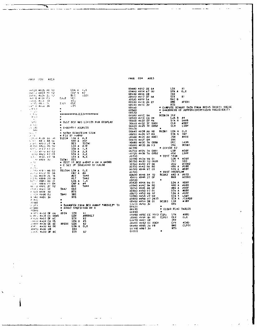
'A(h 033 AGLS PAGE 034 AGLS
-1I20 4b,5 A6~ 01 LA A IX 00480 4912 DE 6A LDX XI
l J 48D7 8)1 2 cA, P A I,2 00490 4914 A7 00 STA A OX
1i4,, 4b), 2., 1' BLI 1321 00500 4916 08 INX
)1-0 4t', o:) rJ 2 5EC 00510 4917 OF 6A STX XI4h.11 39 kT, 00520 4919 5A DEC e
,I / 46.)l, 0, 1 C00530 4YIA 26 EF SNE XFERI.rt 21 4C.). 3l CIC 00540 49IC 39 RTS
1 1i ) * 00550 * COMPUTE BINARY DATA FROM BCD(5 DIGIT) VALUE00560 * X-ADDRESS OF iUFFER(ENTRY)ID/A VALUE(EXIT)
:)i *********ALS********* 00570 ** 00580 491C 08 BCDIIN INX
0 00590 491E C6 04 LOA B #4* TEST BC RAG LIRITS FOR DISPLAY 0')600 4920 D7 SA SfA B SAVB
• 30610 4922 7F 0001 CLR MSBY* F ADDRES 00620 4Y25 7F 0002 CLR LSBY
,'I * X=BuFFEl AD0RESS 00630 *
* SETUP DIRECTION SIGN 00640 4928 A6 00 BCDBI LDA A O.X
,, * FIX I 9999 00650 4v2A 97 03 STA A TMP
4,1,F A6 A10 TESIM LDA A OX 00660 492C BD 4BEI JSR AIOX
I 4e-I 84 (t A14D A fSF 00670 492F 08 INX
I-: 4e-3 27 ()A BEO ISTAI 00680 4930 7A 008A DEC 5AVB
K,I( 4,F_1 P6 6, LDA A #39 00690 4933 26 F3 BNE BCDBI
! I.' J, L7 AlJl I STA A I.X 00700 * DIVIDE X2
'!O 4'0-: A? 02 STA A 2.X 00710 4935 74 0001 LSR MSBY1 ,u 4btb A7 03 STA A 3.X 00720 493b 76 0002 R()R LSBY
'L' 4t-EL', A7 14 STA A 4.X 00730 * TEST SIGN
48-FF 3v TSTMI RTS '00740 493o1 96 01 LOA A m5BY
* TEST IF BCD A4RAY > OR = 64000 00750 493D 710 0026 ISr S1
, * C SE] IF TRUEIC-O IF FALSE 30760 4940 27 04 3E, ACDB2* 00770 4942 8A 80 ORA A #SBO
0, , AO 00 TE0T64 LOA A OX 00780 4944 97 01 STA A MSBY4,1r2 81 06 CM A 06 00790 * TEST OVERFLOW
L 4bF4 2 )A CGT T41 00800 4946 84 70 BCD02 AND A #$70-48F6 201 6 OLT T642 )01310 4948 27 OF BEO BCDB3
48FH A6 I LDA A I,X 0OP20 2O48FA IH 04 CMP A #4 00830 494A 96 01 LOA A MSBY
U U 4,HFC 2C 02 BGE T641 00940 494C 84 so AND A 0$80
41)PE DC T642 CLC 10350 494E BA OF ORA A $OF
3,(.) 4bFF 39 RTS 00360 4950 97 01 STA A MSBY
131 4VO0 OU T641 SEC 00B70 4952 86 FF LDA A *SFFK 4U 490) 3V RTS 00880 4954 97 02 STA A LSBY
'1" 00390 4956 iH7 24D STA A PIARDB
(1160 * OO0O0 4959 DE 01 BCDB3 .OX ASBY
r"'j L) * TRANSFER FROM BCD ARRAY NRESULT" TO J;)vlo 49 5b 39 RTS
J)380 * ARRAY SPECIFIED BY X 00920 C10 3'J
00930 ItCLEAR FLAG TABLES
SI r,-'; 4,02 DIF 6A XFER STX Xl 00940 *
0,4), 4V.)4 CE 0085 LOX 5RESULT 00950 495C CE 0013 CLFU LOX #8EG
;,(j 4901 OF 6C STX X2 O960 49'5F 6F 00 CLFGI CLR O.X
')41 ) 4v09 C6 05 LDA 8 #5 0J970 4961 Oe INX
,'440 4931b DE 6C XFERI LDX X2 009,O 4962 6C 00C9 CPX #ENU)(,4', , 4900 A6 00 LDA A O.X 00990 4965 26 F8 BNE CLFGI
j04A0 4,OF 08 INX 0l)00 4967 39 RTS).,4 R, 4910 LF 6C STX X2 01010 *

-A ;E 013' AOLS FAGE 036 AuLS
01020 * INITIAL eIAS ?0IJTINE 01560 4901 7F 2413 CL? l-A5Cd
01030 0170 4904 IF 2410 CLr I [Ab5 A
01040 4968 PIAS EQU * 1680 4907 86 FF LilA A #SFF
I05C * Pik 0 (A)-SA INPUTS 015,0 4r09 07 2411 STA A v[IASM.
0l0 O 4968 7F 2H02 CLR PIAOCA )1o00 49;,C 86 3C LLOA A #s3C
01070 4968 7F 2800 CLR PIAOOA )1610 49DE B7 2412 STA A PIA6CA
01080 496E 86 3E LDA A #$3E .)1620 49t4I 86 34 I.DA A #S34
)1090 4910 b7 2802 STA A PIAOCA J1630 49F3 87 2413 STA A P1A5CS
01100 4973 86 3E LDA A #S3E J1640 *
J)110 4975 87 21;02 STA A PIAOCA 01650 * elk u -TRIM A/D
11120 * Plk 0 (3)-PRG CLOCK 31660 49E6 86 31. LDA A #$36
01130 4978 7F 28;03 CLR PIAOCB 01670 49E8 CE 2414 LDX #OiIA6t'A
)1140 478 86 FF LDA A #$FF 01680 49E8 B0 4A29 JSR SETUP
31150 4971) 87 2801 STA A P[AODB 01690
01160 4930 86 2C LDA A #$2C 31700 PIA 7 -0/A
)1110 4YH2 87 2803 STA 4 PIAOCB 01710 49EE IF 241A CLR PIA7CA
01180 4985 86 OA LDA A #10 01720 49FI 7F 2418 CLR 8iATCB
)1190 4987 87 2801 STA A PIAOOB 01730 4VF4 86 FF LDA 4 #SFF
01200 498A B6 2801 LDA A PIAODB 01740 4916 87 2418 STA A PIA7DA
01210 498D 86 20 LDA A #S2D 01750 49FV B7 2419 STA A PI'ATOB
,1220 498F B7 2803 STA A PIAOCB 01760 49FC 86 3E LDA A #$3E
01230 4992 OF SEI 01770 49FE 87 241A STA A PIA7CA
01240 4993 0 N(OP 017RO 4AOI 87 2418 STA A PIA7C8
01250 * I-IA I -GACS INPUT 01790 *
31260 4994 86 3E LDA A #$3E 01800 PiA 8 -DISPLAY
J1270 4996 CE 2400 LDX #PIAIDA 31810 4A04 7F 241E CLR PIA8CA
01280 4999 BD 4A29 JSR SETUP 01820 4A07 7F 241F CLR P)ABCB
01290 * PIA 2 -ELEVATION ENC)DER 011330 4AOA 86 OF LDA A *$F
31300 499C e6 3E LDA A $3E 01840 4AOC 87 241C STA A PIABDA
01310 499E CE 2404 LDX OPIA2DA 01S50 4AOF 86 IF LDA A u$F
01320 49A1 8D 4429 JS SETUP 01360 4AIl 87 2410 STA A P1A8D
31330 * PIA3 -AZIMUH ENCODER 31870 4A14 86 3E LDA A #$3E
01340 49A4 86 3E LOA A #$3E 01880 4A16 B7 241E STA A PIA8CA
01350 49A6 CE 2408 LDX #PIA3DA 01890 4AI9 8 3E LDA A #S3E
013,0 49A9 BD 4A29 JSR SETUP 01900 4AIB B7 241F STA A PIA8C8
)1370 *01910W1380 * PIA 4 -EL AND AZ ENCODER 01920 * ACIA SETUP
01390 49AC IF 240E CLR PIA4CA 01930 4AIE 86 03 LDA A #3
01400 49AF 7F 240C CLR eIA4DA 01940 4A20 R7 3002 STA A AC2C
01410 4962 86 3E LDA A #$3E 01950 4A23 BD 4819 IS DISXNT
01420 4984 E7 240E STA A PIA4CA OI160 4A26 O NIP
01430 * PIA 4 -ENABLES 01970 4A27 01 NOP
01440 4YB7 86 04 LOA A #4 01980 4A28 39 RTS
01450 4989 37 240F STA A PIA4CB 0I0 S
01400 49C 86 FF LUA A #SFF 02000 SETUP PIA USING X AND A REG.
01470 4VBE 87 240C STA A P1A4D 02010 *
014S0 49CI 7F 240F CLR PIA4CB 02020 4A29 6F 02 SETUP CLR 2,X
J1490 49C4 86 FF LUA A #SFF 02030 4A2B 6F 03 CLR 3.X
)I00 49CO 87 240D STA A VIA4DB 02040 4A2D 6F 00 CLH OX
J1510 49C 86 04 L0A A #4 02050 4A2F 6F 01 CLH IX
U1520 49C8 87 2401 STA A PA4CB 02060 4A31 A7 02 STA A 2,X
31530 02070 4A33 A7 03 STA A 3.X
3,340 V .'IA 5 -MUX A/J 02080 4A35 39 RTS
*)1550 49CE IF 2412 CLR VIASCA 02090
t_

PAGE 037 AGLS PAGE 038 ALS
021* INTERRUPT SERVICE ROUTINE 02040 * SERVICE OUTSIJE LXP02110 02650 4A9C CE 00C8 ISER5 LDX 020002120 TEST CLOCK 02660 4A,)F OF 08 STX TIM2U212030 7 0 TST K 02670 4AAI 7C 0007 INC TF202130 4A39 7 2803 ISEP TST PIAOC8 02680 * UPDATE DISPLAY02140 4A39 2A 6C 3'L ISER6 02690 4AA4 80 4856 Js U.)IS()21,0 4A36 B6 2801 LDA A PIAODB 02700 * TEST CRT02160 4A3E 37 2801 STA A PIAOD8 02710 4AA7 70 3002 ISER6 TST AC2S021/u * SCAN CLOCKS 02720 4AAA 28 01 BMI 1SER16),1190 4A41 CE 0004 LDX 0 3;,ATB 02730 4AAC 3b RTI)2190 4A44 Co 05 [.:-A 8 #5 02740 * TEST RECV. INT.32,00 4A46 BiJ 4COA JSR SCAT 02750 4AAD OD 4C33 ISER16 JSR All
I * TEST INSIDE LO()P(20 USEC) 02760 4A-O 25 2E BCS ISER170,).20 4A49 7M9 0004 TST TFI 02770 * 7',2230 4A4C 27 '01 8EG ISER2 *327'30 4AB2 81 44 CMP A ORD
)2EVIE4A4N 3S TI L)2790 4A84 26 OE BNE ISER9* SERVICE INSIDE L(OP 02300 4A86 CE 008B LOX #ELGCDSI22e(' 4A4.$ CE 0014 ISEu2 LOX #0 02810 4A99 OF 48 STX PTR
)2.'0 4A52 'F 05 STX TIMI 02820 4AB CE OOAB LOX #AZLIT I1'2 i0 4At4 7C 0004 INC TFI 02830 4A3E OF 4A STX PTE. * D/A READY? 02840 4ACO 86 05 LDA A #i
0.' 3 ) 4A-,JI BL) 4822 JSR DkoUT 02850 4AC2 20 I1 BRA ISERIO231 ) * TEST XENON ON 12860 * F3,0 4AtA 96 40 LOA A #XRECM( 02870 4AC4 81 46 ISER9 CMP A #IF
21 3, 4A5C BD 44C5 JSR TSTS8B 02870 4AC6 27 6 ISER0 C A II),'340 4AOF 24 ID dCC ISER7 02H90 4AC8 38 RTI02 * START DROPOUT CLOCK 0290 4ACC 38 RI0 2360 4A ,I 1F 00310 CLRl TFS 02900 4ACV CE 0013 1SEP11 LOX IBEG02360 4864 CF 03E8 LOX #1100 02910 4ACC OF 48 STX PrR23.10 4A64 CF 0E STX TI"35 02920 4ACE CE 0020 LOX #DISAZ+I, .404A01 OF8 I I STX TIMS 02930 440) DF 4A STX PTE'J,'3, 0 4A09 7C 0010 INC TF5 02940 4438 Cl LD A E)2, .)u * TEST ON FOR 25 TIMES 02940 4AD3 86 01 LTA A #1
0)241 4A6C 7C 004E INC X()N 02950 4AL7 97 4C ISERIO STA A SPC,)40 AF 64 LAA (N02960 4AD7 97 4D STA A ASP)2420 4A6F 96 4E LDA A XON 02970 * OUTPUT CR/LF)2430 4A71 31 19 CP A #25 02980 4AL9 BD 4C51 JSR CRLF)2440 4473 20 14 BLT ISERB(2990 * INH REC/ENB XMIT2460 03000 4ADC 8D 4813 JSR DISREC,2460 4A75 7A 004E DEC XON 03010 4AOF 38 RTI)2470 4A78 7F 0017 CLR XRECF 03020 *024t0 4A78 7C 0017 INC XRECF 03030 TEST XMIT. INT.)2490 * TEST TIMEOUT AFTER OFF 03040 4AEO B6 3002 ISER17 LDA A AC2S)2',0 4A7E 7F 004E ISER7 CLR XON 03050 4AE3 85 02 BIT A $2)2,"-10 4A81 70 0010 TST TF5 03060 4AE5 26 04 ANE ISER12)2120 4A84 26 03 BNE ISER8 03070 4485 26 0 E SE2253(0 4A86 7F 0017 CLR XRECF 03070 44E7 86 3003 LOA A A.2R
03080 4AEA 38 RTI3250 8 TEST LEAPON SO 03090 * CHECK SPACE COIUNT)2t>'A 4AH9 86 80 ISERS LOA A #PNM 03100 4AE8 7D 004D ISER12 TST ASP)25, ) 4AHB BD 44CE JSR TSTS8A 03110 4AEE 26 08 BNE ISER132570 4A8E 24 06 8CC ISER4 03120 4AFO 96 4C LDA A SPC, 033iO 4A90 7F 0016 CLR wPNF 03130 4AF2 97 4D STA A ASP
'10 4f 3 7C 0016 INC LPNF 03140 4AF4 86 20 LDA A #$20* OUTSIDE LOOP '3150 4AF6 20 13 BRA ISER14
)21.10 4iS6 71, 0007 ISEk4 TST TF2 03160 * PROCESS CHAR12',20 4899 27 O BEO ISER5 03170 4AF8 7A 004D ISER13 DEC A3P'2e, ,J 4A9 38 RTI
III

rA,;E 039 AGLS PAGE 040 AGLS
31380 4AFB UE 48 LUX PTR 03720 4B51 C6 3E LULA H *$3EJ3190 4AFU YC 4A CPX PTE 33730 4B53 E7 00 STA 8 O,X)3210 4AFF 27 OE 3EQ ISERI5 03740 4855 39 RTS032.10 4803 A6 00 LDA A O,X '.375003220 4B03 08 INX 03760 * UPDATE DISPLAY kOUTItJE03230 4804 OF 48 STX PTR 03770 * ELEVATION03240 4806 2A 03 NPL ISERI8 03780 *03250 4808 4F CLR A 03790 * FLASII SIGN IF IDLE03260 4809 RB 30 ISERI8 ADD A $30 03800 4b56 70 01A UDIS TST IMLEF03270 * OUTPUT CHAR U3810 4859 27 13 BE0 UJIS303280 480B bD 4C41 ISERI4 JSR AMw) )3120 4B58 70 O02A rST D"IIRU03290 4BOE 38 RTI 03330 42
35E 27 05 BElL 101S403300 * WRAP UP XMIT 03840 4860 7F 002A CLR 0 rHRU03310 48OF BD 4819 1SER15 JSR DISXMT '3150 4FI63 20 09 BRA ULIS303320 4612 3H RTI 03860 41165 7C 002A UDIS4 INC )THkU03330 0 '3870 4868 86 OF LDA A #$F03340 * DISABLE REC INT ROUTINE 13880 486A 97 95 STA A ELERD03350 4813 86 2A DISREC LDA A #XIE 03890 486C 97 A4 STA A AZERD03360 4H15 87 3002 STA A AC2C ,)3y00 4b6E 7F 0043 UDIS CLR DISADR03370 4818 39 RTS 03910 43 71 73 0028 TST DISEL03380 ) )3920 4t074 27 OC BEG UDISI03390 DISABLE XMIT INT ROUTINE )3930 4B76 CE 0088 LUX #ELGCDS03400 4819 86 BA DISXMT LDA A e2IE 03940 4f:79 OF 44 STX ACT03410 4818 87 3002 STA A AC2C )3950 4878 06 A9 LDA B ELLIT03420 401E 86 3003 LDA A AC2R 03960 487D D7 3F STA B LITE03430 4821 39 RT5 '03970 4B7F B 4398 JSR DISIT03440 :3980 * AZIMUTII03450 * OUTPUT D/A ROUTINE 03990 4882 7D 002C UDISI TST DISAZ03460 * J4000 4885 27 10 8-0 001)S203470 ELEVATION 04010 4887 86 20 LDA A #SlO03480 4B22 7D 0041 DAOUT TST ELDAF 04020 48U9 97 43 STA A DISADR03490 4825 27 JO REG DAOUTI 04030 4b88 CE 009A LDX #AZGCDS03500 4827 26 03 BNE DAO(UT3 04040 4688 0F 44 srx ACT03510 4829 ?A 0041 DEC ELDAF 04050 4890 D6 AA LOA B ALLIT03520 4B2C DE 51 DA03JT3 LDX ELCOM 04060 4892 DI 3F STA B LITE03530 482E FF 2418 STX PIA7DA 04070 4894 8D 4b98 JSIR DISI"03i40 4831 CE 241A LDX #PIA7CA 04080 4897 39 UDI52 RTS03550 4B34 BD 484D JSR USCON 04090 *03560 04100 * ROUTINE To DISPLAY IT03570 * AZIMUTH 041003580 4837 7D 0042 DAOUTI TST AZDAF J4120 41s393 96 4, DISIT LDA A DISAUR03590 483A 2D 30 8LT DAOUT4 '4130 4b9A 87 241 STA A e'IASDB03600 4B3C 26 03 BNE DAOUT2 04140 489D DE 44 LOX ACT03610 483E ?A 0042 DEC AZOAF 04150 4BYF A6 00 ID. A U,X03620 4841 DE 4F DAOUT2 LDX AZCOM 04150 4BAI 00 I A0J03630 4843 FF 2418 STX PZA7DA 04160 48A2 08 4X T
13640 4846 CE 2418 LDX *PIA7CB 14170 48A4 87 24C STA A IAROA03650 4849 BD 4840 JSR USCON 04190 48W7 CE 241E LUX #*IABCA03660 484C 39 DAOUT4 RTS 04200 48AA BU 4840 JSR U3C()N03670 • 04210 4BAD 7C 0043 INC DISADR03680 * INVERTED STROBE CONTROL PULSE 04220 4380 96 43 LOA A DISAUR03690 0 ')4230 4882 84 OF AN) A ISOF03700 4840 C6 36 USCON LDA B #$36 04240 4884 81 OF CMP A #$OF03710 484F E7 00 5TA B OX 04250 4886 26 EO 384E 1)1SIT
-I

I
YA';E 041 AGL', PAGE 042 AGL3
0426) * OUTPUT t.ECIAL DISPLAYS 00300 4CU9 39 RTS942 1t 4 BB 7V 0X27 rST CKOF ,03111 *
J4?PC 4'3B 26 Ci BNE DISIT2 00320 * SCAN TIMERS ROUTINE.2 0 4 bo 39 RI s 00330 *
14 0) 4 [ Ye, 43 O)VOIT2 LDA A DISADR 10340 4C0A 6U 00 SCAT TST OX043A, )2 4b0 ii1 :14),) STA A PIABDB 00350 4C00 27 12 BEG RT,14 1.4. .tC3 Ct. 46DY LDX #CODE J0360 4COE A6 02 LUA A 2,X- 4 03; -. C6 4F CLR A 00370 4C10 AO 00 SUB A O.X)4$40 40C7 E6 3F IDA 8 LITE .0380 4C12 A7 02 STA A 2,X)4350 4bCV 27 O'i Btc DISITI 00390 4014 26 OA ONE RT)4360 4bCt, 8D 47FV JS1 FIXX 00400 4CJ6 6D 01 TST l1X),!37 L; 4kCE A76 00 LtA A O.X 00410 408E 27 04 BEG ST3)4 3,:, 4 bUU E1 241C Dlrl STA A PIABDA 00420 4CIA 6A 01 DEC I1X)43V0 4113 CE 241E LDX #PIA8CA 00430 4CC 20 02 BRA RT)440t 4iU0o BD 4B4D JSR USCON 00440 4CIE 6F 00 ST3 CLR O.X'4410 4LD9 39 RTS 00450 4C20 08 RT INX;4420 * DISPLAY CODE TABLE .0460 4C21 08 INX
04430 4b0) CODE E0U *-I 00470 4C22 08 INXU444C 4BDA 05 FCt$ 5 0)0480 4C23 5A DEC B0-;45o 4800 02 FCB 2 00490 4C24 26 E4 BNE SCAT,P.4',0 4h:'C OF FCb S F 00500 4C26 39 RTS::4/(0 4i,,JL 04 FCB 4 00510 * CLEAR TIMERS ROUTINE
.. ',41 O 4 0 06 FCh 6 00520 4C27 C6 OF CLT LDA B 0154493 4o,9F 0I FCB I 00530 4C2V CE 0004 LOX #TMTB
J4, (v" 48EO OF FCB $ 00540 4C2C 6F 00 CLTI CLR OXj)O01 * 00550 4C2E 08 INX0 J020 **********AGLS4*********** 00560 4C2F SA DEC B01)030 * 00570 4C30 26 FA BNE CLTIJ.,)040 * EXEC SUBROUTINES 00580 4C32 39 RTSJ* Ii .ILTIPLY ISBY/LSB' I1 O+I8VP 00590 * INPUT FROM ACIAJOU6 418EI 96 0i IOX . LDA A MSBY 00600 4C33 06 3002 AOI LDA A AC2SWO 70 4bE3 16 02 LOA 8 LSBY 00610 4C36 85 01 BIT A #1
L00 4E5 C CLC 00620 4C38 27 05 BEO AOlI1), , ,, 4 ASL A 00630 4C3A 86 3003 WDA A AC2R
1)0 4i E7 58 ASL d 00640 4C3D OC CLCj0110 44E8 BD 4C04 JSR CKC 00650 4C3E 39 RTS;1) 1. 4bEB 41 ASL A 00660 4C3F OD AOII SEC")130 4bEC 58 ASL B .. 00670 4C40 39 RTS1004)O 43ED 3D 4C04 JSH CKC 00690 * OUTPUT TO ACIA)01'U 4hFO Cb 02 ADD 8 LSHY 00700 4C41 36 AIX) PSH AA1IM) 4BF2 bD 4CL))4 JSR CKC 00710 4C42 86 3002 LDA A AC2S)(,I /(; 4BF5 48 ASL A 00720 4C45 85 02 BIT A 02'101 0 4B-6 50s ASL B 00730 4C47 32 PUL A1020-) 48F7 BD 4C04 JSR CKC 00740 4C48 27 05 BE AIWI)020c) 4!FA [b 03 ADU B "TAPU0750 4C4A B7 3003 STA A AC2TW I o 4brC BD 4C04 3Sa CC 00760 4C4D OC CLC" '20 4HFF0 Y7 01 ITA A AI3BY 00770 4C4E 39 RTS
4C0 u7 02 S"A i LSBY 00780 4C4F OD A001 SEC4 I3 39 R s 00790 4C50 39 RTS
-, '. * CiECK C IT AID FIX 00800 * CR/LF ROUTINE2",' 40064 25 -)1 rKC 1C5 C<CI 00810 4C51 86 0D CRLF LDA A *$D
o,) , " 4C0)6 39 RrS 00820 4C53 8D 4C5C JSR AO0Lo ;,FO ,.:;37 4C CKCI INC A 00830 4C56 86 QA LDA A 0$A,',190 4C06 OC CLC 00840 4C58 8D 4C5C JSR ADOL
I
II,

PAGE 043 AGLS rAGE 044 AGLS
00850 4C58 39 RTS 00500 4CA" 71; OOOA T r IF3
00860 * LOOP ON OUTPUT )0510 4Cb1 27 02 iEkJ CLAZ6
00870 4C5C OD 4C41 AWOL JSR AMO 00520 4C63 DC CLC
00880 4C5F 25 FB OCS AMOL 00530 4C64 39 RTS
00890 4C61 39 RTS ')0540 * DISABLE J/A
00010 t)0550 4Cu5 CE 0000 CLAZ6 LDX #0
00020 *************AGLS5******* WJ0560 4CB8 CF 4F STX ALCOM
00030 00570 4CBA 86 03 LDA A 03
00040 * TEST AZ CLOSING ,Jo5,0 4CBC 97 46 S TA A PASSAZ
00050 00590 4CEIE DC CLC
00060 * TEST PASS FLAG 00600 4CBF 39 HTS
00070 4C62 7D 0046 CLAZ TST PASSAZ 00610 * PASS-3
00080 4C65 26 IE ONE CLAZI 00620 4CCO 4A CLAL2 DEC A
00090 * TEST AZE,) J0630 4CCI 26 F2 8t4E CLAZ6
00100 4C67 96 53 LOA A AZERR 00640 4CC3 BD 4CDF JSil AZNULL
30110 4C69 84 80 AND A #580 U0650 4CC6 25 00 BCS CLAZ7
00120 4C60 27 48 BEQ CLAZ6 00660 4CC8 V6 53 LDA A AZERR
00130 * hZERR 9 0 J0670 4CCA 06 54 LDA 8 AZERR I
00140 4C6D CE OD96 LDX #150 00680 4CCC BOD 4D5E JSR TAAGA
00150 4C70 OF 08 STX TI13 00690 4CCF 97 4F STA A AZCOM
00360 4C72 86 0 LDA K #1 00700 4CDI D7 50 SrA B AZCOM I
00170 4C74 97 46 STA A PASSAZ 00710 4C0D3 C CLC
,00380 4C76 CE 8FFF LDX OFULBAK 00720 4CA 39 RTS
00190 4C79 7D 0029 TSr SLOW 00730 4CD5 CE 0000 CLAZ7 LOX #1
00200 4C7C 27 03 BEQ CLAZ8 00740 4COB UF 4F STX ALCOA
J0210 4C7E CE 85FF LOX #HAFBAK 00750 4CA 7F 0046 CLl PkSSAZ
(10220 4C81 OF 4F CLAZ8 STX AZCOM 0X)760 4C!)D OD SEC
00230 4CR3 OC CLC 00770 4CDE 39 RTS
o0240 4Cd4 39 RTS 00780 *
00250 * PASS = 1 00790 TEST AZ NULL
u0260 4C85 96 46 CLAZI LDA A PASSAZ U0800 *
00270 4Cd7 4A DEC A J0810 AZER TEST
00200 4C88 26 21 BNE CLAZ3 00820 4CDF SD 4621 AZNULL JSR TAZER
00290 * TEST FOR FIRST NULL 00830 4CE2 25 OE aCS AZNI
00300 4CA CE BFFF LUX #FULBAK 00840 4CE4 7C 0057 INC AZCNT
U0310 4C4U 7D 0029 TST SLOWF l)0d5O 4CE7 96 57 LD A AICNT
00320 4C90 27 03 BEO CLAZ9 00860 ( 4E9 81 19 CMI A #25
'00330 4C92 CE 85FF LUX #HAFBAK 00370 4CEO 2F 08 BLE ALN2
00340 4C95 OF 4F CLAZ9 STX AZCO( J0880 4CED 7A 0057 DEC AZCNT
00350 4C97 70 0053 TST AZERR 00890 4CFO OD SEC
00360 4C9A 2A 02 BPL CLAZ4 00900 4C-1 39 RTS
00370 4C9C OC CLc 00910 4CF2 7F 0057 AZNI CLII AZCNT
00380 4C90 39 RTS 00920 4CF5 OC AZN2 CLC
00390 * NULL ACHIEVED 00930 4CF6 39 RTS
00400 4C9E CE 85FF CLAZ4 LDX #4AFBAK 00940 T
00410 4CAl LIP 4F STX AZCOM 00950 TEST EL CLOZING
00420 4CA3 7C OOOA INC Wi13 00960 *
'o0430 4C46 7C 0046 INC PASSAZ 00970 * TESt ELERR
,,0440 4CA9 0C CLC 00980 4CF7 DE 55 CLEL LDX El.ERR
J0450 4CAA 39 RTS 10990 4CFV OF 51 STX ELCOM
1)0460 * PASS - 2 01000 4CFb SC 0000 CPX #0
00470 4CAB 4A CLAZ3 DEC A U1010 4CFE 26 03 BNE CLELI
00480 4CAC 26 12 ONE CLAZ2 01020 4000 39 RTS
00490 * TEST TIMER J11030 * TEST NULL I
1
1

II
PAUE 041, A6LS
, PAGE 046 AGLS
01040 4D01 ED 4DOE CLELI JSR ELNILL4
01J50 4004 25 Cl iCS CLEL2010. ) 4D06 3y ,rsU01 / 4['0 7 CE )00 CLEL2 ,IDX #3 01580 4D4E 9C 60 CPX OPLPj t I U80 O0 LF 51 "STA EI.COM 01590 4050 26 GA BNE CLOP3JI10V
, 41 OQ d) SE C 01600 4D52 09 DEX0j1O0 41)b 319 TS 01610 4D53 DF 59 STX OPCNT0 10 403 9T 01620 4055 OD SEC
0.0 A 1630 4D56 39 RTS11.0 * TEST EL NULL 01640 •
)1140 01650 4057 CE 0000 CLGP2 LOX O0)11bO * ELERR TEST 01660 405A OF 59 STX OPCNT)1160. 4WOE 81D 46.'9 ELNULL JSR TELERR 01670 *01110 41,11 25 OE BCS ELNI 01680 405C OC CLQP3 CLC)1190 41)13 7C 0058 INC ELCNT 01690 4D5D 39 RTS011YO 4116 96 58 LDA A ELCNT 01700 * TEST & FIX A/D MAGNITUDE)1200I 4LI8 8I 19 C4P A 025 01710 405E 7F 0028 TMAGA CLR NEOFJ1210 4[IA 2F 08 6LE ELN2 01720 4061 40 TST A.,1,,20 4UIC 7A 0058 OEC ELCNT 01730 4062 2A 03 BPL TMA31,'30 4rCF OD SEC 01740 4064 7C 0028 INC NEGF1240 4L2 0 3 RT 01750 4067 84 OF TMAG3 AND A *$F.I1240 4021 7F 058 ELNI CLR L 01760 4069 71 0029 TST SLOF126o( 4D)24 OC ELN2 CLC 01770 406C 26 13 BNE TMAOI012 1 4025 3VC RTS 01780 * FULL SPEED0I2u I 3m 01790 4D6E 81 02 CMP A 02
.A12y0 * TEST TRACKER NULL 01800 4D1O 2C 03 BGE TAIAO2OI30u 01810 4072 OD 23 8SR MdX1131 U 4D26 C6 05 CLTk LDA 8 *PAMA 01820 4D74 39 R'TA11320 41)2 8D 454E JSR TERR 01830 - *l340 4U6 25 OE tics CLTR2 0140 4075 86 OF TIAG2 LDA A #$OF01340 428 DE 58 LDX TRCNT 01850 4077 7D 0028 TST NEGF01350 4D2F 08 INX 01860 407A 27 02 BEG TMAG401360 4D30 OF 58 STX TRCNT 01870 407C SA 80 ORA A #$80)13/0 4D32 OC 5D CPX TTLP 01880 407E C6 FF TMAO4 LOA 8 #$FF
011380 4D34 26 OA BNE CLTR3 01890 4080 39 RTS01390 4036 09 DEX 01900 * HALF SPEED01400 41j37 OF 5B STX TRCNT 01910 4081 4D TMAGI TST A.,1410 4039 00 SEC 01920 4082 26 07 ONE TMAG5)1420 403A 39 RTS 01930 4084 Cl 6F CUP B *$6F)1430 * 01940 4086 22 03 SHI TNAG5)1440 413 CE 0000 CLTR2 LDX #0 01950 4088 80 O BSR m8X01450 4C3E DF 58 STX TRCNT 01960 4D8A 39 RTS,14I * 01970 *
(714/0 4140 OC CLTR3 CLC 02980 4088 86 05 T05 LDA A #5uI480 4L41 39 RTS 01990 4D8D 7D 0028 TST NEGI-, 4Yo 02000 4090 27 02 BEG TAAG611500 TEST QUAD PITCH NULL 02010 4092 8A 80 ORA A #$8031510 02020 4D94 C6 FF TMAG6 LDA 8 #$FF1j(520 4U42 Co 01 CLOP LODA B #*PMA 02030 4D96 39 RTS0'l30 4,44 B0 454F JSR TERR 02040)J40 4U47 25 OE BCS CLQP2 02050 MULTIPLY X 8)155( 4r49 rE 59 LDX OPCHT 02060 *
UQjOC 4.46 08 INK 02070 4097 CE 0003M8X LOX 3'11570 404C OF 59 STX QPCNT 02080 409A 58 NDI ASL B
02090 409b 49 ROL A02100 409C 09 DEX02110 409D 26 FB BNE M91
|
1

PAGE 047 AOLS
02120 4D9F 7) 0028 TST NEGF02130 4DA2 27 02 BEG M8202140 4DA4 8A 80 ORA A #$8002150 4DA6 39 M82 RTS02160 4DA7 26 BE BNE TAAG3021700218002190 * O C KIL(CIC FLAGS0220002210 4DA9 70 001D IRIILK TST TBLK02220 4DAC 26 07 BNE ORBI02230 4DAE 7D OOIE TST EBLK02240 4DI 26 02 SNE ORBI02250 4DB3 OC CLC02260 4DB4 39 RTS02270 4085 0D ORBI SEC02280 4D86 39 RTS02290 * TEST XENON STABILITY02300 4D87 7D 0017 XSTAS TST XRECF02310 4DBA 27 OE BEG XSI02320 4DOC 7C 05F INC XTI ME02330 4DBF 96 5F LDA A XTIME02340 4DCl 81 46 CAP A 97002350 4DC3 23 08 SLS XS202360 4DC5 7A 005F DEC XTIME02370 40C8 00 SEC02380 4DC9 39 RTS02390 *02400 4DCA 7F 005F XSI CLR XTIME02410 4DCD OC X$2 CLC02420 4DCE 39 RTS02430 4FFS ORO $4FF802440 4FF8 4A36 FDB ISER02450 4FFA 4000 FOB AGO02460 4FFC 4A36 FDB ISER02470 4FFE 4000 FDB AGO09999 END
IITAL ERRORS 00000
ENTER PASS * IPo2P.2L.2T
I
IIII
_ I

APPENDIX E
VECOM/RUP SCHEMATICS

. . . . . ....
-I W
.~~ qg' II tJ

-ILT~ N r
1 1' I I
to ~1
*.lei

U 2.
I. * ~ In*
-?AV
too- . -a
L.f
IlSL
9fn .s~ ~U
t___________ t t~ t t t t£t
~ A k- Z.-_IS

ILC
-~1 40
ILI
C- -0-

0 E)(E
.44
WIZ-
&4o V'1 ~tI.- ,
itO
.0 P. 4. VA N
I~ ~ ~ ~ ~ p Iij I --- IIII III I@9991 liEi eeea 9690@0@___
L, d

AD-AO97 521 HONEYWELL INC HOPKINS MR DEFENSE SYSTEMS DIV F/6 1916AUTOMATED SUN LAYING SYSTEM FOR SELF-PROPELLED ARTILLERY WEAPO--ETCKAY SO E 9 LEHTOLA. K A HERZING DAAA9-6-C-0284
UNCLASSIFIED A
IIIIllIIIl
IIIIIIIIIIIIIIIIIIII

11(128 1.02,5*lull I.... . 132 111112-21 0 1IIII .
IIIIN I III Ii 8f$L .25 -~l'~ 16
MICROCOPY RESOLUTION TEST CHARTNAIfnNA[ 1WRIIAHJ 4i 14NI [AM",% l'b A

C, .~ '
II
ItoN
i - 4.li
Cl (D
za.
fi r aepe ,
*72-
a I *

$dil
I fit
.1.0
IT'4-
-~ 7s

1~.Is6~ U
- C
4-~1i)
IL* I~
I~. ~
k ~-~ 04
-de* .-
*El
= - r
R~ ~- =
I a.
a1~ 4%
Q
I Es
A - - -.

3 1 -
~~ j'
FA 2- q Fir (oxPa7 i'e,4-7 SI
pA-~ 1 ;o4 c
CIII 3a~~~fft.. OleL e hd u~i
L 1 7 c -
Fii 2 " " * P w or ' ~
PA Y, - WM T~ Orvi 1701
3/6Y2

prNr jwc, got"
O xi Froa17 1j4% a. c3J
P83 IC/ 0 0-w- 01~ 0'9f~/ t p a#M k CL 0
r4
pax O~v
? :0 0 e, 6-
jc1
zIcS I (7,+
1200
3A1-L
eA 2.Jf fe 4"'
9z
/0I
3~p- OPP,~1Ce~
Tea p
01o

IR
tt
-H. Z
rl.EiT. \. %.4 [z

i~~PJA - COnm VZ~3/v 7 IC-/~ D&aL
(c .2 a a ) '~( 9 17 i
& b
y a2 It':t'33 3
1- 2' 2qf 2
i 2S 2rPAP a,$~ar f'ig )C0Y r
7 7
3aoi., L CA1 17 it 3A24 2 CAI 170"f 4
T% f c-eI I +IIRe4
DO CrW 17eo -*--f-3c a- i c. ivVlt-Ajc
lie 4i 4 " 3D0&pI~1bMG C ).3 4'131 )t c,~CUr
pgL ---R i
b,,a Sire ,I,- lres
vI

~" A
100. /0, /0
100 0 0 0 j
£0 0 0 1 IC~
0 0 1 0 10
0 0 I / /
o i 0 P C.
1 r P'73o441--- 41 c/d-.i'J-/S
-- -
/m 113

Or. I~hun-.-
117A _______
120 ~ M .,
S or l 1141. 4.S o
22177S.~
~ A) .4
117 a
14*).b 22
a,,k
-. SL-Si
~-4
~3

I... I I
fr~
~I1iI
~i1iI
I..9
'4 .~JJIn '4
-- ~a u~u1 ~2
~C 114-1-
V. II
0~* 0*.
I'. ..
A -A' -'
I -~'a
I '-II 4.'a~'~tie~ ~.
'a s-II . *1 S
'b IL. Lii ~..qq j~ ~ .4
* a.'4 * .4.
-I
I __
L__

SPM~
Z 2. a
e eA
owt/
U Ne
4b-

t
Ij
II
* I
APPENDIX F
VECON COETROL PROGRAMSOURCE LISTING
II
1L[ ______ I,
,~.*'.* c*-~ 1', * -~

AGE 001 PVECOM .SAO] P AGE 002 PVECoM .SAS[JAM VECOM RRSM EOU X00000,01 REAL)Y RESPONSE
FASM EOU 000()10 FIRE ACKAGLS COMMUNICATIONS 81'A HOU XO0001000 BORESIGHTVEHICLE BDFM EOU XOOOtOOOO BASE DEFL.REVISED 3/3/79 2000 NMLM EQU X00100000 NORMALF LCM EOU.%OjO~O~Oo FDCRjEFA EOU %100o000 REF ANGLELMTM EO XI 1110000 LAMP TEST
'A'C EOU J
*SWITCH WORDS (PIA2B),dIA EQUATES FOAND EOU I FIRE ORDER ACKP!AI=PROP. TEMPERATURE FCAVWD EOU 2 FIRE COMMAND ACKA SluE=lNPCJTS RRAND EOU 4 READY REQUEST ACKD SIJE =OUTPUTSCADOH) CFAvfD EOU 8 CHECK FIRE ACK:AIDA LOU SC200'.ifl08 EOU PIAIDA.I * LE) IEORUS (P1A2):AICA EOU PIAIDA+2 * ADDRLS-DATA.:AIC8 EOU PIAILA*3*NI E'OU IIAIDA COMM LOU $0008 COMM.;TI EOU PIAIUB QUACK EOU $0004 GUN4 ORDER.h0NON EO $3E REDY LOU $00132 READY(INNOF EOU $36 -FIRE LOU $0001 FIRE
BOSET EQO $0040 BASE DEF. SETOPRAT LOU $0020 OPERATEPIA2-CUNTROLS AND DISPLAYS STBY EOU 60010 STANDBY*A SIDE-Sa. INPUTS CLED3 2011 $0058 CARRIER (JET.k2 SIL)LDATA/AWDR. OUTPUTS CI.ED2 EOU $0084 CJ-3 STATUS*CLEW EOU $0082 CJ-2 STATUS.A2DA EOU PI24* CLEDO EOU $0081 CJ-L STATUSICAEQU PIA2DA-.2 CLED5 EOU $OOA0 NAKlA2C EQUPIA2A-+2CLED4 HOU $0090 AULS BUSY-IA2CH EOU PIA2DA*31N2 LOU PIA2DAT2 EQU FIA2DB *PERHIPERAL EQUATESPIA3-REF. UNIT PROC. *COMM ACIA
*A SIDE-INPUT COMC LOU $Cloob S I)L.OUTPJT COMS EOU COMC* CoMX LOU COMC.I
IA30A EOU SC208 COMR LOU (OMC.I;A30)8 EOU PIA3UA.I
.iA3CA EOU PIA3DA+2 *AGLS ACIA!AJC8 LOU PIA3P)A.3 AUC LOU SC102;A. Eli PIAJIJA AGS EOU AGCL3 LOU J PA308 AGX LOU AGC~lACJR EOU AGC.I9lIA4UNOT ASSICNEU** TEST PORT ACIAA41A EOU $C20C rPC LOU $9808
!A4Ud LOU iPIA4L)A+I rPS EOU TPCA,4CA LOU Il4DA+2 rpx EOU TIPC+t.!A4CLJ j-OU PIA4IIA+3 IPR LOU IlPC.I
: .4 EQU VIA4DAi'4 1-0J PIA4UB FUZ 10LSErt'I ACIA
3AIrCH MASKS (PIA2A) FSC LOjl scodo1)bm tOU XOOOOOOOI FIRE ORDER I-SS LOU FSC

r'AGE U03 PVECOM .SAS I PAGE 004 PVEC)M .SAsI
,-Sx EOU FSC*; CNIE EOU %01001001FSR EQU FSC.I CRIE EU 1100l1001
, M ACXIE EOu ZOO101001VEICI4ETER ACIA RTS EOU oooo000i
, ENDCVLC EQU SCO82 *VLS EQU VLC *VLX EQU VLC*l IFEO FLAGCVI.R EQJ VLC I *
* TIMER CNIE EQU OOOOO01TCW13 EO $9d800 CRIE EU %10001001iSTS EaU $9801 CXIE EOU XO0101001TCR2 EOU $9801 RTS EOU X001001oo[I'D EQU $9802 ENDCi22U EQU $9804 PAGEI'3D EQO $9806 ORG $1 000* TIMER CONSTANTS * COMM RECEIVE BUFFERTIlE EOU ZOIO00000 ROUF RAB 60[III EQU 00000000 REND EQU ** RDATA EOU RBUF 7
'2IE EOU SIO00001 * COMM TRANSMIT BUFFERT211 EOU 00000001 XBUF RAB 60* XEND EOU *TJIE EOU XI000011 XDATA EOU XBUF7-311 EU 110000011 * AGLS NFROM BUFFER. AGLF EOU ** TIMEOUT WONSTANTS (.1 SECONDS) RMB 5 EI.EV. COMANDCONTT EOU 0100 CONNECT TRY RMB 5 E..EV. ACTUAL:UDl EOU 0007 CARRIER UP DELAY RMB 5 ELEV. ERROR:Ji) EQU 0005 CARRIER DN DELAY RMB 5 AZ. COM4ANDCUT EG 36000 CARRIER DETECT RMS S AZ. ACTUALnT EOU 0300 AIT RMB 5 AZ. ERROR, COMM EQUATES RMB 5 ACTIVE EL.CMND* RMB 5 ACTIVE AZ CM)SOM EOU L START OF HEADER RMB I COMM MODE5MFC EQU $42 SERVICE MSG FA)RMAT COUE RMB 2 LEVEL. STATUS!,%FC EOU $48 INFO. MSG FORMAT COr)E RMB I AGLS MODE
SLFC EOU $43 SELECT MSG. FORMAT COUE RUB I. LOCAL MODESC EOU $41 SEQUENCE CODE AGFE EOU *AC EU $40 ADDRESS CODE * AGLS -"Tom BUFFERIC EQU $40 WENT CODE AGLT RMN 5 .ELEVATIONSTX EaU 2 START OF TEXT RUB 5 AZIMUTHETX EGO 3 END OF TEXT RMB I 4) DENOC EU $40 NO REG OPERATION CODE j AGTE EOU *SMTY EOu $40 SERVICE MSG. TYPE[ *5I.TY EOU $42 SELECT MSG TYPE * DISPIlAY BUFFERJOC EU $42 UATA REG OPEN CODE DISSUF EQU ** ACIA INTERRUPT CONSTANrS RMB 4 DEFLECTIONAlE EOU 00I01001 XMIT INT ENB RUB 2 ELEVArIONkIE EOU %100X1001 RECV INT ENB RMB 2 DUMMY,1IE EOU 00001 INT. oFF RMB 2 ELEVATION
RMB 3 FUZE* RMB I CHARGE
IFNE FLAGC DISEND EQU ** *
. * VELOCITY BUFFER* COMM INTERRUPT coNSTANTS * J
I
I

eAGE 005 PVECOM .SAIl PAGE 006 PVECOM .SAJJ
VELBUF ROB 10 rPPTE RAB 2 TEST PORT ENU* SPC RU4B I SPACE COUNT
XIULE RAB 2 IDLE VECTR FLAG ASND R1B I RECD STATUS ORD (4CHAR)RSPD RB I RS&E COAUST RD(CHRASND RAB I ACK STATUS 14OD*FLAGS TRY RAS I CONNECT TRIES
*'FLAG EO DISADO RUB I DISPLAY ADDRESSAEO I ENDTE GDEST RAB 2 CHAR XFER DESTINATIONCJxs RUB I END TEXT FLAG AGTRY RAB I AGLS DATA TRIES.j RMF0 X)/ STEERING OI.DSW RMB I MODE SWITCH SAVEZR) RUB IREG.; DISC. FLAG LEDND RUB 2 CURRENT LED STATUSZIUM RAB I 1D MESSAGE FLAG CEND EOU *XPASS RAS I XMIT FIRST PASS *HJ RUB I RECU )ArA FLAG * INTERRUPT DRIVEN TIMERS (100 MSEC)HI.SC RUB LAST WECD SEQ CODEJULEF RAB I IDLE FLAG * TIMER TABLE (DECREMENT)UBJ RUB I wAil FLAG TMTB EOU *.USY RUB I CWT BUSY TFI RMB INAG RUB I READ AGLS TIMI RAB 241AG ROB 1 wRITE AGLS
IRRF ROB I READY FOR RESP TF2 ROB IVJF RAB I VALID DATA FLAG TIM2 RAB 2CONN HAS I CONNECT FLAGDAF RAS I DATA AVAIL FLAG TF3 RUH I()UTF RUB I 94ITE FDC GET OUT TIM3 RB 2SASS RUB I READFDC FIRST PASSFILLF iUB I FILL CHAR FLAG(PXUT) TF4 RUB iVERF RUB I AGLS VERIFY TIM4 RUB 2CTSUBY RUB I CLR TO SEND UP BUSY *CTSJBY R1B I CLR TO SEND UN BUSY TFb RTD ITDCD8Y RAB I CARNIER DEL. BUSY TINS ROB 2AAITF W.UB I WVAIT DUE FLAG PAGEFEND EOU ** CONSrNT5* AClS VEHICLE COi PROCESSORBEND ROB 2 BUFFER END POINTER ** BJFFER POINTERS START VECTOR FOR POWER UP OR RESET8RI RAB 2 RECEIVE *bXI RMd 2 TRANSMIT ORG SESOOAGXX RHB 2 AGLS TRANSMIT STRT EQU *AGRR WAB 2 AGLS. RECEIVE * H-IO DEBUGXkJCC RUB I SCC XMIT LDS f$7FHBCC RAB J BCC RECEIVE * SETUP PIASt6RR RUB I RECY ERROR CODE JSR PIASRSTAT RU I WECV STATUS JRN CLEAR SUFFERSTMPX RUB I RJ TEMP INDEX * DATA BUFFERSIXFC RAB I REWID FORMAT COUE LUX OUISENDrXOC RAB I RECU (PER CODE STX BEND()l.DSC RMB I SEQUENCE CODE SAVE LOX #RBUFSAVES HWMI 2 X REG SAVE (INT) JSR CLeFISAVES HUB 2 INT STACK SAVE * FLAG BUFFER3AVEX RUB 2 X REG SAVE LUX #FENDSAVA R B I SAVE .A REG - STX BEND)SAVH RAB I SAVE B REG DX OFLAG()LDCR2 RIMS I TIMER CR02 oORD JSR CLBFECTI M8 2 TIMER INT VECTOR I CNSTANT BUFFERVELT2 RMB 2 TIMER INT VECTOR 2 I.DX PCENDAPTd RAB 2 AGLS BUFFER POINTER STX BENDrPprR RUB 2 TEST PORT POINTER LUX #BRI
x

I
j A.E UU7 PVECOM .SA-JJ PAGE 008 PVECOM .SAJJ
JSH tLIN * TSI IDLE FLAG" SET TRY COUNT LOOPI rST IDLEF
iDA A #10 BEO I.OOP3STA A TRY * IDLE FLAG SET
" SEEj SEO. CODE L.DX #*I.DA A #SC JUP IDLESTA A OLOSC * TEST PROCESS COMM
" CLEAR TIMERS LO(XP3 I.DA A CJJSR CLTM CUP A #1
" MAKE SURE AGLS THERE ONE LOOP5JSR RUTHER LDA A #CLEDO
" ENABLE INTERRUPTS JSR LED)NCLI JSH CLHL 12INITIAL CONNECT BRA L(X)P
I,)NX JSR ICON LOOP5 CUP A #2* CONNECT PROCESSOR BNE LOOP6
JSR CONP LDA A #CLEDI, JSR LEDON* JSH CLRLO2• SYSTEM ACTIVE LOVP BRA LOOP, LOOP6 CUP A #3I.',XlP EOU O ONE LOOP" TEST BASE DEFLECTION * PROCESS RECD DATA
JSR rT LDA A #CLED2" RUP REOUEST TIMER (TF3) JSR LE[INTST TF3 JSR CLRLOIONE L(X)PI JUP C3
LDX 110 * POWER UP ENTRYSTX fIM3 *INC TF3 PtRUP EOU *
* REOUEST RUP OUTPUT L ODS *S7FJSR REOHUP * CLEAR BUFFERS AND FLAGS, EAD RUP i.OX #FENDJSR RRUP STX SEND
* AGLS BUSY? LOX OWBUFTST RAG JSH CLBFtNE LOOPI JSit CI'TM
* TEST RUP MODE SH * INITIAL PIAS
WA A IN2 JSI PIAS* EXCLUDE LAMP TEST * MAKE SURE AGLS THEREBIT A *$FO JSR RUTHER
Bt:O LCXP I LDX 0* MASK TO SIGNIFICANT DATA * ENABLE FOR TEST PORT
AND A 0%00011000 CLICUP A OL)DSNH41E LOP9 C cOMM IDI.E LxP
* TEsr SFT.ICLR PO IDLE EoU *TST PIA2CB STX XIULE$PL LOOP I LDX #0
* MODE oK? STX LD1DE () A 0200011000 CLH COIISNE LO(W4 * INHI.IT TIMER. COMM & AGLS INT
LDA A PIA2DS LOA A eMIRBRA LOuoI STA A AGC
L(X)P9 STA A OLDSM ** ,tH t(E To AGLS JSk CLRIA X)P4 JSR CUOAOl. JSN CLk2
I
INl

PAGE WU9 PVECoM( SAJI PAGE 010 PYECOM .SA41
IDL.El EQU ** TEST BASE DEFLECTION *PROCESS TRANSMITJSR fBO
* RUP REQUEST TIMER (TF3) PXMT LUX 8XITST TF3 TST FILLFBNE IDLE2 BUT PXM4
ButM PX95wUX 010 LA A 04XSTX TIM3 BEG PXUIINC TF3 INX
*STX BXI" REQUEST RUP OUTPUT *SH
JSR RiOWUP CMP A 95014" READ RUP ONE PXM2
JSR iIRUP *YES. -SOH" AGLS BUSY2 CLR XBOC
TST RAG BRA PXM3BNE IDI.E2 - DATA
" TEST RUP MODE Sm PXM2 TABWOA A IN2 EOR B XSCC -
" EXCLUDE L.AMP TEST STA S. XBcCBIT A e$F0 TRANSMIT CHARBEG IDLE2 JSR XMITMASK T[) SIGNIFICANT DATA 4SD.SS,NOR) PX9 CSAND A #%0001000ORTCMP A OLDSW LAST CHARBNE IDLE4 P.XMI LDA A XBC
" TEST CLR/SET PB *JSR XMI1TTST PJA2CB INC FIIl.FdPL IULE2 CLC
" MOUE OK? RTSEOR A #XOOOI1OO0 TRANSMIT FILL CHAR8NE IOLE3 PXM4 WUA A #620LDA A PIA2DB JSR XMI1TBRA IULE2 NEG F IIJ.F
ILJLE4 STA A OLUS CW* WRITE To AGLS RTSI DLE3 JSR COMAUL *SECOND TIME AROUNDw CLEAR COMM ACIA JSXMITD A#2I rlE2 I.-DA A #643 JS 4 FITL
STA A COMC RF I.* LITE NLDLE"INU. srX #XBi
JSR IOUl. TeiJMP IDLEI SECPAGE wrS
* SUBOUTIES *PROCESS RECEIVE
* CLEAR BUFFER ROUTINE PREC JSR RECV* Xw BUFFER srART SCS PRE6* BENJuBUFFER END *CLEAR XMIT FLAG
* - CaxRTS
CLBF CLH O,X PRE6 LUX SR IINX * CHAR - BCC?CPX BEND INC L:TXFSNE CLOP BEG PREI
RTS NO -) DATA
IF

VAGEOilPVEOM AIJPACE 012 PVECOX *SAjJ
E~xF *TEST RCIVE STATUS
STA A O.X JSTS PSH AINK LDA A RSTAT
sTX BRI PARITY ERROR?* rEs5T RECJEvE STATu)S BIT A #$40
JSR JSTS aEa JSTSi
* TEST BUFFER OVERRUN WUA d a$18
JSR BOYR EOR B3 RERR
* CHiAR - SOiH? STA B HERR
CAP A #504 0 OVER RUN ERROR?
BEO PRE JSTSI BIT A #$20* CHAR w ETX2 BEO JSTS2
CUP A #ETX LDA B #13BNE eRE3 EOR B RE RRDEC ETXF STA B HERR
PRE3 EOR A HB8 * FRAMING ERRORSTA A R8CC JSTS2 HIlT A OS10LIlC SHE JSTS3
d~s PUL A*FIRST CHAR RTS
PRE2 CLR R8BC JSTS3 LOA B *S20
CLR REIN EOR B RE RRLOX #RBUF STA B RERRSTA A 0,X PUL AINK RTSSTX SRIINC VOF *TRANSMIT CHAR.CLC f
ATS ;MIT LLIA B CONS*LAST CHAR BIT B #2
PREI EOR A RSCX lINE XAITIOINE PRE4 * No DATA CALL, RESET RECVR
i'RLS LOX ORBUF LOA A COURSTK dw I TSCLk vi.W * DATA CAlL
S XITI STA A CONX
tBa ERROR,0RE4 WaA.A #510 f INHIBIT XMIT/ENB RECVEOR A RERRSTA A REAR CoMlK LDA A OCRIE RECY INT ENS
BRA PRE5 STA A WCfRECEIVE CHAR ROUT INE LDA A CONR RESET
RTSPECV LOA A CONSHIT A 01 INHIBIT COMM INT
lINE RECVI cO'oFF LDA A OCNIE* Ito UATA CALL STA A WCDA
L.OA A WAR LDA A COURCLC RTSfiTS
*t DATA CALL. INII -VEBXI
NECVt STA A fiST-AT*IHBT CV4BKT.READ CHAR RpCmLDA A CUR COMIR EOU *
SEC * MAKE SURE RECD CAR ONHTS COMI.3 LDA A COSS
K F4

PAGE 013 'PVEOM .SA-11 PAGE 014 PVECoM .SA-01SIT A #4 STX BRIBEG CUM13
**SWITCH COMM. INTWUA A *Rrs JSR ComiXSTA A COMC LOA A 02* NAIT CARRIER JUP STA A CJ
COMUl. JSR CTSU RTSBCC COMIJLUA A *SOI RECEIVE LOOP
C01412 LIJA 8 CONS CPOI.2 EOU*BIT 8902BEO COM12
*STA A anMA IFNE FL.AGCLOA A OCXIE XMIT INT ENABLE *TEST CARRIERSTA A COMC LODA A OCLED3RTS JSR LEOFF
* JSR rLOaJ*TEST BUFFER OVERRUN BcC pOi. 10
LOWA A C(OMUEBOVR CiPX #REND HTSBEG BOVRIRTS ENOC*OVERR~UN HAS OCCURRED
clOVRI LOA B 08 PROCESS RECEIVEEok 8 RERR CP01IO I.DA A OCLED3STA B RENR JSR LD)L)EX JSR PRECSTX BRJ BCS CPOL7WTS T*COMMUNICATIDN POLL STCH To UNPACK
* CP0L7 W.A A 03CP011LODAA CJ STA ACJCMP A #1 JSR COMOFFBEQ CPOLI LDA A OCLEO3CUP A 02 JSR LEDOFFBEG CPOL2 SiTS* RESET INTERRUPTLWA A COMR *SETUP MESSAGE ROUTINEHTS
* TRANSMIT LOOP serum EOU *CPOLI EOU * * TEST RFD FLAG* FIRST PASS? TST ZRFDINC XPASS BEG SETUM)BNE CPOL6 * SETUP SERVICE MESSAGE* SETUP MESSAGE HEADERS LOA B *S44CPOLII JSR SETUM I JSR SSM* SrfAP SEG. CODES * TEST 1.0. MESSSAGEJSR SSC SETUmI INC ZIONA
* OR4CESS TRANSMIT OINE SETUM?2CR)1.6 CIAR XPASS *SETUP SEI.ECTJS'R PANT LOA B #$42BCS C-L JSR SSLMSITHT CIV SETUM2 CI.R ZION
SoITH T RECIVE* TEST READY FOR RESPONSEC5VULS EOU * INC ZRRF*CLEAR WECEIVE BUFF BNE SETUM3LOX ORBUF * SET'UP READY FOR RESPONSEJS11 CLRd WUA 8 *$46LOX #RWiJF JSR Sim
( F7

toAGE 0ib PVECOM .SAJ PAGE 016 PVkiWM .SASI
* SETUP~ XMIT POINTER * TEST DCD UPiETUM3 CLII zRIF TDCD2 I.DA A COMSI.UX *XBUF BIT A OS4STX BXI REQ TDCD IbITS LDA A COMW
* dCL*CARIHER UP DELAY RTS
* * INHIBIT T1MERCTSU EOU *TL)C0I JSR CLITST LTSUBY CiR ThCDBYWIE CfSUl SEC
" SETUP TIMEOUT VECTOR RTSLDX OCUL*STX TIM2 UNPACK NOUTINE (CJ-3)
INC crsuey C3 EOU*" TEST CTS-UP * TEST ERROR FLAGCTSUI TST TF2 TST RERR
BEG CTSU2 ONE C36CLC * UNPACK RECEIVED DATA
RTS LOX ORBUF*INHIBIT TIMER I.DA A 04X SOH
CTSU2 CLII £TSUBY ADD A 6,X STXSEC * SONH + STX UK?7bITS CMP A 03
B EQ C31*CARRIER.DOON DELAY * NO
CTSD EOU .* LDA B #$28TST CTSDBY EC)R B RERRdNE CrSU I STA 9 RE RR
" SETUP TIMEOUT VECIU)R C36 JMP ROLUX #CU ** TEST STX.I (DATA/NO-DATA)STX TIM2 C31 CLII BINC TF2 IDA A 7,XINC CrsDBy CMP A 03
" TEST CTS DOON BED C32LTSDI TST TF2 I.DA 8 94
BEG CTSU)2 C32 STA 8 NJCl-* TEST OPEN * CODE
RTS CLR B*INHIBIT TIMER LO)A A 49X
CTSn2 CLII CTSDBY AND A 0$38 MASK ACIC/NAKSEC ONE C33NTS LDA B 92
* C33 EOIIB RJ*TEST CARRIER DETECT STA 8 HJ
* * TEST SEQUENCE CODEfLIU EOU * WA A 29XTST TDdY CMPA IILSCBNE *rDCD2 BEO C34*SETUP TIMEOUT VECTOR WDA B 9 1I.OX EIDL.EI EOR B RJSTX VECrI STA B NJLUX 9* U34 STA A NLSCSTX XIU..E *FIX NJ To INDEXLUX f(CWr/2-I) I.DA A RJJSR SETJ CARRIEN DETECT TIME AND A 97INC rUCwaY STA A TMPX

PAGE 017 PVECaM .SASI PAGE 018 pvEa~m .SA&I
" BRANCH IF DATA wA*SCMP A #4 *TRANSFER DATA FROM NEC BUFFERdLf %.3b PDAT2 JSR TRAN
JSR PaJAT *SET DATA FLAG" BRANCH To PROCESS ACIC/NAI CLR OAFC35 L-DA B TMPX INC OAFLUX ORTOL RTSJSW FlAXimp OA ACL'NAJ( PROCESSING, RJ- 0.1 .4N ECEIVE WES1PONSE.TABLE RO LWA A *CLEDbkJ-0 NO-DATA NAK OLD-SC JSR LEIXIFF
* J-1 NO-DATA NAIC NEW#-SC TST RERR'U=2 NO-DATA AL'K OLD-SC BED RoJ
* J-3 NO-DATA ACK NEW-SC * SETUP NAK RESPONSE*RJ=4 DATA NAK OLD-SC LOA A #CLED5kJ-5 DATA NAK NEn-SC JSR LEDON
* Jm6 DATA ACK OLD-SC JSR SNRk J-7 UATA ACK NEWv-SC * SNAP SEQ CODES
* ROI JSR SSC*ACK/NAX TABLE * RESET FOR TRANSMITITBL J14P Rn RIso NAK XIT EOU*JMP iRO I NM * TEST Oat#4ECTJ NP R2 2 ACK TST aD14JMP R2 3 ACK SNE XITIJAW NO 4 PROES imp DINT
JAP R 5 PRCESSXITI LOA A # IJA P R6 6 RESPOW NL nY STA A CJJAP Wto 7 PROCESS I.DA A #5FF
* STA A .APASSF IIX POINTER BY INDEX * ENS XMIT/INH RECV
-I XX TST 8 JSR CWEIRI3NE FlAXXI J14P LOOPNTS * RJ w 2.3
a-IXXI INX RE2 IDA A MCLEOSI NA JSR LEX)FFI NA LUX ERBUFtOEC 8 * STRIP FORMAT aDEBNE FIXXI LOA A I,XkTS STA A RXFC
* * STRIP OPER CODE*PNOCESS DATA MESSAGE LWA A 4,XAND A #7rA LUXA ORBUF STA A RXOC
LOA A #S44 ** TEST SERVICE MSGdNE 'POATI C,%P A #SMFC* iAYA a MESSAGE FOR CUT 820 1424JSIR XFRMSG * TEST RANGE OF F~ORMAT CODELOA A 96 BLS P2ERSTA A TMPX CUP A #$4014TS 8H IR R2ERD)ATA TO BE PROCESSED * TEST OPER CODEluArI LilA A NJ * NO NECO OC?l~mP A Ob WOA A RCdEO POAT2 C14P A #0CUP' A 97 BNE 4218EO PDAT2 * TEST IF DArA ACK

?AGE 019 PVECOM .SAaJ PAGE 020 PVEC)M *SAJ.
TST DAF R2ER LOA A #$28ONE R22 STA A RERR* SET READY RESP. JMP ROdRW ZRRF ,DEC ZRRF * kJ - 5.7
4l22 CLR DAF R5 EOU *" SETUP INFO MESSAGE LDA A #CLED5L.A 8 #$40 JSR I.E[XFFJSR. SIM JMP XITJUP XIT * RESPOND ()NLYALREADY PROCESSED rHIS SC* TEST IF DATA-REQUEST R6 LnA A #CLED5H2) CMP A #2 JSR LELX3FFONE R2ER I.A 8 #S40* SETUP OR ACK 090RD JSR SiNLDA A #$OF JMP XITSTA A ASAU
* SETUP DATA MESSAGE HEADER * SETUP AAIT MESSAGELDA 8 #S40 *JSA SUMH HEADER NAIT EOU ** SETUP DATA REPORT * BRING UP CARRIERJSR SUR LA A #RTS* SETUP DATA REPORT TRAILER STA A COMCJSR SORT * H()I.D TO DELAY* SET DATA FLAG LUX #0CLR OAF iAI VEXINC OAF BNE IVAIJMP XIT * GET MESSAGE.DX #ShM
* PROCESS SERVICE MESSAGES STKY SAVEK* TERMINATE flA2 LUX SAVEXh24 LDA A RXOC I.DA A O,XCUP A #$3 INXlINE R25 STX SAVEX
* SET IDLE FLAG I.DX #COMCd.. IL)LEF JSR. A(X)LINC IULEF TST A
,t26 I.OA B #S40 BNE 0A2JSR SSM * TURN OFF CARRIERJUP XIT LA A ,CNIE* SELECT? STA A a)MC,25 CMP A #$2 CLH NAITFBEG R26 RTS
* REQUEST FOR DISCONNECT? ,CAP A 0S4 SMM FEd SONH.IMFC,SCAC,S44,IC,STXIETX,OONE R27*
* SET FLAG FOR NEXT PASS ,..A A #2 * SETUP SERVICE MESSAGESTA A ZRFD SSM LUX #SMHJMP XIT JSR XFER
* DISCONNECT? RTSr127 CMP A #S6 SAI FC8 SOHS.MFC.SC.ACNOCIC.STXETXOBNE R28 - *JSII DISCON * TRANSFER DArA FROM STACK ARRAYJUP L(X)P * TO X ARRAY* N) INSThUCTI()N?
*428 CMP A #SO XFER STX SAVEXBEO R26 LDX #XBUF
- ERROR PROCESSOR STX OEST
F/O

PAGE 021 PVELOM .SAJI PAGE 022 PVE()M .SA4I
XFER2 LUX SAVEX * SWAP SEOUENCE CODES (41-42)LDA A 0,X *INX SSC LDX #XBUFSTX SAVEX I.DA A OLDSC
• EOR A #3LOX DEST STA A.2,XSTA A OX STA A OLDSCINX RTSSTX DEST *TST A * SETUP TIMER #1 (INTERRUPT)8NE XFER2 ,
" CLEAR REST OF BUFFER SETI LUA A OLDCR2JSR CLXB ORA A #1
" SET OPER CODE STA A OLUCR2LOX #XBUF STA A TCR2STA B 4.X * STORE TIME.& STARTRTS LDA A TSTS
I.DA A #TIIE TIMER J• SETUP INFO MESSAGE STX TID* STA A TCRI3SIM LUX #IMH RTSJSR XFER *RTS * CLEAR TIMER #1 (INTERRUPT)
IMkH FCB SOHI.FC,SCAC.NOCICSTXETXO CLRI LOA A OLOCR2• ORA A 01* SETUP DATA MESSAGE HEADER STA A OLDCR2• -STA A TCR2SVMH LOX #O4H * DISABLE INTERRUPTJSR XFER LOA A *TIIWTS STA A TCRI3
OMH FCB SL I, IFC,SCAC.WIC.IC.STX,0 RTS
, SETUP SELECT MUSSAGE * SETUP TIMER #2 (INTERRUPT)
5SLM LOX #SSH SET2 LDA A #T2IEJSR XFER STA A OLUCR2RTS I.DA B TSTS
* STORE TIME & STARTSSH FCB SOHSMFCSCACNOCICSTX STX 120FC8 ErXO STA A TCR2
• RTS* STUP NAK RESPONSE *• * CLEAR TIMER 02 (INTERRUPT)SNk LOA A REAR" EXTRACT NAK BITS CLR2 LDA A #T211
AND A #$38 STA A OLDCR2STA A RERR STA A TCR2* RECOVER HEADER RTSLDX #XBUF *I.DA A 4,X • SETUP TIMER #3 (INTERRUPT)* REMOVE NAK BITS - SET3 LrA A OI.DCR2AND A #47 AND A 0%11111110
* INSEt'T RERR MESSAGE STA A OLDCR2EOR A RERk STA A TCR2STA A 4,X * SET rIME & STARTtTS LA A TSTS
* i.DA A #T31E
i

I
PAGE 023 PVEQ)M .SAII PAGE 024' PVECOM *SAJI
S"X TJU * FIX RETURN VIA VECTOR #1STA A TCRI3 ISER4 JSR FREIlHRrs JSR CLRI
PRI* CLEAR TIMER #3 (INTERRUPT) *
W, * TEST COMM INTERRUPTCL3 LWA A OLUJCR2 ISERI TST COMSAND A 01. lIII0 BPL ISERSSTA A OLDCR2 * COMM POLLSTA A TCR2 JSR CPOLL
• DISABLE INTERRUPT RTILDA A #T311STA A TCRJ3 * TEST AGLS COMMRTS ISERb rST AGS
• BPL ISER6* INTERRUPT SERVICE ROUTINE * TESf RECEIVE* WUA A AGSISER EQU * BIT A #1" TEST TIME BEO ISER7STS ISAVES * PROCESS RECEIVELDA A TSTS JSR ARECBPL ISERI RTI
" TEST CLOCK (TIMER 03 - J00 MSEC) * PROCESS TRANSMITBlr A #4 ISER7 BIT A #2BEG ISER2 ONE ISER8LUX r3D * TEST DCD INT.
" SCAN CLOCK TABLE BIT A #4I.DX #rmTB BEO ISERISWDA B #5 * OAS I READING?JSR SCAT TST RAG
" UPDArE DISPLAYS BEG ISER16LOX #UISUUF JSR RAGLJSR SDIS LOA A AGRRTI RTI
" TEST TIMERS * WAS I ORITING?ISER2 BIT A #2 ISER16 TST HAGHiO ISEN3 BEO ISERIb
" FIX RETURN VIA VECTOR2 JSR NAGLLOX 120 WOA A AGR
" TEST IF mAIT TIMER INT RTITST UBJ * RESET INTREO ISER14 ISER15 WOA A AGRINC MAITF WTI
" TEST IF ALS BUSY * PROCESS TRANSMT1ST RAG ISERS JSR AXMTONE ISER17 RTITST OAG
ONE ISER17 * TESr STANU3Y SWITCHCLR 4AITF ISER6 TST PIA2CA
" SET dAIT RESPONSE HPL ISER13 IJSR mAIT * SET UISCONNECT FLAG
ISER17 Rri I.DA A 01ISER14 JSN FRET2 STA A ZRFDJSP kLR2 WUA A PIA2UARTI RTIISER3 BIT A Of * TEST CRT BUSY LOCKOUTWNE ISER4 ISER13 TST CBSYwri BEQ ISER9

PAGE 025 PVECOM *SAIJ PAGE 026 PVECOM .SA81
* RESET INT. LDA 8 VECT2.IISERIO WLA A TPR STA A 6,X
,4T1 STA 8 7,X*TEST CRT INT. RTSISER9 TST TPSBPL ISERIO
*FIX-RETURN VECTOR #* TEST RECEI'E*LOA A TPS FRETI LDX ISAVESBIT A #I L-DA A VECTIBEG ISERIJ LOA B VECTI.I
* SERVICE RECEIVE STA A,6,XJSR TFREC STA H 7.X
* TEST TRANSMITISER11 BIT A #2 *AGLS RECEIVE8NE ISEN12*
" ktS~r INT. AREC ECU*WUA A TPR * VEdIFY NMOVE?14TI TST VERF" SE.RVICE TRANSMIT BEG AREC2
ISER12 JSR TPXMT * GET CHARRT I LOX #AGCJSR A01
* BCC AREC3*SCAN TIMER TABLE * SKIP CRLF
* JSR TCRLFSCAT TST O.X BCC AHEC54BEG kT RTSM.A A 2.X X ?suB A O.X AREC5 CMP, A #-XSTA A 2,X BEO AREC3BNE NT * DATA OKTST IX CLH VEREBEG ST3 BRA.AREC4DEC ix * BAD XMISSION, Do AGAINBRA RT AREC3 CLR RAGSTJ CLR O,X LDA A WNEqT INX STA A AGCINX T
IN* RECEIVE DATA MODEDEC 8 AkEC2 LOX *AGcdNci SCAT JSR A0liTS BCC AREC3
* CUP A #*'X*CL.EAR TIMERS BEG AREC3
a * SKIP CH/1-EJJ'M LA b #1 i JSR TCkLFLOX #rMTB BCC AREC4
,:LT I CLR O,X RrsJENX AREC4 LOX APrR~JNECLB SUB A 0S30~N iT STA A O.X
rTS I NX*STX APTRaFix tRETURN VECToR 02 CPX #AGIE
BEG ARECitRHET2 LODX ISAVES *TEST STATUS
LLJA A vEcr2 LOA A AGS
F-13

PAGE 027 PVECOM .SABI PAGE 028 PVECOU .SABI
AND A *XOf 110000 TEST PORT TR~ANSMIT8#NE AREC3 TPXArr TST ASPRTS BEO TPXMI
* RECI CLR CBSY DEC ASP* CLR R~AG TPXM4 LDX TPPrR" INHIBIT INTEHHUPT CPX TPPTEL DA A ONIE BEO TPXM2STA A AC LDA A 0,XRTS I NX
* STX TPTR" INPUT FROM ACIA TST SPC
*BEG. TPX93* AOI 1.DA A 0.X ADD A'#$30
SIT A #1 TPXM3 LDX fTPC* 82 AOIi .JSR ACX)* LL)A A l.A' RTS
ASEC *FIX SPACE
:A l AOIIC BEQ TPXM4RTS STA A ASP*TEST CR/LF LDA A #S20
*BRA TPXM3TCRLF CAP A #SOD) LAST CHAR-INH XMT /ENB RECYONE rCRI TPXM2 LDA A ORIESEC STA A TPC
RTS LDA A TPW* * RTS
TCRI CAP A #SOA8EG TCHB TESTr POkf RECEIVEa-cRTS TPREC LUX #TPC
* JS1 CRLFTC1R8 SEC JSR AOI
RTS OCC rPREI* JSI ADOO.
AULSTkANUITTPREI CUPJ A-#'RAXUT CLH VERF ONE TjPRE2LUX APTR UX ORBUFLUA A 04X STX TPPTHAnD A *530 LUX #RENDIN X STX rPPTESTX APTR O..H AI.DX #AGC BRA TPRE3JSW AOiD - A? (AMIT BUFFER)8CC AXMTI TPRE2 CUPJ A #'XI.OA Aa'TH BNE rPRE4CVX OA~jAE LDA #XBUFBEU AXUTI STX TPPTRkTS LOX #X END
Axmri CIJk cBSY STX TPPTECLH AAG -CLH AINC VERF BRA rPRE3*INHIBIT INTiHHUPT a A? CAGLS BUFFEk)WUA A ONIE TPRE4 CUP A V'ASTA A AC IRNE rPRE5RTS LUX fAGIP
*STX TPPTR
F111

tAGE 029 PVECOM .SAS[ PAGE 030 PVECM .SAsJ
.DX OAOTE INXSTX TPPTE BRA XRMSILUA A #5 * FIX END ADDRESSBRA TPkE3 XRMS2 STX TPPTE
o - F? (FLAG BUFFER) CLR SPCrY Et CMP A-#'F CLR ASPBNE TPRE6 * OUTPUT CR.FL.)X #FLAG LOX fTPCSTX TPPTR JSR CRLFLDX #FEND * INH REC/ENB XMITSTX TPPrE LDA A OXIE-[.DA A 0I STA A.TPC
* SETUP SPACE COUNT RTSiPRE3 STA A SPC *STA A ASP * SET WAIT TIMER
" OUTPUT CR/LF *LOX #TPC SWAIT LDX #WAITJSN CRLF STX VECT2
" INN NEC/ENS XUIT LOX 00IT/2-1)[.DA A OXIE JSR SET2STA A TPC CLR UBJIPRE6 RTS INC UBJ
. RTS
* OUTiAUT TO ACIA *• * CLEAR WAIT TIMERA(X) PSH ALDA A 0,X CNAIT JSR CLR2BIT A #2 CLR UJPUI. A RTSLOEQ AOOI *STA A I,X * TRANSFER RECEIVED DATASECHTS TRAN EOU *
A0X)I CLC * SET WAIT TIMERRtTS JSR SOAIT
f* STRIP STATUS* CR/LF ROUTINE JSR SI-
* * TEST .-IRE ORDERciRI.F LDA A #$D CmP A #1
JSR AOOL BNE TRANII.nA A #$A JSR PFOJS A(X)L BRA TUAN2RTS * TEST CHECK FIRE
•t TRANI CMP A #8* I.(X)P ON OUTPUT ONE TRAN3* f* PROCESS CHECK FIREA(X)L JSR AO0 JSR PCF
BCC A(X)L BRA TRANS-HTS * ECHO-BACK RECIEVED DATA
f f* SETUP DATA MSG HEADERf TRANSFER RECD MESSAGQ Co CRT TRAN2 LOA B #S40ft JSR SDMHXFRMSG LUX #RDATA * SETUP DATA MESSAGESix srPPTR JSR 5DM
* FINU END OF MESSAGE * SETUP LJATA MESSAGE TRAILERAKMSI L.DA A O,X JSR SOMT;, 4P A #ETX * CLEAR MAITBE") XRMS2 JSR CNAIT
'I
I

I
PAGE 041 PYECOM .SAJI PAGE 032 PVECOM .SAsI JRTS DEC B
* TEST FIRE COMMAND BNE RSTS2
fiAN3 CMP A 02 kTS
BNE TRAN4 *JSH PFC • PROCESS FIRE ORDERBRA TatANt *
* TEST READY REOUEST PFO EOU.RAN4 CMP A #4 * STRIP ASCII ON DATA
BNE TRAN6 IDA B #12JSR PRR LUX @RL)ATA+'4
- SEND DATA REPORT JSR SASC* SETUP DATA MESSAGE HEADER * TRANSFER DEFLECTION To REF.. UNIT PIRAN5 LDA B #S40 JSR XRUP iJSR SUMH * SET TIMEOUT
* SETUP DATA REPORT LDX 030JSN SOD STX TIM!
SETUP DATA REPORT TRAILER INC TFIJSR SOwrF * TEST VALID RUP DATA (Cdl)
* CLEAR AIT PRI TST PIA3CA
JSR C/lAIT BMI PFO2 DATA VALIDRTS * TEST TIME UPCAN'r DECODE (NAK) TST TFI !
iRAN6 JSR CHAIT ONE PFOI
CIR TMPX * TIMEOUT - TRANSFER DEFLECTION TO A
INC RERR JSR TBANTS BRA PFO7
* * READ & TRANSFER kUP UAfA
* STRIP STATUS PF02 CLR TFI. JSR RRUPrs iDX ORDATA * TRANSFER RECU DATAIDA 8 04 * BUFFERCR RSNO PF07 JSR XRDB
STS2 LA A O,X * WRITE DATA TO AGLSSUB A 0530 JSR a) MAG.EoR A RSND B"C P:Od8SI'A A RSLU * NAK FUCDEC B JSR CvAITONE STSI RL TMPXWTS INC RERR
STSI INX RTS IASL RSMU * OUTPUT DATA TO FUZE SETTER
BRA !rrS2 PFO8 JSR OFU* * TURN ON. H)RN & LITE* RESET STATUS LDA A OGUACK FO LITE ENBJSR LEDO)N:STS IDA A ASAD FROM PRO(C ROUTINE ACK STATUS JSR H)RNIN
L)A A * WAIT FOR .ACKS A A ASOU PF03 W.A A #FoSM FO ACK SO MASKXFEN TR) XIT BUFFER JSR TSTSM i
LDX #XUATA*'3 BCS PF04
IDA 8 #4 * TEST RUP UPDATE-STS2 CI.W A - TST TF3
ASR ASmu SNE PF03B0C NSTSI *INC A LUX #10
tiSTSI ALU A #530 STX TINJSTA A 0.X INC TF3uE" * REOUEST RUP UPDATE
F1I

o-AGE 033 IVVECOM .SAsJ PAGE 034 PVECOM .SASI
.jsw REORUi STA A 0173
.iSI Ritup JSR XRUXWI~A Vt;CJ3 *SEND ENO*TUJRN OFF HORN & LITE LOA A #5
.'F04 LWA A SGUAZK FO LITE DISAB STA A 0 13JSR LEDXFF JSH XNUXJSR HOWNNF *SEND ETX*SET ACK STATUS ftOkO LA A 03LDA A OFOAVED STA A 0T3STA A ASMID JSR XRUXwrs RTS
* * TRANSFER TI) REF UNIT PROC. *TRANSFER CHAR STRING* * X-SOURCE.D)EST-DESTINATION ,B-CHAR CNT
(Siul EOU **MESSAGE COUNT TCS STX SAVEXLUA B #4 ICSI LUX SAVEX
* SEND STX i.nA A 0,XLDA A 01 INXiT A A (IT3 STX SAVEX
JsR XiHUX- SEND MtSSAGE LUX DEST
LL)X OWATA+4 STA A 04XXRUa4 LDA A 0,X INXQDD A #$30 STX OESf
STA A 0T3 DEC 1:JSR XRIJ(X ONE TCSIINX HISDEC 8bNE XRUP4 *TRANS:ER. DEFLECTION TO AGLS
SENu AGLS MODEI.DA A AGFE-2 TKA LDX #AULr.5ADD A OS30 STX DESTSTA A 0T3 LDX #RDATA*4JSH XNUX LDA IN #4-SEND ETX JSN TeSWUA A #3 CLR 0.XSTA A 0T3 WTSJER XR~UX*wrs * SET kGLS STATUS VEOWD
** 0-NOWMAl.STRUBE AND MAIT DATA ACCEPT * InaD
** 2455XRUX EOU ** 3m90 SET*SEND DATA READY (C82) * 4=8D M~RWJA A IIA3D8JSR STRO83 ASTS EOU
* ifAl f FOR DATA ACCEPTED (C81 * READ RUP MODEAkuxi rsr PIA3CB MLR a
i3101. XHUXI LOA A 1N2wr CUM A
*AND A *ZIIIOOOOOj* kEOuEsTr RUiP DATA ONJE ASTSI
w SENOi EQU(-5) *TEST HASE DEFLECTION* INC 8
iEORUt, EQU I.nA A 1N2SENi) sTX (XM AWuA A #I air A t3DFm

P~AGE 035 PVECOK SAsIl PAGE 036 PVECOM .SASJ3BRA RRUP6
di:0 ASTS2 *SEND DATA ACCEPTED (CA2)" TEST oAsF-OEF. SET RRUP3 JSR STROA3TST VIA2CB LOA A IN3
bPL ASTSI RTSLUA A PIA2D8
I *
INC U * TRANSFER RECD DATA BUFFER13RA ASTSI
3" TEST BORESIGHT - XRD5 EQU*ASTS2 INC B XFER ELEVATION TO AOLSBIT A EOSTM -LDX #AGLTBEG ASTS3 STX DEST
" TEST BASE DEF CLEAR LnX #RDATA+8TSTPL ATS LDA B #4I
WAP ASTSIAU JSR TCS
LN A A IA 0 CLR O.X
INC 8 * SET AGIS MOL3E114 dE STTU IO ASTS
"ASETT US MOR AGTO *SETUP DISPLAY BUFFLRASTS I~)X OGI-+10* DEFLECTIONSTA 09XI.DX ODISBUF
ASTS3 ilTS, STX DEST
*READ & TRANSFER RUP OArA LDAX #4GT+
uRU EO *JSR TCSwRUP E* EI.EVATICN.FUZE.CHARGE
* TEST DATA REQ (CAI) LUX *DISBUF*4"HRUPI rST FIA3CA STX DESTUPL RI4UPI LUX #RDATA*6*.RECEIVE OATA LOA 8 #2HtRUP2 LDA A IN3 JSR TCS
CAP A #1 LUX #DISHUF*8BNE R~iuv2 STX DESTL.UA b #4 LUX #aIDATA*JOLDX #AGiLT+S WA 5 06" SEND DATA ACCEPTED (CAZ) JSR TcsHRUP6 WOA A IN3 SJSR STROA3TEST FOR DATA CALL (CAI)
R~uM ST PA3CA* "RITE DATA TO AGI.S
BPL REIJP4 MG.JRAT*GET DATA AL R STS
~NUPJ CL-R A ICR CUSYLOA A 1143 SN CUSbEG HWUP5 SD A#S2*- ETX LUA A #SCMP A #3 LOX IAGC
*GET DATA JRAl
SUBAA#S30 * INITIALIZE POINTERSSNX AW9XLX AGLT
tJEC STX ATREC 8RP * SET FLAGS
SETUP To GET DISPLAY DATACLALUX #DISBUF STA A RAG
cI.H eINC A
Cl. RI

IAUE OJI PVialM .SAJ PAG 048 PVEOM .SA iI
5CA A MAG LON I AND A #$ IF
*ENO XMIT/INK RECV INC 8
LOA A OXIE SU.STA A AGC HTSLDA A AGI4* SERVICE LEOS (JATA-AD)RTS
* SLED Eou* * ENABLE CHIP SELECT CB2 HI
LEDON EOU * WA 8 #ZO0 I I11.10LUX #LEL)UP *T PACJSIR LEDFIXSTSAE
NTS LDA 8 #1OUTPUT To LEDS
iLEDO)FI EOU M .A A SAVESLUX OEODNAND A #$FO
LOX LEODDN ABARSLOI STA A 0T2
RTSJSR STRO82
LEDUP EOU LD 8 AS.SA0TST B ASL. SAVESON4E LUPI ASI. SAVES
aA5L. SAVES
eZA A LEIWD LIMA A SAVES
~~STA A LEDiDAB
LUPI ON4A A LEDW'D*Il *S TRSTA A Lk-D*I$ ID 89.dTS LA8#
LOWA A SAVES.I*AND A #$F0
LbUDN rEoU aABATST ki STA A 0T2BNE I.DNJ J514 S110B2
(On A LOA a802
&Nu O m ASL SAVES.ISTA A LEOD ASL SAVESIRTS S AEl
a ASL SAVkS. ILON) CON A WUA A SAVES.I
AND A Lk:D"D*i ABASTA A LEIJWDI STA A OT 2RTS JSR STRoB2
* I4TSFIX LED MORO)
** TEST SWITCH STATUSLEDFIX EOU * COSET IF SWJ ON; Co IF OFF
TST A STSOi AND A 1142Bo1 LW BEG TSTS I
* LooE ORUE4 CTSJSR O.X TSSRTS HS E
* HI CotiVER i

VA QE 039 PVECL)M .SAsl PAGE 040 PVECOJM .M*JI
* JSR ACX)L
"STROBE OUTPUT PULSE * INITIAL.IZE POINTERS" PIA2ALDX OAGLF
* STX APTR
STRO52 LDA A #%0110101 * SET FL.AGS
STA A PIA2CA CLR A
Wi P STA A HAG
LDA A 00011110 INCA
STA A PIA2CA STA A RAG
RTS *EN9 RECV/INH XMIT
* LOlA A #Rlti
" STROBE OUTPUT PULSE STA A AOC
" P1A33 LDA A AGN
* HIS
STRO83 LOA A OZ00330100STA A P1A3CS
TRANSFER RECO BUFFER TO XMITNOVLUA A #%00 111100 XkX LDX #XDATA*4
STA A PIA.3C8 SIX DEST
RTS LDX #RDATA+4
* WDA d D12
" STROBE OUTPUT PULSE JSR TCS
" PIA3A - *AID ASCII TO DATA
* I.DA 13 012
STROA3 LOA A 0%OOIZOIOO LOX OXDATA*4
STA A PLA.3CA JSR MASU
Nop RIS
LOA A #0O00111100 TRANSFER AOLS 'FRfM' To XMIT
STA A PIA3CARTS
AOTX LOX *XDATA+15*sIX DEST
*PROCESS FIRE COMMAND LOAX1 #30
PFC EOU *JSR TCS
" TURN ON FIRE INDICATOR LDX *xDATA+45
WUA A *?;IRE FIRE LITE END STX DEST
JSH LEDUN LOX #AGLF*41
JSR HC)RN24 LOA B #3
" WAIT FOR ACK JSR TCS
iPFCI iA A OFASM FC ACK SO MASK * ADD ASCII TO DATAJSR TSTSW LOA b 033
13CC PFCI L.DX OXOATA*15
* TURN OFF FIRE INDICATOR JSR AASC
LOA A #FIRE FIRE LITE 015 * FIX AQ.-S ERR SIGNSI
Jsi? LEIxIFF LOX OXDATA+25
JSR m)NN2F AUTX2 LDA 83 #S20
* ET ACK STATUS V40RD LODA A O9X
LA A #FCANLI cMp A *S31I
SA A A500 RNE AGTX3
READ AOLS DATA AT3SAB0CPX *XDATA*25
H Act CLH CbSY BEO AGTX I
IC CBSY ,RTS
LA A #IT AGTXI LDX #XDArA.40
LX OAGC OR A AGTX2
F20 1

PAGE 041 PVECOM ..SAsl PAGE 042 PVECOA SA-1
WITS BNE PRRI&S ,k, JSR RAML* STRIP ASCII FROM CHARS PJR4 TST RAG:ASC WUA A O.X BNE PRR4SUB A 0$30 * TEST AUTO UPDATESTA A 0,3 IDA A AGFE-I
INX CMP A #2INC a BGE PRR3LNE SASC * TEST DEFERRED WAITTSS TST WAITF
RT BEG PRRI
JSR WAIT* ADD ASCII TO CHARS BRA PRRI* * AUTO UPUATEXFER NEW DATA,AASC WDA A OX PR3 JSR COMAG.ADD A #$30* TEsr DEFERRED WAITSTA A O,X TST dAI''FINX BEQ PRRIDEC JSR WAITDNE AAS BRA PRRIRTS * TURN OFF READY INDICATOR
T PRR2 LOA A #REDY READY LITE DISSPROCESS READY REQUEST JSR LEDoFF
* SET ACK STATUS NORD*R EOU LDA A #RRAWD
" TURN ON READY INDICATOR STA A ASKDLDA A *REUY READY LITE ENB RTSJSR 1.61)N * SETUP DATA 14ESSAGE
" TEST VELOCIMIETER READY ULUA .A VLR Sui EQU*I.DA A VI.S * TRANSFER RECD DATA TO XMIT9IT A #4 JSR XRXkSNE PWRI * TRANSFER STATUS
- READ DATA JSR NSTS
JSR RVEL RTS* TEST DATA *
JSR TVEL SETUP DATA REPORTHCC PNR *
- WAIT FOR ACE SUR EQU *
t'l(w I LJA A #RRSM Rk ACK SO, MASK TEST AGLS PRESENTJSR TSTSm LOA A AGRhCS PRR2 I.DA A AGS
* TEST RUP UPDATE BIT A #4TST TF3 BNE SUM2BNE PRRI i.DA A E
* STA A AGLFLDX #O * WAIT TILL NOT BUSYSTX TIAI3 5DM3 TST RAGINC TF3
ONE SL)M3REOUEST RUP UPDATE * REQUEST AMLS DATA READJSW REOWUP JSR RAGLJsi RRuP * WAIT COMPLETE
REAU NjLS SDIA TST RAGP .RESENT? ONE SOMI
LDA A AUN * VERIFY GOO( READLJA A AGS i.DA A AGI.F8IT A 04 CMP A 'E
2
IF2

iVA(E 04~3 PVk%)M .SAAII PAGE 044 PVECom .SASI
8NE SDM2 STA A PIA2CAk ECO NAK FROM AGLS-RECOVER *ZERO DISPLAYSJSR C01MAUL .JSR CGalSTRANSFER STATUSSOM2 JSH RSTS
*PIAJ - RE-F UNIT PROC" TRANSFER ADLS To XUIT *A-INPUTJSR AGTX * -OUTPUT" TEST VELOCIMETER U E-OLITCH CA2,C82" CD INDICATES I.DX #PIA3DA
LOA A OZOOII1ooo" FILL VEL BUFFER STA A 2.XJSH FVEL STA A 3,X" TEST FIRE CUND RESP * A=INPUT" SKIP VEL READ IFm CLR O,XLUA A XUATA+2 * 8-OUTPUTCAP' A #$30 LODA A #SPFFftQ 54M6 STA A I,X* * CONTROLI.DA A VL.R LODA A #XOI Ii I 00LOA A VLS STA A 2.XHIT A 04 STA A 3,XONE SOM6 * CLEAR CAt ,C81" READ VELOCIMETER LOA A 04X
JSR RVE. LOA A 14X" TRANSFER VELOCITYSUNO JSR XVEL*
*READ TEMPERATURE *TIMERJSH wrkMP LOA A OT3I1kTs STA A TCR13
*LOA A *r2II*SETUP DATA AISG TRA[LER STA A TCR2
STA A OLDCR2SUNT LUXC OXDAfA+J6 LOA A #TillLJJA A #ETX STA A TCRJ3STA A 04 * SET TIMER #3 PERIOD (100 uSEC)CI.R 1I.X LUX 012500kTS JSR SET3*SETUP DATA REPORT TRAILER
* *COMM ACIA.URT LOX EDATA+48 LOA A 0$43I.DA A #ETX STA A COMCSTA A 0,X LOA A OCNIECLR I,X STA A CA)CRTS
* *AGIS ACIA*SETUP PIAS LDA A #3
*STA A ACCP IAl-P40P TEMP I.DA A VNIEt4IAS LJX OPIAIIJA STA A AGCI.DA A *S36JSN SiTUP
*TEST PORT ACIA*PIA2-DISPLAYS & CONTROLS LOA A 0.3LDX *PIA2OA STA A TPC'JA A 0S3C 6DA A #HIEJSR SETUP STA A TPC*SiTup CAI TO INTI:RHUPT*LUA A 0%00111101I FUZE SETTER ACIA

PAGE 04b PVECOM .SAJ PAGE 046 PVECOM .SA-ILDA A *S4J LOX #{CONITr2-1)STA A FSC JSR SET2I-A .A #NIE * SET FLAG CJSTA-A FSC CLR CJ
* -INC CJ" VELOCIMETER ACIA * ENO XIT/INH RECVLDA A 03 JSR WMIRSTA A VLC RTSLDA A 0O000IIOl STA A VLC * CONNECT TEST
" DISABLE INTERRUPTS *SEI CONT EQU *NOP * TEST ACK/NAKRTS * SToP TIMER• JSR CLR2SETUP PIAS LOA A RJCUP A #2
SETUP CL 2,X CA DD SELECT BGE CONTJCLR 34X CS D0 SELECT * NAK IF I OR 0I.DA B *$FF B SIDE-OUTPUT JmP ICiNXSTAB I,X 8 SIDE OUTPUT * ACK If 2 OR 3CLR O.X A SIDE-INPUT CONTI INC CONNSTA A 2,X CA OUPUT & CONTROL SELECT * TURN ON. COMM/OFF STANDBYSTA A.3,X CM OUTPUT & CONTROL SELECT LDA A #CONNC.R I,X ZERO OUTPUT JSR LEDONLDA A O,X RESET LDA A OSTBYLDA A IX RESET JSR LEDuFFRTS * FLAG READY FOR RESPONSE
a CLR ZRRF• INITIALIZE CONNECT DEC LRRF• JMP XITICON EOU * ," SELECT MESSAGE FLAG ,JS CLRI * READ VEI.OCIMETERCLR ZIDA ,DEC ZIDM RVEL EQU" CLEAR CONNECT FLAG * AIT ON CHARCLR CONN RVELI LOX #VLS
" TIMEOUT RETURN VECTOR JSR AOILDX OICONX BCC RVELISTX VECT2 * MAIT ON LEADING LF- TRANSMIT BUFFER POINTEW CUP A #$OALOX OXBUF ONE RVELISTX BXI * GET DATA
* TEST I0 TRIES LOX #VELDUFDEC TRY STX SAVEXBEQ ICONJ RVEI.2 I.DX *VLSRTS JSR AOIICONI LOX 8 5CC RVEL2JMP IDI.E * STORE CHARC LOX SAVEX
* CONNE(T PROCESS - STA A OXa INXk()NP EOU *SX SAVhX" SET PASS FLAG *GET OUT ON CRCLH XPASS CUP A #SODJC XPASS BNE RVEL2
" START CLOCK RTS
F=23.II

P'AGE 047 PVECOM *SA41 MAE 048 PVECLIM .SA31
FOR o A A *sDF" TST VELOCIMETER FO 0AN A #$O
" C-CLjR, NOT RESET CU A0
* C~f ~ETLOA El,0'+ PLUS
*vE Lo VELBUF+2 RTM2 STA 13 0.A
WDA B #5 RTS
IVELI LWA A 0,XCMP A #S30 * SERVICE DISPLAYONE rVEL2 * X-AUORESS OF BUFFER
INXDEC B SDIS EOU*
BNE TVELI * LAMP TEST?SEC I.DA A IN2
RTS AND A ESFOSEQ SL)ISJ
IVEL2 CLQ * CL.EAR?wrs CPX 0
* BED SDIS2
*TRANSFER VELOCITY * NORMAL DISPLAY* JSR DIS
XVEL LUX &DOATA4+4 I.DX LEOWDSTX DEST JSR SLED
WDX OVELBUF*2 -RTS
L.DA BU#SJSR TCS *LAMP TESTRTS SDISI LDA A #$SO
* LDX 00
*FILL VEL.OCITY BUFFER (-630) JSR DIS*ALL LEL)S O)N
I-VEL.LLJX OVELSUF LDM #SFFFFWOA B 010 JSR SLEDWUA A #S30 RTS
rVE1.l STA A 0,XINX *CLEAR
DEC B SD!S2 LD]C 0DBNE FVELI CLH AHiTS JSR L)IS
*READ TEMPERATURE* * DISPLAY ROUTINE
HTEAP E0U*" SETUP BUFFER PTRS *XnADURESS
l.DX *XDATA*14CLR 8 DIS EOU
" PUSH ADOR AND READ *DISABLE CHIP SELECTdM1~ SFA B OTI LOA 8 #%0110110 C02 Lo
WUA A 1N1 STA 8 PIA2CBAND A *$OF ID 1AlA) A 0$30 ID 1
STA A O,X CLR UISAiJ
INC d -DIS3 CPX 0CAP B 01 SEQ VlSIBNE Rrmi I.DA A 04X*GET POLARITY ASL ASTA a ort ASL ALLiA 13 #1- MINUS ASL A
F24

V AGE 049 P'VECOMA .SASJ PAGE 050 PVECOM .SAAI
ASL ALJISI AND) A #St10 RTS
EOR A DI SAID SPFB *STA A 012 S C FINC DI SAWU ON FCB sFO.SF3,01tPSH AJSR SrR002 *TRANSMIT FUZE DATA
PUL ACiPX #0 XFUZE STX SAVEXB3E0 DIS2 .XFZI LOX SAVEXINX I.DA A 0,X
flIS2 DEC 8 INXBiNE 015.3 STX SAVEXRTS ADD A #630
*LUX #FSCtCLEAN DISPLAYS *LOOP OUTPUT~
* JSR AL)OL,;L)S LUX #0 DEC BJSQ SDI5 ONE XFZILUX #0 RTSJSR SLEDRTS *SET IDLE LITE
IDIJ. LDA A AM)MM" OUTPUT FUZE DATA JSR LEaJFF" C D000 FFF EE #1 LDA A #STBY
*JSR LEDONIlFU. LUX #HL)ATA-+Ib RTSLDA d 01JSR XFUZE *DlSWUMECT WYMM
LUX OSP DISCON CLR CONNWOA B *J WDA A #1
JSQ XFUZE STA A IDLEFRTS
LUX ENL)AA+ PROCESS CHECK FIRE
JSR XFUZE PCF EOU*** DISPLAY 91S
l.DX #SP PCF6 LA A #9WUA 0 #1 JSR FIXDIS,JSR XFUZE * SOUND HOWN
JSR HORNINLUX ORL)ATA*12 * L.IGHT HEADY ACKLUA 8 03 LVA A #EDYJSR XFUZE JSR LELX)N
* TEST READY ACKLUXA #SP WOA A #RRSMLLA 8 #J JSR.TSTSMisk XeUZL OCS PCFI
a * WAIT A LITTELOX otDATA.9 -LUX 0IOA 0 #.3 PCF2 DEXJSR Xt UZE BNE PCF2
* * DISPLAY BL.ANKLOX EON WDA A *SFWUA 8 I.) JSR FIXUISJsH XbULL * EXTINGUISH IHN

PACE 052 PVIEWM ..SAsI PAGE 061 PVECOM .SAJI
STA A PIAJCb JSR HORN IFLOA A OHORN)F * TEST READY ACKSTA A PIAICA LDA A DRRSMRTS JSR TSTSM
IORN I OFF (CONT) * MAlT A LITFLE* LUX 00
H()RNIF EOU *PCF4 DEX*GET IPIA CONTROL BNE PCF4LDA A 0HON()!F BRA PCF6STA A PIAICSSTA A PIAICA READY ACK RECIEVEDRTS JPCFI LDA A #REDY
* JSR LiDOFF*HORN 2 ON (PULSE) * SHUT OFF HORN
* JSR HoRNIF
HOWN2N EOU *LOA A #$F*GET PIA CONTROL JSR FIXL)ISI.DA A *HORNON * SETUP ACK MORDSTA A PIAICS LDA A #CFAWDSTA A PIAICA STA A ASWURTS RTS
*HORN 2 OFF (PULSE) *FIX UISPLAY BUFFER
HORN2F EOU *FIXDIS I.DA B 014*GET PIA.CONTROL LDX ODISBUFLDA A EHWWNUF FXDIl STA A O.XSTA A PIAICA INKSTA A. PIAICB DEC aRTS ONE FXDJ
* RTSCLEAN COMM STATUS LEOS
* * CLEAR REC BUFFER%A.RI.OI LDA A *CI.EDO
JSR LEL)F X=STARf ADURLDA A DCI.EDlJSR LEDOFF CLRB CLR O.KRTS INK
* CPX #RENUC LRL02 L.DA A *CLEDO BNE Ct.RB
JSR LELOFF RTSJ.DA A OCLED2JSR LEIJOFF *CLEAR XMIT BUFFEkRTS
X -START ADOR
,:i.LI 2 I.DA A #CLEDIJSR LEDOFF CLXB CIR O9XLOA A OCLED2 INXJSR LEDOFF CPX OXENURTS ONE CI.XB
- RTS" COMMUNICATE TO AGI.S" C-SErAOONT TAKE IT *HORN I ON (CONT)" C=CI.RXMISSION OK
#I HORNIN LOUd)oA4AGL LOU * GET PIA CONTrROL
*TE~ST AGLS PRESENT (LED LOA) LDA A OHOHNON
F 2

P'AGE Oto3 PVECU .SAJJ PAGE 054 PVECOM .SA81J
WUA A AGR BNE iRUT2WUA A AGS RTSBIT A 04iBkQ COMAG5 TEST BASE DEFLCLCRTS
* TOD EOUCOMAG5 WIA A OCLED4 LOAX #BEDO
JSR LEDON LOA BA #BDETLOA B 010 AND B 01E-STA B AGTkY ANE BSUI
COMAI3I JSR VIAOL *N TUOF* ATTILL DONE LOX #LEOOFF
C(JMAG2 TST -VAG*TUNOBNE COMAG2 TD TUR OX
" ECHO BACK To VERIFY TD SRJSH RAGL T
" OVI TILL DONE *SYSTEM VECTORSCOMAG3 TST RAG ORG SFFF8ONE cX3MAG3 FOB ISER
" OK( ? FO ISERTST VERF FOB STARTPBEG COMAG4 EO N U
" COUNT TRYSENDEC AGTRYBNE COMAGILOA A #CLIID4JSR LEDOFFSECWTS
" OX) RETURNCofAAG4 I.DA A #CLEO4
JSR LEIX)FFCLCRTSTEST AULS PRESENT
" DC'D LON INU).
;u THEW CLR BLUX #60(00
(UT2 LOA A AGRLOA A AGSBIT A #4BEG RUTISFIRST PASS ?CIPX #60000.3E0 RUT3IsT 8BEQ RUTHER'JT3 CLR BINC B
oNE RUT2diTS
'(UTI TST 8dNE RUTHERj DEX
F? 7

I1I
I
IIf APPENDIX G
IRUP CONTROL PROGRAM
SOURCE LISTING
1*
I
IIII
- -- ~
1

PAGE 001 PRUP .SAIl PAGE 002 -j'P .SASI
NAM RUP TPk LOU TPc l
* REFERENCE UNIT PROCESSOR * AIA (X)NSTANTS
* REVISED 3/2/79 1630 XIE EOU %00101001* RIE EOU X10001001* NIE EOU zUO000i1O* PIA EQUATES ** PIAI-REF UNIT RECEIVER * PIAJ CONSTANTS
* GLI rE ECU IPIAIDA EOU $C200 OLITE EOU 2PIAIUd EQU PIAILjA+I LLITE LOU 4PIAICA EQU PIAIDA+2 XLITE EQU 8PIAICU EOU PIAIDA+3 SOUT EOU $10* LOUT EQU $20* PIA2-COMM. PROCESSOR PAGE* A=OUTPUT * PROGRAM RAM* B-INPUT ORG SOPIA2DA LOU SC204 *PIA2U8 EQU PIA2DA.I FLAG ECU *PIA2CA EU PIA2DA+2 LFLAG RUB I LASER PULSEPIA2Cd EOU PIA2DA+3 LBLOCK ROB I LASER BLOCK* LGONE RUB I LASER LOST* PIA3-Svi INPUTS/TEST OUTPUTS CFI.AG RUB I COMPUTE* SFLAG RMB I SOUTH PULSE* A-INPUT AUTOF RMB I AUTO RESPONSE* U)ouTPUT INF RB I INPUT FILAGPIA3DA EOU SC208 FEND ECU *PIA30N EQU PIA30A*IPIA3CA EOU PIA3DA 2 * CONSTANTSPIA3CB ECU PIA3DA'3 ** XPER RAB 2 X PULSE-L PULSE PERIOU* TIMER EQUATES XTIM RAB 2 X PULSE-X PULSE PERIOD* MIL RB 2 COARSE MILS.COJUNTTCRI3 EOU $9B0 OUT RUB 2 BINARY OUTPUT VALUETSTS EQU $9801 OLDMIL RMB 2 2 PASS SAVE VALUETCR2 EQU $9001 OUTX RAB 2 BUFFER PTR (BINBCD)TID EQU $9802 DEST RUB 2 TRANSFER CHAR PTRT2) EQU $9804 SCNT RUB 2 SOUTH PULSE COUNT (TEST)T3D ECU $9806 LVAL RAB 2 LASER PULSE VALUE (TEST)* I.cNT RAB 2 I.ASER PULSE COUNT (TEST)* TIMER CONSTANTS SAVES RUB 2 STACK SAVE* Al RUB 2 BCI AflOTIII EOU ;00O0000 C-EXT.OmOFF A2 ROB 2 BCD ADDTIlE ECU XiOo00000 RESULT RUB 4 IEMP CHAR BUFFER* SAVEX RUB 2 X REG SAVET211 EQU 110000001 CEXT.0,0N SIG RUB I SIGN OF ADOT2IE EOU Xl1000001 OLICR2 RUB I TIMER 2 CONTROL* TPPTR RUB 2 TP CHAR PTRT311 EQU ZIOU0010 CINT,O-ONNO PRE TPPTE AfB 2 TP C HAR ENDT31E EOU X11000010 TBUF RB 5 CHAR BUFFER* SPC ROB I SPACE CNT* ACIA EQUATES ASP RMB I ACTIVE SPACE* rp RUB I UGN TEMPORARY STORAGETPC EOU s9808 MSBY RUB I DON AS BYTETPS EQU TPC LSBY RAB I D(vN LS BYTETPX EOU TPC.I CENU EQU *
III

'AGE 003 PIUP .SAII PAGE 004 PRUP .SAvI
tND RMB 2 END BUFFER (CLU:F) STX BENDLJX #FLAG
* JSR CLBF* TIMER 1ABLE * CI.EAR TIMER TABLE ANDINITIAIiZE
=, CiUNrER * JSR C.LTIa MTB ECU * * CLEAR BUFFERS[MTI EOU * LUX #BUFEND
CSI RUB I STArUs STX BEND
,.I RMB I COUNTER (DEC) L)X #REFOUF
CNTI RAB I CYCLE JSR CIBFCPI RAB I L(X)K-AHEAD * INITIAL TEST S COUNTCHI RUB I HOLD COUNT LX #(1602)
. STX SCNTi'MT2 EQU * INIMAL TEST L COUNT
CS2 WAB L STATUS LUX #120
',:2 R3 1 CoUNrEW IDEC) STX LVAI.
-NT2 RMB I CYLIE * ENABLE TEST MODE 7
.P2 WMA I L()K-ALAD I.DA A PIA3DA
,CH2 RUB I HOLD CO)UNT BIT A #42 tBNE LI2
fMT3 10. * ENABLE TIMER #2 IN" (3125 USEC)
CS3 RUB I STAUS LOX 0(312/2-11
-;3 RUB I COUNrER (DEC) JSR SET2
.NT3 RB I CYCLE * ENABLE INTERRUPTS
CiJ3 RUB I LX)K-AHEAD LI2 CLI%;H3 RAB I HOLD cIIUNT *
UEND EQU * * PROGrAM ACrIVE LOOP
REFERENCE ANGLE BUFFER
EI-EFBUF NUB 4 LOW E U
* COMA PROC. BUFFER I.DA B 0GI.ITELUX #PON
LCmour EOU * * LOCK FLAG?
AZ RAB 4 IDA A PIAJDA
UIS RUB 4 BIT A #1* IdE LIO
CAUPIN EOU * * ACTIVE COTUNER 2
!)EFL HAB 4 .UA A CSIAMODE RUB I ORA A C52dUFEND EOU * (RA A LS3PAGE BEG LIO
TST LWINE*~ONE LIO
REFERENCE dNIT PRoCESSOR PROGRAM * LOX O LF*CONTR0l. mGACSA LAMPLIO TBA
(JWO $F800 JSR O.X
zT EU * * IF GLITE OFF, CFLAG-O* H-10 DEBUG UA A PIA30BLUS #S7F - BIT A GI.ITE
* SETUP PIAS AND TIMERS BEG LiISEI LDA A 0soC
JSW PIAS JSR PON
JSR rImI CLR CFLAG
* CI.EAf FLAGS/CONSTANTS COMPUTE FLAG ?
LUX OCENO Lit TSr CFLAG
_2

PAGE 005 PWUP .SASI PAL$t 006 $HUP .SA81BNE L14 * i r RIJ.OVERJMP LJ BPL L13
* FINU MAX LIKELY VALUE * FIX ROLLOVER (ADD 6400)1.14 I.DA 8 CH3 Afl) A 0$19LDA A CMIi3 LIJ STA A OUTCMP A CNT2 STA B OUT.IBGT LI * TEST RANGE (0-6399)* CMP A #$I@LDA B CH2 BGT ERRLWA A CNT2 * MAKE SURE SAME VALUE 2X• LDX OUTLI CAP A CNTI ;PX OLOMILscr 2 BEG L19LDA B CHI STX OLDM ILLA A CNTI BRA ERR• * CONVERT OUT TO bCE)L2 TST A 1.19 I.DX REFBUFBEG ERR JSR BINBCDCLW MIl. ERR CLR CFLAGLDA A *159 * LAMP TEST ?SBA LJ LOA B PIAJUBSTA A MIL.J L16 LUA A PIAJUA
* TESr COARSE RANGE COX ACMP A *159 BIT A 0#*BOSHI ERR BEQ LIS
* TEST IAMPS• COMPUTES (MfJTOiMIL+40(XPER/XTIM) WDA A #$Of• JJSP l oR:* COMPUTEs MILOMIL*40 BRA L16LDX EMIL. * RESTOREJSR NUX40 1.1! STA 8 PIA305STA A MIL * COMM PROCESSOR DATA CALL 7STA 8 MAII.lI WA A PIA2CB* FETQI XTIM AND TEST LIMITS 8M1 L4LA A XTIM JMP LOOP* TEST RANGE (IIOZ) *CMP A 02 * DATA CALL-ACOUIREBLI" E2 *BGT ERR L4 JSR ICAP* BC LI?LOA A XrIM+ JMP LOOP
* COMPUTE AZIMUTH IUEFL.UEF)CMP A *SAI 1.17 JSR CAZ8OT ERR TEST MOOE SNITCH* COMPUTES .PER-XPER*40 LDA A PIA3DlAE2 LUX *XPER COM AJSW MUX40 AND & *$FQSTA A XPER ONE L5STA B XPEI I * NORMAL* COMPUTES A,BXPER(A.,B)/XTI * COPY AZ To DISPLAYLDX $XTIM LDX SOISJS DIVI6 S STX , EST
* COMPUTE., OUTsMIL+A.B I.DX #AZADO B MIL+.I LOA B 04ADC A AIL JS ICS* AUJUST FOR GACS LDX OPOFFSUB B *82 BRA L65OC A 0
I

-)AGE 007 PRUP .SAsJ IPAUE 00 INU1 .SAll
HN L7 #I INTE.RRUPI' SERVICE HOUTINE
SBOI4ESIGHT. 3200 To DEFI. AND DISLOX OAZ ISEW EQU
STX L)EST* TEST t. P~ULSE (CAI)I.DX #C0N32 TTPACLOA 8 08 DSPI !SEJSR TCS W. pI~oSR7PLS
BLDX LO'NA A PLAIL)ABRA L6* TEST FOR MULTIPL.E LIS
.7 CP A $20TST LMOCK.7E LO~ A S2NE ISER7
FDCE LBP IR R)R oD INC LBI.OCCL* FOWYFIEUDR O05 INC LFLAGLOX EUS LDX Ti 5STX ODET STX XPERLOX aDFI #4 OM APENLDA TCS CL)M XPERlJSR #PCS CLR CFLAGBL6 *$F SERVICE LITE.8 MA #S3 WUA A *LLITE.8E CMPA S JS14 ALTLIT
BN~ LIB* TEST i OR s PIJLsF (xncdi)BASE OEFL. COPY COMPIN TO a)MPOUT AND DISP ISER7 LIJA A PIAICS
LOX #AZ M ISHSTX J)EST Sul 1SE146
LOA 8DF #4 SERVICE LITEJDA B #4 ISbilO LUA A #XLITh
JSR rCSJSR ALTLITLDXPOEL *PULSE FC)LL.C)ING L.ASER
LD* #4EF rTr LFLAGJSA TC B4lED ISEHILSX TSF * READ TIME AND RESET
BRA L6 STX XIM%S)M XTIM
18 CMP A 0S40 Cill XrIMeONE L9 Cld CFLAOkEF, COPY REF ANGLE TO) DISP IC CFLAG
LOX DEST RESTART TIMERSTX DRETU ISERI LU)X #SFFFFLOX dRIF " ST TIDJSA d # * PULSE FOLLOOING SOUTH ?JSN TCSF TST SFI.AGWL6. OPF NE 15E142codrEA IA. RT LT * TEST ANY ACTIVE LWXPS 'I
5cOArO A #1.1rE LIhLOA A CSI5WA O ULX r ORA A ILS2
OUTPUT To Comm PRoc. ONE ISW)JSW SCMP BNR IELA
IMP LOOJP -CLR LFLAG
L.OA A PLAID6RTI
3143 FC 3..0.03,20,0* UPDATE X PULSE COUNTERSJN99 FC8 3o,,,3, , ISEII9 LOX *TATISAGE JSR XPULSE
LOX OTMT2

AGE U.19 PRUP .SASJ P~ACE 010 Iiup .SAsl
JSR XPULSELIJX #rmTJ ISFRI TST CS2JSR XPULSE BNE ISEnto2CL9 LFLAG LUX OMu2LUA A PIAILU8 JSH XPULSEHTI ClNw LULUCKSoUrH PULSE~ PROCLSSING LDA A PIAIO~4
SEad2 EQU * NI IANY L PULSES THIS PASS?
CLR LG(JNE ISEW52 TST CSJjTST LBL(UCK BNE ISER53BtJE ISEW24 l.DX OrmTJMR CI:LAG JSR XPULSEINC LGONE CLN LdLOCK3ER24 TST CSI I.DA A PIAJDB3E0 ISE1R3Nf
3EQ ISER3 ISEH~.] CLR CFLAGJ.)X #TMTI JSR CtTIJSIW XPULSE CLiI LBLOCI(*L4 SFLAG LDA A PIAIOB'Lk V-LAG WTI;L LBLOCK PROCESS S PULSE CSmC82)-UA A VIAI~D ISER6 BIT A 0S40irf B EQ ISERlIO
iERJ TST cs2 CLR SFI.AGJEO ISER4 INC SFLAG.ST C0~2 l.DA A PLAIDtUWO ISEII4 RTILIx eTur2 *TEsr OUTPUT PROCESSINGISR XIPULSE'LR SFLAG ISERIO I.DA A rs~s:LR LFLAG BPL ISER20.1JR LBL.OCK X PULSE INTERRUPT ?.UA A PIAIDS SIT A #2!T I BE [SERII
I.DX TI D;ER4 TST CS3 LUX T30(EQ ISERS RTI*ST CP3 *TEST S PULSE'EQ ISER5 ISERI: WUX T2uDLx #rmT3 I.DX SCNTSw XPUL.SE DEX'LR SFLAU bTx scNr1-k 1FLAG BNE 151*1141-N LBUocx * OUTPUT S PULSIEDA A PIAIUS LEA A *SOUT
I'l JSWPULSE3TESTWHIC To T~kT* Risir COUNr
ETEST csiCHT TR LOX #( 160*2)Ei4~S~cI -STX SUNTNE ISER5g LUX LV ALOX orTip STX I.CNTSR XPULSE RT 1I.$ LdLVCK * 000-EVEN PASSD)A A PlAIDS ISE914 LODA A SCNT.IU LSR A
1(

PAGE U II PRJP .SAsl PAE U12 Pkdip .SAl
BCC ISE112 XV2 LDA A #10WT I STA A I ,X
* T-SI L PULSE INC O.XISER12 LWX LCNT CLR 2,XDEX CLH SFLAUSTX LCNT BHA XP,3BEO ISERI3 * ACTIVE, DECHEMNT COUNIRTI XPI UEC IX
* OUTPUT L PULSE XPJ CulJ ,XISERI3 WDA A #LOUT * HOLD DATA ?
JSN $ULSE3 TST LFLAG* SIROBE INT. BEO XP7RTI * YES, TRANSFER
* I.DA A I . XC RHT PROCESSING STA A 4,X
ISER20 TST TPS * LO()K AHEADBM! ISEW21 XP7 DEC IXkri BNE XP4
* TEST RECEIVE INC 3.XISEW21 WOA A rPs XP4 INC IXSIT A 01 * LAST COUNT 7BEQ ISEH22 BEG XP
* PROCESS RECEIVE * NoJSR TPREC RTSRTI .
*TEST rRANSMII * PROCESS LAST COUNTISER22 BIT A #2 XPb TST SFI.AGBNE ISER23 ONE XP6
* RESE 1 17P INT. * NO)9 SOUTH RESETI.DA A TPo CLR O'XRTI CLR 2,X
* PHOCESS TRANSMIT INC 3.XISER23 JSR TPXMT CLH SFLAGWT I RTS
* YES* SOUTH RESET* XP6 INC 2,X* SUBROUTINES DA A 2,X* CMP A #8* BEO XPIS
X X PULSE PROCESSOR WOA A #160* OFFSET STA A lIX
+OSTATUS RTS* *I.(UNT * HOLD COUNT AT 7* 2-CYCLE XPS DEC 2,X* *i.(X)K-AHEAD LDA A #160. +4t*E)LD STA A .9X
* lTS* PAGEXPULSE EOU * * MULTIPLY 40 X ROUTINE* TEST STATUS. .TST OX * XAADORESS OF VALUE OW ENTRYBNE XPI , * AB=ANSRER
* INACTIVE, TEST STARTTST SFLAG MUX40 LDA A #2BNE XP2 PSH A
* INACTIVE. No START WOA A OXRTS WOA B I,X
* START PSH B
• i [

PAGE 01.3 ONHLJ, .SAtI -AGE U1 4 'PIUP .SAs I
PSH A FSH ATSX CLR A
* PSI ASTACK
* onmu STACK+ IsL:>3 * 0-CoUNT+ 2-CoUNT '+*lIAS WH)ST
* * *2-LS WXNST*MULTIPLY A,8 X 10 *J=IS VALUEASL I,X O -4-1-S VAL.UEHOE. 05 *
* TSXLUA b IX LVA 0 4.XLUA A (), LDA A 3.X
r tZ2 SUB 8 2,XNUX41 ASL IXSBC A I.
DEC(. 2,X INC 0,xOENE MUX41 BRA TIZ2
* *FAILl SuBrRACT.UESTOREAM 8 IXTIZI ADD 0 2.X
ADC A I,X AVC A I,X
" MUL'TIPL.Y RESULT X 4 STA 8 4'XASL 8 STA A .3,XROL A *RECOVER COUNTASI. B LDA A 0,XROL A * STORE C)U NT
" CLEAN UP STACK LUJX ouTxINS STA A 0,X
INS INXINS STX OUTXRTS *RESTORE STACK
" BINAR~Y-BCD CONVERSIoN INS" XuAUORESS OF RESULT(4.) INS* A,B-dINAHY VALUE INS
* PUL ABINBCD EOU *PUL 8
STX OUTX RTS
LUX OCONS *TIMER INITIALIZATIONJSR TIZLUX #CoNS+2 FIMI WUA A Orl3IIJSR TIl STA A TCR13I.DX #CONS*4 WUA A OT211JSR TIl STA A TCR2LOX OUTX STA A MWDC2STA 0 0.X I.DA A #TillFiTS STA A TCRI3
* * SETUP TIER~a #3 FOR 10 USEC oUTPUTCONSFOBIOOO.IO.IOI.DX 09COSFB10001 STX T30*TEST VALUE DI VISIBLE **SETUP TImEw 01 RJR COUNTDOMN
* LUX #SFFFFTIZ PSil 8 STX Tri.PSH A IiTSI.OA A 04 *LDA 8 ,X *SETUP rIAEI 02 CENT)
67

P~AGE Olt) PRUP .SAjJ PAGE 016 0 *SAtI
SET2 LUA A ET21E *CLE~AN UP SITACKSTA A OLL)CR2 INSI.DA B TSTS INS*STOi~ rimE AND START INSSTX r2U PUL ASTA A TCH2 PUL bRTS NTS
* EAU COMM PROCESSOR1 6 SIT UNSIGNED DIVIDE
*A,H DJIVIDED) BY (X),(X+l) WCAP EauR ESULT IN A.B CLH AUTOF
* TEST DATA REQUEST (CB1)UIV16 PSH B RCMI LOA A PIA2CBP551 A SIPI N'MIWUA A 0.X *WECiiIVh DATAI.DA B I.E WCM2 LOA A PIA2U8PSH B * TEST STXPSH A CUP A 01DES ONE WAMSTSA I.DX ECMPINLOA A 01 * SEND DATA ACC'EPTED (CB2)TST l,X HCM7 WVA A PIA2DOBM1 UlVI53 JSR STROB2
DIV151 INC A *TEST DATA REQUEST (COI)ASL 24X RCM4 TST PIA2CO;ROL I.1 SPI. RCM4Su1 DLV153 *GET DATACMP A E17 RCUS M~R ABNE DI V151 WA A PIA2IJB
UIV 553 STA A 0,1 BE0 HCmbWUA A 3.1X CMP A 03LDA B 4,X BEG RCM3CLN 3,X *TEST AUTO) FLAG (ENO)C.R 4,X CUP A 05
* ONE RCM6*STACK INC AUTOF
* BRA HCM7+ o-a)JNT *DATA
+*M D55IIVISOR RCM6 SUB A E$30+ 2-1.5 DIVISOR STA A 0,X+ 3wUS DIVIDEND INX+ 4-LS DIVIDEND BRA IICM7
* * SENU DATA ACCEPTED (C82)D1V163 SUB B 2,X WdC3 JSI4 SrIEO82SBC A 1,X WUA A PIA2LSBOCC DIVIft CLCADO B 2,X RTSADC A 1.1 RCMS SECaI.C STSBIEA DIV167
DIV165 SEC -*OUTPUT STROBE PIA2CBD1V167 ROaL 4.1XROL 34X STRO82 LDA A E00010100LSR 1.1 STA A PIA2CBRN 2,X NOPDEC 0,1 LDA A EOIIIIODONE DIV163 iTA A PIA2CB

AGE 017 PkUP .SAllPG 0IPOP Sl
STX Al
RTS FIX A2LOX A2
OUTPUT STROBE PIA2CA JSIR FIXSTX A2
TROA2 LOA A #X0O1lI00lOOSTA A PIA2CA *GET i[WST VALUENOP LDA 8 03LUA A *%OU1ii1LO SCAl LUX AlSTA A PIA2CA -LOA A O.K
krs VEX5TX Al
TRANSFER CHAR. STRING *ADD SECONDL)Es [-ViST INAr ION. X-SC)UWE LUX A2
80CHAR CNT ADC A 09XJSI1 JoCK
CS. STX SAVEX OEXCSI LV.- SAYE STX A2LODA A ;.X STONE SUMINX LDX SAVEX
STK SAVEX STA A O,XDEX
LOX DEST STX SAVEXSTA A.O4.XCINK EX
STX DEST ONE BCAIJEC B LXA
UJNE TCSI LDX Al09kTS LOX A2
*COMPUTE AZIMUTH ADC A O.4*Az-iiEFL~wEF JSR JocK
BCC SCA2:Z EQU aINC SIG
FETCH DEFLECTION BCA2 LOX SAVEX1,DX EDEFL STA A O.K
5IX Ai RIScETCH IEEWNCE
LjX #REFOiUF FIX1 VALUE OF X C3X)
STX A2I XX LOlA B 03
LL)X DftESULT+3 FIXI INK
ADJUST FOR ROLLOVER E BIX
JSR A BE IX
RTS aADJUST FOR i5CD CARRY
ADO 2-4 DIGIT BCD) VALUES 1G OLAIUADESS OFVALUE J SI LCA20IIA)DWESS OIF VALUE 2 AISB HTS
X-AUUESS O SUNJOCKI ADD A 96AND A #5F
3(;OADU STX SAVEX RSCLR SIG*FIX Al ATLUX Al aADJUST FOR iOLLOVERj JSR FIXX

PAGE 019 PRUP .SAtI PAGE 020 PHUP .SAil
*SCU2 MDA A 0. XAWJ STJ( SAVEX ADD A 0$30rsr sic STrA A PIAQUABNE AUJl list? KUX
" 'rEST FOW 3,6400 HOLLOVEW INXLODX *iaESUI.T DEC 8SJSR TEST64 SHE SCM2BCC ADJ2 *SENDi LTx
" FIX 3, 6400 R~OLLOVER WDA A 03ADJI L)X #RESULT STA A PIA20A
STX Al Jsw XR1UXLUX #CC)N64 LDA A PI A2DASTX A2 iiTSLDX SAVEXJSR FIXX *STWOBE AND TESf OUTPUTJSW BCDADRTS XHUX EU*FIX <6400 VALUE * OUTPUT READY To SLNU (CA2)
ADJ12 l.DX SAVEX LOA A PIA2nAJSR XFLii Ji srRoA2wRs * NA!r ATrA. ACCEPTED (CA I)
* ~xRuxi Tsr lIA2CAcON64 FCB 3j6,0,0 SPL. XHUXI
* iiTS
*TEST IF 3-6400 * TEST PULSE OIN* AwIJArA N(1RD
TEST64 LOA A OXCUP A #6 PON ORA A PIA4DB9GT T641 STA A IIA3DBBLT T642 RTSLOA A I.XCUP A 04 * TESr PULSE OFFWOE T641 * AnDATA WORD
T642 CLCwrS POFF COM A
T641 SEC AND A PIAJDBRTS STA A PJA.3D8
* IlTS*TRANS FERl ARRAY FRIOM MRESULTUl TO) MX
** TEST PULSE STROBEXFER STX DEST
LODX #RESULT PUI.SE3 PSH ALUA 8 #4 ORIA A PIA3DBJSR TCS STA A P!A300HTS PUL A
*COM A*OUTPUT TO COMM PI4(XESSOW AND A VIA3DB
*STA A PIAJDBScoP EOU RITS" SET ME5SAGE COUNT
I.DA 8 00 INITIAL. HAS" SEND STX*I.OA A 01 ,IAS EOUSTA A PLA20A *PIAI-A iNpur,B OUTPUTJSR xllux CL.l PIAICA SELECT W0
" SEND M4ESSAGE CI.R IPIAICH SELECT EDLDX OCMPOUT 1.111 PIAIDA S~r A INPUT

LUA A #sFF LDA A #3STA A PIAIDB SET B OUTPUT STA A TPC
* ENABLE CAI INTERRUPT ANU C82 (INPUT) LOA A #RIEI.DA A #%00000101 SrA A FPCSTA A PIAICA kT5* ENAB~LE COO ANU C82 INTERRUPT
I.DA A #ZOOO0lIOI *CLEAR BUFFER ROUTINESTA A PIAICH
* CLEAR FLAGS CI.HF CLR 04XLOA A PIAIDA INXLWA A PIAIIUi CPX LIEND
* BNE CLBF* PIA2-A INPUJT/OUTPUT FOR CONN PROC HIS* AmoUTk-UT* B=INPUT *CLEAR ANU INITIAL TIMERS* SET DoLUX #PIAZIJA CLTI LUX *rE!NUICl 24X STX BENDCLW JI.X LDX iTMrs
* iNvur-B JSR CLBFCLR l.X*
* OUTPUT-A LOA A #1LOA A OSFF STA A CPISTA A 04X STA A ChP2
* CONFROL STA A CP3LDA A 9fOtlIIIO0 RTsSTA A 24 XSTA A 3,X *TEST PORT RECEIVE
* CLEAR FLAGSWUA A O,X TPREC LUX #TPCLODA A J.X JSR COLF
* JSk A01*P[A3 SNEITCH OUTPUT BCC TPREI
* JSR AWXLI.DX #PIA3DA * TEST DATA INPUT ?*SELECT WL TPWEI TST INFC~L 2,X BNE TPRE7CLR 3,X = T MIER TABLE)*AmINPUf CKP A 'WTCLR 0,X UNME TPI4E2* -OUTPur Lux #rMTBLOA A #SFF STx rPPTRSTA A l,X LIJX *IENU*coN rwoLS STX TOPTEWUA A #$36 LUA A #5
STA A 2,X BRA TPRE3STA A 3*X w F (FLAG BUFFER)*RESETS TPRE2 CUP A #-fFWUA A 04X SNE TPRE4WOA A l.X LOX #FLAG
*CLEAR LAMPS STX TPI-rRLDA A #$OF~ I.DX #FENDJSR PON STX TaPPTE
LOWA A #1* kJA TPkEJ
* SETUP ACIA *U WDCATA BUFFERS)** ENABLE kECV INT. TPRE4 %:AP A- *'D
H NL UPRES

~AGE 023 PNUP .SA-sI PACE 024 PRUP .SAsl
LOX *REFBUF LUA A OXSTJC TPPTW 1NXLDX OBUIEND STX TPPTWSTX TPPTE AL)D A OS.30LDA A #4 TiPXM3 LDX *TPCBRA TPREJ JSR AWXL-L (L VAL ENTrRY) WTS
FPRE5 CMP A #'*L *FIX SPACEBNE TPRE6 TPXMl LLJA A SPC
" SET INPUT FLAG STA A ASPLL INF LDA A 0$20INC INF BRA TPXM3
" SET INPUT.POINTERS *LAST CHAR-INN XMIT/ENB RECVJSR CLTH TPX142 LDA A #HIELDX OrBUF STA A TPCSTX TPFTR LDA A TPRLDX OTBUF.4 RTS
STX TPPTEWTS *EXEC SUBROUTINES
" GET INPUT,PNE7 LJX TPPTR**TEST EOT *CLEAW CHAR BUFFERSTA A O,XCMP A "4 CLT13 LOX DThU$B3EG TONE8 WA H #4INX WUA A 0S20STX TPPTR CLTBI STA A OXCOX TiOPTE INXBEO Ti'RES DEC 8
ras ONE cLTB iL IAST CHAR IfS
jiPRE8 CLH INFJSR UGH INPUT FROM ACIAduS TPRE9*STA A LVAL AC)! LUA A O,XST A a LV AL+I BIT A *i
JPRE9 RTS BEQ AC)II*LOA A I,X
*SETUP SPACE COUNT SECTiPHE3 STA A SPC RTS
STA A ASP AOl ICLC" OUTPJT CRA.F IfSLUX #[pc*JSR CRLI
" INN REC/END XMIT *OUTPUT TO ACIALDA A OXIESTA A TPC ACE) PSH A.$NE6 l.DA A TOR I.DA A O.X
~rsBIT A #2*PUL A
r EST PONT? TRANSMIT BEG AC)0I-STA A I.X
:PxMT TST ASP SECbEQ) IVXMI RTSUtC ASP A00)I CLC* PXI4 LUX TPPTrR IISCi-A TPPJTEW-0Q [PXM2 *CR/LF ROUTINE

tAtJE 025 PROP *SAsI PAGE 026 PRUP .SAsI
* BRA D0N4%;WI.F I.DA A #SO
JSR AOOL *MULTIPLY MS8Y,LSBY X 10 + TAPI.DA A #$AJSR A(X)L MIOX .D.A A AS BYIiTS LOA B LSBY
*LOOXP ON OUTPUT ASI B* ROL A
A X)L JSR AOL) ASI. B8CC Awl ROL AWTS ADX) B LSBY
*ADC A 0*CONVERT. STRING TIO OECIMAL No. ASL B
ROL A* STRING IN TBUF
*ON RETURN AmMSBY.Bx-LSBY ADD B T14P*ADC A 0
.jGN LOX ITBUF STA A MSBYLUA B 04 STA B I.5BYCLW MSBY RTSCl-R LSBY
O0N2 LJ.A A O,X *ALTERNATE LIGHT (ON-OFF)CAP A fS20BNE OW ALTLIT EOR A. P!A3DbI NX STA A IPIA3D8D)EC a IITStiNE DGN2 *SYSTEM VECTORS
*ORG sFFF8IGNE SEC FUB ISERNTS FO STRT
It FDO ISER.UNI CAP A 04 FOB STRTdEO DONE ENDSUO A 0S30til.r &JGNECMOi A 09tkr oUGNSTA A LSIBYINXL)~c BbE0 JGNE
'(UN4 LnA A O.X-.;P A 04dNE UGN.3L)A A ASHYLUA B LSBY
',;N3SUB A SJO41i.T DONEC'MP A 09oG r GNESiTA A TAPJsw MIOX'NX
I )EC BdtO UONE
.. .....

j.
IAPPENDIX HI
iFOCOM SCHEMATICS
FI1Ii[II
* -. ,--.
-wt~

%Jazz
3tIth
:5Ck~ - _ 0
A U.
.2~ .1
-I
24OI
ILi'
4c C)
Co8
f
12

Hid P14 To p)Dpq Itfm1e
PA 0 Ac- =Ph Olt.).ei i
P Xf AW Pm DO
Ph) If r DO .1
c C- PA3 J7y .,D Do C3, 0
PAf 7 /of -a4
DD"14V rf £
CAI~ v~t Vtdr? Rry U
4- 118 e X I i TT SIs ID-IT1 Ac. 7-1
PC~i~ All j1)r
P62 50 1 1 KD
P8.3 1 4J4rA 01 .3
Aa F D! q
pa Do) C, DI S
pa.4 to3 dAA -Fl
'a?.
ci Ia I1 Ti-T D,$ O. Ace osy
+ J da2 L 13_____ ___ Vo V UVL tAT 8-ttzr
Alfte TM~ P :: 7-4 ' H2P~s 1 -13 "043 -t*w o 2n-J w a ws

APPENDIX I
FOCOM CONTROL PROGRAM
SOURCE LISTING

PAGE 001 PFU) .SABI PAGUi 002 PI-DCCM .SAI
NAM FUCOM CLELWi 200 ZOOOIOOOU (FD) OUT)* CI.2fl6 200 %00100000 (FD IN)
*AGI.S UOMMUNICATIONS CLEW7 E0U ZoI 000000 (CARRIkk UET.)FIR lII~fWECrION CENTER CLEUS EOU %10000000 (NAK)REVISED 2/28/79 1500
* ' PERHIIJERAL EQUATESFLAGC 200 I
* * COMM ACIA*PIA E0UArES COMC EQU $CIQO* IAI-UNASSIGNED CONS E00 COUC
VIAIDA W0U $C200 CC)MX 200 COMC+IPIAIDS 200 PIA.IUA.I C.OMN E00 COMC+I.PIAICA EOU PIAIDA*2PIAIC8 200 PIAIUA.3INI EOU VIIDA *TEST PO)RT ACIAOTI E00 PlAIUR r PC EQU $9808
* rI's 200U TPC* rpx E00 rpci
* IlA2-a)NTROI.S AND DISPL.AYS CPRd 200 TPc+IA S1025M. INPUTS8 SInEwI.ED OUTPUTSTIE
PIA2DA E00 SC204 TCRI3 200 $9d00P1A208 200 PIA2DA +I TSTS EOIJ $9801PIA2CA E00 PIA2DA+2 TCN? EOU $9801PIA2CS 200 PIA2DA+3 TID EQU $96021N2 E00 PIA2DA r2U ECU $96040T2 EOU PIA21)M T31) E00 $9d6
* * TIMER CONSTANTS*PIAJ-UNASSIGNED TIlE EOU.%01000000
*Till E00 Z00Uoo000PIA30A 200 SC208PIA3Ud E00 PIA3DA+I T21E ECU %01000001PIA3CA 200 PIA3UA+2 T211 200 SoooooiPIA3CH 200 PIA3nA*31N3 E00 PIA3UH T31E 200 %1.10000110T3 200 i'IA3DBi 31 Eil 10000011O
*PIA4=FL)C PDIPII/34 *TIMEOUT CONSTANTS (.1 SECoNDS)*A SIDE-DATA INPUT CONTT 200 020t0 CONNIECT TRY* SIJE-DATA OUTPUT CUD 200 0007 CARRIER UP DEL.AY
* COD 200 0005 CARRIER ON4 DELAYPIA4L)A 200 SC20C CUT 200 36000 CARRIER DETECTPIA41dB 200 PIA4DA.I MSGT 200 0600) MSG WAIT TINEPIA4CA EGO PIA4L)A+2 * COMM IOUATESI'IA4CH 200 PIA411A+3IN4 200 PIA40A SONl 200 I START OF HEADEROT4 EQU PIA4Dd SMFC 200 $42 SERVICE MSG FORMAT CODE
El"OT E00 04 IMFC 200 $48 INFO. MSG FORMAT COUE* SI.FC 200 $43 SEL.ECT MSG. FORMAT CODE* CMFC 200 $44 CONTROL MSG FORMAT COVE
L 01.0 WDS CPIA2) SC 200 $41 SEQUENCE CODE* AC E00 $40 ADURESS CODE
CLEW 2O 00000001OO (STBY) IC 200 $40 [DENT CODELl.E02 k00 Z0000010 (CO~A) STX 200 2 START OF TEXTCLEWJ 200 %(0000I00 (CJ-O) EUX 200 3 2NU OF TEXT
CI.041 2O 010 0 ZOOIOOCC-3) NC)C 200 $40 NO REQ OP~ERATION CODE

U
PAGE O3 PFDCOM *SAll PAGE 00' "-COM .SAI
SUTY EQU $40 SERVICE MSG. TYPE * OLDJ FIRE oRL1E4 BUFFERS1.TY EQU $42 SELECT MSG TYPE *DOC EQI' $42 DATA REQ OPER CODE OLUFO RAB 12RROC EOU $48 READY RESP. OPER. CODE *AOC EOU $44 WAIT OPER. CQ)DE* ACIA INTERRUPT CONSTANTS XIULE RMU 2 IDLE VECTOR FLAGXEI EQU S010l001 XMIT INT EMSRIE EOU 1100U1001 &ECV iN ENNIE EO 1;00001001 INT. OFF * FLAGS* FLAG EQU ** ETXF liiB I END TEXT FLAG
IFNE FLAWC CJ MB I COMM STEERINGLRFU RAMB I REQ. DISC. FLAG
SZIDM RAB I IL MESSAGE FLAGf COMM INTERRUPT CONSTANTS XPASS 14MB I XMIT FIRST PASSCNIE EQOU 01001001 WJ Hid I REC DATA FLAGCRIE EU %11001001 lI.SC RAB I LAST 14ECD SEO WODEcXIE kQU 1OOOOO HRF RAMB I khADY FOR kLSP
ITS EGOU %00001001 VUF WOB I VALID DATA FLAGENDC CoNN iAB I CONNECT FLAG
FUCA 14,M I DATA AVAIL FLAGFDCC 14MB I FDC DATA CAIJ.
IFEO FLAGC OUTF R14B I WRITE FDC GET OUTPASS HMB I READ FDIC FIRST PASSFIi.I.F RMB I FILL CHAR FLAGIPXMT)
CNIE EOU 100001001 CTSUBY RAB I .'LR TO SEND UP BUSYC;IE EOU 110001001 CTSUBY RMB I CLR TO SEND ON BUSY.XIE EQU 100101001 TDC"DBY RiB I CARRIER ET. BUSYiTS EOU 100001001 UISF ROB I DISCONNECT REAUY
IMF RB ) CRT INPUT MODEENDC ATOR14 HMB I AUTO READY REOUESTPAGE ATOUR NAB I AUTO DATA REOUESTONG $1000 INEF 1iMB I INPUT ERROR (F)C)
• COMM RECEIVE BUFFER FIBSY RMB I FOC INPUT BUSY14BUF RAB 60 FOBSY 14MB I FOC OUTPUT BUSYREND ErU * CFFF R4MB I CHECK FIRE PENDINGROATA EOU RBUF 7 FEND EQU ** COMM TRANSMIT BUFFER * CONSTANTSXBUF 4B 60 BEND RiB 2 BUFFER END POINTERXEND EOU * t BUFFER POINTERSXDATA EGU XBUF*7 BRI RAM 2 RECEIVE
BXI 14MB 2 TRANSMITf PDP ,11 NFROMA BUFFER XBCC RiB I BCC XMIT
1BCC H4MB I BCC RECEIVEFDCF EU f HERR ROMB I RECV EIROR CODEKEYS WAD 3 RSTAT 9*MB I RECY STATUS MORIJCODE WMB 2 TMPX RiB I RJ TEMP INDEXDATA RiB 17 RXFC NAB I REWD FORMAT CODEFDCFE EOU * RXOC RiB I RECD .OPER CODE
POP 1 *TO* BUFFER Oi.DSC 14MB I SEQUENCE CODE SAVEt P T USAVES WMB 2 STACK SAVE
T EG*[SAVES 1MB 2 INT STACK SAVEFOCT EOU SAVEX RMB 2 X REG SAVESTAT HAB 4 SAVA RAB I SAVE A REG1450 RiB 45 SAVB NMB I SAVE B REGFOCTE EOU ft oI.DCR2 RMB I TIMER CR#2 ORD-ft VECTI RUB 2 TIMER INT VECTOR If VECT2 RMB 2 TIMER. INT VECTOR 2
I

PAGE 0Ob PFOCOM .SAll PAGE 006 PFI)COM .SAII
T PPTh 4MB 2 TEST PORT POINTER LOx #CEND
• PPTE i4MB 2 TEST ORT END STX 6eND
SPC R4B I SPAtE COUNT LUX #SRI
ASP WAB I SPACE COUNT JSR CLBF
HSvl0 HjB I RECD STATUS NORD (4CHAR) * CLEAN TIMERS
ASAD RDB I ACK STATUS WOWU JSR CLTM
RAITC R I MAIT COUNTER * SEED SEO. CODE
IABP B 2 TABLE POINTER LDA A #SC
VEST RHB 2 CHAR XFER DES-rINAION -STA A OLUSC
F PT HAR 2 FDC ADDR PTR (IECV) * ENABI.E INTERRUPTS
FPT. WiB 2 FDC ADPR PTR (IRAN) CLICENU EQU *-I
, INTERUPT UWIVEN TIMERS (100 MSEC) *. ENABLE RECV. INTERRUPTS* JIULEI LOA A #2
* TIMER TABI.E (DLC HEENT) STA A CJ
TMTS EQU * * CLEAR rIMERS
TH RM3 1 JSR CLRI
TiFi RAS 2 JSk CLR2"1 '* INITIAL B.UFFER POINTER
TF2 4iB i LUX ORBUF
TIM2 HOB 2 STX SRI
TF3 ROB I *
T113 ROB 2 CLR CO N
* TURN ON ASTBSYOFF uCOOm
TF4 ROB I LOA A OCLEUI
TIM4 RB 2 JSR LE[X)N
* LDA A 0CLED2
TF5 MUB I JSR LEOOFF
TIN5 IAB 2 *
PAGE JSR COmIX
* AGJ.S FIRE DIR. CNTR. PROCESSOR ** SYSTEM ACTIVE LXP
START VECTOR FOR POWER UP OR RESET
NG $FS00 LOOP EQU
STRT EOU * LDA A PCLEDJ
* H-10 DEBUG LDX OLEDOFF
LOS *$7F TST CJ
* COMM IDLE VECTOR ONE LOOP I
IDLE WQU * * TURN ON -'CJ"O A
STIX XIULE IDX DLEDON
* SETOP PIAS LOOPI JSR O,X
JSI PIAS CPX OLEDON
* CLEAR BUFFERS ONE LOOP2
* DA BUFFES * FOC DATA CALL?•DATA BUFFERS TTFA
LUX OF[,CTE TST FDCC
STIX BEND BEQ LOOP2
LUX ORBUF * • SETUP XMLT MSG.
JSR CLBF TST INEF
* FLAG BUFFER BNE LOOP
LDX #FEND JSR SETXMT
STX BENI) TST INEF
LDX *FLAG BE LOOPJSR CLBF CLR FU)
• CONSTANT BUFFER * TRUN FDC INT BACK ON (CAI
IN 5
++X3

PAGE 007 PFDCOM .SAlI PAGE 008 PFn"M *SAJI
LUA A #%00111101 CLii tXaSTA A IPIA4CA BRA PXMJJMP XIT a DATA*FOC LJArA -AVAILAbLE? iPX92 TAB
LOXP2 TST JDCA EOW b XbCCBEG LOO)PS STA 8 XBC*TRANSFER DATA TO FUC *TRANSMIT CHARJSR FDOUT JSR EMIT
LOO)PS LOA A CJ PEM3 CLCCMP A 03 lETSONE LOOP4 *LAST CHAR
" TURN ON OCJU3" IPEMI LDA A XbCCI.DA A OCLED4 JSR AMITJSR LEDON INC FILLFimp C3 acL
" DISQIIIECT PENDING? RTSLOOP4 d0Ul * * TRANSMIT FILL CHAR* TURN OFF NCJJ"3 PXM4 IDA A #$20LOA A OCLE04 JSR XMIT.JSR LELX)FF MEG FILLFTST D1SF - a.C
* YES.VIAIT TILL SENT *SECOND 'TIME AROUNDW.A A CJ PXMS LODA A #$20CUP A 01 JSR EMIT
*BEG LOOP CLR FILLFLOX *EBUF
LOXK 0* STX BXtJMP IDLE SECPAGE lETS
SUBROUTINES* * PROCESS RECEIVE
*CLEAR BUFFER ROUTINE PIEC JSR RECVXwE BUFFER START OCS PRE6
*BENL)-9UFFER END *CLEAM XMIT FLAG* CLC* RTS
CLOF (LA 04 PRE6 LOX BRtINK * CHAR -- 8CC?CPX BEND INC ETEFONE C;LIF BhO PREIATS * No. a UATA
* CILR ETXF*PROCESS TRANSMIT STA A 0,X
* INKPXMT LUX OXJ STE OMII
TST FILLF * TEST RhCIEVE STATUSBOT PXM4 JSA JSTSBaI OEM5 * TEST BUFFER OVERRUNLOA A G.E JSII 5IVRBEQ PXMI * CHAR a SOH?ZNE COP A ONSTE eKI BEG P11i2
-*35(31? * CHARI a ETX?(MP A #5014 CMP A fETXfiNE PXM2 ONE I'RE3*YES. -SOHI DEC ETXF

P~ACE 009 iPFDCOM .SAjIl PAGE U10 OFUCOM .SAII
PRE3 EOR1 A kB(X STA 8 RERNSTA A RbCC FRIAMING ERROR~L.C JSTS2 dIT A #$10NTS ONE JSTS3i;bIWST CHAR IPUL A
PRE2 CI.. RBCC NISCLR R4E R JSTS4 LWA B *s,2LOX *NBUF EOR d REHNSTA A O.K STA B REUINI MX PUL ASTX HN) In'sINC VUFCLC *TRANSMIT CHIAR.WTS*LASr CHAR XMIT WUA 8 COMSPREI EON A WOCC BIT 8 02ONE VWIE4 ONE XIAIT I
Pi:N5 LsJX *RBUF * NO) DATA CAl., RESET RECYRSTX awl LOA A C3MRCLW VUF RTSSEC * nATA CALLRTS xurIT STA A COMXO CC ERN(3N - IS
PRE4 WUA A #$10EOgd A NEWM INHIBIT KNIT/ENB RECVSTA A Ri RRBRA PRES COMIX LOlA A OCRIE RECY INT ENB*RECEIVE CHAR RO)UTINE STA A CIJUC
* WUA A COMR RESET1,1CV WA A COMS RTSSITAG *1ONE NICVI INHIBIT COMA INT
* 140 DATA CALL COMOFF LOA A OCNIELODA A COMM STA A (ZINCCaX LOlA A COONI4TS RTS
* DATA CALLREMV STA A ASTAT *INHIBIT IEECV/ENB XMIT
REAU CHARLODA A CUM *PREP' CuSEC CUMIN EONU *RTS * MAKE SURE RECI) CAR ON
* (Z)M13 LOlA A CONS*TEST RECEIVE STATUS Bir A 04
* UEO CONI3JSTS PSH A LOA A ORTSWOA A IISTAT STA A CUJNC
* PARITY ERROR? N AIT FOR CARNIER UPBIT A 0S40 ComiI JSR CTSUBhQ JSTSI DCC CONIIWUA B ftis LDA A 95014EOR 8 RERR -COM12 LDA B CONSSTA IURERR SITB8E2
* OV ER RUN ERWR~? SEQ CON12JSTSI BIT A 01120 STA A CUNK
BEO JSS2 LU A DCXZE KNIT INT ENABLEUD 0 T A C01NC
EO ER T

PAGE Oil IPFDCC)M .SAIJ PAGE 012 PI-UCOA .SAII
* JSR TODD*TEST BUFFER OVERRUN acs CPOLIO
LilA A COMRBoVR CPX *HE4L RTS
BEG BOYNIHIS ENOC*OVERRUN HAS OCCURRED)
80YRI LOA B 8 06 PROCESS R~ECEIVEEOR 8 RE1IR CPOLIO LOA A OCLEDYSTA B RERR JSR LEuoNDEX JSR PI4ECSTX SRI OCS CPOL71ff W TS*COMMUJNICATION P0ll. *SWITCH TO UNPACK
* CPOL7 LDA A 0JCPOLL LOA A CJ STA A CJ
C14I A #1 JSk COMOFFB60 CPOLI LWA A *CLkIJJCUP A 02 JSR LEIXIFFBEG CPOL2 lETS
* RESET INTERRUPTI.DA A WNMR *ShTUP MLSSAUE ROUTINElETS
* TRANSMIT L OUP SETUM EOEJCPOLI EOU *. * TEST RFD FLAG" FIRST PASS? TST ZIEFU
INC XPASS BEO SEDJMIONE CPOL6 * SETUP RFD) SERVILE IIESSAUI:
* SETUP MESSAGE HEADERS LWA B 0$44UPOI. II JSH SETUX JSIE SSMf" SWAP SEG. CODES * TEST 1.0. MESSSAGE
JSR SSC SETLI 1NC ZILIM" PRCESS TRANSMIT ONE SETUM2CPOL6 CLI4 XPASS *SETUP SELECT
JSR. PINT LDA 8 *S42sOC POI.5 JSR SLMRTS SETUM2 CLR ZIONM*SWITCH TO RECEIVE * TEST READY FOR RESPONSE
CPOLS EOU * INC ZRRF" C.LEAR RECEIVE BUFF ONE SETUM3LUX aOBUF * SETUP READY FOR RESPONSEJSR CLRB 6.A B *S46LOX #RIJUF JSR SIXSTX ORI * SETUP XMll POINTER
" SWITCH C(M INT SETUM3 CUE ZIERFJSk COMIX LUX NXOUFLDA A #2 STI axiSTA A CJ RTSHrs*
o * CARRIER UP DELAY* ECEIVE LOOEP *
CPOL2 EOU *CTSU EOU*TST crsuey
UWOE CTSUIIFNE FLAOC *SETUP rIMEOUT VECTURoTEST CARRIER LOX #CUDLDA A SCLIED7 STX TIM2JSR LELXIFF INC TF2

PAGE 013 bP-0)COI .SAll P'AGE 014 -1FD~cM -SASI
INC CTSU8Y IHTS*TEST CTS-UP ft INHIdIr rIMER
CTSUI r'si TF2 TDC91 JSW CijiBEG CTSU2 CLRi roCUerCl.C SECRTS RTS*INHIBIT TIMER A
CTSU2 CLR CTSUBY *UNPAC.K ROUrINE (CJ=3)SECRTS C3 EOUf
ft f* TEST ERROR FLAGC CARRflER DOMiN DELAY TST HE RR
ft ONE C36CTSD EGO or f UNPACK RECEIVED DATATST CrsijeY i.nX ORBUFONE crsui LDA A O,X SOH* SETUP TIMEOUT VECTUR ADD A 6,X SrXLDX #CUO SOH +t STX OKL?STX TIM2 CUP A #jINC TF2 BEG C31INC C rSUBY ft NO
ft TEST CTS-X)MN LA 8 0S2dCTSUI TST TF2 EON 8 RERR
BEG CTSD2 STA d RER4CLC C36 JMP NO)RIS *t TEST STX.I (DATA/NO-DAEA)
fINHIBIT, TIMER C31 CLit bCTSU2 CLU CTSUOY LO)A A'79XSEC CMP A 03RTS BEG C32
fTEST CARRIER DETEiCT LO SA 0 #4
fTEST OPEN. CODETOCO EOU ftCLR 8TST TOCOBY LOA A 4,XONE TJCU2 AND A #S3U MASK ACK/NAK
"t SETUP TIMEOUT VEC~tOR ONE C33"t TEST M)Dti WA B #2
TST CONN4 C33 EURO RJBEO TDCO3 STA 8 NJ
*t SETUP MSO TIMlkoUT ftTEST SEQUENCE CODELOX #X IT WOA A 2,XSTX VECTI CMPA RISCLOX #(NSOT/2-I) BEG C34IBRA TOCD4 WOA B 01TDC03 LOX #IDLEI 6)14 B RJSTX VECTI STA 8 NJLODX #t C34 STA A RISCSTX XIDLE So FIX RJ TO INDEXLOX #(COT/2-I) LA A NJ
TDCD4 JSR SETI CARRIER DETECT TIME AND A #7INC TUCUBY -STA A TAiPXfTEST DCD UP ft dANCH IF DATA
TDCD2 LOA A COMLS CAP A #4BIT A 0$4 BLT C35BEG TDCOI JSN PUATLOA A COMN ft BRANCH TO PROCESS ACK/NAKdCL C3S LOA 5 TMIPA

PACJ1k 015 PFrDaU .SARI PA4GE 016 PIJCOM .SAILUX *F ThL (%.I CF FI+JSR FXx w SET oAlr COUNT
STA A 010IT" ECEIVE R4ESPONSE TABLE ST AEOD COVE" RJ60 t40-ATA NAK OLD-Su; *S OE(XCOE* l-1 tEO-DAT A NAK HEW-SC SR cook*RJ*3 N(-0ATA ACE 01.-SC STA 13 AsmL)600 DJ3M)ATA A HEMD-SC * STATUS DETERJOINED* JOS DATA NAK OL-SC * SETUP ATA )ASG DEAQEHkk J-6 UATA ACK OLLD-SC JRSU14J I- DATA ACE HEMV-SC *JStT STATSIT
*ACE/MAE TABLE JSR RSTS ODRIOiNT JP I I MAE LUA A XDATA.3JOPl W2 2 A CP A 0431JAR R2? 2 ACE BED S&ETX2NPll I? 43 ACE * ECOVER F.O. DATAJUP R5 5 PROCESS STEX #DS? +JNP M6 6 RESPOWLj ONLY LOX DESTpJmp 45 7 PROCESS LOX B EL?)c*FIX P'OINTER BY INDEX * AO11 T hASEFlEX TST 8 TANIWATRIEOHE FJXX is TSUI4TS *T
FIXXI INXINK TRANSFER F. o. DATA
DEN x SETX2 LX *xDATA,4DEC Fla JSRt XFDcRSEFE * TAG 'EmT TRAILERPRCS *AM SG * UOVE F.O C)UATA TO HOLD BUFFER* P R C E S S D A T M E S A G EL O X # o WL F o
POAT LOX ORBUF frSR FCI.DA A I,E TCUP A #$44
MSAEaNE POATI~ SPECIAL MSAE*DATA 4o AIWSsAGE FOR CRT SETX SRSsJSR XFRIASQ *T
Ar DATA To oE pR*ji~DCODETALPAT A A 5 TAB FCC /Fo/ FIRE ORDERBEUPA I2 FCC FC/ FIRE commAmoCEP A 07 FCC /RW/ READY RESPONSECUP0 JJA 0 FCC /CF/ CHECK FIRE
RTS FCC /EM, EDT O MSIT RANSFER DATA FWW M BU 11FFERj FCC /MO/ ND O E SjPOAT2 JSR TRAM * CIG ESGRTS DEOJo CDE
*SETUP E(MIT MESSAGE %(X~)M EQU0 L X T A I

PAGE~ 017 PFujCou .SAS I PAGE Ofi 'NWcu .SASI
ID A B *1S SSM I CM I' 8 # $20O.COUE2 WuX TAuP BNE SSSk42LL)X O,X CLR IHFDCPX CoLJE NL&FSED DCoDEj IN TS F
LOX TABI' CRT MESSAGE (.CONTROL RECORHD)INX*
INX SSSM2 CMP B #$40STX rABP BNE SSSMSAS * SETUP CONTROL RECORD HEADERd
CMP B m$5 JSR scumO hTI SAUN ~I CNNE OCuOE2 *FIND END OF MESSAGEOCoDEi cmI' a #a L~OX #OktACL~ COD SSSAI4 LOA A O.XCLC CMP A OEOTRTS 8&Q SSSM3
DCOOE3 SEC INCRTS 5BRA SSSM4TRANSFER MSG To KIT BUFFER* TRANSFER FDC RECD DATA SSSm3-LOX #XOATA* X-SVArA DESTINATION AIUDR. STX vtiS'
LU #- TASTX DES SETUP MSG TRAILERj" DJEFLECTIOiN
WDA A OETKLOX DATA.3 STA A O.KLUA b #4 C.L I,KJSR Tcs firs
"O ELVATON2 SSSM5 INC INEFLUX L)AT+12CLR FOCCL-DA 8 04 RTSJSR TCS*
L UE *DT+ SETUP CONTROL RECORD HEADERLOX AA * 0
JSA TCS. SCRH LJX #CHIJ51 TCSJSN XFER* CHANGE kaS1.0K *OATA.g
JDA B #1 CRN FCV SOH-CAFC*SCAC.,JC ICSTX .0Rrs
* TRANSFER DATA FROM REC BUFFER*SETUP SPECIAL M4ESSAGES * To Fuc mTo- BUFFER
SSSM EQU * TR P STATUDATA REQUEST? *s $STATU
um p 8 f$ ) o* =I R E ( RU E R A C K ?BNE SSSMI
CMI' A *00001110LOA Sd #j)CONt
TR AN IRTaSi * YEStrRANSF~d To FDC 'TO" BUFFER
* EN JFMISSON?* TESr CHECK FIRE PENDINGE14D3 FMISSONTST CFFF

AGE~ 019 PFDCOM .SAJI PAGE 020 1PFDCOM .SAII
LJL rRAN.3 XFDCT2 LWX OFULCT-Irs STX DEST
SETUP DATA MSG HEADER LUX E.DArA.?AN.3 LOA d ONOC JSR TCSJsN SL)MH * TAG o[TH EOT
FIX STATUS LOA A 01:01LLIA A #4 STA A 0,XSiTA A ASNO * SET DATA AVAIL. FLAGJSR RSTS CIA FU)CArRAmsFtR I:.o. DATA INC FDCA
LiX #XDATAM4 RTSJSR XFDCR
SiETUP DATA ASG TRAILER *TEST CONNECT SEQUENCEJSR SOOMT*
SET AUTO RN FLAG COOT EOU, Lk AfOkk * EADY RESPONSE FLAG SET?lNC ArORA INC ZmRFtiTS BEO CONTI
CIA ZRUFREADY REQ,CHECK FIRE.FIRE COMMAND, DATA WEQ ACK? JMP XITI
PeAM I EQU * * FLAG SET. CONNECTFIRE COMMAND ACK2 CONTI CLW CONN4
CLW ArOlUA INC CONN4%;.P A 0%000 I * TURN ON NCOP4J LED.OFF -STB!'INE rRAN2 LOA A *CLEDIYES, SETUP DATA *REQUEsr FLAG JSR LELX)FF
INC AE(VH LOA A #ULED2rRANSFER To FDc uTon BUFFER JSR LEDON
.)SI XFDCTSETUP~ DR MESSAGE CLA CJ
I.JA 8 IJ(E imp L.OOPjSR Sim
I'S ACK/NAK PROCESSING. Ra 0.1TRANSFER To FIJC -NTOA BUFFER
tiAN2 .JSR AFDCT RO I.DA A #CL-EJ8%dRL ATORW JSR LEUOFFCLR ATOUR TST REARreTS EO NOlI
* SETUP OAKC RESPONSE*TRANSFER FROM RECY BUFFER To FDC *Tom BUFFER JSk SNA
LDA A #CLEDdt-OCT EQU *JSR LEL)ON
6CLEAW FD( BUFFER * SNAP SEQ CODESWAX OFLCTE RoI Jstl SSCSTX BENDLJX #FDCT*JSN CIW:
o-IND ETX * ESEr FeOR TRANSMITCIA a XIT EOU *LUX DRIUATA *TEST CONNECT
-FnCTLOI.A A 01X TST CONN,;UP A ETX B NE XITIKEQ AFDC-T2 imp cONTINX XIII LUA A *11INC d STA A CJCMP~ 8 048 IDA A #SFF-iLS X#:DCTI STA A XPASSTRhANSFER DATA CLR ATORR

PAGE 021 PFOCOM .SA.al PAGE 022 PFDCOU .SAS1
CLR ArOuR JMP LOOP* IN CASE 4AIT RE-XMIT * TOO MANY nALTSJSR CLRI * SET RFDCLR TUCOBY k23 CLR ZROD
* ENO XMIT/INH kECV INC ZRFL)JSR COMIR JAP XITJMP LOOP ,
* * PROCESS SERVICE MESSAGES* * SELECT?* R24 LUA A RXOC* NJ - 2,3 CAP A 0$2R2 LOA A #CLEDO ONE R26
JSR LELX)FF * SETUP INFO USGI.DX #RBUF R28 I.DA B #S40* STRIP FORMAT CODE JSR SIMIDA A I.X JMP XITSTA A kXFC * kEOUEST F() DISOJNNECT?
* STRIP OPER CODE R26 CUP A #$4LDA A 4,X BNE W27AND A #/ * SETUP DISC SVS MSGSTA A RXOC LUA B #$46
** TEST SERVICE USG JSR SSmLOA A RXFC CLR 0ISFCUP A #SMFC INC UISFBEQ R24 CI.R ZRFD
* TESF RANGE OF FORMAT COUE JUP XITBLS R2EW N-) .INSTRUCTION?CUP A 054D R27 CUP A #iOOHI R2ER ONE R2ER
* TEST OPEN CODE .* NO REQ (l C.R cJ
LDA A NXOC JUP LO(OPCUP A #0 * ERROR PROCESSORONE R2I R2ER LDA A #$28CLR CJ STA A RERRJUP LOOP JUP Rf)
* TEST IF READY RESPONSE *R21 CAP A #6 * RJ a 5,7ONE k22 R15 EaU *
" WEA)Y WESPONSESET CONNECT FLAG R6 EOU *CLR ZR RF LDA A #CLEDUDEC ZRRF JSR LEUOFFJMP XIT * AUTO RN FLAG SET?
* TEST IF MAI r TST ArORRR22 CMP A #4 BNE R52lNE R2ER * AUTO DR FLAG SET?* PROCESS MAIT TST AoURJSR POAIT BEO R51BCS R23 * TEST CHECK FIRE PENDINGI.DA A #2 R52 Tsr CFFFSTA ACJ O BNE R51
* kRESE" RECEIVE JNP XITI.DX ORBUF f VlAIT NEXT MESSAGESi.X UNI 65I CLR CJ
* CLEAR BUFFER JP I.OOPJSR ULN * SETUP SERVICE MESSAGE
* INIr INT SSU LUX #SMHJSR COMIX JSR XFEW
IT

PAGE 023 1PFDCO) .SA81 PAGt: 024 iPFUWN .SAII
HTS 517A A 0.XSMH FCd SOH,SMAFC.SC.AC.NOC.IC.STX.ETX.0 (1.R I X
* RTS*TRANSFtER OAI'A FROM STACK( ARRAY*TO X ARRAY *SETUP SELECr MESSAGE
XIFl4 STX SAVEX SSLMA LUX *SSHlODX #XBUF JSR XFERSTX DEST~ RTS
XFER2 LOX SAVEX*L.OA A O,X SSH FC8I S(OHSM'FC.SC.AC.NOC,IC,STXINX FCI3 ErX.oSTX SAVEX l SPtE
LOX DESTSTA A 0,X SNR LODA A RERRINX * EXTRACT NAK BITSSTX DEtST AND A #$313TST A STA A REMRONE XFEW2 * RECOVER HEAVER
" CLEAR REST OF BUFFER I.OX *XBUFJSR CLX8 LOA A 4,X1
" SET o&'ER CODE -* REMOVE NAIC BITSLUX #XDUF AND A 0S41STA I6 4,X * INSERT RERN 1MESSAGEWTS EOR A RERU
* STA A 4,X*PROCESS RA1r MESSAGE 1flS
vmA.IT DEC WAITC *SNAP~ SEQUENCE CODES (41-42)UEO PAn *dI.C SSC LUX #XbUFkTS LOA A C)LUSC
* EOR A 03pmf I LJA A 010 STA A 2,XSTA A WAITC STA A OLUSCSEC RTSRTS
* * SETUP TZMbREH #1(NTERRUPT)StTUP INFO MAESSAGE
* ~SETI L')A A ()LLCR26114 lOX #1MM ORA A 01
JSR XFER STA A OI.0Ck2WTS STA A TCR2
* * STORE rIME I START(MM FC8 SOHIMAFC,SC.AC,M)C,ICSTX.EiTXO LOA A TSTS
* LL)A A #TI I& rIMl:H I*SETUP LIATA MESSAGE HEADER STX flu
* STA A TCRI.3SLIMH LUX N0MH RTSJSR EFERleTS -*CL.EAR I-IMEW 01 (INTERRUPT)
0MH FCId SOH,114FC,SC.AC.NOC.1C.STX .0CLtE LJA A OLDCk2
SETiJ0 DATA MSG TRAILER ORA A 01*STA A OLUCR2
3UMf LIX #XL)AfA,16 STA A TCR2WA A *ITX *DISABLE INrciRNUPT

PAGE 025 PFUL)M .SASI OAGE 026 PFDOM .SA I
LUA A #1I HJSR SCALSTA A TCWIJ WTINTS * TEST TIMERS
* ISER2 BIT A #2* SETUP rIMER #2 (INTERRuPT) BEO ISEWJ
* FIX RETURN VIA VECTOR2SET2 WUA A #T2IE JSH FWET2STA A OLDCR2 JSH LR2LWA B TSTS RnI
* STORE TIME & START ISER3 BIT A #1STX T2D BNE ISER4STA A TCR2 WT IRTS * FIX RETURN VIA VECTOR #1
* ISER4 JSH FREI* CLEAR fIMER #2 (INFERRUPT) JSR CLRI
• HTI
CLH2 LOA A #T211 *STA A OI.DCR2 * TEST COMM INTERRUPTSTA A TCR2 ISERI TST COSRTS BPL ISER5
• * COMM POLL• SETUP TIMER #3 (INTERRUPT) JSR CPOLLSET3 WUA A OLOCR2 1rAND A #%III.III.IO *STA A OLDCR2 * TEST FDC INTERRUPTSTA A TCR2
* SET TIME & START ISER5 TST PIA4CAWDA A TSTS OPL ISERISWUA A $T31E JSR FDINSiX r3D RTISTA A TCRI3 *HTS * TEST CRT INT.
* ISERI5 TST TPS* CLEAR TIMER #3 (INTERRUPT) Sul ISERIO* * RESET INT.CI.H3 I.DA A OLDCR2 LDA A TPRAND A #%I111110 RTISTA A oLDCR2 * TEST RECEIVESTA A TCR2 ISERIO IDA A TPS
* DISABLE INTERRUPT BIT A #1I.DA A #T31! BEQ ISERIESTA A TCRI3 * SERVICE RECEIVERIS JSR TPREC
* NrT* INTERRUPT SERVICE ROUTINE * TEST TRANSMIT* ISERII BIT A #2ISER EOU ONE ISERI2* TEST TIME * RESET INT.STS ISAVES LA A TPRLDA A TSTS WTIUPL ISERI * SERVICE TRANSMIT
* TEST CLOCK (TIMER #3 1 100 MSEC) ISERI2 JSR TPXMTBIT A #4 NTIBEQ ISEW2 *LDX r3D
* SCAN CLOCK TABLE * SCAN TIMER rABLELUX #,M fB *DA B #5 SCAT TST OX
III

PACE: 027 PFUCOM .SABI PAGE 028 PF-' M .SABI
BEO RT I*PXmT 1ST ASP.LUA A 2.X BEO TPXMISU8 A 09X D)EC ASPSTA A 29X TPXM44 LDX TPPrRONE Hr CPX [PPTE1ST ,*X HEO TVXM28E0 51.3 LOA A 0.XDEC 14x INXBR~A Rr STX T*OPTR
ST3 CL4 0,X TST SPcHT INX BEG rPX93lux ADD A #$30INX TPXM.3 LOX ITPCDEC a JSR ADOOINE SCAT bETSIRTS *FIX SPACE
* TPXMI LDA A SPOC*CLE:AR TIMERS 81:0 UPXM4
* STA A ASPCLTM LOA B #15 LODA A #620LOX #rwre BRA rPX*3CLTI CLR 0.X LASr (.HAU-INH XXT /ENB RECVIN I TPXM2 LOA A ORIDEC a STA A rpcONE C.T I LOA A TPRUTS RTS
*FIX RETURN VECTOR 02 *TEST PORT RECEIVE
FRET2 LOX ISAVES TPREC LUX *TPCLDA A VECT2 JSR CNI.FLOA B ViCT2#l JSW AD1STA A 6,X OCC TPREISTA B 79X JSU A001!.RTS 0 * TEST OATA INPUT
* IPREI *rsr iNF*FIX RETURN VECTOR #l SEQ TPkEI4
* JMP TPRE91-RIETI LOX ISAVES * R? (RECY BUFFER)LDA A VECTJ TPRE14 CMP A oWNLDA B VkCTI+I BNE TPRE2STA A 6.X I.DX I$IMUFSTA B 7.1 STX TPPTR(415 LUX3 AFENU
*STX TPPTECL W'LA
*INPOT FROM ACIA JNP IPRIE3* * -X? WAIT BUFFER)A0l LOA A 0,* rPRE2 LMP A #-X
SIT A 01 13NE Tr.E4BEG AoII LUX OXBU FLOA A 1.1 s- .SXcPPrR
SEC 1.01 OXENDWTS SIX rPPrE
ACIII CLC CLR ARTS JMP TPRE3
* * a? (FOc outFFEwI*TEST PORT TRANSMIT TP14E4 UP A *'-U

PAGE 029 PFUCCIU .SASJ PAGE 030 PFDCOM *SAsI
aNE TrPRE5 'rPREI I CNP .A sEoYrLL)X OFOCT BEO TI'RESSTX TI'PTR RTSLIJX OFUCTE *LASr CHARSTX TPPTE TPNE8 CLJ4 INFCLR FOMSY *TESTr IF CHECK FIRECLR FUCA LWA A CODELOA A OCLE05 CMP A-0-CJSR LEEX)FF lINE TPRE13CLR A LOA A CODEilJimp rPRE3 CMP A # F- F? (FL.AG BUFFER) HNE TPRE13
['PRES CUP' A #IF INC CFFFBNE TPRE6 TPRE13 LOA A OCLED6'LOX #FLAG JSR LEL)OFFSTX TPPTR MR FDC[.DX, *FEND INC FOOLSTX TPPTE RTSLUA A 01 SETUP SPACE COUNT.114 TPWE3 TPRE3 STA A SPC*TEST DATA INPUT MOUE STA A ASP
TPRE6 CMP A-GVS * OUTPUT CR4.FHNE TPRE7 LUX OTPC
" SET INPUT FLAG JSR CRLFCI.R 114F * INH NEC/EN6 XNITINC INF LOWA A #xikLWA A SCLEDG STA A TPCJSR LEDON TPiIE7 LDA'A TPR
" SET P'OINTERES RTSLJX OFDCFSTX TPPTR *TRANSFER FDC*"T0 BUFFER TO FOC" CLEAR BUFFERlPNEI0 CLR O.XINX *OUTPUT TO ACIACPX *FDCFEMNE TPRE1O AMK PSH A
Cl.R CFFF I.DA A 0,XLUX #FDCFE BIT A *2STX TPPTE PUL AwSTART INPUT BEO AM I
TPRE9 LUX TPPTR STA A 14XSTA A O.X SEC
* TEST CAN4CEL (XC) I RTSClIP A #$IS ALX)I tClINE rPwE12 RTS
* RESTARTCLR INF *CR/L: ROUTINEWUA A 0CLEUiGJSR LEDUFF CRLF WUA A ES!)CLI4 FDW JSR AwOlRTS LWA A #$A
rlikE12 INX JSR AOOI.STX TPPTR RTSCPX TPPTE8NE TVWEII *LX)OP ON OUTPUTDEXLWA A OEOT ACKIL JSR AMXSTA A OX BCC AOOI.
r 6

P~ACE 0.31 PFDCOM .SAIJ PAGE OS? PF"'"' .SAII
wr[5 * TwANS1:EW CHAR~ STRINGO* ~* X=SOUWC~L.UhSr5LbSTINATIOJ.6-CHAR CNT
*TRANSFER R~ECD MESSAGE To) CRT* TCS STX SiAVEX
XI4IMSG LUX OWUATA ICSI LJX SAVEXSTX Ti'PTR LOA A O.X*FIND EMU OF: MESSAGEi INX
XRMSI LUA A U,X STX SAVEXCUP A OETXklOE XWMS2 LOX DESTI NX STA A 0,XBRA XWMSI INX
F 1IX tENU AUWiiSS STX L)ESYXwMS2 iJEX UEC bSTx rijPTE IBNE TCSIaLw SPC RTSCLI? ASP
* OUTPUT CWIA.F *SETUP IVIASLOX #[PCJSR CA4LF *PIAI-NT USciU,
* INN WEC/ENS XMIT PIAS EOU *
WUA A #Xlk * PIA2-0[SPLAYS & CONTROLS
STA A TPC LUX SPIA2OAHTS LODA A *S36
* JSR SETUPSTRIP STATUS
* * PIA3 - NOT USEL)STS LODX #RDATA
LOA 8 4CI.R RSVIO * PIA4 - FOC POPI1/.34
STS2 LOA A O,X * SETUP d SIDE FOR OUTPUTAND A #1 * SETUP A SIDE FOR INPUT
EOR A RSOIDSTA A NSAU LOX #VIA4UADEC B I.DA A #%DO01I1I100amE srSI JSiR SETUP
. * ENABLE CAISTSJ JNX LODA A #%00111101
ASL. 14540 STA A PIA4CABRA STS2
*TIMER
*RESET STATUS LUA A #T311*STA A TCRJ3
RSTS EOU * IA A OT211*XFEW 7t) XMIT BUFFER STA A TCI4ZLOX *XDATA.3 STA A OLDCR2I.DA 0 04 LUA A #TlIl
RSTS2 1L.W A STA A TCHI3LSR ASAU SET TIMER #3 PERIO)D (100 XSEC)5CC RSTSJ LUX 0 12S 00INC A *JSR SET3
HSTS) AU) A 0$30STA AO,XDEX *COMM ACIADEC 8 LDA A *S43BNE .4STS2 STA A COMC
RTS STA A SC102LOWA A OCNIE
16

PAGE 033 iPFDX)N .SAJI PAGE 034 PFLCOM .SAIJ
STA A OWMC BNE CLXB* RTS
* TESr PORT ACIA * INPUT FROM FUCLDA A #3 *
STA A TPC FUIN EOU *I.DA A ORIE CLR CFFFSTA A TPC * TEST PASS FLAG
* LA A OCLED6* UISABLE INTERRUPTS JSR LEDONSEI TST FIBSYNOP ONE F0I3tTS * INITIAL POINTER
* . LDX #FDCF* SETUP PIAS STX FPTR
INC FIBSYSErUP CL 29X CA WD SELECT * GET ANU STORE CHARCLm iX Ca LX) SELECT F "F1J3 LUX FPTRLA 9 #SFF B SIDE-OUTPUT I-DA A PIA4DASTA B IX 8 SIDE OUTPUT AND A #$7FCL. OX A SILEINPUT * CONVERT SPACES TO 0STA A 2,X CA OUPUT A CONTROL SELECT CMP A #S20STA A 3*X CH OUTPUT & -CONTROL SELECT BIE FUISCLR ,X ZERO OUTPUT LOA A $s30LDA A O,X RESET F015 SrA A O,XLA A I,X RESET CLR INEF
RTS CUP A #EOTBEG FL)12
* COMA LED 1t * STROBE DATA ACCEPT* JSR STH84AI.EfXN ORA A OT2 INX
STA A oT2 STX FPTRTS CPX #F[XFE
BEQ FU14* COMM LEU OFF HTS* * KNAP UPLEDOFF CON A F014 INC INEF
ANU A OT2 * OUTPUT FINAL STR)BESTA A OT2 1-012 JSR STRB4AuTS CLR FIBSY
* INC FflOY* CLEAR NEC BUFFER * TEST IF CHECK FIRE* LA A COLE* XSTART ADUR CMP A #OC* ONE FO16ClHkb CLR O,X LDA A CODE+I
INX CMP A #*FCPX #REND BNE FUI6ONE CI.RM INC CFFF'TS t:Dl6 LA A #CLEU6
* JSR LELIOFF* CLEAR XNIT BUFFER - * DISABI.E INT. (CAl)
S * AUS r INEF* XSTAT AU BEO FUll
$ I4TSCI.XU Cl.R OX I-UI LA A X0O111100INX STA A PIA4CASCPX *XENu NTS
.I! , /7

PACE 03b IPFDCOA .SA'I PAGES 036 PFUCOM .SASI
* * STROBE flATA REAflY*STROBE DUTPUT-PIA4A JSR STR8B
* * VIAIT FR ACCEPPTSTR04A LWA .A #%00010 (LR TFI
STA A PIA4CA INC TFINOP FrD3 TST 1PIA4CBWUA.A 900011101 SM! F002STA A PIA4CA TST TF IRTfS SEQ FD04
* BRA P1)03*REAL) OUTPUT CHAR AND GENERATE PARITY *DATA ACCEPTEDoRECOVER CHAR
* IFr)02 LODA A OX;READ LOA A 0,X * INC POINTER
JSR PAR INXBCS FRDI STX FPTr
" REECOVER UATA.EVEN * TEsr LAST CHAR~AND A *S7F BcO FIJ04RTS RTS
" TAG TO. MAKE EVEN * I-AST CHAR CL.EAR FLAGSFIL)I WUA A 04X FD04 CLR FOUSY
ORA A #$SO CLR FUCARTS I.DA A OCLEDS
* JSR LEDOFF*TEST EVEN PARITY RTS*C SET-ODD, C CLR-EVEN *
Rc* STRBE OUTPUT-OIA48
PAITTA I.DA A fOOIIIIQoONE PAI2 STA A PIA4CB
CHC VNO D RTSLSH 8B SYSTEM4 VECTORSRTS ORG S$$F8
* FOB ISEW*OUTPUT TO FOFB ISER
* 1DB ISEROUT EQU FOBU STRTI.DA A *CLEDS ENDJSR LEDON
TST FUSSYONE Fi)OI
* INITIAL. BUFFER PTRLUX EFUcTSTY tPJTT
* CLEAR DATA ACCEPT (CBI)INC FOUSY
F)I IDnA A PIA4DB*SETUP RAIT 'rIME (u.s sic)LUX 05STX TIMI*FETCH CHAR AND OUTPUTI.DX FlPTrJSR FrIEAI)STA A PIA4Dd

APPENDIX J
1 AGLS CONTROL PROGRAM
SOURCE LISTING
[I
I
I
I

.AGE 001 AGLSI .SAsI
NAN AGLS" I4EVISELJ 7/15/79 1000
" SER~IAL COMM GUN OJRtkHS
:*******.*AGLS I************PIA tiQUATES
*PZA0=AJT) SU4ITCHES(A).CLOC( RATE(B)
iVIA0UA WOU s2'100IIAOfl8 EOU PIAOPA.IPIAOCA EOU PIAODA+2PI&OC5 EOU PIA)DA+3
*MANUAL C.O. INPU fl*A=DArA. B-Ayug.
PIAIVA EQU $2400PIAIDS EOU PIAIDA*IPIAICA EOU PIAIL)A+2PIAICB EOU PIAIDA+3
* IIA2-OUAJ EL ENCIDERMSB8A.LS~od
PIA20A EOU $2404PIA208 EOU PIA2LIA*II'IA2CA EOU IPIA2OA+2PIA2CJ &iU IPIA2VA+3
*PIAJuIJANTEI. AL ENlWEkRIMSHA.LSH8
PIA3UA EQU $2408e4A3)8 EOU PIA3UA~lPIA3CA EOU PIAJV)A+2VIA3CB EOU VIA3DA+3
*PlAdal/10 ENCOOEH (IUTPLS(A).ENASi.E OUTPUTSCB)
PIA40A EiQU $240CPIA4Fl8 FflU PIA4PA*IPIA4CA tEOU PLA4DA+ZP-IA4Cb EOU PIA40A.3
*PIA"-MUX A/i) VATA (A) MUX AL11UR(d)
PIASDA EOU S2410)PJA5L2S EOU P[ASLIA+IPIAbCA EOU PIAtoOA+2PIASC8 EOU PIA5L)A3
* lIA6miI. TRIM A/U(A).AZ TRIM AID(S)
I PIA6LJA EOU $2414i'IA6OJ EQU PIA6VA*IPIA6CA EQU PIA6L)A*2
11 IA6CB3 EOU P'IA6rlA*.3
*o

P~A0 (42 AL.LSI .5SI
* IA7=D/A CONVERTEW
PIA7DA EOU S2418PIA7Dd EOU PIA7DA.IPIA7CA kiOu PIA1DA+2hIA7Cd EOu PIA7[DA.j
* IIA8-DISPLAY(4) ANiJ SvolrcHES(4).(A)* MISC INIJUTS(3) AND DISP AODR(5)9(8)I
PIABDA Eau $241CfPIABDI EOU PIASD)A.IPIABCA EOu P1AdDA+2IVIAdCB EOU PIA)8VA.J
PIA 0 SMITCH MASKSjLuplM Eau XIUOUOOOO0LDP2MA EOu % I000OOO)PLROIA EaU %I0OOOOLROX EaU %10000&P0HOM ECU 11000OCN4OM ECU X100AZROW ECU X10ELI4OM EaU XI
fPIA 0 STROBEW RDOX)0 iQU PIAUCA
*PIA4 (A) INPU'iT MASKS
ELTM EaU iliIA ZT1 EOU %II I 100U
*PJA4 (9) ENABLE BITSf0wTHUE
PL00 EaU %t1111O1QCUO EaU 111111101P AGOc Eau A llilll(2P00 EaU %11110111APOO EOU %11101111
0000) Eau XI101IIII
EI.Go EaU %01111.11
:ERROW0 VOLTAC3E AASKSQPMA EQJU IQCMA EaU 2MIPMA.EOU 3ACMA Eau 4PAMA Eau 5
ft. I'AS ENABL.ES AND FL.AG AUDHRESSES
SAIUt EaU PlAbCA

VAUE 00.3 ACLSI .SAO I VrAGE 004 AGLSI .SASI
t.MUX f:OU bPIA5Ct3 PIOOM 6OU SOAUOCCM5 EOU PIA5CA M.IOOM EO $8A00
* ~HAFBAK EOU S85FF*PIA6 ENABLES AND FLAG AL)DRESSeS IFULHAIC EOU SBFFF
SAD6A EOU PIA6CA OFWFSET ERROR TABLESAD68 EOU PIA6CO OrCCM6A EQU PIA6CA E00 EOU 10CCU68 LOU PIA6CB Eoc Eau 5
* EMP LOU SF IAl ENABLE: AUVRESSES EMC EOu !)
* EPA EQU 2PAEI. EtlU PIA7CA Aa.IM EOU IuAAZ EOU PIA7Cd b LL 114 Eu I
0 OPLIN4 EOU 10* 3lAd (A) MASKS (IWG 0
* dM13 I. EOU %li I * EXEC RAM
,qtcAvm tioU %10000 AS38Y RAH I DEC-DIN ROUTINE:-(UCW EOU XI 00000 LSBY NAB ILPOSIM LOU %1000000 TMP RAB Irn'Nm LOU XI10000000*
Or* INTERRUPT UNIVEN TIMERSP[AO(B) MASKS
** TIMER TABLE (DECREMENT)JA()A 6OU X I1II1I1 * InINSIUE LOOP (ISER)XRECM LOU %J000000 * 2-oUTSIDE LOOXP (ISER):iRVOM EOU 210000000 * 3wAZ (1.CSINO (PANTEL)
* .'Ad E:NAB3LE AWXRESSES * 4mEL flPN DELAY (J SEC)* 5-XENON DROPOUTl
PS6 EOIJ IIA8CA * 0-AZ UPIJATE DELAYxCF LOU PIABC13 TMT8 LOUi.AMI' FOU IJIAUC13 WI HAS I
* tIM! RAO 2ACIA EOUATES
ACIC EQU S3000 TIF2 HMO IACIS i3U ACIC TIM2 RMH 2ACIT LOU $3001*ACIW EOU ACIT IF3 RAO IAC2C EOU $3002 [1IM3 RAB 2AC2S EOU AC2C*AC2T EOU $3003 TF4 NABl IAC2iR EOU AC2T TIM4 IiMi 2
*300 i3AUD *rF5 RAO I*DIVID)E BY 16 ACIA LIM5 RAO 2
All: EOU X10001001 rTF6 RAB 2NIE EOU '.0ioio;r01d1
ft * ILAU BUFFERfMISC E3JAFES
* LOAL'l t)d $0200 BEG Eau f
U I.CAD2 EOU $0300 AZDAF ?M8 1 AZ 0/A INHIBItI.IAUJ 6OU S04J0 l:LUA NAB I EL U/A INHIB~fLOAU4 E'fU W0iO0 AZGOF dAb I AUTO AZ SELECT
ft ELGOF Rku I AUTO EL. SELEcT
KT 3

PAGE 005 AGLSI *SAsl PAGE 006 AGLSI .SAsI
XRECF RMB I XENON RECOGNITION S2 tRMB 2i.PO SF tfB i LOAD POSITION SEI.ECT x I RMB 2LOALF WUB I LOAD POSITION ENABLEU X2 RMB 2XTHRU RMU I ALTENATING COMPUTATION PASS *NEmFO NA B I Nta FIRE ORDR OUTX NAB 2 BCU AWITH ADDR BUFFERmPNS RAB I mEAPON Sm. SELECTEL) HOI.DX RMd 2CBSY RUB I COMM. BUSY .TIZX NAB 2 BIN-BCD VALUE BUFFERAIEDY R44B I L(X)P 2 READY STORX RMB 2 BCD ARITH ADOW BUFFERSIG RUJ I COMPUTATION SIGN ADOXI RMB.2 BL, ARITH ARG. BUFFERSCKOF RAB I STATUS UPUATE UISPLAY LOCKOUT SUBXI HMB 2NEGF RMB I A/U IkECTION FLAG SUBX2 RMB 2DTHRU RMB I ALTERNATING DISPI.AY PASS rX RMB 2 BCD SUBT. ADDR. BUFFERDISEL W1M8 I EL DISPLAY LOCKOUT *JISAZ RUBJ I AL DISPLAY LOCK)Ur CNX RAW I BIN-BCV CONVERSION LI)UNTERfBOF R UB I BASE DEFLECTION FLAG OLOAX RMB ILONERR RAB I COMM. ERROR OlDBX ROB ImPNF W4B I mEAPON SMITCH FLAG *
tMANIN oMB I r4ANUAI. INPUT FLAG HOLUB RMB I TEMPORARY B STORE-TERRrNDF EOU **I KEEP RUB 2 NINES CIMP ADOR BUFFER* *
* VARIABLE STORAGE SAVA RUB I MORK SPACE* SAVB RAB IL)AUX RMB 2 LOAD VALUE SAVEX 4MB 2CONTEM RMB I MODE SM WORD SAVES RMB 2LITE RB i DISPLAY LIGHT 4ORD ISAVES ROB 2CONGO U I MODE SELECT MORD ISAVEX ROB 2AZTRM RUB I AZ TRIM VALUEELTRM RB J EL TRIM VALUE *U, FE.,, EkiR'R VO)LTAGE BUFFER * DI)SPLAYS BUFFERhRRBUF EOU ** ELEVATION
RMB 7 * FIRE ORDERMUXADD WXB I MULTIPI.EXER ADDRESS ELFO RAB t CURRENT C()MMANDNUAREU RUB I CURRENT VALUE * ENCODERPREVAL RMB I PREVIOUS VALUE ELUISP RIB 5 ACTUALEFLAG ROB I G(I/NO()- FI.AG * ERROR* INTERRUPT SERVICE ROUTINE FLAGS ELERL WMB 5 ENRONOISADN RMSB I DISPLAY ADONESS(MUX) *ACT RIB 2 DISPLAY ACCIVE MSG ADOR. *
Plk ROB 2 CRT ACTIVE MSG ADDR. * AZIMUTHeTE RUB 2 CRT MSG ENO AGU. * FIRE ORDERPTRC RIB 2 COMM ACTIVE MSG ADUR AZFO ROB 5 CURRENT COMMANDPiTRE RUB 2 COMM MSG E1D ADDR * ENCODER5 PC RAB I ACTIVE SPACE CNT AZDISP RMB 5 ACTUALASP RUd I FIXEJ SPACE CNT * ERRORXON RUB I XENON CONSECUTIVE ON COUNTER AZERD RMB 5 ERROR
AZC)M WMB 2 AZ D/A OUTPUT * ACTIVE COMMAND VAL.UES'LCOM ?M 2 EL D/A OUTPUf ELGCUS RUB b*ALGCDS RMB 5AZERH RMH 2 AZ BINARY ERROR a COMM SYSTEM MODES=LE R RMIB 2 EL BINARY EFROR *• * O,,NORMAL
AZCti" 4HUd I AZ ERROR IN-BOUNDS COUNTER * I-BASE uEFLE.TION,'LCN RUB I EL EHk)ON IN-BOUNDS COUNTER * 2,B)RESIGHr* * -J"BASE DEFL. SETAl RUB 2 BCU ARITH ARC. BUFFER$ * 4-CLEAR BASE UEFL. SETA2 RMH 2 *SI RMU 2 CMODE RUB I

PAGE 007 AGLSI .SAI PAGE 008 AGLSI .SAsI
. UCCIF RMB I aCW SEARCH* OFFSET ERROR WOkDS OPLP RAB I OUAU PITCH ERROR CNT* ELLIrs oP-i OPCNT RMB I QUAD PITCH ERROR CNT* OC-2 ATOUP RB I AUTO UPUATE* OP+QC=3 *iPPASS RUB I APN Sh PASS* AZLII'. MP-I END EQd ** MC.2 PAGE* MP*MC3 ** AP-4 * AGLS CONTROL PROGRAM-LLIT RUB I *AZLIT R4B I * ENTER HERE ON RESET* MODE SITCH NORD ORG $4800* AGLS MODE SELECT AGO EOU ** AUTO EL -1 LS #$OFFO* AUTO AZ -2 * INITIAL PIAS* OUAJ OFFSEr mJ JSR PIAS* PAN OFFSET =4 * CI.EAW TIMERSA ODE RtB I JSR CLTM* LOCAL MODE AORD * CLEAR FLAGS* 40 NO B.D. PRESET L.OX #BEG* =1 B.D. PRESET JSR CLFG* -2 AUTO UPDATE F.O. * SET JISPLAY INTERVALSL ODE B I i.DX 02* * STX rImi*** ***** L)X 020* TEMPORARY BUFFERS STX T1M2TEASUB RUB 5 INC TFITEMBCL) RAS 5 INC TF2RESU.T RUB 5 * SETUP AZ FOR 3200ADJX RAB 5 LUX #AZGCLSELTEMP RUB 5 STX ISAVESAZTEMP HB 5 LUX *CONST3IR UENC ,UB 5 LJA 8 ft* REF ANGLE HOLD BUFFER JSR TCS
* REF ANGLE ACTIVE BUFFER LUX #AZFOREF RAB 5 STX ISAVES* BASE DEFI.ECTION BUFFER .L)X OCONST35UBUF RAB 5 I.DA B #5* COMM BUFFER JSR TCSCBUF RAB 16 * TEST MANUAL F.O. INPUT* RESTART FLAGS HERki CLR MANINWESr EOU * UA A PIAIDA* BIT A #$0EBLK RUB I L(X)P 2 BLOCK BNE AGIrBIK RUB I* DISABLE ACIA INT.XTIME RAB I XENON STABILITY LDA A ONIESTF RAB I FIRST PASS FLAG STA A ACICEIJ.jJ RMB I LIOP 2 I.OCK LDA A ACIRAZLKI RUB I INC KANINELLK2 RUB I LxP 3 LOCK CLIAZ.K2 R I - BRA AG2UEL4 RAB I nPN EL START UELAY * PULL COMM PROC RTS HIDEI6 R4U I AL UPDATE DELAY AGI CLIVASAZ RUB I AZ CLOSING PASS I.DA A *s89PASSEL HB I EL CLOSING PASS srA A ACIC6 S1I)F RUB I AZ SL.on SPEEO LA A ACIRHUC.,F RMB I CA SEAkCH * CLEAR RESTARr FI.AGS
I'I
I

PAGE 009 AGLS.I .SAjJ PAGE 010 AGLSI .SAI
AG2 LDX #REST JSR CLFGJSR CLFG * UPDATE F.O.
" CLEAR V4EAPON FLAGS JSR UF(OCLR APNS CLH NEWFOCLR WPNF CL nPNS" DISABLE AUTO UPDATE ON RESTART INC NPPASSL)A A LMOUE * LOAD PE)S. CHANGE?AND A *$FD TST LOADFSTA A LmODE BEO AGOCLR ATOUP INC STF
" READ CONFIG SMITCHES CLH LOADFJSR CONHO , TEST COMM. MODE
" FORM CONFIG O)RL) * NORMAl. 7JSR OCE AGU CLR BDF
" READ AZ AND EL TRIM LDA A CMODEAG7 JSR WTRM BEQ AGIS" SHUT OFF DISPLAYS * BORESIGHT ?CLR DISAL CMP A 02CLR UISEL BEQ AGI8
" IF MANUAL HEAD IT * CLEAR B.D.?TST MANIN CMP A #4BEO AG31 BLT AGI7JSR RMAN * FIX CLEAR
" TEST IF COME FROM LOAD POS. LDA A LUODEAG31 JSR TLOA AND A W$E
TST . OF STA A LMODEONE AG33 CIR BDF
* TEST FIRE ORDER UPDATE JSR CLIBDTST NENFO BRA AGISBEO AGO * FIX BASE DEF.
* TEST AUTO UPDATE AGI I INC RDFTST AroUP * TESr bu SET8EQ AG,13 CMP A 03
* AUTO UPDATE SEO. ONE AGIU* its" RANGE OF UPDATE SUO A #2
JSR THAN(; STA A CMODEbCC AG34 LA A I.(OE
* 0ITHIN RANGE ORA A #iSEI STA A LAODEJSR MVCD READ AZ ENCOUER AND STOREa.I JSW FIXBDJSd UfO *
* RESTART TIMER * READ AZ AND EL ENCODERSCLR rF6 AGIS INC DISELLUX 0300 INC DISAZSTX TIM6 JSR RENCSINC rF6 * TEST XTHHU FLAG
AG34 CLR NE0FO * -1 EL COMPUfTE,-0 AZ COMPUTE, WA AGO *
* TEST AUTO MODE TST XTHRUAG33 JSR AUTO BNE AUIO8CC AG8 - JSR COMPAZ
* TEST REAPON SMITCH INC XrHUI.DA A OWNS URA AGIIUMP A 01BNE AGO AGIO JSR COMPEL
* RESTART SYSTEM CI.R X'i'HUA'J5 LUx #HEST * READ AND STORE ERROR VOLTAGES
Nl

P.ACE 0l AGLSI .SASI PAGE 012 AGLSI .SA-I
AGII JSR HAEV * TE5T AZ LOCK* CHECK OFFSETS TST AZLKIJSR CKO BNE AGI6
* TEST SERVO SM * ENABLE PANTEL AZLsA A #SRVOM LOA A #PAGOJSR TSTS8B JSR FIXENBBCS AG39 * TEST AZ CLOSING.DA A #$FF JSR CLAZSTA A PIA4DB BCC AG16JUP AG2 * DISABLE PANTEL AZSDA A WPAGO
L xP 2 START JSR FIXDIS* INC AZLKI* BRA AGI6* SET RU FLAGS * NO AUTO WEAPON OR AUTO OFFSETAG39 JSR SRUF * AZ D/A OUTPUT,0" WEAMN AZ ENABLED? AGI3 LUX #0
CLR AZDAF STX ALCUMTST AZGOF CLR AZLKIBEt) AG12 BRA AGI6
" AUTO AL SELECTED * NO LITE,TEST SEARCH" TEST START rHRU FLAG AG4 CLR AREDYAG44 TST STF * RU SEARCH CN?
BEO AG37 LLAA RUCVFJMP AG16 BEG AG14
* FIRST IIME THRU i.DX #POO* TEST XENON ON STX AZ)mAG37 TST XRECF BRA AGI58NE AG32 * RU SEARCH CCM?JiMP AG4 AG14 LDA A RU CIIF
* ENABLE PANTEL AZ BEQ AG20AG32 LDAA #PAGO I.DX #MIOOMJSH FIXEN8 5TX AZ)M
" TEST R EADY ENABLE PANTEL OFFSETTST AREDY AGI5 LDA A IPOGOBED AG41 JSR FIXENBJM' AG3 * ENABLE PANTEL AZ
" AZ U/A OUTPUT-0 LOA A #PAGOAG41 LUX 00 JSR FIXENB
STX AZCOM * SET rRAV BLOCK* DISABLE PANTEL OFFSET (CLR TBLK
LDA A POG()O INC TBLKJSR FIXDIS BRA AGI6
* DISABLE RU SEARCH FLAGS * DISABLE PANTEL AZIMUTHCLR WUCWF AG20 LDA A #PAGOCLN RUO,.nF JSR FIXDIS* SET READY CLR TBLKCLR AREDY INC TBLKINC AREDY BRA AGI6BRA AG3 * TES" XENON STABILITY
*EAPOI AZ DISABL.ED AU3 CLR rBLK*TEST VANTEL O.FI-SE'P JSI XSTABAU12 LJA A #POkQM HCS AG16JS r STS1 * SET rRAV BLOCK13CC AGIJ INC rBL.K
• EUABI.E PANTEI. OFFSET AWI6 CLR ELDAFLUA A OPOGO * AUTO EL SELECTEU?JSR FIXENB TST ELWOF
II

PAGE OJ3 AGLSI .SAal PAGE 014 ALSi SAI
0 AG23S AG22 C|.R STFr EO G23 ST APNF
* STA r THRU SET? BNE A027TSr srF JOP AG7BNE A021 SET START THkU
* TEST OUAD PITCH CLOSING A27 C STF
CLN EBLK SINC EBLK AUTO AZ LOOPLOA A 0t0 TASTA A *PLP AZ ENABLEL?JSR CLOP TST AZOFBCC AG21 ONE AG45
* NULL AHIEVED JMP A026
CL. EBLK * TEST XENON ON
BRA AG21 AG45 TST XECF
* TEST QUAL) OFFSET SLECf BNE A40
A023 LO AA QORQM (;LR AREVY
JSR TSTSM CLN mNF
BCS AG50 * TEST READY
LUX 00) AG40 TST AHEDYSTX ELO) ONE AG 19
CLR 6LLKI * DISABLE PANTEI. AZBA AG21 LDA A #PAG )
* ENABLE OUAD OFFSET JSR FIXUISAG5O LA A 000CG * DISABLE EAPON AZ
JSR FIXEND WA A #AZG()
* TEST EL LOCK JSR FIXIS
TST ELLKI * DISABI.E WEAPON EL
BNE AG21 WA A ELCG
* ENABLE OUAD PITCH JSIO FIXIJIS
LA A OPGO JMP AG29
JSR FIXENO * ENABLE MEAPON AZ* TEST EL CLOSING AGI9 LoJA A OAZGOJSH %LLL JSN FIXENSOCC AG21 * TEST AZ LOCK
* DISABLE QUAD PITCH TST AZLK2LOA A DOPGO BNE AG26JSR FIXUIS * ENABLE PANTEL AZ
INC ELL.KI LAA #PAGO* OUTPUT CONFIG ENABLES JSR FIXENB
AG21 IC ELDAF * ENABLE PANTEL OFFSETINC ALDAF LUAA #POGO
LOA A CONGO0 JSH FIXENBSTA A PIA4UB * TEST AZIMUTH CLOSING
" START THRU SET? CLR 5LOOF
TST STF INC SL.OmFBNE AG25 JSR SLAL
" TEST TRAV ON El. BI.OCK JCC A26-JSC ALK * STAHr.KUTO %PDATETCC AG2b Ts DiL6TST APPASS BNE AG0BL3nE AU38
CLW PW IDA A LMOOEAG38 JAP AG7 ORA A 2
LOO 3STASTA A LMOUE
L(X)P 3 START INC ATOUP" INC UEL6
* TES WEAPON SH BRA AG26
I
I

PAGE W5 AGLSI .SAJI P'ACE 016 AGLSI .SAJI
AG28 TST TF6 ***A;S2***LINE AC26
DISABLE PANTEL AZ *Fh OFGJAINN~~
AG35 CIM SLOAiFFOMCNIUAO loil.DAA #PAGO C DAA#JJSR FIXV)IS ST A A O)NG(INC AZLC2 *ST AUCOAZ
*FIX I.MDh: TESTA #AUTOALDA A Lmi;DE JSRA *AsrsAAND A *SIFL) JCc cxT~iSTA A tM.,(,DE BCOA AEP1CLW L t~Lo JSH F I XINB
*CIW? ATOU CLR AZOOF-CL~ ATUI ~INC AZOOF*AU-To -L LOO)P BU A OCE.3
*TEST PANTEL LEVEL*EL. ENABLED2 0 CE I CLki AZ~oLF
AG2o £*ST EWGF LOA A EPLRQ9BEO 030JSR TSTSv,rIEs E A OC 8CC (2CE2AG4 TST EL LK LDA A *PLGo
AG4J TA T L0 JSR FI xE NI* NAE QUAD PIC TEST OANTEL OFFSETLu NA8L QUADP IT OC 2 LDA A OPOR QM1JSR FIXENS ACm rsCE
* kiNABLE QUAD OFFSET LLJA oIDR AAIXERS JSiL FIXENO
* DELAY MEAPON EL TIESTID AT ElHrSr .)EL4 JE3 LOA ALINE AG54 LLSR UCE6jLOX *gM4 CL iI bL .X WINC rIN4 *TEST QUAD LEVELINC Ti4 E.DA A 00OLHQM
INC EL4JSIR TSTSMAG54 TST TF4 5CC OCE4
LINE AGSJ JI4 AFIXCNa* ENABLIE ,WEAPON El- WAR FIXERSJiw 1D ELNO JSR FIXE NRS* TST IELNSING TEST QUAD OFFSETA55 T S T E C L O S I N O C E 4 L V A A # Q o Uo N4ABCC AJSHCE JSR TSTSm3*DISABLE UAD) PITCH IDA A C QP5*INC ELLJ(2 LSIM 0G
A029 1DMA #oPGo IDA A IXcENBJsIk FIXD"Is JSU A XENLI*OUTPdfr ENALE~S AND DWIVE OCSR FfTSNSA3 A ADAl * ENABLE AUTO ELST'A A A'-DA$ OCE6 CLII ELGOFSA A '-.UALO INC ELUOFSTA A 'lA4Vd LDAA *QCGo3 ST Ao I A JS R FIXEN O
PAjr f-SIA #IotNLIS ~liN

P~AGE 017 AULSI *SABI P~ACE 018 AG15I .SABI
RTS WA A U. X
R EAD CONFIGUWJATIOiN SWIT(-H RtGLsTE SU13 A gWFl* RTS
CONRO LDA A PIAOOA AL N(iSRUTN
STA A CONTEm o EDECDR OTN
C~m A * ELEVATION AXIS
ANfl A #$F HENCS LOX sELTrEMPSTA A"ODELVA A PIA2DB
is AND A *S7FJSR STBFj
" TEST CONF 10. SWITCH 0WR LLA A PLA20A
"CuSEr IF 5.4 ONIC-0 IF OFF JsR sTBF*LDA B PIA4DA
TSTSM AND A CONTEM JSRl STOFI
dEQ ISTSI
wTS W ATM
FSSIi SEC LL)A A PIA4LiB
UTS AND A *s7F
*JSR SrBF
*FIX ENABLE 0ORU LOA A PLA30A*JSR STBF
FIEOADACONGO LDA A PIA4DA
STA A CONGO. S TF
WTS RTS
*READ TRIM ROUTINE *STORE DISPLAY BUFFER ROUTINE
*AZIMUTH
wRm LUA A PIA6DB STUF TAB
LUX oSAU68 JSR SrBF2
JSR SCON INK
LUX *9IA6UB JSR srbH
JSW GET INK
STA A AZTHM RTS
*ELEVATI ON *STORE DISPLAY BUFFER-1
LDA A IA60ASTBFI AND B #$OF
LUX #S AU40A STA 8O.X
JSR SCON RTS
LOX GET6A STORE DISPLAY BUFFER-2
STA A ELTHM STOF2 LSR A
RTS I.SR A
* LSR A
*SfRO)BE CONTrROL PULSE(B WEG) LSH ASTA A 0.X
SCON LJA 8 *53E HTSLDA 8 0$3 READ ANALOG ERROR VOLTAGES
STA 8 0.'(RTS
R AEV LRA -
aSTA A MUXAD
*GET AID DATA ROUTINE WUA 8eXmDATA NEG. ADDRESS LUX fERWBUF
SETUP FOR REPEATED TRY-'SjkT JA A2,X AEiV5 STA A PREVAL
,ET)A2, IDA A f

P~AGE 019 AGLSI .SAJI P~AGE 020 AGLSI .SAs.
STA A NUMW1ED JSR T3TS13ALOO L(IN A/LI CHANNELS 8CC SHWFlIRAEV2 LDA A 9634 INC NUCAESTA A SAD6LDA A MUXADO RF ~rWCm
STA PISUHBNE SRlUF4IO0U USEC DELAY LWA A #WUCCs&IL.DA A #16 JSH TSTS8A
iiAEV4 JEC A UCC SWUF2ONE kAEV4 INC RU(XNh-;LVA A #$ JC. SRiUF2 aWTSSTA A SA05 SHUF3 CI.R WUCCfiF* 'AIT EOC LDA A EHUCC.OMWDA A 032 JSR TSTS8A
NAEV3 UEC A BCC SRU$2ONA: IAEV3 CLII iUCAF
* IREA& AND STOR~E DATA CI.R MUCCOFI.DA A PIA5DA INC tUCCv4F
* TESF FOR CONSEC. 1READINUS wrSCUP A PREVAL SRUF4 I'ST RUCA~FONE RAEV5 BEG SWUF2DEC NUNED CLNRU ~m13NE kAEV2 RTSSTA A 0,XINX *TEST LOAD P05 ITON TRANSITIONWOA A MUXADDADD A #$10 TA Q
STA AMUXAW* TEST LOAD POSITIONDEC B WUA A OLPCISMONE I(AEVb J5H TSTSUAClki PIASDH 8CC TLOIHTS * SW. SET (LPI
* * TEST LAST POSITION* TEST IPIA8 S41TCHES (B SIDE) TST LPOSF* C SEf IF~ Sm ONlC=0 IF OFF BEO TL.02
TSTS88 AND A ,PIA808 NENT OE-LPBEG FST81 T1.0)2 IN4C I.IPOSFCI.C JSII SLPOSRTS BRA rLo4fSTHI SEC * SO NOT SET COE)RTS * TESI' LAST POSITION
* TLO I FST LPOSF3*TEiST PIAB SolITCHES (A SIDE) ONE TLO3*C SEr IF Sol ONJCmUO IF OFF His
* ENr I. POE3TSTSSA AND A PIA8DA * COMM BUSY?J E3 rsT82 TLO3 CLR LPOSFCLC TST COSY
R rs BNE rLO3TST82 SEC * MOVE COMM BUFF TO DISPJ RTS *SE IJSN MVCU
*SET RtU FLAGS CLI* MOVE DISP ro CONTRbl.
SHu$ I-ST WUOAF JSN UFOIBNE SWUF3 * kESTrART ELEVATIONWA A 9IIUCMM EL04 IttH 6PNI

PAUE 021 AGLSI .SA5I PAGE 022 AGLSl .SAJI
LOA A #SFF *COO OFFSET OKSTA A VQPNSINC. LOAJJF TR4LZ*R1
* UISABLE QUAL) OF)-SET ERLX#ERUI.A A #aOG(0 SfA 8 HO3LDSJSR FIXOIS UOTiU
* OISAIBLE AIPN ELEVATION BE ERI.DA A DELCo TiiIR2 INXJSW FIXOISDERTS EC 8h~d
* ~~~N TbRI I) AO,*SET LOAD IN)SITION LT ER I LOALAO.
* LDA B IV.DSIPOS LOX OLOADJ LOA rEHOLDLOA A *LOPIM rERR3 INXJSR TSTSm DEC BLOX SLOAD I NE rti RujLUX #OAD2TEHk4 LUA d (J.xTSTALOA A #ELDP2M !IPL rE RR6JSR TSTSEdCC SLPOJ NEC ALOX OLOAD4 TEUN6 (.MAORA SLP03 OPL TEIRH5
* CLCSLpo I LODA -A DLDP2M IkTS
aSia TSTSWOCC SLP03 TERRS SE(;LUX #LoAD3 HTS.
SLP03 STX LOA&)XF IX CONTROL BUFFER EUBVAL ECU
I.X #EI.GCDS FCIJ EaPLOA A LoADx FCB Ef)CJSR STOF FCB Et4PLODA A I.OADX.I FCB EACJSIR SrBF FCB EIJACLII 0,X*FIX DISPLAY BUFFERl*CEKO~~sAD OTlL03N-cLOX #ELFO HC FC)SADCNRO ON-(LUA A L()AIJX X)C KFJSW STBF LL1A CIB #5LOA A LOADX+ I LOA B 05YJSII SrBF STLH EFIAOR OXCLR AZLIT~ rsCLRl ELLIT
CKcO2 I.rDA B SAVB
*FIX UISAHLE RIOUTINE Rso DISRN* EUPERO lOr FRDIPA
ORIA A OGSTA A CONGO IDBSV
IfS cMPB #5TESTOFFST El~oU * NE %;K04TESTOFFST EkORSBYPASS AofP IF 8O MODEc si~rmoFFSEr%ALLovhU CST DIUF

PAGE 02.3 AGLSI .~IPG 2 GS SS
ONE CK04 PG 2 GS SILUAA #4 H USOHMA ALIT
TSTEERRAESTAA AZLIT fTETEER AECK04C~iP 04TELluR LDX IjLERR
ONE CK~b LOAS 1 TSTI 4I.DM. 02 JswTST(WAA AZLIT RTSSTAA AZLIT
f
CK05 CMtP8 TEST DARWA-BNE CK0)6
TTSXSA.LOAA 01 fTSTT XSVON~AA AZLIT *FIX FOR SiGNsTAA AZLIT (W. TSTVA
CK06Cgpa02 LAA SAVABNE C~oi NA#7WAA *2STAA SAVA
OHMA ELLIT rSTI. LOAA SAVASTM ELLITANI) A #SFfCK07 CMPB .I SEC S~ONE CI(OO IS
J 2D 2 : Y 1 TS i L A A S V
ORAA El *.. CHECK LSO
MNE Ci(02 I TST2
* TESr DIGITAL ERR 141 NL) T1.DA A ASF ft COMPU~h AZ ERROR
FiNE CKOICOMPAL MLR SIGCtAP A FELERD LO rEISD
- FiE CK I ftCONVERT TRIM( lb BENAB~LE Go
BCDALOA A 083E I.DA AZHSTA A LAM4P SL BOPAZRINC CICOF INLCOPIGRTSINSG* NAi3Lh NO-Go NEU 8CKOI LJA A #5.36 OPAZ OSTA A LAM~P NOWBII1INC CI(C)FRBIBC
RTSt ADD T4IM TO ENCODER READING*t TEST AZ ERR WANGE STX Al
* (U/ ?;OMAT)LOX #AZTEMPftf COA ORMT)STX A2
TAZEW IOX AERRLOX ONESIJLT.4l.jA 8i OAZLIM JRBDDJSW TSTI ADJJST FoR Roll-OVERJSR TSTITLOX MAZUISJJ
I/

PAGi 025 AGLSI .SAsI PACti 026 AGLSI *SAlI
jSR ADJ -LL)A A *SFSAVE~ TRIMMED-ENC. VALUE ~ 1RA COPAZ2
LUX *RAENCCOPAZ4 WUA A #1STX ISAVES 151 51GLOX #AZLJISP BEGO WPAZ2WDA B ft WA A #2Jsm TCS COPAZ2 STA A AZERDBASE DEFL. SELECT 7*CONVERT ERROR To BINARYLOX #HEF LDX 0AZERDTSr dUF i sm BCDOIN820 CC1PAZ5 STX AZEHRLDX *BDBUF INC DISAZI*SUBTRACT REF. OR BU ANGLE HIS
COPAZt) STX S2 CONST FCH 6.4.0.0.0l.DX OAWOISP CONST2 FcH 3.6.0.0,0SIX SILOX #RESULT *COMPUTE ELEVATION ERRORJSR BCOSUB**ADJUST FOR ROLLOVER COMPEL CLN SIG3lODX #AZD ISP CLR L)ISELJS,) ALOJ I.DX #rEMBCr)
*CONVRT TRIM To BLU*SUBTRACT RESULT FROM GACS CLW ALOX MAZDISP 8PL CJP61LlSIX S2 -INC SIGLOX *AZUCDS NEG BSIX $I COPELl %oPLOrX #RE~SULT HOPJSR aCUSUa JSH BINBCD
* ADJUJST FOR ROLLOVER *AIX) TRIM lo ENCODER REAUINGLUX #AZENO Lux #rEmoCuJSk ALJJ SIX Al
* F IX FOR + OR - 32000 LUX OELTEMPCiLW SIG SIX A2LUX EPAZENU LUX *RESULT*4JSR TEST32 JSR dCUAUIJ8CC COPAZ3 * ADJUST FOR ROIJ.OVERFIX IF- ),320o0 LUX flELDISPLUX *AZ&RU JSR AJJSIX Al * SUBTRACT RESULT FRO)M GACSJSR NINCOM LUX PELUI~SPLUX #CaNST SIX S2ISIX A2 UX fEWLCOSWAX *#?ESULT*.4 SIX StJSN 13CDALX) l.DX *RESUI.T
LOX 0A.ZEWD * AUJUST FOR ROLLOVERJSR kFE LX OEI.ERD
TES MANTAD F UISPLAY VALUE L* J ~i .iR 300
SiX G)PAZ4 l.ZX OELIERD
*HLANt( SIGN IF~ I AIL SIX Al

PAGELJ U2, ACLSI *SAj I F AGE 02)3 AGLSI .SAIeJ
JSR N INCOMI STX A2LUX I A CONST Lnx #WESIULT,4STX A2 JSR dCL)ADULUX #WESULT.4 Lux srokxJSuI 1CDALX) JSR XPEW
LOX OELERO *IJSU XFEU TEST NUMBER OF TIMES VALUE DIVISIBLE
CLW SIG TIZ STC rizxINC SIC CLR Cox
TEST MAGNITUDE OP UISPLAY VALUE TIZ2 STA A OLOAXCOPEL3 LOX OELERD STA d3 OLVBX
JSR TESTM *TidIAL SUBTRACT* FIX S~IGN OF DISPLAY SUB1 13 TIZX.J13CC COPEL.4 SBC A TIZX
LUA A #SF INC CNXBACOPEL2 BArZ
COPEI.4 LUA A 01 F AIL SUBTRACTTST SIG TIZI LDX OUTX520 COPEL2 LL)A A CNxLDAA 02 STAA OX
COPEL2 STA A ELERIJ lNx*CONVERT ERROR TO BINARY STX OUTXLUX OELERU I.AA OLDAXJSW BCDBIN LOA 8 OLDOXSTX ELENR WrsI INC UISELWTS M INES COMPI.EMENT 5 DIGIT BCO 0
* *X AUADRESS OF BDI MSB(BEFORE ANU AFTER)I kINARY-BCD CONVERSION*
*XNADJORESS uF RESUI.TCto) N INEXM L.DA 8 #4*A.80 BINARY VALUE JSR FAXX
* STX KEEPBINdCU STX HOLDX *COMPLEMENT EACH DIGIT
STX OJTX WUA d ftsTx sroaix * NINI LJA A #09
BSTX A$ SUB A O.x*STA A 09X
LDX 010000 UkXUJSR TIZ UEC d3LDX 01000 BNE NINIJSR TIZ *AD ONE To RESULTLODx 9100 LDX KEEPJSR TIZ l.DA d fLOX #10 CLW AJSW TIZ SECLUX OiUTXSTA b3 U,X NIN2 ADC A G.E*TEST SIGN FLAG JH JOCK:1 ST SIG AND A #$FUNE 13INI STA A 04X
*COMPLEM~ENT R)ESUL1' (MOD 04000) I.DA A 0
tIN1 1.)X HOI.DX L)EXJSR NINCOM UEC 13
T/5

P~A(3E 029 AGLSI -SAO) PAGE 0.30 AGLSI .SAOI~TS CMPA 09
*FIX x wEG. POINTER BGT JOC;K I
FIXX aN JOCKI AMA #6ONEC BI ANLA *$FRTE IX SECITS U T SAUD 2--f, UICIT BCn) VALUES 'SUBTRACT 2-5 DIGIT BCD) VALUES
" Al4ADSS OF VALUE I MSB S 5'AflDWESS OF M4INUjENDA2UtALJDESS OF VALUE 2 MSB * S2UmADDRESS OF SUBTRAHjqivX-ADOHESS CJF RESULTr XuAUURESS OF RESULT11CIAU STX ADXJ
BU~ T U~CLLR SIG SIXsu SXSB*FIX Al ~ SfX
I.DX At* FIX SUBXILilA Bi 44 LUAH H04J5IH FlX a SkIX UxIOrTFX A2 * COMPLEMENT suB rRAIANULUFX A2 * TRANSFER SOBTRANULOlA B3 #4 LUX OrTX
JSR FIXX SXTLDA A2 WA 0
LDAH 04INXLil LXA STX S2LA A 04
EC1VEX LINE rxISTX A2 TA ,* rr SECO~ N DO J~u I.DX r j s
LX A2OX sIX Al
UEX.DX rTESUSsix A2
DEC AJO LO J S JBXlINE BA oI JSD INUND I FXSGNO wS
LOX 0.X *wrs
LOX Al
L.0 A2X 64'S COMPI.EMi' HOUTINt
SAJA ti,X XAMrs LUX OtESULT+4

VGE 031 AGLSJ .SAaI PAGE 032 AGLSI .SAjl
(rS ** TEST BCU MAG LIMITS FON DISPLAY
AL)JUST FOR 3 99999 & ' 64000 ROLLOVER * X-BUFFER AUURESS* C-SET IF BLANK SIGN
iJ STX ADJX * SETUP UIRECHION SIGN5F SIG * FIX IF .9999.UJE ADJI TESTM LDA A O.Xfr:ST • 64000 AND A OSF.LX *RESULT BEG TSTMI!St TEST64 LDA A #09,CC AIJJ2 STA A.I.Xt-IX • 64000 ROI.LOVER STA A 2,XIJI LX #kESULT STA A 3,X'*X Al STA A 4,X:)X E CNST2 BRA TSTM3,fA A2 BLANK SIGN IF < I NIL.!)A ADJX TSTMI LUA B 04.JAd #4 rSTM2 LDA A O.Xli, FI XX BNE TSTMJIS BCDAfO INXis UEC Bi-IX < 04000 VALUE BNE TSTM2J2 fl.X ADJX SEC.Si xFEH WTS, S STM3 CLC
RTSi'EST IF SC ARRAY 05- - 32000 (C SET IF TRUE)* TEST IF BCI ARRAY • OR 6 64000
* C SET IF TRUEIC-O IF FALSE:i32 LUAA U,X *VA #3 TEST64 LA A OXtLl" fJ2l (MPJ A 06.iT T322 BGT T641.DAA I ,ABLT T642f.4A #2 I.DA A I9Xl.T T321 CP A 04.?2 SEC BGE T641r5 T642 CLC21 CIC RTSis T641 SEC
I'6ST IF BCD ARRAY 3-R= 14000SET IF TRUE
* TRANSFER FROM BCD ARRAY ARESULT".,T14 IDA A OX * ARRAY SPECIFIED BY XmI' A ) 1 *. T141 XFER STX X1jL' T142 LDX #NESULTUA A IX STX X2iP A 04 .LA B 05LT TI41 AFERI LUX X242 SEC I.DA A O9X.3 INX41 CLC STX X2I;.,3 I.0K X I
STA A O.1 l* ****AGLS 3 *'l* ** IN X
INKI

A.UE U33 AGLSI .SAs I PAGE 034 AGLSI .SAll
)TX XI RrsDEC ak ME AFERI *READ AND STORE BASE DEFLECTION
COMPOTE BINARY DATA FROM SCU(5 J)1GIT) VALUE Fj~dj EOUX-A)hESS OF BUFFEWIENTRY)W1/A VAI.UE(EXIT) *SUBTRACT 3200 FROM CURRENT READI,
LUX DrfiAENC2kidIN INX STX SI[.CA B 94 LUX OCONST35TA 8 SAVB STX S2;LH ASBY LUDX #RESULT- r I-Say JSR BCDSUB
*ADJUST FOR HOLL.OVEH.c Jti LA A O,X LUX 9BDBIJF3i'A A TMP JS4 AUJJSH A .I OXRTSLNX*D)EC SAVB CONSTJ FC8 3,2,0.0.0oN E BcDB3I
L)AVIaJE X2 *INITIAL. PIAS ROUTINE
riON LSBY PIAS EOU[EST SIGN *PIA 0 (A-SH INPUTS
LDA A MASBY CLW iPIAOCATST SIG CLk PIAODA
BEQ 8U132LOA A #S3kutRA A *880 STA A PIAOCA.STA A IMSBY I.DA A 0$3EFEST OVERFLOW STA A PIAOCA
ik.C)B2 AND A *S70 V IA 0 CB-PROG CLOCKdt BiZDL33 CLR PIAOCII
LLJA A O8FF;.DA A MSBY STA A PIAOUBA(4J A 0$80 WUA A #52COrEA A #$OF s~rA A PIAOCB.3TA A MSBY WUA A #100LUA A 98FF STA A PIAODBiTA A LSBY LOA A PIACU8STA A PIAbDB LUA A 0$2U)
'CDbJ LUX 14SBY STA A r9LAOCBPfTS SE!
& ~* PIAI -M4ANUAL G.D. INPUI75tCLEAR~ FLAG TABLES I.DA A #$.36
4r .LUX *IPIAIUA
INX CLW .14Y;X OENU. CLR O.X4tNE CI.FQ LDA 8 O5FF.45 STA 8 I.X
-STA A 3,X
WUA A O.X.. LHBD LL)A a 05 LODA A IX&.')X 9IIDBUF *PIA 2 -:LEVArION ENCOD~t'LHB LR LiJA A #S3EI NX o~fx #IJIA~DA
DE 8JSR SETUPUNE CLRUI *PIAJ -AZImurH ENc2OLER

P AE OJj AGLSI .SA-sI PAGE 036 AOL$) .SaI.DA A 0Sk AC AA SETUPLDX #PLAJLjA U)AA #S43JSH SETUP STA A ACICPIA 4 -EL ANL) AZ ENCOLJEW LDX #AC2CCLR t$IA4CA JSW DISXMTCLR PIA40A LUX *EAClC
LbA A #$6 DAA S4STA A PIA4CA I.DA A 1649PIA 4 -ENAIALES No PI.DA A #4 NOPSTA A PIA4Cd RTSUA A *sFFSTA A PIA4D8
SETUP PIlA USING X AND A REG.CLW PIA4C8t.DA A 40S FizSTP hSFA A PIA4D8 SETU CLH2.LuM A #4 CLIU O.XSTA A PIA4C8 CLRw lX
*STA A 2.X*PIA 5 -AUX A/D STA A 3,XCLR PIASCA RTSCLH PIA5CHak~ *PlAb.A *INTERiRUPT SERVICE ROUTINELOA A #sFFSTA A PIAbL)8 * TEST CLOCKLOA A #$3C ISER rST. PI.UCUSTA A PLA5CA BPL ISER6LOA A #$34 LOA .A PIAOD8STA A PIA5C8 STA A P1.4008
* * SCAN CLOCKSPIA 6 -TRIA' A./D LDX *rMTHLJA A #630 LLJA 8 #6LOX #PIA60A JSR SCATJS F S6TUP * TESr INSIDE LOOP(20 MSEC)TST TFI* PtA / -U/A 13EO ISEIR2CLU PIA/CA R11CLR P1A7Cb * SERVICE INSIDE 1.009LDA A OSFF 1S6R2 LDX #2STA A PIA7UA STX rIME
STA A PLA700 INC TFILL)A A *$311 * U/A READY?STA A P1 A7CA JSH DAOUTSTA A VIA7C3 * TEST~ XENON ON* LiAA OXECM*PIA 8 -DISPLAY JSR TSTSjCLH I hCA bCC ISER7CLH PIAdCJ
* START DROPOUT CL.OCKSTA A PIAdDA LU #10D3LUA A *WI STX TINSST A PIABD8 INC rF5LJ A #63h TEST ON FOR 25 TIMESSTA 4 PlA8CA INC ACINLOA A #S 3E LL)AA XONSTA A PIAdCd CMjPA *25
UI S~
T1

PAGE 0)37 AGLSI .SAsI PAG1E U385 AGLSI .SAjI
*I.DX *CBUF+15DEC XON STX PrRECLH XIIECF Cl-H (A) ME RINC XRECF Rri*TEST TIMEOUr AFTER OFF *TEST CHAR -T?ISEW7 CLhW XoN ISER2J CUP A #IT
TST ITF5 ONE ISER22O5NE ISERS *INITIALIZE F.O. TRANSMIfCLR XRECF LOX 0ELF0*TEST MEAPDrN SW STX PTRC
ISERS LCAA #WPNM LOX #LMODEJSR TSTSSA six PrRELiCC ISER4 *OUTPUT STARrERCLR VIPNF I.DX *ACI SINC NdPNF JSR CRLF
* FIX -lPN Sm itowu * [NH RECVIEN8 XMITLDA A vwPNS LOX #ACICCMV A #SFF JSI1 LISREC15NE ISER4 NT ICLk vw NS * RECIEVED DArAINC nPNS ISER22 SUB A #$30
* OUTSIDE LcXW BPI. ISER23* No SERVICE IF COMM BUSY INC COMEURISER4 TST CBSY ISER23 CUP A #9BEO ISEWI OLE ISERd24kT I I NC COME RN
ISERi rST TF2 ISER24 LODX PTRCBED ISEWb CPK 90WT I bEO ISER29*SERVICE OUTSIDE LOO)P *STORE DATAISEN5 L.DX n20 STA A 0,X
SIX rimi CPX PTREINC TF2 BNE ISER33*UPDAI'E DISPLAY TSr COMERRJsw uuIs BNE ISER29NTI *TESTr RANGE OF DATA
*TEST comm. INC COME RRI .DX #CBUF
*JSR TEST14*COMM4 ROUTINE BCS ISER29
* LUX #CBUF*5*JSR rEST64
ISER6 TST AciS BCS ISER29UI LsENwil * IF AUTO UPDAThJAP ISEW20 CLR COMERRISEW31 U..R CBSY rST ATOUP
INC CdSY ONE ISEW34*TEST HECV INT * MOVE FROM COM BUFF TO UISVLUX *ACIS JSR MVCDJSi4 A01 15EWJ4 INC NEOFC)BCS ISEW26 *PREP Sol mORUJMP ISiis32 -L.DA A 95FF
'TEST CHAR -W? STA A NPNSISER26 CUP A #-'R ISER29 LOX 0B5NE ISER2I STX PTI4C*iNirIALIZE F. 0. RELIEVE LLR COSYLOX OCBUF JSR UISXMTSIX Prik NT I
72v

AA9751 HNEYWELL INC HOPK INS MN DEFENSE SYSTE04S DIV F/6 19/6AUTOMATED GUN LAYING SYSISM Foot SELF-PROPELLIED ARTILLERY WEAPO--ETC'MAY 80 E E LEHTOLA. K A NCRZINS, DAAA9-?-C-0284
I UNCLASSIFIED M6.5 5EEEEL
KID58

~IIII25 -. 16
MICROCOPY RESOLUTION TEST CHART
NATIONAl IJkI A( W' iNII~

PAGE 0.39 AULSI .SAAI PAGE 040 AGLSI .SAUI
*TEST STATUS RLGISTER BNE ISER9ISER33 WDA A ACIS LOX ELIFO
AND A 00 1O1000 STX TRpI3EQ ISER25 LDX OLMOOE+iINC CJMERR STX PrE
ISE~N25 INX LDAA 05STX Pric BRA ISERIO1T I -F= ?
*TRANSMIT INTERRUPT? ISER9 CXPA'0FISER32 WUA A ACIS BEO ISR I IBIT A 02 RTIBNkE ISER19 ISERI) LOX #BEGLUA A ACIR STX PTR)d 1 LOX OEM)F*TEST RECIEVE ERRORW STX PTEISEW19 TST COAERN LOMA #1660 156R21 ISER10 STAA SPCLjA A 0,'X STAA ASP
ISER28 I.DX *ACIS * OUTPUT CR/LFJSII ACM) LOX OAC2 SLW. COSY JSR CRLF
LUJX 00 * INH IIECENS XMITSTX PIRC LOX fAC2S
* INH XMITIEND NECV JSR DMSHCLOX EACIC RTiJSW DISXMTRT I *TEST XMIT. INT.
* TRANSMIT CHARACTER ISEIR17 LLJMA AC2SISER27 I.DX PTRC BITA #2
CPX #0 ONE ISERI2BEO ISER28 LUMA AC2RI.DA A 0,X NT IADU) A #S30 *CHECK SPACE~ COUNTCPX PTNE ISER12 TST ASP8to ISfrR28 ENE ISER13INX LDAA SPCSTX Prwc STAA ASPLOX #ACIS I.DAA #S20JSA ACM) BRA ISER14WTI *PROCESS CHAR
* ISER13 DEC ASP* Lux PrR* UPEX PTE
*TEST CRT BEO ISERIS1ShR20 TST COISY LL)AA 09XbEO ISEk3O INX* EShr INT srX PrLOA A AC2N BPL ISENIBISER30 TST AC2S ISIERld ADUA #$30dM1 ISER16 * OUTPUT CHARWTI *ISERia4 I.DX NAC2S*TEsr RECY. INT. JSR ACM)JSRl A0 I AdAB) UP xmir!Icc ISERI? ISERlb LUX #AC2CI*-n ? JSN DISXHTCMPA 000 WT I

PAGE 041 AJL51 *SAII PAGE 042 AJLSI .5A'
* STAA O,X*MOVE FkOMA COMM BUFFER To DISP~LAY LUAA IX*ELC6).AZ(),REF(),CMOJE RTS
MVCD EQ)U * OUTPUT U/A ROUTrINEi~sr LOAU P'OS.
LUA A OLPOSM *EL.EVATION
BCS MV3 BE0 DAOUTII.DX OEI.Fo LUX ELWMlSIX ISAVES SIX P!A7LiALUX OCOUF LOX EI'IA7CA
* JSI4 USCONLDA b *5*JSIR rcs AZIMUTH
* DAOUTI TST AZL)AFAV3 LUX 9 AZE( 8EG JA fUTd
SIX ISAVES LfXAZOMLUX #CBU+5 STX P[A7DALUA b Eb UX *f'IA7C8
* JiSk US(.0NJSk TCS L)AOUT4 RTS
*MOVE REF ANGLE *I NVERTED) S hOBE CONTROL PULSELUX DIRHOLDSTX ISAVES USCON LOA B #$36LD)X *CBUF+1O STA 8 O.XLOA d Oh NopJSR rCS WUA 0 0S3ELOA A CUIF*I5 SIFA di 0,XSTA A CAOUE I4TS
biTS * UPUArE IJISPLAY kOUTINE** ELEVATION
TWANSI-ER CHAR STRlING*ISAVESDEST.X-SoUbCE.RaCNT UUIS EQU*
* * TEST DISPL.AY INHIBITTCS STA ISAVEX * 0-NO) [ISPLAYIfCSI LOX ISAVEX T5T DISE).LOA A 0,X HEG UDISII NX CLH UISAuRSIX ISAVEX l.O)X *EI.PC)
* STX ACTILOX ISAVES LUAU ELLITSTA A 0.X STA 8 L.ITEINx JSH U1511SIX ISAVES 'AZA4UrH
Ok C TESTr DISPLAY INHIBITONE CCSl 0-NO0 DISPLAYRTS ovisi rST DISAZ
SbEG JIS2
DISREC I.OAA OXIE STA A DISADHSTAA 0,X LOX OAZFO1115 ST X ACT
* 1.DAB ALI.IT* DISABI.E XMIT INT ROUTINE S IA 6 L f I
L)isx#Ar LiJAA #HlIE isri .nsur
7I

P'AGE 043 AGLSI .sAsl PAGE 044 .AOLSI *SAsJ
uD)IS2 TST OTHHU i'FSI TST L)THikUBEG LIDIS.] BEG TFSJC1.H DrIIWU LDA A #$FWTS SEC
RrsUIS3 I SC UTHkIU *DI SPLIAY CODE TABL.ERTfS CODE EQU *-I
*FCO 5kOUrINE To iJISPLAY IT FCIJ 2
* iCd SFDISIT I.DA A DISADR FCB 4STAA VIABUB FCIJ 6LDX ACT FCS IJSR TFS FCO sFdCS U! SIT ******Li4*****LODA A OS *
UISIT3 INX *EXEC SUSHOUTINESSTX ACT X ULTIPLY MS8Y/LSBY X lO*TMPSTA A PIABDA A IOX LWA A MSSiYLUX uiPIA8CA LDA B LSBYJSH USCL)N CLCINC DISADR ASL ALOA A DISADR ASI. BANU A #$OF JSN CKCCMPA #$OF ASL ABNE DISIT ASI. 8*OUTPUT SPECIAL DISPLAYS JSR CKCTST CKOF AWL 8 ISBYONE DISIT2 'JSR CKCWTS ASL A
DISIT2 I.DA A OISAON ASL BSTAA PIABOB J514 CKCLUX OCOOE ADD B TUPCa. R A JSR CKCWOA B LITE STA A MY8EQ LISITI STA 8 LSBYJSW FIXX RTSLUM O,X *CHECK C BIT AND FIX
DISITI STAA PIABDA CKC BCS CKCILOX OVIAUCA I4TSJSR USCON CKCI INC AI4TS C
*TEST FLASH SEQ (UISPLAYS) *f'
* * SCAN TIERS ROUTINETFS EOU **
7*T ADW R A?4E SCAT TST O,XANLI A #$OF BEG wrCMP A 04 LOA A 2,XSOT rt;S3 SUB A 04X
*STA A 29XTST ATOUP BN RT
ITsT NEm() BEG ST3ONE TFSI Dec lox
IFS.] CLC BRA iffii T S 5T3 CLJ4 OSX* WT INX
123
PJAUL 045 AGLSl *SAiI PAGE 046 AULSI .SAll
I NX LIJAA #1Dt NXa STAA PASSAZLNE CAT LDX #FUI.UAKRNESCA TST SLOmft
*CLEAR~ TINERS ROUI[NE BE(Q CLAZB
CLTxfM W BG CLAZU STX AZCOMCLTI C#Rmis CLCCLTI ciioxITSDNC 0 PASS -IDE CLT CLAZI LOAA PASSAZ
RTS DC*INPUT FROMJ ACIA liNE CLAZ3
AOl LOAA O,X TEST FOR FIRST NULLOITA 1 I.X #FUI.BAjBIT AolI TSr SLOOOFBEO AL)!! OEU CLAZ9LSEC . LUX #HAI-8AKHSC CLAZ9 STX AZCO#MAOT CL T5T ALERRAOTICL BPL cLAZ
RTS CLC*OUTPUT TO ACI A * ATS
AA PSHA CLAZ4 LOX #HAFBACOITA OX STX( ALGO)MPLA #2INC TF3UL A00 INC PASSAZ
STAA I ,X LSEC * PSSHTS PLASS E
A00)! CLC CLNZ DEARTS ONTES TIMER*CR/LF ROUTINE TST TIME
CULF WJAA 05j) S CLA3JSR AWOL BEOCLZLOAM #$A AIrSJSR AW)L * DSALUAfITS IAL U/0*LOOP ON OUTPUT STXZ AICOM0
AMXL JSR AGO WAX A #3OCC AWOL STA A 0ASAfITS ST PSA************AG LS5*****.L
TEST AZ CLO)SING LZ E PASSm3
*TEST PASS FL.AG OINE CLAZ6CLAZ rST PASSAL esR AZ1.
IME CLAZ I BAA MAEV* TEST AZER - LflA AZIEHAI
WVA A AZEAIR JS-er)A AEAND A #SdO SA AZAGAHEQ CLAZ6 STAR AZCO.I
* AZEN 0 STA ACLC +LOX .15i fITS
STX (1M3CI.AZ I.DX 00
J 1

PAG;E 047 AQ.SI .SAJ I PACE: 048 AOLSI .SA@JSTX AZCOM Jsil ri-.NuoCI.R IJASSAZHS LPSi:C INC QCNT
wrsLA A OPCNTTETA UI CP A OPLP
* TST Z NLLBNE CLOP 3AZEiRU TEST SEC PN
AZNUI.. JSR TAZER SEC117SCS AZNl TINC AZCNTLUAA AZCNT CL0P2 CLR OPCt4TC14P A 025*BLE ALN2 CLOP3 CI.CDEC AZC14T 1175SEC TEST & FIX A/0i MAGNITUJEiS TMAGA CI NEGF
AZNI CLR AZCNT TSTAALN ci INC NEWF
*rMAG3 ANLIA #SFTEST EL CLOZING eliE TUAGI
*TEST ELERI F ULL SPEEDCLEL LOX ELERR CMPA #2
STX ELCUM 0511 MXcPX #0 S ATSkANE CLELJ *T
RTS*TEST MULL *TMAO2 LDAA #OF
CLELI JSH ELNULL TST NEGFBCS CLI.2 liE0 TAAG4RTS (3HAA 0$00C LEL2 LX 00TMAG4 LWAS EsFFCLXEL2 )# LO 9 TSS TE I.) HALF SPEED
RTS TMAGI rSTAWAE T44AUS
TEST EL NULL 0511 TAAX
*EI.ERR TEST ATSELNULL JSR TELERN AI DAfTMAG LDAA #INC ELCHT TST NEGF.
INCA ELOIT BEO TMAG6LJAA 0L25 ORAA 0880
dLE IELN2 TA6WS#FL)EC ELCNT M~rsslic
f~r* MULTIPLY X aEL I *R LNELN2 eAR LC T * eX LUX #3wrs .481 ASLO8IIOLA
TESr OJAD A'ITCH NUL.L OE Md
C.LuP LUA b .QPMA TO EOF
IE 8

P~AGE 049 AGLSI .SA&I PAGL OtbO A;LSl .SAll
ORAA #$SO LLOX DHiEFM82 RTS STX ISAVES
*LJA 8 f
ON 8 5JJC FLAGS JSH TCS* CLI
OWlILK TST TBLI( RTSONE ORBITST ESUC * TESF AUTO MODEONE ORBICLC AUTO LODA A CONGO)
HTS COX AORBI SECAND A #%IIOOOOO
N'VS BNE AUTO I* CLC
I4TSAUTC)I SEC
*TEST XENON STABILITY 1WTSXSTAO TST XRECF *TEST QUAD PITCH ERROR
INC ITIME TERRO LDA A ERROUF
CUPA 0.70 NEG A85.5 XS2 TEROI CAP -A OPLIMDEC xrlME UPL TERO2SEC dCCRTS *RTS
* ThO2 SECASI CLR XTIME . RTSAS2 CLC
RT* READ MANUAL INPUT
*UPD)ATE FIWE C)RIJE R14AN EOU* * TEST IF NEW VALUE
UFO( SEI LUX EC15UFSTS SAVES C.H a*TEST LOAD) POS. 4MN2 JSR RrHNWUA A OLPOSM CAP A O,XJSR TSTSSA ONE RANISCS UFO3 INKL.DS MEI.FO- I CAP 8 *10LDX *kEWCUS SHE RAN2WUA 8 O HTS
AWOJ PUL A *UPDATE BUFFERsTrA A O,X RMNI L.OX OCOUIFINK L R ai
UEC aRuN3 JsR wRam
ONE UFOI STA A (,XUF(O3 LOS OAZFO-i INKLDX OAZUCUS CMP 8 010WUA d ft ONE RAW3
vF02 PUS. A *FIX REF ANGLE (mOI
INK Q.9 ADkEC 15 kMN6 SrA A 0,XONE UFO2 INK
LDS SAVES Licd 6
MOVE REF ANOLE SNE RAN6
7241

PAGE 051 AGLSI .SAal P~AGE Ot2 AG.SI .SAjI
TEST RANGE OF nATA L UUF=SUBERAHENDCLN COME RR LOX 52UF+INC COMERHNT SLUX *CBUF *ANSNER-~RESULT
JSR TEST14 I.DX *RESULT13C5 RMN4 *SUBTRlACT
LUX SCLIUF*S JSw OCIJSUBJSW TEST64 *FIX ROIJ.(VEN3CS HM LUX IrhMBCD
* IF AUTO UPUATE JSR ADJU;~i)ME WI~R *TEST RANGE OF RESULT -400TST ATOUP LUX OTEMBCDbEO *RMN LA A 04XINC NENFO CU,' A 04
HTS oEa *rRAG3* MOVE FROM COMM TO UISP BUFFERHNW) SE! TST 0.X
JSP IAVCD ONE TRA02CLI TS r s~xINC r4EWFO ONE TRA02*PREP SON vORD) WA A 2,XLWA A OSFF CAP A #3STA A W&'NS OfifTWrA02
RWt44 MrS SEC* UTS
" REAU TIIUMBOHEELS" 8-PASS COWN r rRAG3 LL)A.A l,X
*CUP A 03R THM Eau O lLT rRAO2
*TEST PASS l.DA A 24XTST 6 CAP A 06BNE RTH3 OLT TR A62LOA A 07 SECSTA A PIAO RTS
wTHJ CAP 8 04 rRAG2 Cd.CBEG wrHl NTSCUP a 09 INTERIRUPT VECTORSBNE Nfl? OtG S FF8
*FOB ISERftTHI INC a FOB AGO
CLP A FO ISERi TS FUS AGO.* END
krH2 Ld A A PIAIUAAND A #$OFINCUEC PIAI UbiWrS
*Ti-ST RANGE OF NEW F.O.cusEr. NEM MITHAI 4.- 40 MIL.S
* .,cLol. oursioE 4ANGE
*wANG lE0U*I *A.Z6F( a MINUENDLUX #AZI-()STX SI
ZT27

*1IA
I
p
Related Documents