Proceedings of SIXTH CONFERENCE ON TALL BUILDINGS IN SEISMIC REGIONS Los Angeles, California, June 4, 2003 Page 1 of 20 USE OF STEEL CABLES TO PREVENT PROGRESSIVE COLLAPSE OF EXISTING BUILDINGS Samuel Tan, Graduate Student, and Abolhassan Astaneh-Asl, Ph.D., P.E., Professor Department of Civil and Environmental Engineering University of California, Berkeley, CA 94720 Abstract The project summarized here was the third phase of a three-phase research and development project. Phases 1 and 2 focused on new buildings while the third phase, discussed in this paper, was primarily on retrofit of existing buildings. The two main objectives of these studies were: 1. To establish inherent strength of typical floor framing systems in steel structures to resist progressive collapse in the event of removal of a column by a bomb blast and; 2. To develop and test cable-based mechanisms that can be used to prevent progressive collapse in the event of removal of a façade column. For new construction, the mechanism to prevent progressive collapse consisted of placing a series of four 1-1/4” diameter cables inside the floor RC/Steel deck slab and anchoring the end of the cables to braced or shear wall bays. A version of this system was used by MKA (formerly SWMB) of Seattle in General Services Administration buildings. For existing buildings, the full scale specimen used in the tests consisted of a 60ft (20m) by 20ft (6m) one story typical steel structure with steel deck and concrete slab floor and wide flange beams and columns. The beam-to-column connections in the test area were typical shear tabs (single plates). Three tests were conducted on the specimen. In the first test, the specimen represented typical steel structure without any mechanism to prevent progressive collapse. The second and third tests represented the structure after two steel cables were placed on the web of the façade beams, one at each corner of web-flange intersection as a measure of retrofit. The cables were anchored to the last column on each end of the floor. The columns transferred the tension force of the cable to the floor framing and the floor slab. The cables acting in a catenary action mode, added to the strength of the system and prevented progressive collapse of the floor after removal of the middle column. The mechanisms performed well in the tests and proved to be very efficient and economical in preventing progressive collapse of the tested specimen. 1. Introduction 1.1 Threat To Building Structures Terrorist attacks on structures around the world since the 1980s have heightened the awareness of structural performance under blast load and the phenomenon of progressive collapse of the structures. One of the events that tragically demonstrated the consequences of progressive collapse of a building as a result of removal of a column was the terrorist attack on the Alfred P. Murrah federal building (ASCE, 1996). On the morning of April 19, 1995, a commercial moving van parked next to the Alfred P. Murrah federal building in Oklahoma City (Figure 1b). The Murrah federal building was 9 stories tall, and

Welcome message from author
This document is posted to help you gain knowledge. Please leave a comment to let me know what you think about it! Share it to your friends and learn new things together.
Transcript
Proceedings of SIXTH CONFERENCE ON TALL BUILDINGS IN SEISMIC REGIONS Los Angeles, California, June 4, 2003
Page 1 of 20
USE OF STEEL CABLES TO PREVENT PROGRESSIVE COLLAPSE OF EXISTING BUILDINGS
Samuel Tan, Graduate Student, and Abolhassan Astaneh-Asl, Ph.D., P.E., Professor
Department of Civil and Environmental Engineering University of California, Berkeley, CA 94720
Abstract The project summarized here was the third phase of a three-phase research and development project. Phases 1 and 2 focused on new buildings while the third phase, discussed in this paper, was primarily on retrofit of existing buildings. The two main objectives of these studies were:
1. To establish inherent strength of typical floor framing systems in steel structures to resist progressive collapse in the event of removal of a column by a bomb blast and;
2. To develop and test cable-based mechanisms that can be used to prevent progressive collapse in the event of removal of a façade column.
For new construction, the mechanism to prevent progressive collapse consisted of placing a series of four 1-1/4” diameter cables inside the floor RC/Steel deck slab and anchoring the end of the cables to braced or shear wall bays. A version of this system was used by MKA (formerly SWMB) of Seattle in General Services Administration buildings. For existing buildings, the full scale specimen used in the tests consisted of a 60ft (20m) by 20ft (6m) one story typical steel structure with steel deck and concrete slab floor and wide flange beams and columns. The beam-to-column connections in the test area were typical shear tabs (single plates). Three tests were conducted on the specimen. In the first test, the specimen represented typical steel structure without any mechanism to prevent progressive collapse. The second and third tests represented the structure after two steel cables were placed on the web of the façade beams, one at each corner of web-flange intersection as a measure of retrofit. The cables were anchored to the last column on each end of the floor. The columns transferred the tension force of the cable to the floor framing and the floor slab. The cables acting in a catenary action mode, added to the strength of the system and prevented progressive collapse of the floor after removal of the middle column. The mechanisms performed well in the tests and proved to be very efficient and economical in preventing progressive collapse of the tested specimen. 1. Introduction 1.1 Threat To Building Structures Terrorist attacks on structures around the world since the 1980s have heightened the awareness of structural performance under blast load and the phenomenon of progressive collapse of the structures. One of the events that tragically demonstrated the consequences of progressive collapse of a building as a result of removal of a column was the terrorist attack on the Alfred P. Murrah federal building (ASCE, 1996). On the morning of April 19, 1995, a commercial moving van parked next to the Alfred P. Murrah federal building in Oklahoma City (Figure 1b). The Murrah federal building was 9 stories tall, and
Proceedings of SIXTH CONFERENCE ON TALL BUILDINGS IN SEISMIC REGIONS Los Angeles, California, June 4, 2003
Page 2 of 20
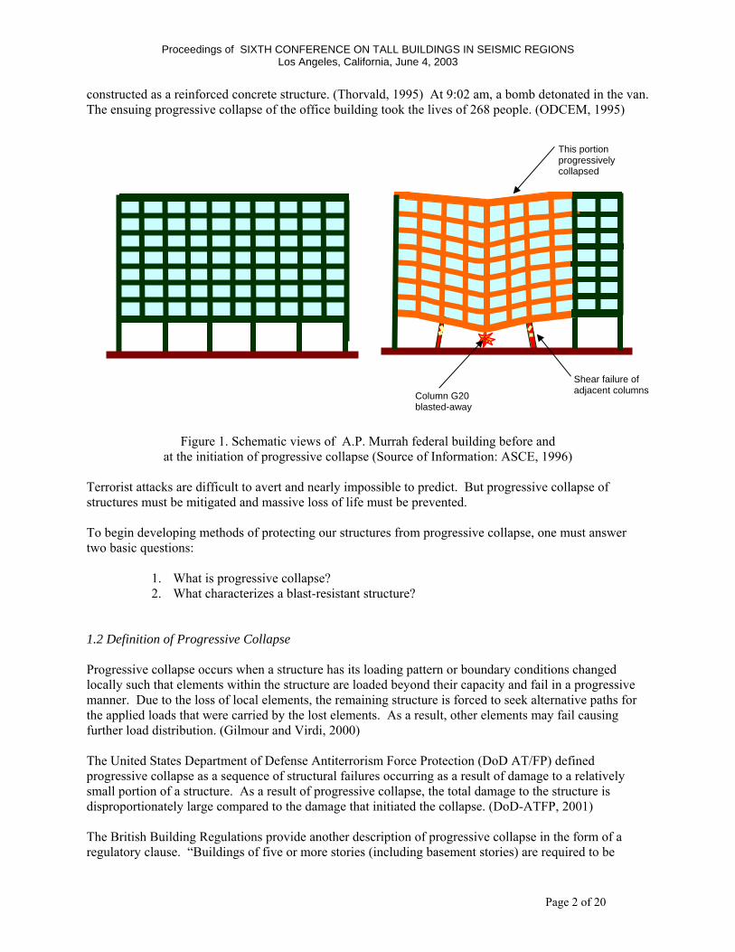
constructed as a reinforced concrete structure. (Thorvald, 1995) At 9:02 am, a bomb detonated in the van. The ensuing progressive collapse of the office building took the lives of 268 people. (ODCEM, 1995)
Figure 1. Schematic views of A.P. Murrah federal building before and at the initiation of progressive collapse (Source of Information: ASCE, 1996)
Terrorist attacks are difficult to avert and nearly impossible to predict. But progressive collapse of structures must be mitigated and massive loss of life must be prevented. To begin developing methods of protecting our structures from progressive collapse, one must answer two basic questions:
1. What is progressive collapse? 2. What characterizes a blast-resistant structure?
1.2 Definition of Progressive Collapse Progressive collapse occurs when a structure has its loading pattern or boundary conditions changed locally such that elements within the structure are loaded beyond their capacity and fail in a progressive manner. Due to the loss of local elements, the remaining structure is forced to seek alternative paths for the applied loads that were carried by the lost elements. As a result, other elements may fail causing further load distribution. (Gilmour and Virdi, 2000) The United States Department of Defense Antiterrorism Force Protection (DoD AT/FP) defined progressive collapse as a sequence of structural failures occurring as a result of damage to a relatively small portion of a structure. As a result of progressive collapse, the total damage to the structure is disproportionately large compared to the damage that initiated the collapse. (DoD-ATFP, 2001) The British Building Regulations provide another description of progressive collapse in the form of a regulatory clause. “Buildings of five or more stories (including basement stories) are required to be
Shear failure of adjacent columns Column G20
blasted-away
This portion progressively collapsed
Proceedings of SIXTH CONFERENCE ON TALL BUILDINGS IN SEISMIC REGIONS Los Angeles, California, June 4, 2003
Page 3 of 20
constructed so that, in the event of an accident, the building will not suffer collapse to an extent disproportionate to the cause of that collapse.” (Building Regulations Sch.1, A3) (italics added). In a building structure, the forceful removal of framing members will likely lead to some form of collapse. Progressive collapse occurs when local damage to a structure leads to more extensive, global instability and failure of larger portions of the structure. 1.3 Definition of Blast Resistant Structures The following characteristics are associated with blast resistant structures (Hinman, 2003)
1. Blast resistant structures are structurally redundant. 2. Blast resistant structures use ductile building materials. 3. Blast resistant structures have ductile connection design. 4. Blast resistant structures are designed to resist forces from appropriate directions.
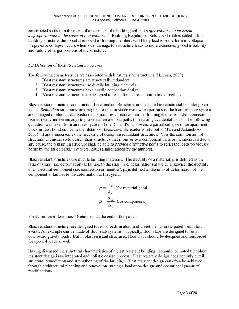
Blast resistant structures are structurally redundant. Structures are designed to remain stable under given loads. Redundant structures are designed to remain stable even when portions of the load resisting system are damaged or eliminated. Redundant structures contain additional framing elements and/or connection fixities (static indeterminacy) to provide alternate load paths for resisting accidental loads. The following quotation was taken from an investigation of the Ronan Point Towers, a partial collapse of an apartment block in East London. For further details of these case, the reader is referred to (Tan and Astaneh-Asl, 2003). It aptly underscores the necessity of designing redundant structures. "It is the common aim of structural engineers so to design their structures that if one or two component parts or members fail due to any cause, the remaining structure shall be able to provide alternative paths to resist the loads previously borne by the failed parts." (Walters, 2002) (Italics added by the authors). Blast resistant structures use ductile building materials. The ductility of a material, µ is defined as the ratio of strain (i.e. deformation) at failure, to the strain (i.e. deformation) at yield. Likewise, the ductility of a structural component (i.e. connection or member), µ, is defined as the ratio of deformation of the component at failure, to the deformation at first yield.
y
ult
εε
µ = (for material); and
y
ult
∆∆
=µ (for components)
For definition of terms see “Notations” at the end of this paper. Blast resistant structures are designed to resist loads in abnormal directions, as anticipated from blast events. An example can be made of floor slab systems. Typically, floor slabs are designed to resist downward gravity loads. But in blast resistant structures, floor slabs should be designed and reinforced for upward loads as well. Having discussed the structural characteristics of a blast resistant building, it should be noted that blast resistant design is an integrated and holistic design process. Blast resistant design does not only entail structural remediation and strengthening of the building. Blast resistant design can often be achieved through architectural planning and renovation, strategic landscape design, and operational (security) modifications.

Proceedings of SIXTH CONFERENCE ON TALL BUILDINGS IN SEISMIC REGIONS Los Angeles, California, June 4, 2003
Page 4 of 20
1.4 The Use of Catenary Action in Structures to Prevent Progressive Collapse The research project summarized herein, was the third phase of a 3-phase project. In this phase the focus of investigation was the ability of floors and cables to resist progressive collapse of existing buildings retrofitted by adding cables in the event of removal of one of exterior columns (Tan and Astaneh-Asl, 2003). The first phase investigated the ability of cables to prevent progressive collapse of new buildings (Astaneh-Asl et al., 2001a) and the second phase studied the inherent resistance of typical steel structures, without the cables, to progressive collapse in the event of removal of a column (Astaneh-Asl et al, 2001b). Magnusson Klemencic Associates (MKA) , formerly Skilling Ward Magnusson Barkshire, have used the catenary action of the steel cables in their design of a new federal office building to prevent progressive collapse due to elimination of one of the exterior columns. The first phase of this research, sponsored by MKA and General Services Administration, was initiated to study and test the application of the system to the new buildings. The second phase of the project was sponsored by the American Institute of Steel Construction and was focused on establishing inherent resistance of typical steel structures with floor decks to progressive collapse (Astaneh-Asl et al, 2001b). The last phase, summarized in this paper, extended the concept of cable catenary action used by the MKA in new buildings to retrofit of existing buildings (Tan and Astaneh-Asl, 2003). Similar to new buildings the objective here was also to prevent progressive collapse of the structure in the event of removal of one of the exterior columns. The term “catenary” is classically used to describe cables. A cable freely suspended and subjected to its own self-weight will take the shape of a catenary (Beer and Johnston, 1987) A cable is efficient at resisting axially applied tension forces; which are parallel to the length of the cable. In catenary action, a cable resists loads applied in a transverse direction along its length, such as its own weight. A cable resists transverse loads by developing internal tensile catenary forces and external reactions. When a column is destroyed as the result of an intentional or accidental blast, there is a redistribution of the gravity load through the structure. This load redistribution may cause other members to become overloaded and fail. When load redistribution occurs, it is important that alternate load paths are structurally sound. The primary purpose of using cables in catenary action is to provide reliable and secure alternate load paths after the loss of critical support members, such as columns. In catenary action, the floor and cables develop axial tension forces to resist collapse loads. A connection that consists of a column and floor beams attached with shear tabs has relatively small structural stiffness to resist the vertical displacement of a damaged column (drop column). Thus, initially, a floor resists relatively small load that is shed from a drop column. As the drop column moves downward due to building self-weight, the beams on either side of the drop column form a “V”. Column loss can create very large vertical sag, or displacement, of structures. As displacements increase, the beams develop substantial component of vertical force. The result is that the beams and floors attached to them develop internal catenary tension force.
The capacity of a structure to develop catenary action can be increased by two general methods:
1. Design structural connections and members such that they are robust and ductile enough to transfer forces and sustain deformations associated with large displacements.
2. Install cables in the floor framing system to act integrally with the floor in developing catenary action.
This project focused on using cables in catenary action to prevent progressive collapse of structures.

Proceedings of SIXTH CONFERENCE ON TALL BUILDINGS IN SEISMIC REGIONS Los Angeles, California, June 4, 2003
Page 5 of 20
1.5 Objectives and Scope The scope of the research and development program consisted of:
1. Test the full scale specimen representing typical existing modern steel structures with simple shear tab connections and establish their performance after removal of façade columns.
2. Develop a cable-based retrofit system that can prevent progressive collapse of the specimen after removal of one column. Develop the system such that construction techniques and procedures are applicable for use on existing building structures with ease and economy and preferably from outside without major impact on the occupants.
3. Apply the retrofit system to the full-scale specimen using the same procedures to be followed in actual site.
4. Remove the column and perform column push-down test of specimen. 5. Analyze test results and report on specimen behavior. 6. Formulate design and construction recommendations for retrofit of existing steel buildings
using steel cables to prevent their progressive collapse. 2. Experimental Procedure for Steel Cable Retrofit 2.1 Test Specimen
This research project investigated the capacity of a single-floor from a steel structure to resist progressive collapse through catenary action of its floor-framing members. Experimental results were gathered from drop column testing of a full-scale single-story steel specimen, performed in Davis Hall at UC Berkeley (Figure 2). A brief discussion of the test specimen, the concept of drop column testing, the cable retrofit procedure, and the instrumentation of the specimen follows.
Figure 2. Overall View of Test Specimen with Drop Column Displaced
22 inches Downward and Holding.
Bottom of
Drop ColumnTwo Retrofit Cables

Proceedings of SIXTH CONFERENCE ON TALL BUILDINGS IN SEISMIC REGIONS Los Angeles, California, June 4, 2003
Page 6 of 20
The specimen was a single-story steel floor system with composite concrete floor slab. The specimen measured approximately 20 feet (6.1 m) wide and 60 feet (18.3 m) long in plan (Figures 3 and 4). The finished concrete floor slab was 6 feet -3 ½ inches (1.9 m) above the laboratory floor. The specimen had 4 spans in the longitudinal direction and one span in the transverse direction. The slab was constructed using cast-in-place reinforced concrete (reinforced with wire mesh), over metal deck. W18x35 longitudinal beams and W21x44 transverse beams supported the slab. Then W14x61 wide-flange columns supported the floor framing, Figure 3. Columns, beams and steel connection plates were grade ASTM A36 (Fy=36 ksi (248 MPa)). The floor slab was constructed using 4000 psi (28 MPa) concrete. Bolts at shear tab connections were 7/8-inch (22 mm) diameter grade ASTM A325. Welding was performed using E70xx (70ksi (483 MPa)) electrodes. This test specimen was retrofitted with two high strength steel cables. These cables were ¾-inch (19 mm) diameter ASTM A586 zinc-coated helical steel wire structural strands. The cables were attached to the exterior W18x35 beams on the south side of the test specimen. The cables were attached along the top and bottom fillet region of the W18x35 beams. Each cable was approximately 735 inches long (18.7 m).
Figure 3. Plan View of Test Specimen
Figure 4. Elevation of South Frame.
Transverse beam (W21x44)
West Beam (W18x35)
Drop column (W14x61)
East Beam (W18x35)
All Columns were W14x61Two ¾: dia Cables on the Outside Face of Beam Web
Proceedings of SIXTH CONFERENCE ON TALL BUILDINGS IN SEISMIC REGIONS Los Angeles, California, June 4, 2003
Page 7 of 20
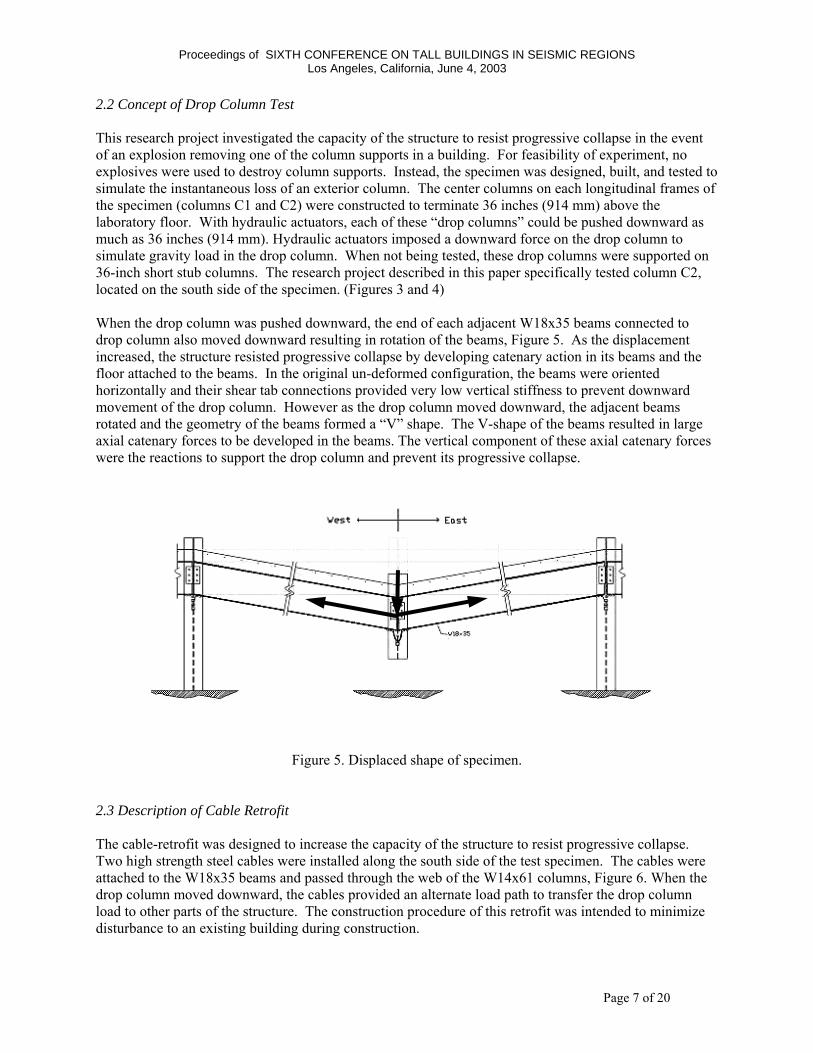
2.2 Concept of Drop Column Test This research project investigated the capacity of the structure to resist progressive collapse in the event of an explosion removing one of the column supports in a building. For feasibility of experiment, no explosives were used to destroy column supports. Instead, the specimen was designed, built, and tested to simulate the instantaneous loss of an exterior column. The center columns on each longitudinal frames of the specimen (columns C1 and C2) were constructed to terminate 36 inches (914 mm) above the laboratory floor. With hydraulic actuators, each of these “drop columns” could be pushed downward as much as 36 inches (914 mm). Hydraulic actuators imposed a downward force on the drop column to simulate gravity load in the drop column. When not being tested, these drop columns were supported on 36-inch short stub columns. The research project described in this paper specifically tested column C2, located on the south side of the specimen. (Figures 3 and 4) When the drop column was pushed downward, the end of each adjacent W18x35 beams connected to drop column also moved downward resulting in rotation of the beams, Figure 5. As the displacement increased, the structure resisted progressive collapse by developing catenary action in its beams and the floor attached to the beams. In the original un-deformed configuration, the beams were oriented horizontally and their shear tab connections provided very low vertical stiffness to prevent downward movement of the drop column. However as the drop column moved downward, the adjacent beams rotated and the geometry of the beams formed a “V” shape. The V-shape of the beams resulted in large axial catenary forces to be developed in the beams. The vertical component of these axial catenary forces were the reactions to support the drop column and prevent its progressive collapse.
Figure 5. Displaced shape of specimen. 2.3 Description of Cable Retrofit The cable-retrofit was designed to increase the capacity of the structure to resist progressive collapse. Two high strength steel cables were installed along the south side of the test specimen. The cables were attached to the W18x35 beams and passed through the web of the W14x61 columns, Figure 6. When the drop column moved downward, the cables provided an alternate load path to transfer the drop column load to other parts of the structure. The construction procedure of this retrofit was intended to minimize disturbance to an existing building during construction.
Proceedings of SIXTH CONFERENCE ON TALL BUILDINGS IN SEISMIC REGIONS Los Angeles, California, June 4, 2003
Page 8 of 20
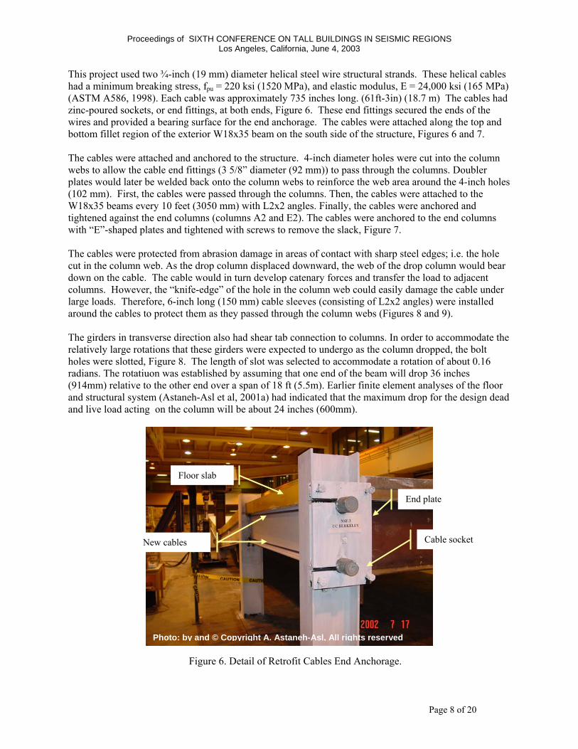
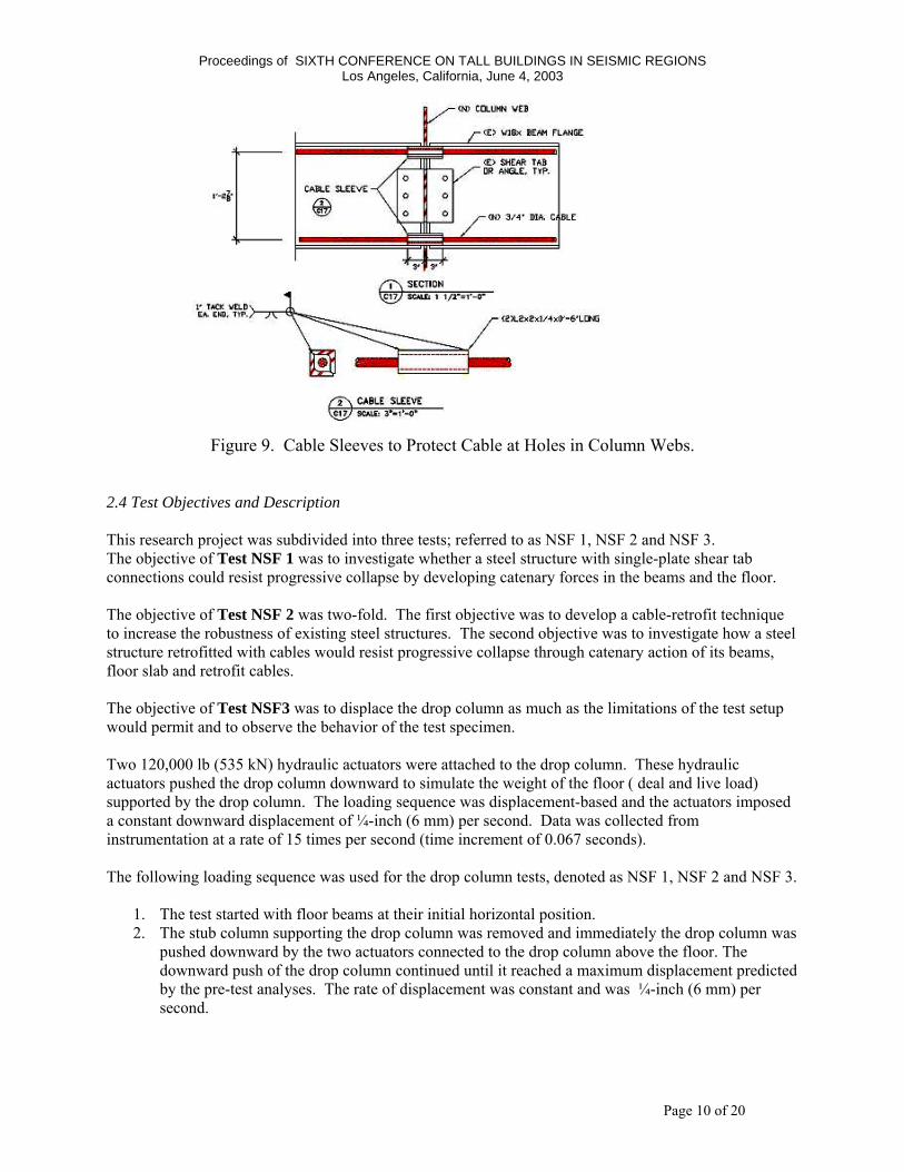
This project used two ¾-inch (19 mm) diameter helical steel wire structural strands. These helical cables had a minimum breaking stress, fpu = 220 ksi (1520 MPa), and elastic modulus, E = 24,000 ksi (165 MPa) (ASTM A586, 1998). Each cable was approximately 735 inches long. (61ft-3in) (18.7 m) The cables had zinc-poured sockets, or end fittings, at both ends, Figure 6. These end fittings secured the ends of the wires and provided a bearing surface for the end anchorage. The cables were attached along the top and bottom fillet region of the exterior W18x35 beam on the south side of the structure, Figures 6 and 7. The cables were attached and anchored to the structure. 4-inch diameter holes were cut into the column webs to allow the cable end fittings (3 5/8” diameter (92 mm)) to pass through the columns. Doubler plates would later be welded back onto the column webs to reinforce the web area around the 4-inch holes (102 mm). First, the cables were passed through the columns. Then, the cables were attached to the W18x35 beams every 10 feet (3050 mm) with L2x2 angles. Finally, the cables were anchored and tightened against the end columns (columns A2 and E2). The cables were anchored to the end columns with “E”-shaped plates and tightened with screws to remove the slack, Figure 7. The cables were protected from abrasion damage in areas of contact with sharp steel edges; i.e. the hole cut in the column web. As the drop column displaced downward, the web of the drop column would bear down on the cable. The cable would in turn develop catenary forces and transfer the load to adjacent columns. However, the “knife-edge” of the hole in the column web could easily damage the cable under large loads. Therefore, 6-inch long (150 mm) cable sleeves (consisting of L2x2 angles) were installed around the cables to protect them as they passed through the column webs (Figures 8 and 9). The girders in transverse direction also had shear tab connection to columns. In order to accommodate the relatively large rotations that these girders were expected to undergo as the column dropped, the bolt holes were slotted, Figure 8. The length of slot was selected to accommodate a rotation of about 0.16 radians. The rotatiuon was established by assuming that one end of the beam will drop 36 inches (914mm) relative to the other end over a span of 18 ft (5.5m). Earlier finite element analyses of the floor and structural system (Astaneh-Asl et al, 2001a) had indicated that the maximum drop for the design dead and live load acting on the column will be about 24 inches (600mm).
Figure 6. Detail of Retrofit Cables End Anchorage.
New cables
Floor slab
Cable socket
End plate
Photo: by and © Copyright A. Astaneh-Asl, All rights reserved

Proceedings of SIXTH CONFERENCE ON TALL BUILDINGS IN SEISMIC REGIONS Los Angeles, California, June 4, 2003
Page 9 of 20
Figure 8. Cable Sleeves at Drop Column.
SHEAR TAB CONNECTION OF TRANSVERSE GIRDER WITH SLOTTED HOLES
Figure 7. End Column Detail for Cable Retrofit
Proceedings of SIXTH CONFERENCE ON TALL BUILDINGS IN SEISMIC REGIONS Los Angeles, California, June 4, 2003
Page 10 of 20
Figure 9. Cable Sleeves to Protect Cable at Holes in Column Webs. 2.4 Test Objectives and Description This research project was subdivided into three tests; referred to as NSF 1, NSF 2 and NSF 3. The objective of Test NSF 1 was to investigate whether a steel structure with single-plate shear tab connections could resist progressive collapse by developing catenary forces in the beams and the floor. The objective of Test NSF 2 was two-fold. The first objective was to develop a cable-retrofit technique to increase the robustness of existing steel structures. The second objective was to investigate how a steel structure retrofitted with cables would resist progressive collapse through catenary action of its beams, floor slab and retrofit cables. The objective of Test NSF3 was to displace the drop column as much as the limitations of the test setup would permit and to observe the behavior of the test specimen. Two 120,000 lb (535 kN) hydraulic actuators were attached to the drop column. These hydraulic actuators pushed the drop column downward to simulate the weight of the floor ( deal and live load) supported by the drop column. The loading sequence was displacement-based and the actuators imposed a constant downward displacement of ¼-inch (6 mm) per second. Data was collected from instrumentation at a rate of 15 times per second (time increment of 0.067 seconds). The following loading sequence was used for the drop column tests, denoted as NSF 1, NSF 2 and NSF 3.
1. The test started with floor beams at their initial horizontal position. 2. The stub column supporting the drop column was removed and immediately the drop column was
pushed downward by the two actuators connected to the drop column above the floor. The downward push of the drop column continued until it reached a maximum displacement predicted by the pre-test analyses. The rate of displacement was constant and was ¼-inch (6 mm) per second.
Proceedings of SIXTH CONFERENCE ON TALL BUILDINGS IN SEISMIC REGIONS Los Angeles, California, June 4, 2003
Page 11 of 20
3. After maximum displacement reached, the drop column was partially unloaded by pushing it up by about 2 inches. This unloading allowed the actuator forces to drop to a level safe for observations below the deformed floor.
4. Visual observations were performed. 5. Completely unloaded the drop column by pushing it up until the beams reached their initial
horizontal position. 6. Prepared the specimen and data acquisition system for the next test. 7.
Table 1. Summary of Tests NSF 1, NSF 2 and NSF 3
Test Shear tabs1 Cables2
Maximum drop column
displacement , inch (mm)
Displacement Rate, inch/sec
(mm/sec)
NSF 1 Yes No 22 (560) ¼ (6) NSF 2 Yes Yes 22 (560) ¼ (6) NSF 3 Yes Yes 32 (810) ¼ (6)
1 Shear tabs were installed at grid locations B2, C2, and D2. 2 Retrofit cables installed along south side of specimen, frame Line 2.
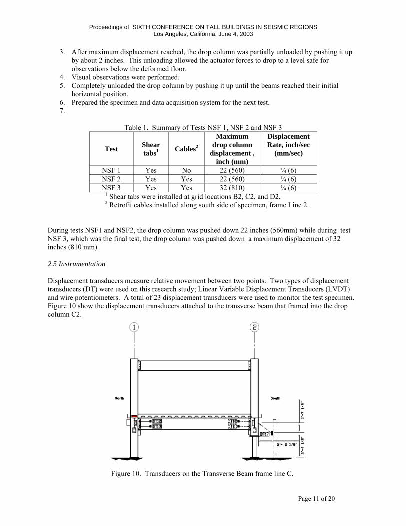
During tests NSF1 and NSF2, the drop column was pushed down 22 inches (560mm) while during test NSF 3, which was the final test, the drop column was pushed down a maximum displacement of 32 inches (810 mm). 2.5 Instrumentation Displacement transducers measure relative movement between two points. Two types of displacement transducers (DT) were used on this research study; Linear Variable Displacement Transducers (LVDT) and wire potentiometers. A total of 23 displacement transducers were used to monitor the test specimen. Figure 10 show the displacement transducers attached to the transverse beam that framed into the drop column C2.
Figure 10. Transducers on the Transverse Beam frame line C.
Proceedings of SIXTH CONFERENCE ON TALL BUILDINGS IN SEISMIC REGIONS Los Angeles, California, June 4, 2003
Page 12 of 20
The strain gages for this research project consisted of rosettes and linear gages. A total of 24 strain gages (SG) were used to monitor this specimen.
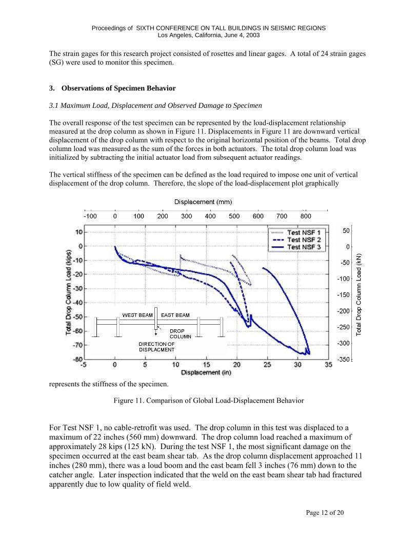
3. Observations of Specimen Behavior 3.1 Maximum Load, Displacement and Observed Damage to Specimen The overall response of the test specimen can be represented by the load-displacement relationship measured at the drop column as shown in Figure 11. Displacements in Figure 11 are downward vertical displacement of the drop column with respect to the original horizontal position of the beams. Total drop column load was measured as the sum of the forces in both actuators. The total drop column load was initialized by subtracting the initial actuator load from subsequent actuator readings. The vertical stiffness of the specimen can be defined as the load required to impose one unit of vertical displacement of the drop column. Therefore, the slope of the load-displacement plot graphically
represents the stiffness of the specimen.
Figure 11. Comparison of Global Load-Displacement Behavior
For Test NSF 1, no cable-retrofit was used. The drop column in this test was displaced to a maximum of 22 inches (560 mm) downward. The drop column load reached a maximum of approximately 28 kips (125 kN). During the test NSF 1, the most significant damage on the specimen occurred at the east beam shear tab. As the drop column displacement approached 11 inches (280 mm), there was a loud boom and the east beam fell 3 inches (76 mm) down to the catcher angle. Later inspection indicated that the weld on the east beam shear tab had fractured apparently due to low quality of field weld.
Proceedings of SIXTH CONFERENCE ON TALL BUILDINGS IN SEISMIC REGIONS Los Angeles, California, June 4, 2003
Page 13 of 20
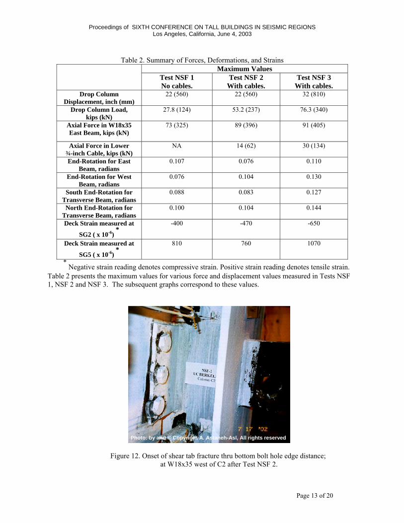
Table 2. Summary of Forces, Deformations, and Strains
Maximum Values Test NSF 1 No cables.
Test NSF 2 With cables.
Test NSF 3 With cables.
Drop Column Displacement, inch (mm)
22 (560) 22 (560) 32 (810)
Drop Column Load, kips (kN)
27.8 (124) 53.2 (237) 76.3 (340)
Axial Force in W18x35 East Beam, kips (kN)
73 (325) 89 (396) 91 (405)
Axial Force in Lower ¾-inch Cable, kips (kN)
NA 14 (62) 30 (134)
End-Rotation for East Beam, radians
0.107 0.076 0.110
End-Rotation for West Beam, radians
0.076 0.104 0.130
South End-Rotation for Transverse Beam, radians
0.088 0.083 0.127
North End-Rotation for Transverse Beam, radians
0.100 0.104 0.144
Deck Strain measured at
SG2 ( x 10-6) *
-400 -470 -650
Deck Strain measured at
SG5 ( x 10-6) *
810 760 1070
* Negative strain reading denotes compressive strain. Positive strain reading denotes tensile strain.
Table 2 presents the maximum values for various force and displacement values measured in Tests NSF 1, NSF 2 and NSF 3. The subsequent graphs correspond to these values.
Figure 12. Onset of shear tab fracture thru bottom bolt hole edge distance; at W18x35 west of C2 after Test NSF 2.
Photo: by and © Copyright A. Astaneh-Asl, All rights reserved

Proceedings of SIXTH CONFERENCE ON TALL BUILDINGS IN SEISMIC REGIONS Los Angeles, California, June 4, 2003
Page 14 of 20
For Test NSF 2, the damaged shear tab was replaced and re-welded and the specimen was retrofitted with two ¾-inch (19 mm) diameter high-strength steel cables. These cables were attached to the beams and columns on the south elevation of the specimen. In Test NSF 2, the drop column was displaced to a maximum of 22 inches (560 mm) downward. The drop column load reached a maximum of approximately 53 kips (236 kN). During Test NSF 2, the most significant damage on the specimen was the onset of edge distance fracture of the shear tab bolt holes, Figure 12. Large displacements of the drop column resulted in beam end-rotations of up to 0.104 radians on the west beam. As the drop column displacement approached 9.5 inches (240 mm), the bottom bolt of the west beam shear tab initiated edge distance fracture. At a drop column displacement of 20 inches (508 mm), a complete edge distance fracture of the bottom bolt hole was observed, Figure 12. Test NSF 3 was performed approximately 60 minutes after Test NSF 2. The specimen was unaltered from the previous test. The objective of Test NSF3 was to displace the drop column as much as the limitations of the test setup would permit and to observe the behavior. In Test NSF 3, the drop column was displaced to a maximum of 32 inches (810 mm) downward. The drop column load reached a maximum of approximately 76 kips (338 kN).
Figure 13. After Test NSF 3. (a) Overall View of Drop Column Specimen, (b) Shear Tab Fracture Thru Bolt Hole Edge Distance at W18x35 West of C2 (west beam); and (c) Detail of shear tab fracture at west beam.
Photos: by and © Copyright A. Astaneh-Asl, All rights reserved
Proceedings of SIXTH CONFERENCE ON TALL BUILDINGS IN SEISMIC REGIONS Los Angeles, California, June 4, 2003
Page 15 of 20
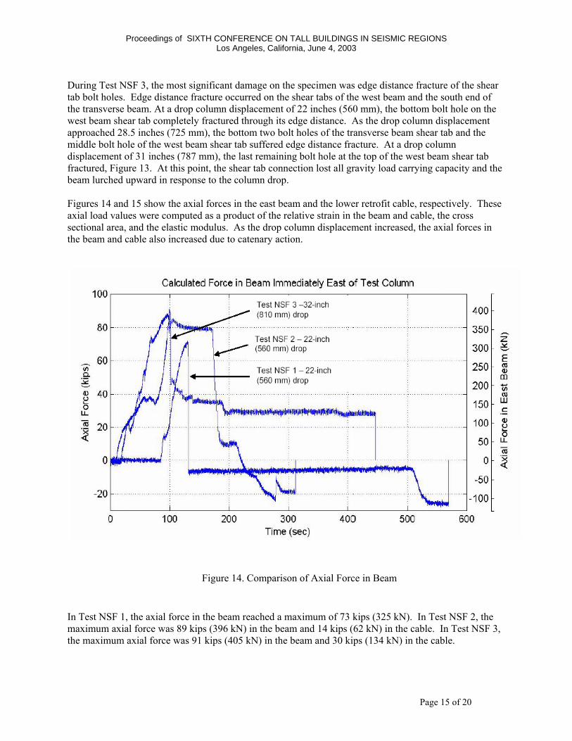
During Test NSF 3, the most significant damage on the specimen was edge distance fracture of the shear tab bolt holes. Edge distance fracture occurred on the shear tabs of the west beam and the south end of the transverse beam. At a drop column displacement of 22 inches (560 mm), the bottom bolt hole on the west beam shear tab completely fractured through its edge distance. As the drop column displacement approached 28.5 inches (725 mm), the bottom two bolt holes of the transverse beam shear tab and the middle bolt hole of the west beam shear tab suffered edge distance fracture. At a drop column displacement of 31 inches (787 mm), the last remaining bolt hole at the top of the west beam shear tab fractured, Figure 13. At this point, the shear tab connection lost all gravity load carrying capacity and the beam lurched upward in response to the column drop. Figures 14 and 15 show the axial forces in the east beam and the lower retrofit cable, respectively. These axial load values were computed as a product of the relative strain in the beam and cable, the cross sectional area, and the elastic modulus. As the drop column displacement increased, the axial forces in the beam and cable also increased due to catenary action.
In Test NSF 1, the axial force in the beam reached a maximum of 73 kips (325 kN). In Test NSF 2, the maximum axial force was 89 kips (396 kN) in the beam and 14 kips (62 kN) in the cable. In Test NSF 3, the maximum axial force was 91 kips (405 kN) in the beam and 30 kips (134 kN) in the cable.
Figure 14. Comparison of Axial Force in Beam

Proceedings of SIXTH CONFERENCE ON TALL BUILDINGS IN SEISMIC REGIONS Los Angeles, California, June 4, 2003
Page 16 of 20
Figure 16 shows the end-rotation of the east beam. These rotations were computed from displacement
Figure 15. Comparison of Axial Force in Cable
Figure 16. Rotation of East Beam Connection at Test Column
Proceedings of SIXTH CONFERENCE ON TALL BUILDINGS IN SEISMIC REGIONS Los Angeles, California, June 4, 2003
Page 17 of 20
transducers mounted on the beam webs that connected to the drop column. Beam end-rotation was computed as the difference of the top and bottom transducer reading, divided by the vertical distance between the transducers. During Test NSF 1, the east beam had a relative end-rotation of approximately 0.07 radians when the east beam shear tab suffered a brittle weld fracture (Figure 16). During Test NSF 2, the east beam had a maximum end-rotation of 0.076 radians. During Test NSF 3, the east beam had a maximum end-rotation of 0.110 radians.
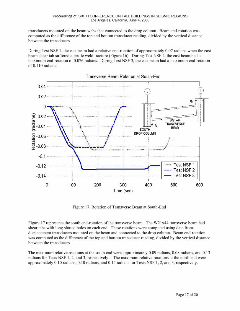
Figure 17 represents the south end-rotation of the transverse beam. The W21x44 transverse beam had shear tabs with long slotted holes on each end. These rotations were computed using data from displacement transducers mounted on the beam and connected to the drop column. Beam end-rotation was computed as the difference of the top and bottom transducer reading, divided by the vertical distance between the transducers. The maximum relative rotations at the south end were approximately 0.09 radians, 0.08 radians, and 0.13 radians for Tests NSF 1, 2, and 3, respectively. The maximum relative rotations at the north end were approximately 0.10 radians, 0.10 radians, and 0.14 radians for Tests NSF 1, 2, and 3, respectively.
Figure 17. Rotation of Transverse Beam at South-End
Proceedings of SIXTH CONFERENCE ON TALL BUILDINGS IN SEISMIC REGIONS Los Angeles, California, June 4, 2003
Page 18 of 20
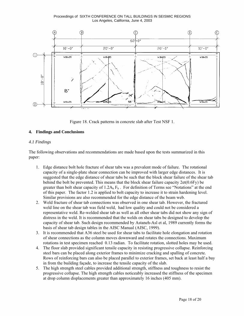
Figure 18. Crack patterns in concrete slab after Test NSF 1. 4. Findings and Conclusions 4.1 Findings The following observations and recommendations are made based upon the tests summarized in this paper:
1. Edge distance bolt hole fracture of shear tabs was a prevalent mode of failure. The rotational
capacity of a single-plate shear connection can be improved with larger edge distances. It is suggested that the edge distance of shear tabs be such that the block shear failure of the shear tab behind the bolt be prevented. This means that the block shear failure capacity 2et(0.6Fy) be greater than bolt shear capacity of 1.2Ab Fb . For definition of Terms see “Notations” at the end of this paper. The factor 1.2 is applied to bolt capacity to increase it to strain hardening level. Similar provisions are also recommended for the edge distance of the beam web.
2. Weld fracture of shear tab connections was observed in one shear tab. However, the fractured weld line on the shear tab was field weld, had low quality and could not be considered a representative weld. Re-welded shear tab as well as all other shear tabs did not show any sign of distress in the weld. It is recommended that the welds on shear tabs be designed to develop the capacity of shear tab. Such design recommended by Astaneh-Asl et al, 1989 currently forms the basis of shear tab design tables in the AISC Manual (AISC, 1999).
3. It is recommended that A36 steel be used for shear tabs to facilitate hole elongation and rotation of shear connections as the column moves downward and rotates the connections. Maximum rotations in test specimen reached 0.13 radian. To facilitate rotation, slotted holes may be used.
4. The floor slab provided significant tensile capacity in resisting progressive collapse. Reinforcing steel bars can be placed along exterior frames to minimize cracking and spalling of concrete. Rows of reinforcing bars can also be placed parallel to exterior frames, set back at least half a bay in from the building façade, to increase the tensile capacity of the slab.
5. The high strength steel cables provided additional strength, stiffness and toughness to resist the progressive collapse. The high strength cables noticeably increased the stiffness of the specimen at drop column displacements greater than approximately 16 inches (405 mm).
Proceedings of SIXTH CONFERENCE ON TALL BUILDINGS IN SEISMIC REGIONS Los Angeles, California, June 4, 2003
Page 19 of 20
6. The high strength steel cables provided an adequate alternate load path for the drop column load. The cables resisted their proportionate catenary forces without failure. The end columns supported additional load that was shed from the drop column with a maximum of ½” inward displacement.
7. The floor slab was able to tolerate the in-plane compression forces due to tension in the catenary cables.
4.2 Conclusion It was the purpose of this research project to demonstrate that catenary action of steel cables can potentially be used to prevent progressive collapse. In the steel-framed test specimen, beams, floor and cables acted together to develop catenary action. This catenary action prevented progressive collapse by redistributing gravity load through reliable load paths. Based on findings from experimental observations, recommendations were made for more robust structural steel connections. Acknowledgements This project summarized herein was funded by the National Science Foundation (www.NSF.gov). Many thanks are due to the staff of the structural engineering laboratory of the Department of Civil and Environmental Engineering of the University of California at Berkeley. In particular, the efforts of William Mac Cracken, Jeff Higginbotham, Richard Parsons, Douglas Zulaica, Chris Moy and Frank Latora were essential in assembling the specimen and in instrumentation and data acquisition. Valuable technical assistance was also provided by Dr. Xiao-Xiong Zha, Ricky Hwa and Albert Wong. Input by Qiuhong Zhao and Dr. Lev Stepanov is greatly appreciated. Past graduate student researchers Roger Jung, Erik Madsen and Brent Jones of UC Berkeley were instrumental in the construction and development of the cable-retrofit test specimen used in these studies. The original full-scale specimen was constructed for the tests of cable system which was funded by the General Services Administration and the MKA (formerly the SWMB) of Seattle. The original specimen was designed by MKA engineers. The input and technical advice received from Brian Dickson of MKA and Willie Hirano of General Services Administration were very valuable and are sincerely appreciated. John Crawford of Karagozian & Case mentioned the idea of placing cables in the corners of a wide flange shape to the second author at a meeting of the AISC Committee for Blast and Impact Resistant Design of Buildings in 2001. References AISC, (1999) “Manual of Steel Construction-LRFD”, American Institute of Steel Construction, Chicago, IL. ASCE, (1996). “The Oklahoma City Bombing: Improving Building Performance Through Multi-Hazard Mitigation.” Report FEMA 277. Federal Emergency Management Agency Mitigation Directorate. Reston, VA. Astaneh-Asl, A., Madsen E.A., Noble, C, Jung, R., McCallen D., Hoehler M.S., Li, W. and Hwa, R. (2001a) “Use of Catenary Cables to Prevent Progressive Collapse of Buildings”, Report Number UCB/CEE-Steel-2001/02, Dept. of Civil and Env. Engrg., Univ. of California, Berkeley. Astaneh-Asl, A., Jones, B., Zhao, Y, and Hwa, R. (2001b) “Progressive Collapse Resistance of Steel Building Floors”, Report Number UCB/CEE-Steel-2001/03, Dept. of Civil and Env. Engrg., Univ. of California, Berkeley.
Proceedings of SIXTH CONFERENCE ON TALL BUILDINGS IN SEISMIC REGIONS Los Angeles, California, June 4, 2003
Page 20 of 20
Astaneh-Asl, A., Liu, J. and McMullin, K. M. (2002), "Behavior and Design of Single Plate Shear Connections", J. of Constructional Steel Research, 58, (2002) pp.1121-1141. ASTM A586. (1998) “Standard Specification for Zinc-Coated Parallel and Helical Steel Wire Structural Strand and Zinc-Coated Wire for Spun-in-Place Structural Strand”, American Society for Testing and Materials, West Conshohocken, Pennsylvania, pp. 104-107. Beer, F., Johnston, E.R. (1987). Mechanics for Engineers, Statics, 4th Ed.. McGraw-Hill, Inc. New York. Carino, N.J., Lew, H.S., eds. (2001). “Summary of NIST/GSA Workshop on Application of Seismic Rehabilitation Technologies to Mitigate Blast-Induced Progressive Collapse”. Proceedings. National Institute of Standards and Technology (NIST). http://fire.nist.gov/bfrlpubs/build01/art055.html CETS. (1995). Protecting Buildings from Bomb Damage. Commission on Engineering and Technical Systems. National Academy Press. Washington D.C. http://www.nap.edu/books/0309053757/html/index.html DoD AT/FP. (2001) “Interim Antiterrorism/Force Protection (AT/FP) Construction Standards. Guidance on Structural Requirements”. United States Department of Defense, Washington D.C.. Esper, P., Hadden, D. (2000). “Dynamic Response of Buildings and Floor Slabs to Blast Loading.” Abnormal Loading on Structures, Virdi, K.S. et al (Eds.). E & FN Spon. London, United Kingdom. Gilmour, J.R., Virdi, K.S. (2000). “Modelling Progressive Collapse of Structures as a Result of Explosion.” Abnormal Loading on Structures. E & FN Spon. London, United Kingdom. Hinman, E. (2003). “Retrofitting Buildings to Resist Explosive Attack”. Presentation to the Existing Buildings Committee of the Structural Engineers Association of Northern California (SEAONC). January 8, 2003. San Francisco, California. Tan , S. and Astaneh-Asl, A. (2003) “Testing a Retrofit Concept to Prevent Progressive Collapse”, Report Number UCB/CEE-Steel-2003/02, Dept. of Civil and Env. Engrg., Univ. of California, Berkeley. Thorvald, S. (1995). “Engineers and Building Collapse Response: From Mexico '85 To Oklahoma '95”. EQE Review Fall 1995 Issue. EQE International. San Francisco, California. Watson, A.J. (2002). “Loading from Explosions and Impact”. Dynamic Loading and Design of Structures. Spon Press. London, United Kingdom Notation Ab = area of a bolt e = edge distance t = thickness of shear tab Fy = specified yield stress for shear tab or beam Fb = specified shear strength of bolt εult = strain at failure εy = strain at yield ∆ult = deformation at failure ∆y = deformation at yield.
Related Documents