Notice �Read and understand these instructions before attempting any unpacking, assembly, operation or maintenance of the circuit breaker. �This instruction manual should be applied only to U-Series Vacuum Contactors. �This instruction manual does not include all items regarding installation and maintenance procedures. �For more information, please contact HYUNDAI Heavy Industries Co., Ltd. or one of our partners. �당사 고압진공접촉기를 사용하시기 전에 반드시 본 취급설명서를 상세히 읽으신 후 설치 및 운전하십시오. �본 취급설명서는 U-Series 고압진공접촉기에만 적용됩니다. �본 취급설명서에는 설치 및 유지∙보수에 관련된 모든 절차가 포함되어 있지는 않으므로 제품에 대해 더 많은 정보를 필요로 하시는 경우에는 당사로 연락하시기 바랍니다. �기술적인 문의 및 A/S사항은 가까운 지사 혹은 뒷 표지의 본사 설계 또는 A/S 담당자에게 문의 바랍니다. �본 취급설명서는 품질개선을 위하여 사전예고 없이 변경될 수 있습니다. U - Series 고압진공접촉기 취급설명서 Vacuum ContactorlInstruction Manual

Welcome message from author
This document is posted to help you gain knowledge. Please leave a comment to let me know what you think about it! Share it to your friends and learn new things together.
Transcript
N o t i c e�Read and understand these instructions before attempting any
unpacking, assembly, operation or maintenance of the circuitbreaker.
�This instruction manual should be applied only to U-SeriesVacuum Contactors.
�This instruction manual does not include all items regardinginstallation and maintenance procedures.
�For more information, please contact HYUNDAI Heavy IndustriesCo., Ltd. or one of our partners.
�당사 고압진공접촉기를 사용하시기 전에 반드시 본 취급설명서를 상세히읽으신 후 설치 및 운전하십시오.
�본 취급설명서는 U-Series 고압진공접촉기에만 적용됩니다.
�본 취급설명서에는 설치 및 유지∙보수에 관련된 모든 절차가 포함되어있지는 않으므로 제품에 해 더 많은 정보를 필요로 하시는 경우에는당사로 연락하시기 바랍니다.
�기술적인 문의 및 A/S사항은 가까운 지사 혹은 뒷 표지의 본사 설계 또는A/S 담당자에게 문의 바랍니다.
�본 취급설명서는 품질개선을 위하여 사전예고 없이 변경될 수 있습니다.
U-Series
고압진공접촉기취급설명서
Vacuum ContactorlInstruction Manual

Safety Practices 안전 조항
2 << U-Series Vacuum Contactor Instruction Manual
Safety Practices
This instruction manual applies only to the U-Series
Vacuum Contactor regarding installation and
maintenance procedures.
Installing and maintaining these products improperly may
result in serious personal injury, property damage, or even
death. Therefore this instruction manual must be read and
understood at every step in unpacking, assembly,
operation, and maintenance of contactors.
Only qualified persons familiar with installing and
maintaining contactors are permitted to work on
contactors, and this instruction manual should be
accessible to those persons at all times.
If further information is required, please contact Hyundai
Heavy Industries Co., Ltd.
Signal Words
Signal words used in this instruction manual are DANGER,
WARNING, and CAUTION depending on the situation.
Indicates an imminently hazardous point which, if ignored,
will result in death or serious injury.
Indicates a potentially hazardous point which, if ignored,
could result in death or serious injury.
Indicates a potentially hazardous point which, if ignored,
may result in minor or moderate injury.
This signal also warns operators to work safely.
Safety Practices During Installation
안전 조항
본 취급 설명서는 U-Series 고압진공접촉기의 운전 및 안전에
관한 중요한 내용을 기술하 습니다.
제품을 부적절하게 설치하거나 유지�보수시에는 치명적인 인명 피해 및
재산 손실이 유발될 수 있으므로 포장해체, 조립, 작동, 혹은 유지�보수를
하시기 전에 반드시 이 취급설명서를 충분히 읽고 이해하시기 바랍니다.
설치 및 유지�보수는 유자격자나 전문 지식을 보유한 사람이 행하십시오.
이 취급설명서는 U-Series 고압진공접촉기에만 적용되며,
설치나 유지�보수에 관련된 절차가 모두 포함되어 있지 않으므로 제품에
해 더 많은 정보를 필요로 하시는 경우에는 당사로 연락하시기 바랍니다.
기호 설명
본 취급 설명서에서는 안전 주의사항을 위험 정도에 따라『위험』, 『경고』,
『주의』로 구분하고 있습니다.
취급을 잘못 했을 경우 사망 또는 중상을 입을 절박한 위험 상태를 나타내며,
가장 위험한 상황입니다.
피하지 않으면, 사망 또는 중상을 입을 수 있는 잠재적인 위험 상태를 나타
냅니다.
피하지 않으면, 약한 상해나 경상이 발생할지 모르는 잠재적인 위험 상태를
나타냅니다. 또한 이 표시는 불안전한 행동에 한 경고입니다.
설치(취부, 접속)시의 주의사항
�Excessive heavy weight could cause serious injury, or damage. To avoid thissituation, please don’t transport a contactoron a lifting facility in the raised position.
�Do not work on contactors unless the primarycircuits are disconnected by the visible breaker.
�When connecting bus-bars, tighten boltsaccording to our standards.
�Contactors should be tightly mounted on ahorizontal plane.
�Do not install the contactors in areas withhigh temperature, high humidity, dust,corrosive, or vibrating conditions.
�Concrete dust or any other dust should notbe inside the product when it installed. It can cause fire or misoperation.
�제품 이동시 낙하로 인한 심각한 사고 및 제품 손상
이 우려됩니다. 이를 방지하기 위하여 제품 이동시
높이 올려진 상태로 이동하지 않도록 하십시오.
�설치에 앞서 모든 전원을 차단하기 위해 앞단의
차단기나 그러한 종류의 제품을 반드시 open
시키십시오. 감전의 위험이 있습니다.
�단자 bolt는 표준체결 torque로 확실하게
조이십시오. 화재의 위험이 있습니다.
�본 제품은 수평하고 평평한 면에 단단하게 취부
하여 고정시키십시오.
�고온, 다습, 분진, 부식성 가스, 진동, 충격 등
좋지 못한 환경에 설치하지 마십시오.
화재, 동작 불량이 발생할 수 있습니다.
�먼지, 콘크리트 가루, 철분 등의 미물질 및 빗물
등이 본제품의 내부에 들어가지 않도록 설치
하십시오. 화재, 동작 불량이 발생할 수 있습니다.

Safety Practices During Operation
Safety Practices During Maintenance
조작시의 주의사항
유지�보수시 주의사항
고압진공접촉기 취급설명서>> 3
VC | U-Series
�Do not touch the primary circuit and the control circuit.
�통전되고 있는 주회로 및 제어회로 단자부에는
접촉하지 마십시오.
감전에 의한 제품 손상이나 인명 사고의 위험이
있습니다.
�Do not work on contactors unless theprimary circuits are disconnected by the visible breaker.
�Replace the vacuum interrupter when the wipe is below 0.5 mm.
�유지 보수 작업은 앞단의 주회로 차단기를
반드시 open 시키고 주회로에 전류가 공급되지
않거나 충전되어 있지 않은 것을 확인한 후
작업을 행하십시오. 감전의 위험이 있습니다.
�Wipe가 0.5 이하가 되면 진공밸브를 교체하여
주십시오. 제품 손상이 발생할 수 있습니다.
�Failure to correctly maintain theequipment could result in serious injuryand product failure and can preventsuccessful functioning of connectedapparatus.
�Do not work on contactors with powerbeing supplied to the control circuit.
�Do not leave maintenance tools near the contactor.
�Do not work on closed contactors.�Be sure that bolts are tightened
according to our standards afterreplacement and check the tightnessperiodically.
�The replacement of vacuum interruptershall effect the performance of contactor,so consult with us before replacement.
�Note and check the relationship between each wire and its associated auxiliaryswitch terminal.
�잘못된 유지 보수 작업은 심각한 사고 및 제품의
손상을 발생하거나 혹은 부하의 정상적인 작동을
방해할 수 있습니다.
�유지 보수 작업을 할 경우 반드시 앞단의 제어
회로 차단기를 open 시키고 컨트롤 플러그를
뽑아 고압진공접촉기의 제어전원을 차단하도록
하십시오.
�유지 보수 작업후 공구가 접촉기 주위에 남아
있지 않도록 하십시오.
�본 기기의 이상으로 사고가 발생하 으나
사용자의 부주의한 조치나 현장의 부보존으로
당사에서 사고 원인을 조사할 수 없을 경우에는,
당사에서는 책임을 지지 않습니다.
�단자 bolt는 정기적으로 표준 체결 torque로
조이십시오.
bolt 풀림은 화재 발생의 원인이 됩니다.
�진공 밸브의 교체는 진공접촉기 성능에 중 한
향을 주므로 당사에 문의후 작업 하십시오.
�보조 스위치의 cable을 재연결할 경우 연결
위치가 변경되지 않도록 주의하십시오.
a, b접점의 변경으로 시스템에 사고가 발생할 수
있습니다.
�Do not insert & drawout the contactor in the closed condition.
�인출입시 반드시 접촉기를 open시킨후
인출입을 행하여 주십시오.
심각한 사고 및 제품 손상의 위험이 있습니다.
�Do not leave contactors in anintermediate position.Always place the contactor in the test or connection position.
�제품을 인출입 중간에 놓아두지 마십시오.
항상 시험 또는 접속위치에 있도록 하십시오.

4 << U-Series Vacuum Contactor Instruction Manual
Safety Practices 2
1. General 51.1 Specification1.2 Operating Time & Current1.3 Control Voltage Range1.4 Rated Current of Auxiliary Contact1.5 Additional Ratings1.6 Application Condition1.7 Ordering System1.8 Application Considerations1.9 Fuse Selection
2. Receiving/Handling/Storage and Installation 82.1 Receiving2.2 Handling2.3 Storage2.4 Installation2.5 Inspection Before Operation
3. Structure and Explanation of Operation 103.1 Structure3.2 Explanation of Operation3.3 Structure of the Vacuum Interrupter3.4 Structure of Cradle Type and Interlock3.5 Inserting & Withdrawing3.6 Control Circuit Diagrams
4. Inspection and Maintenance 164.1 Visual Inspection (every 1-6 months)4.2 Periodic Inspection4.3 Checking Vacuum and the Contact Erosion Limit4.4 Replacements for Main Components4.5 Troubleshooting
안전 조항 2
1. 일반사항 5
1.1 사양
1.2 소비 전류 및 동작 시간
1.3 제어 전압
1.4 보조접점의 정격
1.5 추가 정격
1.6 사용 조건
1.7 주문 체계
1.8 고압진공접촉기의 선정시 주의사항
1.9 퓨즈 선정
2. 인수/취급/보관 및 설치 8
2.1 인수
2.2 취급
2.3 보관
2.4 설치 작업
2.5 운전 전 점검사항
3. 구조와 작동원리 10
3.1 구조
3.2 동작 원리
3.3진공밸브 구조
3.4인출형 구조 및 구속장치
3.5인출입 방법
3.6제어 회로도
4. 검사와 유지보수 16
4.1 일상 점검(매 1~6개월)
4.2 정기 점검
4.3진공밸브의 진공상태와 마모 확인
4.4주요 부품 교체
4.5문제점 해결표
Contents 목차
U-Series Vacuum Contactors are suitable for switching and
controlling 3-phase motors with squirrel cage or slip ring
rotor, capacitors, and transformers.
These are designed and manufactured for high frequent
switching.
1.1 Specification
1.2 Operating Time & Current
1.3 Control Voltage Range
1) Closing: 85-110% of rated voltage
2) Opening: 75-110% of rated voltage (only latch type)
U-Series 고압진공접촉기는 고압 전동기, 변압기, 콘덴서 등의
개폐기구로서 사용됩니다.
본 제품는 우수한 기계적, 전기적 수명 및 유지 보수를 가집니다.
1.1 사양
1.2 소비 전류 및 동작 시간
1.3 제어 전압
1)투입 : 정격전압의 85~110%
2)트립 : 정격전압의 75~110% (순시여자식)
고압진공접촉기 취급설명서>> 5
VC | U-Series
General 일반사항01
Rated voltage
정격전압
7.2kV
Rated current
정격전류
Power frequency withstand voltage
상용주파내전압
BIL
충격내전압
Interrupting rating
차단용량
Category
개폐용량
Operating cycle
개폐빈도
200A, 400A 20kV 60kV 4kA (50 MVA) AC3 1200 operations (회)/hour (시간)
1.4 Rated Current of Auxiliary Contact 1.4 보조접점의 정격
1.5 Additional Ratings 1.5 추가 정격
Control voltage
제어전압
Continuously energized type
상시여자식
Latched type순시여자식
Closing current (A)
투입전류
Holding current (A)
유지전류
Tripping current (A)
트립전류
Closing time (ms)
투입시간
Tripping time (ms)
트립시간
AC/DC
100-125V
AC/DC
200-230V
AC/DC
100-125V
AC/DC
200-230V
3.0
3.0
0.5
-
-
4.0
Max. 110
110 이하
Max. 110
110 이하
Max. 25
25 이하
Max. 40
40 이하
Voltage / 전압
AC110V
AC220V
Rated current / 정격전류
5A
2A
Drop-out control voltage / 전압강하
AC/DC25V
Chopping current / 재단전류
1A
1.7 주문 체계1.7 Ordering System
6 << U-Series Vacuum Contactor Instruction Manual
01 General 일반사항
ItemDigit Specification Code
Rated voltage / 정격전압1
2
3
4
5
6
7
8
Rated current / 정격전류
Operating method / 여자방식
Structure / 취부방식
Cradle / 크레들 형태
Control voltage / 제어전압
Fuse application / 퓨즈사양
Additional option / 부속품
N/A (for fixed type, single terminal) / 고정형, 단독 터미널
N/A (for fixed type, dual terminal) / 고정형, 이중 터미널
Body part of E type cradle / E급, 크레들 미사용(본체만)
E type cradle (without shutter) / E급, 크레들 사용
Body part of F type cradle / F급, 크레들 미사용(본체만)
F type cradle (with insulation shutter) / F급, 크레들 사용
AC/DC100-125V
AC/DC200-230V
Fuse ratings
Fixed / 고정형
Draw-out / 인출형
Control plug with 21 pin, without fuse holder/ 퓨즈 미부착, 21 pin 콘트롤 플러그
Control plug with 21 pin, with fuse holder/ 퓨즈 부착, 21 pin 콘트롤 플러그
Control plug with 21 pin, without fuse holder/ 퓨즈 미부착, 21 pin 콘트롤 플러그
Control plug with 21 pin, with fuse holder/ 퓨즈 부착, 21 pin 콘트롤 플러그
Cable type control plug with 52 pin, without fuse holder/ 퓨즈 미부착, 52 pin 상부인출 콘트롤 플러그
Cable type control plug with 52 pin, with fuse holder/ 퓨즈 부착, 52 pin 상부인출 콘트롤 플러그
3.6kV7.2kV200A400AContinuously energized / 상시여자
Latched / 순시여자
X1
A1
B1
D1
B2
D2
0001E0E1F0F1-*LH
AEAFCLCMCPT1T2T3T5T4T7T6T8
3624CL
CTD (condensor trip device)100-125V
200-230VElectrical interlock / 전기적 위치 인터록
Fuse melting detector / 퓨즈 용단 검출기
Position switch / 위치 검출 스위치
1 SET
3.3kV / 110V3.3kV / 220V6.6kV / 110V6.6kV / 220V3.3kV / 110V3.3kV / 220V6.6kV / 110V6.6kV / 220V
2 SET
PT (potential transformer)
U V C1 2 3 4 5 6 7 8
� Digit 6 is described according to our catalogue“U-series Vacuum Contactor”
� 퓨즈 선정은 당사 카탈로그를 참조하십시오
1.6 Application Condition
1) Ambient temperature: -5°C to -40°C
2) Relative humidity: below 85%
3) Altitude: less than 1000m A.S.L
Please contact us for the special applications.
1.6 사용 조건
1) 주위 온도 : -5℃�40℃
2) 상 습도 : 85% 이하
3) 사용 고도 : 1000m 이하
만약 본 고압 진공접촉기를 이상과 다른 조건에서 사용코져 할
경우에는 당사에 문의 바랍니다.
Do not install contactors in the hightemperature, high humid, dusty, corrosiveand vibrating condition.
고온, 다습, 분진, 부식성가스, 진동, 충격 등 좋지
못한 환경에 설치하지 마십시오.
화재, 동작 불량이 발생할 수 있습니다.
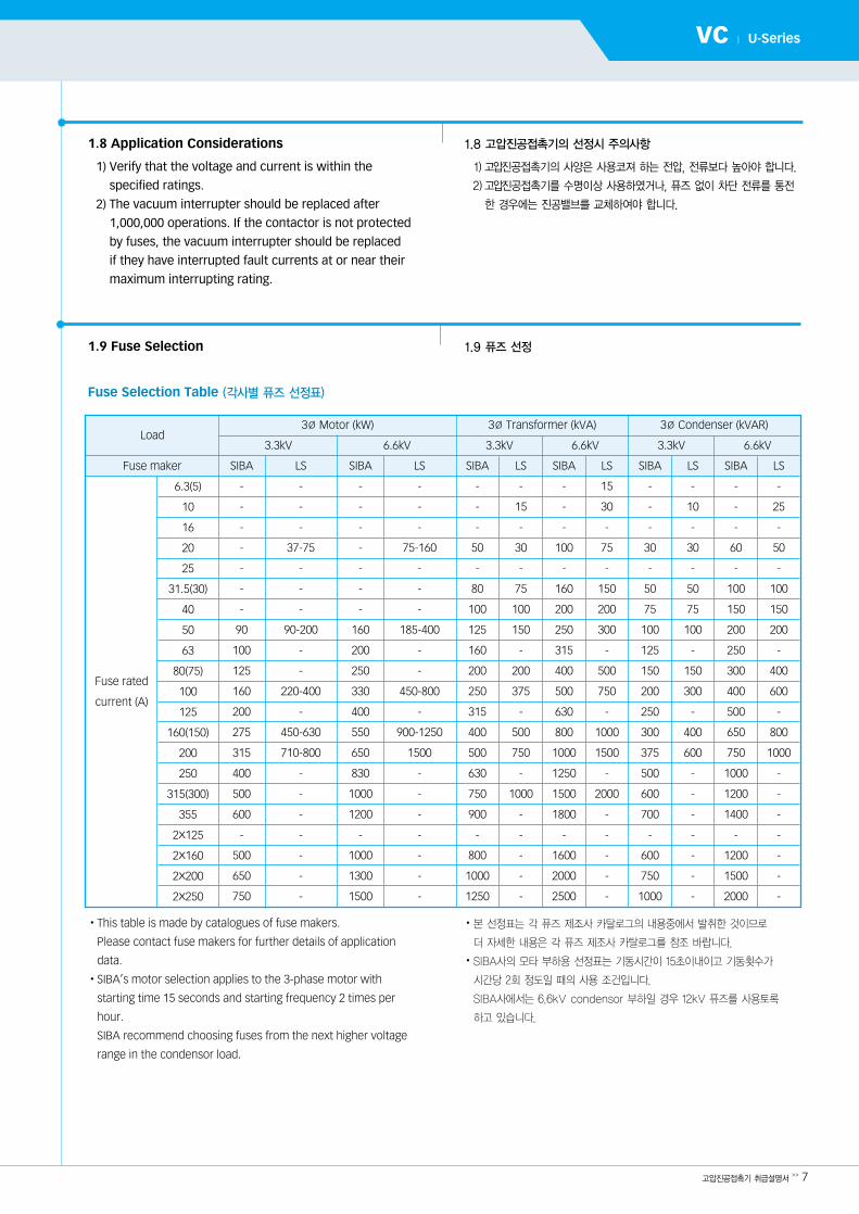
1.9 퓨즈 선정1.9 Fuse Selection
Fuse Selection Table (각사별 퓨즈 선정표)
고압진공접촉기 취급설명서>> 7
VC | U-Series
�This table is made by catalogues of fuse makers.
Please contact fuse makers for further details of application
data.
�SIBA’s motor selection applies to the 3-phase motor with
starting time 15 seconds and starting frequency 2 times per
hour.
SIBA recommend choosing fuses from the next higher voltage
range in the condensor load.
�본 선정표는 각 퓨즈 제조사 카탈로그의 내용중에서 발취한 것이므로
더 자세한 내용은 각 퓨즈 제조사 카탈로그를 참조 바랍니다.
�SIBA사의 모타 부하용 선정표는 기동시간이 15초이내이고 기동횟수가
시간당 2회 정도일 때의 사용 조건입니다.
SIBA사에서는 6.6kV condensor 부하일 경우 12kV 퓨즈를 사용토록
하고 있습니다.
3∅ Motor (kW)
3.3kV 6.6kV 3.3kV 3.3kV6.6kV 6.6kV
3∅ Transformer (kVA) 3∅ Condenser (kVAR)Load
Fuse maker
6.3(5)
10
16
20
25
31.5(30)
40
50
63
80(75)
100
125
160(150)
200
250
315(300)
355
2x125
2x160
2x200
2x250
SIBA
-
-
-
-
-
-
-
90
100
125
160
200
275
315
400
500
600
-
500
650
750
LS
-
-
-
37-75
-
-
-
90-200
-
-
220-400
-
450-630
710-800
-
-
-
-
-
-
-
LS
-
-
-
75-160
-
-
-
185-400
-
-
450-800
-
900-1250
1500
-
-
-
-
-
-
-
SIBA
-
-
-
50
-
80
100
125
160
200
250
315
400
500
630
750
900
-
800
1000
1250
LS
-
15
-
30
-
75
100
150
-
200
375
-
500
750
-
1000
-
-
-
-
-
SIBA
-
-
-
100
-
160
200
250
315
400
500
630
800
1000
1250
1500
1800
-
1600
2000
2500
LS
15
30
-
75
-
150
200
300
-
500
750
-
1000
1500
-
2000
-
-
-
-
-
SIBA
-
-
-
30
-
50
75
100
125
150
200
250
300
375
500
600
700
-
600
750
1000
LS
-
10
-
30
-
50
75
100
-
150
300
-
400
600
-
-
-
-
-
-
-
SIBA
-
-
-
60
-
100
150
200
250
300
400
500
650
750
1000
1200
1400
-
1200
1500
2000
LS
-
25
-
50
-
100
150
200
-
400
600
-
800
1000
-
-
-
-
-
-
-
SIBA
-
-
-
-
-
-
-
160
200
250
330
400
550
650
830
1000
1200
-
1000
1300
1500
Fuse rated
current (A)
1.8 고압진공접촉기의 선정시 주의사항
1)고압진공접촉기의 사양은 사용코져 하는 전압, 전류보다 높아야 합니다.
2)고압진공접촉기를 수명이상 사용하 거나, 퓨즈 없이 차단 전류를 통전
한 경우에는 진공밸브를 교체하여야 합니다.
1.8 Application Considerations
1) Verify that the voltage and current is within the
specified ratings.
2) The vacuum interrupter should be replaced after
1,000,000 operations. If the contactor is not protected
by fuses, the vacuum interrupter should be replaced
if they have interrupted fault currents at or near their
maximum interrupting rating.
8 << U-Series Vacuum Contactor Instruction Manual
U-Series Vacuum Contactors are subjected to complete
factory production tests and inspection before being
packed. They are shipped in packages designed to provide
maximum protection to the equipment during shipment
and storage.
2.1 Receiving
When contactors are delivered, receivers should examine
the contents for any signs of damage such as broken,
damage, missing, or loose components.
If damage or loss is detected, notify our nearest office or
representatives.
Inspection after unpacking
1) Check the type rating and quantities with the
specification sheet.
2) Check contactors for any damage or missing materials.
3) Check all the accessories and spares supplied.
2.2 Handling
Contactors must be handled with care to avoid damage.
Ensure that vacuum contactors do not suffer impact or
other physical stress during handling. Damage may cause
serious damage to both persons and property.
2.3 Storage
If contactors must be stored for a period prior to use, they
should be stored only in dry, dust-free, and well ventilated
rooms, with contactors in the open condition.
U-Series 고압진공접촉기는 공장에서 제조된 후, 포장되기전
시험 및 검사를 시행하 습니다.
이 제품은 운송 및 보관 중에 파손되지 않도록 포장되어 운반됩니다.
2.1 인수
고압진공접촉기를 처음 인수할 때는, 운반도중 제품의 파손, 손상 및 결여된
부품 등이 있는지 검사하여 주십시오.
어떤 하자를 발견하 을 시, 즉시 가까운 업이나 지사로 연락하시기
바랍니다.
제품 인수후 다음 사항을 점검하십시오.
1)정격 사양과 수량
2)제품 파손이나 누락 자재 여부
3)부속품이나 예비품의 파손이나 누락 여부
2.2 취급
고압진공접촉기에 파손 및 손상이 입지 않도록 주의해서 취급하십시오.
취급 도중, 제품에 충격을 가하지 마십시오. 제품에 가해진 충격은 특성이나
안전에 심각한 손상을 입힐 수 있습니다.
2.3 보관
고압진공접촉기 인수 후, 곧바로 설치되지 않는다면, 먼지가 없고, 습기가
적으며 통풍이 잘되는 곳에 open 상태로 보관하십시오.
Concrete dust or any other dustshould not be inside the product when it installed.
It can cause fire or misoperation.
먼지, 콘크리트 가루, 철분 등의 미물질 및 빗물
등이 본제품의 내부에 들어가지 않도록
보관하십시오.
화재, 동작 불량이 발생할 수 있습니다.
Excessive weight can cause seriousinjury or damage.
To avoid this situation, Do NOT transport a contactor on a lifting facility in the raised position.
제품 이동시 낙하로 인한 심각한 사고 및 제품
손상이 우려됩니다.
이를 방지하기 위해서는 운반 장치로 제품 이동시
높이 올려진 상태로 이동하지 마십시오.
Receiving / Handling / Storage and Installation 인수 / 취급 / 보관 및 설치02

고압진공접촉기 취급설명서>> 9
VC | U-Series
2.4 Installation
1) Confirm the type and rating, check for damage,
and clean contactors with a dry cloth, before installing
contactors into the switchgear.
2) Mount contactors on a level floor referring to
guidelines for mounting dimensions in our catalogue
“U-Series Vacuum Contactor”.
3) Clean the connecting surface with a dry cloth, and then
connect main-circuit buses and earth terminals.
Be careful not to shock enclosures and contactors.
2.5 Inspection Before Operation
1) Confirm contactors are installed properly.
If not, install contactors again according to clause 2.4.
2) Operate contactors a few times manually to ensure
that contactors close and open smoothly.
Then, operate contactors electrically in the test
position, and confirm that the ON/OFF indicator works
properly.
3) Confirm that no tools and materials are left near the
contactor.
2.4 설치 작업
1)고압진공접촉기를 배전반에 설치하기 전 접촉기의 Type, 정격 및
손상여부를 재확인하고, 마른걸레로 먼지 및 더러운 부분을
닦아냅니다.
2)수평편차가 1mm 이내가 되도록 설치되어야 하며, 설치 관련 치수는
U-Series 고압진공접촉기 카탈로그를 참조바랍니다.
3)연결 부위를 깨끗이 닦아낸후 연결 및 접지 작업을 하여, 작업시
제품에 무리한 힘이 걸리지 않도록 주의하십시오.
2.5 운전 전 점검사항
1)결선이 정확한지 확인하고, 설치시 볼트 및 너트가 제 로 조여졌는지
확인하십시오.
2)수동으로 개폐조작을 하여 동작의 이상유무와 ON/OFF 지시창의
동작을 확인하십시오.
시험위치에서 전기적으로 동작의 이상유무를 확인하십시오.
3)고압진공접촉기 주위에 작업 공구가 남아 있는지를 확인하십시오.
�Do not work on contactors unless theprimary circuit is disconnected by the visible breaker.
�When connecting bus-bars, tighten boltsby our standard.
�Contactors are mounted on the verticalor horizontal plane tightly.
�설치에 앞서 모든 전원을 차단하기 위해 앞단의
차단기나 그러한 종류의 제품을 반드시 open
시켜 주십시오.
감전의 위험이 있습니다.
�단자 bolt는 표준체결 torque로 확실하게 조여
주십시오. 화재의 위험이 있습니다.
�본 제품은 평탄한 수평 또는 수직면에
단단하게 취부하여 고정시켜 주십시오.
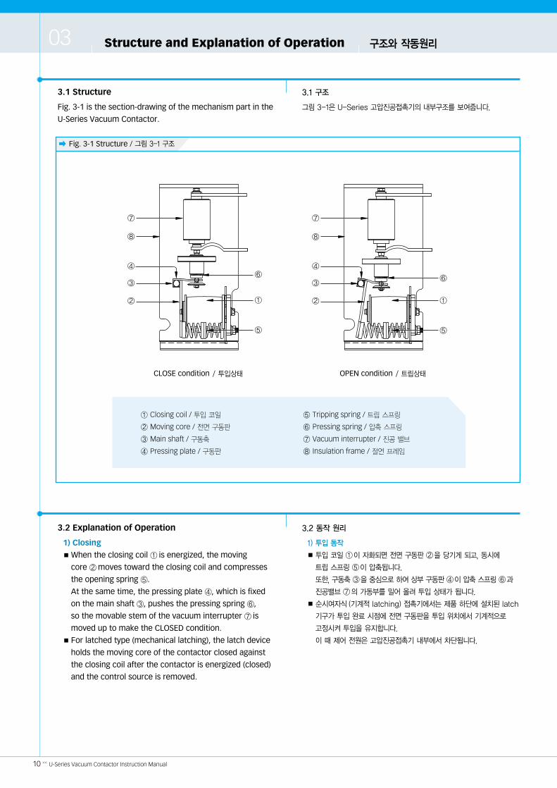
� Fig. 3-1 Structure / 그림 3-1 구조
10 << U-Series Vacuum Contactor Instruction Manual
3.1 Structure
Fig. 3-1 is the section-drawing of the mechanism part in the
U-Series Vacuum Contactor.
3.2 Explanation of Operation
1) Closing■ When the closing coil ① is energized, the moving
core ②moves toward the closing coil and compresses
the opening spring ⑤.
At the same time, the pressing plate ④, which is fixed
on the main shaft ③, pushes the pressing spring ⑥,
so the movable stem of the vacuum interrupter ⑦ is
moved up to make the CLOSED condition.■ For latched type (mechanical latching), the latch device
holds the moving core of the contactor closed against
the closing coil after the contactor is energized (closed)
and the control source is removed.
3.1 구조
그림 3-1은 U-Series 고압진공접촉기의 내부구조를 보여줍니다.
3.2 동작 원리
1) 투입 동작
■투입 코일 ①이 자화되면 전면 구동판 ②을 당기게 되고, 동시에
트립 스프링 ⑤이 압축됩니다.
또한, 구동축③을중심으로하여상부구동판④이압축스프링⑥과
진공밸브 ⑦의 가동부를 어 올려 투입 상태가 됩니다.
■순시여자식(기계적 latching) 접촉기에서는 제품 하단에 설치된 latch
기구가 투입 완료 시점에 전면 구동판을 투입 위치에서 기계적으로
고정시켜 투입을 유지합니다.
이 때 제어 전원은 고압진공접촉기 내부에서 차단됩니다.
⑦
⑧
④
③
② ①
⑤
⑥
⑦
⑧
④
③
② ①
⑤
⑥
Structure and Explanation of Operation 구조와 작동원리03
CLOSE condition / 투입상태 OPEN condition / 트립상태
① Closing coil / 투입 코일
② Moving core / 전면 구동판
③ Main shaft / 구동축
④ Pressing plate / 구동판
⑤ Tripping spring / 트립 스프링
⑥ Pressing spring / 압축 스프링
⑦ Vacuum interrupter / 진공 밸브
⑧ Insulation frame / 절연 프레임
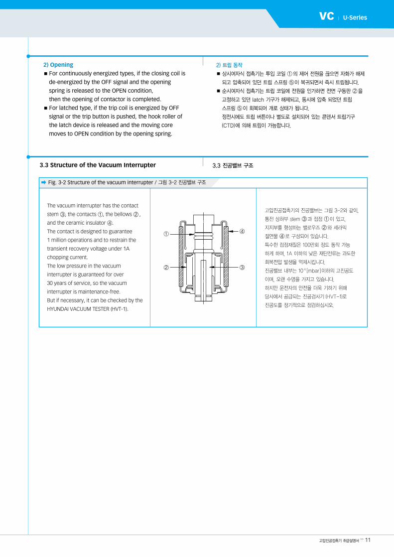
� Fig. 3-2 Structure of the vacuum interrupter / 그림 3-2 진공밸브 구조
고압진공접촉기 취급설명서>> 11
VC | U-Series
2) Opening■ For continuously energized types, if the closing coil is
de-energized by the OFF signal and the opening
spring is released to the OPEN condition,
then the opening of contactor is completed. ■ For latched type, if the trip coil is energized by OFF
signal or the trip button is pushed, the hook roller of
the latch device is released and the moving core
moves to OPEN condition by the opening spring.
3.3 Structure of the Vacuum Interrupter
2) 트립 동작
■상시여자식 접촉기는 투입 코일 ①의 제어 전원을 끊으면 자화가 해제
되고 압축되어 있던 트립 스프링 ⑤이 복귀되면서 즉시 트립됩니다.
■순시여자식 접촉기는 트립 코일에 전원을 인가하면 전면 구동판 ②을
고정하고 있던 latch 기구가 해제되고, 동시에 압축 되었던 트립
스프링 ⑤이 회복되어 개로 상태가 됩니다.
정전시에도 트립 버튼이나 별도로 설치되어 있는 콘덴서 트립기구
(CTD)에 의해 트립이 가능합니다.
3.3 진공밸브 구조
①
②
④
③
고압진공접촉기의 진공밸브는 그림 3-2와 같이,
통전 상하부 stem ③과 접점 ①이 있고,
지지부를 형성하는 밸로우즈 ②와 세라믹
절연물 ④로 구성되어 있습니다.
특수한 접점재질은 100만회 정도 동작 가능
하게 하며, 1A 이하의 낮은 재단전류는 과도한
회복전압 발생을 억제시킵니다.
진공밸브 내부는 10-6 [mbar]이하의 고진공도
이며, 오랜 수명을 가지고 있습니다.
하지만 운전자의 안전을 더욱 기하기 위해
당사에서 공급되는 진공검사기(HVT-1)로
진공도를 정기적으로 점검하십시오.
The vacuum interrupter has the contact
stem ③, the contacts ①, the bellows ② ,
and the ceramic insulator ④.
The contact is designed to guarantee
1 million operations and to restrain the
transient recovery voltage under 1A
chopping current.
The low pressure in the vacuum
interrupter is guaranteed for over
30 years of service, so the vacuum
interrupter is maintenance-free.
But if necessary, it can be checked by the
HYUNDAI VACUUM TESTER (HVT-1).
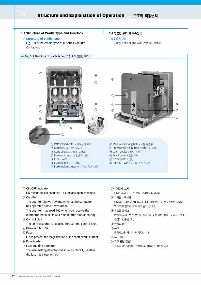
� Fig. 3-3 Structure of cradle type / 그림 3-3 인출형 구조
12 << U-Series Vacuum Contactor Instruction Manual
3.4 Structure of Cradle Type and Interlock
1) Structure of cradle type
Fig. 3-3 is the cradle type of U-Series Vacuum
Contactor.
① ON/OFF indicator
ON means closed condition, OFF means open condition.
② Counter
The counter shows how many times the contactor
has operated since it was made.
The counter may read 100 when you receive the
contactor, because it was tested after manufacturing.
③ Control plug
The control source is supplied through the control Jack.
④ Draw-out button
⑤ Fuse
Fuses prevent the magnification of the short-circuit current.
⑥ Fuse holder
⑦ Fuse melting detector
The fuse melting detector can show electrically whether
the fuse has blown or not.
3.4 인출형 구조 및 구속장치
1) 인출형 구조
인출형은 그림 3-3과 같이 구성되어 있습니다.
① 개폐상태 표시기
ON은 투입, OFF는 트립 상태를 나타냅니다.
② 개폐횟수 표시기
ON/OFF 개폐횟수를 표시합니다. 제품 생산 후 성능 시험에 의하여
약 100회 정도로 개폐 되어 출고 됩니다.
③ 콘트롤 플러그
21개의 pin이 있는 콘트롤 플러그를 통해 제어전원이 공급되고 보조
접점이 검출됩니다.
④ 인출입 버튼
⑤ 퓨즈
단락사고를 막기 위한 장치입니다.
⑥ 퓨즈 홀더
⑦ 퓨즈 용단 검출기
퓨즈의 용단여부를 전기적으로 검출하는 장치입니다.
③
⑨
④
⑨
⑦
⑥
⑧
②
①①
②
④
⑤
⑫
⑪
① ON/OFF indicator / 개폐상태 표시기
② Counter / 개폐횟수 표시기
③ Control plug / 콘트롤 플러그
④ Draw-out button / 인출입 버튼
⑤ Fuse / 퓨즈
⑥ Fuse holder / 퓨즈 홀더
⑦ Fuse melting detector / 퓨즈 용단 검출기
⑧ Manual checking hole / 수동 점검구
⑨ Emergency trip button / 비상 트립 버튼
⑩ Latch device / 트립 장치
⑪ Front cover / 전면 커버
⑫ Name plate / 명판
⑬ Position switch / 위치 검출 스위치
Structure and Explanation of Operation 구조와 작동원리03
③
⑩
⑬
고압진공접촉기 취급설명서>> 13
VC | U-Series
⑧ Manual checking hole
A manual checking hole is used to close the contactor
manually.
⑨ Emergency trip button
Only the latched types have the trip button which is
used in emergencies.
⑩ Latch device
⑪ Front cover
⑫ Name plate
⑬ Position switch
The position switch indicates electrically whether the
contactor is in the TEST or CONNECTION position.
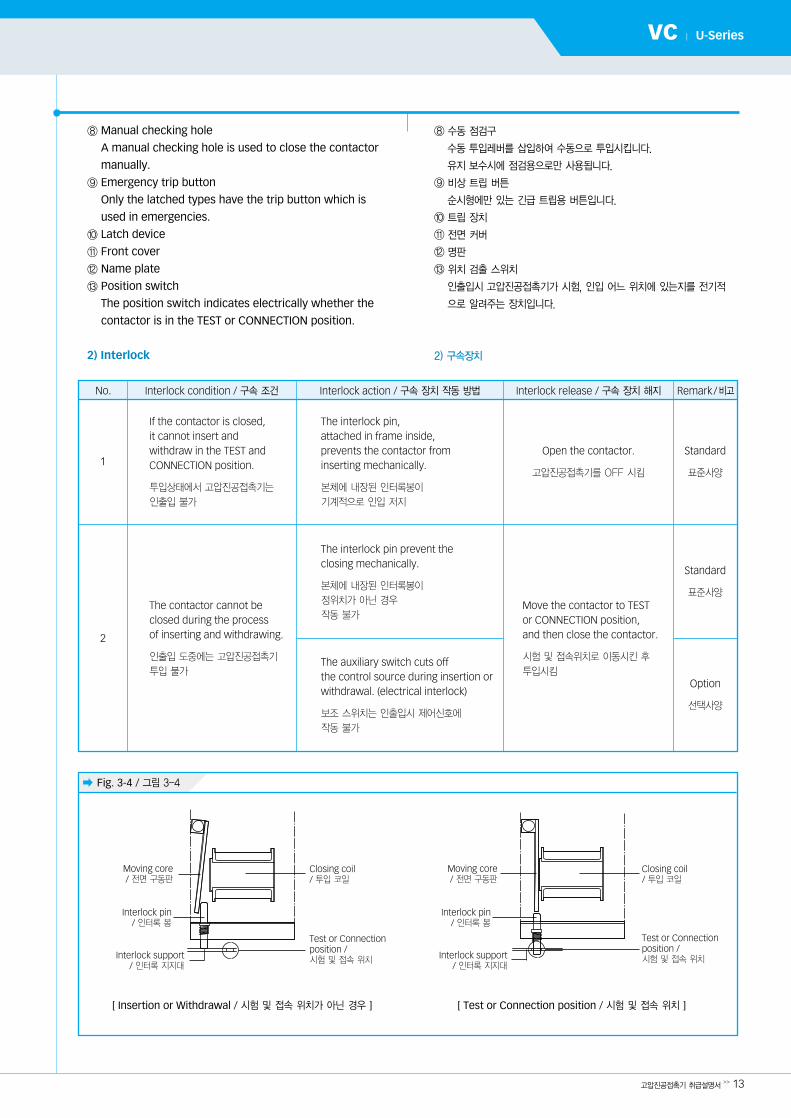
2) Interlock
⑧ 수동 점검구
수동 투입레버를 삽입하여 수동으로 투입시킵니다.
유지 보수시에 점검용으로만 사용됩니다.
⑨ 비상 트립 버튼
순시형에만 있는 긴급 트립용 버튼입니다.
⑩ 트립 장치
⑪ 전면 커버
⑫ 명판
⑬ 위치 검출 스위치
인출입시 고압진공접촉기가 시험, 인입 어느 위치에 있는지를 전기적
으로 알려주는 장치입니다.
2) 구속장치
No. Interlock condition / 구속 조건 Interlock action / 구속 장치 작동 방법 Interlock release / 구속 장치 해지 Remark/비고
1
2
If the contactor is closed, it cannot insert and withdraw in the TEST and CONNECTION position.
투입상태에서 고압진공접촉기는
인출입 불가
The contactor cannot be closed during the process of inserting and withdrawing.
인출입 도중에는 고압진공접촉기
투입 불가
Move the contactor to TEST or CONNECTION position, and then close the contactor.
시험 및 접속위치로 이동시킨 후
투입시킴
The interlock pin, attached in frame inside, prevents the contactor from inserting mechanically.
본체에 내장된 인터록봉이
기계적으로 인입 저지
The interlock pin prevent the closing mechanically.
본체에 내장된 인터록봉이
정위치가 아닌 경우
작동 불가
The auxiliary switch cuts off the control source during insertion orwithdrawal. (electrical interlock)
보조 스위치는 인출입시 제어신호에
작동 불가
Open the contactor.
고압진공접촉기를 OFF 시킴
Standard
표준사양
Standard
표준사양
Option
선택사양
� Fig. 3-4 / 그림 3-4
Moving core / 전면 구동판
Interlock pin/ 인터록 봉
Interlock support/ 인터록 지지
Test or Connectionposition / 시험 및 접속 위치
Closing coil/ 투입 코일
Moving core / 전면 구동판
Interlock pin/ 인터록 봉
Interlock support/ 인터록 지지
Test or Connectionposition / 시험 및 접속 위치
Closing coil/ 투입 코일
[ Insertion or Withdrawal / 시험 및 접속 위치가 아닌 경우 ] [ Test or Connection position / 시험 및 접속 위치 ]
� Fig. 3-5 / 그림 3-5
14 << U-Series Vacuum Contactor Instruction Manual
Structure and Explanation of Operation 구조와 작동원리03
3.5 Inserting & Withdrawing
1) How to insert the contactor in the E, F cradle.
■ Inserting
Set the wheels of the contactor
exactly on the guide rail of the cradle.
The lifter should be used when the
contactor is lifted in order to
install it into switchgears.
When the contactor reaches to the
TEST position, the interlock pin
prevents the draw-in at this position.
Push the draw-out button (Fig. 3-5)
and then insert the contactor to
the CONNECTION position. If the
contactor is in the correct position,
the interlock pin is in the hole on
the interlock support and the
female contact will be inserted
fully into the terminal.
■ Withdrawing
When a contactor is withdrawn, the contactor cannot
be operated because of the interlock.
In OPEN condition, push the draw-out button
(Fig. 3-5) and pull out a contactor to the TEST position.
3.5 인출입 방법
1) E& F cradle 인출입 방법
■인입
크레들 레일위에 고압진공접촉기를 정확하게
올려놓아 주십시오.
이때 안전을 위해서 반드시 Lift를 이용하여
접촉기를 들어올리십시오.
접촉기를 수평으로 어 넣으면 인출입 버튼에
연결된 인터록 봉이 Test 위치 구멍에 걸려
더 이상 인입되지 않게 됩니다.
이 위치에서는 제어전원을 연결하여 필요시
내부회로를 시험할 수 있습니다.
접속 위치로 삽입하기 위해서는 인출입 버튼을
다시 누르고 어 넣습니다.
인입이 완료되면 Isolation Contact가
Terminal에 충분히 삽입되고 접속위치 구멍에
인터록 봉이 들어가면서 구속됩니다.
■인출
인출 도중에는 고압진공접촉기가 동작 할 수 없습니다.
Cradle으로부터 분리하고자 할 때는, 트립상태에서
인출입 버튼을 누른 다음 고압진공접촉기를 당기면 됩니다.
Do not touch the primary circuit. �통전되는 전원부에는 손 지 마십시오.
�감전에 의한 제품 손상이나 인명사고가 발생할
수 있습니다.
�Do not insert and withdraw the contactor in the closed condition.
�인출입은 반듯이 고압진공접촉기를 open시킨후
행하여 주십시오.
심각한 사고 및 제품 손상의 위험이 있습니다.
�제품을 인출입 중간에 놓아두지 마십시오.
항상 시험 또는 접속 위치에 있도록 하십시오.
�Do not leave contactors in intermediateposition. Always place the contactors intest or connection position.
Draw-out button/ 인출입 버튼
Interlock release bar/ 인터록 해제 봉
고압진공접촉기 취급설명서>> 15
VC | U-Series
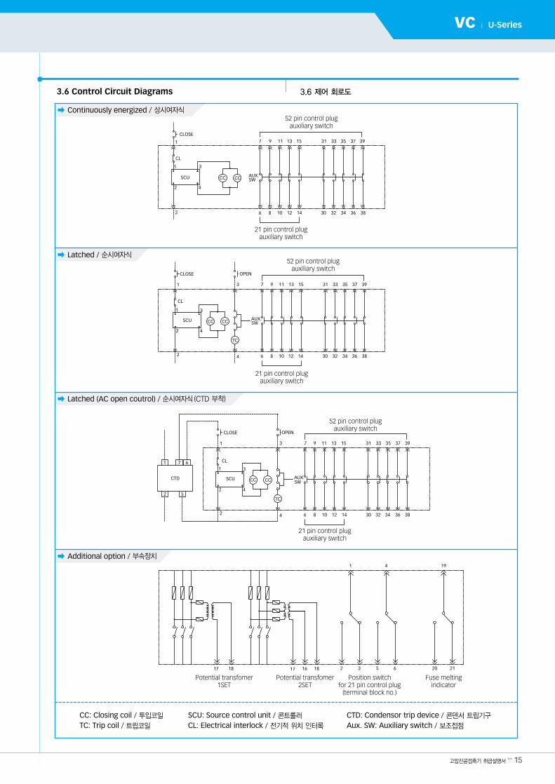
� Continuously energized / 상시여자식
� Latched / 순시여자식
� Latched (AC open coutrol) / 순시여자식(CTD 부착)
� Additional option / 부속장치
3.6 Control Circuit Diagrams 3.6 제어 회로도
CC: Closing coil / 투입코일
TC: Trip coil / 트립코일
SCU: Source control unit / 콘트롤러
CL: Electrical interlock / 전기적 위치 인터록
CTD: Condensor trip device / 콘덴서 트립기구
Aux. SW: Auxiliary switch / 보조접점
52 pin control plugauxiliary switch
52 pin control plugauxiliary switch
52 pin control plugauxiliary switch
21 pin control plugauxiliary switch
21 pin control plugauxiliary switch
21 pin control plugauxiliary switch
Potential transfomer1SET
Potential transfomer2SET
Position switchfor 21 pin control plug
(terminal block no.)
Fuse melting indicator
� Table 4-1 / 표 4-1
16 << U-Series Vacuum Contactor Instruction Manual
Inspection and Maintenance 검사와 유지보수04
Maintenance shall be carried out to preserve trouble-free
operation and achieve the longest possible working life of
the contactors.
U-Series Vacuum Contactors are characterized by their
simple and robust construction and they have a long life
expectancy. Their operating mechanisms have a low
maintenance requirement, and the interrupters are
maintenance-free during their working life.
The maintenance is determined by environmental
influences, switching frequency, and so on.
4.1 Visual Inspection (every 1-6 months)
The purpose of a visual inspection has to be done
whenever you can.
고압진공접촉기의 보수는 오작동을 방지하며, 오랜 기간 동안 작동시키기
위해 필요합니다.
U-Series 고압진공접촉기는 견고한 구조 및 유지�보수가 간단하게 되어
있으며 오랜 수명을 가지는 것이 특징입니다.
기계장치는 간단한 유지보수를 필요로 하며, 진공밸브는 수명기간이
되기 전까지 보수가 거의 필요 없습니다.
유지보수는 고압진공접촉기의 주위환경, 동작횟수에 의해 조금씩 차이가
있습니다.
4.1 일상 점검(매 1~6개월)
일상 점검은 가능한 자주 하는 것이 좋습니다.
고압진공접촉기가 비정상적인 작동을 하거나, 성능에 이상이 있는 경우
당사로 신속히 연락하여 점검을 받으시기 바랍니다.
No. Items / 점검사항 Procedure of checking / 점검 방법
1
2
3
ON/OFF indicator
Abnormal smell / 소음이나 냄새
Damage / 손상
Check if each state of ON/OFF is identified accurately.투입시 ON, 트립시 OFF의 표시가 정확한지 확인 합니다.
Check if the closing coil is overheated or burned.비정상적인 소음이나 냄새가 나는지 확인 합니다.
Check for cracks, breaks, and discoloration.균열, 파손이나 변색이 있는지 확인 합니다.
�Failure to maintain the equipment could result in serious injury and productfailure and can prevent successfulfunctioning of connected apparatus.
�Do not work on contactors with power being supplied to the control circuit.
�Do not leave maintenance tools near the contactor.
�Do not work on closed contactors.�Be sure that bolts are tightened by
our standard after replacement and check the tightness regularly.
�잘못된 유지 보수 작업은 심각한 사고 및 제품의
손상을 발생하거나 혹은 부하의 정상적인
작동을 방해할 수 있습니다.
�유지 보수 작업을 할 경우 반드시 앞단의
제어회로 차단기를 open시키고 콘트롤 플러그를
뽑아 접촉기의 제어전원을 차단하도록 하십시오.
�유지 보수 작업후 공구가 접촉기 주위에 남아
있지 않도록 하십시오.
�내부 점검은 본 제품이 open 상태인 것을 확인
한 후 행하십시오. close 상태에서 점검 중
open이 될 경우 손가락 및 공구가 기구부에
끼여 다칠 위험이 있습니다.
�단자 볼트는 정기적으로 표준 체결 torque로
조여 주십시오.
볼트 풀림은 화재 발생의 원인이 됩니다.
고압진공접촉기 취급설명서>> 17
VC | U-Series
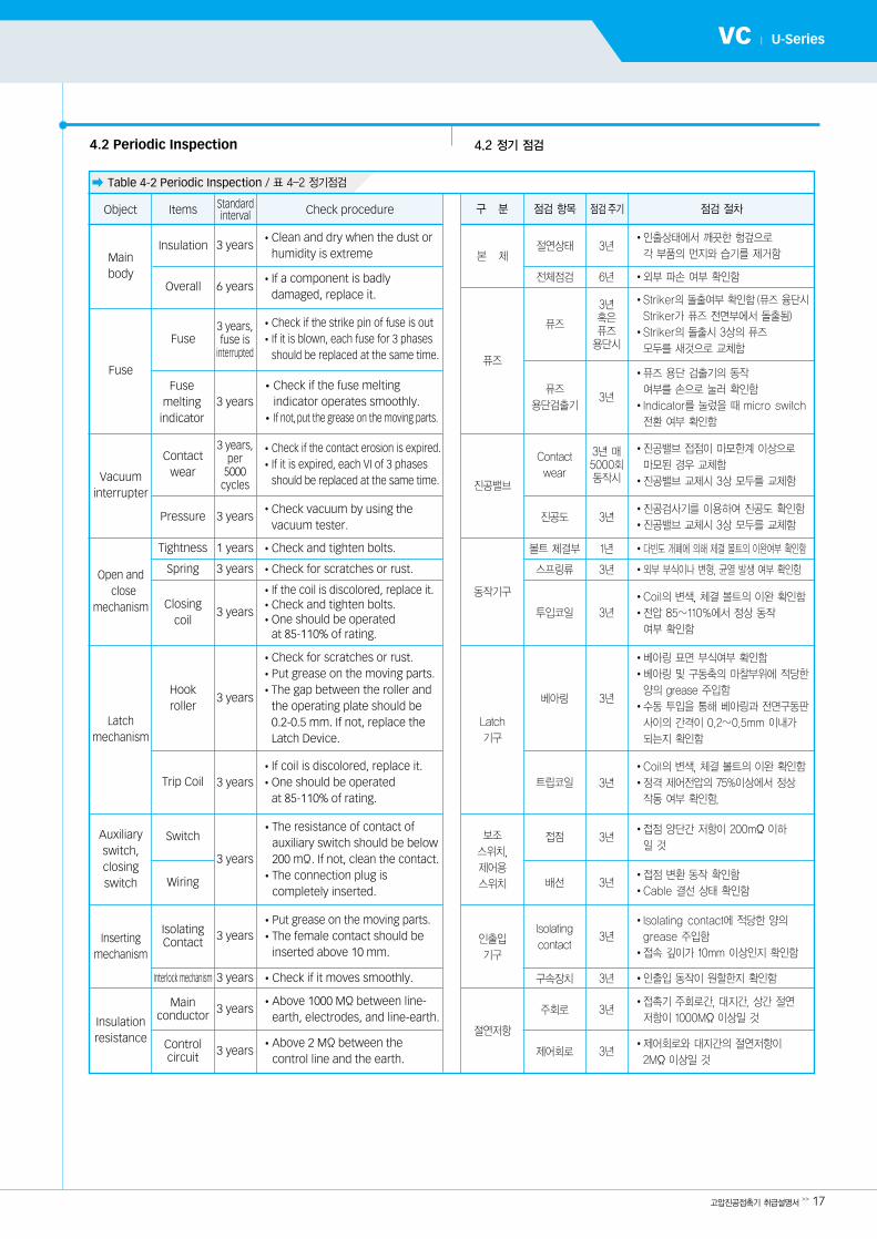
� Table 4-2 Periodic Inspection / 표 4-2 정기점검
구 분 점검 항목 점검주기 점검 절차
�인출상태에서 깨끗한 헝겊으로
각 부품의 먼지와 습기를 제거함
�외부 파손 여부 확인함
�진공밸브 접점이 마모한계 이상으로
마모된 경우 교체함
�진공밸브 교체시 3상 모두를 교체함
�진공검사기를 이용하여 진공도 확인함
�진공밸브 교체시 3상 모두를 교체함
�다빈도 개폐에 의해 체결 볼트의 이완여부 확인함
�외부 부식이나 변형, 균열 발생 여부 확인함
�Coil의 변색, 체결 볼트의 이완 확인함
�전압 85�110%에서 정상 동작
여부 확인함
�베아링 표면 부식여부 확인함
�베아링 및 구동축의 마찰부위에 적당한
양의 grease 주입함
�수동 투입을 통해 베아링과 전면구동판
사이의 간격이 0.2�0.5mm 이내가
되는지 확인함
�Coil의 변색, 체결 볼트의 이완 확인함
�정격 제어전압의 75%이상에서 정상
작동 여부 확인함.
�접점 변환 동작 확인함
�Cable 결선 상태 확인함
�인출입 동작이 원할한지 확인함
�접촉기 주회로간, 지간, 상간 절연
저항이 1000MΪ이상일 것
본 체
진공밸브
동작기구
Latch
기구
보조
스위치,
제어용
스위치
인출입
기구
절연저항
Contact
wear
진공도
볼트 체결부
스프링류
투입코일
베아링
트립코일
접점
배선
Isolating
contact
구속장치
주회로
제어회로
3년 매5000회동작시
3년
1년
3년
3년
3년
3년
3년
3년
3년
3년
3년
3년
절연상태 3년
6년전체점검
Object Items Standardinterval Check procedure
Fuse
Vacuuminterrupter
Open andclose
mechanism
Latch mechanism
Insertingmechanism
Insulation resistance
Contactwear
Pressure
Tightness
Spring
Trip Coil
Switch
Wiring
IsolatingContact
Interlock mechanism
Main conductor
Controlcircuit
3 years,per
5000cycles
3 years
1 years
3 years
3 years
3 years
3 years
3 years
3 years
3 years
3 years
3 years
6 years
3 years,fuse is
interrupted
Overall
Fuse
4.2 Periodic Inspection 4.2 정기 점검
Insulation 3 yearsMain body
3 yearsFuse
meltingindicator
�Check vacuum by using thevacuum tester.
�Check if the fuse melting indicator operates smoothly.
�If not,put the grease on the moving parts.
�Check and tighten bolts.
�Check for scratches or rust.
�If coil is discolored, replace it.�One should be operated
at 85-110% of rating.
�Check if it moves smoothly.
3년혹은퓨즈용단시
3년
퓨즈
퓨즈
용단검출기
퓨즈�퓨즈 용단 검출기의 동작
여부를 손으로 눌러 확인함
�Indicator를 눌 을 때 micro switch
전환 여부 확인함
�Striker의 돌출여부 확인함(퓨즈 융단시
Striker가 퓨즈 전면부에서 돌출됨)
�Striker의 돌출시 3상의 퓨즈
모두를 새것으로 교체함
Closingcoil
Hook roller
Auxiliary switch,closingswitch
�제어회로와 지간의 절연저항이
2MΪ이상일 것
�Isolating contact에 적당한 양의
grease 주입함
�접속 깊이가 10mm 이상인지 확인함
�접점 양단간 저항이 200mΪ이하
일 것
�The resistance of contact ofauxiliary switch should be below200 mΪ. If not, clean the contact.
�The connection plug iscompletely inserted.
�Above 2 MΪbetween the control line and the earth.
�Above 1000 MΪbetween line-earth, electrodes, and line-earth.
�Put grease on the moving parts.�The female contact should be
inserted above 10 mm.
�Check for scratches or rust.�Put grease on the moving parts. �The gap between the roller and
the operating plate should be0.2-0.5 mm. If not, replace theLatch Device.
�Check if the contact erosion is expired.�If it is expired, each VI of 3 phases
should be replaced at the same time.
�Check if the strike pin of fuse is out�If it is blown, each fuse for 3 phases
should be replaced at the same time.
�If a component is badlydamaged, replace it.
�Clean and dry when the dust orhumidity is extreme
�If the coil is discolored, replace it.�Check and tighten bolts.�One should be operated
at 85-110% of rating.

� Fig. 4-1 Checking the contact erosion / 그림 4-1 진공밸브의 마모 확인
18 << U-Series Vacuum Contactor Instruction Manual
Inspection and Maintenance 검사와 유지보수04
4.3 Checking Vacuum and the Contact Erosion Limit
1) Checking the vacuum
The low pressure in the vacuum interrupter is
guaranteed for over 30 years of service.
That means the vacuum interrupter is maintenance-free.
But if necessary, it can be checked by the
HYUNDAI VACUUM TESTER (HVT-1).
2) Checking the contact erosion
Since the contacts are contained inside the interrupter,
they remain clean and require no maintenance.
However, during high current interrupting, there may
be a minimum amount of erosion from the contact
surfaces. To check the erosion of the interrupter
contacts and carry out the following operations.■ Close the contactor.■ Open the rear cover (if the contactor has a rear cover). ■ Measure the distance between the dish washer
and the pressing plate.
With new interrupters this distance is about
1.2-1.5 mm.
If it is reduced to 0.5 mm, the three interrupters
must be replaced.
Checking the contact erosion is important to
evaluate the efficiency of the interrupters.
(refer to the Fig. 4-1)
4.3 진공밸브의 진공상태와 마모 확인
1) 진공상태 점검
고압진공접촉기는 진공의 우수한 절연내력에 의해 성능이 유지되고
있으므로 진공도의 유지가 매우 중요합니다. 진공밸브의 진공도가
pachen의 절연 내력 임계치(1×10⁻³ mbar)이하로 떨어지는 경우,
차단 및 개폐능력이 저하될 수 있으므로, 정기점검시 혹은 매 3년
주기로 진공검사기를 사용하여 진공도를 확인하여 주시는 것이
안전합니다.
진공검사기로 동상 주회로 단자간에 전압을 인가하여 meter 및
lamp에 의해 즉시 양부상태에 한 판정이 가능합니다.
(보다 상세한 내용은 별도의 진공 검사기 설명서를 참고하세요.)
2) 진공밸브의 마모 확인
접점이 진공밸브 안에 있어 깨끗하게 유지되므로 보수가 필요하지
않지만, 차단기에 높은 전류가 흐를 때 접점표면에서 소량의 마모가
생길 수 있습니다.
다음의 순서에 따라 접점 마모량을 측정하십시오.
■ 접촉기를 투입 시킵니다.
■ 후면판을 풀어냅니다. (있는 경우)
■ Dish washer와 가압판 사이의 간격(=wipe)을 측정합니다.
신품의 경우 이 간격은 1.2~1.5mm입니다.
만약 wipe가 0.5mm 이하가 되면 반드시 3상의 진공밸브를
모두 교체하여야 합니다. (그림 4-1 참조)
접점 마모량 관리는 접촉기 성능 유지에 매우 중요합니다.
�Replace the vacuum interrupter when the wipe is below 0.5 mm.
�Wipe가 0.5mm 이하가 되면 진공 밸브를 교체
하여 주십시오.
접점 마모가 과도한 경우 통전 불량 및 제품
손상이 발생 할 수 있습니다.
1.2-1.5 mm 0.5 mm
Dish washer
Pressing plate
고압진공접촉기 취급설명서>> 19
VC | U-Series
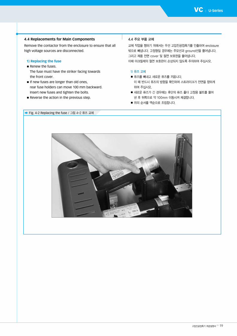
4.4 Replacements for Main Components
Remove the contactor from the enclosure to ensure that all
high voltage sources are disconnected.
1) Replacing the fuse■ Renew the fuses.
The fuse must have the striker facing towards
the front cover.■ If new fuses are longer than old ones,
rear fuse holders can move 100 mm backward.
Insert new fuses and tighten the bolts.■ Reverse the action in the previous step.
4.4 주요 부품 교체
교체 작업을 행하기 위해서는 우선 고압진공접촉기를 인출하여 enclosure
밖으로 빼냅니다. 고정형일 경우에는 주모선과 ground선을 풀어냅니다.
그리고 제품 전면 cover 및 절연 보호판을 풀어냅니다.
이때 아크릴제의 절연 보호판이 손상되지 않도록 주의하여 주십시오.
1) 퓨즈 교체
■퓨즈를 빼내고 새로운 퓨즈를 끼웁니다.
이 때 반드시 퓨즈의 방향을 확인하여 스트라이크가 전면을 향하게
하여 주십시오.
■새로운 퓨즈가 긴 경우에는 후단의 퓨즈 홀더 고정용 볼트를 풀어
낸 후 뒤쪽으로 약 100mm 이동시켜 체결합니다.
■위의 순서를 역순으로 조립합니다.
� Fig. 4-2 Replacing the fuse / 그림 4-2 퓨즈 교체
� Fig. 4-4 / 그림 4-4
� Fig. 4-3 / 그림 4-3
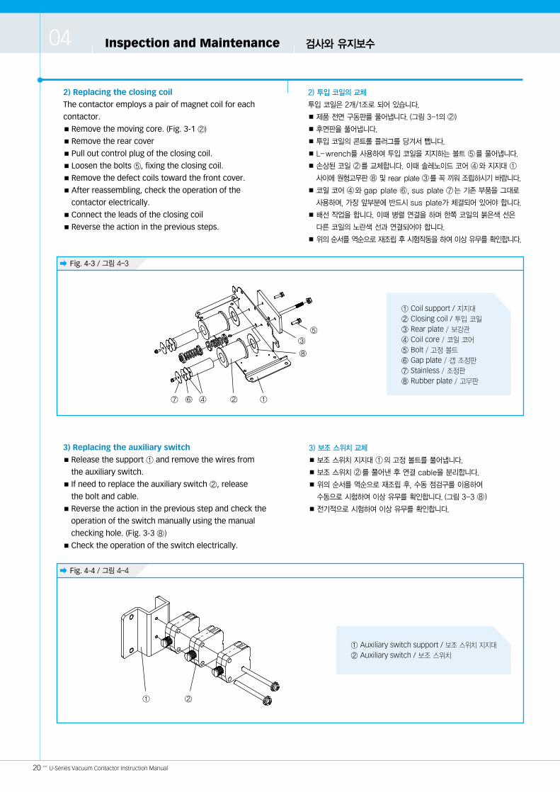
2) Replacing the closing coil
The contactor employs a pair of magnet coil for each
contactor.■ Remove the moving core. (Fig. 3-1 ②)
■ Remove the rear cover■ Pull out control plug of the closing coil.■ Loosen the bolts ⑤, fixing the closing coil.■ Remove the defect coils toward the front cover. ■ After reassembling, check the operation of the
contactor electrically.■ Connect the leads of the closing coil■ Reverse the action in the previous steps.
2) 투입 코일의 교체
투입 코일은 2개/1조로 되어 있습니다.
■제품 전면 구동판를 풀어냅니다. (그림 3-1의 ②)
■후면판을 풀어냅니다.
■투입 코일의 콘트롤 플러그를 당겨서 뺍니다.
■ L-wrench를 사용하여 투입 코일을 지지하는 볼트 ⑤를 풀어냅니다.
■손상된 코일 ②를 교체합니다. 이때 솔레노이드 코어 ④와 지지 ①
사이에원형고무판⑧ 및 rear plate ③를꼭끼워조립하시기바랍니다.
■코일 코어 ④와 gap plate ⑥, sus plate ⑦는 기존 부품을 그 로
사용하며, 가장 앞부분에 반드시 sus plate가 체결되어 있어야 합니다.
■배선 작업을 합니다. 이때 병렬 연결을 하며 한쪽 코일의 붉은색 선은
다른 코일의 노란색 선과 연결되어야 합니다.
■위의순서를역순으로재조립후시험작동을하여이상유무를확인합니다.
20 << U-Series Vacuum Contactor Instruction Manual
Inspection and Maintenance 검사와 유지보수04
3) 보조 스위치 교체
■보조 스위치 지지 ①의 고정 볼트를 풀어냅니다.
■보조 스위치 ②를 풀어낸 후 연결 cable을 분리합니다.
■위의 순서를 역순으로 재조립 후, 수동 점검구를 이용하여
수동으로 시험하여 이상 유무를 확인합니다. (그림 3-3 ⑧)
■전기적으로 시험하여 이상 유무를 확인합니다.
3) Replacing the auxiliary switch ■ Release the support ① and remove the wires from
the auxiliary switch. ■ If need to replace the auxiliary switch ②, release
the bolt and cable.■ Reverse the action in the previous step and check the
operation of the switch manually using the manual
checking hole. (Fig. 3-3 ⑧)
■ Check the operation of the switch electrically.
① Coil support / 지지
② Closing coil / 투입 코일
③ Rear plate / 보강관
④ Coil core / 코일 코어
⑤ Bolt / 고정 볼트
⑥ Gap plate / 갭 조정판
⑦ Stainless / 조정판
⑧ Rubber plate / 고무판
⑦ ⑥ ④ ②
⑧
③
⑤
①
① Auxiliary switch support / 보조 스위치 지지
② Auxiliary switch / 보조 스위치
②①
고압진공접촉기 취급설명서>> 21
VC | U-Series
�Note and check the relationship between each wire and itsassociated Auxiliary Switch terminal.
�보조 스위치의 cable 재연결시 위치가 변경되지
않도록 주의 하십시오.
a, b 접점의 변경으로 시스템에 사고가 발생할 수
있습니다.
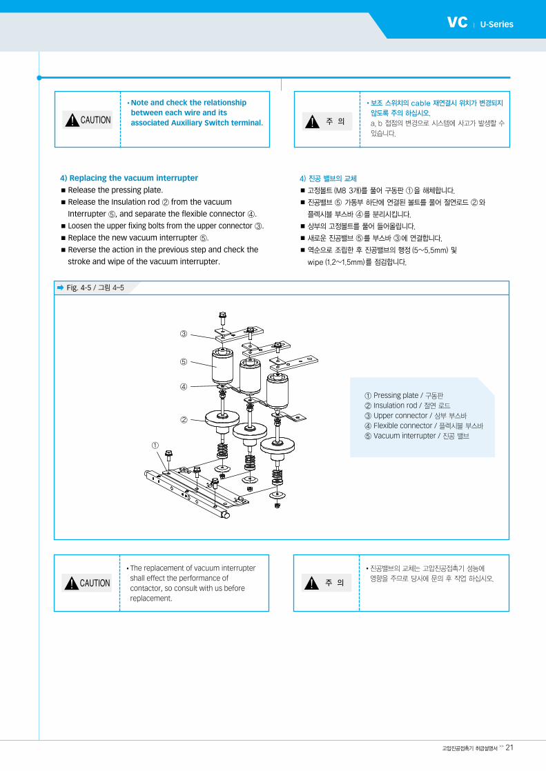
� Fig. 4-5 / 그림 4-5
4) 진공 밸브의 교체
■고정볼트(M8 3개)를 풀어 구동판 ①을 해체합니다.
■진공밸브 ⑤ 가동부 하단에 연결된 볼트를 풀어 절연로드 ②와
플렉시블 부스바 ④를 분리시킵니다.
■상부의 고정볼트를 풀어 들어올립니다.
■새로운 진공밸브 ⑤를 부스바 ③에 연결합니다.
■역순으로 조립한 후 진공밸브의 행정(5~5.5mm) 및
wipe (1.2~1.5mm)를 점검합니다.
4) Replacing the vacuum interrupter■ Release the pressing plate.■ Release the Insulation rod ② from the vacuum
Interrupter ⑤, and separate the flexible connector ④.■ Loosen the upper fixing bolts from the upper connector ③.■ Replace the new vacuum interrupter ⑤.■ Reverse the action in the previous step and check the
stroke and wipe of the vacuum interrupter.
①
②
④
⑤
① Pressing plate / 구동판
② Insulation rod / 절연 로드
③ Upper connector / 상부 부스바
④ Flexible connector / 플렉시블 부스바
⑤ Vacuum interrupter / 진공 밸브
�The replacement of vacuum interruptershall effect the performance ofcontactor, so consult with us beforereplacement.
�진공밸브의 교체는 고압진공접촉기 성능에
향을 주므로 당사에 문의 후 작업 하십시오.
③

22 << U-Series Vacuum Contactor Instruction Manual
Inspection and Maintenance 검사와 유지보수04
� Fig. 4-6 / 그림 4-6
� Fig. 4-7 / 그림 4-7
� Fig. 4-8 / 그림 4-8
5) Replacing the source control unit■ Open the rear cover (if the contactor has a rear cover). ■ Remove the cable tie.■ Pull out the control plug. (Fig. 4-6)■ Release the fixing bolt. (Fig. 4-7)■ Renew the source control unit. (Fig. 4-8)■ Reassemble reversely.
5) 콘트롤러의 교체
■후면판을 풀어냅니다. (있는 경우)
■케이블 타이를 제거합니다.
■콘트롤 플러그를 분리합니다. (그림 4-6)
■콘트롤러 고정 볼트를 풀어냅니다. (그림 4-7)
■새로운 콘트롤러로 교체합니다. (그림 4-8)
■역순으로 조립합니다.

4.5 Troubleshooting 4.5 문제점 해결표
고압진공접촉기 취급설명서>> 23
VC | U-Series
Does not close / 투입되지 않는다.
Does not open / 트립되지 않는다.
Latching motion / latch가 되지 않는다.
Burnt coil of closing electromagnet / 투입솔레노이드가 열화에 의해 소손됨
Surface flashover / 표면 방전
Probable causes / 원인
Control voltage is too low / 공급전압이 너무 낮음
Control voltage is too high / 공급전압이 너무 높음
Defective control circuit / 제어회로의 오결선
Imperfect latch mechanism / Latch mechanism 오동작
○
○
○
○
○Increase the voltage to more than 90% of the rating.공급전압을 정격의 90% 혹은 그 이상으로 높임
Decrease the voltage to lower than 110% of the rating.공급전압을 110% 이하로 낮춤
Check the control circuit diagrams.회로도를 점검함
Check the height of the roller. If necessary, adjust the height of the roller by releasing the bolt.Roller의 높이를 확인하고, 나사를 풀어 roller의 높이를 조절함
Loose bolts / 나사가 풀림
Defective operation of the control switch리미트 스위치의 오동작
Blown fuse / 퓨즈가 용단됨
Defective resistor / Resistor 불량
Interrupter without vacuum / 진공밸브의 진공 파손
Punctured rectifier / 정류기가 파손됨
○
○
○
○
○
○
Check the tightness of bolts.나사가 제 로 조여졌는지 점검함
Check the wiring and clean the contact if contact resistance is high. Replace it if necessary.접촉저항이 높으면, 전선을 확인하고 접점을 깨끗이 함
Remove the cause of the fault and replace the fuses.용단된 원인을 분석 후 교체함
Check the continuity of the resistor.Resistor 점검 후, 교체함
Check the vacuum interrupter. If necessary, replace it.진공밸브 확인 후, 필요시 교체함
Check the rectifier. If necessary, replace it.정류기 확인 후, 필요시 교체함
Check or fix / 점검 및 수리
본 사 울산광역시 동구 방어진순환도로 1000
설계: TEL. (052)202-8452~7 FAX. (052)202-8450
A/S: TEL. (052)202-8474 FAX. (052)202-8450
울산 업: TEL. (052)202-8101~8 FAX. (052)202-8100
서울사무소 서울특별시 종로구 율곡로 75
(산전기기 업) TEL. (02)746-7446, 7498, 8410 FAX. (02)746-7647
인천서비스센터 인천광역시 중구 서해 로 129
TEL. (032)888-4483 FAX. (032)881-0086
부 산 지 사 부산광역시 동구 중앙 로 361번길 14(우리아비바생명빌딩 12층)
TEL. (051)463-4382 FAX. (051)463-8843
광 주 지 사 광주광역시 서구 무진 로 966(현 빌딩별관 3층)
TEL. (062)368-9097 FAX. (062)366-9097
창 원 지 사 경상남도 창원시 성산구 봉양로 397(현 자동차빌딩 3층)
TEL. (055)286-4351 FAX. (055)286-4350
전 지 점 전광역시 동구 계족로 459(KT용전사옥 4층)
TEL. (042)622-4100 FAX. (042)625-4175
구물류센터 구광역시 북구 유통단지로 8길 120-14
TEL. (053)746-0555~6 FAX. (053)746-0557
Head Office 1000, Bangeojinsunhwan-doro, Dong-gu, Ulsan, Korea Tel: 82-52-202-6601, 6609, 6611~13 Fax: 82-52-202-6995
Seoul 75, Yulgok-ro, Jongno-gu, Seoul, Korea(Sales & Marketing) Tel: 82-2-746-7621, 8568 Fax: 82-2-746-7679
Atlanta 6100 Atlantic Blvd. Suite 201, Norcross, GA30097, U.S.A.Tel: 1-678-823-7839 Fax: 1-678-823-7553
New Jersey 300 Sylvan Avenue, Englewood Cliffs, NJ, 07632, U.S.A.Tel: 1-201-816-0286, 8028 Fax: 1-201-816-4083
London 2nd Floor, The Triangle, 5-17 Hammersmith Grove, London, W6 0LG, UKTel: 44-20-8741-0501 Fax: 44-20-8741-5620
Tokyo 8th Fl., Yurakucho Denki Bldg. 1-7-1, Yuraku-Cho, Chiyoda-Ku, Tokyo, 100-0006, JapanTel: 81-3-3212-2076, 3215-7159 Fax: 81-3-3211-2093
Osaka I-Room 5th Fl. Nagahori-Plaza Bldg. 2-4-8, Minami Senba, Chuo-Ku, Osaka, 542-0081, JapanTel: 81-6-6261-5766, 5767 Fax: 81-6-6261-5818
Mumbai 5th Floor, East Quadrant, The IL & FS Financial Centre, Plot No.C-22, G-Block, Bandra-Kurla Complex, Bandra(E), Mumbai 400 051, IndiaTel: 91-22-2653-3424 Fax: 91-22-2653-3429
Riyadh 2nd Floor, The Plaza, P.O.Box 21840 Riyadh 11485, Saudi ArabiaTel: 966-1-462-2331 Fax: 966-1-464-4696
Dubai 205, Building 4, Emaar Square, Sheikh Zayed Road, Pobox 252458, Dubai, UAETel: 971-4-425-7995 Fax: 971-4-425-7996
Kuwait 15th Floor Al Sour Tower, Al Sour Street, Al-Qiblah, KuwaitTel: 965-2291-5354 Fax: 965-2291-5355
Moscow World Trade Center, Ent.3, #1902, Krasnopresnenskaya Nab.12, Moscow, 123610, RussiaTel: 7-495-258-1381 Fax: 7-495-258-1382
Madrid Paseo De La Castellana 216, Planta 0, 28046 Madrid, SpainTel: 34-91-732-0454, 733-6069 Fax: 34-91-733-2389
Sofia 1271, Sofia 41, Rojen Blvd., BulgariaTel: 359-2-803-3200, 3220 Fax: 359-2-803-3203
Montgomery 201 Folmar Parkway, Montgomery, AL36105, U.S.A.Tel: 1-334-481-2000 Fax: 1-334-240-6869
Yangzhong No.9 Xiandai Road, Xinba Scientific and Technologic Zone, Yangzhong, Jiangsu, P.R.C.Zip: 212212, ChinaTel: 86-511-8842-0666, 0212 Fax: 86-511-8842-0668, 0231
HH
IS-WZ-LK
E-O72-00,
2012. 03 Designed by A
DP
AR
K
www.hyundai-elec.com
Related Documents