Revised 04/2020 CIVE.4310 FOUNDATION & SOIL ENGINEERING Retaining Wall Design Slide 1 of 10 TYPES OF RETAINING WALLS Figure 13.1. Das FGE (2005)

Welcome message from author
This document is posted to help you gain knowledge. Please leave a comment to let me know what you think about it! Share it to your friends and learn new things together.
Transcript

Revised 04/2020
CIVE.4310 FOUNDATION & SOIL ENGINEERINGRetaining Wall Design
Slide 1 of 10
TYPES OF RETAINING WALLS
Figure 13.1. Das FGE (2005)

Revised 04/2020
CIVE.4310 FOUNDATION & SOIL ENGINEERINGRetaining Wall Design
Slide 2 of 10Figure 13.2. Das FGE (2005)
PROPORTIONING RETAINING WALLS
NOTE:Dmin = 2 ft
Gravity Wall Cantilever Wall

Revised 04/2020
CIVE.4310 FOUNDATION & SOIL ENGINEERINGRetaining Wall Design
Slide 3 of 10
RETAINING WALL DESIGN ANALYSES
Overturning Sliding
Bearing Capacity
Figure 13.4. Das FGE (2005)

Revised 04/2020
CIVE.4310 FOUNDATION & SOIL ENGINEERINGRetaining Wall Design
Slide 4 of 10
LATERAL EARTH PRESSURES
Figure 13.3. Das FGE (2005)
Cantilever Wall

Revised 04/2020
CIVE.4310 FOUNDATION & SOIL ENGINEERINGRetaining Wall Design
Slide 5 of 10
LATERAL EARTH PRESSURES
Figure 13.3. Das FGE (2005)
Gravity Wall - Rankine Gravity Wall - Coulomb

Revised 04/2020
CIVE.4310 FOUNDATION & SOIL ENGINEERINGRetaining Wall Design
Slide 6 of 10
goverturnin
resistinggoverturnin M
MFS
CHECK FOR OVERTURNING
FS ≥ 1.5 to 2
Forces Acting Against Retaining Wall
Cantilever Gravity
Figure 13.5. Das FGE (2005)
NOTE:Neglect Pp for Mresisting

Revised 04/2020
CIVE.4310 FOUNDATION & SOIL ENGINEERINGRetaining Wall Design
Slide 7 of 10
driving
resistingsliding F
FFS
CHECK FOR SLIDING
Forces Acting Against Retaining Wall
Figure 13.6. Das FGE (2005)
FS ≥ 1.5 to 2
acBVR tan
Where:
R' = Friction Force along Base' = Interfacial Friction Anglec'a = Adhesion
Optional Key

Revised 04/2020
CIVE.4310 FOUNDATION & SOIL ENGINEERINGRetaining Wall Design
Slide 8 of 10
cosaPVR
goverturninresistingnet MMM
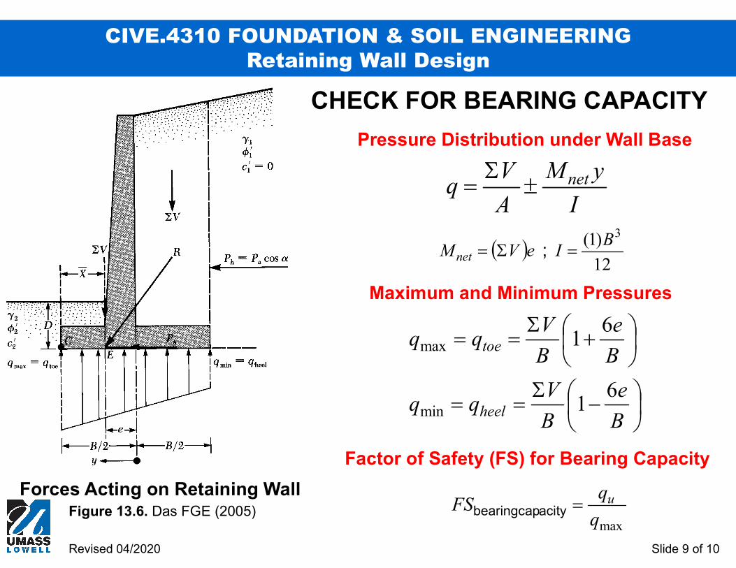
CHECK FOR BEARING CAPACITY
Forces Acting on Retaining WallFigure 13.6. Das FGE (2005) CE
Be
2
V
MXCE net
Resultant Force on Bottom of Wall (R)
Net Moments about Point C (i.e. Wall Toe)
Distance from Toe to Location of R (CE)
Eccentricity of Resultant (e)
Revised 04/2020
CIVE.4310 FOUNDATION & SOIL ENGINEERINGRetaining Wall Design
Slide 9 of 10
12
)1( 3BIeVM net ;
I
yM
A
Vq net
CHECK FOR BEARING CAPACITY
Forces Acting on Retaining WallFigure 13.6. Das FGE (2005)
maxq
qFS uacitybearingcap
B
e
B
Vqq
B
e
B
Vqq
heel
toe
61
61
min
max
Factor of Safety (FS) for Bearing Capacity
Pressure Distribution under Wall Base
Maximum and Minimum Pressures

Revised 04/2020
CIVE.4310 FOUNDATION & SOIL ENGINEERINGRetaining Wall Design
Slide 10 of 10
EFFECT OF SURCHARGE ON ACTIVE THRUST
P' = qHKa
Uniform Load q
P'H
W+qb
b
H/2
Related Documents