July 2018 Type OS/66 Type OS/66 Slam-Shut Controller SUMMARY Introduction ........................................................................ 1 Characteristics ................................................................... 1 Labelling ............................................................................ 2 Dimensions and Weights ................................................... 2 Installation ......................................................................... 2 Startup ............................................................................... 2 Periodical Checks .............................................................. 2 SEP Statement .................................................................. 2 ATEX Requirements .......................................................... 2 Maintenance ...................................................................... 3 Spare Parts ........................................................................ 4 Troubleshooting ................................................................. 4 Parts List ............................................................................ 5 Schematic Assemblies ....................................................... 6 INTRODUCTION Scope of the Manual This manual provides installation, startup, maintenance, troubleshooting, and spare parts for the slam-shut controller series OS/66. Product Description Designed for pressure regulators and slam-shut valves control, the following types are available: • Types OS/66 and OS/66-AP Spring loaded. Tightness cover version available on request. The full range of Type OS/66 slam-shut controller can be installed in the following equipment: M Series - A/100 Series - A/140 Series - B/240 Series RP Series - BM7 Series This product has been designed to be used with fuel gases of 1st and 2nd family according to EN 437, and with other non aggressive and non fuel gases. For any other gases, other than natural gas, please contact your local sales agent. CHARACTERISTICS Table 1. Type OS/66 Characteristics 1/8” BSP female threaded connections. Materials Body: Aluminum Cover: Aluminum Diaphragm: Nitrile (NBR) rubber TYPE BODY RESISTANCE bar OVERPRESSURE SET RANGE W do bar UNDERPRESSURE SET RANGE W du bar Min. Max. Min. Max. OS/66 6 0.022 0.6 0.007 0.45 OS/66-AP 0.2 5 0.1 2.5 Instruction Manual D103657X012 Figure 1. Type OS/66 Slam-Shut Controller

Welcome message from author
This document is posted to help you gain knowledge. Please leave a comment to let me know what you think about it! Share it to your friends and learn new things together.
Transcript

July 2018
Type OS/66
Type OS/66 Slam-Shut ControllerSUMMARYIntroduction ........................................................................ 1
Characteristics ................................................................... 1
Labelling ............................................................................ 2
Dimensions and Weights ................................................... 2
Installation ......................................................................... 2
Startup ............................................................................... 2
Periodical Checks .............................................................. 2
SEP Statement .................................................................. 2
ATEX Requirements .......................................................... 2
Maintenance ...................................................................... 3
Spare Parts ........................................................................ 4
Troubleshooting ................................................................. 4
Parts List ............................................................................ 5
Schematic Assemblies ....................................................... 6
INTRODUCTION
Scope of the ManualThis manual provides installation, startup, maintenance, troubleshooting, and spare parts for the slam-shut controller series OS/66.
Product DescriptionDesigned for pressure regulators and slam-shut valves control, the following types are available:
• Types OS/66 and OS/66-APSpring loaded.
Tightness cover version available on request.
The full range of Type OS/66 slam-shut controller can be installed in the following equipment:
M Series - A/100 Series - A/140 Series - B/240 Series RP Series - BM7 Series
This product has been designed to be used with fuel gases of 1st and 2nd family according to EN 437, and with other non aggressive and non fuel gases. For any other gases, other than natural gas, please contact your local sales agent.
CHARACTERISTICSTable 1. Type OS/66 Characteristics
1/8” BSP female threaded connections.
MaterialsBody: AluminumCover: AluminumDiaphragm: Nitrile (NBR) rubber
TYPEBODY
RESISTANCE bar
OVERPRESSURE SET RANGE
Wdo bar
UNDERPRESSURE SET RANGE
Wdu bar
Min. Max. Min. Max.
OS/666
0.022 0.6 0.007 0.45
OS/66-AP 0.2 5 0.1 2.5
Instruction ManualD103657X012
Figure 1. Type OS/66 Slam-Shut Controller
Type OS/66
2
APPARECCHIO TIPO / DEVICE TYPE
Wau
DN2
DN1MATRICOLA
bar
bar
SERIAL Nr.
°C
FLUIDO GRUPPOFLUID GROUP
ANNOYEAR
HARMONIZED STD.
bar
NORME ARMONIZ.
LEAKAGE CLASSCLASSE DI PERDITA
FUNCTIONAL CLASSCLASSE FUNZIONALE
bar
Wao
Wa
TS bar
pao
Cg
PSbody bar PT= x PS barPS
covers
EN
barpmax
BOLOGNA ITALYO.M.T.
1.5
Note 4Note 5Note 5
Note 3
Note 2
Note 1
1-
112
∅ 125
170
S A C
INSTALLATION
a. Install the actuator in a covered area and, in any case, protect it against weather agents.
b. Make sure that data shown on actuator label is compatible with actual operating requirements.
c. In case of impulse line not being incorporated in the pressure regulator, connect the (A) from the pipe downstream of the actuator to a straight pipe section possibly away from restrictions, curves or branches in order to avoid any variations in device triggering values which might be caused by gas turbulence (see Figure 7).
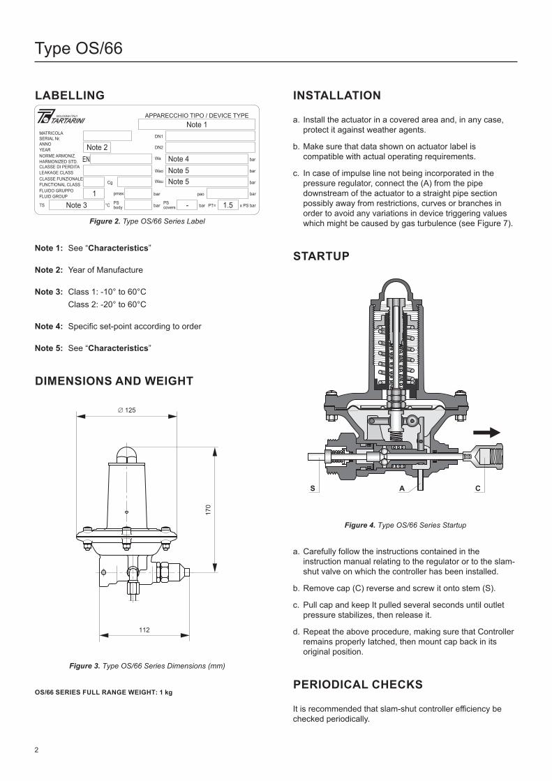
STARTUP
Figure 4. Type OS/66 Series Startup
a. Carefully follow the instructions contained in the instruction manual relating to the regulator or to the slam-shut valve on which the controller has been installed.
b. Remove cap (C) reverse and screw it onto stem (S).
c. Pull cap and keep It pulled several seconds until outlet pressure stabilizes, then release it.
d. Repeat the above procedure, making sure that Controller remains properly Iatched, then mount cap back in its original position.
PERIODICAL CHECKS
It is recommended that slam-shut controller efficiency be checked periodically.
LABELLING
Figure 2. Type OS/66 Series Label
Note 1: See “Characteristics”
Note 2: Year of Manufacture
Note 3: Class 1: -10° to 60°C Class 2: -20° to 60°C
Note 4: Specific set-point according to order
Note 5: See “Characteristics”
DIMENSIONS AND WEIGHT
Figure 3. Type OS/66 Series Dimensions (mm)
OS/66 SERIES FULL RANGE WEIGHT: 1 kg

Type OS/66
3
!!
TIPOTYPE
MATRICOLASERIAL NR.
BOLOGNA ITALY
ANNOYEAR
DESTINAZIONE D’USOINTENDED USE
II 2 G T
II 2 G T
Cut-off Testa. Close inlet and outlet valves and disconnect impulse line
(A). The controller should trigger at minimum pressure (only if so set).
b. Using a small pump or other appropriate means, raise pressure in the line to normal operating level. Relatch controller in case it has triggered following on step a above.
c. Simulate pressure increase until maximum triggering pressure is reached.
d. Connect the impulse line (A) and bring the line back to full operating conditions as described in Startup paragraph.
Controller-seal Check
a. Slowly close the valve located downstream.
b. Loosen cap (key 1) and trip the controller by exerting a slight pressure on stem unit (key 41).
c. Loosen one fitting in the line downstream of the slam-shut valve and apply soapy water in order to make sure that there are no leaks. In case of any leak being detected, proceed with the necessary maintenance of the controller.
SEP STATEMENTEmerson declares this product conforms to Pressure Equipment Directive PED 2014/68/UE Article 4 section 3 and have been designed and manufactured in accordance with sound engineering practice (SEP).
Per Article 4 section 3, this “SEP” product must not bear the CE marking.
ATEX REQUIREMENTS
Application of ATEX Product Directive:
Table 2. Overview
Carefully follow below instructions for the usage of “ATEX Assembly” in an explosive atmosphere.
A non-electrical equipment incorporating an electrical device (proximity, microswitch...) is an “ATEX Assembly”, and in the scope of the ATEX Directive 2014/34/EU.
When such equipment(s) is used in a natural gas pressure control and/or measuring station in compliance with the following European standards: EN12186, EN12279 and EN 1776, can be installed in any type of classified zones according to the Directive 1999/92/EC dated 16 December 1999, in the following conditions:
a) the equipment(s) / electrical circuit is connected to a suitable and certified intrinsically safe apparatus (suitable zener barrier)
b) the equipment(s) / electrical circuit is used according to this instruction manual issued by the manufacturer and / or available on our website
ATEX LabellingThe nameplate will be installed on the ATEX assembly.
Figure 5. Label for ATEX Assembly
Where:
• Manufacturer: Name and address and/or logo of the manufacturer
• : Conformity marking to European Directive
• Type: Description of the ATEX Assembly
• Serial Number and Year of Construction
• : Specific marking of explosion protection
• II: Equipment group
• 2: Equipment Category/level of protection 2 = suitable for zone 1
• G: For gases, vapor or mists
• T: Temperature Class (i.e.: T6 > 85 … ≤ 100 °C)
• Intended Use: Natural Gas infrastructures
MAINTENANCE
Call a gas service person to service the unit. Only a qualified person must install or service the device.
TYPE CLASSIFICATION ATEX ASSEMBLIES
ATEX LABELLING
Regulator/SSD Non-electrical equipment
Not falling under the 2014/34/EU
DirectiveNo
Regulator/SSD +
electrical device
Non-electric equipment equipped
with an electrical device falling under
the scope of the ATEX Directive
2014/34/EU
Constitutes an assembly according to
the 2014/34/EU Directive
WARNING WARNING

Type OS/66
4
!
Before starting maintenance, disconnect impulse connection (A) to make sure there is no gas under pressure in the pilot.
When maintenance operations are finished check the tightness with suds.
General Maintenance
Do not bend or otherwise damage stem (S) when disassembling and reassembling.
a. Remove impulse line (A) and make sure that controller is not latched by exerting a slight pressure on stem unit (key 41).
b. Loosen screws (key 29) and slide out the controller.
c. Remove cap (key 1), adjusting screw (key 2), ring nut (key 4), spring (key 5), spring holder (key 3) and spring (key 6).
d. Remove screws (key 27) nuts (key 25) and washers (key 26), take off cover (key 7).
e. Slide out diaphragm unit and remove spring (key 23).
f. In order to replace diaphragm (key 36), unscrew nuts (key 39 and 40) and disassemble the components. Check O-ring (key 34) and replace it if worn.
g. Check that plate unit (key 8) and lever (key 24) can move freely and are not worn, otherwise replace them together with pins (key 22 and 9).
h. Loosen balls holder (key 12) using the appropriate tool and check O-ring (key 11).
i. Remove the balls (key 12), the spring holder (key 13) and the spring (key 14). Clean with petrol and check surfaces if worn or scored, replace.
j. Unscrew guide (key 20) and check O-rings (key 18 and 19), replace if necessary.
ReassemblingReassemble by reversing the above steps.
As you proceed, make sure that parts move freely and without friction.
In addition:
a. Lubricate all seals with Molykote 55 M or equivalent and be very careful not to damage them when reassembling.
b. Place the balls holder (key 10) on the special tool, grease it thoroughly to prevent balls from falling out and lodge the balls (key 12) in their seats. Hold the special tool in a vertical position and tighten the balls holder.
c. Adjust the position of balls holder (key 10) so that, with lever (key 24) held down at travel end, plate unit (key 8) moves freely and has a clearance of 0,2 to 0,3 mm.
d. Place the adjusting nut (key 40) back in its original position as shown in Figure 4.
e. Hold stem unit (key 41) slightly pressed to ensure proper fitting of diaphragm (key 36). Mount cover (key 7) and check that stem unit (key 41) is duly centered.
f. Tighten cover screws (key 27) nuts (key 25) and washers (key 26) to ensure proper sealing.
g. Check that all movements are smooth and friction free.
h. Fit the mounting stem in order to prevent balls from falling out and to facilitate remounting of the controller on the sam-shut valve.
i. Remount the controller and secure it by means of screws (key 29).
Settinga. Use ring nut (key 4) to completely load maximum
pressure spring (key 5). Loosen adjusting screw (key 2) to completely relieve minimum pressure spring (key 6).
b. Disconnect impulse line (A).
c. Use a small pump or other appropriate means to raise pressure to normal operating level.
d. Relatch controller and allow pressure to drop to minimum pressure triggering level.
e. Using adjusting screw (key 2), slowly load minimum pressure spring (key 6) until actuator triggers.
f. Repeat steps c. and d. above, making any necessary adjustments in setting.
g. Bring pressure back to normal values.
h. Relatch controller and raise pressure until it reaches maximum pressure triggering level.
i. Using ring nut (key 4), slowly unload spring (key 5) until actuator triggers.
j Repeat steps g. and h. above, making any necessary adjustments in setting.
Whenever minimum or maximum pressure triggering is not required, omit corresponding steps.
It should be borne in mind that minimum pressure triggering can be eliminated by simply removing spring (key 6) and that maximum pressure triggering can be eliminated by fully loading spring (key 5).
SPARE PARTS
Spare parts storage shall be done by proper procedures according to national standard/rules to avoid over aging or any damage.
CAUTION
WARNING

Type OS/66
5
TROUBLESHOOTING
Table 3. Troubleshooting for Type OS/66 Series Slam-Shut Controller
SYMPTOMS CAUSE ACTIONS
Controller does not remain Iatched
The impulse intake (A) is notconnected properly Check connection (A)
Downstream pressure coincides with themaximum or minimum slam-shut settings Check settings
Minimum or maximum pressure setting is above or below required values Check settings
Diaphragm (key 36) is damaged (minimum pressure triggering) Replace diaphragm
Gap between plate unit (key 8) and lever (key 24) is not as required Check gap
PARTS LISTType OS/66 Slam-Shut Controller(See Figure 6)Key Description
1 Cap 2 Adjusting screw 3 Spring holder 4 Ring nut 5 Maximum pressure spring 6 Minimum pressure spring 7 Cover 8 Plate unit 9 Pin 10 Balls holder 11* O-ring 12 Ball 13 Spring holder 14 Spring 15 Body 17 Pipe 18* O-ring 19* O-ring 20 Guide 21 Cover 22 Pin 23 Spring 24 Lever 25 Nut
Key Description
26 Washer 27 Screw 28 Label 29 Screw 30 Screw 32 Screw 33 Screw 34* O-ring 35 Washer 36* Diaphragm 37 Plate 38 Washer 39 Nut 40 Adjusting nut 41 Stem unit 200 Proximity switch 201 Disc 202 Nut 203 Bracket
Rubber parts marked with (*) are supplied in the “spare parts kit”, recommended as stock.
To order the kit it is necessary to communicate to us the type of the controller and its serial number.

Type OS/66
6
LM/1345
1
2
3
4
5
6
7
810
9
8
1011121314151718192021
22
23
24
25
24
26
27
GRUPPOMEMBRANA
COLLEGARE A VALLEDEL REGOLATOREVEDI FIGURA 7
FALSO STELO
A
28
29
30
32
33
GRUPPO MEMBRANA OS/66
Quota dado di registro
Registrare il gioco fra il gruppo piastrina(pos. 8) e la leva (pos. 24) agendo conl’apposita chiave speciale sul portasfere(pos. 10)
34
35
36 37 38
39
40
41
23,2
mm
0,2 a 0,3 mm
GRUPPO MEMBRANA OS/66-AP
41
35
34
40 39373642
25 m
m
Quota dado di registro
SCHEMATIC ASSEMBLIES
Figure 6. Type OS/66 Series Slam-Shut Controller

Type OS/66
7
LM/1345
1
43
7
VERSIONE CON PROXIMITY
200
201
202
203
VERSIONE CON COPERCHIO A TENUTA
Figure 6. Type OS/66 Series Slam-Shut Controller (continued)

Type OS/66
Tartarini-NaturalGas.com
Emerson Automation Solutions
4 DN
DN
Organo di Sgancio OS/66
Presa d’impulso di valletubo Ø 6
Regolatore
Figure 7. Type OS/66 Series Impulse Line Connection Schematic
D103657X012 © 2018 Emerson Process Management Regulator Technologies, Inc. All rights reserved. 7/18. The Emerson logo is a trademark and service mark of Emerson Electric Co. All other marks are the property of their prospective owners. Tartarini™ is a mark owned by O.M.T. Officina Meccanica Tartarini s.r.l., a business of Emerson Automation Solutions.
The contents of this publication are presented for informational purposes only, and while every effort has been made to ensure their accuracy, they are not to be construed as warranties or guarantees, express or implied, regarding the products or services described herein or their use or applicability. All sales are governed by our terms and conditions, which are available upon request. We reserve the right to modify or improve the designs or specifications of such products at any time without notice.
Emerson Process Management Regulator Technologies, Inc does not assume responsibility for the selection, use or maintenance of any product. Responsibility for proper selection, use and maintenance of any Emerson Process Management Regulator Technologies, Inc. product remains solely with the purchaser.
O.M.T. Officina Meccanica Tartarini S.R.L., Via P. Fabbri 1, I-40013 Castel Maggiore (Bologna), Italy R.E.A 184221 BO Cod. Fisc. 00623720372 Part. IVA 00519501209 N° IVA CEE IT 00519501209, Cap. Soc. 1.548 000 Euro i.v. R.I. 00623720372 - M BO 020330
Francel SAS, 3 Avenue Victor Hugo, CS 80125, Chartres 28008, France SIRET 552 068 637 00057 APE 2651B, N° TVA : FR84552068637, RCS Chartres B 552 068 637, SAS capital 534 400 Euro
Americas McKinney, Texas 75070 USA T +1 800 558 5853
+1 972 548 3574
Europe Bologna 40013, Italy T +39 051 419 0611
Asia Pacific Singapore 128461, Singapore T +65 6770 8337
Middle East and Africa Dubai, United Arab Emirates T +971 4 811 8100
[email protected] Facebook.com/EmersonAutomationSolutions
LinkedIn.com/company/emerson-automation-solutions
Twitter.com/emr_automation
Americas McKinney, Texas 75070 USA T +1 800 558 5853
+1 972 548 3574
Europe Bologna 40013, Italy T +39 051 419 0611
Asia Pacific Singapore 128461, Singapore T +65 6770 8337
Middle East and Africa Dubai, United Arab Emirates T +971 4 811 8100
Related Documents