INSTALLATION MANUAL TYPE MA General Purpose Converter without controls TYPE MA-R Converter with integral fused disconnect switch TYPE MA-A,-AW,-AI Converter with remote start magnetic controls CONTENTS I. CONVERTER CONFIGURATIONS AND ACCESSORIES ........................................... 2 II. BEFORE YOU START .................................................................................................. 3 III. SIZING THE SINGLE-PHASE SERVICE ...................................................................... 4 IV. INSTALLATION ............................................................................................................ 4 GENERAL WIRING INSTRUCTIONS ..................................................................... 4 TYPE MA CONVERTER – WITHOUT CONTROLS ................................................ 4 TYPE MA-R CONVERTER WITH BUILT-IN SWITCH............................................. 5 TYPE MA-A, AW, AI AUTOMATIC CONVERTER ............................................... 6,7 0302-MA CONNECTION DIAGRAM ....................................................................... 8 0302-MA-R CONNECTION DIAGRAM ................................................................... 9 0302-A, AI CONNECTION DIAGRAM .................................................................. 10 0302-AW CONNECTION DIAGRAM ..................................................................... 11 V. OPERATING INSTRUCTIONS FOR LOAD RANGE CONTROLLER (-VS)................ 12 VI. CONVERTER CHECKOUT ......................................................................................... 13 VII. OPERATION & MAINTENANCE ................................................................................ 14 LUBRICATION ...................................................................................................... 14 INSPECTION ........................................................................................................ 14 MAINTENANCE SCHEDULE................................................................................ 14 VIII. IN CASE OF TROUBLE.............................................................................................. 15 NOTES & WARRANTY............................................................................................... 16 MODEL NUMBER SERIAL NUMBER Kay Industries, Inc. 2014

Welcome message from author
This document is posted to help you gain knowledge. Please leave a comment to let me know what you think about it! Share it to your friends and learn new things together.
Transcript

INSTALLATION MANUAL TYPE MA General Purpose Converter without controls TYPE MA-R Converter with integral fused disconnect switch TYPE MA-A,-AW,-AI Converter with remote start magnetic controls
CONTENTS
I. CONVERTER CONFIGURATIONS AND ACCESSORIES ........................................... 2
II. BEFORE YOU START .................................................................................................. 3
III. SIZING THE SINGLE-PHASE SERVICE ...................................................................... 4
IV. INSTALLATION ............................................................................................................ 4
GENERAL WIRING INSTRUCTIONS ..................................................................... 4
TYPE MA CONVERTER – WITHOUT CONTROLS ................................................ 4
TYPE MA-R CONVERTER WITH BUILT-IN SWITCH ............................................. 5
TYPE MA-A, AW, AI AUTOMATIC CONVERTER ............................................... 6,7
0302-MA CONNECTION DIAGRAM ....................................................................... 8
0302-MA-R CONNECTION DIAGRAM ................................................................... 9
0302-A, AI CONNECTION DIAGRAM .................................................................. 10
0302-AW CONNECTION DIAGRAM ..................................................................... 11
V. OPERATING INSTRUCTIONS FOR LOAD RANGE CONTROLLER (-VS) ................ 12
VI. CONVERTER CHECKOUT ......................................................................................... 13
VII. OPERATION & MAINTENANCE ................................................................................ 14
LUBRICATION ...................................................................................................... 14
INSPECTION ........................................................................................................ 14
MAINTENANCE SCHEDULE ................................................................................ 14
VIII. IN CASE OF TROUBLE .............................................................................................. 15
NOTES & WARRANTY............................................................................................... 16
MODEL NUMBER SERIAL NUMBER
Kay Industries, Inc. 2014

2
I. CONVERTER CONFIGURATIONS: These installation instructions apply to the following Phasemaster® converter configurations.
Type Description Cat No. Format
Connection Drawing
MA
The basic general-purpose converter configuration. It is provided with a lead box with bolted lug or terminal blocks for line and load side connections. This converter requires some type of field supplied and mounted primary disconnect switch for on-off control.
MA-2
0302-MA
Page 8
MA-R
Type MA converter with the primary fused disconnect switch built into the converter. This construction includes a large side-mounted wiring compartment that houses the switch, fuses, and input output terminal blocks.
MA-2-R 0302-MAR
Page 9
MA-A
Type MA converter with magnetic contactor, power fuses, and timing relay for coordination with unattended cyclical loads. This configuration passes through single-phase power for controls.
MA-2-A 0302-A Page 10
MA-AW
This configuration contains the same starting controls as the type MA-A except it does not include a timing relay. The added “W” suffix means the converter is manually started from a hard-wired remote pilot control such as a start-stop pushbutton station.
MA-2-AW 0302-AW
Page 11
MA-AI
Same as the MA-A except the converter contains an adjustable interval timer that keeps the converter operating for some preset period of time after the most recent equipment operation. It is typically used on elevators, car washes and other applications that are subject to multiple consecutive operations. The timer reduces the need for multiple restarts thus saving wear on controls and stress on the utility supply.
MA-2-AI 0302-A
Page 10
ACCESSORIES: The converter types listed above can be equipped with various accessories that are listed on the nameplate as part of the catalog number. The following suffix letters indicate which accessories are included.
-VS
This is the Load Range Controller feature which automatically adjusts the converter’s output voltage up or down to accommodate changes in load. It is particularly helpful in operating very small loads. It also enables the converter to easily handle variable speed drives and CNC equipment without causing overvoltage conditions that could prevent the drive from starting. See the –VS accessory instructions on page 11.
-TC
This is the Thermostatic Control accessory for use on HVAC equipment. It includes a set of control relays and terminal blocks that enable the thermostat control wiring to be rerouted through the converter to start it on demand. Connection diagram is supplied in a supplement to this booklet. A 24 volt input is required for converter operation.
-CL
The converter is equipped with current limiting starting accessory that starts the converter in stages and reduces the starting current demand on the utility supply. This accessory adds an additional contactor to the starting circuit. Factory set timing relays adjust the switching time and sequencing of these contactors. Normally no further adjustments are required in the field. Instructions for this accessory are supplied in a supplement to this booklet.
-L
Indicates the converter is equipped with lightning and surge protection. This feature is normally included on installations that are located in remote areas where lightning strikes and/or line surges are a common event. It functions without adjustment and provides a degree of protection for the converter alone when surges get past all other protective devices upstream from the converter. No special action is required to activate the surge protection. The glowing indicating lamp on the protector indicates it is in working order and operating. No further operating instructions are required.
-BB Indicates the converter includes a built-in buck boost transformer on the single-phase input side. The transformer is pre-connected for a specific voltage change and does not require any additional wiring.
-OC Converter is equipped with an output contact to prevent transformers or other downstream devices from being energized until the converter is fully up to speed and producing 3-phase.

3
BEFORE YOU START
CHECK YOUR ACTUAL INCOMING LINE VOLTAGE AND NAMEPLATE VOLTAGE OF YOUR LOAD EQUIPMENT
Motors and electrical equipment built in North America are rated to operate at 230V ±10%. However, most 3-phase machines manufactured in Europe and Asia are actually designed for operation on 220V systems. Although they are capable of running at voltages up to 10% above 220V (242V), North American utility voltages can legally be as high as 252V. Utility companies generally will not accept responsibility for equipment damage unless the voltage exceeds this level. If your voltage measures above 240V at any time, it is highly probable that it could go even higher on other occasions depending on the time of day or seasonal power load. This means your equipment is likely to see voltages in excess of 242V coming from the converter. If your machines are designed for European or Asian voltages, you should consider installing a buck-boost transformer AHEAD of the converter to reduce the utility supply voltage. This is particularly important if your machine incorporates a variable speed drive. The buck-boost transformer will generally eliminate or minimize problems that result from excessive utility supply voltage. Contact Kay Industries for further explanation of this subject and for exact recommendations of the proper size buck-boost transformer for your application.
Kay Industries has designed the Phasemaster Rotary Phase Converter to be installed by anyone having basic electrical knowledge and mechanical skills. If you do not thoroughly understand these instructions, we recommend you obtain the assistance of a licensed electrician. These instructions are based upon Article 455 of the most recent National Electrical Code (NEC). Although we present a practical set of guidelines for converter installation, we do not intend to supersede or modify the requirements of the NEC or any applicable local codes. We suggest that you consult these references to determine whether your particular installation complies with applicable regulations. If feasible, it is always a good idea to temporarily connect the phase converter and the load to verify performance before proceeding with the permanent installation. Whether this is your first phase converter installation or your one-hundredth, there are a few do’s and don’ts that you should observe.
DO: DON’T:
DO: Install a starter and fuses, or a fused disconnect switch (if your converter does not have internal fuses) after the single-phase circuit breaker but ahead of the converter. This is the best way to provide on-off control.
DON’T: Cut corners by using the circuit breaker for on-off control instead of a fused switch or starter. A breaker is not designed for as many operations as a switch and may wear out prematurely if subjected to many repeated converter starting cycles.
DO: Remove the converter from the skid
DON’T: Bolt the converter down.
DO: Bolt or crimp all connections. Insulate all connections with rubber and plastic tape or heat shrinkable tubing.
DON’T: Use wire nuts or twist type connectors to connect the converter.
DO: Connect all single-phase loads, including controls, only to utility lines L1 and L2.
DON’T: Connect the manufactured leg T3 to any control circuits or to any single-phase loads.

4
III. SIZING THE SINGLE-PHASE SERVICE
It is extremely important to supply the phase converter with an adequately sized 1-phase circuit for the total planned 3-phase load. There are several ways to arrive at the size of the required 1-phase service but the simplest are the, EXPRESS METHOD and by actual CALCULATION. Express Method As a rule the single fastest way to calculate the necessary circuit size is to provide a MINIMUM of five (5) and preferably six (6) amps of single-phase 240V service for every horsepower or kilowatt of simultaneously operating load. (On this basis a total load of 25 HP should be fed from a 1-phase breaker not smaller than 125A.) This method will assure that virtually any connected load up to the maximum will operate without tripping the single-phase feeder breaker. However, using six (6) amps per horsepower will assure absolute compliance with the extremely conservative requirements of the NEC. Calculation Method 1. Add the total 3-phase full load currents for every load that operates simultaneously. If the equipment
nameplate does not show full load amperage, you can estimate that every motor will draw 2.6 amps per horsepower at 230 volts. For example, a 20 HP motor will pull approximately 52A of 3-phase current at full load. If you are operating at 208 or 460 volts you must adjust the current accordingly. Use 2.8 amps/HP for 208 volts and 1.3 amps/HP for 460 volts.
2. Multiply the total 3-phase full load current from Step 1 times 1.732. This is the exact single-phase
current that you will draw from your service panel. 3. Multiply the 1-phase current determined in step 2 by the NEC safety margin of 1.25. This is now the
minimum 1-phase service you will need to operate the load. This is also the minimum ampacity requirement for the 1-phase wire size from the service panel to the converter. This is a conservative way to select your wire and branch circuit size and will assure your compliance with code.
If you use a breaker of smaller rating than called for by this calculation, it may trip when the
converter starts or may be too small to handle the entire planned load. To determine the single and 3-phase wire size required, disconnect switch and fuse ratings, refer to the table and diagram on drawing 0302-MA, 0302-A, 0302-AW or 0302-MAR.
IV. INSTALLATION
BEFORE YOU CONNECT ANY WIRES Be sure all POWER IS OFF at the main panel.
SELECTING A CONVERTER LOCATION
Pick a location as close as practical to the incoming single-phase service panel or if preferred, near the 3-phase load. It should be a dry location with adequate ventilation free of dirt, filings, chips, sawdust and other debris that could enter the converter through the ventilation intakes. The converter warranty does not cover failure caused by water or foreign material ingress. The converter should be installed on the floor or other solid surface. Kay Industries also offers weatherproof enclosures for outdoor installation.
GENERAL WIRING INSTRUCTIONS (APPLIES TO ALL CONVERTER TYPES)
Remove the converter from the skid and set it in place on the mounting pads included in the package. Do not bolt the converter to the floor or any other mounting surface. Rigid mounting amplifies noise, increases internal vibrations that can loosen terminals and can distort the frame causing the rotor to lock. If feasible, it is always a good idea to temporarily connect the phase converter and the load to verify it is adequate for the load before proceeding with the permanent installation. This can usually be done quickly and may save a great deal of time and labor if an exchange is necessary.

5
TYPE MA CONVERTER Type MA converters are pre-wired to operate on 230 volts unless ordered otherwise. Do not reconnect the leads in the junction box unless you need to operate the converter on 460 volts input. Many, but not all converters may be field changed to 460V. Consult Kay Industries to determine if your converter can be reconnected. The input voltage of Type MA-A and MA-R converters cannot be changed without additional modifications. Consult Kay Industries if this change is necessary. All phase converters produce three-wire delta output only. For four-wire wye output, consult the factory for an appropriate transformer. 1. Consult Drawing 0302-MA to determine which connection configuration is most appropriate for your
application. 2. Mount the fused disconnect switch as close as practical to the converter. Connect the disconnect
switch to the single-phase branch circuit wire at the service with wire size not less than shown on Drawing 0302-MA. If the location of the converter is more than 50 feet from the service panel or if using aluminum wire, then increase the wire size appropriately.
3. Connect the load side of your fused disconnect to the converter leads marked L1 and L2 in the junction
box. Lead T3 is the manufactured phase. If you are using a three-pole fused disconnect, connect T3 to the third pole on the load side of the switch. If you are using a two-pole disconnect, run T3 directly to the line side of the load disconnect or other load switching device.
4. Connect the single-phase power supply from the line side of your fused disconnect to the L1 and L2
terminals of the load disconnect switch. 5. Ground the converter by attaching the system ground wire to the ground lug in the converter junction
box. If you have not grounded your load, do so before proceeding.
Label all wires "L1", "L2" and "T3" uniformly throughout the entire system. This will avoid
confusion in wire tracing should any troubleshooting become necessary later.
TYPE MA-R CONVERTER WITH BUILT-IN SWITCH AND FUSES The Type MA-R converter includes built-in switch and fuses which have been appropriately sized for the load. Determine the proper single and three-phase wire size from the table in drawing 0302-MAR. The input voltage of Type MA-A and MA-R converters cannot be changed without additional modifications. Consult Kay Industries if this change is necessary. All phase converters produce three-wire delta output only. For four-wire wye output, consult the factory for an appropriate transformer. Refer to connection drawing 0302-MAR to determine the proper wire size for your converter model. 1. Route all power cables and ground conductor in properly sized rigid or flexible conduit from the phase
converter control enclosure to the load and from the service panel to the converter. 2. Connect the appropriate sized single-phase wire size from the service panel Single-Phase input
terminals L1 and L2 in the converter control box. Make the necessary penetrations in the converter enclosure and secure the conduits at both ends. If you are using flexible multi-conductor cable instead of wiring in rigid or flexible conduit, be certain to use a suitable strain relief fitting where the cables enter and leave the converter enclosure.
3. Connect the single-phase supply lines L1, L2, and Ground to the input terminal blocks on the converter
connection panel. Connect the output cables to the output terminals labeled T1, T2 and T3.

6
TYPE MA-A, -AW, -AI CONVERTER WITH AUTOMATIC CONTROLS The Phasemaster® Automatic converter (Type MA-A,-AW,-AI) is identical in electrical performance to the non-automatic converter except that it is equipped with magnetic controls that enable it to be started on demand from a remote pilot control device, pushbutton station, or wireless controller. Type MA-A and MA-AW converters are equipped with a three-position selector switch. Make sure the switch is in the OFF position during installation. Converter wiring is divided into power and control connections. Power connections include the 1-phase input and 3-phase output wiring. Control connections include the control wiring that is responsible for directing the converter to start and stop. Power Connections - Applies to All Converter Types Determine the proper size single-phase branch circuit for the load. Refer to Section II on page 4 for a detailed discussion of the calculations. Refer to the table on drawings 0302-A or 0302-AW for the recommended single and three-phase wire size. With properly sized cables and conduits in place, you are ready to make the power connections 1. Connect the input power leads to L1 and L2 on the input terminal block in the
converter enclosure. Connect the ground (NOT NEUTRAL) wire to the terminal marked “Ground”. Tighten all connections securely.
2. Connect the output power cables to the output terminals designated L1, L2, and T3 in the starter panel enclosure. Tighten the terminal blocks securely and label each line with the corresponding phase identification. Later, you may change these connections at the load to obtain the correct rotation, but keep the labels on the cables so that they are marked consistently throughout the system.
3. Be sure that line T3 is not supplying power to any relays or other control
components inside the load.
IMPORTANT SAFETY NOTE TYPE MA-A CONVERTER The L1 and L2 lines at the 3-PHASE output terminals are always ENERGIZED regardless of whether the converter is on or off. This assures the load always has continuous control power available. The L1 and L2 output terminals on the Type MA-AW converter are ENERGIZED ONLY when the converter is on.
Control connections - Type MA-A, -AI The phase converter must be operating before the load can be turned on. This converter control is designed for loads that cycle automatically such as air compressors, air conditioners, sump pumps, etc. To accomplish this, the converter is energized from some type of pilot switch actuator on the load machine. Examples of this actuator are tank pressure switch on an air compressor or a float switch on a pump. These actuators simply close a contact when the load motor is called upon to run. The converter is controlled by re-routing this actuator contact to control terminals in the converter. When the actuator contact closes it starts the converter and simultaneously energizes a timing relay that closes an output contact after a short time delay. The output terminals from the timing relay present a dry contact to actually start the load. The time delay period is adjustable and will assure that the converter is started and 3-phase power is available at the load terminals before the load can be started.
NOTE: Start-stop arrangements differ widely among equipment types and manufacturers. There is no single method of connecting them all. You may need to consult the control wiring diagram of your load equipment to determine the best way to inter-connect it with the converter.

7
There are two sets of control terminals located below the power terminals. One pair is labeled input actuator from load. The other terminal pair is labeled timed output contact to load. The simplest way to wire the control is to locate the two wires from the actuator switch to that are responsible for starting the load. These leads should be extended and re-routed to the converter’s input actuator and timed output contacts. #14 AWG is usually adequate size to extend the control wiring. Two control pairs are required to make the control connections. Route the control pairs between the load and the phase converter control enclosure.
1. Connect one pair from the load’s actuator switch to the terminals marked INPUT ACTUATOR FROM LOAD. When these terminals are jumped, the converter will start. Note, unless you have specified a low voltage control for the converter, 230 volts will be present across these contacts. The actuator contacts from your pilot control (PLC, float switch, pressure switch, etc.) that turn the converter on and off must be rated for 230 volts.
2. Connect a pair of control wires from the control terminals marked TIMED OUTPUT CONTACT TO
LOAD. This is a “dry contact” that will close when the converter is up to speed. Connect the opposite end of these wires to any point in the load controller circuit where it can act as an on-off switch. This is usually in series with the load contactor circuit between the contactor coil and the control voltage source. Consult the load control wiring diagram if necessary to determine the best point to break into the control circuit. The “dry contact” from the time-delay relay of the converter will now make and break the load contactor voltage as the converter is turned on and off whenever the load is called for by the load actuator switch.
After tightening all terminals and checking wiring, adjust the time-delay relay to approximately 10 seconds. Turn the selector switch to the “ON” position to check if converter is operating correctly. Move the selector switch to “Auto” to operate the converter from the remote pilot actuator switch. Control checkout Start the converter and verify that the load does not become energized until after the converter has reached full speed. If the converter does not reach full speed within ten seconds, there may be problem of excessive utility line voltage drop or inadequate transformer capacity. Refer to the section of the main manual titled In Case of Trouble. If the load starts before the converter reaches full speed, increase the time-delay period. The time delay period may be adjusted to any duration as long as the converter is running prior to the load. Once the time delay relay is set up, turn off all power and replace all covers. Control Connections – Type MA-AW only The type MA-AW is setup to be started from a remote pushbutton or switch station. The converter does not include a timing relay. The pushbutton or switch must be a maintained contact type. The remote pilot contact must remain closed to keep the converter operating. Connect a pair of control wires from the pushbutton station to the terminals marked input actuator. There is timed output contact on the Type MA-AW Move the selector switch to the “Auto” position to control the converter from the remote switch.

INSTALLATION AND WIRING NOTES
1. This diagram does not replace or supersede any requirements of local, state or national electric codes.
2. Conductor sizes are based on type THHN, 90° C, copper conductors in 30° C max. ambient. 1. Use only dual element time delay fuses to protect the phase converter. 2. Do not bolt converter to floor. Use vibration pads supplied with unit. 3. Do not connect control circuits to manufactured phase, T3.
4. Increase wire size for Aluminum conductors or runs in excess of 50 feet. 5. No-load output voltage L2-T3 will exceed L1-L2 by 12-15%. Voltages will balance when load is connected.
Connection Configuration #1 Connection Configuration #2
0302-MA
DISCONNECT SWITCH AND WIRE SIZE SELECTION CHART *
Configuration 1
Model Start 230 Volts 460 Volts No. HP Switch Fuse 1-Ph
Cable 3-Ph Cable
Switch Fuse 1-Ph Cable
3-Ph Cable
SD-60 1.5 30 10 #12 #12 30 10 #12 #12 MA-00 2 30 15 10 12 30 10 12 12
MA-0 3 30 20 8 10 30 10 10 12
MA-1 5 30 30 8 10 30 15 10 12 MA-1B 7.5 60 35 6 8 30 15 8 12
MA-2 10 60 40 4 8 30 20 8 10
MA-3 15 60 60 1 6 30 30 6 10
MA-4 20 100 80 1/0 4 60 40 4 8
MA-5 25 100 100 3/0 4 60 50 2 6
MA-6 30 200 125 4/0 2 60 60 1/0 6 MA-7 40 200 150 2-1/0 1/0 100 80 2/0 4
MA-8 50 200 175 2-2/0 2/0 100 80 2/0 4
MA-9 60 200 200 2-2/0 3/0 100 100 3/0 2
The disconnect switch controls the L1-L2 input supply line to the converter and isolates those lines from the load. All three output lines are de-energized as long
as the switch remains off. This control arrangement requires the disconnect switch be sized large enough to withstand the entire 1-phase input current to the load. Advantages: Safety. All lines de-energized when switch is open.
No possibility of single-phasing load Disadvantages: Converter must be running to power any 1-phase power or control loads
Requires larger disconnect switch and fuses than Config #1. The converter and load are group-fused and not separately
This connection arrangement allows the L1 & L2 line to remain energized regardless of whether the converter is operating. It is used where any downstream load
equipment requires continuous single-phase service. The converter must be started and running to operate any 3-phase load. Advantages: Allows continuous 1-phase service to loads that require continuous
control power even when 3-phase is not required. Converter is fused separately from load thus offering better overload protection
Disadvantages: The load equipment could try to start on 1-phase if the converter is not started prior to energizing the 3-phase portion of the load.
3-Phase output voltage
same as 1-phase input
3-phase cable L1
L2
1-phase cable
Fused Disconnect
Supplied in field .
L1
L2 T3
1-Phase Input from
Utility Supply
208, 230 or 460 Volts
TYPE MA General Purpose Phasemaster Converter with Field Mounted Controls
Fused Disconnect
Supplied in field.
1-Phase Input from
Utility Supply
208, 230 or 460 Volts
1-phase cable
L1
L2 T3
L1
L2
3-phase cable
3-Phase output voltage
same as 1-phase input
DISCONNECT SWITCH AND WIRE SIZE SELECTION CHART * Configuration 2
Model Start 230 Volts 460 Volts No. HP Switch Fuse 1-Ph
Cable 3-Ph Cable
Switch Fuse 1-Ph Cable
3-Ph Cable
SD-60 1.5 30 20 #12 #12 30 10 #12 #12 MA-00 2 30 20 10 12 30 15 12 12 MA-0 3 60 30 8 10 30 20 10 12
MA-1 5 60 60 8 10 30 30 10 12
MA-1B 7.5 100 80 6 8 60 35 8 12
MA-2 10 100 80 4 8 60 40 8 10
MA-3 15 200 125 1 6 100 80 6 10
MA-4 20 200 150 1/0 4 100 80 4 8 MA-5 25 200 200 3/0 4 100 100 2 6
MA-6 30 400 250 4/0 2 200 125 1/0 6
MA-7 40 400 300 2-1/0 1/0 200 150 2/0 4
MA-8 50 400 350 2-2/0 2/0 200 175 2/0 4
MA-9 60 400 400 2-2/0 3/0 200 200 3/0 2
This table is based on utilizing the converter at approximately 150% of start rating, it is conservative and applies in 95% of all installations. For total loads exceeding 150% of start rating, contact Kay Industries.
8

Conn
ection D
iag
ram
for
Ph
asem
aste
r M
A-R
Rota
ry P
hase
Co
nve
rte
r w
ith b
uilt
-in
Sw
itch a
nd
Fuses
Wir
ing
No
tes:
T
his
tabl
e is
bas
ed o
n ut
ilizi
ng t
he c
onve
rter
at
appr
oxim
atel
y 15
0% o
f sta
rt r
atin
g, it
is
cons
erva
tive
and
appl
ies
in 9
5% o
f al
l ins
talla
tions
. F
or t
otal
load
s ex
ceed
ing
150%
of s
tart
rat
ing,
con
tact
K
ay In
dust
ries.
Con
duct
or s
izes
bas
ed o
n ty
pe T
HH
N, 9
0° C
, cop
per
in 3
0° C
max
. am
bien
t. A
djus
t con
duct
or s
ize
acco
rdin
gly
for
diff
eren
t wire
type
s.
In
crea
se w
ire s
ize
for
Alu
min
um c
ondu
ctor
s or
run
s in
exc
ess
of 5
0 fe
et.
C
onsu
lt N
atio
nal E
lect
ric C
ode
for
runs
in e
xces
s of
50
feet
or
for
alum
inum
con
duct
ors.
INS
TA
LL
AT
ION
NO
TE
S
1.
This
dia
gra
m d
oes n
ot
repla
ce o
r supers
ede a
ny r
equir
em
ents
of
local, s
tate
or
national ele
ctr
ic c
odes.
2.
Fuses a
re s
upplied w
ith c
onvert
er.
U
se o
nly
dual ele
ment
tim
e
dela
y f
uses a
s r
epla
cem
ents
.
3.
Do n
ot
bolt c
onvert
er
to flo
or.
U
se v
ibra
tion p
ads s
upplied w
ith
unit.
4.
Do n
ot
connect
contr
ol circuits t
o m
anufa
ctu
red p
hase,
T3.
5.
No-l
oad o
utp
ut voltage L
2-T
3 w
ill e
xceed L
1-L
2 b
y 1
2-1
5%
.
Voltages w
ill b
ala
nce w
hen load is c
onnecte
d.
6.
If input voltage e
xceeds 2
40V
, re
fer
to S
ection II
page 3
.
Th
ree
-Ph
as
e
Ou
tpu
t to
L
oad
Outp
ut voltage
equals
3-p
hase
equiv
ale
nt
of
input voltage
S
ee N
ote
4
Sin
gle
-Ph
as
e
Inp
ut
fro
m
Ma
in U
tili
ty
Su
pp
ly P
an
el
208, 230 o
r
460 V
olts
See S
ection I
II P
g 4
F
or
Bra
nch C
ircuit S
izin
g
L1
L2
Ph
asem
aste
r® T
ype M
A-R
R
ota
ry P
hase C
onvert
er
w
ith b
uilt
-in d
isconnect
sw
itch
and f
uses
T1
T2
T3
03
02
-MA
R
* S
upplie
d w
ith c
onvert
er W
IRE
SIZ
E S
EL
EC
TIO
N C
HA
RT
Model
Sta
rt
230 V
olt
s
460 V
olt
s
No.
HP
S
witc
h*
Fus
e*
1-P
h C
able
3-P
h C
able
S
witc
h*
Fus
e*
1-P
h C
able
3-P
h C
able
SD
-60-R
1.5
30
10
#12
#12
30
10
#12
#12
MA
-00-R
2
30
15
10
12
30
10
12
12
MA
-0-R
3
30
20
8
10
30
10
10
12
MA
-1-R
5
30
30
8
10
30
15
10
12
MA
-1B
-R
7.5
60
35
6
8
30
15
8
12
MA
-2-R
10
60
40
4
8
30
20
8
10
MA
-3-R
15
60
60
1
6
30
30
6
10
MA
-4-R
20
100
80
1/0
4
60
40
4
8
MA
-5-R
25
100
100
3/0
4
60
50
2
6
MA
-6-R
30
200
125
4/0
2
60
60
1/0
6
9

Conn
ection D
iag
ram
for
Typ
e M
A-A
& M
A-A
I P
has
em
aste
r R
ota
ry P
hase C
onve
rter
w
ith a
uto
ma
tic c
ontr
ols
Tim
e D
ela
y
Pow
er
Fuses
Sup
plied w
ith
con
vert
er
M1
M2
M3
Pha
se
Con
vert
er
Con
trol
Ter
min
al
Blo
cks A
ctua
tor
Con
tact
fr
om lo
ad c
ontr
olle
r
1-P
hase
Input fr
om
serv
ice
panel
3-P
hase
Outp
ut to
lo
ad
Out
put
Con
tact
to
load
con
trol
ler
L1
L2
Gnd
T1
T2
T3
TD
M
Tim
e D
elay
Rel
ay
8
6
WIR
E S
IZE
SE
LE
CT
ION
CH
AR
T
Mod
el
Sta
rt
240
Vo
lts
48
0 V
olt
s
No.
H
P
Fus
e 1-
Ph
Cab
le 3
-Ph
Cab
le
Fus
e*
1-P
h C
able
3-P
h C
able
SD
-60-
A
1.5
10
#12
#
12
10
#12
#
12
MA
-00-
A
2 15
10
12
10
12
12
M
A-0
-A
3 20
8
10
10
10
12
MA
-1-A
5
30
8 10
15
10
12
MA
-1B
-A
7.5
35
6 8
15
8 12
M
A-2
-A
10
40
4 8
20
8 10
M
A-3
-A
15
60
1 6
30
6 10
M
A-4
-A
20
80
1/0
4 40
4
8 M
A-5
-A
25
100
3/0
4 50
2
6 M
A-6
-A
30
125
4/0
2 60
1/
0 6
MA
-7-A
40
15
0 2-
1/0
1/0
80
2/0
4 M
A-8
-A
50
175
2-2/
0 2/
0 80
2/
0 4
MA
-9-A
60
20
0 2-
2/0
3/0
100
3/0
2
03
02
-A
Co
ntr
ol P
an
el C
on
necti
on
Deta
il
Th
ree
-Ph
as
e
Ou
tpu
t
to l
oa
d
Sin
gle
-Ph
as
e
Inp
ut
fr
om
Ma
in
Uti
lity
Su
pp
ly
Pa
ne
l
See 1
-Ph
ase S
erv
ice
Siz
ing
no
te a
bo
ve w
ire
sele
cti
on
tab
le
L1
L2
T1
T2
T3
Ph
ase
ma
ste
r® T
ype M
A-A
Rota
ry P
hase
Con
vert
er
with b
uilt
-in
fuses a
nd a
uto
matic
magn
etic c
ontr
ols
for
rem
ote
actu
ation.
C
ontr
ol
Term
inals
Han
d Off
Aut
o
Ext
erna
l S
ele
ctor
Sw
itch
Sin
gle
-Ph
ase S
erv
ice S
izin
g
To insure
ad
eq
uate
utilit
y s
up
ply
to t
he c
on
vert
er
an
d load
, it is n
ecessary
to
siz
e th
e 2
40V
, 2-p
ole
bra
nch
circuit t
o p
rovid
e a
min
imu
m o
f 5-6
am
ps o
f
1-p
hase s
erv
ice f
or
every
sim
ultan
eously
op
era
ting h
ors
ep
ow
er
of
conn
ecte
d
3-p
hase load
. F
or
exam
ple
, a 1
0H
P a
nd
20H
P load o
pera
ting
sim
ultan
eously
will
requ
ire a
t le
ast
15
0-1
80 a
mps o
f 1-p
hase s
erv
ice
Seq
uen
ce o
f O
pera
tio
n in
Au
to O
pera
tin
g M
od
e
1.
Inp
ut
actu
ato
r conta
ct fr
om
load
contr
olle
r clo
ses m
agn
etic s
tart
er
M a
nd
en
erg
izes tim
ing r
ela
y T
D.
In
terv
al tim
er
IT is a
lso e
nerg
ized
on “
AI”
Mod
els
. 2.
Con
vert
er
sta
rts a
nd t
he a
dju
sta
ble
tim
ing r
ela
y w
aits f
or
the tim
e d
ela
y
peri
od, ty
pic
ally
2-5
secon
ds u
ntil con
vert
er
reach
es f
ull
sp
eed
.
3.
Outp
ut conta
cts
1-3
th
en c
lose,
sig
nalin
g o
r allow
ing t
he load
to s
tart
.
4.
Inte
rval tim
er
conta
cts
IT
rem
ain
clo
sed f
or
dura
tion
set
on
tim
er.
T
his
keeps
the c
on
vert
er
runn
ing a
nd a
llow
s t
he load
to o
pera
te f
or
that
peri
od o
f tim
e
aft
er
the last
load
op
era
tion.
This
red
uces u
nn
ecessary
sta
rtin
g o
pera
tions.
10
IT*
IT*
* In
terv
al T
imer
su
pplie
d o
nly
on
Mod
el –
AI
IT*
Conn
ection D
iag
ram
for
Typ
e M
A-A
W
Ph
as
em
aste
r R
ota
ry P
hase C
onve
rter
with
auto
matic c
ontr
ols
fo
r re
mote
actu
atio
n
Tim
e D
ela
y
Po
we
r F
use
s
Su
pp
lied
with
co
nve
rte
r
M1
M2
M3
Pha
se
Con
vert
er
To
pilo
t co
ntro
l.
Con
vert
er s
tart
s
whe
n th
is c
onta
ct
bloc
k is
jum
ped.
P
ilot
switc
h m
ust
be m
aint
aine
d
cont
act t
o ke
ep
conv
erte
r ru
nnin
g
1-P
hase
Input fr
om
serv
ice
panel
3-P
hase
Outp
ut to
lo
ad
L1
L2
Gnd
T1
T2
T3
WIR
E S
IZE
SE
LE
CT
ION
CH
AR
T
Mod
el
Sta
rt
230
Vo
lts
46
0 V
olt
s
No.
H
P**
F
use*
1-
Ph
Cab
le 3
-Ph
Cab
le
Fus
e*
1-P
h C
able
3-P
h C
able
SD
-60-
AW
1.
5 10
#
12
#12
10
#
12
#12
M
A-0
0-A
W
2 15
10
12
10
12
12
MA
-0-A
W
3 20
8
10
10
10
12
MA
-1-A
W
5 30
8
10
15
10
12
MA
-1B
-AW
7.
5 35
6
8 15
8
12
MA
-2-A
W
10
40
4 8
20
8 10
M
A-3
-AW
15
60
1
6 30
6
10
MA
-4-A
W
20
80
1/0
4 40
4
8 M
A-5
-AW
25
10
0 3/
0 4
50
2 6
MA
-6-A
W
30
125
4/0
2 60
1/
0 6
MA
-7-A
W
40
150
2-1/
0 1/
0 80
2/
0 4
MA
-8-A
W
50
175
2-2/
0 2/
0 80
2/
0 4
MA
-9-A
W
60
200
2-2/
0 3/
0 10
0 3/
0 2
03
02
-AW
Co
ntr
ol P
an
el C
on
necti
on
Deta
il
Th
ree
-Ph
as
e
Ou
tpu
t
to l
oa
d
Sin
gle
-Ph
as
e
Inp
ut
fr
om
Ma
in
Uti
lity
Su
pp
ly
Pa
ne
l
L1
L2
T1
T2
T3
Ph
asem
aste
r® T
ype M
A-A
W R
ota
ry
Phase C
onvert
er
with b
uilt
-in f
uses
and a
uto
matic m
agnetic
contr
ols
for
rem
ote
actu
ation.
* F
uses
sup
plie
d w
ith c
onve
rter
**
T
otal
HP
ope
ratin
g ca
paci
ty is
two
times
the
sta
rt r
atin
g
M
All
convert
er
outp
ut lin
es
are
de-e
nerg
ized u
ntil
convert
er
is s
tart
ed.
Han
d Off
Aut
o
Ext
erna
l S
elec
tor
Sw
itch
Sin
gle
-Ph
ase S
erv
ice S
izin
g
To insure
ad
eq
uate
utilit
y s
up
ply
to t
he c
on
vert
er
an
d load
, it is n
ecessary
to
siz
e th
e 2
40V
, 2-p
ole
bra
nch
circuit t
o p
rovid
e a
min
imu
m o
f 5-6
am
ps o
f
1-p
hase s
erv
ice f
or
every
sim
ultan
eously
op
era
ting h
ors
ep
ow
er
of
conn
ecte
d
3-p
hase load
. F
or
exam
ple
, a 1
0H
P a
nd
20H
P load o
pera
ting
sim
ultan
eously
will
requ
ire a
t le
ast
15
0-1
80 a
mps o
f 1-p
hase s
erv
ice
11

12
V. OPERATING INSTRUCTIONS FOR LOAD RANGE CONTROLLER (-VS)
The output voltage of the manufactured phase on a rotary converter varies according to the amount of connected load. It starts out from 10-15% higher than the utility supply voltage at no-load and drops into balance with increasing load. It remains there up to full capacity. This higher no-load output voltage is generally not a problem on most loads since the voltage drops into a balanced state as soon as the load is applied. However, certain types of loads such as variable frequency drives (VFD) may not tolerate the higher no-load voltage. The load range controller remedies this situation by dropping the no-load voltage to a level that can be accepted by the VFD. It performs the same function for multiple motor loads where the load varies as different size motors come on and off line. The converter is sized for the largest motor, but there are times when only a small portion of the total load is operating. Under this condition, the manufactured phase voltage may be too high and thus can cause nuisance overload tripping of the small motors. When the controller senses this condition, it drops the output voltage and thus reduces the incidence of overload tripping. When the large motor comes on, the controller recognizes it and switches back to the higher operating voltage.
Operation: The load range control has two operating ranges, HIGH and LOW output. The converter always starts in the HIGH output range and after a seven second delay switches to the LOW range. A red indicating light on the front or side of the converter glows whenever the converter is operating in the LOW output range. If the converter is unloaded or lightly loaded, it will remain in the LOW range and the indicating lamp will stay on. As converter load is increased, the controller determines if the new current level is too high to carry in the LOW range. When this occurs, the current sensing control switches the converter to the HIGH output range and the indicating lamp goes off.
Relay controls: Over/Under current selector: The white slide switch located in the upper left of the photo must remain to the right in the “I<” position. ΔI and ΔT dials: These controls adjust the pick-up current level and the time to respond to those current changes. Both dials are pre-set at the factory almost fully counter-clockwise between the 1st and 2nd graduation. The red “fault” light is not actually a fault. It illuminates when the relay’s settings are being triggered by the load condition. It operates simultaneously with the external indicating light.
Adjustments: Some load characteristics and input voltage conditions may require changing the factory settings for the converter to function properly. Step 1: Turn on the load equipment and try to simulate actual running conditions, no-load, full load, partial load, etc. If every machine runs properly without displaying error messages or tripping offline, no further adjustment is necessary. If a problem appears, especially at light load, proceed to the Step 2. Step 2: With the converter running and the smallest load applied, rotate the ΔI current control clockwise in small increments until it is well past the point (approximately one half a graduation) where the red indicator comes on. The ΔT control normally does not require adjustment. Step 3: Now apply the largest load and readjust the same control counter-clockwise if necessary so that the read indicator goes out but lights again when the large load is removed. DO NOT ALLOW THE INDICATOR TO SWITCH ON AND OFF REPEATEDLY as this can damage the controller. Make certain the settings allow the indicator to stay on or off when it is in the desired operating condition. Contact Kay Industries if you have difficulty achieving this setting. As long as there is any load connected, the average of the three converter voltages should be within 5% or less in either the HIGH or LOW range.

13
VI. CONVERTER CHECKOUT
1. IF YOUR INCOMING LINE VOLTAGE EXCEEDS 240 VOLTS, you MAY need to have the utility company reduce the incoming voltage or install a buck-boost transformer to drop the voltage to an acceptable level. Consult Kay Industries on this subject if you have questions about how to proceed. This is particularly true if your equipment is built in Europe or Asia.
2. Start the converter. Small converters (10 HP and below) should reach full speed in about two
seconds. Larger units may require up to seven seconds. Every converter is factory tested prior to shipment and is well within these time limits. If the converter takes longer to reach full speed, your line voltage may be dropping which means your service may be inadequate.
3. Check the single-phase utility input supply voltage between L1 and L2 with a voltmeter. It should be
220 to 240 volts on a nominal 230 volt system. In general you should not allow the input voltage to exceed 240 volts on a 230 volt system or 480 volts on a 460 volt system. If the input voltage is too high, the result could be excessive manufactured phase voltage accompanied by load current imbalance.
4. Refer to the diagram below and measure the voltages between L1-L2, L1-T3, and L2-T3 at points A
and B with the converter running but with the load equipment turned off. These are the no load idle voltages. The L2-T3 voltage is the manufactured phase voltage. It will be higher than the other voltages. All voltage measurements should be taken line-to-line. Line-to-ground voltages are not significant measurements of converter performance.
5. The normal output voltage measured between L2 and T3 will range from 260 to 290 volts on a 230
volt system and 490 to 525 volts on a 460 volt system depending upon the input voltage between L1 and L2. This is a normal idle condition. There is no danger to the load from the L2-T3 voltage. Although it is somewhat high when there is no load, this voltage will drop when the converter begins to supply power to a load and will balance within 2-5% of the other phase voltages as the converter approaches full load.
6. Make a record of all voltages at each measurement point and retain these readings in a log for future reference. Large deviations could indicate problems with either the utility supply voltage or the load conditions.
7. If load motors rotate the backwards, reverse the L-1, L-2 connections at the load.
8. Write down the full nameplate information including model and serial number.
MODEL NUMBER SERIAL NUMBER

14
VII. OPERATION & MAINTENANCE
The Phasemaster® converter may operate continuously with or without a load. However, the converter operating temperature and noise level will be higher at no-load than under loaded conditions. The converter will not be damaged nor will it overheat if operated unloaded.
1. Never start the Phasemaster® converter under load. 2. Wait until the converter reaches full speed before turning on any load. 3. Whenever possible, avoid applying more than one load at the same time.
The converter requires very little maintenance other than periodic inspection of contacts, tightening of all electrical connections and lubrication if supplied with grease fittings.
LUBRICATION
Phasemaster® converter bearings are pre-packed with a heat, moisture, and rust resisting polyurea based lubricant rated to operate in the temperature range of -35 to +350º F. This initial charge plus a generous additional amount placed in the bearing housing during manufacturing is normally enough to last the lifetime of the bearing. Converters exposed to severe operating conditions of high heat, moisture, dirt or limited ventilation require periodic lubrication. To grease the bearings in a smaller converter not having grease fittings, remove the end-bells and remove the excess grease. Replace it with a generous supply of a compatible lubricant such as MOBIL Polyrex EM. To lubricate a larger converter, inject a small amount of grease slowly into the grease fittings. Do not use high-pressure equipment. Take care not to saturate the windings with grease over an extended time. Remember, this grease goes somewhere when it leaves the bearing. Lithium based lubricants are incompatible and may cause bearing failure.
INSPECTION
Inspect the converter periodically to verify the ventilation slots are clear. In dusty or dirty environments, remove the end-bells and clean the windings of excess grease, dust and debris. On Type MA-A or MA-R converters, inspect all power and control components for loose connections and damaged or pitted contacts. Clean, tighten or replace as necessary.
MAINTENANCE SCHEDULE
The Phasemaster® rotary converter is a highly reliable machine. With this equipment, as with all electromechanical devices, problems do occur. If you experience difficulty, our factory engineers will be happy to assist you by telephone. This is a suggested maintenance schedule. Your particular application may require more or less frequent attention. We suggest that you begin with this schedule and modify it as needed over time.
Action Monthly Semi-Annual
Annual Bi-Annual
Grease Bearings with Mobil Polyrex EM or an equivalent lubricant rated 185° F
X
Check voltage L2-T3 and record in log.
X
Listen for abnormal noise or excessive vibration. Tighten rods and bolts if needed.
X
Shut down converter and blow out dust and debris from stator.
X
Open control compartment and inspect power and control connections and contacts. Clean and tighten ALL terminals.
X
Remove end bells and rotor. Clean Stator. Check bearings for wear. Reassemble using 40 Ft-Lb. torque on all bolts and nuts.
X
15
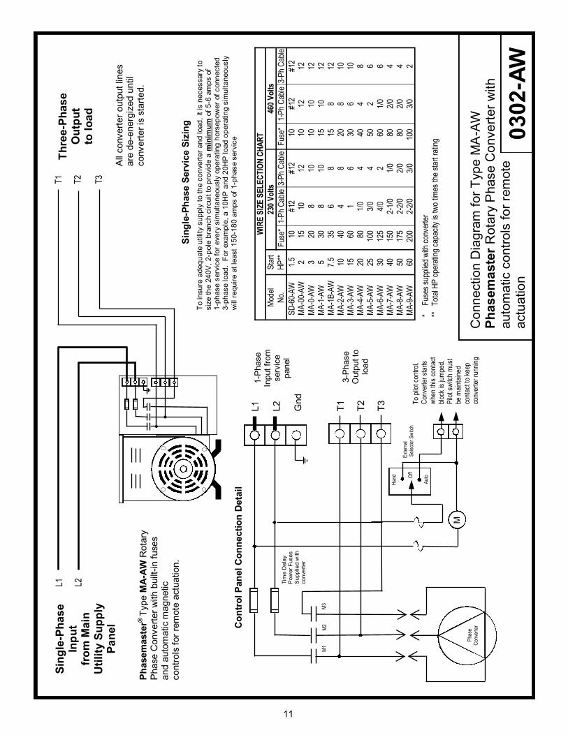
VIII. IN CASE OF TROUBLE
Condition What to look for Corrective action
Converter does not start. No sound.
Check power source with a voltmeter. L-1 to L-2 should read 230 volts (or 460 volts in a
460 volt system. If converter does not make any sound it is probably NOT getting power.
Restore power. Reset main breaker and replace with correct size if too
small.
Check the fuses by removing them and testing with
a continuity checker or ohmmeter. A better test is to look for a voltage reading on the load side of the fuses with the converter turned on.
Replace fuses if needed.
Check for loose terminals. Be sure lugs are not crimped on cable insulation.
Tighten or re-terminate as required.
Converter hums but does not start.
Be sure that no load device is starting with the Phasemaster. The converter should be running before any load is placed on it
Turn off all loads and re-start the Phasemaster®.
Be sure that the incoming single-phase lines (L-1 and L-2) are properly connected to L-1 and L-2 in the converter junction box. Do not connect either
incoming line to T-3 of the converter.
Connect the power source to L-1 and L-2 in the converter. Connect T-3 to the load only.
The converter may have failed capacitors. Each
capacitor should be checked with an ohmmeter or capacitor tester
Replace any capacitors that are
open, bulged or leaking.
Make sure the rotor moves freely by moving it with
a screwdriver or other tool with power off.
Loosen bolts and re-tighten to free
rotor. If rotor does not turn freely after doing this, call factory.
Converter attempts to start and
breaker trips or breaker trips after converter is started and load is added.
Check the single-phase service calculations in
Section III (pg.4) to determine if the breaker feeding the converter is large enough.
Replace with larger breaker if
necessary
Check to be certain of the time-delay characteristics of the breakers. They should have similar characteristics to time delay fuses.
Ordinary household type breakers are not suitable.
Replace with delay type breakers or time delay fuses. Do not oversize the breakers
Load(s) always trip overloads during or shortly after startup
Check the line voltage (L-1 to L-2) with an analog voltmeter during start and determine the amount of
line voltage drop. Check transformer capacity. If the line voltage drops more than 10% of no load line voltage, take corrective action.
Increase supply line cable size and transformer size if required. Your
power company can usually help with transformer problems.
A loud humming noise or chatter comes from the load starting
relay.
Check voltage between L-2 and T-3. If voltage remains below 200 volts (for a 230 volt system) or
185 volts (for a 208 volt system) after the motor starts, the converter is too small for the application.
Contact factory for further assistance or possible exchange.
The manufactured phase T-3 could be connected to the motor starting relay. Check to ensure correct voltage on this relay coil.
Rewire the control coil circuit so that T-3 does not energize the starter coil.
The voltage measured between L-2 and T-3 is about 30-40 volts higher than the line voltage (L-1
to L-2) with no load applied to the Phasemaster®.
This is a normal condition and verifies correct operation of the Phasemaster®. When the load is applied, this voltage will be reduced as the load
increases. No damage will occur to properly connected equipment.
This condition requires no action.
Load does not start or run
properly.
Check the converter output voltages under load
conditions. L1 to L2 should remain within a few volts of 230 or 460. L2 to T3 may drop momentarily below 180 (or 400) but recover to 220
(440) or above.
If the L2 to T3 voltage remains below
210 (420) volts, the converter may be too small for the application. Contact factory for recommendations or
possible exchange.
Excessive noise or vibration. Noise and vibration are usually the result of a
resonance caused by a mounting surface that does not support the converter well. These problems also occur when the converter is bolted tightly to
any surface.
Be sure to remove the converter from
the shipping skid and place it on a substantial floor using the shock absorbing pads supplied with the
converter. Do not bolt the converter to any surface.
The three-phase currents are
not equal.
If the load comes up to its rated load and none of
its three legs exceeds its nameplate F.L.A. rating, there is no problem. If the L1 and L2 legs are significantly higher than the T3 leg (measured at
the load input, not the converter input) then a larger converter or correction capacitors may be required.
Consult with factory to review
application.
Blown fuses in converter or
disconnect switch
Test for failed capacitors. IMPORTANT - SEE NOTE *
Check for wires touching ground, loose fuse holder connections
Replace any failed capacitors,
correct wiring issues, snug-up fuse holder connections
* IMPORTANT! DO NOT ASSUME CAPACITORS ARE DISCHARGED BECAUSE POWER TO
CONVERTER IS OFF. MANUALLY DISCHARGE CAPACITORS BEFORE ATTEMPTING SERVICE.

16
NOTES: (Purchase date, installation or service date, service issues, etc.)
WARRANTY
Kay Industries, Inc. (the manufacturer) guarantees all products of our manufacture against faulty material or workmanship for aperiod of five years from date of installation or 61 months from date of shipment from factory, whichever period first expires. In additionKay Industries will replace all defective bearings regardless of cause for the life of the converter.
Any part that you return to us within this warranty period showing unmistakable defect in material or workmanship will be renewedor replaced at our option F.O.B. factory without charge. The final decision that an original defect existed shall rest with themanufacturer.
The liability is limited to the renewal or replacement of the defective part. In no case will Kay Industries be liable for damage or lossincurred because of interruption of service or for consequential damages, transportation, labor or expense required to repair orreplace defective parts or units.
Kay Industries will not be responsible if its products have been improperly installed in any way. This warranty shall not apply to anyof the manufacturer’s products that must be replaced because of normal wear, that have been subjected to misapplication, misuse,neglect, accident or that have been repaired or altered outside of the manufacturer’s factory unless expressly authorized by themanufacturer.
Corporate OfficeP.O. Box 1323South Bend, IN 46624800-348-5257 • 574-289-5932(fax)www.kayind.com
Western Region OfficeFremont, CA510-656-8766
© Kay Industries, Inc. 2014 Effective 10/1/2014
Related Documents