SCHEDULES (TABLE 1) HORIZONTAL WALL REINFORCING SCHEDULES (TABLE 2) HORIZONTAL WALL REINFORCING SCHEDULES (TABLE 3) HORIZONTAL WALL REINFORCING (in.²/ft.) AREA DEPTH WALL (in.²/ft.) AREA DEPTH WALL (in.²/ft.) AREA DEPTH WALL ( 15 ’Ma x . ) W a ll De p t h Va r i e s ( 15 ’Ma x . ) W a ll De p t h Va r i e s ( 15 ’Ma x . ) W a ll De p t h Va r i e s 07/01/05 232 1 DITCH BOTTOM INLET TYPES C, D, E AND H 6/ 28/ 2012 8: 05: 35 AM REVI SI ON C:\ d\ pr o j ec t s \ s t andar ds \ r o adway \ 00200- s \ 00232- 01. dgn NO. SHEET NO. INDEX r d960r h DESCRIPTION: REVISION LAST 2013 FDOT DESIGN STANDARDS Location Reference Center Of Box Location Reference Center Of Box Location Reference Center Of Box See Index 201 Eyebolts #4 Bars @ 12" Ctrs. (Short Bars) #4 Bars @ 10" Ctrs. Grate See Index 201 Eyebolt @ 12" Ctrs. #4 Bars @ 11" Ctrs. #4 Bars Grate @ 12" Ctrs. #4 Bars See Index 201 Eyebolt @ 12" Ctrs. #4 Bars Grate (See Table 2) Horiz. Wall Reinf. (See Table 3) Horiz. Wall Reinf. PLAN PLAN PLAN SECTION SECTION SECTION TYPE E TYPE D TYPE C WWF MAX. SPACING BARS SCHEDULE WWF MAX. SPACING BARS SCHEDULE WWF BARS MAX. SPACING SCHEDULE 0’-5’ 0’-7.5’ 7.5’-10’ 10’-15’ A12 A6 C6.5 0.20 0.20 0.24 0.37 12" 6" " 2 1 6 8" 5" 5" 6" " 2 1 5 B5.5 0’-6’ 6’-10’ 10’-13’ 10’-15’ A12 A6 A4 0.20 0.20 0.20 0.24 12" 6" 4" 8" 5" 3" 5" B5.5 " 2 1 5 0’-15’ A12 0.20 12" 8" 4’-1" Wall - 36" Pipe 3’-1" Wall - 24" Pipe Recommended Maximum Pipe Size: 4’-6" Wall - 36" Pipe 3’-0" Wall - 24" Pipe Recommended Maximum Pipe Size: enters a 2’-0" wall) 24" Pipe (18" where an 18" pipe 3’-1" Wall - 18" Pipe 2’-0" Wall - Recommended Maximum Pipe Size: 3’-0" Precast 3’-4" C-I-P 5’-1" Precast 5’-5" C-I-P 4’-0" Precast 4’-4" C-I-P 5 ’- 6 " Pr eca s t 5 ’- 10 " C-I- P 6 " 8 " 6" 8" " 4 1 2 6 " 8 " Precast C-I-P " 4 1 2 Precast C-I-P 6" 8" 3’-0" 3’-0" 4 ’- 6 " 4 ’- 6 " " 4 1 2 Precast C-I-P 6" 8" 4’-1" 4’-1" 3 ’- 1 " 3 ’- 1 " 6 " 8 " 6" 8" 4 ’- 1 " Pr eca s t 4 ’- 5 " C-I- P " 4 1 2 8 " 6 " C-I-P Precast 6 " 8 " 3 ’- 1 " 3 ’- 1 " " 4 1 2 Precast C-I-P 6" 8" 2’-0" 2’-0" 6" 8" " 4 1 2 4 ’- 1 " Pr eca s t 4 ’- 5 " C-I- P Precast C-I-P 6 " 8 " 3’-0" Precast 3’-4" C-I-P 2’-0" 2 " 3" Cl. 2 " Cl . 6 " 8 " Precast C-I-P 6 " 8 " Precast C-I-P Cl . 2 " Cl. 3" 4’-1" 5’-1" Precast 5’-5" C-I-P 2 " Precast C-I-P 6 " 8 " 2 " 4’-0" Precast 4’-4" C-I-P 3’-0" 3" Cl. 2 " Cl . " Precast 4 3 3 " C-I-P 4 3 5 " Precast 4 3 3 " C-I-P 4 3 5 " Precast 4 3 3 " C-I-P 4 3 5 " Precast 4 3 3 " C-I-P 4 3 5 " Precast 4 3 3 " C-I-P 4 3 5 " Precast 4 3 3 " C-I-P 4 3 5

Welcome message from author
This document is posted to help you gain knowledge. Please leave a comment to let me know what you think about it! Share it to your friends and learn new things together.
Transcript

SCHEDULES (TABLE 1)
HORIZONTAL WALL REINFORCING
SCHEDULES (TABLE 2)
HORIZONTAL WALL REINFORCING
SCHEDULES (TABLE 3)
HORIZONTAL WALL REINFORCING
(in.†/ft.)
AREA
DEPTH
WALL
(in.†/ft.)
AREA
DEPTH
WALL
(in.†/ft.)
AREA
DEPTH
WALL
(1
5’
Max.)
Wall
Depth
Varie
s
(1
5’
Max.)
Wall
Depth
Varie
s
(1
5’
Max.)
Wall
Depth
Varie
s
07/01/05 232 1
DITCH BOTTOM INLET TYPES C, D, E AND H
6/28/2012
8:0
5:3
5
AM
RE
VISIO
N
C:\
d\projects\standards\road
way\00200-s\00232-01.d
gn
NO.
SHEET
NO.
INDEX
rd960rh
DESCRIPTION:
REVISION
LAST
2013
FDOT DESIGN STANDARDS
Location Reference
Center Of BoxLocation Reference
Center Of Box
Location Reference
Center Of Box
See Index 201
Eyebolts
#4 Bars @ 12" Ctrs.
(Short Bars)
#4 Bars @ 10" Ctrs.
Grate
See Index 201
Eyebolt
@ 12" Ctrs.
#4 Bars
@ 11" Ctrs.
#4 Bars
Grate
@ 12" Ctrs.
#4 Bars
See Index 201
Eyebolt
@ 12" Ctrs.
#4 Bars
Grate
(See Table 2)
Horiz. Wall Reinf.(See Table 3)
Horiz. Wall Reinf.
PLANPLAN PLAN
SECTIONSECTIONSECTION
TYPE ETYPE D
TYPE C
WWF
MAX. SPACING
BARSSCHEDULE
WWF
MAX. SPACING
BARSSCHEDULE
WWFBARS
MAX. SPACINGSCHEDULE
0’-5’
0’-7.5’
7.5’-10’
10’-15’
A12
A6
C6.5
0.20
0.20
0.24
0.37
12"
6"
"216
8"
5"
5"
6"
"215B5.5
0’-6’
6’-10’
10’-13’
10’-15’
A12
A6
A4
0.20
0.20
0.20
0.24
12"
6"
4"
8"
5"
3"
5"B5.5 "215
0’-15’ A12 0.20 12" 8"
4’-1" Wall - 36" Pipe
3’-1" Wall - 24" Pipe
Recommended Maximum Pipe Size:
4’-6" Wall - 36" Pipe
3’-0" Wall - 24" Pipe
Recommended Maximum Pipe Size:
enters a 2’-0" wall)
24" Pipe (18" where an 18" pipe 3’-1" Wall -
18" Pipe2’-0" Wall -
Recommended Maximum Pipe Size:
3’-0" Precast
3’-4" C-I-P5’-1" Precast
5’-5" C-I-P
4’-0" Precast
4’-4" C-I-P
5’-
6"
Precast
5’-
10"
C-I-P
6"
8"
6"
8"
"412
6"
8"
Precast
C-I-P
"412
Precast
C-I-P
6"
8"
3’-0"
3’-0"
4’-
6"
4’-
6"
"412
Precast
C-I-P
6"
8"4’-1"
4’-1"
3’-
1"
3’-
1"
6"
8"
6"
8"
4’-
1"
Precast
4’-
5"
C-I-P
"412
8"
6"
C-I-P
Precast
6"
8"
3’-
1"
3’-
1"
"412
Precast
C-I-P
6"
8"
2’-0"
2’-0"
6"
8"
"4124
’-1"
Precast
4’-
5"
C-I-P
Precast
C-I-P
6"
8"
3’-0" Precast
3’-4" C-I-P
2’-0"
2"
3" Cl.
2"
Cl.
6"
8"
Precast
C-I-P
6"
8"
Precast
C-I-P
Cl.
2"
Cl.
3"
4’-1"
5’-1" Precast
5’-5" C-I-P
2"
Precast
C-I-P
6"
8"
2"
4’-0" Precast
4’-4" C-I-P
3’-0"
3" Cl.
2"
Cl.
" Precast433
" C-I-P435
" Precast433
" C-I-P435 " Precast4
33
" C-I-P435
" Precast433
" C-I-P435
" Precast433
" C-I-P435
" Precast433
" C-I-P435
SCHEDULES (TABLE 4)
HORIZONTAL WALL REINFORCING
SCHEDULES (TABLE 5)
HORIZONTAL WALL REINFORCING
(in.†/ft.)
AREA
DEPTH
WALL(in.†/ft.)
AREA
DEPTH
WALL
07/01/05 232 2
DITCH BOTTOM INLET TYPES C, D, E AND H
6/28/2012
8:0
5:3
7
AM
RE
VISIO
N
C:\
d\projects\standards\road
way\00200-s\00232-02.d
gn
NO.
SHEET
NO.
INDEX
rd960rh
DESCRIPTION:
REVISION
LAST
2013
FDOT DESIGN STANDARDS
� Of
Location Reference
Center Of Box
See Index 201
Eyebolt
Grate
(See Table 4)
Horiz. Wall Reinf.
@ 12" Ctrs.
#4 Bars
(Short Bars)
#4 Bars @ 10" Ctrs.
Grate
Eyebolt See Index 201
(See Table 5)
Horiz. Wall Reinf.
@ 12" Ctrs.
#4 Bars
(Short Bars)
#4 Bars @ 10" Ctrs.
Location Reference
Center Of Box
� Of
PLAN
SECTIONSECTION
PLAN
GENERAL NOTES
TYPE H (4-GRATE INLET)TYPE H (2 & 3-GRATE INLET)
WWF
MAX. SPACING
BARSSCHEDULE
WWF
MAX. SPACING
BARSSCHEDULE
7’-7" Precast
7’-11" C-I-P 9’-9" Precast
10’-1" C-I-P
Pipe Spacing
S
C-I-P
Precast6"
8"
8’-9"
8’-9"
Precast
C-I-P
6"
8"
4’-
0"
Precast
4’-
4"
C-I-P
C-I-P
Precast6"
8"6’-7"
6’-7"6"
8"
4’-
0"
Precast
4’-
4"
C-I-P
Precast
C-I-P
Pipe Spacing
S
6"
8"
3’-
0"
3’-
0"
6"
8"
3" Cl.
2"
Cl.
7’-7" Precast
7’-11" C-I-P
6’-7"
6"
8"
Precast
C-I-P
(1
5’
Max.)
Wall
Depth
Varie
s
Precast
C-I-P
8"
6"
(1
0’
Max.)
Wall
Depth
Varie
s
3" Cl.
2"
Cl.
9’-9" Precast
10’-1" C-I-P
8’-9"
0’-5’
5’-7’
7’-15’
C6.5
0.24
0.37
0.53
" 216
5"
6"
4""214D4.5
B5.5 "215
0’-5’
5’-10’
C3.5 0.37
0.53
3"
4"
"213
"214D4.5
See Sheet 3 of 7.Or 2-24" Pipe (S=3’-5")
1-60" Pipe6’-7" Wall -
24" Pipe3’-0" Wall -
Recommended Maximum Pipe Size:
Or 2-30" Pipe (S=4’-3")
1-78" Pipe8’-9" Wall -
24" Pipe3’-0" Wall -
Recommended Maximum Pipe Size:
"2
12
"2
12
"2
12
"2
12
6"
8"
3’-
0"
3’-
0"
8"
6"

2"
1"
07/01/10 232 3
DITCH BOTTOM INLET TYPES C, D, E AND H
6/28/2012
8:0
5:4
0
AM
RE
VISIO
N
C:\
d\projects\standards\road
way\00200-s\00232-03.d
gn
NO.
SHEET
NO.
INDEX
rd960rh
DESCRIPTION:
REVISION
LAST
2013
FDOT DESIGN STANDARDS
� Of Band
Band
Band
Band
Band
Band
Band Band
Band Band
0" Clearance Over Rivets
Band (Typ.)
(Typ.)
11 Straight Bars
10 Equal Spaces
Band (Typ.)
3’-4"
3’-
4�
"
TYPE H (2-GRATE INLET)
TYPE C
HALF SECTION CAST IRON GRATES
TYPE E TYPE H (3-GRATE INLET) TYPE H (4-GRATE INLET)
TYPE C TYPE D TYPE E
TYPE H (4-GRATE INLET)
STEEL GRATES
GENERAL NOTES
Approx. Weight 235 Lbs. Approx. Weight 465 Lbs. Approx. Weight 725 Lbs. Approx. Weight 967 Lbs.
additional #4 bar above and at each side of pipe opening.
" clearance around pipe opening. Provide one 21Bars to be cut or bent for 1
All reinforcing is Grade 60 bars with 2" min. cover unless otherwise noted. 10.
For supplementary details see Index No. 201.9.
contract unit price for Performance Turf, SY.
Sodding to be used on all inlets not located in paved areas and paid for under 8.
PERMITTED ON INLET TYPE D
CAST IRON GRATE NOT
2’-4"
11" 11" 2"
2"
2""8
12 "2
12
3’-
0"
"2
12
"211
2"
"211
2" 2’-4"
"4
3"
43
1
3’-
0"
"2
12
"211
2"
2"
"2
11
"211 "2
11
2"
"2
12
3’-4"
2"
"4
3
4’-
4"
"4
3 1
"8
12
2"
1’-5"
2"
1’-5"
2"
"212
4’-
4"
"8
13’-
14 S
paces
15 Bars
2’-4"
Approx. Weight 104 Lbs.
"41Bands 2" x
"163" x 4
1Reticuline Bars 1
"41Straight Bars 2"x
"16
54’-
5
21 S
paces
22 Bars
3’-4"
"2
13’-
4
6’-6"
"812
"4312
"2"
1’-
5"
3’-
4"
1’-
5"
2"
"2
12
6’-6"
"43
"212
"2
11
2"
"2
11
2"
3’-
4"
3’-
4" 1’-
5"
2"
1’-
5"
2"
"2
12
2"
"812 "4
31
8’-8"
"43
"212
"2
11
3’-
4"2
""
21
1
2"
8’-8"
Approx. Total Weight 388 Lbs.
"163Banding Bars 2" x
"163" x 4
1Reticuline Bars 1
"41Straight End-Bearing Bars 2" x
Over Rivets (Typ.)
" Clearance 81
"21
"1632’-1"8
72’-1
"21
"872’-1
"21
"872’-1
"1658’-8
"1653’-2"16
53’-2
2 End-Bearing
14 Straight Bars
15 Equal Spaces
2 End-Bearing
14 Straight Bars
15 Equal Spaces
"8
13’-
14 S
paces
15 Bars
NOTE: Steel Grates Are Required On Inlets With Traversable Slots And On Inlets where Bicycle Traffic Is Anticipated.
4’-5"
CAST IRON GRATES
INLETS (PARTIAL) FOR EXISTING INLETS’.
partial. For conversion work and method of payment see ’TRAVERSABLE SLOT
Traversable slots constructed in existing inlets shall be paid for as inlets 7.
Quantities shown are for information only.
traversable slot inlets. Cost to be included in contract unit price for inlets.
non-traversable slots only when called for in the plans; but required on all
Concrete inlet pavement to be used on inlets without slots and inlets with 6.
" radius.41" chamfer or tooled to 4
3All exposed edges and corners shall be 5.
types of pipe must be checked for fit.
Recommended maximum pipe sizes shown are for concrete pipe. Size for other 4.
particular type.
fabrication, or the cast iron grate may be used, unless the plans stipulate the
G grate is specified in the plans, either the steel grate, hot dip galvanized after
non-traversable slots. Subject to the selection described above, when Alternate
Approx. Weight 190 Lbs.
"41Bands 2" x
"163" x 4
1Reticuline Bars 1
"41Straight Bars 2" x
Approx. Weight 215 Lbs.
"41Bands 2" x
"163" x 4
1Reticuline Bars 1
"41Straight Bars 2" x
"163" x 4
1Reticuline Bars 1
"41Straight Bearing Bars 2" x
" 83Straight End-Bearing Bars 2" x
Approx. Total Weight 310 Lbs.
"41Banding Bars 2" x
anticipated. Either cast iron or steel grates may be used on all inlets with
or steel grates may be used on inlets without slots where bicycle traffic is not
Steel grates are to be used on all inlets with traversable slots. Either cast iron
Steel grates are to be used on all inlets where bicycle traffic is anticipated. 3.
traffic.
Traversable slots shall not be used in areas subject to occasional bicycle
Type H. Slots may be constructed at either or both ends as shown on plans.
traversable slots. The traversable slot modification is not adaptable to inlet
located within roadway clear zones and areas subject to pedestrians shall have
debris is a problem inlets should be constructed with slots. Slotted inlets
Inlets subject to minimal debris should be constructed without slots. Where 2.
pavement areas where pedestrians can walk around the inlet.
areas subject to occasional pedestrian traffic such as landscaped areas and
placed in areas subject to any heavy wheel loads. These inlets may be placed in
medians and other areas subject to infrequent traffic loadings but are not to be
These inlets are suitable for bicycle traffic and are to be used in ditches, 1.
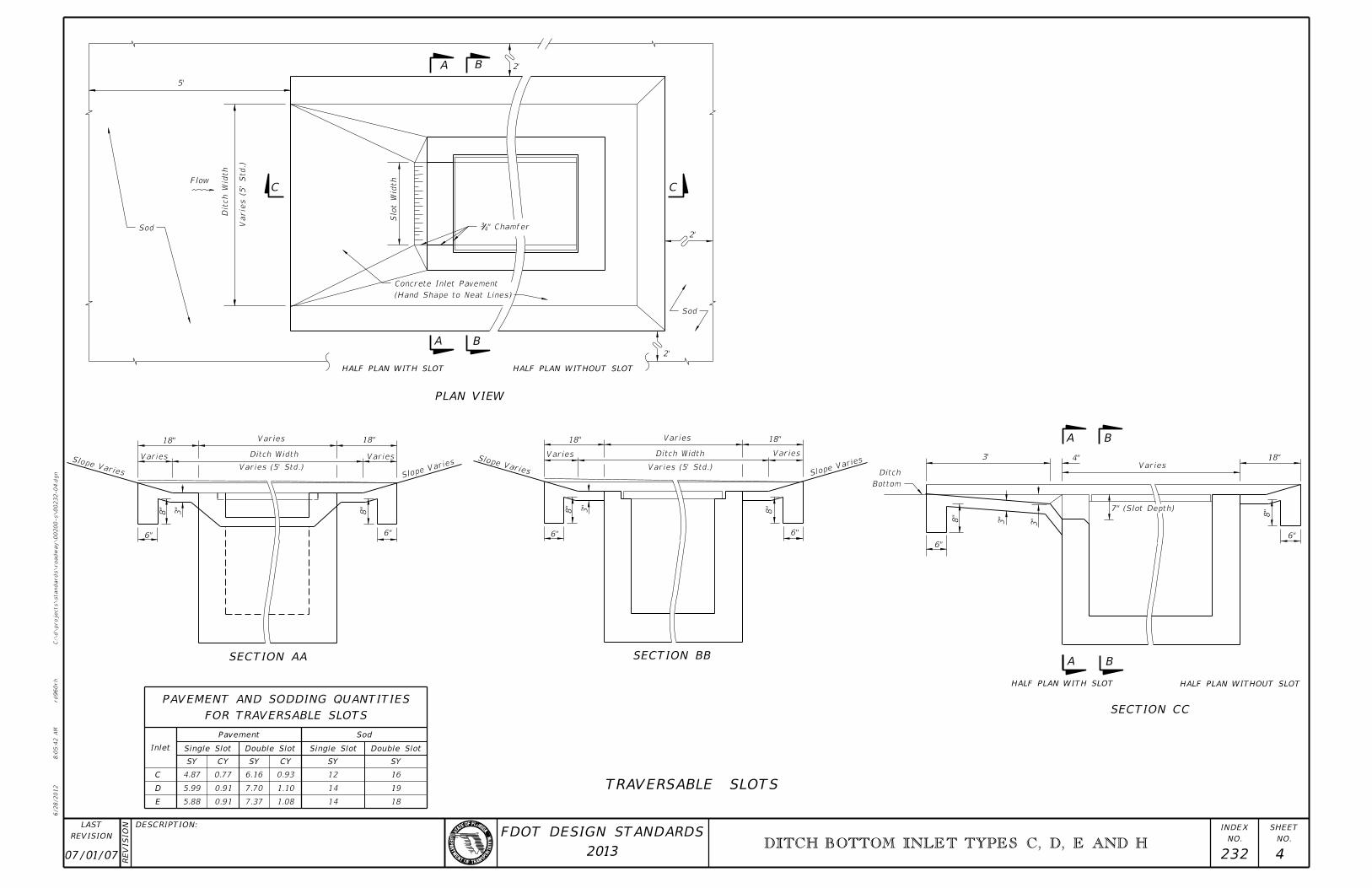
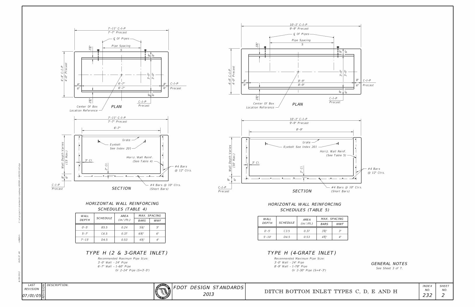
FOR TRAVERSABLE SLOTS
PAVEMENT AND SODDING QUANTITIES
07/01/07 232 4
DITCH BOTTOM INLET TYPES C, D, E AND H
6/28/2012
8:0
5:4
2
AM
RE
VISIO
N
C:\
d\projects\standards\road
way\00200-s\00232-04.d
gn
NO.
SHEET
NO.
INDEX
rd960rh
DESCRIPTION:
REVISION
LAST
2013
FDOT DESIGN STANDARDS
Sod
Sod
(Hand Shape to Neat Lines)
Concrete Inlet Pavement
" Chamfer43
Bottom
Ditch
PLAN VIEW
SECTION AA SECTION BB
SECTION CC
HALF PLAN WITH SLOT HALF PLAN WITHOUT SLOT
HALF PLAN WITH SLOT HALF PLAN WITHOUT SLOT
Inlet Single Slot
Pavement
Double Slot Single Slot
Sod
Double Slot
SY CY SY CY SY SY
C
D
E
TRAVERSABLE SLOTS
C C
A
A B
B
B
BA
A
4.87
5.99
5.88
6.16
7.70
7.37
12
14
16
1814
19
0.77
0.91
0.91
0.93
1.10
1.08
Flow
Ditch
Width
Varie
s (5’
Std.)
Slot
Width
2’
2’
2’
5’
18"
Varies
Varies
Ditch Width
Varies (5’ Std.)
Varies
18"
Slope Varies
6"
8"
3"
8"
6"
Slope
Varies
Slope Varies
6"
8"
3"
Varies
18" Varies
Ditch Width
Varies (5’ Std.)
18"
Varies
Slope
Varies
6"
8"
3’
8"
6"
3"
3"
7" (Slot Depth)
Varies4" 18"
8"
6"
DITCH BLOCK FOR INLETS WITH OR WITHOUT SLOTS
PAVT. AND SOD
SOD ONLYPLAN
SECTION AA SECTION BB
SECTION AA SECTION BB
FOR TRAVERSABLE SLOTS
PAVEMENT AND SODDING QUANTITIES
SYMMETRICAL ABOUT CENTERLINE)
SINGLE SLOT SHOWN (DOUBLE SLOTS
SECTION CC (CASE I)
TRAVERSABLE SLOTS FOR EXISTING INLETS
A A
B
B
A B
A B
Pavement Sod
Double SlotSingle SlotDouble SlotSingle SlotInlet
SY CY SY CY SY SY
C
D
E
(Grate Not Shown)
GRATE SEATS
SIDES WITH
PERMITTED ON
SLOTS NOT
Inlet InletSY
Sod
CY
Pavt.
SY
Sod
4.87
5.99
5.88
6.16
7.70
7.37
12
14
16
1814
19
0.83
1.01
0.99
1.05
1.30
1.24
C
D
E
H
6
6
7
8
0.30
0.36
0.37
0.45 11
9
9
8C
D
H
E
Width Of
Slot
2’
2’
2’
2’
Slope VariesSlo
pe Var
ies Slope Varies Slope
Varies
18"
Varies Ditch Width
Varies
Varies (5’ Std.)
Varies
18"
6"
8"
4"
6"
8"
3"
Varies
Ditch Width
Varies (5’ Std.)
Varies
18" 18"
Varies
6"
8"
3"
8"
6" 6"
8"
3"
4"
3"
4"
5" (Min.)
7" (Slot Depth)
6"
8"
18"Varies
4"
3’
3"
For payment see General Notes Nos. 6 and 7, Sheet 3 of 7.
For plan view and additional details see Sheet 4 of 7.NOTE:
NOTE: See General Notes Nos. 6 and 7, Sheet 3 of 7.
Ditch Bottom
6"
8"
10’
1:20 1:20 Ditch Bottom
Ditch Block (Low Side Of Inlet On Continuous Ditch)
NON-TRAVERSABLE SLOTS
SLOTS AND INLETS WITH NON-TRAVERSABLE SLOTS
SODDING AND PAVEMENT FOR INLETS WITHOUT
00 232 5
DITCH BOTTOM INLET TYPES C, D, E AND H
6/28/2012
8:0
5:4
5
AM
RE
VISIO
N
C:\
d\projects\standards\road
way\00200-s\00232-05.d
gn
NO.
SHEET
NO.
INDEX
rd960rh
DESCRIPTION:
REVISION
LAST
2013
FDOT DESIGN STANDARDS
Slot
Width Of
Plans
Shown On
Otherwise
12" Unless
Slot Depth
Slot
1’-6"
1’-6" Sod
3" Concrete Inlet Pavement
(Paved or Unpaved Ditches)
Toe Wall Required
(Traversable Shown)
Traversable Or Non-traversable
Existing Or Proposed Structure
Pavt. & Slot
Const. Conc. Inlet
Or Without Slots
Exist. Inlet With
Inlet Pavt.
Const. Conc.
Ditch Bottom
Inlet Pavt. & Slot
Const. Conc.
Directed By The Engineer.
In The Plans Or As
Replaced When Called For
Reticuline Grates To Be
Grates. Existing Steel
To Be Replaced With Steel
Existing Cast Iron Grate(s)
Or Without Slots
Exist. Inlet WithEmbedded).
Be Either Removed Or
Rebars In Pavt. Zone May
Wall To This Line (Exposed
Slot Or Remove Exist.
Bottom Of Exist. 12"
�
INLETS (PARTIAL) FOR EXISTING INLETS
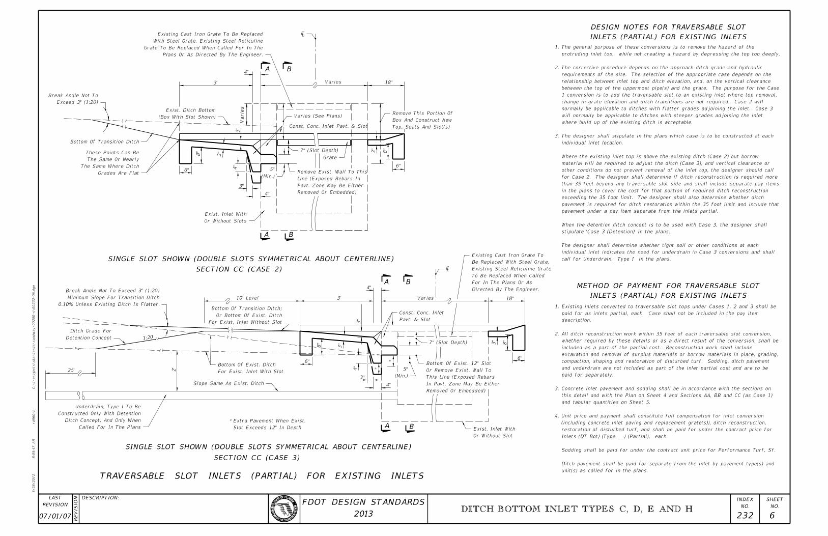
DESIGN NOTES FOR TRAVERSABLE SLOT
SINGLE SLOT SHOWN (DOUBLE SLOTS SYMMETRICAL ABOUT CENTERLINE)
SECTION CC (CASE 2)
SINGLE SLOT SHOWN (DOUBLE SLOTS SYMMETRICAL ABOUT CENTERLINE)
SECTION CC (CASE 3)
INLETS (PARTIAL) FOR EXISTING INLETS
METHOD OF PAYMENT FOR TRAVERSABLE SLOT
A B
A B
A
A B
B
TRAVERSABLE SLOT INLETS (PARTIAL) FOR EXISTING INLETS
call for Underdrain, Type I in the plans.
individual inlet indicates the need for underdrain in Case 3 conversions and shall
The designer shall determine whether tight soil or other conditions at each
stipulate ’Case 3 (Detention)’ in the plans.
When the detention ditch concept is to be used with Case 3, the designer shall
pavement under a pay item separate from the inlets partial.
pavement is required for ditch restoration within the 35 foot limit and include that
exceeding the 35 foot limit. The designer shall also determine whether ditch
in the plans to cover the cost for that portion of required ditch reconstruction
than 35 feet beyond any traversable slot side and shall include separate pay items
for Case 2. The designer shall determine if ditch reconstruction is required more
other conditions do not prevent removal of the inlet top, the designer should call
material will be required to adjust the ditch (Case 3), and vertical clearance or
Where the existing inlet top is above the existing ditch (Case 2) but borrow
individual inlet location.
The designer shall stipulate in the plans which case is to be constructed at each 3.
where build up of the existing ditch is acceptable.
will normally be applicable to ditches with steeper grades adjoining the inlet
normally be applicable to ditches with flatter grades adjoining the inlet. Case 3
change in grate elevation and ditch transitions are not required. Case 2 will
1 conversion is to add the traversable slot to an existing inlet where top removal,
between the top of the uppermost pipe(s) and the grate. The purpose for the Case
relationship between inlet top and ditch elevation, and, on the vertical clearance
requirements of the site. The selection of the appropriate case depends on the
The corrective procedure depends on the approach ditch grade and hydraulic 2.
protruding inlet top, while not creating a hazard by depressing the top too deeply.
The general purpose of these conversions is to remove the hazard of the 1.
unit(s) as called for in the plans.
Ditch pavement shall be paid for separate from the inlet by pavement type(s) and
Sodding shall be paid for under the contract unit price for Performance Turf, SY.
Inlets (DT Bot) (Type __) (Partial), each.
restoration of disturbed turf, and shall be paid for under the contract price for
(including concrete inlet paving and replacement grate(s)), ditch reconstruction,
Unit price and payment shall constitute full compensation for inlet conversion 4.
and tabular quantities on Sheet 5.
this detail and with the Plan on Sheet 4 and Sections AA, BB and CC (as Case 1)
Concrete inlet pavement and sodding shall be in accordance with the sections on 3.
paid for separately.
and underdrain are not included as part of the inlet partial cost and are to be
compaction, shaping and restoration of disturbed turf. Sodding, ditch pavement
excavation and removal of surplus materials or borrow materials in place, grading,
included as a part of the partial cost. Reconstruction work shall include
whether required by these details or as a direct result of the conversion, shall be
All ditch reconstruction work within 35 feet of each traversable slot conversion, 2.
description.
paid for as inlets partial, each. Case shall not be included in the pay item
Existing inlets converted to traversable slot tops under Cases 1, 2 and 3 shall be 1.
4"
3’ Varies 18"
3"
8"
6"
3"
4"
4"
3"
3"
8"
6"
Varie
s
10’ Level
1:20
25’ 2’
3’
3"
4"
8"
3"
6"
4"
3"
4"
Varies 18"
3"
8"
6"
*
*
Slot Exceeds 12" In Depth
Extra Pavement When Exist. *
07/01/07 232 6
DITCH BOTTOM INLET TYPES C, D, E AND H
6/28/2012
8:0
5:4
7
AM
RE
VISIO
N
C:\
d\projects\standards\road
way\00200-s\00232-06.d
gn
NO.
SHEET
NO.
INDEX
rd960rh
DESCRIPTION:
REVISION
LAST
2013
FDOT DESIGN STANDARDS
Exceed 3° (1:20)
Break Angle Not To
Removed Or Embedded)
Pavt. Zone May Be Either
Line (Exposed Rebars In
Remove Exist. Wall To This (Min.)
5"
7" (Slot Depth)
Varies (See Plans)
Top, Seats And Slot(s)
Box And Construct New
Remove This Portion Of
¡
Const. Conc. Inlet Pavt. & Slot
Plans Or As Directed By The Engineer.
Grate To Be Replaced When Called For In The
With Steel Grate. Existing Steel Reticuline
Existing Cast Iron Grate To Be Replaced
(Box With Slot Shown)
Exist. Ditch Bottom
Bottom Of Transition Ditch
Grades Are Flat
The Same Where Ditch
The Same Or Nearly
These Points Can Be
Or Without Slots
Exist. Inlet With
Grate
Detention Concept
Ditch Grade For
For Exist. Inlet With Slot
Bottom Of Exist. Ditch
Slope Same As Exist. Ditch
Called For In The Plans
Ditch Concept, And Only When
Constructed Only With Detention
Underdrain, Type I To Be
Or Without Slot
Exist. Inlet With
For Exist. Inlet Without Slot
Or Bottom Of Exist. Ditch
Bottom Of Transition Ditch;
Pavt. & Slot
Const. Conc. Inlet
¡
Directed By The Engineer.
For In The Plans Or As
To Be Replaced When Called
Existing Steel Reticuline Grate
Be Replaced With Steel Grate.
Existing Cast Iron Grate To
7" (Slot Depth)
(Min.)
5"
Removed Or Embedded)
In Pavt. Zone May Be Either
This Line (Exposed Rebars
Or Remove Exist. Wall To
Bottom Of Exist. 12" Slot
0.10% Unless Existing Ditch Is Flatter.
Minimum Slope For Transition Ditch
Break Angle Not To Exceed 3° (1:20)
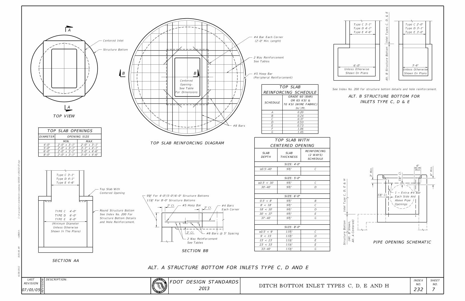
INLETS TYPE C, D & E
ALT. B STRUCTURE BOTTOM FOR
PIPE OPENING SCHEMATIC
SECTION BB
SECTION AA
TOP VIEW
TOP SLAB OPENINGS
CENTERED OPENING
TOP SLAB WITH
REINFORCING SCHEDULE
TOP SLAB
TOP SLAB REINFORCING DIAGRAM
ALT. A STRUCTURE BOTTOM FOR INLETS TYPE C, D AND E
DIAMETER OPENING SIZE
MIN. MAX.
SCHEDULE
In.†/ft.
70 KSI (WIRE FABRIC)
OR 65 KSI &
GRADE 60 (BAR)
DEPTH
SLAB
THICKNESS
SLAB
SCHEDULE
(2 WAYS)
REINFORCING
SIZE: 8’-0"
SIZE: 6’-0"
SIZE: 5’-0"
SIZE: 4’-0"
TYPE C 4’-0"
TYPE D 6’-0"
TYPE E 6’-0"
Shown In The Plans)
Unless Otherwise
(Minimum Diameter
Type E 4’-6"
Type D 4’-1"
Type C 3’-1"
Type E 4’-6"
Type D 4’-1"
Type C 3’-1"
6’-0"
Shown On Plans
Unless Otherwise
Shown On Plans
Unless Otherwise
3’-6"
Type E 3’-0"
Type D 3’-1"
Type C 2’-0"
Inlet Types C,
D,
& E
Alt.
B Structure B
otto
m
See Index No. 200 for structure bottom details and hole reinforcement.
3"
Min.
6"
Min.
6"
Min.
Alt.
A Centered)
(Alt.
B S
ho
wn,
Structure B
otto
mInlet Type C,
D,
E
&
H
" Cl.
21
1
" Cl.211
A
A
B B
For Dimensions
See Table
Opening-
Centered
2" Cl.2" Cl.
2" Cl.
4’-0"
5’-0"
6’-0"
8’-0"
2’-0" x 3’-1"
2’-0" x 3’-1"
2’-0" x 3’-1"
2’-0" x 3’-1"
2’-0" x 3’-1"
3’-1" x 4’-1"
3’-0" x 4’-6"
3’-0" x 4’-6"
A
B
G
F
E
D
C
0.20
0.24
0.37
0.53
0.73
1.06
1.45
C
C
D
E
G
D
C
E
E
G
C
D
B
"2111
"219
"219
"219
"219
"219
"219
"219
"219
"2111
"2111
"2111
"2111
30’-40’
33’-40’
37’-40’
8’ < 18’
18’ < 30’
30’ < 37’
0.5’ < 8’
9’ < 15’
15’ < 23’
23’ < 33’
=0.5’-40’
=0.5’ < 30’
=0.5’ < 9’
07/01/05 232 7
DITCH BOTTOM INLET TYPES C, D, E AND H
6/28/2012
8:0
5:4
9
AM
RE
VISIO
N
C:\
d\projects\standards\road
way\00200-s\00232-07.d
gn
NO.
SHEET
NO.
INDEX
rd960rh
DESCRIPTION:
REVISION
LAST
2013
FDOT DESIGN STANDARDS
Centered Inlet
Structure Bottom
(2’-0" Min. Length)
#4 Bar Each Corner
See Tables
2 Way Reinforcement
(Peripheral Reinforcement)
#5 Hoop Bar
#8 Bars
Openings
Above Pipe
Each Side And
1 ~ Extra #4 Bar
" For 8’-0" Structure Bottoms2111
" For 4’-0"/5’-0"/6’-0" Structure Bottoms219
Centered Opening
Top Slab With
and Hole Reinforcement.
Structure Bottom Details
See Index No. 200 For
Round Structure Bottom
#5 Hoop Bar
Each Corner
#4 Bars
#8 Bars @ 5" Spacing
See Tables
2 Way Reinforcement
Related Documents