INSTALLATION, OPERATION AND MAINTENANCE MANUAL FOR LOW VOLTAGE Active Harmonic Filters Rev. 5, January 27, 2012 Type AHF Active Harmonic Filter User’s Manual 16964 West Victor Road New Berlin, WI 53151 (262) 754-3883 • Fax: (262) 754-3993 Web site: www.artechepq.com

Welcome message from author
This document is posted to help you gain knowledge. Please leave a comment to let me know what you think about it! Share it to your friends and learn new things together.
Transcript
INSTALLATION, OPERATION AND MAINTENANCE MANUAL FOR
LOW VOLTAGE Active Harmonic Filters
Rev. 5, January 27, 2012
Type AHF
Active Harmonic Filter
User’s Manual 16964 West Victor Road New Berlin, WI 53151 (262) 754-3883 • Fax: (262) 754-3993 Web site: www.artechepq.com

INSTALLATION, OPERATION AND MAINTENANCE MANUAL FOR
LOW VOLTAGE Active Harmonic Filters
Rev. 5, January 27, 2012
Page Intentionally Left Blank
User‟s Manual for Type AHF Active Harmonic Filter
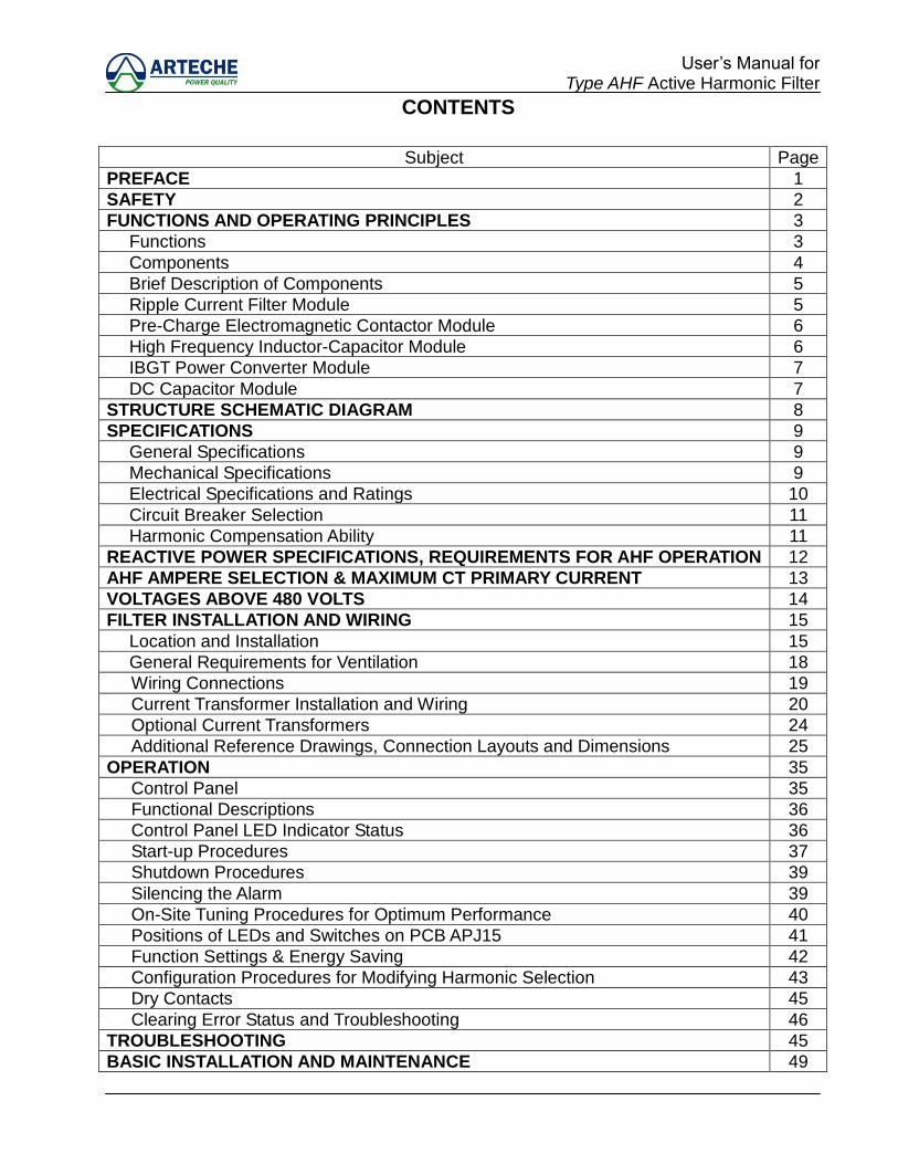
CONTENTS
Subject Page
PREFACE 1
SAFETY 2
FUNCTIONS AND OPERATING PRINCIPLES 3
Functions 3
Components 4
Brief Description of Components 5
Ripple Current Filter Module 5
Pre-Charge Electromagnetic Contactor Module 6
High Frequency Inductor-Capacitor Module 6
IBGT Power Converter Module 7
DC Capacitor Module 7
STRUCTURE SCHEMATIC DIAGRAM 8
SPECIFICATIONS 9
General Specifications 9
Mechanical Specifications 9
Electrical Specifications and Ratings 10
Circuit Breaker Selection 11
Harmonic Compensation Ability 11
REACTIVE POWER SPECIFICATIONS, REQUIREMENTS FOR AHF OPERATION 12
AHF AMPERE SELECTION & MAXIMUM CT PRIMARY CURRENT 13
VOLTAGES ABOVE 480 VOLTS 14
FILTER INSTALLATION AND WIRING 15
Location and Installation 15
General Requirements for Ventilation 18
Wiring Connections 19
Current Transformer Installation and Wiring 20
Optional Current Transformers 24
Additional Reference Drawings, Connection Layouts and Dimensions 25
OPERATION 35
Control Panel 35
Functional Descriptions 36
Control Panel LED Indicator Status 36
Start-up Procedures 37
Shutdown Procedures 39
Silencing the Alarm 39
On-Site Tuning Procedures for Optimum Performance 40
Positions of LEDs and Switches on PCB APJ15 41
Function Settings & Energy Saving 42
Configuration Procedures for Modifying Harmonic Selection 43
Dry Contacts 45
Clearing Error Status and Troubleshooting 46
TROUBLESHOOTING 45
BASIC INSTALLATION AND MAINTENANCE 49

User‟s Manual for Type AHF Active Harmonic Filter
ILLUSTRATION CONTENTS
Drawing 1-1 System Structure Schematic Diagram ..................................................... 8
Drawing 2-1 Install Top Cover of AF-0025&AF-0050 .................................................. 15
Drawing 2-2 Install Top Cover of AF-0100&AF-0150 .................................................. 16
Drawing 2-3 Install Top Cover of AF-0200 .................................................................. 23
Drawing 2-4 2CTs Wiring Schematic Diagram at Load Side ...................................... 23
Drawing 2-5 2CTs Wiring Schematic Diagram at Power Side .................................... 20
Drawing 2-6 AF-0025 & AF-0050 with LCD Control & Dimensions Diagram………….29
Drawing 2-7 AF-0025 & AF-0050 Wiring Position Schematic Diagram ....................... 30
Drawing 2-8 AF-0100 & AF-0150 with LCD Control & Dimensions Diagram .............. 31
Drawing 2-9 AF-0100 & AF-0150 Wiring Position Schematic Diagram ....................... 32
Drawing 2-10 AF-0200 LCD Control & Display Panel Physical Dimensions Diagram .. 33
Drawing 2-11 AF-0200 Wiring Position Schematic Diagram ......................................... 34
Drawing 3-1 Control Panel Diagram ........................................................................... 35
Drawing 3-2 Positions of LEDs and Switches on PCB APJI5 ..................................... 41
Chart 3-2 SW1 Setting (for Harmonic Selection) .................................................... 43
Chart 3-3 Harmonic Compensation Setting Description (SW2 Setting) .................. 44
Chart 3-4 Dry Contacts Description ........................................................................ 45
Drawing 3-3 Positions of Dry Contacts on PCB APJK2 .............................................. 45
1
User‟s Manual for Type AHF Active Harmonic Filter
PREFACE
We thank you for the trust in selecting the ARTECHE Type AHF Active Harmonic Filter. This equipment complies with UL 508 and is authorized to use the UL marking.
The purpose of this user‟s manual is to describe the operating principles for the ARTECHE Active Harmonic Filter and providing users with necessary procedures for the installation and operation of the system.

2
User‟s Manual for Type AHF Active Harmonic Filter
SAFETY
CAUTION!
System installation, operation and maintenance should only be carried out by authorized and trained personnel, adhering to local AND international regulations.
Before any maintenance to the Active Harmonic Filter (AHF), be certain that the power switch is OFF, and wait for at least FIVE minutes to ensure any residual current has been completely discharged from the DC Capacitor Module.
The following precautions should be observed at all times during the installation, operation, maintenance or calibration of the AHF: 1. Ensure the AHF has been properly grounded before the switch is turned on. Poor
grounding will cause malfunction or possible electrical shock. 2. Maintenance should be conducted with care to avoid possible electrical shock. It is
strongly advised that voltage levels of circuits be checked, and that all stored-energy components have been fully discharged before maintenance is performed. Safety goggles should be worn throughout the maintenance process.
3. If the AHF has been incorrectly installed, harmonic current and voltage may be applied
onto the power system resulting in damage to the equipment and other systems. 4. Incorrect operating methods may cause damage to equipment components and
degrade the system‟s performance. 5. An improper shutdown (switch-off) procedure of the AHF may cause damage to the
equipment. See Section – “Shutdown Procedures” in this manual. 6. Replacement of any components or parts should be done by an authorized technician.
DANGER
!
3
User‟s Manual for Type AHF Active Harmonic Filter
FUNCTIONS AND OPERATING PRINCIPLES
FUNCTIONS
The AHF is a solid-state power converter that provides the following advantages:
Minimizes harmonic currents from non-linear loads.
Compensates reactive power factor of lagging loads.
Acts as a virtual damping resistor to prevent possible harmonic resonance. The AHF significantly reduces the upstream harmonic distortion because the AHF is a more attractive source of harmonic currents than the utility power system. The AHF will supply the harmonic currents demanded by the non-linear loads and typically achieves a 10:1 reduction of each individual harmonic. By significantly reducing the harmonic currents in the circuit, there will be 1. No risk of harmonic resonance. 2. Significant reduction of current waveform distortion. 3. Significant reduction of the voltage waveform distortion. 4. Reduction of voltage drop on transformers & cables. 5. Reduction of temperature rise on transformers & cables. 6. Reduced true RMS current. 7. Improved power factor.
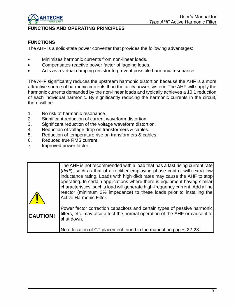
CAUTION!
The AHF is not recommended with a load that has a fast rising current rate (di/dt), such as that of a rectifier employing phase control with extra low inductance rating. Loads with high di/dt rates may cause the AHF to stop operating. In certain applications where there is equipment having similar characteristics, such a load will generate high-frequency current. Add a line reactor (minimum 3% impedance) to these loads prior to installing the Active Harmonic Filter. Power factor correction capacitors and certain types of passive harmonic filters, etc. may also affect the normal operation of the AHF or cause it to shut down. Note location of CT placement found in the manual on pages 22-23.

4
User‟s Manual for Type AHF Active Harmonic Filter
COMPONENTS
The ARTECHE AHF provides three phase harmonic current compensation. The main components of the AHF are as follow:
A ripple current filter module. This module‟s main function is to absorb the high
frequency ripple current. Fixed reactive power is provided by capacitors in the Inductor-Capacitor Module.
A pre-charge electromagnetic contactor module. This module helps to limit the
amplitude of the inrush current when DC capacitor set is charging. A high frequency inductor-capacitor module. This module acts as the power
transmission interface component between power converter and power system. An Isolated Gate Bipolar Transistor (IGBT) power converter module. This module
transforms the harmonic energy from the connected power system and regenerates an equal, but opposite phase shifted harmonic current back to the power system. This regenerated energy will cancel the harmonic produced by the power system.
A DC capacitor module. This module stores energy taken from the power system
before the IGBT Converter can use it to regenerate the opposite phase shifted compensating harmonic current.
(1) High-Speed Fuse
(2) Ripple Current Filter Module
(3) Soft-start Electromagnetic Contactor Module
(4) High Frequency Inductor-Capacitor Module
(5) IGBT Power Converter Module
(6) DC Capacitor Module

5
User‟s Manual for Type AHF Active Harmonic Filter
BRIEF DESCRIPTION OF COMPONENTS
This section describes the working principles of the main components inside the ARTECHE Type AHF Active Harmonic Filter.
RIPPLE CURRENT FILTER MODULE
The ripple current filter is shunt-connected at the output terminals of the AHF. Its primary function is to absorb high frequency ripple current. Its components consist of the following:
Parallel/Series link resonance filter.
Over-current protection relay (OL1).
Abnormal trip control device. The over-current protection relay (OL1) is incorporated to protect the AHF. Either adverse system conditions, interference with VFDs that do not have internal reactors, or a malfunctioning IGBT power converter may generate a large amount of high frequency current into the ripple current filter. This will cause the over-current protection relay to trip, thus shutting down the AHF system to prevent further damage to the entire the AHF system.
6
User‟s Manual for Type AHF Active Harmonic Filter
PRE-CHARGE ELECTROMAGNETIC CONTACTOR MODULE
The main function of this module is to inhibit inrush current while the DC capacitor module is charging. When the voltage of the DC capacitor reaches its default value, the AHF will then be switched on to its normal operating mode, thus removing the pre-charge resistor from the circuit. The main components for pre-charge electromagnetic contactor are as followings:
Current-limiting resistor
Electromagnetic contactor This module inhibits the inrush current going through the IGBT power converter and into the DC capacitor module within a pre-determined and acceptable level. After switching on the AHF, the electromagnetic contactor will close to bypass the current-limiting resistor, and connecting the IGBT power converter directly to the power system.
HIGH FREQUENCY INDUCTOR-CAPACITOR MODULE
The inductor and capacitor are the power transmission interface components between the IGBT power converter and the connected power system. This module also compensates the reactive power to improve the lagging power factor.
The main components of the High Frequency Inductor-Capacitor Module are:
High frequency response inductor.
High frequency response capacitor.
Current transformer.
The current transformer is used to feedback the harmonic compensating current to a control circuit, this will allow the AHF to perform high-speed compensation and ensure a current-limit if the harmonic energy exceeds its capacity.
Under normal working conditions, the ripple current filter will also provide partial reactive power factor to improve lagging power factor. The capacitors in this module supply a fixed amount of reactive power when the filtering is on.
7
User‟s Manual for Type AHF Active Harmonic Filter
IGBT POWER CONVERTER MODULE
The IGBT power converter is the major architecture of the AHF in terms of performing the cancellation of the harmonic current (ILh) generated by the connected non-linear load. The IGBT power converter makes use of this harmonic energy (ILh) as an initial power to produce an opposite phase shifted harmonic current waveform (IE). This waveform is then re-injected into the connected power system to cancel the existing harmonic distortions (ILh), ensuring a near perfect sine waveform (Is) returned to the power system conductors. The main components of the IGBT power converter module are:
IGBT transistor bridge
Driver circuit
Snubbers The electronic bridge of the power converter is made up of isolated gate bipolar transistors (IGBT). It utilizes Pulse Width Modulation (PWM) technology to drive the IGBTs to produce the compensating current waveform. Built in snubbers are used with the IGBTs for protection from spikes when the power converter is in operation.
DC CAPACITOR MODULE
DC capacitor module stores the energy (ILh ) generated by the connected power system to be used by the IGBT power converter for re-generation of the opposite phase shifted compensating harmonic current waveform (IE). The storage and release of energy of the DC capacitor module is electrically control by the IGBT power converter. The DC capacitor module is made up of specific magnitude of capacitance (uF) to supply the required harmonic energy. Multiple DC capacitors are connected electrically in parallel to achieve the total required capacitance.

8
User‟s Manual for Type AHF Active Harmonic Filter
SCHEMATIC DIAGRAM
Drawing 1-1 AHF System Structure Schematic Diagram
9
User‟s Manual for Type AHF Active Harmonic Filter
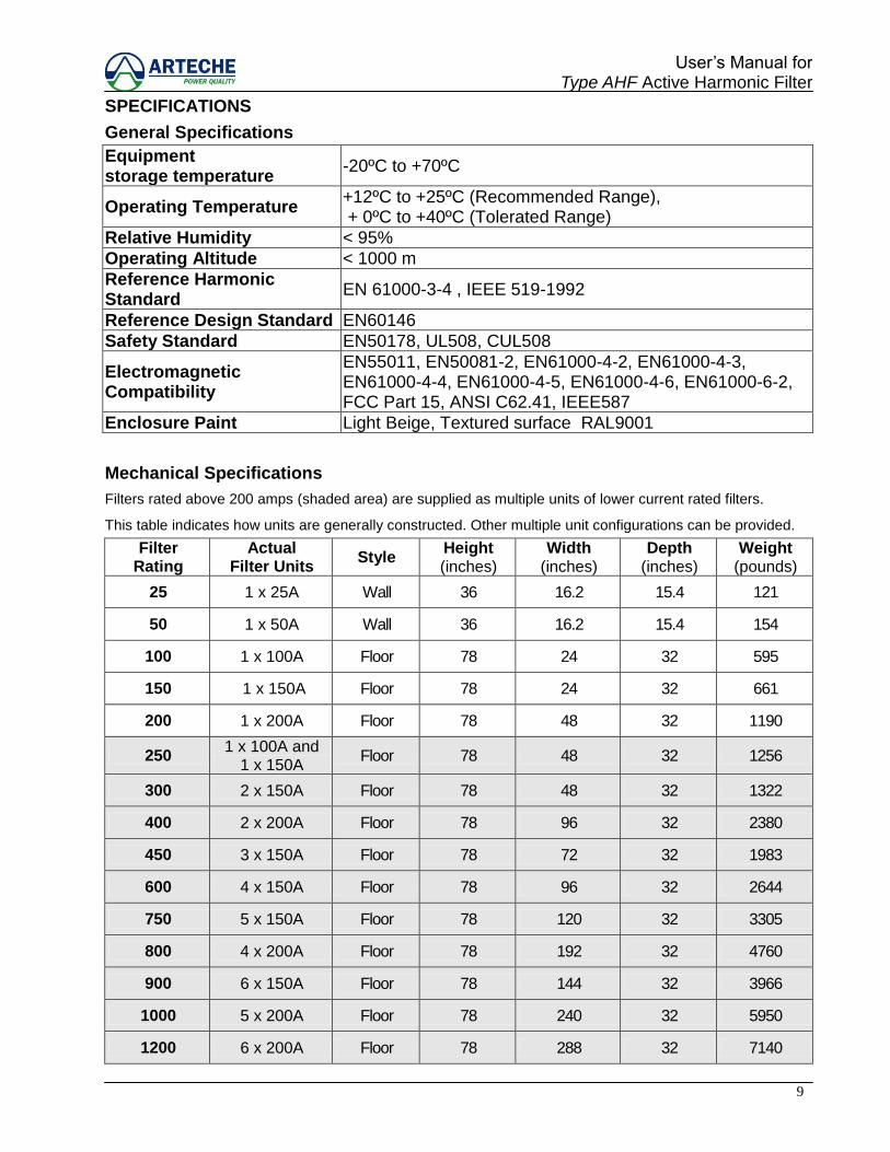
SPECIFICATIONS
General Specifications
Equipment storage temperature
-20ºC to +70ºC
Operating Temperature +12ºC to +25ºC (Recommended Range), + 0ºC to +40ºC (Tolerated Range)
Relative Humidity < 95%
Operating Altitude < 1000 m
Reference Harmonic Standard
EN 61000-3-4 , IEEE 519-1992
Reference Design Standard EN60146
Safety Standard EN50178, UL508, CUL508
Electromagnetic Compatibility
EN55011, EN50081-2, EN61000-4-2, EN61000-4-3, EN61000-4-4, EN61000-4-5, EN61000-4-6, EN61000-6-2, FCC Part 15, ANSI C62.41, IEEE587
Enclosure Paint Light Beige, Textured surface RAL9001
Mechanical Specifications
Filters rated above 200 amps (shaded area) are supplied as multiple units of lower current rated filters.
This table indicates how units are generally constructed. Other multiple unit configurations can be provided.
Filter Rating
Actual Filter Units
Style Height (inches)
Width (inches)
Depth (inches)
Weight (pounds)
25 1 x 25A Wall 36 16.2 15.4 121
50 1 x 50A Wall 36 16.2 15.4 154
100 1 x 100A Floor 78 24 32 595
150 1 x 150A Floor 78 24 32 661
200 1 x 200A Floor 78 48 32 1190
250 1 x 100A and
1 x 150A Floor 78 48 32 1256
300 2 x 150A Floor 78 48 32 1322
400 2 x 200A Floor 78 96 32 2380
450 3 x 150A Floor 78 72 32 1983
600 4 x 150A Floor 78 96 32 2644
750 5 x 150A Floor 78 120 32 3305
800 4 x 200A Floor 78 192 32 4760
900 6 x 150A Floor 78 144 32 3966
1000 5 x 200A Floor 78 240 32 5950
1200 6 x 200A Floor 78 288 32 7140
10
User‟s Manual for Type AHF Active Harmonic Filter
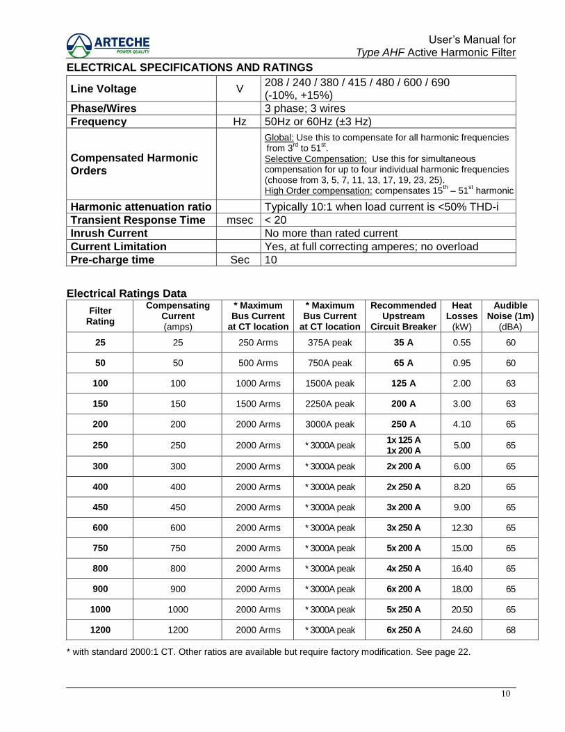
ELECTRICAL SPECIFICATIONS AND RATINGS
Line Voltage V 208 / 240 / 380 / 415 / 480 / 600 / 690 (-10%, +15%)
Phase/Wires 3 phase; 3 wires
Frequency Hz 50Hz or 60Hz (±3 Hz)
Compensated Harmonic Orders
Global: Use this to compensate for all harmonic frequencies from 3
rd to 51
st.
Selective Compensation: Use this for simultaneous compensation for up to four individual harmonic frequencies (choose from 3, 5, 7, 11, 13, 17, 19, 23, 25). High Order compensation: compensates 15
th – 51
st harmonic
Harmonic attenuation ratio Typically 10:1 when load current is <50% THD-i
Transient Response Time msec < 20
Inrush Current No more than rated current
Current Limitation Yes, at full correcting amperes; no overload
Pre-charge time Sec 10
Electrical Ratings Data
Filter Rating
Compensating Current (amps)
* Maximum Bus Current
at CT location
* Maximum Bus Current
at CT location
Recommended Upstream
Circuit Breaker
Heat Losses
(kW)
Audible Noise (1m)
(dBA)
25 25 250 Arms 375A peak 35 A 0.55 60
50 50 500 Arms 750A peak 65 A 0.95 60
100 100 1000 Arms 1500A peak 125 A 2.00 63
150 150 1500 Arms 2250A peak 200 A 3.00 63
200 200 2000 Arms 3000A peak 250 A 4.10 65
250 250 2000 Arms * 3000A peak 1x 125 A 1x 200 A
5.00 65
300 300 2000 Arms * 3000A peak 2x 200 A 6.00 65
400 400 2000 Arms * 3000A peak 2x 250 A 8.20 65
450 450 2000 Arms * 3000A peak 3x 200 A 9.00 65
600 600 2000 Arms * 3000A peak 3x 250 A 12.30 65
750 750 2000 Arms * 3000A peak 5x 200 A 15.00 65
800 800 2000 Arms * 3000A peak 4x 250 A 16.40 65
900 900 2000 Arms * 3000A peak 6x 200 A 18.00 65
1000 1000 2000 Arms * 3000A peak 5x 250 A 20.50 65
1200 1200 2000 Arms * 3000A peak 6x 250 A 24.60 68
* with standard 2000:1 CT. Other ratios are available but require factory modification. See page 22.
11
User‟s Manual for Type AHF Active Harmonic Filter
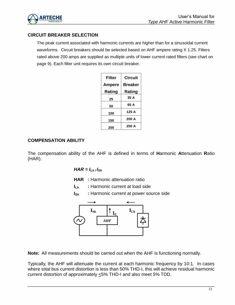
CIRCUIT BREAKER SELECTION
The peak current associated with harmonic currents are higher than for a sinusoidal current
waveforms. Circuit breakers should be selected based on AHF ampere rating X 1.25. Filters
rated above 200 amps are supplied as multiple units of lower current rated filters (see chart on
page 9). Each filter unit requires its own circuit breaker.
Filter
Ampere
Rating
Circuit
Breaker
Rating
25 35 A
50 65 A
100 125 A
150 200 A
200 250 A
COMPENSATION ABILITY
The compensation ability of the AHF is defined in terms of Harmonic Attenuation Ratio (HAR).
HAR = ILh / ISh
HAR : Harmonic attenuation ratio
ILh : Harmonic current at load side
ISh : Harmonic current at power source side
Note: All measurements should be carried out when the AHF is functioning normally.
Typically, the AHF will attenuate the current at each harmonic frequency by 10:1. In cases where total bus current distortion is less than 50% THD-I, this will achieve residual harmonic current distortion of approximately <5% THD-I and also meet 5% TDD.
AHF
ISh ILh IE
12
User‟s Manual for Type AHF Active Harmonic Filter
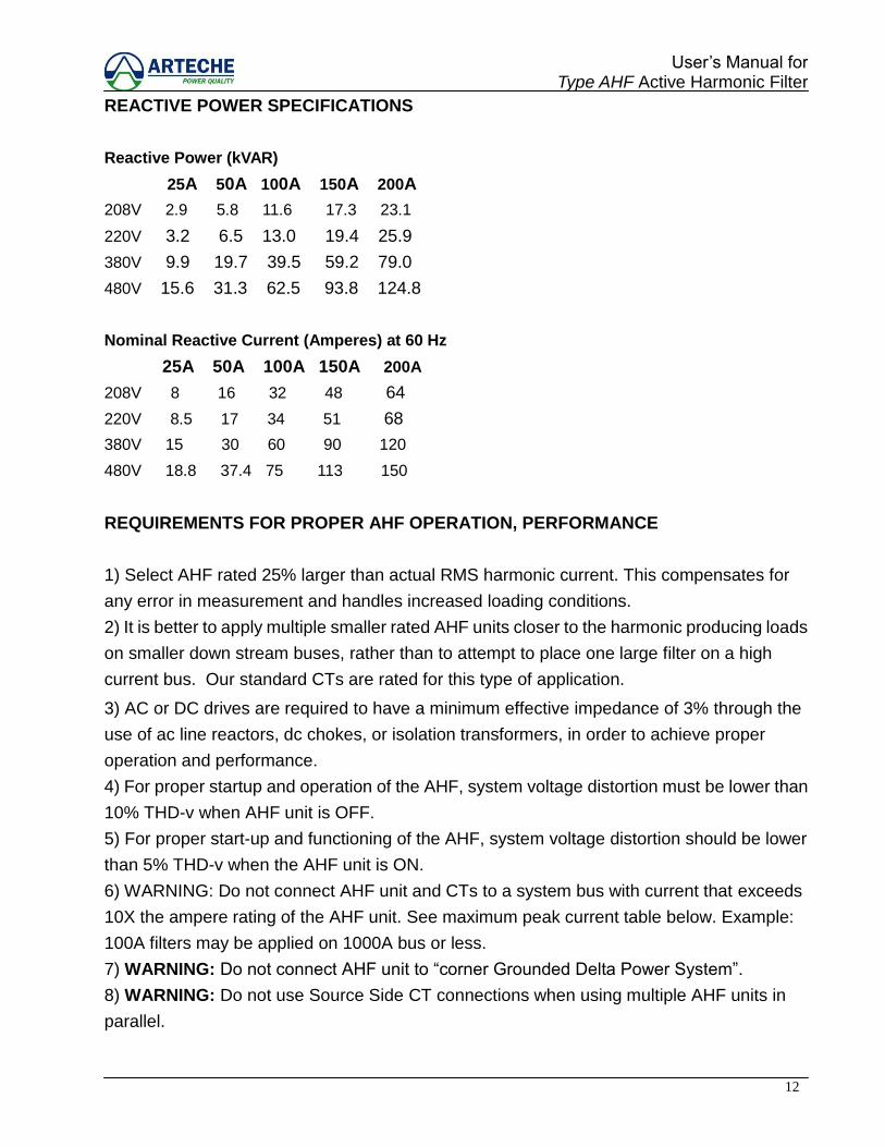
REACTIVE POWER SPECIFICATIONS
Reactive Power (kVAR)
25A 50A 100A 150A 200A
208V 2.9 5.8 11.6 17.3 23.1
220V 3.2 6.5 13.0 19.4 25.9
380V 9.9 19.7 39.5 59.2 79.0
480V 15.6 31.3 62.5 93.8 124.8
Nominal Reactive Current (Amperes) at 60 Hz
25A 50A 100A 150A 200A
208V 8 16 32 48 64
220V 8.5 17 34 51 68
380V 15 30 60 90 120
480V 18.8 37.4 75 113 150
REQUIREMENTS FOR PROPER AHF OPERATION, PERFORMANCE
1) Select AHF rated 25% larger than actual RMS harmonic current. This compensates for
any error in measurement and handles increased loading conditions.
2) It is better to apply multiple smaller rated AHF units closer to the harmonic producing loads
on smaller down stream buses, rather than to attempt to place one large filter on a high
current bus. Our standard CTs are rated for this type of application.
3) AC or DC drives are required to have a minimum effective impedance of 3% through the
use of ac line reactors, dc chokes, or isolation transformers, in order to achieve proper
operation and performance.
4) For proper startup and operation of the AHF, system voltage distortion must be lower than
10% THD-v when AHF unit is OFF.
5) For proper start-up and functioning of the AHF, system voltage distortion should be lower
than 5% THD-v when the AHF unit is ON.
6) WARNING: Do not connect AHF unit and CTs to a system bus with current that exceeds
10X the ampere rating of the AHF unit. See maximum peak current table below. Example:
100A filters may be applied on 1000A bus or less.
7) WARNING: Do not connect AHF unit to “corner Grounded Delta Power System”.
8) WARNING: Do not use Source Side CT connections when using multiple AHF units in
parallel.
13
User‟s Manual for Type AHF Active Harmonic Filter
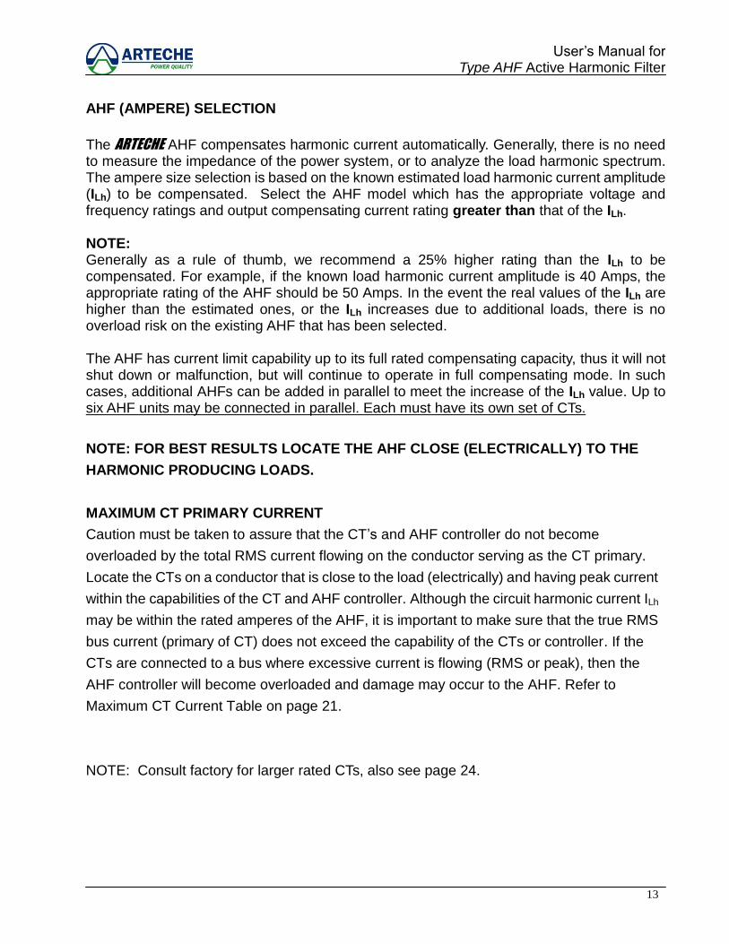
AHF (AMPERE) SELECTION
The ARTECHE AHF compensates harmonic current automatically. Generally, there is no need to measure the impedance of the power system, or to analyze the load harmonic spectrum. The ampere size selection is based on the known estimated load harmonic current amplitude (ILh) to be compensated. Select the AHF model which has the appropriate voltage and frequency ratings and output compensating current rating greater than that of the ILh. NOTE: Generally as a rule of thumb, we recommend a 25% higher rating than the ILh to be compensated. For example, if the known load harmonic current amplitude is 40 Amps, the appropriate rating of the AHF should be 50 Amps. In the event the real values of the ILh are higher than the estimated ones, or the ILh increases due to additional loads, there is no overload risk on the existing AHF that has been selected. The AHF has current limit capability up to its full rated compensating capacity, thus it will not shut down or malfunction, but will continue to operate in full compensating mode. In such cases, additional AHFs can be added in parallel to meet the increase of the ILh value. Up to six AHF units may be connected in parallel. Each must have its own set of CTs.
NOTE: FOR BEST RESULTS LOCATE THE AHF CLOSE (ELECTRICALLY) TO THE
HARMONIC PRODUCING LOADS.
MAXIMUM CT PRIMARY CURRENT
Caution must be taken to assure that the CT‟s and AHF controller do not become
overloaded by the total RMS current flowing on the conductor serving as the CT primary.
Locate the CTs on a conductor that is close to the load (electrically) and having peak current
within the capabilities of the CT and AHF controller. Although the circuit harmonic current ILh
may be within the rated amperes of the AHF, it is important to make sure that the true RMS
bus current (primary of CT) does not exceed the capability of the CTs or controller. If the
CTs are connected to a bus where excessive current is flowing (RMS or peak), then the
AHF controller will become overloaded and damage may occur to the AHF. Refer to
Maximum CT Current Table on page 21.
NOTE: Consult factory for larger rated CTs, also see page 24.
14
User‟s Manual for Type AHF Active Harmonic Filter
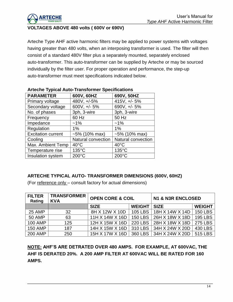
VOLTAGES ABOVE 480 volts ( 600V or 690V)
Arteche Type AHF active harmonic filters may be applied to power systems with voltages
having greater than 480 volts, when an interposing transformer is used. The filter will then
consist of a standard 480V filter plus a separately mounted, separately enclosed
auto-transformer. This auto-transformer can be supplied by Arteche or may be sourced
individually by the filter user. For proper operation and performance, the step-up
auto-transformer must meet specifications indicated below.
Arteche Typical Auto-Transformer Specifications
PARAMETER 600V, 60HZ 690V, 50HZ
Primary voltage 480V, +/-5% 415V, +/- 5%
Secondary voltage 600V, +/- 5% 690V, +/- 5%
No. of phases 3ph, 3-wire 3ph, 3-wire
Frequency 60 Hz 50 Hz
Impedance ~1% ~1%
Regulation 1% 1%
Excitation current ~5% (10% max) ~5% (10% max)
Cooling Natural convection Natural convection
Max. Ambient Temp 40°C 40°C
Temperature rise 135°C 135°C
Insulation system 200°C 200°C
ARTECHE TYPICAL AUTO- TRANSFORMER DIMENSIONS (600V, 60HZ)
(For reference only – consult factory for actual dimensions)
FILTER Rating
TRANSFORMER KVA
OPEN CORE & COIL N1 & N3R ENCLOSED
SIZE WEIGHT SIZE WEIGHT
25 AMP 32 8H X 12W X 10D 105 LBS 18H X 14W X 14D 150 LBS
50 AMP 63 11H X 14W X 16D 150 LBS 26H X 18W X 18D 195 LBS
100 AMP 125 12H X 15W X 16D 220 LBS 28H X 18W X 18D 275 LBS
150 AMP 187 14H X 15W X 16D 310 LBS 34H X 24W X 20D 430 LBS
200 AMP 250 15H X 17W X 16D 360 LBS 34H X 24W X 20D 515 LBS
NOTE: AHF’S ARE DETRATED OVER 480 AMPS. FOR EXAMPLE, AT 600VAC, THE
AHF IS DERATED 20%. A 200 AMP FILTER AT 600VAC WILL BE RATED FOR 160
AMPS.
15
User‟s Manual for Type AHF Active Harmonic Filter
INSTALLATION AND WIRING
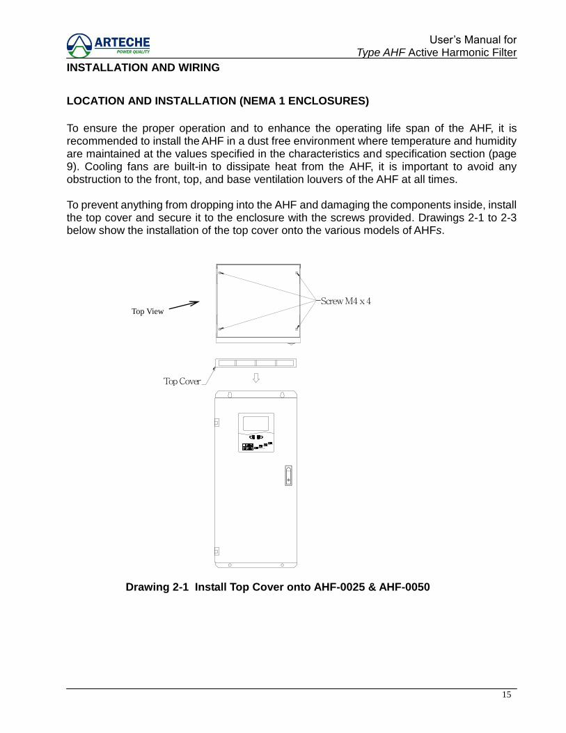
LOCATION AND INSTALLATION (NEMA 1 ENCLOSURES)
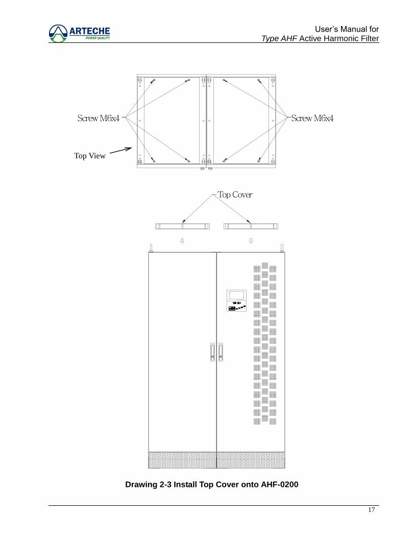
To ensure the proper operation and to enhance the operating life span of the AHF, it is recommended to install the AHF in a dust free environment where temperature and humidity are maintained at the values specified in the characteristics and specification section (page 9). Cooling fans are built-in to dissipate heat from the AHF, it is important to avoid any obstruction to the front, top, and base ventilation louvers of the AHF at all times. To prevent anything from dropping into the AHF and damaging the components inside, install the top cover and secure it to the enclosure with the screws provided. Drawings 2-1 to 2-3 below show the installation of the top cover onto the various models of AHFs.
Screw M4 x 4
ON/OFF
ESCFILTERING
ERRORCORRECTINGFULL
POWER ON
RESET
Top Cover
Screw M4 x 4
Drawing 2-1 Install Top Cover onto AHF-0025 & AHF-0050
Top View
16
User‟s Manual for Type AHF Active Harmonic Filter
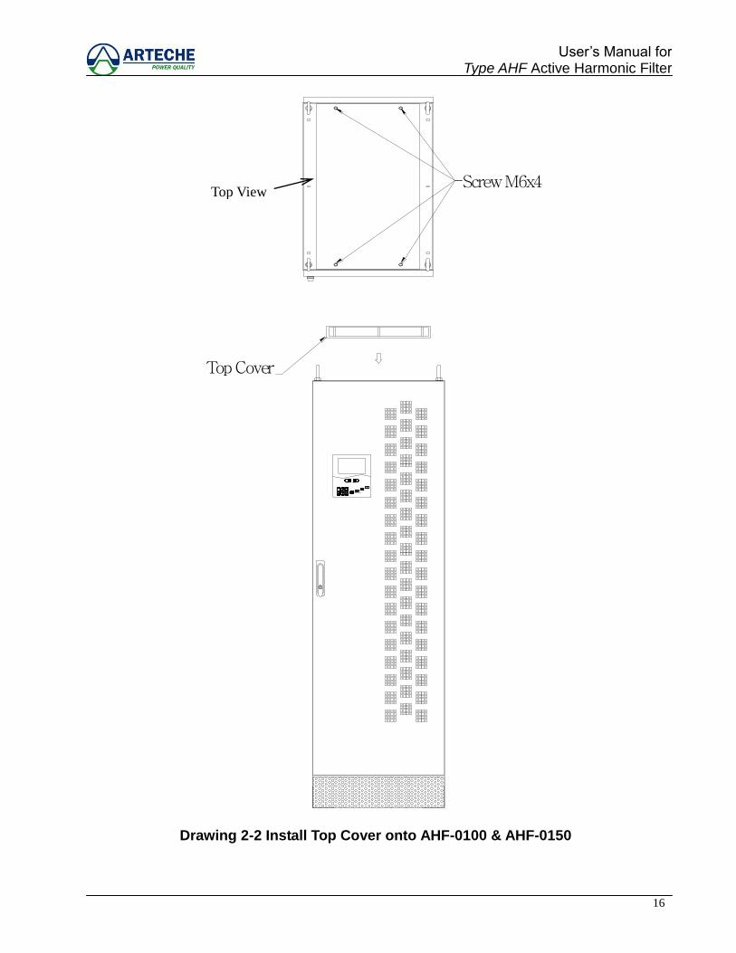
Screw M6x4
Top Cover
Screw M6x4
FILTERING
ESC
ERROR
FULLCORRECTING
POWER ON
RESETON/OFF
Drawing 2-2 Install Top Cover onto AHF-0100 & AHF-0150
Top View
17
User‟s Manual for Type AHF Active Harmonic Filter
Screw M6x4Screw M6x4
Top Cover
Screw M6x4Screw M6x4
ON/OFF
ESC POWER ON
CORRECTINGERROR
FULL
FILTERING
RESET
Drawing 2-3 Install Top Cover onto AHF-0200
Top View
18
User‟s Manual for Type AHF Active Harmonic Filter
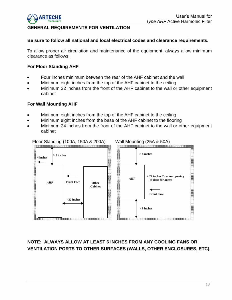
GENERAL REQUIREMENTS FOR VENTILATION
Be sure to follow all national and local electrical codes and clearance requirements. To allow proper air circulation and maintenance of the equipment, always allow minimum clearance as follows: For Floor Standing AHF
Four inches minimum between the rear of the AHF cabinet and the wall
Minimum eight inches from the top of the AHF cabinet to the ceiling
Minimum 32 inches from the front of the AHF cabinet to the wall or other equipment cabinet
For Wall Mounting AHF
Minimum eight inches from the top of the AHF cabinet to the ceiling
Minimum eight inches from the base of the AHF cabinet to the flooring
Minimum 24 inches from the front of the AHF cabinet to the wall or other equipment cabinet
Floor Standing (100A, 150A & 200A)
4 inches
>32 inches
> 8 inches
AHF
Other
Cabinet
Wall Mounting (25A & 50A)
> 24 inches To allow opening
of door for access
> 8 inches
> 8 inches
Front Face
AHF
NOTE: ALWAYS ALLOW AT LEAST 6 INCHES FROM ANY COOLING FANS OR
VENTILATION PORTS TO OTHER SURFACES (WALLS, OTHER ENCLOSURES, ETC).
Front Face
19
User‟s Manual for Type AHF Active Harmonic Filter
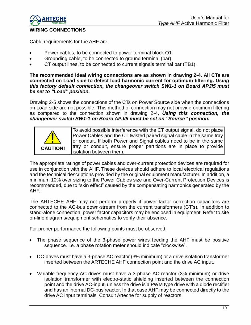
WIRING CONNECTIONS
Cable requirements for the AHF are: Power cables, to be connected to power terminal block Q1. Grounding cable, to be connected to ground terminal (bar). CT output lines, to be connected to current signals terminal bar (TB1). The recommended ideal wiring connections are as shown in drawing 2-4. All CTs are connected on Load side to detect load harmonic current for optimum filtering. Using this factory default connection, the changeover switch SW1-1 on Board APJI5 must be set to “Load” position. Drawing 2-5 shows the connections of the CTs on Power Source side when the connections on Load side are not possible. This method of connection may not provide optimum filtering as compared to the connection shown in drawing 2-4. Using this connection, the changeover switch SW1-1 on Board APJI5 must be set on “Source” position.
CAUTION!
To avoid possible interference with the CT output signal, do not place Power Cables and the CT twisted paired signal cable in the same tray or conduit. If both Power and Signal cables need to be in the same tray or conduit, ensure proper partitions are in place to provide isolation between them.
The appropriate ratings of power cables and over-current protection devices are required for use in conjunction with the AHF. These devices should adhere to local electrical regulations and the technical descriptions provided by the original equipment manufacturer. In addition, a minimum 10% over sizing to the Power Cables size and Over-Current Protection Devices is recommended, due to “skin effect” caused by the compensating harmonics generated by the AHF. The ARTECHE AHF may not perform properly if power-factor correction capacitors are connected to the AC-bus down-stream from the current transformers (CT‟s). In addition to stand-alone connection, power factor capacitors may be enclosed in equipment. Refer to site on-line diagrams/equipment schematics to verify their absence. For proper performance the following points must be observed: The phase sequence of the 3-phase power wires feeding the AHF must be positive
sequence. i.e. a phase rotation meter should indicate “clockwise”. DC-drives must have a 3-phase AC reactor (3% minimum) or a drive isolation transformer
inserted between the ARTECHE AHF connection point and the drive AC input.
Variable-frequency AC-drives must have a 3-phase AC reactor (3% minimum) or drive isolation transformer with electro-static shielding inserted between the connection point and the drive AC-input, unless the drive is a PWM type drive with a diode rectifier and has an internal DC-bus reactor. In that case AHF may be connected directly to the drive AC input terminals. Consult Arteche for supply of reactors.
20
User‟s Manual for Type AHF Active Harmonic Filter
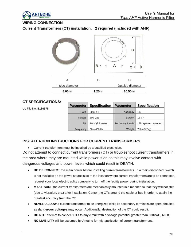
WIRING CONNECTION
Current Transformers (CT) installation: 2 required (included with AHF)
A
Inside diameter
B C
Outside diameter
8.00 in 1.25 in 10.50 in
CT SPECIFICATIONS:
UL File No. E186575
INSTALLATION INSTRUCTIONS FOR CURRENT TRANSFORMERS
Current transformers must be installed by a qualified electrician.
Do not attempt to connect current transformers (CT) or troubleshoot current transformers in
the area where they are mounted while power is on as this may involve contact with
dangerous voltages and power levels which could result in DEATH.
DO DISCONNECT the main power before installing current transformers. If a main disconnect switch
is not available on the power source side of the location where current transformers are to be connected,
request your local electric utility company to turn off the facility power during installation.
MAKE SURE the current transformers are mechanically mounted in a manner so that they will not shift
(due to vibration, etc.) after installation. Center the CTs around the cable or bus in order to attain the
greatest accuracy from the CT.
NEVER ALLOW a current transformer to be energized while its secondary terminals are open-circuited
as dangerous voltages may occur. Additionally, destruction of the CT could result.
DO NOT attempt to connect CTs to any circuit with a voltage potential greater than 600VAC, 60Hz.
NO LIABILITY will be assumed by Arteche for mis-application of current transformers.
Parameter Specification Parameter Specification
Ratio 2000 : 1 Accuracy 1%
Voltage 600 Vac Burden 18 VA
BIL 10kV (full wave) Secondary Leads 12ft; spade connecters
Frequency 50 – 400 Hz Weight 7 lbs (3.2kg)
21
User‟s Manual for Type AHF Active Harmonic Filter
WIRING CONNECTION
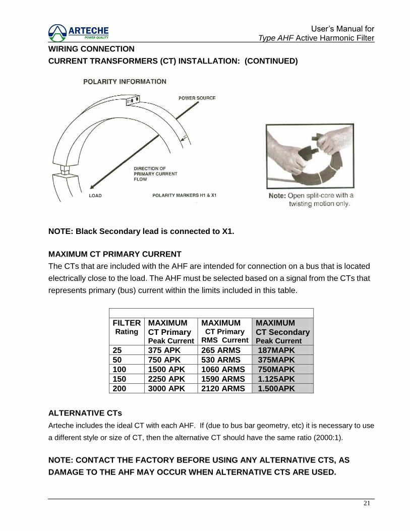
CURRENT TRANSFORMERS (CT) INSTALLATION: (CONTINUED)
NOTE: Black Secondary lead is connected to X1.
MAXIMUM CT PRIMARY CURRENT
The CTs that are included with the AHF are intended for connection on a bus that is located
electrically close to the load. The AHF must be selected based on a signal from the CTs that
represents primary (bus) current within the limits included in this table.
FILTER Rating
MAXIMUM CT Primary Peak Current
MAXIMUM CT Primary
RMS Current
MAXIMUM CT Secondary Peak Current
25 375 APK 265 ARMS 187MAPK
50 750 APK 530 ARMS 375MAPK
100 1500 APK 1060 ARMS 750MAPK
150 2250 APK 1590 ARMS 1.125APK
200 3000 APK 2120 ARMS 1.500APK
ALTERNATIVE CTs
Arteche includes the ideal CT with each AHF. If (due to bus bar geometry, etc) it is necessary to use
a different style or size of CT, then the alternative CT should have the same ratio (2000:1).
NOTE: CONTACT THE FACTORY BEFORE USING ANY ALTERNATIVE CTS, AS
DAMAGE TO THE AHF MAY OCCUR WHEN ALTERNATIVE CTS ARE USED.

22
User‟s Manual for Type AHF Active Harmonic Filter
WIRING CONNECTION - OPTIONAL CT LOCATIONS
VFD
M
3
4
21
VFD
M
VFD
M
MMM
VFD
M Type AHF active harmonic filters are intended to be connected on a bus that is close to the harmonic
producing load(s). To check the suitability of a particular conductor for CT connection, measure the
true RMS and peak currents in the conductor (prior to installing the CT) and check the maximum
allowable RMS and peak current in the table on page 13, for the respective AHF rating. Both the
RMS and peak currents must be within the maximum limits stated in this table. Consult factory for
tie-bus arrangements and utility/generator bus arrangements for additional information.
CAUTION: Measure the current on the intended CT primary bus conductor prior to installing
CT. Confirm that measured current is within the limits stated in the table on page 21.
Optional Locations for connection of AHF and CTs:
1) This is the preferred connection method. Confirm that bus current is within RMS and peak
limits of AHF as per table on page 13.
2) This method of connection can be acceptable if the peak and RMS current in primary of CT is
within the limits in the table on page 13. If CT primary current will be too high, change to method 1).
3) This method of CT connection is only possible if the AHF rating is high enough so that the CT
primary current (RMS and peak) is lower than the limits for the respective AHF in the table on page
13. If CT primary current will be too high, change to method 1).
4) This connection method can rarely be used due to typical bus current ratings. Measure the RMS
and peak current on the primary conduct Confirm that bus current is within RMS and peak limits of
AHF as per table on page 13. If CT primary current will be too high, change to method 1).
23
User‟s Manual for Type AHF Active Harmonic Filter
X1
CTAX2
Break Switch Q1
A B C
X2
Phase A
Phase B
Phase C
SOURCEPOWER
CTCX1
TB
CTAX1 CTCX2
X1 X2 X1
CTA
CTC
X1
X2
X2
Phase C
Phase B
Phase A
LOAD
Enersine DE
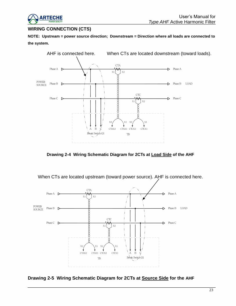
WIRING CONNECTION (CTS)
NOTE: Upstream = power source direction; Downstream = Direction where all loads are connected to
the system.
AHF is connected here. When CTs are located downstream (toward loads).
Drawing 2-4 Wiring Schematic Diagram for 2CTs at Load Side of the AHF
When CTs are located upstream (toward power source). AHF is connected here.
Drawing 2-5 Wiring Schematic Diagram for 2CTs at Source Side for the AHF
CTC
X2
CTAX2 CTAX1
TB
CTCX2
X2X1
Phase A
Phase B
Phase C
SOURCEPOWER
CTA
X1
X2X1
Break Switch Q1
CTCX1 A B
X1
C
X2
Phase C
Phase B
Phase A
LOAD
Enersine DE
24
User‟s Manual for Type AHF Active Harmonic Filter
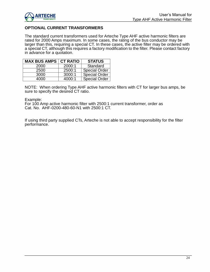
OPTIONAL CURRENT TRANSFORMERS The standard current transformers used for Arteche Type AHF active harmonic filters are rated for 2000 Amps maximum. In some cases, the rating of the bus conductor may be larger than this, requiring a special CT. In these cases, the active filter may be ordered with a special CT, although this requires a factory modification to the filter. Please contact factory in advance for a quotation. MAX BUS AMPS CT RATIO STATUS
2000 2000:1 Standard 2500 2500:1 Special Order 3000 3000:1 Special Order 4000 4000:1 Special Order
NOTE: When ordering Type AHF active harmonic filters with CT for larger bus amps, be sure to specify the desired CT ratio. Example: For 100 Amp active harmonic filter with 2500:1 current transformer, order as Cat. No. AHF-0200-480-60-N1 with 2500:1 CT. If using third party supplied CTs, Arteche is not able to accept responsibility for the filter performance.
25
User‟s Manual for Type AHF Active Harmonic Filter
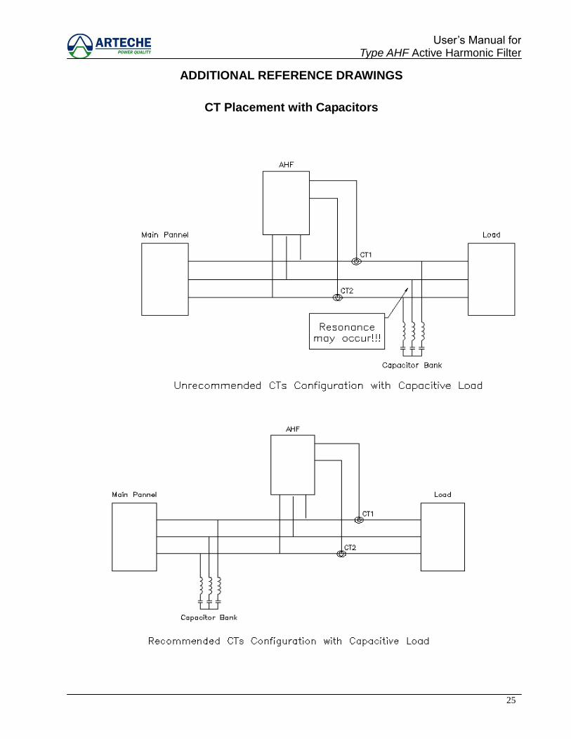
ADDITIONAL REFERENCE DRAWINGS
CT Placement with Capacitors
26
User‟s Manual for Type AHF Active Harmonic Filter
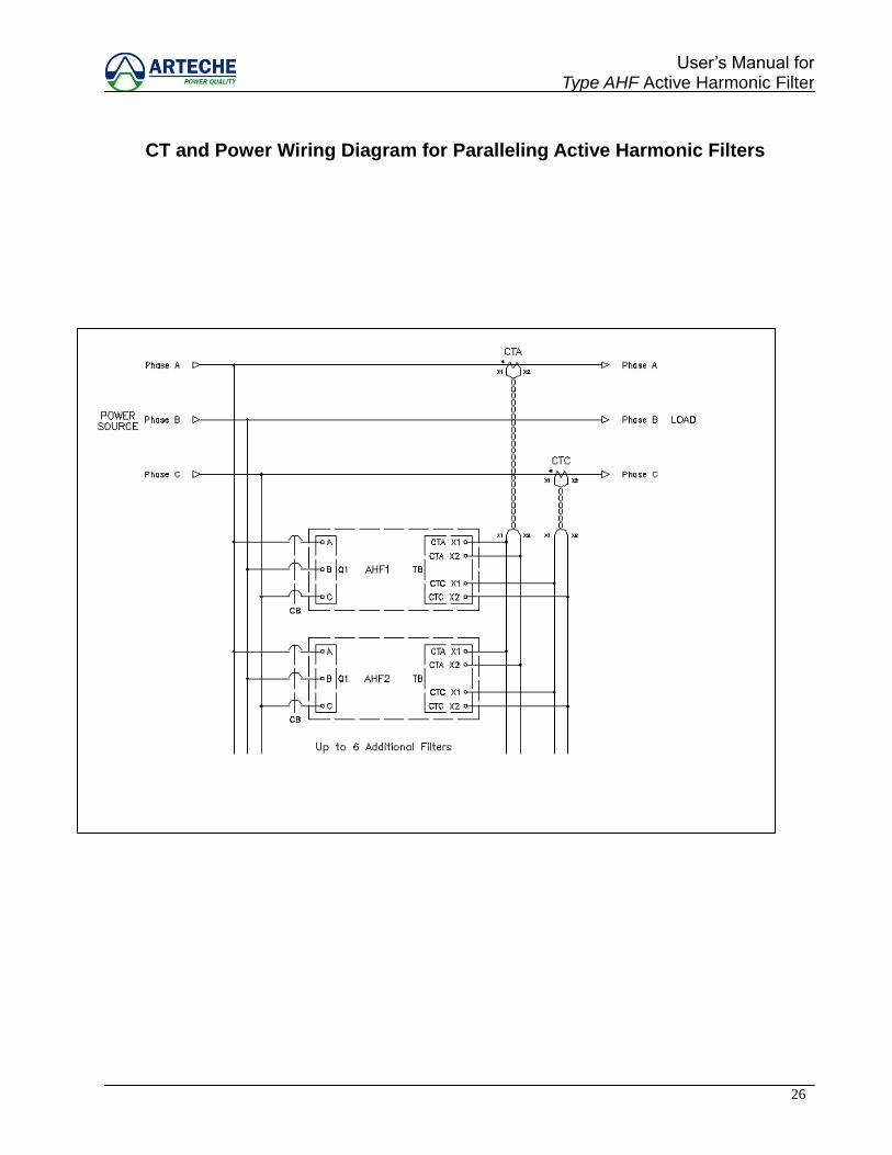
CT and Power Wiring Diagram for Paralleling Active Harmonic Filters

27
User‟s Manual for Type AHF Active Harmonic Filter
CT and Internal Wiring Diagram for Paralleling Active Harmonic Filters
28
User‟s Manual for Type AHF Active Harmonic Filter
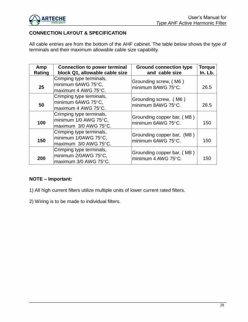
CONNECTION LAYOUT & SPECIFICATION All cable entries are from the bottom of the AHF cabinet. The table below shows the type of terminals and their maximum allowable cable size capability.
Amp
Rating Connection to power terminal block Q1, allowable cable size
Ground connection type and cable size
Torque In. Lb.
25
Crimping type terminals,
minimum 6AWG 75C,
maximum 4 AWG 75C.
Grounding screw, ( M6 )
minimum 8AWG 75C. 26.5
50
Crimping type terminals,
minimum 6AWG 75C,
maximum 4 AWG 75C.
Grounding screw, ( M6 )
minimum 8AWG 75C. 26.5
100
Crimping type terminals,
minimum 1/0 AWG 75C,
maximum 3/0 AWG 75C.
Grounding copper bar, ( M8 )
minimum 6AWG 75C. 150
150
Crimping type terminals,
minimum 1/0AWG 75C,
maximum 3/0 AWG 75C.
Grounding copper bar, (M8 )
minimum 6AWG 75C. 150
200
Crimping type terminals,
minimum 2/0AWG 75C,
maximum 3/0 AWG 75C.
Grounding copper bar, ( M8 )
minimum 4 AWG 75C. 150
NOTE – Important: 1) All high current filters utilize multiple units of lower current rated filters. 2) Wiring is to be made to individual filters.
29
User‟s Manual for Type AHF Active Harmonic Filter
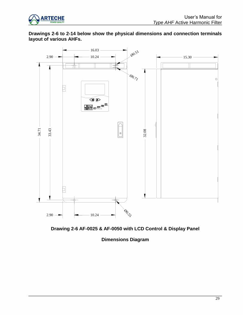
Drawings 2-6 to 2-14 below show the physical dimensions and connection terminals layout of various AHFs.
2.90 10.24
33
.43
32
.08
2.90 10.24
ON/OFF
ESCFILTERING
ERRORCORRECTINGFULL
POWER ON
RESET
34
.71
16.03
15.30
Ø0.71
Ø0.55
Ø0.51
Drawing 2-6 AF-0025 & AF-0050 with LCD Control & Display Panel
Dimensions Diagram

30
User‟s Manual for Type AHF Active Harmonic Filter
A B C
CTA
X2
TB
1 X1 X1 X2 6
CTC
X2X1
X2X1
SECONDARY
CT
INCOMING POWER3O3W
Q1
Q1TB
APJP2
APJT2
APJI2
APJI5
Drawing 2-7 AF-0025 & AF-0050 Wiring Position
Connections Diagram
31
User‟s Manual for Type AHF Active Harmonic Filter
FILTERING
ESC
ERROR
FULLCORRECTING
POWER ON
RESETON/OFF
27.83
31.8823.62
21.65
77.8
7
76.0
0
VENTILATION
GRILL
(AIR INLET)
VENTILATION
GRILL
(AIR INLET)
FRONT VIEW RIGHT SIDE VIEW
HANGERS
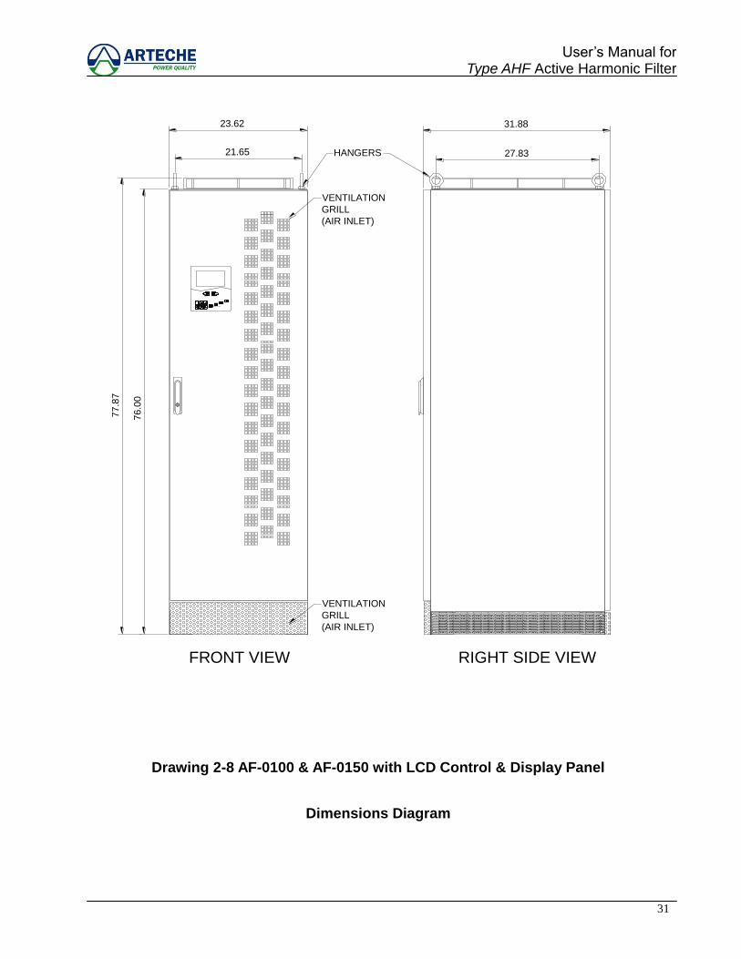
Drawing 2-8 AF-0100 & AF-0150 with LCD Control & Display Panel
Dimensions Diagram
32
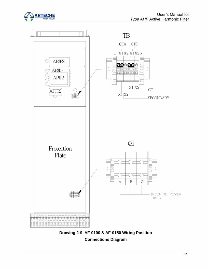
User‟s Manual for Type AHF Active Harmonic Filter
SECONDARYX2X1
X1 X2CT
1 X2X1 X1X26
TB
CTA CTC
ProtectionPlate
APJI2
APJT2
APJP2
APJI5
Q1
A B C
A B C
Drawing 2-9 AF-0100 & AF-0150 Wiring Position
Connections Diagram
33
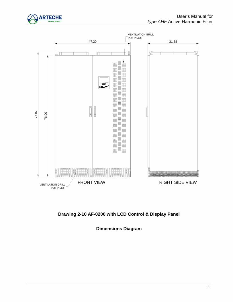
User‟s Manual for Type AHF Active Harmonic Filter
RIGHT SIDE VIEWFRONT VIEWVENTILATION GRILL
(AIR INLET)
ESC POWER ON
CORRECTINGERROR
FULL
FILTERING
RESET
VENTILATION GRILL
(AIR INLET)
ON/OFF
31.8847.20
77.8
7
76.0
0
Drawing 2-10 AF-0200 with LCD Control & Display Panel
Dimensions Diagram
34
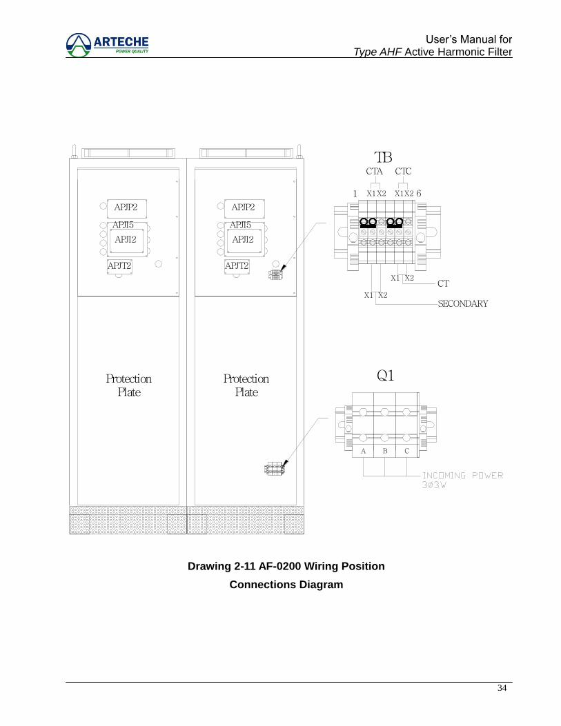
User‟s Manual for Type AHF Active Harmonic Filter
1 X1X2 6X1X2
TBCTA CTC
APJI2
APJT2
APJP2
APJI5
APJI2
APJT2
APJP2
APJI5
Q1
A B C
A B C
CT
SECONDARYX1 X2
X1 X2
ProtectionPlate
ProtectionPlate
Drawing 2-11 AF-0200 Wiring Position
Connections Diagram
35
User‟s Manual for Type AHF Active Harmonic Filter
OPERATION
CONTROL PANEL
Summary
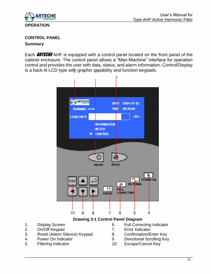
Each ARTECHE AHF is equipped with a control panel located on the front panel of the cabinet enclosure. The control panel allows a “Man-Machine” interface for operation control and provides the user with data, status, and alarm information. Control/Display is a back-lit LCD type with graphic capability and function keypads.
Drawing 3-1 Control Panel Diagram
1. Display Screen 6. Full Correcting Indicator 2. On/Off Keypad 7. Error Indicator 3. Reset (Alarm Silence) Keypad 8. Confirmation/Enter Key 4. Power On Indicator 9. Directional Scrolling Key 5. Filtering Indicator 10. Escape/Cancel Key
5 4 6 7
1 2
3
8 9 10
36
User‟s Manual for Type AHF Active Harmonic Filter
FUNCTIONAL DESCRIPTIONS
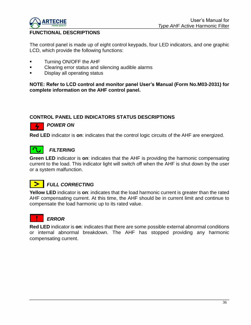
The control panel is made up of eight control keypads, four LED indicators, and one graphic LCD, which provide the following functions: Turning ON/OFF the AHF Clearing error status and silencing audible alarms Display all operating status NOTE: Refer to LCD control and monitor panel User’s Manual (Form No.M03-2031) for complete information on the AHF control panel.
CONTROL PANEL LED INDICATORS STATUS DESCRIPTIONS
Red LED indicator is on: indicates that the control logic circuits of the AHF are energized.
Green LED indicator is on: indicates that the AHF is providing the harmonic compensating current to the load. This indicator light will switch off when the AHF is shut down by the user or a system malfunction.
Yellow LED indicator is on: indicates that the load harmonic current is greater than the rated AHF compensating current. At this time, the AHF should be in current limit and continue to compensate the load harmonic up to its rated value.
Red LED indicator is on: indicates that there are some possible external abnormal conditions or internal abnormal breakdown. The AHF has stopped providing any harmonic
compensating current.
POWER ON
FILTERING
FULL CORRECTING
ERROR
37
User‟s Manual for Type AHF Active Harmonic Filter
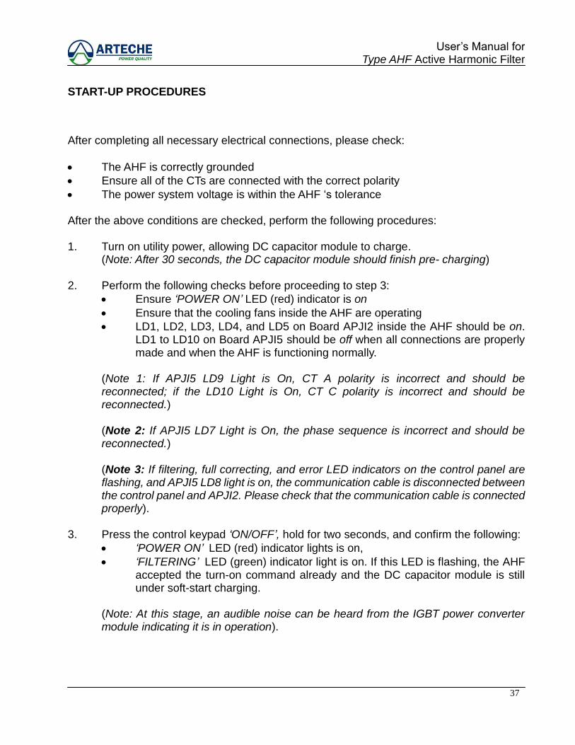
START-UP PROCEDURES
After completing all necessary electrical connections, please check:
The AHF is correctly grounded
Ensure all of the CTs are connected with the correct polarity
The power system voltage is within the AHF „s tolerance After the above conditions are checked, perform the following procedures: 1. Turn on utility power, allowing DC capacitor module to charge. (Note: After 30 seconds, the DC capacitor module should finish pre- charging) 2. Perform the following checks before proceeding to step 3:
Ensure ‘POWER ON’ LED (red) indicator is on
Ensure that the cooling fans inside the AHF are operating
LD1, LD2, LD3, LD4, and LD5 on Board APJI2 inside the AHF should be on. LD1 to LD10 on Board APJI5 should be off when all connections are properly made and when the AHF is functioning normally.
(Note 1: If APJI5 LD9 Light is On, CT A polarity is incorrect and should be reconnected; if the LD10 Light is On, CT C polarity is incorrect and should be reconnected.) (Note 2: If APJI5 LD7 Light is On, the phase sequence is incorrect and should be reconnected.) (Note 3: If filtering, full correcting, and error LED indicators on the control panel are flashing, and APJI5 LD8 light is on, the communication cable is disconnected between the control panel and APJI2. Please check that the communication cable is connected properly).
3. Press the control keypad ‘ON/OFF’, hold for two seconds, and confirm the following:
‘POWER ON’ LED (red) indicator lights is on,
‘FILTERING’ LED (green) indicator light is on. If this LED is flashing, the AHF accepted the turn-on command already and the DC capacitor module is still under soft-start charging.
(Note: At this stage, an audible noise can be heard from the IGBT power converter module indicating it is in operation).
38
User‟s Manual for Type AHF Active Harmonic Filter
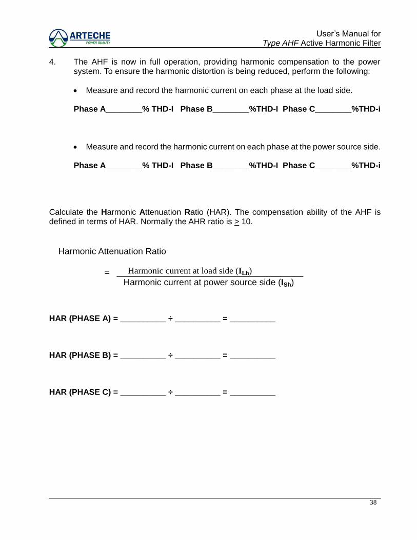
4. The AHF is now in full operation, providing harmonic compensation to the power system. To ensure the harmonic distortion is being reduced, perform the following:
Measure and record the harmonic current on each phase at the load side.
Phase A________% THD-I Phase B________%THD-I Phase C________%THD-i
Measure and record the harmonic current on each phase at the power source side.
Phase A________% THD-I Phase B________%THD-I Phase C________%THD-i
Calculate the Harmonic Attenuation Ratio (HAR). The compensation ability of the AHF is defined in terms of HAR. Normally the AHR ratio is > 10.
HAR (PHASE A) = __________ ÷ __________ = __________
HAR (PHASE B) = __________ ÷ __________ = __________
HAR (PHASE C) = __________ ÷ __________ = __________
Harmonic current at load side (ILh)
Harmonic current at power source side (ISh) = _________________________________________
Harmonic Attenuation Ratio

39
User‟s Manual for Type AHF Active Harmonic Filter
SHUTDOWN PROCEDURES
CAUTION!
Shutting down the AHF should only be carried out during repair or major maintenance of the entire power system or AHF to ensure minimum disruption to critical operations connected to the power system.
The following shutdown procedures should be performed only by authorized personnel: 1. Press the control keypad „ON/OFF‟ for one second, only „POWER ON‟ LED (red)
indicator should remain on. 2. Turn off utility power to complete the shutdown procedures.
Before performing the actual repair to the AHF, wait at least for three minutes to ensure any residual current and voltage has been completely discharged from the DC Capacitors Module.
SILENCING THE ALARM
The AHF control panel provides both audible and visual alarms during abnormal system conditions or AHF malfunctions. The alarm buzzer can be silenced by pressing the control keypad „RESET‟ for two seconds. The „ERROR‟ indicator (red) LED remains on until the fault is cleared.
DANGER
!
40
User‟s Manual for Type AHF Active Harmonic Filter
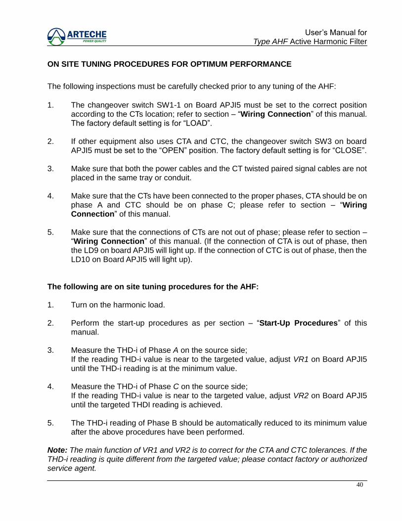
ON SITE TUNING PROCEDURES FOR OPTIMUM PERFORMANCE
The following inspections must be carefully checked prior to any tuning of the AHF:
1. The changeover switch SW1-1 on Board APJI5 must be set to the correct position
according to the CTs location; refer to section – “Wiring Connection” of this manual. The factory default setting is for “LOAD”.
2. If other equipment also uses CTA and CTC, the changeover switch SW3 on board
APJI5 must be set to the “OPEN” position. The factory default setting is for “CLOSE”. 3. Make sure that both the power cables and the CT twisted paired signal cables are not
placed in the same tray or conduit. 4. Make sure that the CTs have been connected to the proper phases, CTA should be on
phase A and CTC should be on phase C; please refer to section – “Wiring Connection” of this manual.
5. Make sure that the connections of CTs are not out of phase; please refer to section –
“Wiring Connection” of this manual. (If the connection of CTA is out of phase, then the LD9 on board APJI5 will light up. If the connection of CTC is out of phase, then the LD10 on Board APJI5 will light up).
The following are on site tuning procedures for the AHF: 1. Turn on the harmonic load. 2. Perform the start-up procedures as per section – “Start-Up Procedures” of this
manual. 3. Measure the THD-i of Phase A on the source side; If the reading THD-i value is near to the targeted value, adjust VR1 on Board APJI5
until the THD-i reading is at the minimum value. 4. Measure the THD-i of Phase C on the source side; If the reading THD-i value is near to the targeted value, adjust VR2 on Board APJI5
until the targeted THDI reading is achieved. 5. The THD-i reading of Phase B should be automatically reduced to its minimum value
after the above procedures have been performed. Note: The main function of VR1 and VR2 is to correct for the CTA and CTC tolerances. If the THD-i reading is quite different from the targeted value; please contact factory or authorized service agent.
41
User‟s Manual for Type AHF Active Harmonic Filter
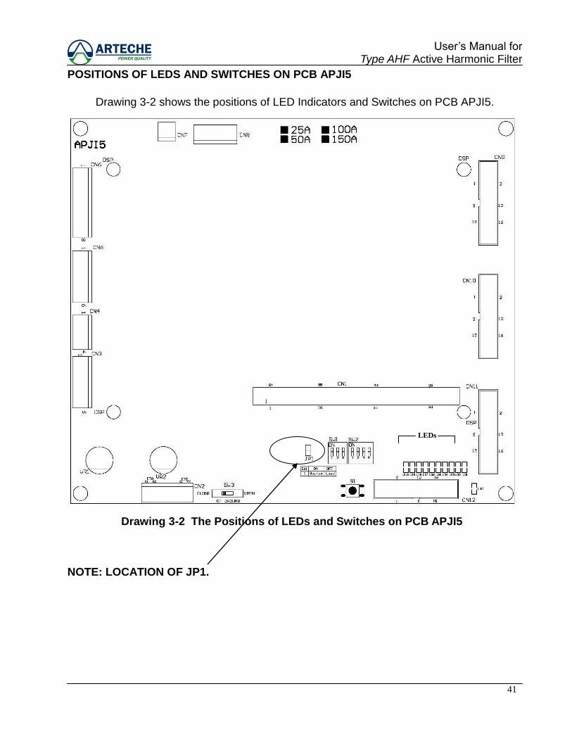
POSITIONS OF LEDS AND SWITCHES ON PCB APJI5
Drawing 3-2 shows the positions of LED Indicators and Switches on PCB APJI5.
Drawing 3-2 The Positions of LEDs and Switches on PCB APJI5
NOTE: LOCATION OF JP1.
LEDs
42
User‟s Manual for Type AHF Active Harmonic Filter
FUNCTION SETTINGS
This section describes the AHF setting functions, including the AHF current ratings, CT locations, harmonic compensation configurations, and smart save energy mode. The parameters setting and configuration are set with SW1 & SW2 on Board APJI5. The AHF can effectively compensate harmonics, from the 3rd to 51st order. The compensated settings are divided into three catagories as followings; 1. Individual Selective Compensation: The 3, 5, 7, 11, 13, 17, 19, 23, and 25
harmonics can be selected individually. A maximum of four orders can be enabled simultaneously.
2. Higher-order Group Compensation: Compensate simultaneously higher-order
harmonics from the 15 to 51 components. 3. Reactive Compensation Mode: Disable harmonic compensation and only provide
reactive power. The harmonic compensation mode setting descriptions are shown on the chart 3-3 of this manual.
SMART SAVE ENERGY MODE The Smart Energy Saving mode provides the function of automatic start-up and shutdown, according to load current level. When load harmonic current is less than minimum-off current level, the AHF will shutdown automatically until the load harmonic current is greater than maximum-on current level. This feature is used to save energy by turning OFF filtering whenever the load harmonic current is less than 5% of the AHF unit rated current. It turns back ON when the load harmonic current increases to greater than 10% of the filter rated current (factory settings). In this mode, the AHF will also turn OFF the fixed KVAR provided by the filter, which also reduces the chances of having leading power factor. Refer below to chart 3-3 of this manual.

43
User‟s Manual for Type AHF Active Harmonic Filter
CONFIGURE HARMONIC SELECTION
The following are configuration procedures for harmonic selection compensation for the AHF: 1. Press the control keypad „ON/OFF‟ for one second to shutdown the AHF, only the
„POWER ON‟ LED (red) indicator should remain on. 2. Use a short piece of jumper wire (not included) to connect both terminals of JP1 on
board APJI5 together. 3. Press button S2 on board APJI2 for one second to reset the controller of the AHF. 4. Check the five LEDs from LD1 to LD5, on board APJI5. Each of these LEDs should be
illuminated, indicating the AHF controller is ready for the configuration mode. 5. Remove the jumper wire from JP1 on board APJI5. 6. Determine the AHF current rating, and then refer to the chart 3-2 and set SW1 on
board APJI5.
Chart 3-2 SW1 Setting
Rated
Current
CT
Location
25A
50A
100A
150A
200A
Load ON
1 2 3
ON
1 2 3
Source ON
1 2 3
ON
1 2 3 : ON : OFF
7. Refer to the chart 3-3 (next page of this manual), and then set SW2 on board APJI5 to
select the desired harmonics compensation. 8. Press button B1 on Board APJI5 until the 5 LEDs, from LD5 to LD1, on Board APJI5
turn off sequentially. This indicates the new configuration parameters are effective. 9. Operate the control panel to turn on the AHF.
44
User‟s Manual for Type AHF Active Harmonic Filter
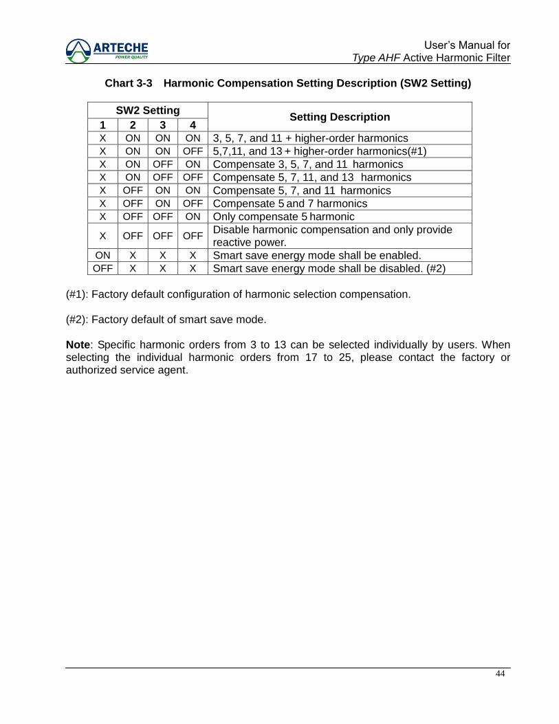
Chart 3-3 Harmonic Compensation Setting Description (SW2 Setting)
SW2 Setting Setting Description
1 2 3 4 X ON ON ON 3, 5, 7, and 11 + higher-order harmonics X ON ON OFF 5,7,11, and 13 + higher-order harmonics(#1) X ON OFF ON Compensate 3, 5, 7, and 11 harmonics X ON OFF OFF Compensate 5, 7, 11, and 13 harmonics X OFF ON ON Compensate 5, 7, and 11 harmonics X OFF ON OFF Compensate 5 and 7 harmonics X OFF OFF ON Only compensate 5 harmonic
X OFF OFF OFF Disable harmonic compensation and only provide reactive power.
ON X X X Smart save energy mode shall be enabled. OFF X X X Smart save energy mode shall be disabled. (#2)
(#1): Factory default configuration of harmonic selection compensation. (#2): Factory default of smart save mode. Note: Specific harmonic orders from 3 to 13 can be selected individually by users. When selecting the individual harmonic orders from 17 to 25, please contact the factory or authorized service agent.
45
User‟s Manual for Type AHF Active Harmonic Filter
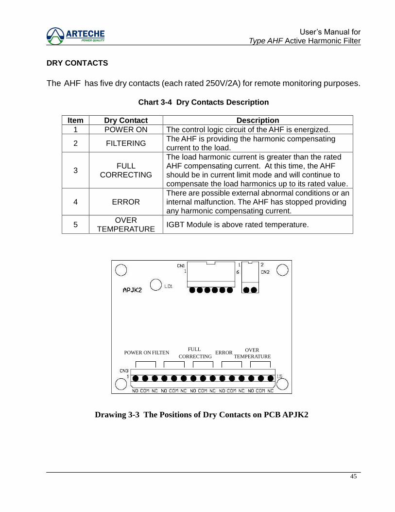
DRY CONTACTS
The AHF has five dry contacts (each rated 250V/2A) for remote monitoring purposes.
Chart 3-4 Dry Contacts Description
Item Dry Contact Description
1 POWER ON The control logic circuit of the AHF is energized.
2 FILTERING The AHF is providing the harmonic compensating current to the load.
3 FULL
CORRECTING
The load harmonic current is greater than the rated AHF compensating current. At this time, the AHF should be in current limit mode and will continue to compensate the load harmonics up to its rated value.
4 ERROR There are possible external abnormal conditions or an internal malfunction. The AHF has stopped providing any harmonic compensating current.
5 OVER
TEMPERATURE IGBT Module is above rated temperature.
Drawing 3-3 The Positions of Dry Contacts on PCB APJK2
POWER ON FILTEN CORRECTING
ERROR OVER FULL
TEMPERATURE
46
User‟s Manual for Type AHF Active Harmonic Filter
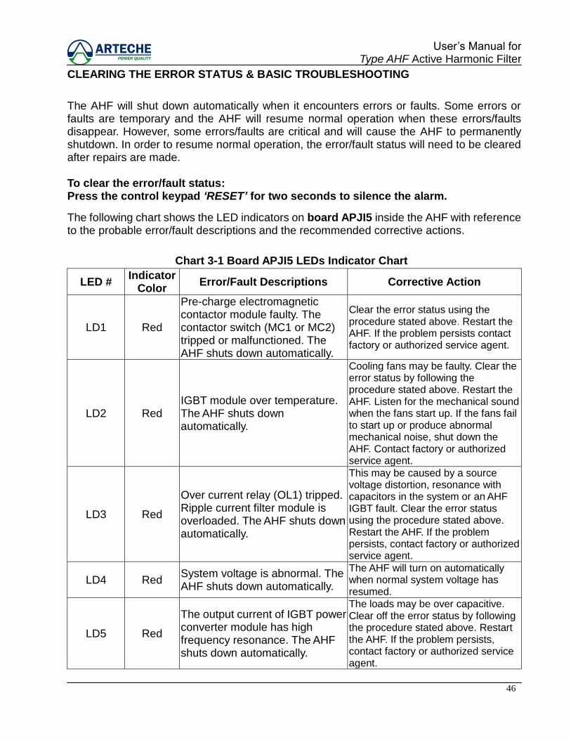
CLEARING THE ERROR STATUS & BASIC TROUBLESHOOTING
The AHF will shut down automatically when it encounters errors or faults. Some errors or faults are temporary and the AHF will resume normal operation when these errors/faults disappear. However, some errors/faults are critical and will cause the AHF to permanently shutdown. In order to resume normal operation, the error/fault status will need to be cleared after repairs are made. To clear the error/fault status: Press the control keypad „RESET‟ for two seconds to silence the alarm.
The following chart shows the LED indicators on board APJI5 inside the AHF with reference to the probable error/fault descriptions and the recommended corrective actions.
Chart 3-1 Board APJI5 LEDs Indicator Chart
LED # Indicator
Color Error/Fault Descriptions Corrective Action
LD1 Red
Pre-charge electromagnetic contactor module faulty. The contactor switch (MC1 or MC2) tripped or malfunctioned. The AHF shuts down automatically.
Clear the error status using the procedure stated above. Restart the AHF. If the problem persists contact factory or authorized service agent.
LD2 Red IGBT module over temperature. The AHF shuts down automatically.
Cooling fans may be faulty. Clear the error status by following the procedure stated above. Restart the AHF. Listen for the mechanical sound when the fans start up. If the fans fail to start up or produce abnormal mechanical noise, shut down the AHF. Contact factory or authorized service agent.
LD3 Red
Over current relay (OL1) tripped. Ripple current filter module is overloaded. The AHF shuts down automatically.
This may be caused by a source voltage distortion, resonance with capacitors in the system or an AHF IGBT fault. Clear the error status using the procedure stated above. Restart the AHF. If the problem persists, contact factory or authorized service agent.
LD4 Red System voltage is abnormal. The AHF shuts down automatically.
The AHF will turn on automatically when normal system voltage has resumed.
LD5 Red
The output current of IGBT power converter module has high frequency resonance. The AHF shuts down automatically.
The loads may be over capacitive. Clear off the error status by following the procedure stated above. Restart the AHF. If the problem persists, contact factory or authorized service agent.
47
User‟s Manual for Type AHF Active Harmonic Filter
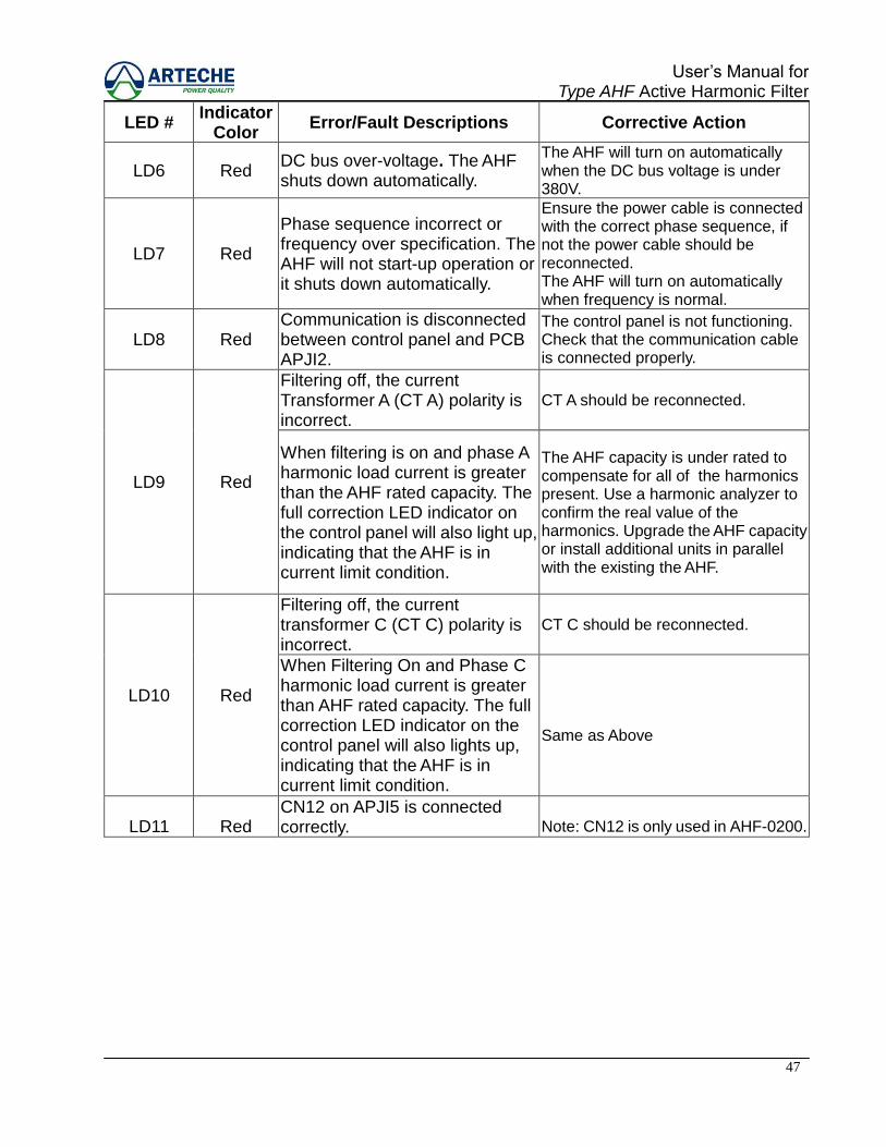
LED #
Indicator Color
Error/Fault Descriptions Corrective Action
LD6 Red DC bus over-voltage. The AHF shuts down automatically.
The AHF will turn on automatically when the DC bus voltage is under 380V.
LD7 Red
Phase sequence incorrect or frequency over specification. The AHF will not start-up operation or it shuts down automatically.
Ensure the power cable is connected with the correct phase sequence, if not the power cable should be reconnected. The AHF will turn on automatically when frequency is normal.
LD8 Red Communication is disconnected between control panel and PCB APJI2.
The control panel is not functioning. Check that the communication cable is connected properly.
LD9 Red
Filtering off, the current Transformer A (CT A) polarity is incorrect.
CT A should be reconnected.
When filtering is on and phase A harmonic load current is greater than the AHF rated capacity. The full correction LED indicator on the control panel will also light up, indicating that the AHF is in current limit condition.
The AHF capacity is under rated to compensate for all of the harmonics present. Use a harmonic analyzer to confirm the real value of the harmonics. Upgrade the AHF capacity or install additional units in parallel with the existing the AHF.
LD10 Red
Filtering off, the current transformer C (CT C) polarity is incorrect.
CT C should be reconnected.
When Filtering On and Phase C harmonic load current is greater than AHF rated capacity. The full correction LED indicator on the control panel will also lights up, indicating that the AHF is in current limit condition.
Same as Above
LD11 Red CN12 on APJI5 is connected correctly. Note: CN12 is only used in AHF-0200.
48
User‟s Manual for Type AHF Active Harmonic Filter
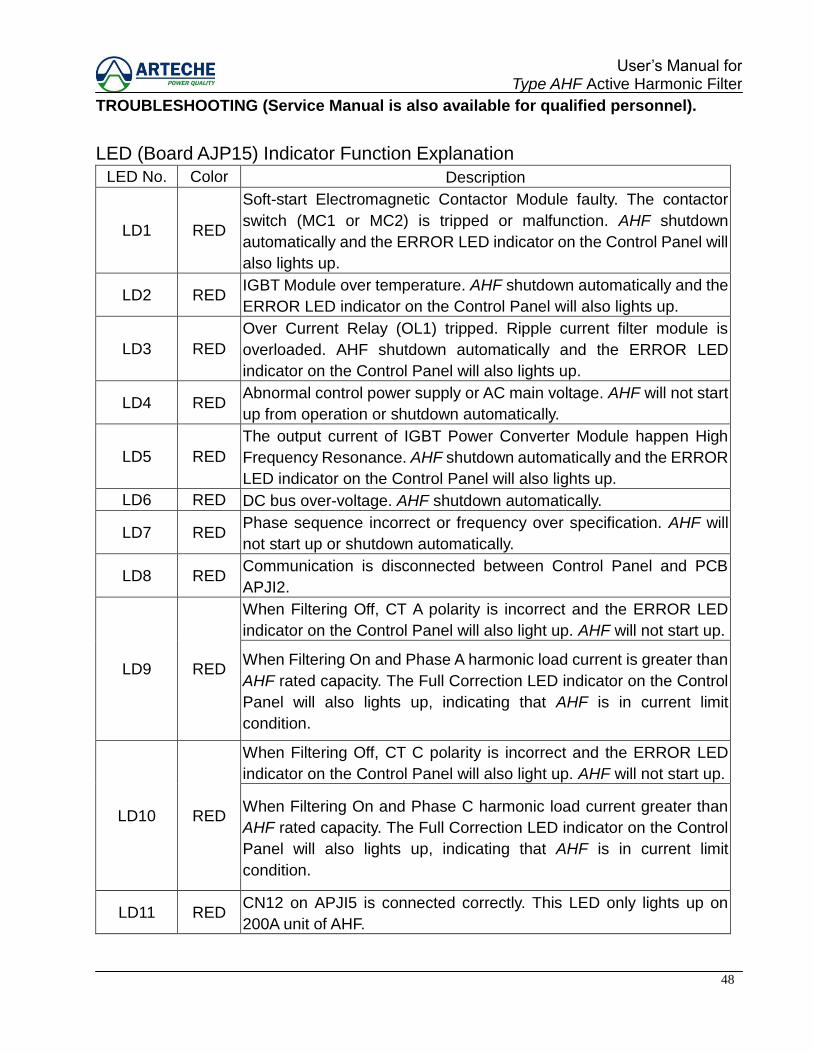
TROUBLESHOOTING (Service Manual is also available for qualified personnel).
LED (Board AJP15) Indicator Function Explanation
LED No. Color Description
LD1 RED
Soft-start Electromagnetic Contactor Module faulty. The contactor
switch (MC1 or MC2) is tripped or malfunction. AHF shutdown
automatically and the ERROR LED indicator on the Control Panel will
also lights up.
LD2 RED IGBT Module over temperature. AHF shutdown automatically and the
ERROR LED indicator on the Control Panel will also lights up.
LD3 RED
Over Current Relay (OL1) tripped. Ripple current filter module is
overloaded. AHF shutdown automatically and the ERROR LED
indicator on the Control Panel will also lights up.
LD4 RED Abnormal control power supply or AC main voltage. AHF will not start
up from operation or shutdown automatically.
LD5 RED
The output current of IGBT Power Converter Module happen High
Frequency Resonance. AHF shutdown automatically and the ERROR
LED indicator on the Control Panel will also lights up.
LD6 RED DC bus over-voltage. AHF shutdown automatically.
LD7 RED Phase sequence incorrect or frequency over specification. AHF will
not start up or shutdown automatically.
LD8 RED Communication is disconnected between Control Panel and PCB
APJI2.
LD9 RED
When Filtering Off, CT A polarity is incorrect and the ERROR LED
indicator on the Control Panel will also light up. AHF will not start up.
When Filtering On and Phase A harmonic load current is greater than
AHF rated capacity. The Full Correction LED indicator on the Control
Panel will also lights up, indicating that AHF is in current limit
condition.
LD10 RED
When Filtering Off, CT C polarity is incorrect and the ERROR LED
indicator on the Control Panel will also light up. AHF will not start up.
When Filtering On and Phase C harmonic load current greater than
AHF rated capacity. The Full Correction LED indicator on the Control
Panel will also lights up, indicating that AHF is in current limit
condition.
LD11 RED CN12 on APJI5 is connected correctly. This LED only lights up on
200A unit of AHF.

49
User‟s Manual for Type AHF Active Harmonic Filter
BASIC INSTALLATION AND MAINTENANCE
Correct installation is required for proper performance and function of the active filter.
Physical inspection of equipment for damage is recommended, prior to any installation.
Indoor storage is recommended for indoor rated equipment and should be in a clean, dry
environment. Outdoor storage of outdoor rated equipment may require installation of
additional materials shipped for site assembly. Where recommended, packaging materials
may be required to be removed.
Equipment includes lifting lugs, for transport and site installation handling. As a cautionary
note, placement of the AHF is to be at a level and solid location, for correct operation.
National Electrical Code (NEC), is to be observed during the installation. Electrical
connections are also to be in compliance with required codes
It is recommended that the installer inspect and verify proper alignment, anchorage and
grounding, proper connections and tightness of connections, prior to any start-up functions.
Generally, AHF‟s are considered to be maintenance free devices. The following
Inspections should be made during regular maintenance intervals:
Remove any excess dust or dirt that may have accumulated within cabinet.
Perform visual exterior and interior inspection
Note any lights/alarms and take corrective action
Check display to assure AHF is providing correct harmonic cancellation

50
User‟s Manual for Type AHF Active Harmonic Filter
Technical support is available by contacting the factory:
Telephone 1-262-754-3883
Fax 1-262-754-3993
Email [email protected]
Website www.artechepq.com
ARTECHE PQ, INC.
16964 West Victor Road
New Berlin, WI 53151
Related Documents