Type 2A Models Type 2A Models Type 2A Models Form# 42859-01 20110415 ©2011 Hunter Fan Co. For Your Records and Warranty Assistance For reference, also attach your receipt or a copy of your receipt to the manual. __________________________________________ Model Name __________________________________________ Model No. __________________________________________ Date Purchased __________________________________________ Where Purchased English Español Owner’s Guide and Installation Manual

Welcome message from author
This document is posted to help you gain knowledge. Please leave a comment to let me know what you think about it! Share it to your friends and learn new things together.
Transcript

Type 2A ModelsType 2A ModelsType 2A Models
Form# 42859-0120110415©2011 Hunter Fan Co.
For Your Records andWarranty AssistanceFor reference, also attach your receipt or a copyof your receipt to the manual.
__________________________________________Model Name
__________________________________________Model No.
__________________________________________Date Purchased
__________________________________________Where Purchased
EnglishEspañol
Owner’s Guide and Installation Manual

2
42859-01 • 04/15/11 • Hunter Fan Company
Table Of Contents
Preparing the Fan Site . . . . . . . . . . . . . . . . . 3
1 • Getting Ready . . . . . . . . . . . . . . . . . . . . . . 6
2 • Installing the Hanger Bracket . . . . . . . 7
3 • Assembling and Hanging the Fan . . . 8
4 •Wiring the Fan . . . . . . . . . . . . . . . . . . . . . . 9
5 • Installing the Motor Housing . . . . . . . 10
6 • Assembling the Blades . . . . . . . . . . . . . . 11
8 • Operating and Cleaning Your Ceiling Fan . . . . . . . . . . . . . . . . . . . . . . . . . . . . . . . 16
9 • Troubleshooting . . . . . . . . . . . . . . . . . . . . 17
© 2011 Hunter Fan Company
Welcome
Your new Hunter® ceiling fan is an addition to your home or office that will provide comfort and performance for many years. This installation and operation manual gives you complete instructions for installing and operating your fan.
We are proud of our work. We appreciate the opportunity to supply you with the best ceiling fan available anywhere in the world.
Before installing your fan, for your records and warranty assistance, record information from the carton and Hunter nameplate label (located on the top of the fan motor housing).
Cautions and Warnings• READ THIS ENTIRE MANUAL CAREFULLY BEFORE BEGINNING
INSTALLATION. SAVE THESE INSTRUCTIONS.• Use only Hunter replacement parts.• To reduce the risk of personal injury, attach the fan directly to the
support structure of the building according to these instructions, and use only the hardware supplied.
• To avoid possible electrical shock, before installing your fan, disconnect the power by turning off the circuit breakers to the outlet box and associated wall switch location. If you cannot lock the circuit breakers in the off position, securely fasten a prominent warning device, such as a tag, to the service panel.
• All wiring must be in accordance with national and local electrical codes and ANSI/NFPA 70. If you are unfamiliar with wiring, use a qualified electrician.
• To reduce the risk of personal injury, do not bend the blade attachment system when installing, balancing, or cleaning the fan. Never insert foreign objects between rotating fan blades.
• To reduce the risk of fire, electrical shock, or motor damage, do not use a solid-state speed control with this fan. Use only Hunter speed controls.
• This product conforms to UL STD 507 and is certified to STD C22.2 No.113• Wash your hands after your fan installation is complete.

3
42859-01 • 04/15/11 • Hunter Fan Company
7’ Minimum Blades to Floor
8’ Minimum Ceiling Height
30” From Wall or Nearest Obstruction
Step 1 - Choose the Fan SiteProper ceiling fan location and attachment to the building structure are essential for safety, reliable operation, maximum efficiency, and energy savings.
Choose a fan site where:• No object can come in contact with the rotating fan blades during
normal operation.
• The fan blades are at least 7 feet above the floor and the ceiling is at least 8 feet high.
• The fan blades have no obstructions to airflow, such as walls or posts, within 30 inches of the fan blade tips.
• The fan is directly below a joist or support brace that will hold the outlet box and the full weight of the fan.
Checklist for Existing Fan SiteIf you want to use an existing fan site, complete the following checklist to determine if the site is acceptable and safe for your new Hunter fan. If you cannot check off every item, prepare a new fan site as described on this page.Fan Support System• Fan attaches directly to building structure.• Fan support system will hold full weight of the fan and light kit.Ceiling Hole• The outlet box clearance hole is directly below the joist or support brace.Outlet Box• The outlet box is an UL-approved octagonal 4” x 1-1/2” outlet box (or as
specified by the support brace manufacturer).• The outlet box is secured to the joist or support brace by wood screws
and washers through the inner holes of outlet box.• The outer holes of the outlet box are aligned with joist or support brace.• The bottom of the outlet box is recessed a minimum of 1/16” into
ceiling.Wiring• The electrical cable is secured to outlet box by an approved connector.• Six inches of lead wires extend from outlet box.If your existing fan site is suitable, skip ahead to Section 2 • Installing the Ceiling Plate.
Suitable Existing Fan SiteFan Support System
Fan Support System
Wiring
Outlet Box
Preparing the Fan Site

4
42859-01 • 04/15/11 • Hunter Fan Company
Preparing the Fan Site (continued)
CAUTION: All wiring must be in accordance with national and local electrical codes and ANSI/NFPA 70. If you are unfamiliar with wiring, use a qualified electrician.
Steps 2 – 3
Step 4
Step 5
Step 2 - Cut the Ceiling Hole2-1. Locate the site for the ceiling hole directly below the joist or support brace that
will hold the outlet box and fan.2-2. Cut a 4” diameter hole through the drywall or plaster of the ceiling. You will use
the hole to install the support brace and outlet box.
Step 3 - Install a Support Brace, If NecessaryDetermine if there is a ceiling joist directly above the ceiling hole. If the joist is there, determine if it is positioned to allow you to recess the outlet box a minimum of 1/16” into the ceiling. If NOT, install a support brace as follows:3-1. Attach a 2” x 4” support brace between two joists. Position it to allow you to
recess the bottom of the outlet box a minimum of 1/16” into the ceiling.3-2. Check the support brace to ensure it will support the full weight of the fan and
light kit.
Step 4 - Install the Outlet Box4-1. Obtain a UL-approved octagonal 4” x 1-1/2” outlet box, plus two #8 x 1-1/2”
wood screws and washers, available from any hardware store or electrical supply house.
4-2. Orient the outlet box so that both the inner and outer holes in the box align with the joist or support brace.
4-3. Drill pilot holes no larger than the minor diameter of the wood screws (5/64”) through the inner holes of the outlet box.
4-4. Attach the outlet box directly to the support brace or joist with two #8 x 1-1/2” wood screws and washers. The bottom of the outlet box must be recessed a minimum of 1/16” into the ceiling.
Step 5 - Prepare the Wiring5-1. Make sure the circuit breakers to the fan supply line leads and associated wall
switch location are turned off . If you cannot lock the circuit breakers in the off position, securely fasten a prominent warning device, such as a tag, to the service panel.
5-2. Thread the fan supply line through the outlet box so that the fan supply line extends at least 6” beyond the box.
5-3. Attach the fan supply line to the outlet box with an approved connector, available at any hardware store or electrical supply house.
5-4. Make certain the wiring meets all national and local standards and ANSI/NFPA 70 .
You have now successfully prepared your ceiling fan site. For instructions to install your ceiling fan, go to your fan manual and continue with Section 2 • Installing the Ceiling Plate.

5
42859-01 • 04/15/11 • Hunter Fan Company
Mounting and Optional Accessories
Understanding MountingHunter’s patented mounting system provides you maximum ease in installing your fan. This fan was designed to be mounted only on flat ceilings and can be used on ceilings less than 8 feet high.
Considering Optional AccessoriesConsider using Hunter’s optional accessories, including a wall-mounted or remote speed control. To install and use the accessories, follow the instructions included with each product. For quiet and optimum performance of your Hunter fan, use only Hunter speed controls.
Low Profile Mounting fits close to the ceiling, recommended for ceilings less than 8 feet high
Support Brace
Low Profile Mounting Style
Ceiling Outlet Box
CAUTION: To reduce the risk of personal injury, attach the fan directly to the support structure of the building according to these instructions, and use only the hardware supplied.

6
42859-01 • 04/15/11 • Hunter Fan Company
To install a ceiling fan, be sure you can do the following:
• Locate the ceiling joist or other suitable support in ceiling.
• Drill holes for and install wood screws.
• Identify and connect electrical wires.
• Lift 40 pounds.
If you need help installing the fan, your Hunter fan dealer can direct you to a licensed installer or electrician.
Gathering the ToolsYou will need the following tools for installing the fan:
• Electric drill with 9/64” bit
• Standard screwdriver (magnetic tip recommended)
• Phillips-head screwdriver (magnetic tip recommended)
• Wrench or pliers
• Ladder (height dependent upon installation site)
Checking Your Fan PartsCarefully unpack your fan to avoid damage to the fan parts. Refer to the included Parts Guide. Check for any shipping damage to the motor or fan blades. If any parts are missing or damaged, contact your Hunter dealer or call Hunter Technical Support Department at 888-830-1326 (In Canada, call 1-866-268-1936).
Installing Multiple Fans?If you are installing more than one fan, keep the fan blades and blade irons (if applicable) in sets, as they were shipped.
1 • Getting Ready

7
42859-01 • 04/15/11 • Hunter Fan Company
CAUTION: To avoid possible electrical shock, before installing your fan, disconnect the power by turning off the circuit breakers to the outlet box and associated wall switch location. If you cannot lock the circuit breakers in the off position, securely fasten a prominent warning device, such as a tag, to the service panel.
2-1. Drill two pilot holes into the wood support structure through the outermost holes in the outlet box. The pilot holes should be 9/64” in diameter.
2-2. Partially install two canopy screws in the holes on each end of the hanger bracket, as shown in the figure to the right.
2-3. Your fan comes with four mounting isolators. Position the isolators between the hanger bracket and ceiling by inserting the raised areas on each isolator into the holes in the hanger bracket.
2-4. Thread the lead wires from the outlet box down through the hole in the middle of the hanger bracket.
2-5. Align the slotted holes in the hanger bracket with the pilot holes you drilled in the wood support structure.
Note: The isolators should be flush against the ceiling.
2-6. Place a flat washer on each of the two 3” wood screws and pass the screws through the slotted holes in the hanger bracket into the pilot holes you drilled.
Tighten the screws into the 9/64” pilot holes; do not use lubricants on the screws. Do not over tighten.
Step 2-2
Flat Washer
3” Wood Screw
Steps 2-4 – 2-6
Hanger Bracket
Step 2-3
Canopy Screw
Canopy Screw
Isolator
2 • Installing the Hanger Bracket

8
42859-01 • 04/15/11 • Hunter Fan Company
Step 3-2
#8-32 x 1” Screw
Green Ground Wire
3-1. Position the square hanger so that the green ground wire attached to the square faces out of the large opening in the metal bracket.
3-2. Holding the wires out of the way, lift the motor assembly and place the square hanger into the opening in the ceiling plate.
WARNING: Make sure the square hanger can not rotate in the metal bracket. Failure to do so could result in the fan falling.
3-3. Install two locking screws through the holes in the side of the metal bracket to secure the square hanger.
Step 3-1
Motor Assembly
Square Hanger
Step 3-3
Locking Screw
Green Ground Wire
3 • Assembling and Hanging the Fan
9
42859-01 • 04/15/11 • Hunter Fan Company
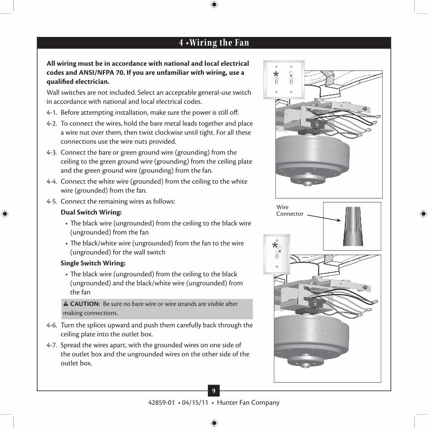
All wiring must be in accordance with national and local electrical codes and ANSI/NFPA 70. If you are unfamiliar with wiring, use a qualified electrician.Wall switches are not included. Select an acceptable general-use switch in accordance with national and local electrical codes.
4-1. Before attempting installation, make sure the power is still off.
4-2. To connect the wires, hold the bare metal leads together and place a wire nut over them, then twist clockwise until tight. For all these connections use the wire nuts provided.
4-3. Connect the bare or green ground wire (grounding) from the ceiling to the green ground wire (grounding) from the ceiling plate and the green ground wire (grounding) from the fan.
4-4. Connect the white wire (grounded) from the ceiling to the white wire (grounded) from the fan.
4-5. Connect the remaining wires as follows:
Dual Switch Wiring: • The black wire (ungrounded) from the ceiling to the black wire
(ungrounded) from the fan
• The black/white wire (ungrounded) from the fan to the wire (ungrounded) for the wall switch
Single Switch Wiring: • The black wire (ungrounded) from the ceiling to the black
(ungrounded) and the black/white wire (ungrounded) from the fan
CAUTION: Be sure no bare wire or wire strands are visible after making connections.
4-6. Turn the splices upward and push them carefully back through the ceiling plate into the outlet box.
4-7. Spread the wires apart, with the grounded wires on one side of the outlet box and the ungrounded wires on the other side of the outlet box.
Wire Connector
4 •Wiring the Fan

10
42859-01 • 04/15/11 • Hunter Fan Company
5-1. Place the fan housing over the motor.
5-2. Align the keyholes in the fan housing with the two partially installed canopy screws in the hanger bracket. Rotate the fan housing to situate the screws in the narrow ends of the keyholes.
5-3. Install the two remaining canopy screws into the holes in the fan housing and into the hanger bracket. Securely tighten all screws.
5-4. Install the rubber plugs into the holes over the canopy screws.
Canopy Screw
Step 5-1
Motor
Step 5-3
Fan Housing
Step 5-4
5 • Installing the Motor Housing

11
42859-01 • 04/15/11 • Hunter Fan Company
Steps 6-2 – 6-3
Hunter fans use several styles of fan blade irons (brackets that hold the blade to the fan).
6-1. Install the grommets into the blades by hand.
6-2. Place each blade between a blade iron and medallion. Install three blade screws to attach the medallion to the blade iron. Repeat for all blades.
6-3. For each blade, insert one blade mounting screw through the blade iron, and attach lightly to the fan. Insert the second blade mounting screw, then securely tighten both mounting screws.
Note: The blades on this fan have been treated with Hunter’s Dust Armor protection, making the blades less likely to attract dust and dirt. Use a dry or slightly damp lint free cloth to clean the blades. Do not use a furniture polish or any other cleaners that leave any residue, as they will damage the protective Dust Armor on the blades.
Blade Assembly ScrewsUse with grommet
Use without grommet
Blade Mounting
Screw
6 • Assembling the Blades
Grommet
Step 6-1 (Detail)

12
42859-01 • 04/15/11 • Hunter Fan Company
7 • Completing Your Installation With or Without a Bowl Light Fixture
Your Hunter fan comes with an integrated light fixture assembly and an optional switch housing cap and plug button. This feature gives you the option of installing the fan with OR without the included light fixture. The steps below direct you whether or not you are installing a light fixture.
WARNING: Use only the light fixture supplied with this fan model.
7-1. To attach the upper switch housing, partially install two housing assembly screws into the switch housing mounting plate.
7-2. Feed the upper plug connector through the center opening of the housing.
7-3. Align the keyhole slots in the housing with the housing assembly screws.
7-4. Turn the housing counterclockwise until the housing assembly screws are firmly situated in the narrow end of the keyhole slots. Install the remaining screw into the housing. Tighten all three screws firmly.
CAUTION: Make sure the upper switch housing is securely attached to the switch housing mounting plate. Failure to properly attach and tighten all three assembly screws could result in the switch housing and light fixture falling.
7-5 . If you want to install the light fixture, proceed with step 7-6 now.
If you do not want to install the light fixture, you need to uninstall it now. See “Uninstalling the Light Fixture” on step 7-14. Once you have uninstalled the light fixture, continue with step 7-6.
Steps 7-1 – 7-3Housing Assembly Screw
Upper Switch Housing

13
42859-01 • 04/15/11 • Hunter Fan Company
Lower Switch Housing
Plug Connector
Housing Assembly Screw
Plug Connector Detail
Steps 7-6 – 7-7
7-6. To attach the lower switch housing, connect the upper plug connector from the motor to the lower plug connector in the lower switch housing assembly.
Note: Both plug connectors are polarized and will only fit together one way. Make sure the connectors are properly aligned before connecting them. Incorrect connection could cause improper operation and damage to the product.
7-7. Place the lower switch housing assembly over the upper switch housing. Align the side screw holes in the upper and lower switch housings. Attach the lower switch housing to the upper switch housing with three housing assembly screws.
7 • Completing Your Installation With or Without a Bowl Light Fixture (Continued)

14
42859-01 • 04/15/11 • Hunter Fan Company
Installing the Glass Bowl
7-8. First install B10 candelabra bulbs (60 Watt Maximum) into the sockets.
7-9. Thread the light and fan pull chains through the hole in the center of the glass bowl. Then, thread the light pull chain through the hole in the center of the cover plate.
7-10. Thread the fan pull chain through the grommet hole in the side of the cover plate.
7-11. Place the cover plate up against the glass bowl. Align the holes in the cover plate and glass bowl.
7-12. Thread the light pull chain through the finial and screw the finial onto the threaded rod end until tight.
7-13. Attach the extra pull chains (included) to the light and fan pull chains using the breakaway connector. (You may find the breakaway connector on the end of the extra chain.)
7 • Completing Your Installation With or Without a Bowl Light Fixture (Continued)
Breakaway Connector
Light Bulb Socket (B10 Candelabra- Based 60 Watt Maximum)
Note: In compliance with US federal energy regulations, this ceiling fan contains a device that restricts the light kit to a maximum of 190 Watts. Exceeding that limit or the marked limit on this product may result in fire hazard or improper operation.
Threaded RodMetal Disc
Glass Bowl
Cover Plate
Finial

15
42859-01 • 04/15/11 • Hunter Fan Company
7 • Completing Your Installation With or Without a Bowl Light Fixture (Continued)
Uninstalling the Light Fixture
7-14. To uninstall the light fixture, first disconnect the plug connectors between the black wire and the black wire with a white stripe.
7-15. Disconnect the plug connectors between the two white wires.7-16. Remove the two screws attaching the light kit to the lower
switch housing.7-17. Remove the light fixture from the lower switch housing, pulling
disconnected wires through the hole in the center of the lower switch housing.
Note: When removing the wires, pull the thin plug connector (male) through first, and then pull the other plug connector (female) through the hole.
7-18. Install the dummy terminals (included in the sack parts) on the two disconnected wires in the lower switch housing.
7-19. Install the switch housing cap and plug button to the lower switch housing.
7-20. Once you have uninstalled the light fixture, continue with step 7-6 .
Male Dummy Terminal
Female Dummy Terminal
Step 7-19
Cap
Plug Button
Step 7-17
Lower Switch Housing
Screw

16
42859-01 • 04/15/11 • Hunter Fan Company
In warm weather, use downward air flow pattern
In cold weather, use upward air flow pattern
8-1. Turn on electrical power to the fan.
8-2. The fan pull chain controls power to the fan. The pull chain has four settings in sequence: High, Medium, Low, and Off.
• Pull the chain slowly to change settings.• Release slowly to prevent the chain from recoiling into the
blades.• The chain uses a breakaway connector that separates if the
chain is jerked. If this happens, simply reinsert the chain into the connector.
8-3. The light pull chain controls the power to the light fixture. The chain has two settings: ON and OFF.
8-4 . Ceiling fans work best by blowing air downward (counterclockwise blade rotation) in warm weather to cool the room with a direct breeze. In winter, having the fan draw air upward (clockwise blade rotation) will distribute the warmer air trapped at the ceiling around the room without causing a draft.
8-5. The blades on this fan have been treated with Hunter’s Dust Armor protection, making the blades less likely to attract dust and dirt. Use a dry or slightly damp lint free cloth to clean the blades. Do not use a furniture polish or any other cleaners that leave any residue, as they will damage the protective Dust Armor on the blades.
8-6. For cleaning finishes, use a soft brush or lint-free cloth to prevent scratching. A vacuum cleaner brush nozzle can remove heavier dust. Remove surface smudges or accumulated dirt and dust using a mild detergent and a slightly dampened cloth. You may use an artistic agent, but never abrasive cleaning agents as they will damage the finish.
To Change Airflow DirectionTurn the fan off and let it come to a complete stop. Slide the reversing switch on the fan to the opposite position. Restart fan.
Reversing Switch
8 • Operating and Cleaning Your Ceiling Fan

17
42859-01 • 04/15/11 • Hunter Fan Company
Problem: Nothing happens; fan does not move.1. Turn power on, replace fuse, or reset breaker.2. Loosen canopy, check all connections according to the wiring the
fan section.3. Check the plug connection in the switch housing.4. Push motor reversing switch firmly left or right to ensure that the
switch is engaged.5. Pull the pull chain to ensure it is on.6. Remove the shipping bumpers.
Problem: Noisy operation.1. Tighten the blade bracket screws until snug.2. Tighten the blade screws until snug.3. Check to see if the blade is cracked. If so, replace all the blades.4. Change to an approved speed control.5. Be sure that the glass is secure.6. Check and tighten the screws in the switch housing mounting
plate and in the upper and lower switch housing.
Problem: Excessive wobbling.1. If your fan wobbles when operating, use the enclosed balancing kit
and instructions to balance the fan.2. Tighten all blade and/or blade iron screws.
If you need parts or service assistance, please call 888-830-1326 (In Canada, call 1-866-268-1936) or visit us at our Web site at http://www.hunterfan.com.
Hunter Fan Company7130 Goodlett Farms Pkwy. #400Memphis, Tennessee 38016
9 • Troubleshooting
Related Documents