TX-125, TX-150, & TX-200 Triplex Power Pump Installation Operation & Maintenance Manual TX-125, TX-150, & TX-200 English Language IOM-TX125-Eng Rev-2 March 2009

Welcome message from author
This document is posted to help you gain knowledge. Please leave a comment to let me know what you think about it! Share it to your friends and learn new things together.
Transcript

TX-125, TX-150, & TX-200 Triplex Power Pump
Installation Operation & Maintenance
Manual
TX-125, TX-150, & TX-200 English Language IOM-TX125-Eng Rev-2 March 2009
Installation, Operation, and Maintenance Manual
1
Foreword
The information contained in this manual will enable you to install, operate, and maintain your Clyde Union, Inc. pump properly and safely. Study this manual as well as any supplements provided in the final data package to ensure satisfactory and safe operation of the pump. Deviation from the recommendations and instructions in this manual and other data supplied by or referred to by CLYDE UNION, INC. may result in a hazardous situation. CLYDE UNION, INC. is not responsible for the consequences resulting from such deviation from operating and maintenance recommendations. Read all instructions including Notes, Cautions, and Warnings carefully before starting this pump. The following definitions apply to these terms as used in this manual.
NOTE: A Note provides specific information and must be read before continuing.
Contact Clyde Union, Inc. if you have questions regarding the installation, operation, maintenance, or storage of this pump.
CAUTION: Provides information necessary to prevent damage to equipment or personal injury.
WARNING: Provides information necessary to prevent serious personal injury or death.
Installation, Operation, and Maintenance Manual
2
Table of Contents
SECTION I - INSTALLATION
HANDLING ..........................................................................................................5 STORAGE ...........................................................................................................5
General Considerations................................................................................6 Short Term Storage (Up to 6 weeks)............................................................6 Long Term Storage (Over 6 weeks) .............................................................6
LOCATION...........................................................................................................7 COUPLING ALIGNMENT ....................................................................................7
Methods of Alignment...................................................................................8 PIPING...............................................................................................................10 RECIPROCATING PUMP PIPING GUIDELINES ..............................................11
Suction Piping ............................................................................................11 Discharge Piping ........................................................................................12 Multiple Units..............................................................................................13 Acceleration Head Phenomenon................................................................13
SECTION II - OPERATION
PREPARATION FOR START-UP......................................................................16 Removal of Protective Coating...................................................................16 Inspection After Storage.............................................................................16 Final Piping Checks....................................................................................16 Crankcase Oil.............................................................................................16
BRAND NAME LIST OF RECOMMENDED OILS:.............................................18 Adjustment .................................................................................................20
INSTRUCTIONS - OIL PRESSURE FAILURE PROTECTION..........................21 ELECTRIC HOOKUP.................................................................................21
SWITCH ADJUSTMENT....................................................................................21 START UP AFTER PUMP IS STOPPED...................................................22
PRIMING THE PUMP ........................................................................................24 High Temperature Operation......................................................................25
START-UP.........................................................................................................25 BREAK-IN PERIOD ...........................................................................................26 ABNORMAL ENVIRONMENTAL CONDITIONS................................................27
Freezing Conditions ...................................................................................27 Dusty Conditions ........................................................................................27 Corrosive Vapors .......................................................................................27 High Humidity.............................................................................................27 Pressurizing Power End .............................................................................27
TROUBLE CHECK-LIST....................................................................................28
Installation, Operation, and Maintenance Manual
3
SECTION III - ROUTINE MAINTENANCE
PERFORMANCE RECORDS ............................................................................32 ROUTINE INSPECTION AND SERVICING.......................................................32
Daily ...........................................................................................................32 Weekly .......................................................................................................32 Monthly.......................................................................................................33 Every 3 Months ..........................................................................................33 Every 6 Months ..........................................................................................33 Yearly .........................................................................................................33
SECTION IV - DISASSEMBLY AND ASSEMBLY INSTRUCTIONS PACKING, PLUNGERS AND STUFFING BOXES ............................................34
Packing Ring Forms...................................................................................35 Packing Joints ............................................................................................35
FLUID CYLINDER .............................................................................................35 VALVE ASSEMBLIES........................................................................................37
Removal of Valves and Seats ....................................................................37 Inspection of Valve Parts............................................................................38 Refinishing Valves and Seats.....................................................................38 Installation of Valve Seats ..........................................................................38
POWER END.....................................................................................................39 Assembly of Crankshaft and Rotating Element TX-125, TX-150, and TX-200 ................................................................................................41
Table of Contents Cont . . . . . . . .
Installation, Operation, and Maintenance Manual
4
Figures
Figure 1 & 2 - Approximate Alignment (Method One) ............................................8 Figure 3a, 3b, & 3c - Accurate Alignment (Method Two) ........................................9 Figure 4 – Valve Seat Removal ............................................................................37 Line Diagram of Manual On-Off Control of Motor ................................................23 Line Diagram of Automatic Control of Motor Drive................................................23 Line Diagram of Engine Drive ...............................................................................24 Span / Force ........................................................................................................20 Typical Piping Diagram ........................................................................................15
Charts / Tables Belt Tension .........................................................................................................20 Brand Name List of Recommended Oils...............................................................18 Clearance when All Parts are New .......................................................................40 Fluid End Torque Requirements ...........................................................................36 Power End Torque Requirements ........................................................................42 Viscosity of Oil...........................................................................................................17
Installation, Operation, and Maintenance Manual
5
PUMP DESCRIPTION The CLYDE UNION, INC. TX-125, TX-150, and TX-200 are intermediate capacity, high-pressure positive displacement reciprocating power pumps.
SECTION I - INSTALLATION HANDLING Lift the pump assembly using the eyebolts in the top of the power frame or baseplate, or by slings under the power end. STORAGE Prior to shipment, the pump was prepared for a six-month storage period in an average environment. If, prior to start-up, the pump will be exposed to more severe conditions, such as high humidity or salty air; or if the idle period will exceed six months, the pump should be prepared for long term storage as outlined below. If the pump is idle for a period, protect it from moisture, sand and other foreign matter using the following procedures. If the pumpage is water or a similarly corrosive liquid, it should be completely removed from fluid end. This may be accomplished by removing suction valves or stuffing boxes and drying the cylinder, or by forcing a suitable non-corrosive liquid from the suction manifold into the pumping chambers, thereby forcing the corrosive liquid through the discharge valves and into the discharge line. NOTE: The following storage recommendations apply only to the pump and may not be appropriate for furnished auxiliary equipment. Consult the manufacturer's instructions for auxiliary equipment supplied with this pump.
CAUTION: Lifting eyes may be provided on the motor. These are designed for lifting the motor only. Never lift the pump assembly using these lifting eyes.
CAUTION: Never lift the pump by the fluid cylinder. Lifting by the fluid cylinder is likely to cause misalignment and improper pump operation.
WARNING: The pump assembly may not be balanced when lifting. Always provide proper support so that the pump cannot tip.
Installation, Operation, and Maintenance Manual
6
1. General Considerations
a. Store the pump off the ground on skids or a pallet.
b. Store in a clean dry place away from blowing dust or sand.
c. Do not expose stored pump to temperature extremes.
NOTE: Environmental extremes cause a condensation build-up in the internal pump cavities, which can result in premature pump failures.
2. Short Term Storage (Up to 6 weeks)
a. Remove power end breather and oil filler plug.
b. Spray a heavy fog of a light preservative in oil filler hole until fog comes out breather hole.
c. Plug holes and store breather in the plunger well area.
d. Place a heavy plastic or canvas cover over the complete unit.
3. Long Term Storage (Over 6 weeks)
a. The fluid end has been disassembled and blown dry prior to shipment. Both suction and discharge openings are sealed.
b. Spray internal power end machined surfaces with a light rust
preventative. Coat all external machined surfaces with a suitable rust preventative, such as CRC, SP-400 or equal.
c. Place a heavy plastic or canvas cover over the complete unit.
d. Inspect unit each six months (or as required by environmental
conditions), using the following procedure:
1. Drain oil from the crankcase.
2. Remove crankcase cover using care to prevent gasket damage.
3. Remove plunger cover and clear the plunger well of parts or packages that may interfere with the crosshead stubs when the crankshaft is rotated.
4. Rotate crankshaft by hand approximately 1-1/3 turns, examining
internal parts. Rust on any part must be removed and a suitable rust preventative applied.
Installation, Operation, and Maintenance Manual
7
5. Inspect external surfaces, especially unpainted machined parts
(couplings, shafts, crosshead stubs, etc.) and restore broken or damaged coatings.
6. Place parts and packages back in plunger well and install plunger
cover.
7. Install crankcase cover and gasket.
8. Pour vapor-emitting oil into crankcase and gear case.
9. Check all openings to see they are properly sealed.
10. Place heavy plastic or canvas cover over unit. If plastic or canvas cover is not used, reduce inspection period to three months.
LOCATION Install the pump in a well-lighted, clean and dry location as close to the fluid supply as practical. Provide ample room to inspect and dismantle. Make the unit accessible to equipment required to lift the heaviest component. COUPLING ALIGNMENT In cases where the pump is furnished with a driver such as a motor, engine, or turbine connected to the pump with couplings, the pump and driver shafts or couplings must be carefully aligned. When a base is furnished, the pump and driver are aligned before shipment; however, this alignment may be impaired during shipment and handling or when setting to foundation. Alignment should be checked and if there is any misalignment loosen bolts that secure driver to base and realign using shims as required for vertical alignment. Be sure any shimming is done so that no strains will be thrown on pump or driver when mounting bolts are retightened. If there is any difficulty in avoiding strains, it will be found that the base has been strained on the foundation, in which case loosen foundation bolts and shim under base as required to eliminate strains in base before tightening bolts which secure pump and motor to base. Refer to coupling manufacturer’s specifications for proper tolerances. Be sure any shimming that is done provides uniform support for all feet so that no strains will be imposed on pump or driver when mounting bolts are re-tightened. If there is any difficulty in avoiding strains, it is possible that the base has been strained on the foundation, and the equipment support pads/pedestals are no longer on a flat plane.
Installation, Operation, and Maintenance Manual
8
This condition requires the foundation bolts to be loosened and the baseplate shimmed as required to eliminate strains in base before tightening bolts, which secure pump and motor to base. 1. Methods of Alignment
Two methods of aligning couplings are discussed. The first gives an approximate alignment using a straight edge and a taper or feeler gauge. The second gives an accurate alignment by use of a dial indicator or laser indicator.
NOTE: Accurate alignment cannot be achieved using the baseplate as a reference. Couplings must be aligned with each hub checked against the other.
a. Method 1: Approximate Alignment
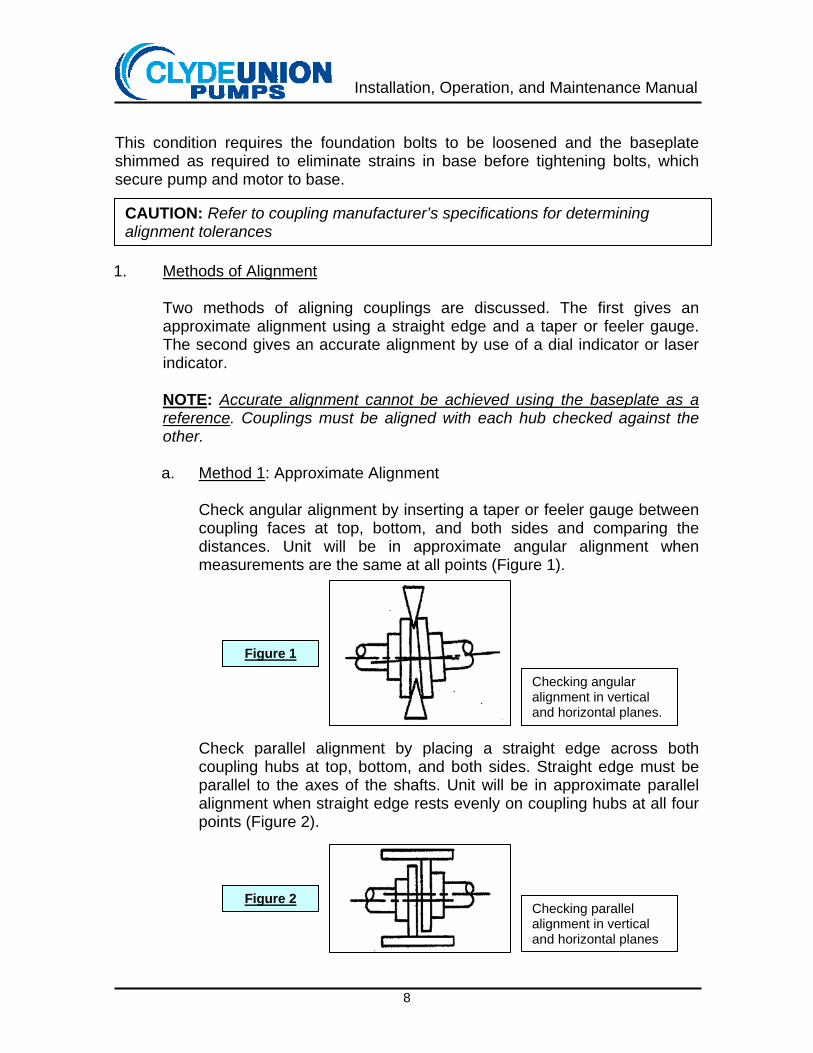
Check angular alignment by inserting a taper or feeler gauge between coupling faces at top, bottom, and both sides and comparing the distances. Unit will be in approximate angular alignment when measurements are the same at all points (Figure 1).
Check parallel alignment by placing a straight edge across both coupling hubs at top, bottom, and both sides. Straight edge must be parallel to the axes of the shafts. Unit will be in approximate parallel alignment when straight edge rests evenly on coupling hubs at all four points (Figure 2).
CAUTION: Refer to coupling manufacturer’s specifications for determining alignment tolerances
Checking angular alignment in vertical and horizontal planes.
Figure 1
Checking parallel alignment in vertical and horizontal planes
Figure 2
Installation, Operation, and Maintenance Manual
9
Correct the angular and parallel alignment by means of shims under driver or by sliding driver in the horizontal plane. After each adjustment, recheck alignment. Adjustment in one direction may disturb adjustments already made in another. It should not be necessary to shim under the pump.
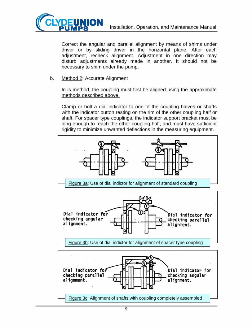
b. Method 2: Accurate Alignment
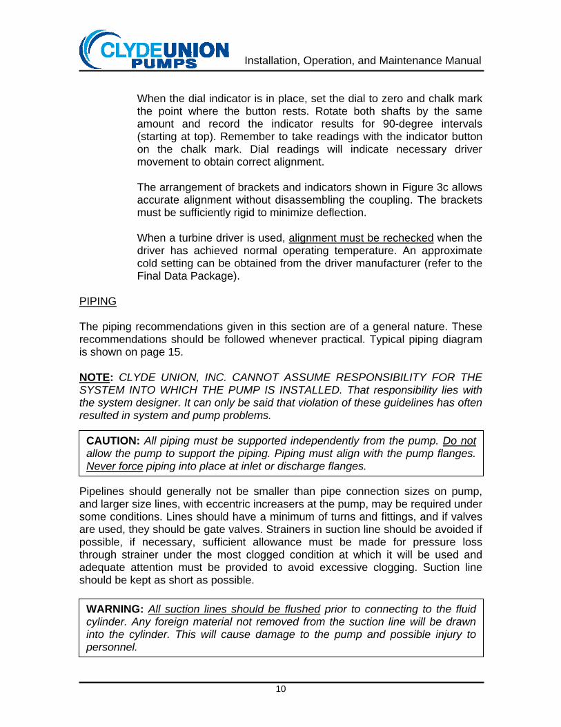
In is method, the coupling must first be aligned using the approximate methods described above. Clamp or bolt a dial indicator to one of the coupling halves or shafts with the indicator button resting on the rim of the other coupling half or shaft. For spacer type couplings, the indicator support bracket must be long enough to reach the other coupling half, and must have sufficient rigidity to minimize unwanted deflections in the measuring equipment.
Figure 3a: Use of dial indictor for alignment of standard coupling
Figure 3b: Use of dial indictor for alignment of spacer type coupling
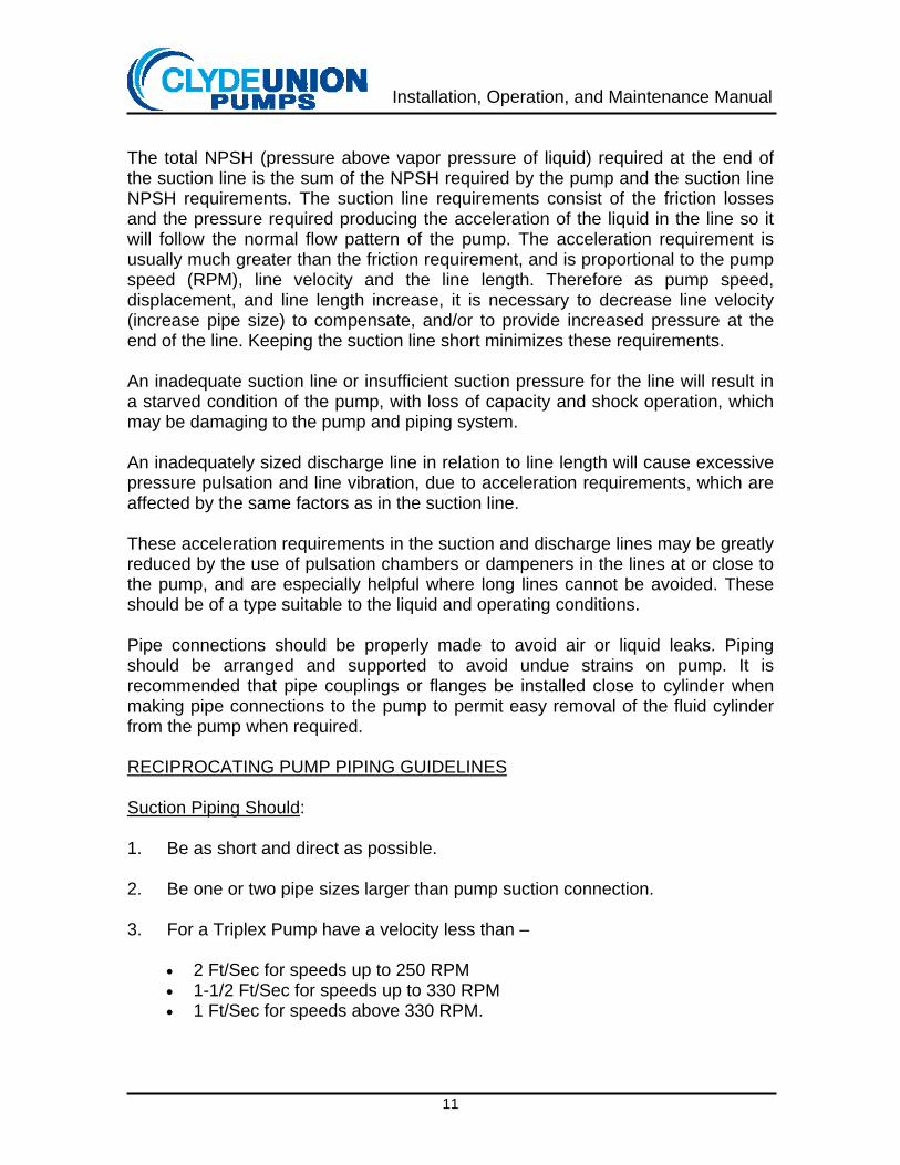
Figure 3c: Alignment of shafts with coupling completely assembled
Installation, Operation, and Maintenance Manual
10
When the dial indicator is in place, set the dial to zero and chalk mark the point where the button rests. Rotate both shafts by the same amount and record the indicator results for 90-degree intervals (starting at top). Remember to take readings with the indicator button on the chalk mark. Dial readings will indicate necessary driver movement to obtain correct alignment. The arrangement of brackets and indicators shown in Figure 3c allows accurate alignment without disassembling the coupling. The brackets must be sufficiently rigid to minimize deflection. When a turbine driver is used, alignment must be rechecked when the driver has achieved normal operating temperature. An approximate cold setting can be obtained from the driver manufacturer (refer to the Final Data Package).
PIPING The piping recommendations given in this section are of a general nature. These recommendations should be followed whenever practical. Typical piping diagram is shown on page 15. NOTE: CLYDE UNION, INC. CANNOT ASSUME RESPONSIBILITY FOR THE SYSTEM INTO WHICH THE PUMP IS INSTALLED. That responsibility lies with the system designer. It can only be said that violation of these guidelines has often resulted in system and pump problems. Pipelines should generally not be smaller than pipe connection sizes on pump, and larger size lines, with eccentric increasers at the pump, may be required under some conditions. Lines should have a minimum of turns and fittings, and if valves are used, they should be gate valves. Strainers in suction line should be avoided if possible, if necessary, sufficient allowance must be made for pressure loss through strainer under the most clogged condition at which it will be used and adequate attention must be provided to avoid excessive clogging. Suction line should be kept as short as possible.
CAUTION: All piping must be supported independently from the pump. Do not allow the pump to support the piping. Piping must align with the pump flanges. Never force piping into place at inlet or discharge flanges.
WARNING: All suction lines should be flushed prior to connecting to the fluid cylinder. Any foreign material not removed from the suction line will be drawn into the cylinder. This will cause damage to the pump and possible injury to personnel.
Installation, Operation, and Maintenance Manual
11
The total NPSH (pressure above vapor pressure of liquid) required at the end of the suction line is the sum of the NPSH required by the pump and the suction line NPSH requirements. The suction line requirements consist of the friction losses and the pressure required producing the acceleration of the liquid in the line so it will follow the normal flow pattern of the pump. The acceleration requirement is usually much greater than the friction requirement, and is proportional to the pump speed (RPM), line velocity and the line length. Therefore as pump speed, displacement, and line length increase, it is necessary to decrease line velocity (increase pipe size) to compensate, and/or to provide increased pressure at the end of the line. Keeping the suction line short minimizes these requirements. An inadequate suction line or insufficient suction pressure for the line will result in a starved condition of the pump, with loss of capacity and shock operation, which may be damaging to the pump and piping system. An inadequately sized discharge line in relation to line length will cause excessive pressure pulsation and line vibration, due to acceleration requirements, which are affected by the same factors as in the suction line. These acceleration requirements in the suction and discharge lines may be greatly reduced by the use of pulsation chambers or dampeners in the lines at or close to the pump, and are especially helpful where long lines cannot be avoided. These should be of a type suitable to the liquid and operating conditions. Pipe connections should be properly made to avoid air or liquid leaks. Piping should be arranged and supported to avoid undue strains on pump. It is recommended that pipe couplings or flanges be installed close to cylinder when making pipe connections to the pump to permit easy removal of the fluid cylinder from the pump when required. RECIPROCATING PUMP PIPING GUIDELINES Suction Piping Should: 1. Be as short and direct as possible. 2. Be one or two pipe sizes larger than pump suction connection. 3. For a Triplex Pump have a velocity less than –
• 2 Ft/Sec for speeds up to 250 RPM • 1-1/2 Ft/Sec for speeds up to 330 RPM • 1 Ft/Sec for speeds above 330 RPM.
Installation, Operation, and Maintenance Manual
12
4. Contain a minimum number of turns. Necessary turns should be accom-
plished with long-radius elbows or laterals. 5. Be designed to preclude the collection of vapor in the piping. (No high points
unless vented.) (Use eccentric reducer at pump cylinder with flat side up.) 6. Be designed so that acceleration head (Ha), friction loss (Hf), and pump
NPSH required (NPSHR) do not exceed the NPSH available (NPSHA) from the system. Acceleration head is defined and discussed in the Hydraulic Institute Standards. In equation form:
Ha + Hf + NPSHR < NPSHA
7. Include a suction bottle or suitable pulsation dampener installed adjacent to
pump cylinder if it is found that the acceleration head is excessive. Care must be taken in the application of dampeners to suction systems since many dampeners are not suitable for low-pressure application.
Discharge Piping Should: 1. Be as short and direct as possible. 2. Be one to two pipe sizes larger than pump discharge connection. 3. Have a velocity not exceeding three times the suction velocity. 4. Contain a minimum number of turns, utilizing long-radius elbows and laterals
where possible. 5. Include a suitable pulsation dampener or provisions for adding a dampener
later adjacent to the pump cylinder. 6. A relief valve should be provided between pump and check or shut-off valve,
close to pump. It must be sized to pass the entire pump capacity with a cracking pressure set about 10% over specified discharge pressure, and an accumulation pressure not exceeding 10% of cracking pressure.
7. A by-pass line, with a shut-off valve should be provided from discharge line to
suction supply source (connected between pump and check valve). It serves the purposes of permitting lubrication to reach critical pump parts during start-up without subjecting these parts to high leads, permitting driver to reach full speed under low torque conditions, and permitting all pumping chambers of fluid end to become fully primed.
WARNING: This positive displacement machine should not be operated against a dead end discharge.

Installation, Operation, and Maintenance Manual
13
Multiple Units: When two or more pumps are connected to a common suction and/or discharge line, the capacities of all pumps (which run simultaneously) must be added for determination of line velocities. Care must be exercised to prevent a mutually reinforcing pressure wave from multiple units. To avoid this possibility, independent lines are often installed. The above guidelines represent a combination of Hydraulic Institute recom-mendations and criteria established by experienced designers of systems containing reciprocating pumps. NOTE: CLYDE UNION, INC. CANNOT ASSUME RESPONSIBILITY FOR THE SYSTEM INTO WHICH THE PUMP IS INSTALLED. That responsibility must lie with the system designer. The above guidelines are offered only as an aid to those involved in the system design. Acceleration Head Phenomenon Piping for a reciprocating pump requires more consideration than piping for a centrifugal pump, because the fluid in the suction line is pulsating (accelerating and decelerating); a certain amount of energy is required to produce the acceleration. This energy is in addition to the friction loss and is usually referred to as “Acceleration Head”. If sufficient energy is not available to accelerate the liquid in the suction line, the liquid will flash, the suction and discharge lines may shake, and the pump will operate noisily. It is possible to fracture a fluid cylinder with the high-pressure surges that occur in the cylinder when the fluid is flashing in the suction line.
Installation, Operation, and Maintenance Manual
14
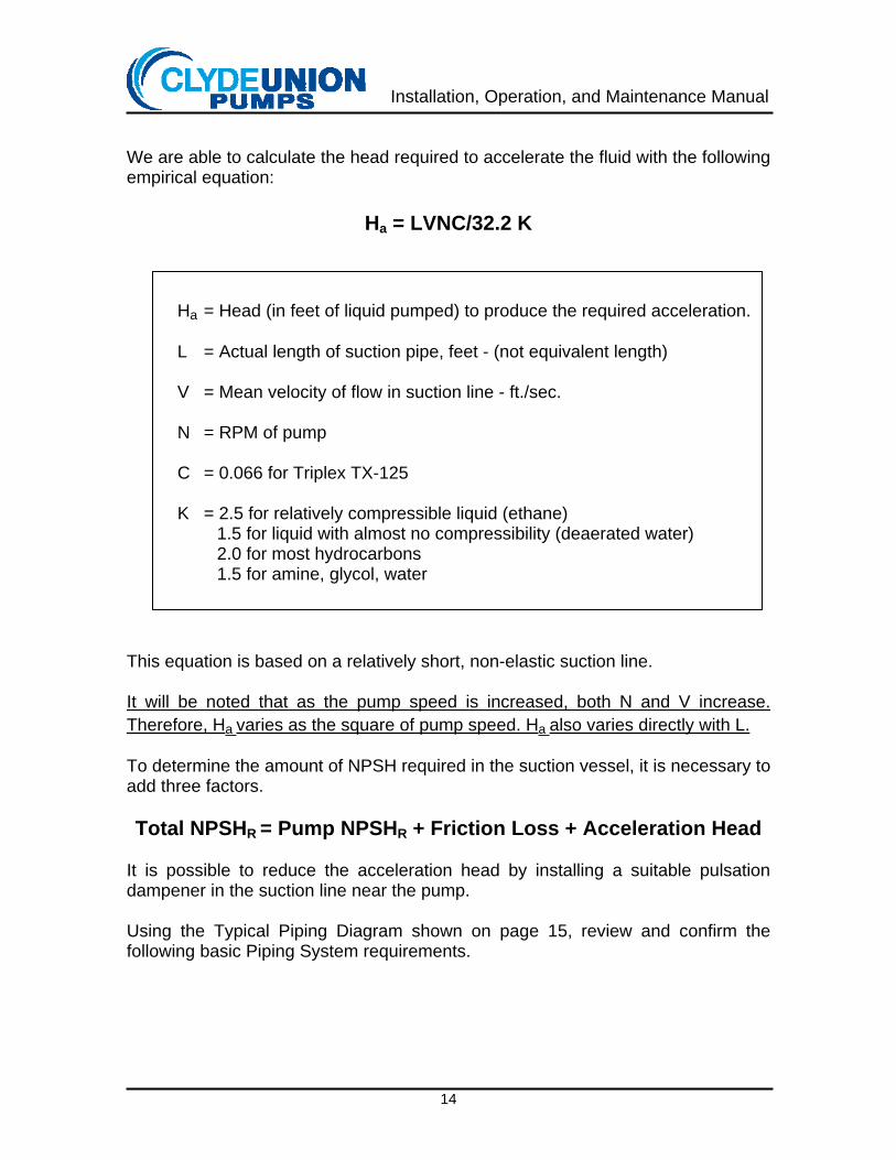
We are able to calculate the head required to accelerate the fluid with the following empirical equation:
Ha = LVNC/32.2 K
This equation is based on a relatively short, non-elastic suction line. It will be noted that as the pump speed is increased, both N and V increase. Therefore, Ha varies as the square of pump speed. Ha also varies directly with L. To determine the amount of NPSH required in the suction vessel, it is necessary to add three factors. Total NPSHR = Pump NPSHR + Friction Loss + Acceleration Head
It is possible to reduce the acceleration head by installing a suitable pulsation dampener in the suction line near the pump. Using the Typical Piping Diagram shown on page 15, review and confirm the following basic Piping System requirements.
Ha = Head (in feet of liquid pumped) to produce the required acceleration. L = Actual length of suction pipe, feet - (not equivalent length) V = Mean velocity of flow in suction line - ft./sec. N = RPM of pump C = 0.066 for Triplex TX-125 K = 2.5 for relatively compressible liquid (ethane)
1.5 for liquid with almost no compressibility (deaerated water) 2.0 for most hydrocarbons 1.5 for amine, glycol, water
Installation, Operation, and Maintenance Manual
15
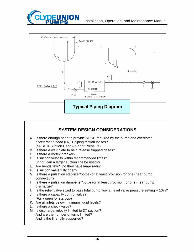
SYSTEM DESIGN CONSIDERATIONS
A. Is there enough head to provide NPSH required by the pump and overcome
acceleration head (HA) + piping friction losses? (NPSH = Suction Head – Vapor Pressure)
B. Is there a weir plate to help release trapped gases? C. Is there a vortex breaker? D. Is suction velocity within recommended limits?
(If not, can a larger suction line be used?) E. Are bends few? Do they have large radii? F. Is suction valve fully open? G. Is there a pulsation stabilizer/bottle (or at least provision for one) near pump
connection? H. Is there a pulsation dampener/bottle (or at least provision for one) near pump
discharge? I. Is the relief valve sized to pass total pump flow at relief valve pressure setting + 10%? J. Is there a capacity control valve?
(Fully open for start-up) K. Are all inlets below minimum liquid levels? L. Is there a check valve? M. Is discharge velocity limited to 3X suction?
And are the number of turns limited? And is the line fully supported?
Typical Piping Diagram

Installation, Operation, and Maintenance Manual
16
SECTION II - OPERATION
PREPARATION FOR START-UP 1. Removal of Protective Coating
Remove all protective coatings that have been applied to the pump, which would interfere with pump operation. All exposed machined surfaces are coated before shipment and this coating is soluble in petroleum solvents. Of particular importance are crosshead stubs. They should be clean and smooth to prevent damage to oil seals.
2. Inspection After Storage
If the pump has been in storage or idle for a long period, the drive and fluid end should be inspected to make sure that no dirt or debris has accumulated in them. This can be done by removing the crankcase cover and fluid cylinder covers, and making a visual check.
3. Final Piping Checks
Make sure all piping joints are tight (including drains) so they do not permit any leakage of liquids out of, or air into, the piping system. Verify that a relief valve is installed in the discharge line, and is set to the correct pressure.
4. Crankcase Oil
Fill crankcase to proper level indicated on oil level gauge. The oil level should be maintained to within ½-inch of the top of oil level gauge at side of frame. Make first oil change after 125 - 175 hours of operation. When changing, remove crankcase cover and clean crank and gear case. Make subsequent changes every six months or 2,500 hours of operation, whichever occurs first or oftener if conditions permit excessive water or other contamination. Clean crank and gear case at least once a year - inspect interior parts and tighten lubricator drive chain adjustment should excessive looseness develop.
CAUTION: The importance of having the unit clean prior to initial operation cannot be overemphasized.
WARNING: All suction lines should be flushed prior to connecting to the fluid cylinder. Any foreign material not removed from the suction line will be drawn into the cylinder. This will cause damage to the pump and possible injury to personnel.
Installation, Operation, and Maintenance Manual
17
When draining oil, drain both from bottom of gear case, and from bottom of crankcase at opposite side of frame from gear case. When refilling put in 1/2 gallon through plugged opening at top of gear case and remainder into crankcase through plugged opening at top of crankcase at opposite side of frame from gear case until oil level is to top of gauge. Approximately 10 gallons required for the TX-125, TX-150, and TX-200. When adding make-up oil, add only to crankcase, as gear case oil level is automatically controlled.
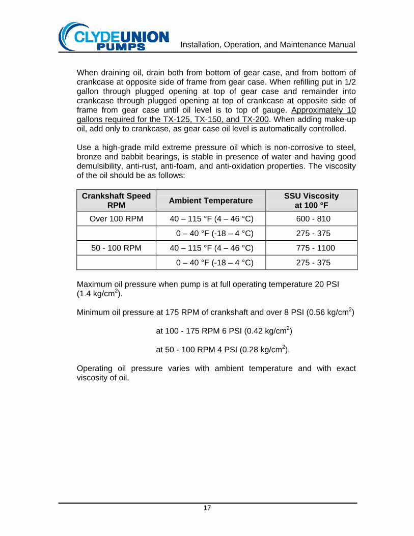
Use a high-grade mild extreme pressure oil which is non-corrosive to steel, bronze and babbit bearings, is stable in presence of water and having good demulsibility, anti-rust, anti-foam, and anti-oxidation properties. The viscosity of the oil should be as follows:
Crankshaft Speed RPM Ambient Temperature SSU Viscosity
at 100 °F Over 100 RPM 40 – 115 °F (4 – 46 °C) 600 - 810
0 – 40 °F (-18 – 4 °C) 275 - 375
50 - 100 RPM 40 – 115 °F (4 – 46 °C) 775 - 1100
0 – 40 °F (-18 – 4 °C) 275 - 375
Maximum oil pressure when pump is at full operating temperature 20 PSI (1.4 kg/cm2). Minimum oil pressure at 175 RPM of crankshaft and over 8 PSI (0.56 kg/cm2)
at 100 - 175 RPM 6 PSI (0.42 kg/cm2) at 50 - 100 RPM 4 PSI (0.28 kg/cm2).
Operating oil pressure varies with ambient temperature and with exact viscosity of oil.
Installation, Operation, and Maintenance Manual
18
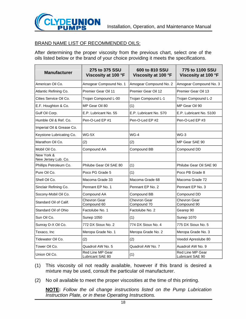
BRAND NAME LIST OF RECOMMENDED OILS: After determining the proper viscosity from the previous chart, select one of the oils listed below or the brand of your choice providing it meets the specifications.
Manufacturer 275 to 375 SSU Viscosity at 100 °F
600 to 810 SSU Viscosity at 100 °F
775 to 1100 SSU Viscosity at 100 °F
American Oil Co. Amogear Compound No. 1 Amogear Compound No. 2 Amogear Compound No. 3
Atlantic Refining Co. Premier Gear Oil 11 Premier Gear Oil 12 Premier Gear Oil 13
Cities Service Oil Co. Trojan Compound L-00 Trojan Compound L-1 Trojan Compound L-2
E.F. Houghton & Co. MP Gear Oil 80 (1) MP Gear Oil 90
Gulf Oil Corp. E.P. Lubricant No. 55 E.P. Lubricant No. S70 E.P. Lubricant No. S100
Humble Oil & Ref. Co. Pen-O-Led EP #1 Pen-O-Led EP #2 Pen-O-Led EP #3
Imperial Oil & Grease Co.
Keystone Lubricating Co. WG-5X WG-4 WG-3
Marathon Oil Co. (2) (2) MP Gear SAE 90
Mobil Oil Co. Compound AA Compound BB Compound DD New York & New Jersey Lub. Co.
Phillips Petroleum Co. Philube Gear Oil SAE 80 (1) Philube Gear Oil SAE 90
Pure Oil Co. Poco PG Grade 5 (1) Poco PB Grade 8
Shell Oil Co. Macoma Grade 33 Macoma Grade 68 Macoma Grade 72
Sinclair Refining Co. Pennant EP No. 1 Pennant EP No. 2 Pennant EP No. 3
Socony-Mobil Oil Co. Compound AA Compound BB Compound DD
Standard Oil of Calif. Chevron Gear Compound 60
Chevron Gear Compound 70
Chevron Gear Compound 90
Standard Oil of Ohio Factolube No. 1 Factolube No. 2 Gearep 90
Sun Oil Co. Sunep 1050 (1) Sunep 1070
Sunray D-X Oil Co. 772 DX Sioux No. 2 774 DX Sioux No. 4 775 DX Sioux No. 5
Texaco, Inc Meropa Grade No. 1 Meropa Grade No. 2 Meropa Grade No. 3
Tidewater Oil Co. (2) (2) Veedol Apreslube 80
Tower Oil Co. Quadroil AW No. 5 Quadroil AW No. 7 Auadroil AW No. 9
Union Oil Co. Red Line MP Gear Lubricant SAE 80 (1) Red Line MP Gear
Lubricant SAE 90 (1) This viscosity oil not readily available, however if this brand is desired a
mixture may be used, consult the particular oil manufacturer. (2) No oil available to meet the proper viscosities at the time of this printing.
NOTE: Follow the oil change instructions listed on the Pump Lubrication Instruction Plate, or in these Operating Instructions.
Installation, Operation, and Maintenance Manual
19
5. V-Belt Installation and Adjustment
If the pump is V-belt driven, be sure belts and sheaves are clean (free of all paint, grease, or dirt). Remove any rust or burrs in the sheave grooves caused by handling. Be sure the drive rotates freely, and has sufficient clearance around all components. Install and adjust V-belts per the following instructions.
a. Installation
1. Move motor toward pump until belts can be easily installed by hand.
2. Move motor away from pump until belts are tight (see “Adjustment” section).
3. Check to be sure that motor and pump shafts are parallel.
4. Keep belts free from dirt and oil.
WARNING: Be sure that power to the motor is off and locked out before removing the V-belt guard and performing maintenance on the belts and sheaves.
CAUTION: Do not combine used and new belts on one drive. Keep used belts for emergency replacement only. Use only a matched set of new belts.
CAUTION: Do not pry or roll belts on as this may damage belts.
CAUTION: Do not use belt dressing.

Installation, Operation, and Maintenance Manual
20
b. Adjustment
1. Adjust drive to obtain all belt slack on one side of span.
2. Measure the span.
3. Multiply by 1/64. (This is proper deflection)
4. Tighten drive until proper belt deflection is obtained.
5. Measure each belt individually. Tension must be the same for all belts in drive.
NOTE: V-belts must be operated under proper tension. Too little tension will permit excessive slippage resulting in loss of life and power. Too much tension will cause short life. Proper tension is just slightly above the point where slip is eliminated. This can best be determined by measuring speed ratio at no load and at full load. The change in speed between no load and full load should not exceed one percent. During the first 36 hours of operation, the tension must be adjusted to compensate for initial stretch and wearing-in or seating of the belts in the grooves. Spare belts should be stored in a cool, dry area.
SMALL PULLEY DIAMETER FORCE * CROSS SECTION
inch millimeters pound Newton
3V 2.65 - 3.65 67 - 93 3 - 4 13 - 18
3V 4.12 - 6.90 105 - 175 5 - 7.5 22 - 33
5V 7.10 - 10.90 180 - 277 13 - 20 58 - 89
5V 11.80 - 16.00 300 - 406 15 - 23 67 - 100
8V 12.50 - 17.00 320 - 430 28 - 42 125 - 185
8V 18.00 - 22.40 460 - 570 33 - 50 145 - 220
* A new set of belts should be tensioned 1/3 greater than the force listed below.

Installation, Operation, and Maintenance Manual
21
6. Direction of Rotation
The proper rotation is so that the top of the crankshaft moves toward the fluid end.
NOTE: Pinion shaft must rotate opposite of crankshaft as indicated by rotation arrow on the pump.
7. If the pump was shipped from the factory with plungers and packing not
installed, perform packing/plunger installation (see Disassembly / Assembly instructions, page 33).
INSTRUCTIONS - OIL PRESSURE FAILURE PROTECTION All Clyde Union, Inc. TX-125, TX-150, and TX-200 pumps are equipped with a pressure switch to safeguard against damage from oil pressure failure. Any drop of pressure below the predetermined setting will actuate this switch and may be wired to shut off the driver. A warning horn or a warning light may also be incorporated. The switch is an Allen Bradley Bulletin 836 Style T, bellows type, employing snap action precision nickel contacts. ELECTRIC HOOKUP Access to the contact terminals is made by removing the top nameplate cover. (In switches with explosion proof enclosure, first remove the four 5/16-18 NC x 7/8 cap screws and slide off the explosion proof cover.) Wiring methods should conform to the applicable codes. SWITCH ADJUSTMENT As used on this application, the switch should (1) be adjusted to actuate on falling pressure at 4 PSIG (0.28 kg/cm2) and (2) have a minimum “Differential”. These adjustments have been made by Clyde Union, Inc. before mounting on the pump. Should it be required to check adjustments, the following procedure should be followed: The first adjustment to check is the “Differential”. This is the spread between the actuation point on falling pressure and the (higher) actuation point on rising pressure. This “Differential” should be a small as possible. Proper adjustment of this setting is described on the instruction sticker on the underside of the cover. By turning the slotted screw counter-clockwise, the “Differential” will be decreased.
CAUTION: Liquid will be pumped in the fluid end regardless of the direction of crankshaft rotation. However, the wrong rotation will result in no lubrication of the power end components and a short pump life.

Installation, Operation, and Maintenance Manual
22
The second adjustment to check is the actuation setting. The pump must be stopped so that the pressure on the switch is 0 PSIG (0 kg/cm2). If a source of compressed air is available and can be supplied to the switch at 4 PSIG (0.28 kg/cm2), greater accuracy in the adjustment can be made; however, this is not essential. Adjustment of the actuation setting is made by turning the slotted shaft protruding through the top of the switch casing (after first loosening the locknut). Turn clockwise to increase setting, counter-clockwise to decrease it. This setting cannot be accurately made from the scale adjacent to the left window. Instead, use the following steps: 1. Turn the actuation-adjusting shaft counter-clockwise until the indicator is
positioned near the bottom of the right hand window. This is the actuation, which takes place on rising pressure.
2. Turn the actuation-adjusting shaft clockwise slowly until the indicator snaps to
a position near the top of the right hand window. Do not turn further. This is the actuation, which takes place on falling pressure.
3. If a controlled air pressure of 4 PSIG (0.28 kg /cm2) for switch adjustment is
supplied, no further adjusting is necessary and the locknut may be tightened.
If atmospheric pressure is used, 0 PSIG (0.0 kg/cm2), the actuation adjusting shaft should be rotated 3/4 turn clockwise to change the setting from 0 PSIG (0.0 kg/cm2) to approximately 4 PSIG (0.28 kg/cm2).
START UP AFTER PUMP IS STOPPED To start the pump after shut down, some provision must be made to lock-in the circuit that was opened and lock-out the circuit that was closed until pump oil pressure raises high enough to actuate the switch. For an installation of continuous service, the motor starter button can be held manually to accomplish this, or a time delay contact may be used. For an automatic start-stop service, use of a time delay switch is necessary (see the following diagrams).
CAUTION: Do not allow this screw to extend above the ground surface because it will then interfere with proper gasketing of the cover.
Installation, Operation, and Maintenance Manual
23
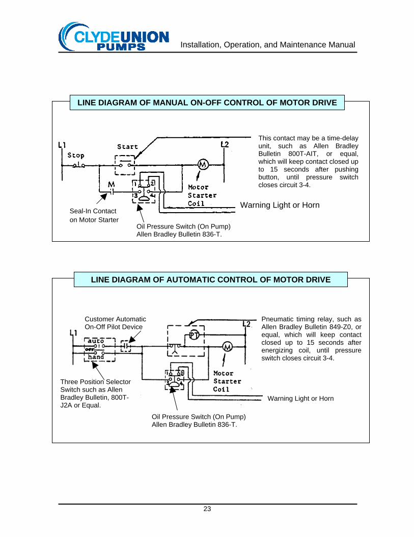
This contact may be a time-delay unit, such as Allen Bradley Bulletin 800T-AIT, or equal, which will keep contact closed up to 15 seconds after pushing button, until pressure switch closes circuit 3-4.
Oil Pressure Switch (On Pump) Allen Bradley Bulletin 836-T.
Warning Light or Horn Seal-In Contact on Motor Starter
LINE DIAGRAM OF MANUAL ON-OFF CONTROL OF MOTOR DRIVE
Pneumatic timing relay, such as Allen Bradley Bulletin 849-Z0, or equal, which will keep contact closed up to 15 seconds after energizing coil, until pressure switch closes circuit 3-4.
Customer Automatic On-Off Pilot Device
Warning Light or Horn
Three Position Selector Switch such as Allen Bradley Bulletin, 800T-J2A or Equal.
Oil Pressure Switch (On Pump) Allen Bradley Bulletin 836-T.
LINE DIAGRAM OF AUTOMATIC CONTROL OF MOTOR DRIVE
Installation, Operation, and Maintenance Manual
24
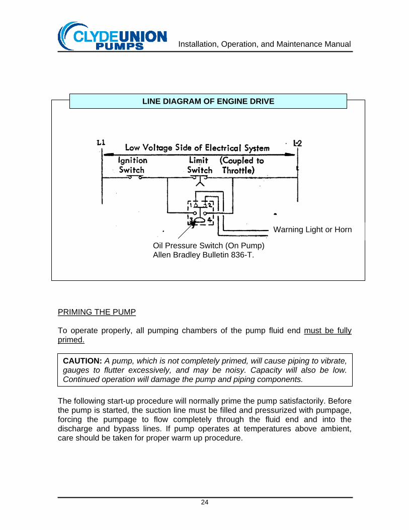
PRIMING THE PUMP To operate properly, all pumping chambers of the pump fluid end must be fully primed.
The following start-up procedure will normally prime the pump satisfactorily. Before the pump is started, the suction line must be filled and pressurized with pumpage, forcing the pumpage to flow completely through the fluid end and into the discharge and bypass lines. If pump operates at temperatures above ambient, care should be taken for proper warm up procedure.
CAUTION: A pump, which is not completely primed, will cause piping to vibrate, gauges to flutter excessively, and may be noisy. Capacity will also be low. Continued operation will damage the pump and piping components.
Warning Light or Horn
Oil Pressure Switch (On Pump) Allen Bradley Bulletin 836-T.
LINE DIAGRAM OF ENGINE DRIVE
Installation, Operation, and Maintenance Manual
25
High Temperature Operation Pumps handling liquids at temperatures above 300 °F (150 °C) should be brought up to operating temperature before start-up. This can be accomplished by circulating hot pumpage through the pump. Control the circulation so that the pump temperature rise does not exceed 150 °F (37.8 °C) per hour. The pump temperature must be within 75 °F (24 °C) of the pumpage before start-up and operation. START-UP After all checks have been made, you are ready to start the pump. 1. Normal Start-Up
Prior to start-up, the by-pass valve, suction block valve, and discharge block valve MUST BE FULLY OPEN. Start pump and operate a few minutes with no load to allow lubrication to reach power end components and to allow fluid end to become completely primed. Then slowly close by-pass valve, allowing pump to be gradually loaded.
2. Avoid Starting Pump Under Load
CAUTION: Starting a power pump under load is a poor practice and should be avoided.
Installation, Operation, and Maintenance Manual
26
BREAK-IN PERIOD Be sure oil level is at or near top of oil gauge at side of pump. If ambient temperature is below 40 °F (4 °C), change oil to oil of proper viscosity. See instructions under “Lubrication” for proper oil. Run new pump idle, without hydraulic load, for at least 3 hours before applying load. If possible, after idle run, run pump for 8 or more additional hours with approximately half the operating pressure, or better still, build up pressure gradually to full operating pressure over approximately an 8-hour period. If not possible to run pump at partial load or with gradually increasing load after idle run, apply full load after idle run for a period of one hour, shut pump down for one hour; run for 2 hours until full load, shut pump down for one hour; run for 4 hours under load, shut down for one hour; after which pump may be put in regular service. Whenever pump has been idle for more that 5 hours, run pump idle for a few minutes to establish thorough lubrication before applying load, and if ambient temperature is less than 70 °F (21 °C), or until crankcase cover feels warm to the hand.
The disadvantages of starting under load are:
a. Oil is not flowing through pump lubrication system.
b. Bearings have not had an opportunity to establish an oil film.
c. The load on bearings, power end components, and fluid end components will be higher than operation loads because of the inertia of all rotating parts and the inertia of all fluid in suction and discharge lines. This fluid inertia can be quite large for long lines.
d. Drive components (gears, belts, and couplings) will be loaded
above their design because of inertia mentioned above.
e. Motor may be loaded beyond its capacity.
f. Not all pumping chambers of the fluid end have an opportunity to become primed. This can lead to reduced capacity and severe vibration in suction and discharge piping.
Installation, Operation, and Maintenance Manual
27
Pump must be stopped when load is applied unless a suitable arrangement is provided to permit application of load without resulting shock when load is applied with pump operating. Never start or run pump with starved suction or closed suction line unless pump is fully relieved of discharge pressure. Never start pump with closed discharge line, and do not close line while pump is running. See instructions under “Relief Valve and Bypass”. Any unit that has undergone a major repair to the power frame requires a break-in period before it is placed back into service. ABNORMAL ENVIRONMENTAL CONDITIONS 1. Freezing Conditions
To prevent freezing of liquids in fluid cylinder and lubricating oils from becoming too viscous, the pump should be protected from freezing temperatures. If exposure to temperatures below 30 ºF (0 ºC) is unavoidable, provisions must be made to warm the power end and fluid end. If pumpage will freeze during shut-down periods, the entire system must be drained to prevent damage to pump and piping.
2. Dusty Conditions
Air-borne abrasives will deposit themselves on plungers and crosshead stubs, shortening the lives of plungers, packing, stubs, and seals; and may be drawn through the power end breather, contaminating oil and shortening bearing life. Efforts should be made to protect the pump against dust and grit.
3. Corrosive Vapors
Efforts should be made to minimize the exposure of the pump to corrosive gases to prevent contamination of power end and lubricator lubricants.
4. High Humidity
Pumps exposed to high humidity, unless operated continuously, will accumulate condensation in the power end and lubricator. Periodic samples of oil should be taken from drain connections, and when water is detected, the oil should be changed.
5. Pressurizing Power End
Pressurizing the power end to exclude contaminants requires a special oil level gauge.
CAUTION: Do not attempt pressurization of power end with the standard oil level gauge. All oil will be forced out through the vent hole in the top of the gauge.

Installation, Operation, and Maintenance Manual
28
TROUBLE CHECKLIST See Items/Remedies Symptom or Trouble and Probable Causes on pages 30 - 31 Low Discharge Pressure
Clogged suction system...................................................................................7 Worn nozzles or orifices (Jet cleaning applications) ........................................1 Worn seat or stem in pressure regulator or relief valve ...................................3 Pump not fully primed....................................................................................10 Low pump speed .............................................................................................2 Motor improperly wired ..................................................................................28 Excessive packing leakage..............................................................................5 Foreign material under pump valves ...............................................................6
Low Capacity
Clogged suction system...................................................................................7 Foreign material under pump valves ...............................................................6 Low pump speed .............................................................................................2 Gas entering fluid cylinder ...............................................................................8 Insufficient suction pressure ............................................................................9 Pump not fully primed....................................................................................10
Knocking in Power End
Low oil level ...................................................................................................11 Crankshaft bearings out of adjustment ..........................................................12 Loose plunger or plunger stub .......................................................................13 Pump running backwards ..............................................................................25 Worn crosshead pin bearings ........................................................................14 Loose sheaves or bushings .............................................................................4 Sound being transmitted from fluid end ................................. See Next Section
Knocking or Pounding in Fluid End or Excessive Pulsations
Insufficient NPSHA...........................................................................................9 Gas entering fluid cylinder ...............................................................................8 Broken valve spring or foreign material under valve........................................6 Excessive valve lift ........................................................................................21 Relief valve or other accessories in discharge piping causing noise .............19
Installation, Operation, and Maintenance Manual
29
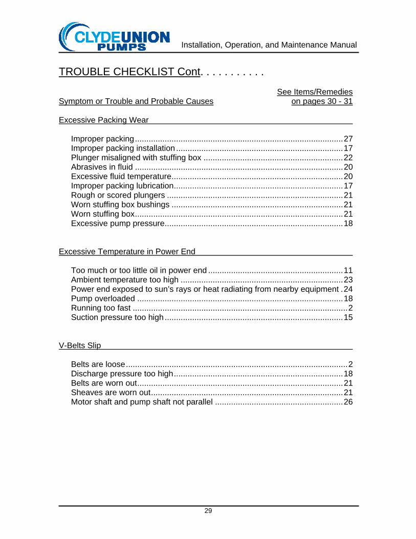
TROUBLE CHECKLIST Cont. . . . . . . . . . . See Items/Remedies Symptom or Trouble and Probable Causes on pages 30 - 31 Excessive Packing Wear
Improper packing...........................................................................................27 Improper packing installation .........................................................................17 Plunger misaligned with stuffing box .............................................................22 Abrasives in fluid ...........................................................................................20 Excessive fluid temperature...........................................................................20 Improper packing lubrication..........................................................................17 Rough or scored plungers .............................................................................21 Worn stuffing box bushings ...........................................................................21 Worn stuffing box...........................................................................................21 Excessive pump pressure..............................................................................18
Excessive Temperature in Power End
Too much or too little oil in power end ...........................................................11 Ambient temperature too high .......................................................................23 Power end exposed to sun’s rays or heat radiating from nearby equipment .24 Pump overloaded ..........................................................................................18 Running too fast ..............................................................................................2 Suction pressure too high ..............................................................................15
V-Belts Slip
Belts are loose.................................................................................................2 Discharge pressure too high..........................................................................18 Belts are worn out..........................................................................................21 Sheaves are worn out....................................................................................21 Motor shaft and pump shaft not parallel ........................................................26
Installation, Operation, and Maintenance Manual
30
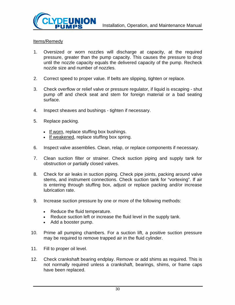
Items/Remedy 1. Oversized or worn nozzles will discharge at capacity, at the required
pressure, greater than the pump capacity. This causes the pressure to drop until the nozzle capacity equals the delivered capacity of the pump. Recheck nozzle size and number of nozzles.
2. Correct speed to proper value. If belts are slipping, tighten or replace.
3. Check overflow or relief valve or pressure regulator, if liquid is escaping - shut
pump off and check seat and stem for foreign material or a bad seating surface.
4. Inspect sheaves and bushings - tighten if necessary.
5. Replace packing.
• If worn, replace stuffing box bushings. • If weakened, replace stuffing box spring.
6. Inspect valve assemblies. Clean, relap, or replace components if necessary.
7. Clean suction filter or strainer. Check suction piping and supply tank for
obstruction or partially closed valves.
8. Check for air leaks in suction piping. Check pipe joints, packing around valve stems, and instrument connections. Check suction tank for “vortexing”. If air is entering through stuffing box, adjust or replace packing and/or increase lubrication rate.
9. Increase suction pressure by one or more of the following methods:
• Reduce the fluid temperature. • Reduce suction left or increase the fluid level in the supply tank. • Add a booster pump.
10. Prime all pumping chambers. For a suction lift, a positive suction pressure
may be required to remove trapped air in the fluid cylinder.
11. Fill to proper oil level.
12. Check crankshaft bearing endplay. Remove or add shims as required. This is not normally required unless a crankshaft, bearings, shims, or frame caps have been replaced.
Installation, Operation, and Maintenance Manual
31
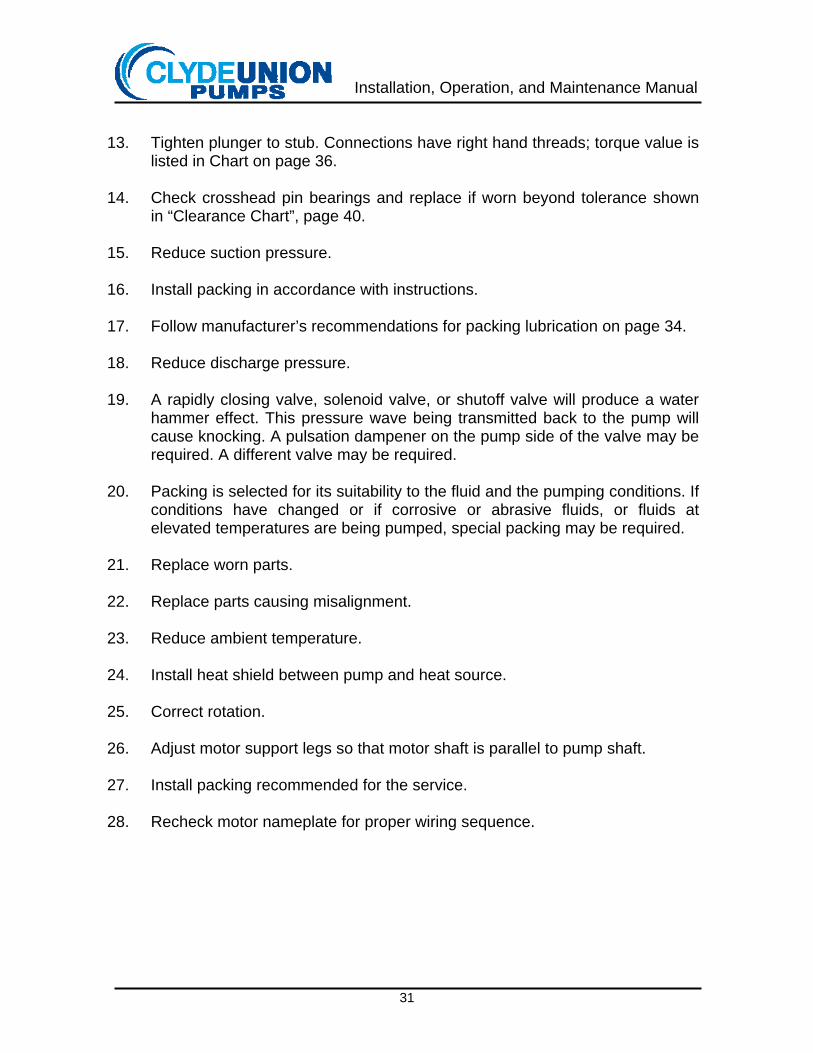
13. Tighten plunger to stub. Connections have right hand threads; torque value is
listed in Chart on page 36.
14. Check crosshead pin bearings and replace if worn beyond tolerance shown in “Clearance Chart”, page 40.
15. Reduce suction pressure.
16. Install packing in accordance with instructions.
17. Follow manufacturer’s recommendations for packing lubrication on page 34.
18. Reduce discharge pressure.
19. A rapidly closing valve, solenoid valve, or shutoff valve will produce a water
hammer effect. This pressure wave being transmitted back to the pump will cause knocking. A pulsation dampener on the pump side of the valve may be required. A different valve may be required.
20. Packing is selected for its suitability to the fluid and the pumping conditions. If
conditions have changed or if corrosive or abrasive fluids, or fluids at elevated temperatures are being pumped, special packing may be required.
21. Replace worn parts.
22. Replace parts causing misalignment.
23. Reduce ambient temperature.
24. Install heat shield between pump and heat source.
25. Correct rotation.
26. Adjust motor support legs so that motor shaft is parallel to pump shaft.
27. Install packing recommended for the service.
28. Recheck motor nameplate for proper wiring sequence.

Installation, Operation, and Maintenance Manual
32
SECTION III - ROUTINE MAINTENANCE
PERFORMANCE RECORDS A daily record of pump performance should be kept, particularly when more than one person operates the unit. The first clue that performance is deteriorating usually comes from a written record or log. Records should include any unusual changes in temperature or pressure, or strange noises. These indicate that servicing may be needed. ROUTINE INSPECTION AND SERVICING GENERAL: No piece of machinery can be expected to continue in satisfactory operation unless it receives proper and periodic attention. The following are recom-mendations for routine inspection and servicing under normal conditions. 1. Daily or Approximately Every 24 Hours of Operation
Check the pump to assure that: a. Operation is quiet and smooth. b. Operating temperatures are normal in both the power end and the fluid
end. c. Oil level in the crankcase is proper. d. There is no gasket leakage. e. The packing is not leaking excessively. (Some leaking is preferred for
cooling and lubrication.) f. There is no fluid accumulation in the plunger well.
g. Packing lubricator is filled to proper level. h. V-belts are not slipping. i. Operating pressures are not above specified values.
2. Weekly or Approximately Every 170 Hours of Operation
Check . . . a. The oil in the crankcase for water or other contaminants. This can be
done while the pump is running, by drawing a small sample from the drain connection.
b. Strainers and other piping components to see that they are not clogged. This can be done by monitoring the pressure drops across these devices.
c. Belt tension. Adjust if needed.

Installation, Operation, and Maintenance Manual
33
d. Plungers to see that they are all still securely fastened to the stubs. 3. Monthly or Approximately Every 750 Hours of Operation
Check . . .
a. All bolting, especially those on the fluid end of pump. Tighten if necessary. (Refer to the bolt torquing requirements)
b. The crankcase breather. Clean if necessary.
NOTE: It should be noted that depending on environmental conditions, this might need to be done more frequently.
4. Every 3 Months or Approximately Every 2,500 Hours of Operation
a. Change the oil in the pump. During the oil change, the crankcase cover should be removed, the interior wiped clean, and a visual check made for worn parts and other abnormal conditions. In addition, the torque on connecting rod bolts should be checked. (See bolt torquing requirements)
b. Replace plunger packing and bushings (if worn) if leakage is excessive. 5. Every 6 Months or Approximately Every 4,500 Hours of Operation
a. If needed, the sealing surfaces of the fluid cylinder valves and valve seats are to be refinished.
b. Replace any compressed or broken valve springs. c. Replace plungers if worn, scored, or otherwise damaged. d. Replace crosshead stub seals. e. Replace belts if slipping excessively.
6. Yearly or Approximately Every 9,000 Hours of Operation
It is suggested that the pump be disassembled and thoroughly inspected. 7. Adjusting Periods for Inspection and Servicing
Severe environmental or operating conditions may require that the time intervals for inspection and servicing be shortened.
WARNING: Make sure power is off and locked in the off position.
WARNING: Make sure power is off and locked in the off position.
Installation, Operation, and Maintenance Manual
34
SECTION IV
DISASSEMBLY and ASSEMBLY INSTRUCTIONS
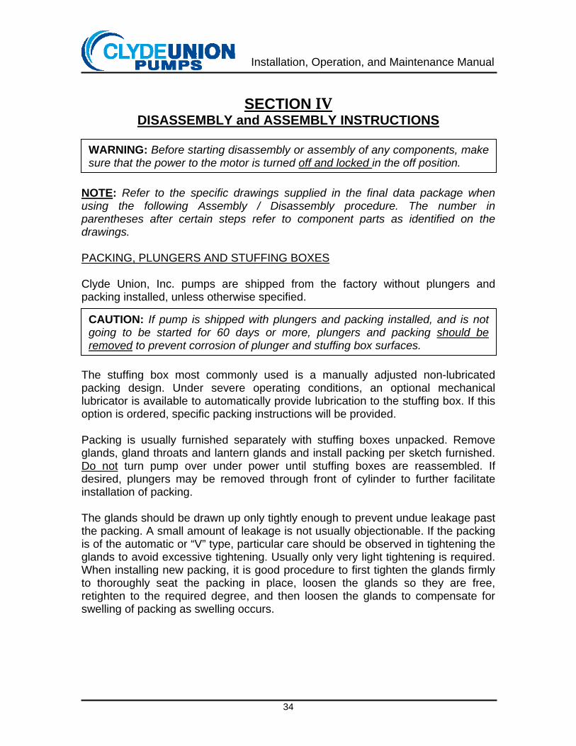
NOTE: Refer to the specific drawings supplied in the final data package when using the following Assembly / Disassembly procedure. The number in parentheses after certain steps refer to component parts as identified on the drawings. PACKING, PLUNGERS AND STUFFING BOXES Clyde Union, Inc. pumps are shipped from the factory without plungers and packing installed, unless otherwise specified. The stuffing box most commonly used is a manually adjusted non-lubricated packing design. Under severe operating conditions, an optional mechanical lubricator is available to automatically provide lubrication to the stuffing box. If this option is ordered, specific packing instructions will be provided. Packing is usually furnished separately with stuffing boxes unpacked. Remove glands, gland throats and lantern glands and install packing per sketch furnished. Do not turn pump over under power until stuffing boxes are reassembled. If desired, plungers may be removed through front of cylinder to further facilitate installation of packing. The glands should be drawn up only tightly enough to prevent undue leakage past the packing. A small amount of leakage is not usually objectionable. If the packing is of the automatic or “V” type, particular care should be observed in tightening the glands to avoid excessive tightening. Usually only very light tightening is required. When installing new packing, it is good procedure to first tighten the glands firmly to thoroughly seat the packing in place, loosen the glands so they are free, retighten to the required degree, and then loosen the glands to compensate for swelling of packing as swelling occurs.
WARNING: Before starting disassembly or assembly of any components, make sure that the power to the motor is turned off and locked in the off position.
CAUTION: If pump is shipped with plungers and packing installed, and is not going to be started for 60 days or more, plungers and packing should be removed to prevent corrosion of plunger and stuffing box surfaces.
Installation, Operation, and Maintenance Manual
35
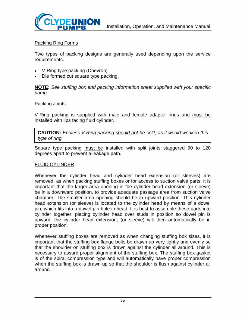
Packing Ring Forms Two types of packing designs are generally used depending upon the service requirements. • V-Ring type packing (Chevron). • Die formed cut square type packing. NOTE: See stuffing box and packing information sheet supplied with your specific pump. Packing Joints V-Ring packing is supplied with male and female adapter rings and must be installed with lips facing fluid cylinder. Square type packing must be installed with split joints staggered 90 to 120 degrees apart to prevent a leakage path. FLUID CYLINDER Whenever the cylinder head and cylinder head extension (or sleeves) are removed, as when packing stuffing boxes or for access to suction valve parts, it is important that the larger area opening in the cylinder head extension (or sleeve) be in a downward position, to provide adequate passage area from suction valve chamber. The smaller area opening should be in upward position. This cylinder head extension (or sleeve) is located to the cylinder head by means of a dowel pin, which fits into a dowel pin hole in head. It is best to assemble these parts into cylinder together, placing cylinder head over studs in position so dowel pin is upward, the cylinder head extension, (or sleeve) will then automatically be in proper position. Whenever stuffing boxes are removed as when changing stuffing box sizes, it is important that the stuffing box flange bolts be drawn up very tightly and evenly so that the shoulder on stuffing box is drawn against the cylinder all around. This is necessary to assure proper alignment of the stuffing box. The stuffing box gasket is of the spiral compression type and will automatically have proper compression when the stuffing box is drawn up so that the shoulder is flush against cylinder all around.
CAUTION: Endless V-Ring packing should not be split, as it would weaken this type of ring.
Installation, Operation, and Maintenance Manual
36
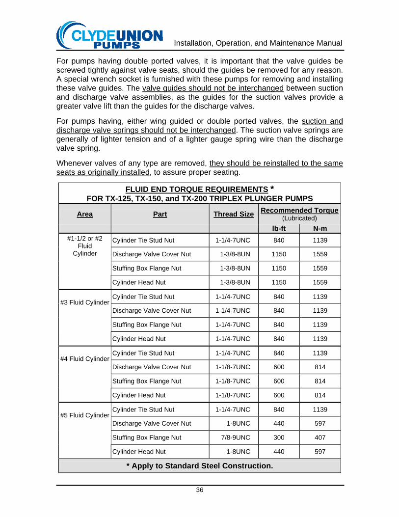
For pumps having double ported valves, it is important that the valve guides be screwed tightly against valve seats, should the guides be removed for any reason. A special wrench socket is furnished with these pumps for removing and installing these valve guides. The valve guides should not be interchanged between suction and discharge valve assemblies, as the guides for the suction valves provide a greater valve lift than the guides for the discharge valves. For pumps having, either wing guided or double ported valves, the suction and discharge valve springs should not be interchanged. The suction valve springs are generally of lighter tension and of a lighter gauge spring wire than the discharge valve spring. Whenever valves of any type are removed, they should be reinstalled to the same seats as originally installed, to assure proper seating.
FLUID END TORQUE REQUIREMENTS * FOR TX-125, TX-150, and TX-200 TRIPLEX PLUNGER PUMPS
Area Part Thread Size Recommended Torque (Lubricated)
lb-ft N-m Cylinder Tie Stud Nut 1-1/4-7UNC 840 1139
Discharge Valve Cover Nut 1-3/8-8UN 1150 1559
Stuffing Box Flange Nut 1-3/8-8UN 1150 1559
#1-1/2 or #2 Fluid
Cylinder Cylinder Head Nut 1-3/8-8UN 1150 1559
Cylinder Tie Stud Nut 1-1/4-7UNC 840 1139
Discharge Valve Cover Nut 1-1/4-7UNC 840 1139
Stuffing Box Flange Nut 1-1/4-7UNC 840 1139
#3 Fluid Cylinder
Cylinder Head Nut 1-1/4-7UNC 840 1139
Cylinder Tie Stud Nut 1-1/4-7UNC 840 1139
Discharge Valve Cover Nut 1-1/8-7UNC 600 814
Stuffing Box Flange Nut 1-1/8-7UNC 600 814
#4 Fluid Cylinder
Cylinder Head Nut 1-1/8-7UNC 600 814
Cylinder Tie Stud Nut 1-1/4-7UNC 840 1139
Discharge Valve Cover Nut 1-8UNC 440 597
Stuffing Box Flange Nut 7/8-9UNC 300 407
#5 Fluid Cylinder
Cylinder Head Nut 1-8UNC 440 597
* Apply to Standard Steel Construction.
Installation, Operation, and Maintenance Manual
37
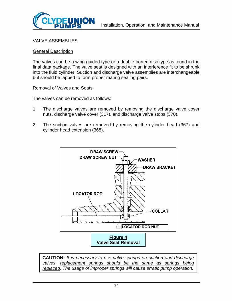
VALVE ASSEMBLIES General Description The valves can be a wing-guided type or a double-ported disc type as found in the final data package. The valve seat is designed with an interference fit to be shrunk into the fluid cylinder. Suction and discharge valve assemblies are interchangeable but should be lapped to form proper mating sealing pairs. Removal of Valves and Seats The valves can be removed as follows: 1. The discharge valves are removed by removing the discharge valve cover
nuts, discharge valve cover (317), and discharge valve stops (370). 2. The suction valves are removed by removing the cylinder head (367) and
cylinder head extension (368).
LOCATOR ROD NUT
Figure 4 Valve Seat Removal
CAUTION: It is necessary to use valve springs on suction and discharge valves, replacement springs should be the same as springs being replaced. The usage of improper springs will cause erratic pump operation.
Installation, Operation, and Maintenance Manual
38
3. Should it become necessary to remove valve seats, they can be removed
using a puller device consisting of a threaded rod, a collar, washers, nut, and a draw bracket. To remove the discharge valve seats, install the threaded rod into the collar through the discharge seat, place the draw bracket over the top of fluid cylinder, and threaded rod. Start the draw screw nut and thread it down to the draw bracket. Tightening this nut will apply tension to the draw screw and remove the valve seat from the fluid cylinder (see Figure 4). Follow the same procedure for the suction valve seats except as the seats are pulled loose they are removed through the cylinder bore.
Inspection of Valve Parts All valve parts should be inspected for wear and damage. Excessively worn or eroded valves, valve seats, springs, and valve stops should be replaced. Refinishing Valves and Seats Seating surfaces of valves and seats will occasionally require refinishing; the frequency depends on operating conditions and the liquid being pumped. Abrasives or other foreign matter in the liquid will shorten valve life. If a scratch, groove, or eroded area extends across the seating surface, the surfaces must be refinished prior to reassembly. Refinishing is done by lapping each value to the corresponding seat until a uniform seating surface is obtained. For best results start with a coarse compound and use a fine compound for final finishing. Under normal operating conditions, very little valve maintenance is required. Installation of Valve Seats Valve seats are a tapered wall interference fit and can be installed as follows: 1. After cleaning all components and the machined bores in fluid cylinder, make
sure they are free of burrs and other contamination. Shrink valve seats in dry ice (CO2) prior to assembly. Do not use liquid Nitrogen, as it is too cold. The valve seats can be installed by carefully placing it into seat bore and placing a flat and smooth steel plate of suitable size that has no burrs over the top of the valve seat and rapping it firmly with a hammer or bar.
NOTE: Use a piece of gasket material between seat and plate to prevent damage to disc type seats. Seats must be driven until flange of seat bottoms on cylinder.
2. The discharge valves (321), springs (335), valve stops (370), and covers
(317), can now be installed.
NOTE: New gaskets should be installed each time cylinder covers have been loosened and removed.
Installation, Operation, and Maintenance Manual
39
POWER END
NOTE: Refer to the specific drawings supplied in the final data package when using the following Assembly / Disassembly procedure. The number in parentheses after certain steps refer to component parts as identified on the drawings. Procedure for Dismantling TX-125 Power Frames Using Sectional Drawings and Parts Lists PX-410-1, PX-410-2, and PX-410-3 as Reference In order to completely dismantle power frame (100), the coupling or sheave must be removed from the pinion shaft. The plungers (353) will have to be removed. This can be done by removing the cylinder head (367) and the cylinder head extension (368). Now unscrew the plunger coupling nut (125) and remove the plunger coupling split collars (126). The split collars are numbered in pairs and must be replaced in the same location when reassembling the pump. The plungers may now be removed through the front of the cylinder (300). Proceed to dismantle power frame in this order: 1. Remove crosshead stub deflectors (123), crosshead stub seal caps (141),
and crankcase cover (154).
2. Remove crankshaft frame cap - inboard (133) and crankshaft end cap - inboard (140).
3. Remove thrust bearing nut and crankshaft frame cap - outboard (132). Keep
crankshaft frame cap shims intact so they can be assembled in the same position.
4. Remove oil pump chain (636). Remove thrust bearing assembly (145), (144),
(139), (143), and (142).
5. Disconnect oil lines from crankshaft bearing caps (109).
6. Disconnect connecting rods (112), push rods, and crosshead assembly as far forward as possible. Keep the connecting rod bearings (116) and the connecting rod shims (115) together so they can be assembled in the same position if they are reused. Rods and caps are stamped in pairs 1-2-3, etc.
WARNING: Before beginning the disassembly or assemblies of any components, make sure the power to the motor is turned off and locked in the off position.
Installation, Operation, and Maintenance Manual
40
7. Block up under crankshaft (103) to keep it from rolling out when crankshaft
bearing caps (109) are removed.
8. Remove crankshaft bearing caps (109). Crankshaft (103) can be rolled out on blocks or picked up with a chain fall. Care should be taken not to damage the crankshaft bearing cap studs and they should be removed before removing crankshaft as a safety precaution. The main gear (128) is a press fit on the crankshaft and if the gear is being replaced it may be removed with a press, gear puller, or heat. If the crankshaft bearings (107) are being replaced, they can be removed with a press or apply heat and pry off.
9. To remove pinion gear and shaft (129) the driver or power frame must be
moved to allow clearance for pulling. Next remove the pinion shaft frame cap (137) and pull out the pinion gear and shaft and pinion shaft bearing (149) assembly. The pinion shaft bearings are a press fit on the pinion shaft and can be removed with a press or heat. When installing the pinion assembly allow .005-.008 inches end play.
10. The connecting rod (112) and crosshead assembly (117, 119, 120, 121, 122,
643, and 644) may be removed from the back of the frame. If the crosshead assembly is to be reused it must be replaced in the same location.
11. The crosshead pin (119) is held in the crosshead with two set screws.
Remove the set screws (643) and tap out the pin. Crosshead pin bearing (120) is a press fit in the connecting rod. When replacing be sure and line up the hole in the crosshead pin bearing (120) with the hole in the connecting rod (112) and crosshead pin (119) and lock in place.
12. The crosshead stub (122) is a press fit in the crosshead and doweled. The following are the clearances when all parts are new:
Part Location
When Parts Are New
Replace part (or Adjust) When Clearance Exceeds:
Inch mm Inch Mm
Crosshead (117) in Power Frame (100) 0.007 to 0.009 0.18 to 0.23 0.011 0.28
Crosshead pin (119) in crosshead pin bearing (120) 0.0030 to 0.0037 0.07 to 0.09 0.005 0.12
Crosshead pin (119) in crosshead 0.0008 to 0.0014 0.02 to 0.04 0.002 0.05
Connecting rod bearing (116) over crankshaft (103) 0.005 to 0.007 0.12 to 0.18 0.012 0.30
Reassemble power frame in reverse order. It is a good practice to install new oil seals (632), (633), and (631) as well as new gaskets.
Installation, Operation, and Maintenance Manual
41
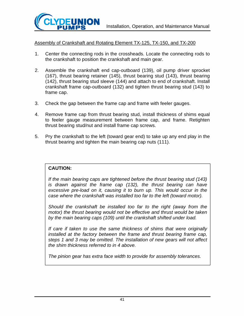
Assembly of Crankshaft and Rotating Element TX-125, TX-150, and TX-200 1. Center the connecting rods in the crossheads. Locate the connecting rods to
the crankshaft to position the crankshaft and main gear.
2. Assemble the crankshaft end cap-outboard (139), oil pump driver sprocket (167), thrust bearing retainer (145), thrust bearing stud (143), thrust bearing (142), thrust bearing stud sleeve (144) and attach to end of crankshaft. Install crankshaft frame cap-outboard (132) and tighten thrust bearing stud (143) to frame cap.
3. Check the gap between the frame cap and frame with feeler gauges.
4. Remove frame cap from thrust bearing stud, install thickness of shims equal
to feeler gauge measurement between frame cap, and frame. Retighten thrust bearing stud/nut and install frame cap screws.
5. Pry the crankshaft to the left (toward gear end) to take up any end play in the
thrust bearing and tighten the main bearing cap nuts (111).
CAUTION: If the main bearing caps are tightened before the thrust bearing stud (143) is drawn against the frame cap (132), the thrust bearing can have excessive pre-load on it, causing it to burn up. This would occur in the case where the crankshaft was installed too far to the left (toward motor). Should the crankshaft be installed too far to the right (away from the motor) the thrust bearing would not be effective and thrust would be taken by the main bearing caps (109) until the crankshaft shifted under load. If care if taken to use the same thickness of shims that were originally installed at the factory between the frame and thrust bearing frame cap, steps 1 and 3 may be omitted. The installation of new gears will not affect the shim thickness referred to in 4 above. The pinion gear has extra face width to provide for assembly tolerances.
Installation, Operation, and Maintenance Manual
42
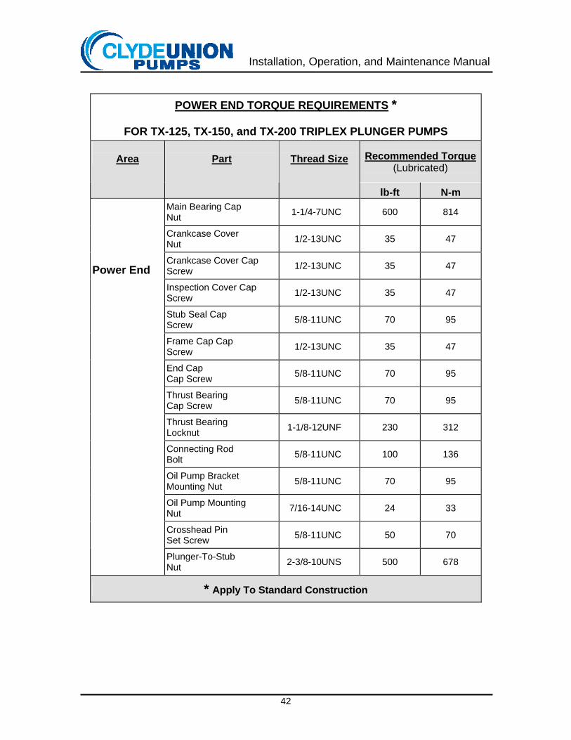
POWER END TORQUE REQUIREMENTS *
FOR TX-125, TX-150, and TX-200 TRIPLEX PLUNGER PUMPS
Recommended Torque (Lubricated)
Area
Part
Thread Size
lb-ft N-m Main Bearing Cap Nut 1-1/4-7UNC 600 814
Crankcase Cover Nut 1/2-13UNC 35 47
Crankcase Cover Cap Screw 1/2-13UNC 35 47
Inspection Cover Cap Screw 1/2-13UNC 35 47
Stub Seal Cap Screw 5/8-11UNC 70 95
Frame Cap Cap Screw 1/2-13UNC 35 47
End Cap Cap Screw 5/8-11UNC 70 95
Thrust Bearing Cap Screw 5/8-11UNC 70 95
Thrust Bearing Locknut 1-1/8-12UNF 230 312
Connecting Rod Bolt 5/8-11UNC 100 136
Oil Pump Bracket Mounting Nut 5/8-11UNC 70 95
Oil Pump Mounting Nut 7/16-14UNC 24 33
Crosshead Pin Set Screw 5/8-11UNC 50 70
Power End
Plunger-To-Stub Nut 2-3/8-10UNS 500 678
* Apply To Standard Construction

Installation, Operation, and Maintenance Manual
Index of Order Specific Drawings
(If applicable)

Installation, Operation, and Maintenance Manual
This page intentionally left
blank
Installation, Operation, and Maintenance Manual
Warranty
Company warrants that on the date of shipment from Company’s facility the Goods are of the kind and quality described herein and are free of non-conformities in design, workmanship and material and meet the specifications set forth on the Purchase Order accepted by Company. Buyer's exclusive remedy for nonconformity in any item of the Goods shall be the repair or the replacement (at Company's option) of the item and any affected part of the Goods. Company’s obligation to repair or replace shall be in effect for a period of one (1) year from initial operation of the Goods but not more than eighteen (18) months from Company’s delivery of the Goods, provided Buyer has sent written notice within that period of time, or within thirty (30) days after the end of the applicable warranty period to Company that the Goods do not conform to the above warranty. Repaired and replacement parts shall be warranted for the remainder of the original period of notification set forth above, but in no event less than 12 months from repair or replacement. At its expense, Buyer shall remove and ship to Company any such nonconforming items and shall reinstall the repaired or replaced parts. Buyer shall grant Company access to the Goods at all reasonable times in order for Company to determine any nonconformity in the Goods. Company shall have the right of disposal of items replaced by it. If Company is unable or unwilling to repair or replace, or if repair or replacement does not remedy the nonconformity, Company and Buyer shall negotiate an equitable adjustment in the Purchase Order price. This warranty shall not apply in the event of defects caused by: (i) physical abuse of the Goods or any component, or acts of vandalism by any persons other than Company, its employees, agents, or subcontractors; (ii) alterations, modifications, additions, or repairs made during the applicable warranty period by anyone other than Company, its employees, agents or subcontractors; (iii) accidents or damage resulting from fire, water, wind, hail, lightning, electrical surge or failure, earthquake, theft or similar causes not caused or contributed to by the sole negligence of Company or its employees, agents, or subcontractors; or (iv) damage as a result of corrosion or other damage caused by Buyer’s failure to protect the Goods in accordance with Company’s written instructions and warnings. THE FOREGOING WARRANTIES ARE THE SOLE WARRANTIES PROVIDED BY COMPANY FOR THE GOODS AND ARE IN LIEU OF ALL OTHER WARRANTIES, EXPRESS OR IMPLIED, ALL OF WHICH ARE HEREBY DISCLAIMED AND EXCLUDED BY COMPANY, INCLUDING, WITHOUT LIMITATION, ANY WARRANTY OF MERCHANTABILITY OR FITNESS FOR A PARTICULAR PURPOSE OR USE. BUYER AGREES THAT IT’S SOLE AND EXCLUSIVE REMEDY AGAINST COMPANY WILL BE LIMITED TO THE REPAIR AND REPLACEMENT OF NONCONFORMING OR DEFECTIVE GOODS, PROVIDED COMPANY IS PROMPTLY NOTIFIED IN WRITING OF ANY DEFECT.

Installation, Operation, and Maintenance Manual
Maintenance Record
Date Work Performed
Installation, Operation, and Maintenance Manual
To maintain peak pump performance…
Insist on genuine Clyde Union, Inc. parts
Swift service from facilities in UNITED STATES Midwest Service Center Clyde Union, Inc. 4600 West Dickman Road Battle Creek, MI 49037 269-966-4600 Phone 269-966-4644 Fax Southeast Service Center Clyde Union, Inc. 12742 Ronaldson Road Baton Rouge, LA 70807 225-775-2660 Phone 225-774-7555 Fax Southwest Service Center Clyde Union, Inc. 10723 Rockley Road Houston, TX 77099 281-933-2900 Phone 281-933-6434 Fax Western Coast Service Center Clyde Union, Inc. 9838 Firestone Blvd. Downey, CA 90241 562-622-2380 Phone 562-622-2385 Fax East Coast Service Center Rotating Technology Services, Inc. An Authorized Field Service Representative of Clyde Union, Inc. 177 Mikron Road Bethlehem, PA 18020 610-746-4571 Phone 610-746-5907 Fax
CANADA Burlington Service Center Clyde Union Canada Limited 4211 Mainway Drive Burlington, Ontario L7L 5N9 Canada 905-315-3800 Phone 905-336-2693 Fax Calgary Service Center Clyde Union Canada Limited 3525 62nd Avenue SE Calgary, Alberta, T2C 1P5 Canada 403-236-8725 Phone 403-236-7224 Fax UNITED KINGDOM Clyde Union DB Limited Green Road Penistone, Sheffield, UK S36 6BJ +44 (0) 1226 763 311 Phone +44 (0) 1226 766 535 Fax FRANCE Clyde Union S.A.S. 39, Avenue du Pont de Tasset B.P. 435-74020 Annecy Cedex France +33 (0) 4 50 05 5600 Phone +33 (0) 4 50 05 5880 Fax SERVICE SUPPORT 24/7: +1 (269) 966-4664 US – 1-800-877-PUMP UK - +44 (0) 1 226 222 200 CANADA 1-905-315-3800 EU - +33 (0) 4 50 05 5600
For more information, visit our website at: http://www.clydeunion.com
Related Documents