University fOUNDED t1 // ' i> TWO-WAY FLEXURAL BEHAVIOR OF STEEL-DtCK-REINrORCED CONCRETE ^\.ABS EY CHAr^LES R. KUBIC Ll. CEC USN ritz Engineering Laboratory lAY 1978 Approved for Public Release; Distribution unlimited.

Welcome message from author
This document is posted to help you gain knowledge. Please leave a comment to let me know what you think about it! Share it to your friends and learn new things together.
Transcript

University
fOUNDED t1 //'
i>
TWO-WAY FLEXURAL BEHAVIOR OF
STEEL-DtCK-REINrORCED
CONCRETE ^\.ABS
EY
CHAr^LES R. KUBIC
Ll. CEC USN
ritz
Engineering
Laboratory
lAY 1978
Approved for Public Release;Distribution unlimited.


REPORT DOCUMENTATION PAGE KF,AD INSTRUrxirxNSBEFORE COKPLETINf. FORM
1 PIEPORT NUMBCN 2. GOVT ACCESSION NO. 1 RECIPlEMT'S C AT ALOG NUMOtR
4 TITLE (mnd Subllltm)
Two-way Flexural Behavior of Steel-DeckReinforced Concrete Slabs
5 TYPE OF REPORT ft PERIOD COVERED
Thesis• . PERFORMING ORG. REPORT NUMBER
7. AuTHORr«J
Charles R. KUBIC
• CONTRACT OR GRANT NUMBERft;
9 PERFORMINO OnOANlZATION NAME ANO AOONEIi
Lehigh UniversityBethlehem, PA
10. PROGRAM ELEMENT, PROJECT. TASKAREA ft WORK UNIT NUMBERS
n, CONTROLLING OFFICE NAME AND ADDRESS
NAVPGSCOL CODE 031
12. REPORT DATE
MAY 7813 NUMBER OF PAGES
62t4 MONITORING AGENCY NAME * ADORESSC" (f<//*ranr from Controllint Ollleu) 18. SECURITY CLASS, (ol thf tmportj
UNCLASSiSa. DECLASSIFI cation/ DOWN GRADING
SCHEDULE
16. DISTRIBUTION STATEMENT (ol thli Ruporl)
^- Approved for public release; distribution unlimited.
17. DISTRIBUTION STATEMENT (et (ft* abtttmet •rlurmd in Block 30, II dlllarmM /reoi R»port)
16. SUPPLEMENTARY NOTES
19. KEY WORDS (Contlnuu on r*r«r*a aldu II nocofmry and Idontlty by block nu>ib«0
Flexural Behavior; Steel Deck Reinforced; Concrete Slabs
20. ABSTRACT (Conllnuo on rmvruo mido II nocmtmarr and Idmntltr by block nunbarj
DO 1 JAN 71 1473 EDITION OF 1 NOV 81 IS CiliOLETB
(Pape 1) S/N 0102-014- 6601 I
SECURITY CLASSIFICATION OF THIS PAGE (Whon Dmim tntorod]
.*


Approved for Public Release;
Distribution unlimited
TWO-WAY FLEXURAL BEHAVIOROF
STEEL-DECK-REINFORCED CONCRETE SLABS
By
Charles R. KubicLT, CEC, USN
This research was carried out in partialfulfillment of the requirements for the degreeof Master of Science in Civil Engineering.
Department of Civil Engineering
Fritz Engineering LaboratoryLehigh University
Bethlehem, Pennsylvania
May 1973

i \ .\

ACKNOWLEDGEMENTS
This research was conducted at Fritz Engineering Laboratory,
Lehigh University, Bethlehem, Pa. and was carried out in conjunction
with postgraduate study in Structural Engineering sponsored by the
Chief of Naval Operations. Dr. Lynn S, Beedle is Director of Fritz
Engineering Laboratory and Dr. David A. VanHorn is Chairman of the
Department of Civil Engineering.
Appreciation is expressed to Ms . S. Matlock who carefully
typed this report, to Mr. J. M. Cera who skillfully prepared the
illustrations, and to Mr. T. Wenk who initiated preliminary studies
on this topic in May 1977. Finally, the author is indebted to Dr.
J. Hartley Daniels, who served as his advisor and who consistently
provided learned guidance throughout the preparation of this report.
11

TABLE OF CONTENTS
Page
ABSTRACT 1
1. INTRODUCTION 3
1.1 Current Practice 4
1.2 Current Research 6
1.3 Purpose and Scope 8
1.4 Assumptions 9
2. FINITE ELEMENT MODEL DEVELOPMENT 10
2.1 Orthotropic Plate Theory 11
2.2 Alternative Models 15
2.3 Model Parameters 16
3. ORTHOTROPIC PLATE ANALYSIS 19
3.1 Governing Equations 19
3.2 Summary of Results 21
4. MODEL VALIDATION 22
4.1 Convergence Study 22
4.2 Comparison with Alternate Model 23
4.3 Comparison with Theoretical Results 24
4.4 Comparison with Test Results 25
5. PARAMETRIC STUDY 27
5.1 Purpose and Scope 27
5.2 Results 28
6. CONCLUSIONS AND RECOMMENDATIONS 31
7
.
NOMENCLATURE 35
8. TABLES 38
9. FIGURES 42
10. APPENDICES 55
11. REFERENCES 62
iii


LIST OF TABLES
TABLE PAGE
1 Section and Material Properties 39
2 Orthotropic Plate Constants 40
3 Comparison of Theoretical and Finite Element Model 41
Results
IV


LIST OF FIGURES
FIGURE PAGE
1 Alternate Conventional Floor Systems 43
2 Typical Cross Section 4A
3 Model Development 45
4 Structurally Orthotropic Finite Element Model 46
5 Typical Finite Element Model Discretization 47
6 Convergence Study-Deflections 48
7 Convergence Study-Moments 49
8 Comparison of Model and Test Results (One-Way Bending) 50
9 Comparison of Model and Test Results (Two-Way Bending) 51
10 Aspect Ratio Parametric Study 52
11 Deflection Coefficient vs. Aspect Ratio 53
12 Moment Coefficients vs. Aspect Ratio 54


LIST OF APPENDICES
APPENDIX PAGE
A Computation of Model Parameters 56
B Computation of Theoretical Deflections and Moments 58
C Optimum Aspect Ratio 60
VI

ABSTRACT
The two-way flexural behavior of steel-deck-reinforced con-
crete slabs is exaonined and the feasibility of considering two-way
action in the design of such slabs is discussed. An elastically
orthotropic finite element model with uniform thickness is developed
which simulates the behavior of a structurally orthotropic steel-
depk-reinforced concrete slab. The model development is based upon
appropriate modifications to the elasticity constants and to the
thickness of the plate bending element included in the SAP IV
finite element program. The linear, elastic, uncracked behavior of
a typical steel-deck-reinforced concrete slab is examined utilizing
the elastically orthotropic model; and, the resulting deflections
and moments are observed to conform with theoretical results and
with a more sophisticated structurally orthotropic model. The
elastically orthotropic finite element model is also correlated with
previously tested steel-deck-reinforced concrete slabs and the
results predicted by a finite element analysis are found to conform
with the actual test results in the uncracked region.
The results of a limited parametric study, which considers
the relative effects of aspect ratio, rib span direction, and edge
support conditions on two-way flexural behavior, are presented.
Deflections and bending moments for two-way flexural action are
compared with similar values for one-way bending and an expression
is proposed for computing an optimum aspect ratio for a given ortho-
tropic steel-deck-reinforced concrete slab.


Although the analysis in this report is based upon several simpli-
fying assumptions, the two-way design of steel-deck-reinforced concrete
slabs is nevertheless found to be a feasible and potentially advantageous
concept
.


1. INTRODUCTION
Cold-formed steel decking, as shown in Fig. 1(a), is extensively
utilized in the construction of floor systems for steel framed buildings
and often serves the dual function of providing forming for concrete
during slab construction and positive reinforcement for the floor slab
under service conditions. In addition to simplifying forming and
reducing reinforcing steel, such a floor system also provides a safe
working platform during construction; can easily accommodate pre-
engineered raceways for electrical, communications, and air distribution
systems; and, upon completion, presents a finished underside with no
visible cracks. However, steel-deck-reinforced concrete slab systems
are generally heavier and thicker than alternate floor systems, such as
flat plate concrete slabs (Fig. 1(b)), and despite numerous advantages,
their general application is often limited by both technical and
economic considerations. Such limitations are directly linked to the
method of one-way flexural analysis utilized in the conventional
design of steel-deck-reinforced concrete floor systems. Reinforced
concrete floor slabs, on the other hand, are routinely analyzed as
two-way flexural systems to achieve overall economy of design. The
two-way flexural behavior of steel-deck-reinforced concrete slabs will
be examined in this report and the feasibility of designing such slabs
to take advantage of two-way flexural action will be discussed.

1. L Current Practice
Although steel deck floor systems generally result in a
thicker "floor sandwich" than flat plate concrete floor systems,
they are usually much easier to install, and, in particular, they
provide additional flexibility for the installation of under-floor
utility systems. Consequently, steel-deck-reinforced concrete floor
systems can often be economically utilized in commerical facilities,
office buildings, or hospitals. However, they are less economical
for residential facilities such as apartment buildings, hotels, or
dormitories which have fixed interior partitions and do not depend
upon the floor system for installation of utility lines. The
overall cost of high-rise buildings is particularly sensitive to the
overall thickness of the "floor sandwich" and facilities which do
not require mechanized or electrified floor systems can often be
more economically constructed utilizing precast concrete floor
panels or flat plate concrete slabs.
Steel decking is often utilized strictly as stay-in-place
forming material and alternate reinforcing is provided for the
concrete slab. Steel-deck reinforced concrete floor slabs, however,
are composite structural systems which achieve satisfactory composite
action by developing positive interlocking between the steel deck
and the concrete. Steel decks are currently manufactured which
utilize various patterns of embossments to mechanically transfer
horizontal shear and to prevent vertical separation between the deck
and the concrete. The load carrying capacities of such composite

sections are normally established through proprietary performance
tests conducted by the various manufacturers, and design is general-
ly based upon one-way bending of simple span slabs. However, a
flexural mode of failure is rarely achieved for typical sections
spanning moderate (6-12 ft) lengths, and design is often governed by
other criteria such as shear-bond failure, allowable deck stresses
during construction, or acceptable deflections during construction or
service loading. Additionally, the thickness of steel deck floor
systems may also be governed by required fire resistance ratings.
The various steel-deck manufacturers generally recommend maximum
one-way spans in the range of 15 feet for steel-deck-reinforced con-
crete slabs. However, spans of 6-10 feet are more commonly utilized
so as to obviate the need for expensive temporary shoring and to
minimize the depth of supporting members. As mentioned earlier, a
steel deck floor system, with its associated beam/joist framing system
will generally result in a relatively thicker "floor sandwich" than a
concrete flat plate or pre-cast floor system. However, in commercial
facilities requiring extensive underfloor utility systems and mechanized
or electrified floors, cellular steel deck, in particular, can provide an
alternative, economically feasible floor system when constructed com-
positely with the concrete slab.

1.2 Current Research
Extensive research on steel-deck-reinforced concrete slabs
subjected to one-way bending has been conducted at Iowa State Univer-
sity by Ekberg, Schuster, and Porter. » ' > -' Test results have
indicated that the shear-bond failure mode is predominant over the
flexural failure mode, particularly in shorter spans; and, it has
therefore been recommended that such a failure mode should be a
primary design consideration. Shear-bond failure was classified as
a brittle type of failure characterized by the formation of an approx-
imately diagonal crack (resulting from excessive principal tension
stresses) which resulted in end slip and a loss of bond between the
steel deck and the concrete. It was observed that shear-bond capacity
increased with an increase in depth, a decrease in shear span, or an
increase in the compressive strength of concrete. An ultimate strength
design procedure, which incorporates a specified testing program to
establish shear-bond capacity, was proposed for steel-deck reinforced
concrete slabs subjected to one-way bending.
( c.\
Limited research has also been conducted by Porter and Ekberg
on the behavior of steel-deck-reinforced concrete slabs subjected to
two-way bending. Five simply supported slabs (12 ft x 16 ft) with
varying section properties and with ribs spanning 12 feet were sub-
jected to four concentrated loads near the center span region, and
failure mode, cracking pattern and end reactions were observed. All
five slabs failed ultimately by a shear-bond type of failure, character-
ized by horizontal end slippage accompanied by the development of


diagonal cracks. End slippage was similar to that experienced in
one-way slab tests, however no end slip was observed along the edges
transverse to the span of the steel deck ribs.
Although none of the five slabs failed by extensive yielding of
the steel deck, some limited yielding of the steel deck did occur in
the central regions near the concentrated load points. Measured end
reactions indicated that about 787o of the total applied load during the
initial load applications was transmitted in the strong direction.
However, near ultimate load, one-way bending was predominate and 97%
of the total force was carried in the strong direction. Maximum edge
reactions in the weak direction usually occurred when the live load
was 507c, of the ultimate load or at approximately the working load level.
Porter recommended that analysis of steel-deck-reinforced
concrete slabs subjected to two-way bending consider only the section
above the deck corrugations as effective for transverse flexural action.
Moreover, he suggested that only supplementary steel in the transverse
direction be considered for computing flexural capacity and that any
contribution from the steel deck should be neglected. Porter observed
that a slab which had 6x12 D0xD4 WWF placed directly on top of the
steel decking had a higher ultimate load than slabs without such rein-
forcement. It is quite possible that supplementary transverse rein-
forcement increases both shear bond and transverse flexural capacity
and thus increases the overal 1 ultimate capacity of a two-way steel-
deck-reinforced concrete slab. Porter's results are discussed further
in Art. 4.4.


1.3 Purpose and Scope
The desired failure mode of any reinforced concrete structural
system is a flexural failure of an under-reinforced cross section.
Steel-deck-reinforced concrete slab sections commonly utilized in
building construction will predominantly experience shear bond failure
or excessive deflections prior to reaching their ultimate flexural
capacity. Consequently, such sections actually fail prematurely, thus
lowering allowable loadings or reducing allowable span lengths. If all
factors which precipitate failure prior to the achievement of ultimate
flexural capacity could be controlled and a flexural failure realized,
steel decking could be more efficiently utilized as reinforcement for
concrete floor slabs. Moreover, the relative economic benefits of
steel-deck-reinforced concrete floor slabs could be significantly
improved if such slabs were designed as two-way flexural systems.
An elastically orthotropic finite element model with constant
thickness will be developed to facilitate the analysis of structurally
orthotropic steel-deck-reinforced concrete slabs. The elastically
orthotropic model will be compared with theoretical results, with a
more refined structurally orthotropic finite element model, and with
one-way and two-way test results as compiled by Ekberg, Schuster, and
Porter. ' Once validated, the finite element model will be utilized
to conduct a limited parametric study in which the relative effects
of aspect ratio, rib span direction, and edge support condition will be
examined. The general feasibility of designing steel-deck-reinforced
concrete slabs as two-way flexural systems will be discussed;
8


however, it is recognized that much more intensive analytical studies
as well as extensive laboratory tests are necessary to confirm the
findings of this preliminary research. In effect, this report serves
as a "ground level" feasibility study on the two-way flexural behavior
of steel-deck-reinforced concrete slabs.
1.4 Assumptions
The limited scope of this investigation is unavoidably con-
strained by several basic assumptions. Such assumptions will
necessitate careful interpretation of the findings of this study,
but will not invalidate their basic significance. In general, all
analyses have been performed on the basis of linear elastic behavior
of an uncracked cross section. More specifically it has been
assumed that:
a. Additional transverse and longitudinal reinforcement will be
added to the cross section as required to maintain the same
relative uncracked stiffnesses subsequent to cracking as well
as to satisfactorily resist two-way bending moments.
b. Shear bond failure can be prevented prior to flexural failure
by modifying the steel deck profile (embossments), by adding
specialized shear connectors, by applying special adhesive
coatings, or by some other acceptable technique.
c. Excessive deflections and/or construction loadings can be
economically controlled by improved shoring techniques, by
two-way flexural action of the steel deck alone, by pre-cast
construction or by other suitable techniques.


2. FINITE ELEMENT MODEL DEVELOPMENT
The SAP IV finite element computer program provides
several alternative methods for modeling a steel-deck-reinforced
concrete slab subjected to distributed or concentrated loads perpen-
dicular to the plane in which it lies. The plate bending element provides
the most convenient and efficient method for analyzing isotropic
plate bending problems and can readily be adapted to elastically
orthotropic problems by properly populating the plane stress material
elasticity matrix given as follows:
fnXX
yy
xs
C C CXX xy xs
C C Cxy yy ys
C C Gxs ys xy
XX
yyi
xy
2.1
where.XX
xy
cyy
E
1-v^
vE
l-^P
C =« C =xs ys
xy 2(l+v)
for the case of isotropic plate bending.
2.2
In isotropic or elastically orthotropic plate bending problems,
the finite element is given a specified uniform thickness and appro-
priate rigidity factors are computed utilizing the specified elasticity
constants. However, a structurally orthotropic steel-deck reinforced
concrete slab, with typical cross section as shown in Fig. 1(a)(7)
10


can not be modeled as conveniently using plate bending elements. On
the other hand, however, alternative models utilizing more sophisti-
cated elements become more complex as well as exponentially more
expensive. Consequently, elasticity parameters were developed which
permitted the modeling of a structurally orthotropic plate as an
elastically orthotropic plate with an equivalent uniform thickness,
and analytical results were compared with results gene rated by a more
sophisticated finite element model as well as with theoretical and
test results.
2.1 Orthotropic Plate Theory
/ONFor engineering applications, an orthotropic plate is defined^ '
as a plate having different bending stiffnesses (D =» EI) in two ortho-
gonal directions X and Y in the plane of the plate. The variation in
bending stiffness may result either from different moduli of elasti-
city E and E in two orthogonal directions, as in the case of natural-X y
ly or elastically orthotropic plates, or from different moments of
inertia I and I per unit width, as in the case of technically orX y ^
structurally orthotropic plates.
Ruber's general differential equation for the bending of an
/ONorthotropic plate is expressed as follows:
B^w ^ 5^w S'^w . .
°x B^ •" 2H ^p^ + D^ = q(^.y) 2.3
where 2H=Dv+Dv+4D 2.4X y y X xy
The quantities D and D are termed the flexural rigidities of theX y
plate while D represents the torsional rigidity of the plate. Thexy
^^


value of 2H from Eq. 2.4 is termed the effective torsional rigidity
of the orthotropic plate.
In general terms, Eq. 2.3 relates the plate's deflection
surface w(x,y) to a given load distribution q(x,y). To apply the
solution of Eq. 2.3 to engineering problems, it is necessary to
evaluate proper values for the constants D , D , D , v , and v .^ ^ x' y' xy x' y
For an elastically orthotropic slab of uniform thickness (h), the
constants are defined as follows:
D
E h°
X 12(l-v V )X y
E h—I.
3
y 12(l-v V )X y
2.5
G h^
D - -^xy 12
E V = E V (from Betti's reciprocal theorem)X y y x
The values of the moduli of elasticity E and E and the correspondingX y
Poisson's constants v and v are usually known for a given elasticallyX y
orthotropic material. However, the value of the shear modulus G , which
is encountered in the expression for the torsional rigidity D , and whichxy
consequently also influences the effective torsional rigidity H, is
usually unknown.
An approximate value of the effective torsional rigidity can
/ONbe theoretically expressed by the equation.
H = /WW 2.6X y
12


if an analogy is drawn with the expression for the twisting moment
of an isotropic plate utilizing D = /D D and v = /v v as repre-xy xysentive "middle values" of the bending rigidity and Poisson' s con-
stant. This approximation is valid only if the orthotropic plate
satisfies the following conditions:
a. uniform thickness
b. purely elastic deformations
c. relatively small deformations.
Because such assumptions are not actually satisfied in reality,
particularly for a structurally orthotropic plate, it has been
/ONsuggested that the value of H should be reduced by a coefficient
of torsional rigidity Yj so that
H = Y ,/d"^ 2.7x y
where Y < 1 and normally varies between 0.3 and 0.5.
A proper theoretical expression for G is particularly
important when modeling a structurally orthotropic plate as an
equivalent elastically orthotropic plate for a finite element analysis
(9)Szilard suggests that G for an orthotropic material can be
xy '^
approximately expressed as follows:
/EE
xy 2 ( IV V V )X y
or if E « E « EX y
^xy ^ 2(l+/v^r)^'^
X y
13

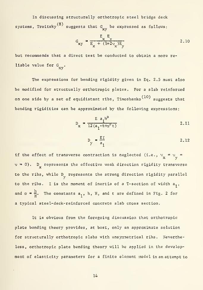
In discussing structurally orthotropic steel bridge deck
(8)systems, Troitsky suggests that G be expressed as follows:
xy
E En = 2L_Ixy E + (H-2v )E
X x y
2.10
but recommends that a direct test be conducted to obtain a more re-
liable value for Gxy
The expressions for bending rigidity given in Eq. 2.5 must also
be modified for structually orthotropic plates. For a slab reinforced
on one side by a set of equidistant ribs, Timoshenko suggests that
bending rigidities can be approximated by the following expressions:
E a h°
D ~ ToT m^TZT 2.11x 12(a -t+or t)
D =— 2.12y a^
if the effect of transverse contraction is neglected (i.e., v = v =X y
V = 0). D represents the effective weak direction rigidity transverse
to the ribs, while D represents the strong direction rigidity parallel
to the ribs. I is the moment of inertia of a T-section of width a ,
and a "^ —. The constants a , h, H, and t are defined in Fig. 2 forH 1
a typical steel-deck-reinforced concrete slab cross section.
It is obvious from the foregoing discussion that orthotropic
plate bending theory provides, at best, only an approximate solution
for structurally orthotropic slabs with unsymmetrical ribs. Neverthe-
less, orthotropic plate bending theory will be applied in the develop-
ment of elasticity parameters for a finite element model in an attempt to
14


provide a comparably accurate finite element solution for a structurally
orthotropic steel-deck-reinforced concrete slab.
2.2 Alternative Models
The finite element model was developed by considering the typical
cross section shown in Fig. 2 spanning a 16 ft x 16 ft panel with four
simply supported edges. A representative section of the actual struc-
turally orthotropic slab is illustrated in Fig. 3(a). The models shown
in Figs. 3(b) and (c) would provide lower and upper bound solutions for
two-way flexure of the slab. The uniform thickness of such a model
would facilitate finite element discretization, however, the effects
of the steel plate must necessarily be considered by utilizing an
equivalent uniform model thickness, based upon the cross section's
transformed moment of inertia. The actual results obtained from such
an analysis would be relatively insignificant despite the fact that
they would bound the correct solution.
Figure 4 illustrates a rather sophisticated finite element
discretization utilizing 8-node bricks to model the concrete, and
plate bending elements to model the steel deck. While such a model
should provide excellent results, its complexity and expense degrade
its usefulness for general application. A comparison between this
model and the elastically orthotropic model is presented in Art. 4.2.
Modeling the structurally orthotropic slab as an isotropic plate
supported by beams representing the ribs would provide still
15

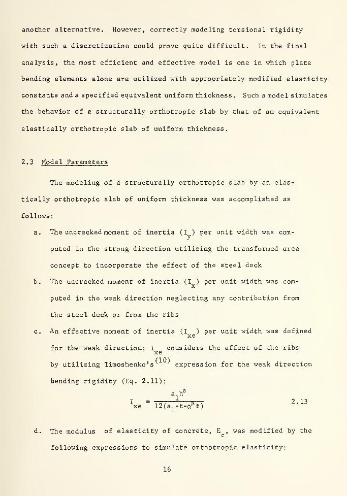
another alternative. However, correctly modeling torsional rigidity
with such a discretization could prove quite difficult. In the final
analysis, the most efficient and effective model is one in which plate
bending elements alone are utilized with appropriately modified elasticity
constants and a specified equivalent uniform thickness. Such a model simulates
the behavior of e structurally orthotropic slab by that of an equivalent
elastically orthotropic slab of uniform thickness.
2.3 Model Parameters
The modeling of a structurally orthotropic slab by an elas-
tically orthotropic slab of uniform thickness was accomplished as
follows:
a. The uncracked moment of inertia (I ) per unit width was com-
puted in the strong direction utilizing the transformed area
concept to incorporate the effect of the steel deck
b. The uncracked moment of inertia (I ) per unit width was com-
puted in the weak direction neglecting any contribution from
the steel deck or from the ribs
c. An effective moment of inertia (I ) per unit width was definedxe '^
for the weak direction; I considers the effect of the ribsxe
by utilizing Timoshenko's expression for the weak direction
bending rigidity (Eq. 2.11):
^xe " 12(a^-t-a"t)^-^^
d. The modulus of elasticity of concrete, E , was modified by the
following expressions to simulate orthotropic elasticity:
16


I
E = -f^ (E ) 2.14X I c
X
E = —^ (E ) 2 . 15y I c
xe
e. Poisson's ratio for concrete (v ) was modified as follows:c
I
V = -p (v ) 2.16X I c
y
I
V =» T^ (v ) 2.17y I c' xe
so as to maintain the equality vE =vE =vExy yx cc
f. Orthotropic elasticity constants were computed as follows
utilizing E , E , v and v :
X y X y
2.18aEX
'xx 1 - V VX y
Ey
'yy 1 - V VX y
/v V E EX y X y
'xy 1 - V VX y
E EX y
xy E + (1+2 V )EX X y
2.19
2.20
2.21
g. An equivalent uniform slab thickness was computed as follows:
t = Vl2 I 2.21e xe
17


In general terras, this modeling technique simulates structural
orthotropy by proportionately increasing the modulus of elasticity of
concrete to reflect effective moments of inertia in the strong and weak
direction, while incorporating an equivalent uniform thickness. This
technique does, however, possess one inconsistency in that the simulated
bending rigidity in the weak direction is relatively higher than would
be theoretically deduced. This results from the fact that both the
moment of inertia and the modulus of elasticity in the weak direction
are increased resulting in a relatively higher increase in rigidity
in the model's weak direction as compared to its strong direction. The
significance of this inconsistency is discussed later.
Troitsky's value for G (Eq. 2.10) was selected because ofxy
its general applicability to structurally orthotropic slabs and
because of the good correlation which it produced with both theoreti-
cal solutions and test results.
Uncracked section properties and material properties for the
typical section utilized in the model's development are listed in Table
1. The computation of model parameters is included in Appendix A, and
the final elastically orthotropic slab model is illustrated in Fig. 3(d)
18


3. ORTHOTROPIC PLATE ANALYSIS
For the case of a uniformly loaded, simply supported rectangular
orthotropic plate, Eq. 2.3 can be solved utilizing the Navier
method. This solution expresses the plate's deflection surface
in terms of a double trigonometric series:
1 - « « J raTTx . nrry16 q r-, r-i sin sm —rp
w ° ^ °
2, i—
^^^ t:^-:^ 1^ r 3.1^^^~ L L 7m* ^ ,2m2n2
m= IOC IOC mnl-5- D H g-rg- H + rTT D'1,3,5... n=l,3,5... \a x a^b^ b y/
Tabularized solutions are available for Eq. 3.1 for the particular case
of H = /D D . Although such a case is normally representative ofX y
elastically orthotropic plates, such as two-way reinforced concrete
slabs, it will nevertheless be applied to a structurally orthotropic
steel-deck-reinforced concrete slab utilizing the elasticity constants
computed for the finite element model parameters.
3.1 Governing Equations
For the case in which H = /D D , the deflection and theX y
bending moments at the center of an orthotropic plate can be expressed
by the following equations:
Ck' q b*
y
19


ih-hr'JT^K^MXX
yy X
. C /T". q
•^ XX y
where a, 0, , and 3„ are numerical coefficients given in Table 2 and
X
If the effect of transverse contraction is neglected Cxy
becomes equal to zero and Eqs . 2.11 and 2.12 can be directly applied
to calculate D and D . However, transverse contraction is consideredX y
by the finite element analysis and consequently a more appropriate
comparison should be achieved by modifying D and D as follows:
.. E a h°
\ ' (1-v ^)(12)(a^-t+cy^t)^'^
E I
'y (l-vJTTa,)D =— sVt—r 3.7
A sample computation of theoretical deflections and moments
is included in Appendix B for a simply supported, 16 ft square,
orthotropic plate subjected to a uniform load of .001 ksi (144 psf).
The typical cross section shown in Fig. 2 and the total load q =» .001 ksi,o
which is in the normal working load range, were used for all computa-
tions .
20


3.2 Summary of Results
The results of theoretical deflection and moment computations
for various aspect ratios are listed in Table 3. The comparison of
these results with values predicted by the finite element model is
presented later; however, it is important to note that the theoretical
results are in themselves approximate in nature. Although they are
assumed to be the "exact" values for model validation, the significance
of minor discrepancies must be evaluated with consideration given to
the possibility of error in the th?ioretical values.
21


4. MODEL VALIDATION
Several approaches were taken to confirm the validity of
the finite element model as well as to ascertain the degree of
discretization necessary to achieve results with acceptable accuracy.
Model validation included a convergence study, comparison with an
alternate, more sophisticated model, comparison with theoretical
results, and comparison with test results. In all instances the
model was observed to have an acceptable degree of accuracy.
4. 1 Convergence Study
Figure 5 illustrates the typical slab discretization utilized
during development of the model parameters. Quarter symmetry was
utilized and the degrees of freedom at the boundaries were set
equivalent to those of simply supported edges. The discretization
in Fig. 5 includes 81 nodal points and 64-12 inch square, elastically
orthotropic plate bending elements of uniform thickness. In addition
to the discretization shown in Fig. 5, a coarser mesh (16 elements -
24 inches square) and a finer mesh (256 elements - 6 inches square)
were utilized in the convergence study.
Figure 6 shows excellent convergence towards the "exact"
center deflection as computed in Appendix B. As evidenced in
Fig. 6, the finite element model is "stiffer" than the theoretical
slab and the computed deflections are actually lower bound values.
This is as would be expected since SAP IV type VI plate bending
elements are conformable elements.
"22


Similarly, Fig. 7 shows very good convergence towards the
"exact" strong axis moment. Convergence is also obtained in the weak
direction; however, it is quite apparent that the "exact" value for
the weak axis moment is strongly influenced by the degree of transverse
contraction assumed in the theoretical analysis.
For the purposes of this report, it was determined that the
accuracy of the mesh illustrated in Fig. 5 was adequate, and that the
utilization of the finer mesh (at over 3 times the cost) was not
necessary. All subsequent studies are conducted utilizing 12 inch
square elements.
4.2 Comparison with Alternate Model
A comparison was made between a 12 inch square elastically
orthotropic plate bending element and the structurally orthotropic
finite element model shown in Fig. 4 primarily to determine the
accuracy of the assumed expression for G (Eq. 2.10).
The structurally orthotropic model was composed of 8-node
bricks, which represented the concrete, and isotropic plate bending
elements, which represented the steel deck. The elastically ortho-
tropic model was defined by the elasticity parameters and equivalent
thickness computed in Appendix A. A 12- inch square module of each type was
simply supported at three of its corners while a unit load was
applied at the fourth corner. The elastically orthotropic element had
a corner deflection of 0.0024166 inches while the structurally ortho-
tropic model had a corresponding deflection of 0.0024145 inches. The
23

resulting error is less than 0.1% and is entirely acceptable. This com-
parison supports the validity of the assumed expression for G as
well as the overall adequacy of the elastically orthotropic model.
The cost associated with the more sophisticated 8-node brick
model was approximately ten times that of the elastically orthotropic
plate bending model. This observation further supports the selection
of the elastically orthotropic plate bending model.
4.3 Comparison with Theoretical Results
The theoretical analysis of simply supported, uniformly
loaded, rectangular orthotropic plates is discussed in Art. 3 and
sample computations are included in Appendix B. Theoretical deflec-
tions and moments were similarly calculated for various aspects ratios
and are summarized in Table 3 along with corresponding values
computed by a SAP IV finite element analysis utilizing the elastical-
ly orthotropic model previously discussed. (The parametric study,
which considers the relative effects of aspect ratio, is discussed in detail
in Art. 5). The tabulated values show excellent agreement for de-
flections and strong axis moments; however the correlation is less
than satisfactory for weak axis moments. Moreover, it is apparent
that the correlation becomes increasingly worse as the weak direction
span increases. However, it is also observed that at some aspect ratio
(between 1.33 and 1.00) an exact correlation is achieved.
If an alternate theoretical analysis is made which neglects the
effect of transverse contractions as related to weak direction moments
24


(i.e., V = 0), the correlation between the finite element and the theore-
tical analysis greatly improves, particularly at larger aspect ratios.
This observation is noted in Table 3 and seems to indicate that the
relative effect of transverse contraction varies with aspect ratio and
has a much more significant effect on the weak direction moments than
on either the center deflections or the strong direction bending
moments. The consistency of all other results indicates that the
weak direction moments computed by the finite element analysis are
"more correct" than the approximate theoretical values. This observation
is based upon the assumption that the relative significance of transverse
contraction will be appropriately considered by the numerical finite element
solution for a particular aspect ratio. The theoretical solution, on the
other hand, is directly tied to an assumed degree of transverse contraction,
and does not necessarily apply "exactly" to a structurally orthotropic plate.
4.4 Comparison with Test Results
Although this investigation was primarily analytical in nature
an effort was made to correlate results predicted by the finite ele-
ment model with available test results for steel-deck-reinforced
concrete slabs.
Figure 8 illustrates actual results obtained by Schuster and Ekberg^ ^
during one of their numerous tests on steel-deck-reinforced concrete
slabs subjected to one-way bending. The test specimen was modeled
utilizing the parameters previously discussed and the analytical
results were also plotted in Fig. 8. An additional analysis was
25


conducted utiliziag the theoretical cracked moment of inertia for I ;
y
computing I based upon the cracked slab thickness; and letting
I = I . The plotted results indicate excellent correlation in thexe X
uncracked region and emphasize the effect of cracking and subsequent
shear bond failure on the load carrying capacity of the slab.
Figure 9 compares the predicated and actual behavior of one
of Porter and Ekberg's steel-deck-reinforced slabs subjected to
two-way bending. The particular slab shown had no supplementary rein-
forcement and was simply supported on all four edges. The predicted
and actual load vs. deflection curves show excellent agreement in the
uncracked region of the initial load cycle. However, the effects of
cracking are once again apparent in the final load cycle. Predicted
deflections are actually lower bound values in the uncracked region
as was indicated by the convergence study discussed earlier.
26


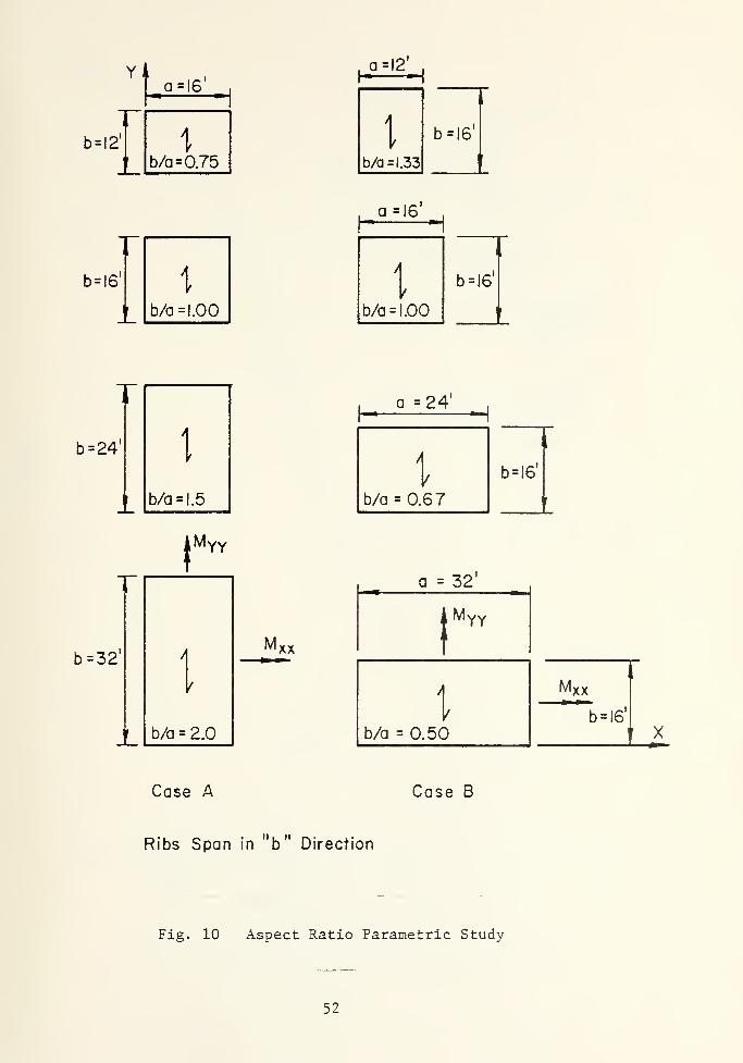
5. PARAMETRIC STUDY
A limited parametric study was conducted utilizing the pre-
viously discussed finite element model to examine the effects of
various aspect ratios on the two-way flexural behavior of steel-deck-
reinforced concrete slabs. The relative span lengths for the strong
versus the weak direction of the orthotropic slab were of particular
interest. Steel-deck-reinforced concrete slabs, when constructed as
one-way systems, routinely have their ribs spanning the shorter
direction, and current research into two-way behavior has
generally followed this practice. In addition to aspect ratio,
simply supported and fixed edge boundary conditions were examined.
5. 1 Purpose and Scope
The relative distribution of bending moments and stresses in
the two orthogonal directions corresponding to the strong and weak
axes of a steel-deck-reinforced concrete slab is a function of aspect
ratio, edge boundary conditions and the section and material properties
of the particular slab in question. A finite element parametric
study was conducted to quantify the effects of aspect ratio as well
as the effect of simply supported versus fixed edge boundary conditions
A typical steel-deck reinforced concrete slab section (Fig. 2
)
was selected and a finite element analysis was performed for each of
the slab aspect ratios shown in Fig. 10. The relative span lengths
were chosen so as to represent typical spans utilized in one-way steel
deck-reinforced concrete slab construction as well as to represent
27


typical spans for alternate floor systems constructed of reinforced
or precast concrete.
It is hypothesized that the optimum aspect ratio for a steel-
deck-reinforced concrete slab is one in which the maximum concrete
compressive stresses are equal in the main orthogonal directions of
the slab. An expression for optimum aspect ratio is developed, based
upon uncracked, elastic behavior, and is compared with the results of
the parametric study.
5.2 Results
Deflection and moment coefficients are compared with slab aspect
ratio in Figs. 11 and 12 respectively. Nondimensionalized coeffi-
cients for deflections and moments were developed based upon the
corresponding expressions for one-way flexural behavior. In general
terms, the coefficients are defined as follows:
184 A FTDEFLECTION COEFFICIENT = a c.j. ^ ^ ^^^
w b
where A = center deflection; and
MOMENT COEFFICIENT = r^ =p- 5.2
where M and L correspond to the appropriate weak or strong direction
values. As shown in Figs. 11 and 12, the slab ribs span in the "b"
direction (strong direction), and an aspect ratio of zero corresponds
to one-way bending. For aspect ratios less than one the ribs span
in the short direction and conversely, the ribs span in the long direc-
tion for aspect ratios greater than one.
28


Figure 11 indicates that for a given span "b", a significant
reduction in maximum deflection can be realized by considering the
effects of two-way flexural action, particularly in the case of
simply supported edges. Although such reduction is more pronounced
for the larger aspect ratios, a 257o reduction in maximum deflections
is predicted for a simply supported slab with a 0.75 aspect ratio.
A 12'xl6' slab with ribs spanning 12 feet^ as shown in Fig. 10, has
an aspect ratio of 0.75 and is a typical panel used in current designs;
however, the added benefit of two-way flexural action is generally
neglected when computing the deflection of such a slab.
If an isotropic slab were considered, the plots of weak and
strong axis moment coefficients shown in Fig. 12 would intersect at
an aspect ratio of 1.0, and for the case of simple supports the
maximum biaxial compressive stress would be balanced at the center.
Assuming that an optimum two-way steel-deck-reinforced concrete slab
design will also attempt to balance the maximum biaxial compressive
stress in the concrete, an expression for the optimum aspect ratio
was derived in Appendix C and is expressed as follows:
Va/opt'^N S \n\i }
x ^xx
where '^ and p, refer to the moment coefficients for the respective
strong and weak direction moments. A trial and error solution for
( — ) utilizing values plotted in Fig. 12 is also shown in\a/opt
Appendix C for the simply supported case. A similar solution for fixed
edges would require optimization with respect to either positive or
negative bending moments.29


The optimum aspect ratio for the simply supported case for the
section shown in Fig. 2 was found to be approximately 1.1. This value
indicates that steel-deck- reinforced concrete slabs subjected to two-way
bending respond more efficiently if their aspect ratio is greater than
one; that is if the ribs span in the longer direction. As mentioned
previously, it is current practice to generally design steel-deck-rein-
forced concrete slabs as simple, one-way spans with the ribs spanning
the short direction. The potential advantages of utilizing two-way
simple or continuous spans are quite apparent from the comparisons
illustrated in Fig. 12.
30


6. CONCLUSIONS AND RECOMMENDATIONS
The concept of designing steel-deck-reinforced concrete slabs
as two-way flexural systems is technically feasible and suggests
strong potential for significant economic advantages. Although this
conclusion is drawn based upon a simplistic uncracked, linear elastic
analysis, it is reasonable to assume that the same behavioral trends
will persist in the cracked region and that the two-way steel-deck-
reinforced concrete slab will performed consistently better than its
one-way counterpart. Although Porter observed predominately one-
way action of two-way steel-deck-reinforced concrete slabs at ultimate
load, significant two-way action was observed at working load levels
despite cracking of the slab cross section. Such behavior suggests
the possibility of developing working stress design procedures
utilizing linear elastic analysis of the cracked cross section at
the working load level. Such analysis techniques are currently
utilized in the design of one-way steel-deck-reinforced concrete slab
systems. However, two-way design of such slab systems will necessarily
require the utilization of supplementary reinforcement transverse and
possibly parallel to the steel deck ribs. As Porter observed, such
reinforcement, placed directly on the steel deck resulted in increased
ultimate capacity when the slab was subjected to two-way bending. Supple-
mentary reinforcement is required not only to resist bending moments,
but also to maintain the same relative stiffness between the weak and
strong axes of the cracked and uncracked cross section of the steel-
deck-reinforced concrete slab.
31


As discussed in the parametric study, a two-way steel-deck rein-
forced slab will perform more efficiently if the ribs span in the
longer direction. This observation and the theoretical prediction
for optimum aspect ratio must necessarily be confirmed by actual
experimentation.
The elastically orthotropic finite element model was found to
perform both effectively and efficiently with a relatively coarse
discretization. However, the model was particularly sensitive to
the expression utilized for the orthotropic shear modulus G andxy
actual testing is required to further validate all model parameters.
As mentioned in Art. 2.3, the model includes an "artificially high"
bending rigidity in the weak direction; however, correlation with
theoretical and experimental results supports the validity of the
parameters which contribute to the model's weak direction bending
ridigidy
.
The difficulties associated with premature shear bond failure
as well as the structural adequacy of the steel-decking during the
construction phase must necessarily be considered in any refined
development of the concept of designing steel-deck-reinforced concrete
slabs as two-way flexural systems. The relative shear-bond and
flexural behavior of interior versus exterior floor panels in a
general two-way framing scheme would be of particular interest.
Although the full benefits of two-way flexural behavior may
be significantly limited by various physical or practical constraints,
32


the relative advantages of two-way versus one-way design of steel-
deck-reinforced concrete slabs are quite apparent. Moreover, the
increased efficiency of a two-way steel-deck-reinforced concrete
slab, cocnbined with the other numerous advantages inherent in this
construction system, will significantly enhance its acceptability for
utilization in multiunit residential facilities.
A considerable amount of additional research is required before
a generally acceptable two-way design procedure could be promulgated.
The analytical techniques developed in this report must be validated
against specific test results and refined as necessary. A full scale
testing program, which parallels and expands upon the parametric
study included in this report, is also imperative. In particular, the
following parameters should be examined:
a. Concrete weight and strength
b. Steel deck cross section and embossment pattern
c. Slab and deck thickness
d. Boundary conditions
e. Aspect ratio, span length, and rib direction
f. Loading
g. Supplementary reinforcement
The required amount of supplementary reinforcement will significantly
effect both the technical and economic feasibility of fully developing
two-way flexural action, and should receive careful attention during
the testing phase. Additionally, trial designs should be prepared for
various sections and general economic comparisons should be made with
33


alternate floor systems of equivalent capacity to ascertain both the
physical and economical efficiency of a steel-deck-reinforcement concrete
slab.
Composite structural systems, in general, offer increased load
carrying efficiency by utilizing each component material in its most
effective manner and to its fullest potential. The steel-deck-rein-
forced concrete slab is currently under-utilized as a structural sys-
tem; however, a much greater efficiency could be achieved by fully
investigating and eventually taking advantage of two-way flexux-al
behavior.
34


7. NOMENCLATURE
C ,C ,C plane stress elasticity constantsxx' yy' xy
D.D ,D flexural rigidity constantsX y
D torsional rigidity constantxy
E,E ,E modulus of elasticity (concrete; steel)
E ,E orthotropic modulus of elasticityX y
G orthotropic shear modulusxy
H effective torsional rigidity constant; total steel-deck-
reinforced slab depth
I transformed uncracked moment of inertia
I transformed uncracked strong axis moment of intertiay
per unit width
I uncracked weak axis moment of inertia per unit width ofX
slab of depth h
I effective uncracked weak axis moment of inertia per unitxe
width
L span length
moment per unit width
center moments per unit width for simply supported edges
center moments per unit width for fixed edges
edge moments per unit width for fixed edges
elastic section modulus
SS simple support
a weak direction span
a. modular width of steel-deck-reinforced concrete slab section
35
M,M ,Mxx' yy
m",XX'
,Myy
XX
XX yy
S ,Sy X


b strong direction span
b/a aspect ratio
f ,f concrete stressex cy
f ultimate concrete strengthc
f yield stress of steely
h total depth of concrete above steel deck ribs
q,q uniform load distribution (plate bending equations)o
t rib thickness
t effective uniform thickness of the elastically ortho-e
tropic slab model
t thickness of the steel decks
w deflection surface; uniform load per unit area
w weight of concretec
x,y global coordinate axes
A center deflection
5 finite summation
a ratio of h/H; deflection coefficient for orthotropic
plate bending
3,,B^ moment coefficients for orthotropic plate bending
V coefficient of torsional rigidity
V shear strainxy
6 deflection coefficient
e jS linear strainXX yy
u.LL ,LL moment coefficients'^^xx '^yy
v,v ,v Poisson' s ratio (concrete; steel)c s
V ,v orthotropic Poisson ratiosX y
'^
36


a ,a normal stressXX yy
T shear stress (equals T for an orthotropic plate withxs xy
principal axes of orthotropy coinciding with the x and y
axes of the local coordinate system)
37


8. TABLES
38


Table 1 Section and Material Properties
Property Value
I 278.7 in*
Iy
23.2 in*/in
IX 3.57 in*/in
Ixe 4.63 in* /in
Sy
7.864 in=/in
sX 2.427 in^/in
c3000 psi
wc
150 pcf
Ec
3320 ksi
Vc
0.2
fy
36 ksi
Es
29,500 ksi
Vs
0.3
ts
0.0359 in (20 gage)
39

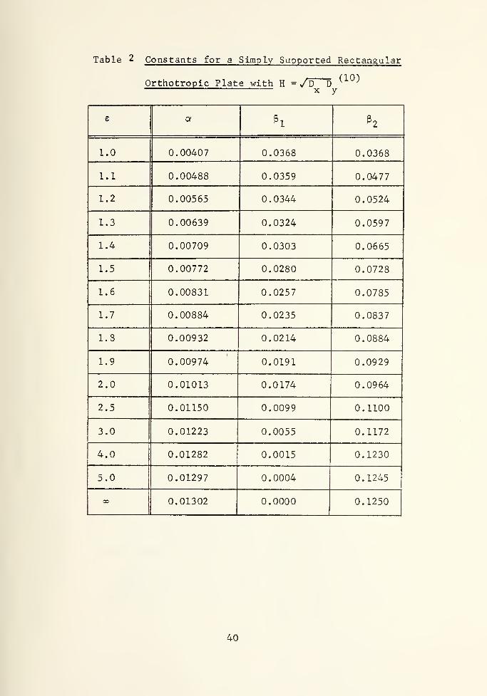
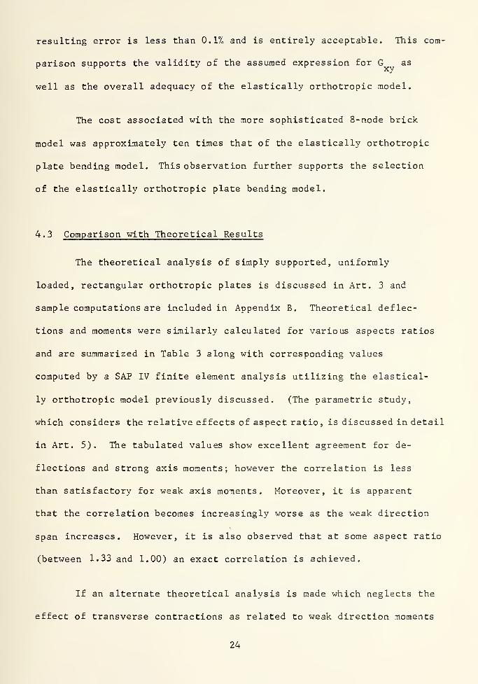
Table 2 Constants for a Simply Supported Rectangular
(10)Orthotropic Plate with H = /D D^ y
e a ^1 h
1.0 0.00407 0.0368 0.0368
1.1 0.00488 0.0359 0.0477
1.2 0.00565 0.0344 0.0524
1.3 0.00639 0.0324 0.0597
1.4 0.00709 0.0303 0.0665
1.5 0.00772 0.0280 0.0728
1.6 0.00831 0.0257 0.0785
1.7 0.00884 0.0235 0.0837
1.8 0.00932 0.0214 0.0884
1.9 0.00974 0.0191 0.0929
2.0 0.01013 0.0174 0.0964
2.5 0.01150 0.0099 0.1100
3.0 0.01223 0.0055 0.1172
4.0 0.01282 0.0015 0.1230
5.0 0.01297 0.0004 0.1245
OS 0.01302 0.0000 0.1250
40


CO
u1—1
3CO
0)
on
I-l
<u
13OS4J
cQJ
S<Ur-<
w(Uu•Hc•Hfa
T)CCO
1—1
CO 0)
o CO•H CO
U <J
(U
o0)
o^ •
H 60
U-l fao
(U
c <u
o CO
CO v^'
•HU cCO o y<~S
Q •H CO y-i
G u (U CO
O o 60 Q.U 0) 13
!-i QJ <t1-1 <!
roT3
i-i^ U
^1 -HjO C O COCO •H CL^H a.
d 3 '-^
CO CD OCL oCO
1—
(
to a. II
Xi e•H •H OCci m cr
^ ^
CO
(U4J
O2
^< 00 <t o 1—1
o O vO 00 en•H I—
1
oo in <tU * • * •
/»-N CO i-H o o od d Oio 1-1
•H ^•^^
U CLo •H O en •vj- v£>
<u ^ eu o i-t in CTn
;j < 00 r-- <f C>J
•H d CO • •
Q •H o o o d
CO CO >.QJ O >,S S
t^ CM in en v£>
!-i Cv4 CM i<00 •5<00
O r^ 00 *r- •J<vO
QJ » *
x: o o d dH
J< <J- r~. <f <i-O U-) CO r-^ o1-1 ON 0^ o o4J • • • »
d ^-v CO o O 1—1 T—
1
o d PiT-< 1-1
u ~-^
u D-QJ tA m CNJ <!• in>-i ^ Pu CM 1—1 00 <}•H 1 < r^ r- 00 enQ d CO • • •
i-< I—
1
CN CO -*ao ^^do CO X(-1 O Xjj Sw >, as OO CM \£>
^ o <f en CMo 00 r^ 00 enQJ • • • 9
s: 1—1 CM en <tH
54 en en in oO v£) CTn 00 o1-1 0^ 0^ c^^ o4J • « • *
CO O o o f-H^-^ Oid1-1
"-^
CO r^ LPl CM r^d P- <J- en CM ino <: 00 en C7^ i-H
•r-l CO o T—
1
I—
1
CM4J . .
O d o o OQJ
I—
1
M-l
QJ
Q >, o in <! inI-l 00 <f <^ <!•
o 00 en CO 1—1
QJ o I—
1
I—
1
r-l
jd • .
H o o o o
4-1 C)^-^ en o p^ o
O 1-( CO en o vO o<U 4-1 ^, en o vD mCL CCi XI • « • «
CO a; v-' I—
1
I—
1
O o<
o
CO >>o >,S
QJ
4-1
VQJ
1—1
60CU
d
(U
V4(0
do1-1
uCJ
CO
u4Jdou
0)
CO
1^
4)
>CO
dCO
!-<
4J
M-l
O
OQJVHIWQJ
>, XJ
O^ !-i QJ
< O S-4
CO QJ or^ QJ4J
4J
CO
QJ
x:
M-l
00
00
in
enmCTi
on
o1-1
ijCO
u
CM00CM
CO >, CO >,
oom
CO
XI
CO
41


9. FIGURES
42

steel Decking
Section
Plan View
(a) One -Way Steel- Deck - Reinforced Concrete Slab
I
h
Plan View
Partition
MMmmM
Section
(b) Two-way Flat Plate Concrete Slab
Fig. 1 Alternate Conventional Floor Systems
43


12" == ai
6" X 6"
Fig. 2 Typical Cross-Section
44


(a) Actual Slab - Structurally Orthotropic
( b ) Lower Bound ( c ) Upper Bound
(d) Slab Model - Elastically Orthotropic
Fig. 3 Model Development
45


43 - Nodal Points
12 - 8 - Node Bricks (concrete)
12 - Plate Bending Elements (steel deck)
Fig. 4 Structurally Orthotropic Finite Element Model
46


16'
CD
- Quarter Symmetry
Utilized in Model
Discretization
- 81 Nodal Points
- 64 Plate Bending Elements
1'
CD
@CO
1
8® 12"= 96"
(JH
(L
Fig. 5 Typical Finite Element Model Discretization
47


0.136
0.135
0.134
a:
H 0.133
LxJ
O
0.132
0.131
0.130
A Center vs. Element Size
Notes: -Simple Supports
-Quarter Symmetry ^^ ^^Used
A "Exact" = 0.1345"
6"x6"
CD'
"cof
Full Slab
t2"xl2"
ELEMENT SIZE
Fig. 6 Convergence Study - Deflections
24"x24"
48


Maximum Moments vs. Element Size
2.85
2.80
96" 96"
96" %96"
'
llf- ,11
.E 2.75 Mstrong Exact =2.748
Simple Supports
Quarter Symmetry Used
0.90
Mweak "Exact" =0.825
COQ.
I
0.85
0.80 -^
a.
I
2.70
'xo
co
« 2.65Mweak "Exact" = 0.688
""(7="C))
0.75
.2'xo
o
0.70 ^^
2.60
2.556"x6"
Mstrong
•— M^eak
I2"xl2"
ELEMENT SIZE
Fig. 7 Convergence Study - Moments
0.65
0.60
24"x24"
49


COa.
CL
Load vs. Centerline Deflection
Schuster a Ekberg Beam 8II6-70-I9-I9SG
24'
J.55'
TSection A-A
Test Data
SAP W: ModelUncracked
• SAP 12" ModelCracked
0.2 0.4 0.6
A (L/IN.
0.8 .0
Fig. 8 Comparison of Model and Test Results (One-way Bending)
50


Load vs. Center Deflection
Porter a Ekberg Two- Way Slab No. 3
a.
Typical Section
//
/
Final LoadCycle
Test Results
SAP ModelUncracked
^CENTEr/'N.
Fig. 9 Comparison of Model and Test Results (Two-way Bending)
51

b=l2
Y-a=l6'
"
A
b/a=0.75
a =12'
I" ^
,
A
b = l6'
b/a=l.33 '
b=l6'A
JL b/a = l.00
a =16
A
V
b/a = l.00
b = l6'
b=24' 1
b/a = l.5
a =24'
b = l6
,MYY
b = 32
' b/a =
f
2.0
M XX
a = 32'
Case A Case B
Ribs Span in "b" Direction
Fig. 10 Aspect Ratio Parametric Study
52


HLJ<COro
5 Ya^s^ a
-a
- .
-
\ SS
\wwwA
ss b
\\\
\\
I X\ <;«; \\\\^\ ^
4
\ A = Center Deflection
-
\ Deflection Coeff. = ^^^^^ = 8
3 —
Ds
-
\ Fixed Edges
2
1
- \1
0.5 —
1 1 "r0.5 1.0 1.5
ASPECT RATIO (b/ai
2.0 2.5
Fig. 11 Deflection Coefficient vs. Aspect Ratio
53


CO
5
>->-
CVJ
o
1.0 1.5
ASPECT RATIO (b/a)
Fig. 12 Moment Coefficients vs. Aspect Ratio(Simple Support & Fixed Edges)
54


10. APPENDICES
55

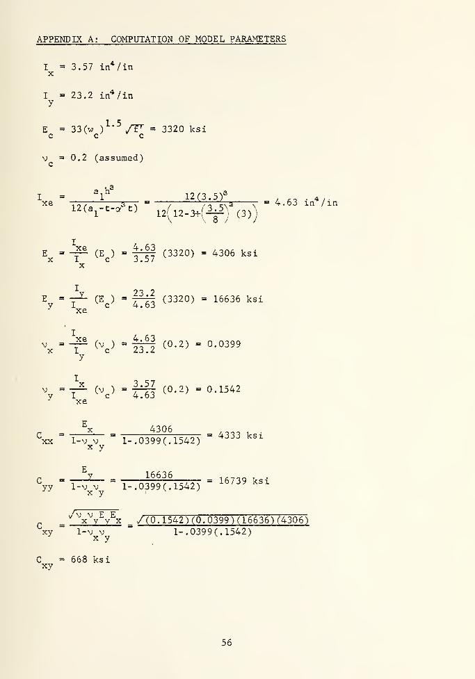
APPENDIX A: COMPUTATION OF MODEL PARAMETERS
I = 3.57 in*/iaX
I = 23.2 in*/iny
E = 33(w )^*^/r' = 3320 ksic c c
V = 0.2 (assumed)c
a,h® ,._ .,3I = 1 12(3. 5r , .. .4/.xe T77-—::—STT = —
;; ^T' ^.5 :: = 4.63 m /in12(a^-t-c. t)
i2(i2-3f(-^) (3))
E = -7^ (E ) = 4^ (3320) = 4306 ksiX I c 3.57
X
E = —^ (E ) = y^ (3320) = 16636 ksiy I c 4.63' xe
V = -p (v ) = -If^ (0.2) = 0.0399x I C ZJ ./
y
\=7^ (^c)=lii (0-2) =0.1542•^ xe
^ ^x 4306 /q-5-^ v •
^xx ' 1-v V " 1-.0399(.1542) ~ '^^^^ ^^^X y
16636 -,^_^ ,.= 16739 ksi
yy 1-v V 1-. 0399 (.1542)X y
'^\^y^y^x _ / (0. 1542) (0.0399) (16636) (4306~)
xy " 1-v V " 1-. 0399 (.1542)x y
C = 668 ksixy
56

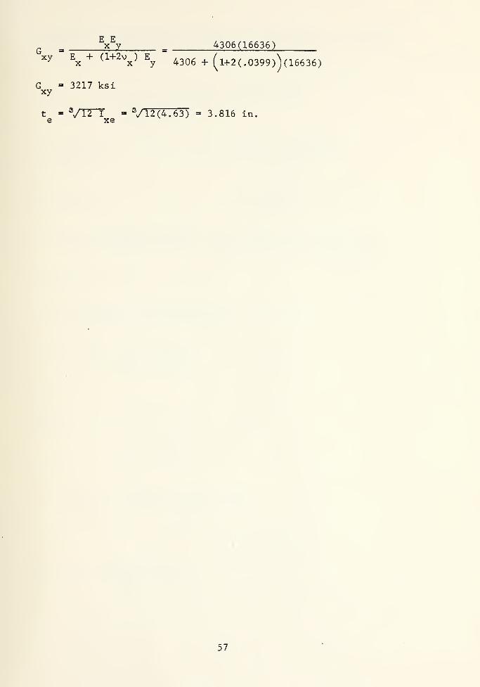
^ ^x^V 4306(16636)'xy
" E + (l+2v ) EX X -V 4306 + ^l+2(.0399)Vl6636)
G = 3217 ksixy
t = ^/n^ = V 12 (4. 63) = 3.816 in.e xe
57


APPENDIX B: COMPUTATION OF THEORETICAL DEFLECTIONS AND MOMENTS
a = b = 16 ft = 192 In. (simply supported edges)
q = 0.001 ksi (144 psf)o
C = 4333 ksiXX
E = E = 3320 ksic
C = 16739 ksiyy
V = 0.0399x
C = 668 ksixy
V = 0.1542y
E a^h°3320 (12) (3.5)^
X'
(l-v;)(12)(a^-t+o^t) =(1.0.1542= )(12)(l2-3-f{^)%3))
D = 15761 in-kipX ^
^ ^ E I 3320 (278.7) _ __.-. . , .
^ =(l-v^)(a,) - (1-.0399^)(12) " ^^^^^ ^^"^^P
D- 1 4 / _Z _ 121 4 /77230
® " b V D "192 a/i5761X
e = 1.488
From Table 1: a = 0.007 644
3^ = 0.028276
^2 = 0.072044
,4^ ^o 0.007644 (.001) (192)^
^ ° D 77230y
XX V^2 ^1 C V D J^oyy X
w = 0.1345 in.
58


"xx= (0-0"044 + 0.028276(^)7SI|) .ooi (192;
M =2.748 in-kip/inXX
C / D , q a^
{h-hfJf)-^.Myy XX y
M^^ - (0.023276 . 0.07204<^)Jl) ^^^LJ^^
M = 0.825 in-kip/inyy
Note: If transverse contractions are neglected (v = v =» C = 0),X y xy
deflections and moments are similarly computed as follows:
w = 0.1361 in
M = 2.684 in-kip/in
M =» 0.688 in-kip/inyy
59


APPENDIX C: OPTI^fUM ASPECT RATIO (see Fig. 12)
For uncracked, linear elastic behavior:
M Mf =-^ f =-fS (1)ex S cy S
X y
Let f = f ; thereforeex ey
M M-n. = ^££ (2)S SX y
From Eq. 5.2:
M =li w L^ (3)
li w a u w b
Therefore -^ = -^ (4)
X y
After simplif ieation:
b> / !l fc\a/opt V S Vll /
X XX5.3
A trial and error solution for the optimum aspect ratio for a
rectangular, simply supported slab with typical section as shown in
Fig. 2 is included hereafter:
b _ /7.864 /^yya V2.427 Vp
'^xx
b = 1 o /!:j2:= 1.8a N (1
XX
'^xx
60


Aspect Ratio Computed from Computed from
(b/a) Eq. (5) Fig. 12
1.00 0.309 0.262
2.00 1.235 4.114
1.50 0.694 1.310
1.33 0.594 0.825
1.25 0.482 0.660
1.10 0.373 0.377
61


11. REFERENCES
1. Bathe, K. J., Wilson, E. L. and Peterson, F, E.
SAP IV A STRUCTURAL ANALYSIS PROGRAM FOR STATIC AND DYNAMICRESPONSE OF LINEAR SYSTEMS, University of California, Berkeley,Revised, April 1974.
2. Schuster, R. M. and Ekberg, C. E., Jr.
COMMENTARY ON THE TENTATIVE RECOMMENDATIONS FOR THE DESIGN OFCOLD-FORMED STEEL DECKING AS REINFORCEMENT FOR CONCRETE FLOORSLABS, Engineering Research Institute, Iowa State University,Ames, August 1970.
3. Schuster, R. M.
COMPOSITE STEEL- DECK CONCRETE FLOOR SYSTEMS , Journal of theStructural Division, ASCE, Vol. 102, No. ST5, May 1976.
4. Porter, M. L. and Ekberg, C. E., Jr.
DESIGN RECOMMENDATIONS FOR STEEL DECK FLOOR SLABS, Journal ofthe Structural Division, ASCE, Vol. 102, No. STll, November 1976.
5. Porter, M. L. and Ekberg, C. E., Jr.
SHEAR- BOND ANALYSIS OF STEEL-DECK-REINFORCED SLABS, Journalof the Structural Division, ASCE, Vol. 102, No. ST12, December1976.
6. Porter, M. L. and Ekberg, C. E., Jr.
BEHAVIOR OF STEEL- DECK- REINFORCED SLABS, Journal of theStructural Division, ASCE, Vol. 102, No. ST3, March 1977.
7. H. H. Robertson CompanyQ-FLOOR SYSTEMS: TECHNICAL DATA GUIDE Q-147TD-75, Pittsburgh,Pa. , January 1975.
8. Troitsky, M. S.
ORTHOTROPIC BRIDGES THEORY AND DESIGN, The James F. LincolnArc Welding Foundation, Cleveland, Oh., August 1967.
9. Szilard, R.
THEORY AND ANALYSIS OF PLATES, Prentice-Hall, Inc., New Jersey,1974.
10. Timoshenko, S. P. and Woinowsky-Krieger , S.
THEORY OF PLATES AND SHELLS, 2nd Edition, McGraw-Hill, NewYork, 1959.
62


ThesisK87628c.l
177907
KubicTwo-way flexural
behavior of steel-
deck- reinforced con.
Crete slabs.
7
l
IThesis
K87628c.l
Kubic ^77907
Two-way flexural
behavior of st****!-
decl<- re info reed con-
crete slabs.

Related Documents