chemical engineering research and design 9 1 ( 2 0 1 3 ) 778–788 Contents lists available at SciVerse ScienceDirect Chemical Engineering Research and Design journal h om epage: www.elsevier.com/locate/cherd Two-step design protocol for patterned groove micromixers Izidor Sabotin a,∗ , Gianluca Tristo b , Mihael Junkar a , Jo ˇ sko Valentinˇ ciˇ c a a Department of Manufacturing Technologies and Systems, University of Ljubljana, Aˇ skerˇ ceva 6, 1000 Ljubljana, Slovenia b Department of Industrial Engineering, University of Padua, Via Venezia 1, 35131 Padua, Italy a b s t r a c t Micromixers are essential components of microreactor technology. In this paper, a simple two-step design protocol for patterned groove micromixers based on numerical simulations is presented. In the first step, one groove of the staggered herringbone micromixer (SHM) is designed based on the average magnitude of transversal velocity v AVGyz at the end of the groove. In the second step, different configurations of six grooves are investigated. A slightly better mixing is achieved compared to the established SHM and significantly fewer grooves are needed. Due to fewer grooves and rounded groove corners, the new design is easier to be produced by microengineering technologies (MET). Additionally, good mixing was also achieved with a modified slanted groove micromixer (SGM) configuration with the largest rounding radius at the edges. A SGM prototype was machined by micro EDM milling. The simulation results were experimentally verified with flow visualization and a good agreement was observed. The presented protocol vastly reduces the number of optimal patterned groove geometry configuration candidates to be evaluated; it is simple and effective for practical applications. © 2012 The Institution of Chemical Engineers. Published by Elsevier B.V. All rights reserved. Keywords: Micromixer; Design; Microreactor technology; Microfluidics; FEM simulations; Micro EDM milling 1. Introduction Miniaturization is a recent trend in analytical chemistry and life sciences as well as in non-silicon micromachining tech- nologies (Alting et al., 2003; Hessel et al., 2005). In the past two decades, miniaturization of fluid handling and fluid analysis has emerged in the interdisciplinary field of microflu- idics. Micromixers are important components of microfluidic systems. Rapid mixing is essential in many of microfluidic sys- tems used in biochemistry analysis, drug delivery, sequencing of synthesis of nucleic acids as well as in microreactor systems (Cvjetko and ˇ Znidarˇ siˇ c-Plazl, 2011; Du et al., 2010; Nguyen and Wu, 2005; Pohar and Plazl, 2009). Its function is to mix the reactants for initiation of the reaction process, and it is an indispensable component in lab-on-a-chip (LOC) platforms for complex chemical reactions. Micromixers can be integrated in a microfluidic system or work as stand-alone devices. To mix solutions at the microscale is a difficult task. Under typical low Reynolds number operating conditions (Re < 100) the fluid flow is laminar. The absence of turbulent flow pat- terns and a slow diffusion process are the main challenges ∗ Corresponding author. Tel.: +386 01 4771 774; fax: +386 01 4771 759. E-mail addresses: [email protected], [email protected] (I. Sabotin), [email protected] (G. Tristo), [email protected] (M. Junkar), [email protected] (J. Valentinˇ ciˇ c). Received 18 May 2012; Received in revised form 13 September 2012; Accepted 25 September 2012 to overcome in order to achieve mixing. The ratio between the mass transport due to advection and that of diffusion is defined by Peclet number Pe = VL/D where V denotes mean fluid velocity, L is a characteristic linear dimension of the channel geometry and D is a mass diffusion coefficient. In microchannels, the Peclet number is typically higher than 100, meaning a very slow diffusion process with respect to advec- tion (Squires and Quake, 2005). In contrast to active micromixers, where an additional source of energy has to be introduced into the microfluidic system, passive micromixers depend solely on pressure driven flow. Therefore they are robust, stable in operation and easily integrated into more complex systems. One of the estab- lished passive micromixing mechanisms is inducing chaotic advection by patterning the inner channel walls with oblique grooves (Du et al., 2010; Johnson et al., 2002; Kim et al., 2004; Sato et al., 2006; Stroock et al., 2002; Tofteberg et al., 2010; Williams et al., 2008). The concept of bottom grooved micromixers was originally developed by Stroock et al. (2002) and attracted a lot of research interest due to the good mixing efficiencybelow Re < 50, small 0263-8762/$ – see front matter © 2012 The Institution of Chemical Engineers. Published by Elsevier B.V. All rights reserved. http://dx.doi.org/10.1016/j.cherd.2012.09.013

Welcome message from author
This document is posted to help you gain knowledge. Please leave a comment to let me know what you think about it! Share it to your friends and learn new things together.
Transcript
chemical engineering research and design 9 1 ( 2 0 1 3 ) 778–788
Contents lists available at SciVerse ScienceDirect
Chemical Engineering Research and Design
journa l h om epage: www.elsev ier .com/ locate /cherd
Two-step design protocol for patterned groove micromixers
Izidor Sabotina,∗, Gianluca Tristob, Mihael Junkara, Josko Valentincic a
a Department of Manufacturing Technologies and Systems, University of Ljubljana, Askerceva 6, 1000 Ljubljana, Sloveniab Department of Industrial Engineering, University of Padua, Via Venezia 1, 35131 Padua, Italy
a b s t r a c t
Micromixers are essential components of microreactor technology. In this paper, a simple two-step design protocol
for patterned groove micromixers based on numerical simulations is presented. In the first step, one groove of
the staggered herringbone micromixer (SHM) is designed based on the average magnitude of transversal velocity
vAVGyz at the end of the groove. In the second step, different configurations of six grooves are investigated. A slightly
better mixing is achieved compared to the established SHM and significantly fewer grooves are needed. Due to fewer
grooves and rounded groove corners, the new design is easier to be produced by microengineering technologies
(MET). Additionally, good mixing was also achieved with a modified slanted groove micromixer (SGM) configuration
with the largest rounding radius at the edges. A SGM prototype was machined by micro EDM milling. The simulation
results were experimentally verified with flow visualization and a good agreement was observed. The presented
protocol vastly reduces the number of optimal patterned groove geometry configuration candidates to be evaluated;
it is simple and effective for practical applications.
© 2012 The Institution of Chemical Engineers. Published by Elsevier B.V. All rights reserved.
Keywords: Micromixer; Design; Microreactor technology; Microfluidics; FEM simulations; Micro EDM milling
developed by Stroock et al. (2002) and attracted a lot of research
1. Introduction
Miniaturization is a recent trend in analytical chemistry andlife sciences as well as in non-silicon micromachining tech-nologies (Alting et al., 2003; Hessel et al., 2005). In the pasttwo decades, miniaturization of fluid handling and fluidanalysis has emerged in the interdisciplinary field of microflu-idics. Micromixers are important components of microfluidicsystems. Rapid mixing is essential in many of microfluidic sys-tems used in biochemistry analysis, drug delivery, sequencingof synthesis of nucleic acids as well as in microreactor systems(Cvjetko and Znidarsic-Plazl, 2011; Du et al., 2010; Nguyen andWu, 2005; Pohar and Plazl, 2009). Its function is to mix thereactants for initiation of the reaction process, and it is anindispensable component in lab-on-a-chip (LOC) platforms forcomplex chemical reactions. Micromixers can be integrated ina microfluidic system or work as stand-alone devices.
To mix solutions at the microscale is a difficult task. Undertypical low Reynolds number operating conditions (Re < 100)the fluid flow is laminar. The absence of turbulent flow pat-
terns and a slow diffusion process are the main challenges∗ Corresponding author. Tel.: +386 01 4771 774; fax: +386 01 4771 759.E-mail addresses: [email protected], izidor.sabotin@gmai
[email protected] (M. Junkar), [email protected] (J. VReceived 18 May 2012; Received in revised form 13 September 2012; A
0263-8762/$ – see front matter © 2012 The Institution of Chemical Engihttp://dx.doi.org/10.1016/j.cherd.2012.09.013
to overcome in order to achieve mixing. The ratio betweenthe mass transport due to advection and that of diffusion isdefined by Peclet number Pe = VL/D where V denotes meanfluid velocity, L is a characteristic linear dimension of thechannel geometry and D is a mass diffusion coefficient. Inmicrochannels, the Peclet number is typically higher than 100,meaning a very slow diffusion process with respect to advec-tion (Squires and Quake, 2005).
In contrast to active micromixers, where an additionalsource of energy has to be introduced into the microfluidicsystem, passive micromixers depend solely on pressure drivenflow. Therefore they are robust, stable in operation and easilyintegrated into more complex systems. One of the estab-lished passive micromixing mechanisms is inducing chaoticadvection by patterning the inner channel walls with obliquegrooves (Du et al., 2010; Johnson et al., 2002; Kim et al., 2004;Sato et al., 2006; Stroock et al., 2002; Tofteberg et al., 2010;Williams et al., 2008).
The concept of bottom grooved micromixers was originally
l.com (I. Sabotin), [email protected] (G. Tristo),alentincic).ccepted 25 September 2012
interest due to the good mixing efficiencybelow Re < 50, small
neers. Published by Elsevier B.V. All rights reserved.
chemical engineering research and design 9 1 ( 2 0 1 3 ) 778–788 779
Nomenclature
a groove width (mm)ap apex positionb ridge length (mm)c concentration (mol/m3)cxn concentration at a single point in yz-cut plane
at channel length xc average concentration for a homogeneous mix-
tureCoVx coefficient of variance in yz-cut plane at chan-
nel length xD mass diffusion coefficient (m2/s)d groove depth (mm)h height of the channel (mm)L characteristic linear dimension of the channel
geometry (m)N number of sample pointsp pressure (Pa)Pe Peclet numberRe Reynolds numberrgroove radius of groove corner roundings (�m)V average fluid velocity (m/s)v velocity vectorvAVGyz average magnitude of transversal velocity (m/s)w width of the channel (mm)x coordinate in the direction of channel lengthy coordinate in the direction of channel widthz coordinate in the direction of channel height
Greek letters� density (kg/m3)� dynamic viscosity (Pa s)
pigm(Saaett
Fcho
ressure drop, and established soft lithographic methods forts fabrication (Nguyen and Wu, 2005). The most commoneometries of grooved micromixers are the slanted grooveicromixer (SGM) and the staggered herringbone micromixer
SHM), both embedded on the floor of the microchannel. TheGM grooves are inclined at an angle with respect to thexial direction, whereas the SHM grooves have the shape of
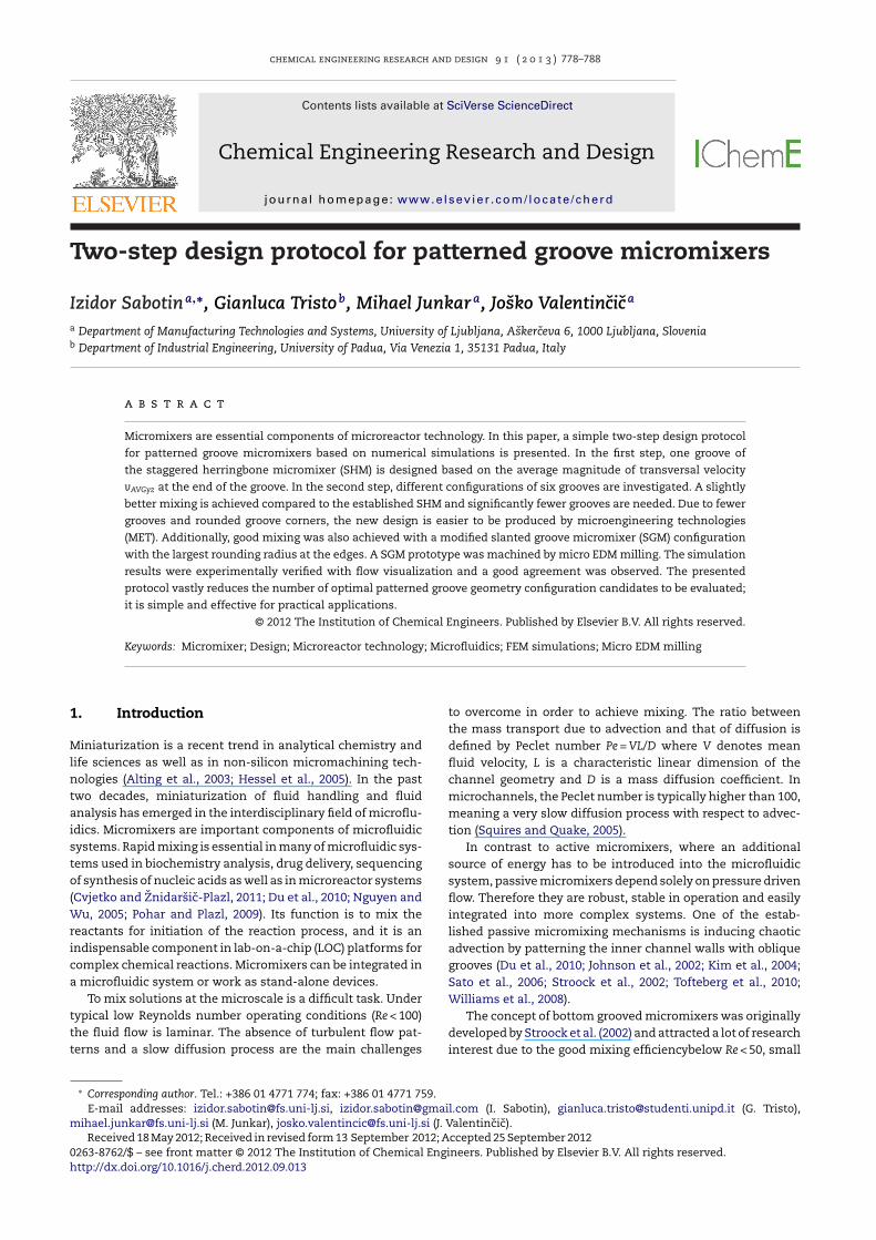
herringbone pattern (Fig. 1). The advection of the fluid isnhanced through its transport along the oblique grooves to
he downstream edges of the microchannel. Consequently,he fluid in the upper part of the channel starts to rotate inig. 1 – (a) Typical geometry of the slanted groove micromixer (SGhannel cross-section. (b) Geometry of the staggered herringboneelical motion caused by the groove geometry. One full cycle is criented the same way.
the opposite direction causing a helical flow pattern. The her-ringbone pattern of the SHM generates two counter-rotatinghelical flows and when alternating the asymmetry of theSHM grooves a chaotic flow profile is created. The circulat-ing motion stretches and folds the fluids, which exponentiallyreduces the distance over which different molecules have todiffuse.
To date, there have been a number of theoretical, experi-mental, and numerical studies aimed at the optimization ofSGM and SHM geometry (Ansari and Kim, 2007; Aubin et al.,2005; Du et al., 2010; Fodor et al., 2009; Wang et al., 2003;Yang et al., 2005; Zhang et al., 2008). An analytical approachwas developed by Stroock et al. (2002) to quantify non-axialflow in the SGM. It was shown that flow over shallow obliquegrooves can be accurately modeled by super-positioning theanalytical solution for 2D lid-driven cavity flow in rectangularducts for axial Poiseulle flow (Song et al., 2008; Stroock andMcGraw, 2004). To optimize mixing of SGM and SHM geome-tries using numerical simulations different approaches wereapplied. Hassell and Zimmerman (2006) investigated convec-tive motion through shallow SHM geometries and used severalflow based descriptors such as non-axial velocities at variouscut planes, cross-channel flow within the groove, helicity ofthe flow and dissipation of energy in the fluid due to viscousdissipation. Lynn and Dandy (2007) defined a measure to quan-tify the magnitude of helical flow within the SGM by the ratio ofnon-axial to axial flow, normalized by the groove-ridge widthand the channel width. They avoided the criteria of numeri-cally simulated concentration fields due to possible numericalerrors. Among the methods to quantify SHM and SGM mix-ing efficiency such as particle tracking (Aubin et al., 2003;Kee and Gavriilidis, 2008), striation thickness (Aubin et al.,2005), flow helicity (Hassell and Zimmerman, 2006), length ofstretching (Song et al., 2008), entropic measures (Fodor et al.,2009), the coefficient of variance of the concentration profileis most commonly used (Ansari and Kim, 2007; Yang et al.,2005). Recently, Du et al. (2010) used concentration profilesversus channel length, so-called concentration streamlines,as the only mixing criterion and verified the simulation resultsthrough fluorescent quenching experiments thus proving thatnumerically solved convection-diffusion equations give reli-able information about mixing.
Experimentally, numerically simulated mixing behaviorcan be verified through the imaging of the concentration pro-file on the surface of the see-through micromixers (Hessel
et al., 2003) or by studying the change of color due to somechemical reactions of the fluid phases (Du et al., 2010; JohnsonM) and the schematic representation of streamlines in the micromixer (SHM) and schematic representation of double
omposed of two half-cycles, one half-cycle has grooves

780 chemical engineering research and design 9 1 ( 2 0 1 3 ) 778–788
Table 1 – Presentation of parameters varied and configurations used: a – groove width; d – groove depth; Re – Reynoldsnumber; b – ridge distance; rgroove – corner rounding; and D – diffusion coefficient.
One-groove geometry Six groove geometry, Re = 0.5, D = 10−9 m2/s
a (mm) d (mm) Re b (mm) rgroove (mm) Configurations
0.05–0.30 0.03–0.20 0.5–20 0.05–0.35 0.025, 0.05a SHM, SGM
a Only in configuration of SGM .
rmaxet al., 2002). More detailed information at higher cost canbe obtained by confocal microscopy (Tofteberg et al., 2010;Williams et al., 2008). A comprehensive review on mixing char-acterization in microchannels can be found in Aubin et al.(2010).
The SGM and SHM realizations reported in the literaturehave a lot of shallow grooves on the bottom of the mixingchannel which suits the characteristics of soft lithographicmanufacturing methods (Kim et al., 2004; Williams et al., 2008).Thus, most of the design optimization studies are limited tosmall deviations around the originally proposed low aspectratio groove geometry proposed by Stroock et al. (2002) whichleads to local optimums within confined geometrical dimen-sions. The related papers provide a general trend about thegeometry layout of microstructured grooves and its effects onmixing performance. However, the true optimum design hasyet to be discovered for a specific application through numer-ical simulations (Du et al., 2010).
For a successful micromixer design, it is important to con-sider the fabrication methods. In addition, microengineeringtechnologies (MET) such as laser ablation, micromilling, andmicro EDM milling enable the fabrication of long life toolsusing, for example hardened steel or ceramics (Alting et al.,2003). Thus, mixing performance of every single groove isessential to minimize the costs of micromixer fabrication.
In this paper, a straightforward protocol for SH micromixerdesign is presented with an aim to enhance every singlegroove’s mixing performance. The procedure is divided intotwo steps. Firstly, one-groove geometry is designed based onthe criterion of maximal average transversal flow velocityproviding solute-independent information and consequentlyavoiding the non-significant diffusion dynamics of a shortsegment of the one groove. In the second step, favorableone-groove geometry was used in different SHM and SGM con-figurations, applying the coefficient of variance as the measureof mixer performance. The best configuration was bench-marked against established SHM design and the validity ofsimulations was checked with flow pattern visualization.
Presented design protocol is aimed to give the researcherswho are not experts in microfluidics an instructive and effec-tive tool for the patterned groove micromixers’ design. Specialattention is given on the appropriateness of the design tobe machined by non-silicon based micromanufacturing tech-nologies (MET) and their limitations such as inability toproduce sharp inner corners.
2. Materials and methods
2.1. Geometry of the micromixer
Original groove geometry of SHM, proposed by Stroock et al.(2002), was used as a starting geometry for enhanced mixer
design. In Fig. 1(b) a typical SHM configuration is presentedand variables used in this investigation are denoted, namelya for the lateral groove width, d for groove depth and b fordistance between two successive grooves. Primary flow flowsalong the x-axis, the y-axis is in the direction of the channelwidth and z-axis is in the direction of channel height.
The main channel width w and height h were fixed tow = 200 �m and h = 50 �m, since the selected channel size iscommonly used channel cross-section of commercially avail-able microreactor systems (Novak et al., 2012; Znidarsic-Plazland Plazl, 2009). The asymmetry index of SHM grooves wasone third, ap = 1/3 × w, meaning that the apex position of thegroove is positioned at one third of the channel width, sincethat was found to be the optimal apex position in SHM designin the alternating half-cycle configuration (Stroock et al., 2002;Yang et al., 2005). The grooves are patterned at a 45◦ angle tothe x-axis. The total length of a simulated channel varied from1.5 mm for simulations of one-groove geometry to 3.5 mmfor six-groove geometry. Preliminary simulations showed thatonly few newly designed grooves were sufficient to completethe mixing. Thus, the number of grooves for multiple grooveconfigurations was fixed to six in order to show the effective-ness of one-groove design in comparison to established SHMgeometry, and to maintain the design layout compatible withMET, e.g., micro EDM milling. In line with the paradigm ofdesign for manufacturing (DFM) the corners of groove geome-tries in multiple groove configurations were rounded to aminimum radius of rgroove = 25 �m which is readily achievablewith MET (Alting et al., 2003). Investigated groove parametersat different mixing regimes are gathered in Table 1.
2.2. Simulation tool
CFD modeling was performed using Comsol Multiphysics4.1 which implements the finite element method (FEM)for numerical computation of physics governing equations.The numerical simulation was used to solve Navier–Stokesequations for incompressible fluid and convection-diffusionequations at steady state. The governing equations thatdescribe the physical phenomena of mixing are as followed:Navier–Stokes (NS) equations:
�(v · ∇)v − ∇ · �(∇v + (∇v)T) + ∇p = 0, ∇ · v = 0, (1)
and convection-diffusion (CD) equations:
D∇2c − v · ∇c = 0. (2)
In Eqs. (1) and (2), � denotes density (kg/m3), v is the velocityvector (m/s), � denotes viscosity (Pa s), p equals pressure (Pa),D denotes the diffusion coefficient (m2/s) and c represents theconcentration (mol/m3).
Meshing of simulated geometries was implemented by thesoftware applying free mesh elements that can easily adapt
to the structure of the channel. The tetrahedral free mesh-ing method with meshing parameters similar to that reported
chemical engineering research and design 9 1 ( 2 0 1 3 ) 778–788 781
Fig. 2 – (a) Schematic presentation of a single SHM groove geometry and the position of the cut plane where vAVGyz iscalculated. (b) Presentation of non-axial velocity field in yz-direction. Black and white color-coding denotes the amplitude ofv
iBltRtwreroctr1prrsoq
dftiiorbnstopo
2
Ittaoecta
AVGyz.
n literature was used (Du et al., 2010; Williams et al., 2008).riefly, the computation of NS and CD equations was decoup-
ed in order to reduce the computational power needed to runhe simulation on a PC workstation (Intel i7 processor, 24 GBAM). Maximum mesh element size for the main channel ofhe mixer used when solving NS equations was set to 15 �m,hile the mesh in the grooves was set to 5 �m in order to
eliably capture the fluid dynamics in the grooves. Maximumlement size scaling factor was set to 0.2, element growthate to 1.3, mesh curvature factor to 0.2 and the resolutionf the narrow region to 1. Total number of mesh elementsonsisted of 2–6 × 10⁵, depending on the simulated geome-ry. Mesh settings for solving CD equations were similar whileeducing the maximum element size to 10 �m, resulting in–3 × 10⁶ mesh elements. Finer adjustments of the mesh wereerformed in order to obtain the required convergence at aeasonable time scale while maintaining the required accu-acy. The laminar flow terms were discretized using P2 + P1cheme; second order elements for the velocity field and firstrder elements for pressure. For transport of diluted speciesuadratic discretization was employed.
The fluid properties were set to the ones of water at 20 ◦C;ensity � = 998.2 kg/m3 and viscosity � = 1.002 mPa s. The dif-usion coefficient of the solute was set to D = 10−9 m2/s sincehis is a typical value for most ions in aqueous solution. Thenlet flows were set as inflows with average linear fluid veloc-ty according to the Re regime investigated. The optimizationf six groove geometries was conducted only for Re = 0.5, cor-esponding to v = 0.0063 m/s and a Peclet number of 630. Theoundary condition for the outflow was set to 0 Pa (pressure,o viscous stress) and flow velocity at the walls to a no-lip condition (v = 0 m/s). Fluid concentration of one half ofhe channel was set to 1 mol/m3 (color coded red) and thether half to 0 mol/m3 (color coded blue) respectively. Theost processing and visualizations of simulated results werebtained using the associated functions in Comsol and Matlab.
.3. Design protocol
t is known that the mixing of SHM is strongly related towo counter-rotating helical flows caused by the long andhe short arm of the groove. The circulating motion stretchesnd folds the fluids, which exponentially reduces the distancever which molecule species have to diffuse. In literature, thefficiency of SHM was also correlated with creating maximalross-channel fluid transfer. Yang et al. (2005) concluded that
he flow rate within the grooves of the SHM is substantiateds one of the most critical parameters of its efficiency andHassell and Zimmerman (2006) suggested that efficiency ofthe grooves in moving fluid cross-channel could be reason-ably described by the single groove case. Thus, measuring thequantity of the transversal flow is a logical predictor of themixing efficiency. These findings were utilized in presenteddesign protocol.
The enhancement of the micromixer geometry was per-formed in two steps. In the first step, one-groove geometrywas designed based on the criterion of the average transver-sal velocity vector (Eq. (3)). The average square root value of thevelocity vector in directions perpendicular to primary flow (vy,vz) was calculated as:
vAVGyz = 1N
∑i
√v2
yi+ v2
zi(3)
in the cut plane at the end of the single SHM groove (Fig. 2(a)), Ndenotes the number of points in the cut plane. vAVGyz is indi-rectly correlated with entrained fluid in the groove, namely,fluid cross-channel transfer at the end of the groove is a con-sequence of momentum transfer of entrained fluid draggingthe bulk flow due to viscous stresses.
In the second step an optimal 6 groove configuration,within the channel length of 3 mm, were determined by thecoefficient of variance criterion which is commonly applied tostatic mixers (Kukuková et al., 2008):
CoVx =
√(1/N)
∑N
n=1(cxn − c)2
c(4)
where CoVx denotes the coefficient of variance in yz-cut planeat channel length x, cxn denotes the concentration at a point inthe cut plane, N denotes the number of concentration pointsconsidered in the cut plane and c denotes complete mixing,which is 0.5 mol/m3 in our case. Concentration data at eachcut plane was exported in a uniform grid with 2.5 �m spacing(N = 1600 points). A value of CoVx closer to 0 corresponds tobetter mixing performance.
2.4. Experimental setup
Based upon preceding geometry optimization a micromixerprototype was machined by micro EDM milling technologyin the tool steel. The lateral dimensions of the machinedgeometry were measured with optical microscope CETR, UMT
Multi-Specimen Test System at a magnification of 550. Depthof micromixer structures was measured with a laboratory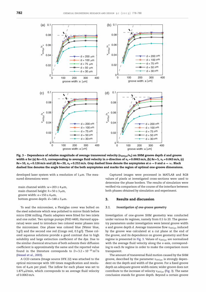
782 chemical engineering research and design 9 1 ( 2 0 1 3 ) 778–788
0 100 200 300 4000
0.02
0.04
0.06
0.08
0.1
groove width: a [μm] [μm]
v AV
Gyz
/vx
d = 200 μmd = 100 μmd = 75 μmd = 50 μmd = 30 μm
μmμmμmμmμm
μmμmμmμmμm
μmμmμmμmμm
0 100 200 300 4000
0.02
0.04
0.06
0.08
0.1
groove width: a
v AV
Gyz
/vx
d = 200 d = 100 d = 75 d = 50 d = 30
0 100 200 300 4000
0.02
0.04
0.06
0.08
0.1
groove width: a
v AV
Gyz
/vx
d = 200 d = 100 d = 75 d = 50 d = 30
0 100 200 300 4000
0.02
0.04
0.06
0.08
0.1
groove width: a
v AV
Gyz
/vx
d = 200 d = 100 d = 75 d = 50 d = 30
(a) (b)
(c) (d)
[μm] [μm]
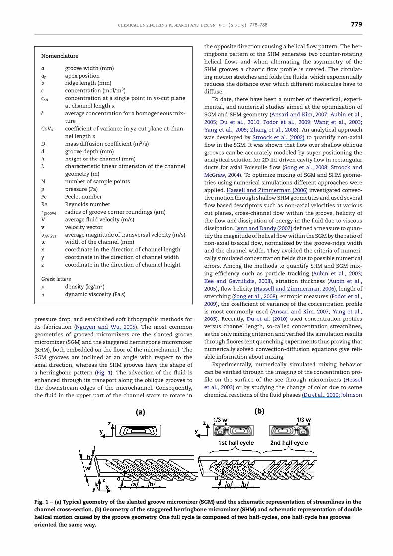
Fig. 3 – Dependence of relative magnitude of average transversal velocity (vAVGyz/vx) on SHM groove depth d and groovewidth a for (a) Re = 0.5, corresponding to average fluid velocity in x-direction of vx = 0.0063 m/s, (b) Re = 5, vx = 0.063 m/s, (c)Re = 10, vx = 0.126 m/s and (d) Re = 20, vx = 0.252 m/s. Gray dashed lines denote the asymptotes at a → 0 and a → ∞. Black
es a
dashed line denotes the angle bisector of the both asymptotdeveloped laser system with a resolution of 1 �m. The mea-sured dimensions were:
main channel width: w = 203 ± 4 �m,main channel height: h = 50 ± 3 �m,groove width: a = 150 ± 4 �m,bottom groove depth: d = 148 ± 3 �m.
To seal the micromixer, a Plexiglas cover was bolted onthe steel substrate which was polished to mirror finish beforemicro EDM milling. Plastic adapters were fitted for two inletsand one outlet. Two syringe pumps (PHD 4400, Harvard appa-ratus) were used to introduce two colored water phases intothe micromixer. One phase was colored blue (Water blue,5 g/l) and the second one red (Congo red, 0.5 g/l). These col-ored aqueous solutions provide a good contrast due to highsolubility and large extinction coefficient of the dye. Due tothe similar chemical structure of both solvents their diffusioncoefficient is approximately the same and the reported valuefound in the literature corresponds to D = 3.2 × 10⁻¹⁰ m2/s(Hessel et al., 2003).
A CCD camera (Image source DFK 22) was attached to theoptical microscope with 100 times magnification and resolu-tion of 4 �m per pixel. The inflow for each phase was set to
1.875 �l/min, which corresponds to an average fluid velocityof 0.0063 m/s.nd marks the region of optimal one-groove dimensions.
Captured images were processed in MATLAB and RGBvalues of pixels at investigated cross-sections were used todetermine the phase borders. The results of simulation wereverified via comparison of the course of the interface betweenboth phases obtained by simulation and experiment.
3. Results and discussion
3.1. Investigation of one-groove geometry
Investigation of one-groove SHM geometry was conductedunder various Re regimes, namely from 0.5 to 20. The geome-try parameters under investigation were lateral groove widtha and groove depth d. Average transverse flow vAVGyz inducedby the groove was calculated at a cut plane at the end ofthe groove, and its dependence on groove geometry and flowregime is presented in Fig. 3. Values of vAVGyz are normalizedwith the average fluid velocity along the x-axis, correspond-ing to each Re regime in order to make the comparison moretransparent.
The amount of transversal fluid motion caused by the SHMgroove, described by the parameter vAVGyz is strongly depen-dent on the depth and width of the groove. For a fixed groovedepth an adequate groove width exists; wider groove does not
contribute to the increase of velocity vAVGyz (Fig. 3). The sameconclusion stands for groove depth. Beyond a certain groove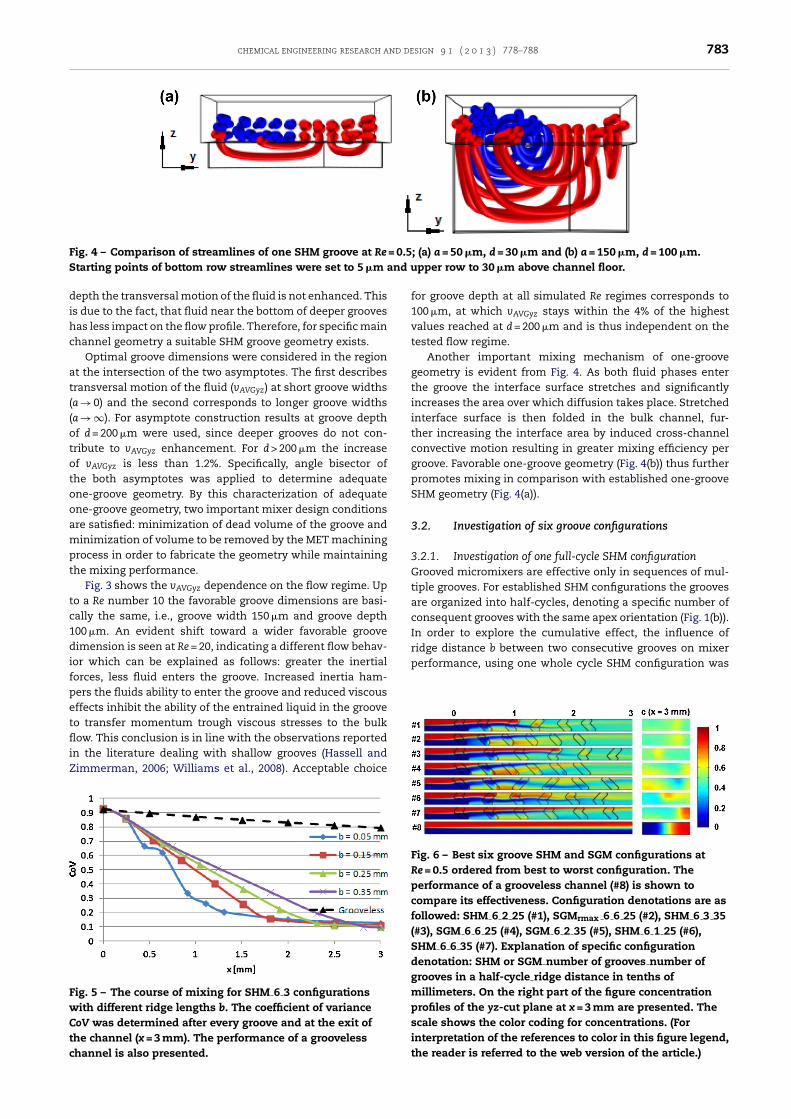
chemical engineering research and design 9 1 ( 2 0 1 3 ) 778–788 783
Fig. 4 – Comparison of streamlines of one SHM groove at Re = 0.5; (a) a = 50 �m, d = 30 �m and (b) a = 150 �m, d = 100 �m.S nd u
dihc
at((ototooampt
tc1difpetfliZ
FwCtc
ridge distance b between two consecutive grooves on mixerperformance, using one whole cycle SHM configuration was
tarting points of bottom row streamlines were set to 5 �m a
epth the transversal motion of the fluid is not enhanced. Thiss due to the fact, that fluid near the bottom of deeper groovesas less impact on the flow profile. Therefore, for specific mainhannel geometry a suitable SHM groove geometry exists.
Optimal groove dimensions were considered in the regiont the intersection of the two asymptotes. The first describesransversal motion of the fluid (vAVGyz) at short groove widthsa → 0) and the second corresponds to longer groove widthsa → ∞). For asymptote construction results at groove depthf d = 200 �m were used, since deeper grooves do not con-ribute to vAVGyz enhancement. For d > 200 �m the increasef vAVGyz is less than 1.2%. Specifically, angle bisector ofhe both asymptotes was applied to determine adequatene-groove geometry. By this characterization of adequatene-groove geometry, two important mixer design conditionsre satisfied: minimization of dead volume of the groove andinimization of volume to be removed by the MET machining
rocess in order to fabricate the geometry while maintaininghe mixing performance.
Fig. 3 shows the vAVGyz dependence on the flow regime. Upo a Re number 10 the favorable groove dimensions are basi-ally the same, i.e., groove width 150 �m and groove depth00 �m. An evident shift toward a wider favorable grooveimension is seen at Re = 20, indicating a different flow behav-
or which can be explained as follows: greater the inertialorces, less fluid enters the groove. Increased inertia ham-ers the fluids ability to enter the groove and reduced viscousffects inhibit the ability of the entrained liquid in the grooveo transfer momentum trough viscous stresses to the bulkow. This conclusion is in line with the observations reported
n the literature dealing with shallow grooves (Hassell andimmerman, 2006; Williams et al., 2008). Acceptable choice
ig. 5 – The course of mixing for SHM 6 3 configurationsith different ridge lengths b. The coefficient of variance
oV was determined after every groove and at the exit ofhe channel (x = 3 mm). The performance of a groovelesshannel is also presented.
pper row to 30 �m above channel floor.
for groove depth at all simulated Re regimes corresponds to100 �m, at which vAVGyz stays within the 4% of the highestvalues reached at d = 200 �m and is thus independent on thetested flow regime.
Another important mixing mechanism of one-groovegeometry is evident from Fig. 4. As both fluid phases enterthe groove the interface surface stretches and significantlyincreases the area over which diffusion takes place. Stretchedinterface surface is then folded in the bulk channel, fur-ther increasing the interface area by induced cross-channelconvective motion resulting in greater mixing efficiency pergroove. Favorable one-groove geometry (Fig. 4(b)) thus furtherpromotes mixing in comparison with established one-grooveSHM geometry (Fig. 4(a)).
3.2. Investigation of six groove configurations
3.2.1. Investigation of one full-cycle SHM configurationGrooved micromixers are effective only in sequences of mul-tiple grooves. For established SHM configurations the groovesare organized into half-cycles, denoting a specific number ofconsequent grooves with the same apex orientation (Fig. 1(b)).In order to explore the cumulative effect, the influence of
Fig. 6 – Best six groove SHM and SGM configurations atRe = 0.5 ordered from best to worst configuration. Theperformance of a grooveless channel (#8) is shown tocompare its effectiveness. Configuration denotations are asfollowed: SHM 6 2 25 (#1), SGMrmax 6 6 25 (#2), SHM 6 3 35(#3), SGM 6 6 25 (#4), SGM 6 2 35 (#5), SHM 6 1 25 (#6),SHM 6 6 35 (#7). Explanation of specific configurationdenotation: SHM or SGM number of grooves number ofgrooves in a half-cycle ridge distance in tenths ofmillimeters. On the right part of the figure concentrationprofiles of the yz-cut plane at x = 3 mm are presented. Thescale shows the color coding for concentrations. (Forinterpretation of the references to color in this figure legend,the reader is referred to the web version of the article.)
784 chemical engineering research and design 9 1 ( 2 0 1 3 ) 778–788
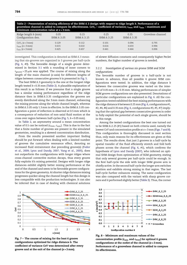
Table 2 – Presentation of mixing efficiency of the SHM 6 3 design with respect to ridge length b. Performance of agrooveless channel is added to compare its effectiveness. CoVx – coefficient of variance; cmax and cmin – maximum andminimum concentration value at x = 3 mm.
Ridge length b (mm) 0.05 0.15 0.25 0.35 Groveless channelConfiguration den. SHM 6 3 05 SHM 6 3 15 SHM 6 3 25 SHM 6 3 35
CoVx (x = 3 mm) 0.129 0.112 0.101 0.094 0.795cmax (x = 3 mm) 0.615 0.610 0.614 0.633 0.994
cmin (x = 3 mm) 0.425 0.437investigated. This configuration is denoted as SHM 6 3 mean-ing that six-grooves are organized in 3 grooves per half-cycle(Fig. 6, #3). The favorable design of a single groove deter-mined in Section 3.1 with a rounding of inner corners torgroove = 25 �m was applied. The course of mixing along thelength of the main channel (x-axis) for different lengths ofridges between consecutive grooves b is presented in Fig. 5.
The best SHM 6 3 geometry is the one at the longest ridgelength tested b = 0.35 mm (Table 2). A plausible explanation ofthis result is as follows: if we presume that a single groovehas a similar mixing performance regardless of the ridgedistance then in SHM 6 3 35 configuration the grooves areevenly distributed along the 3 mm main channel, enhancingthe mixing process along the whole channel length, whereasin SHM 6 3 05 only 1.3 mm is effective. In the SHM 6 3 05 con-figuration a point of inflection is observed at 0.5 mm which isa consequence of reduction of non-axial fluid motion at thecross over region between half-cycles (Fig. 5, b = 0.05 mm).
In Table 2, an asymmetry around a mean concentrationvalue of 0.5 can be noticed (cmax, cmin). This is due to the factthat a finite number of grooves are present in the simulatedgeometries, resulting in a skewed concentration distribution.
From the results presented another important findingshould be put forward: when dealing with a limited numberof grooves the cumulative resonance effect, denoting anincreased fluid entrainment due preceding groove(s) (Fodoret al., 2009; Lynn and Dandy, 2007; Yang et al., 2005), doesnot outperform the configurations with longer ridges wherecross-channel convective motion decays, thus every groovefully exploits it’s mixing potential. Designs with longer ridgedistances exhibit slightly better mixing performance at theend of the channel and seem to be favorable groove configura-tions for the given geometry. At shorter ridge distances mixingprogresses quicker along the channel length but this design is
less compatible with the production technologies. It can alsobe inferred that in case of dealing with chemical solutionsFig. 7 – The course of mixing for the best 6 grooveconfigurations optimized for ridge distance b. Thecoefficient of variance CoV was determined after everygroove and at the exit of the channel (x = 3 mm).
0.441 0.444 0.006
of slower diffusion constants and consequently higher Pecletnumbers, the higher number of grooves is needed.
3.2.2. Investigation of various six groove SHM and SGMconfigurationsThe favorable number of grooves in a half-cycle is notknown in advance, thus all possible 6 groove SHM con-figurations were tested. In addition, the ridge distance bbetween the consecutive grooves was varied on the inter-val of 0.05 mm < b < 0.35 mm. Mixing performances of simplerSGM groove configurations are also presented. Denotations ofparticular configurations are explained in Fig. 6. All the con-figuration tested exhibited the best mixing performances withthe ridge distance b between 0.25 mm (Fig. 6, configurations #1,#2, #4, #6) and 0.35 mm (Fig. 6, configurations #3, #5, #7) imply-ing that the optimal gap between consecutive grooves in orderto fully exploit the potential of each single groove, should bein this range.
Among the tested configurations the best one turned outto be SHM 6 2 25 (#1) based on both criteria used, namely thelowest CoV and concentration profile at x = 3 mm (Figs. 7 and 8).This configuration is thoroughly discussed in next sectionthus, only main reasons for its effectiveness are given at thispoint. The results show, that just 2 grooves in a half-cycle byspatial transfer of the fluid efficiently stretch and fold bothphases across the channel (Fig. 6, #1), which confirms thehypothesis of Lynn and Dandy (2007), who inferred on opti-mal SHM design from optimization of SGM geometry, statingthat only several grooves per half-cycle could be enough. Inthe first half-cycle the side with longer SHM groove arm ischiefly active. In the second half-cycle the longer arm switchesposition and exhibits strong mixing in that region. The lasthalf-cycle further enhances mixing. The same configurationwas also compared with the variant with sharp groove cor-
ners and it performed slightly better (Table 3). Thus, the cornerFig. 8 – Minimum and maximum values of theconcentration profile (cmin and cmax) for optimal 6 grooveconfigurations at the outlet of the channel (x = 3 mm).Performance of a grooveless channel is added to compareits effectiveness.
chemical engineering research and design 9 1 ( 2 0 1 3 ) 778–788 785
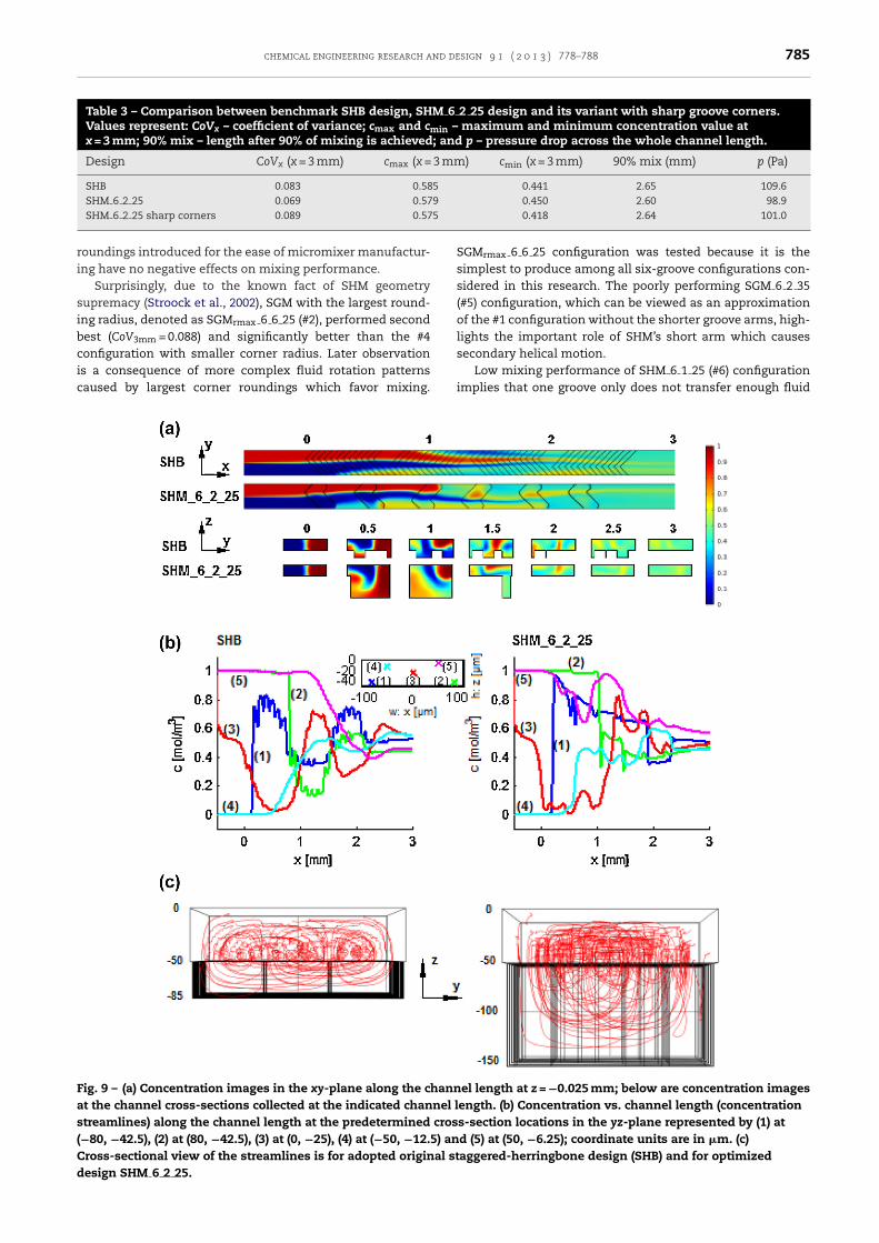
Table 3 – Comparison between benchmark SHB design, SHM 6 2 25 design and its variant with sharp groove corners.Values represent: CoVx – coefficient of variance; cmax and cmin – maximum and minimum concentration value atx = 3 mm; 90% mix – length after 90% of mixing is achieved; and p – pressure drop across the whole channel length.
Design CoVx (x = 3 mm) cmax (x = 3 mm) cmin (x = 3 mm) 90% mix (mm) p (Pa)
SHB 0.083 0.585 0.441 2.65 109.6SHM 6 2 25 0.069 0.579 0.450 2.60 98.9
5
ri
sibcic
Fas(Cd
SHM 6 2 25 sharp corners 0.089 0.57
oundings introduced for the ease of micromixer manufactur-ng have no negative effects on mixing performance.
Surprisingly, due to the known fact of SHM geometryupremacy (Stroock et al., 2002), SGM with the largest round-ng radius, denoted as SGMrmax 6 6 25 (#2), performed secondest (CoV3mm = 0.088) and significantly better than the #4onfiguration with smaller corner radius. Later observation
s a consequence of more complex fluid rotation patternsaused by largest corner roundings which favor mixing.ig. 9 – (a) Concentration images in the xy-plane along the channt the channel cross-sections collected at the indicated channel ltreamlines) along the channel length at the predetermined cros−80, −42.5), (2) at (80, −42.5), (3) at (0, −25), (4) at (−50, −12.5) anross-sectional view of the streamlines is for adopted original stesign SHM 6 2 25.
0.418 2.64 101.0
SGMrmax 6 6 25 configuration was tested because it is thesimplest to produce among all six-groove configurations con-sidered in this research. The poorly performing SGM 6 2 35(#5) configuration, which can be viewed as an approximationof the #1 configuration without the shorter groove arms, high-lights the important role of SHM’s short arm which causessecondary helical motion.
Low mixing performance of SHM 6 1 25 (#6) configurationimplies that one groove only does not transfer enough fluid
el length at z = −0.025 mm; below are concentration imagesength. (b) Concentration vs. channel length (concentrations-section locations in the yz-plane represented by (1) atd (5) at (50, −6.25); coordinate units are in �m. (c)aggered-herringbone design (SHB) and for optimized

786 chemical engineering research and design 9 1 ( 2 0 1 3 ) 778–788
Fig. 10 – Experimental verification of the simulated flow pattern: on the upper part of the figure the dynamics of the waterphases along the channel is presented. The middle part of the figure shows a comparison between simulation results in thexy-plane at z = −25 �m and the photograph taken through the microscope. The course line of the red phase closelyresembles the simulated flow pattern and more detailed comparison is made on the bottom picture. Black/red colorcombination of the column represents the interface of simulated results in the z = −25 �m cut plane and blue/redcombination represents experimental measurements. The interface border was determined via computer image processing.The amplitude of the R and B level of the RGB color scale were processed. (For interpretation of the references to color in this
e art
figure legend, the reader is referred to the web version of thacross the main channel in order to promote stretching andfolding of both fluid phases. The main reason for low efficiencyis the effect of oppositely signed grooves, where the changinggroove shape causes a reverse in directions of vy and vz, whichresults in dissipation of flow pattern caused by the previousgroove similarly observed by Hassell and Zimmerman (2006).
The worst configuration of all tested was SHM 6 6 35 (#7).This is due to the obvious reason of the same orientation ofgrooves throughout the channel, thus the fluid in the shorterarm side remained very poorly mixed. On the other hand, goodmixing is achieved in the longer arm section. This observationsupports the hypothesis of Lynn and Dandy (2007) that thefluid flow within the long arm is the primary mechanism ofmixing.
3.3. Benchmarking against the original SHM design
In order to compare the dynamics of mixing of best performingdesign, namely SHM 6 2 25, against established SHM designs,concentration versus channel length profiles were analyzed,denoted as concentration streamlines, at five predeterminedcross-sectional locations along the channel length. Thismethod of mixing characterization shows insights of dynam-ics of the micromixing process (Du et al., 2010; Zhang et al.,2008). Benchmark geometry was a slightly modified geome-try proposed by Stroock et al. (2002) with the main differencein the main channel cross-section which was fixed to ours(h = 50 �m, w = 200 �m). The benchmark micromixer, denotedas SHB, consisted of four half-cycles of 6 grooves with a groovedepth of 35 �m, groove width of 50 �m and groove ridge lengthof 50 �m (Fig. 9(a)). Positions of the concentration streamlines
and the course of concentrations along the channel are shownin Fig. 9(b). Quantitative indexes show that SHM 6 2 25 designicle.)
performs slightly better compared to SHB design and a 10%reduction of the pressure drop is observed (Table 3).
Concentration streamlines of SHB show typical sinusoidaloscillations with a dominant component which periodicity isdetermined by the length of one full SHM groove cycle anda superimposed smaller sinusoidal wave with periodicity ofone groove/ridge distance (Fig. 9(b), SHB (1)–(3)). Dominantsinusoidal oscillations are a consequence of two transversevortices which alternate with the asymmetry of the herring-bone grooves. Larger oscillation amplitudes suggest a strongermixing effect near grooves. This oscillation pattern is stronglyhindered in the vicinity of the channel rooftop (Fig. 9(b), SHB(4) and (5)) denoting a slower mixing process in the upper partof the channel. Latter observation is especially obvious in thecase of the concentration profile (5), where a significant changein the concentration occurs only after one full groove cycle(∼1.2 mm) meaning that very weak helical flows are presentin that region.
Concentration streamlines of the SHM 6 2 25 designchange abruptly at every groove instance in non-periodicalfashion. It can be observed that the amplitudes of concentra-tion profiles are similar by size to the ones in SHB, occurringat particular grooves indicating a large spatial transfer of fluidphase caused by a single groove in contrast to the SHB wherea series of many grooves achieve similar amplitudes. Sharperprofile transitions from low to high concentration and viceversa correspond to quicker fluid transport across the chan-nel and are associated with a strong mixing effect (Fig. 9(b),SHM 6 2 25 (1)–(3)). The SHM 6 2 25 design exhibits greateractivity of fluid movement near the channel rooftop comparedto SHB which is especially evident from the concentration
streamline (5). After only one groove the concentration profilesignificantly decreases which means that a significant fluid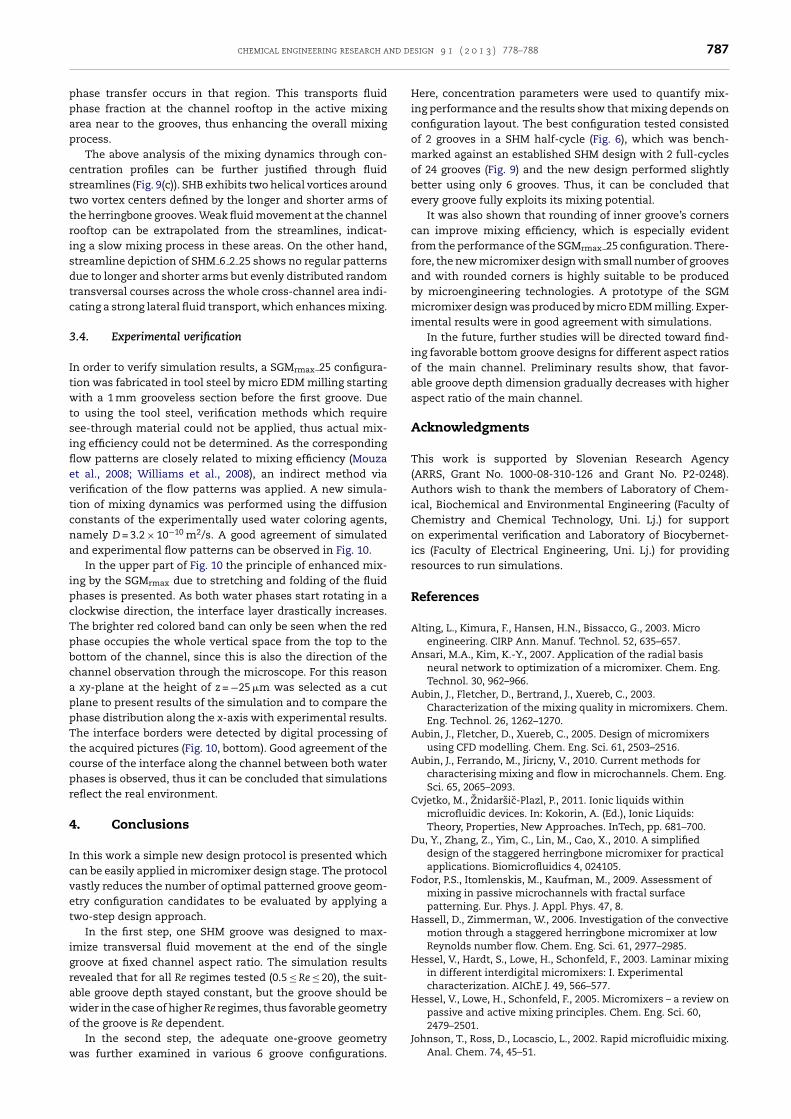
chemical engineering research and design 9 1 ( 2 0 1 3 ) 778–788 787
ppap
csttrisdtc
3
Itwtsiflevtcna
ipcTpbcappTtcpr
4
Icvet
igrawo
w
hase transfer occurs in that region. This transports fluidhase fraction at the channel rooftop in the active mixingrea near to the grooves, thus enhancing the overall mixingrocess.
The above analysis of the mixing dynamics through con-entration profiles can be further justified through fluidtreamlines (Fig. 9(c)). SHB exhibits two helical vortices aroundwo vortex centers defined by the longer and shorter arms ofhe herringbone grooves. Weak fluid movement at the channelooftop can be extrapolated from the streamlines, indicat-ng a slow mixing process in these areas. On the other hand,treamline depiction of SHM 6 2 25 shows no regular patternsue to longer and shorter arms but evenly distributed randomransversal courses across the whole cross-channel area indi-ating a strong lateral fluid transport, which enhances mixing.
.4. Experimental verification
n order to verify simulation results, a SGMrmax 25 configura-ion was fabricated in tool steel by micro EDM milling startingith a 1 mm grooveless section before the first groove. Due
o using the tool steel, verification methods which requireee-through material could not be applied, thus actual mix-ng efficiency could not be determined. As the correspondingow patterns are closely related to mixing efficiency (Mouzat al., 2008; Williams et al., 2008), an indirect method viaerification of the flow patterns was applied. A new simula-ion of mixing dynamics was performed using the diffusiononstants of the experimentally used water coloring agents,amely D = 3.2 × 10⁻¹⁰ m2/s. A good agreement of simulatednd experimental flow patterns can be observed in Fig. 10.
In the upper part of Fig. 10 the principle of enhanced mix-ng by the SGMrmax due to stretching and folding of the fluidhases is presented. As both water phases start rotating in alockwise direction, the interface layer drastically increases.he brighter red colored band can only be seen when the redhase occupies the whole vertical space from the top to theottom of the channel, since this is also the direction of thehannel observation through the microscope. For this reason
xy-plane at the height of z = −25 �m was selected as a cutlane to present results of the simulation and to compare thehase distribution along the x-axis with experimental results.he interface borders were detected by digital processing of
he acquired pictures (Fig. 10, bottom). Good agreement of theourse of the interface along the channel between both waterhases is observed, thus it can be concluded that simulationseflect the real environment.
. Conclusions
n this work a simple new design protocol is presented whichan be easily applied in micromixer design stage. The protocolastly reduces the number of optimal patterned groove geom-try configuration candidates to be evaluated by applying awo-step design approach.
In the first step, one SHM groove was designed to max-mize transversal fluid movement at the end of the singleroove at fixed channel aspect ratio. The simulation resultsevealed that for all Re regimes tested (0.5 ≤ Re ≤ 20), the suit-ble groove depth stayed constant, but the groove should beider in the case of higher Re regimes, thus favorable geometryf the groove is Re dependent.
In the second step, the adequate one-groove geometryas further examined in various 6 groove configurations.
Here, concentration parameters were used to quantify mix-ing performance and the results show that mixing depends onconfiguration layout. The best configuration tested consistedof 2 grooves in a SHM half-cycle (Fig. 6), which was bench-marked against an established SHM design with 2 full-cyclesof 24 grooves (Fig. 9) and the new design performed slightlybetter using only 6 grooves. Thus, it can be concluded thatevery groove fully exploits its mixing potential.
It was also shown that rounding of inner groove’s cornerscan improve mixing efficiency, which is especially evidentfrom the performance of the SGMrmax 25 configuration. There-fore, the new micromixer design with small number of groovesand with rounded corners is highly suitable to be producedby microengineering technologies. A prototype of the SGMmicromixer design was produced by micro EDM milling. Exper-imental results were in good agreement with simulations.
In the future, further studies will be directed toward find-ing favorable bottom groove designs for different aspect ratiosof the main channel. Preliminary results show, that favor-able groove depth dimension gradually decreases with higheraspect ratio of the main channel.
Acknowledgments
This work is supported by Slovenian Research Agency(ARRS, Grant No. 1000-08-310-126 and Grant No. P2-0248).Authors wish to thank the members of Laboratory of Chem-ical, Biochemical and Environmental Engineering (Faculty ofChemistry and Chemical Technology, Uni. Lj.) for supporton experimental verification and Laboratory of Biocybernet-ics (Faculty of Electrical Engineering, Uni. Lj.) for providingresources to run simulations.
References
Alting, L., Kimura, F., Hansen, H.N., Bissacco, G., 2003. Microengineering. CIRP Ann. Manuf. Technol. 52, 635–657.
Ansari, M.A., Kim, K.-Y., 2007. Application of the radial basisneural network to optimization of a micromixer. Chem. Eng.Technol. 30, 962–966.
Aubin, J., Fletcher, D., Bertrand, J., Xuereb, C., 2003.Characterization of the mixing quality in micromixers. Chem.Eng. Technol. 26, 1262–1270.
Aubin, J., Fletcher, D., Xuereb, C., 2005. Design of micromixersusing CFD modelling. Chem. Eng. Sci. 61, 2503–2516.
Aubin, J., Ferrando, M., Jiricny, V., 2010. Current methods forcharacterising mixing and flow in microchannels. Chem. Eng.Sci. 65, 2065–2093.
Cvjetko, M., Znidarsic-Plazl, P., 2011. Ionic liquids withinmicrofluidic devices. In: Kokorin, A. (Ed.), Ionic Liquids:Theory, Properties, New Approaches. InTech, pp. 681–700.
Du, Y., Zhang, Z., Yim, C., Lin, M., Cao, X., 2010. A simplifieddesign of the staggered herringbone micromixer for practicalapplications. Biomicrofluidics 4, 024105.
Fodor, P.S., Itomlenskis, M., Kaufman, M., 2009. Assessment ofmixing in passive microchannels with fractal surfacepatterning. Eur. Phys. J. Appl. Phys. 47, 8.
Hassell, D., Zimmerman, W., 2006. Investigation of the convectivemotion through a staggered herringbone micromixer at lowReynolds number flow. Chem. Eng. Sci. 61, 2977–2985.
Hessel, V., Hardt, S., Lowe, H., Schonfeld, F., 2003. Laminar mixingin different interdigital micromixers: I. Experimentalcharacterization. AIChE J. 49, 566–577.
Hessel, V., Lowe, H., Schonfeld, F., 2005. Micromixers – a review onpassive and active mixing principles. Chem. Eng. Sci. 60,2479–2501.
Johnson, T., Ross, D., Locascio, L., 2002. Rapid microfluidic mixing.Anal. Chem. 74, 45–51.

788 chemical engineering research and design 9 1 ( 2 0 1 3 ) 778–788
studies on lipase-catalyzed isoamyl acetate synthesis in a
Kee, S., Gavriilidis, A., 2008. Design and characterisation of thestaggered herringbone mixer. Chem. Eng. J. 142, 109–121.
Kim, D., Lee, S., Kwon, T., Lee, S., 2004. A barrier embeddedchaotic micromixer. J. Micromech. Microeng. 14, 798–805.
Kukuková, A., Noël, B., Kresta, S.M., Aubin, J., 2008. Impact ofsampling method and scale on the measurement of mixingand the coefficient of variance. AIChE J. 54, 3068–3083.
Lynn, N., Dandy, D., 2007. Geometrical optimization of helicalflow in grooved micromixers. Lab Chip 7, 580–587.
Mouza, A.A., Patsa, C.-M., Schönfeld, F., 2008. Mixing performanceof a chaotic micro-mixer. Chem. Eng. Res. Des. 86, 1128–1134.
Nguyen, N.-T., Wu, Z., 2005. Micromixers – a review. J. Micromech.Microeng. 15, R1–R16.
Novak, U., Pohar, A., Plazl, I., Znidarsic-Plazl, P., 2012. Ionicliquid-based aqueous two-phase extraction within amicrochannel system. Sep. Purif. Technol. 97, 172–178.
Pohar, A., Plazl, I., 2009. Process intensification throughmicroreactor application. Chem. Biochem. Eng. Q 23, 537–544.
Sato, Yagyu, D., Ito, S., Shoji, S., 2006. Improved inclinedmulti-lithography using water as exposure medium and its 3Dmixing microchannel application. Sensor. Actuators A: Phys.128, 183–190.
Song, H., Yin, X., Bennett, D., 2008. Optimization analysis of the
staggered herringbone micromixer based on the slip-drivenmethod. Chem. Eng. Res. Des. 86, 883–891.Squires, T., Quake, S., 2005. Microfluidics: fluid physics at thenanoliter scale. Rev. Mod. Phys. 77, 977–1026.
Stroock, A., Dertinger, S., Ajdari, A., Mezic, I., Stone, H.,Whitesides, G., 2002. Chaotic mixer for microchannels.Science 25, 647–651.
Stroock, A., McGraw, G., 2004. Investigation of the staggeredherringbone mixer with a simple analytical model. Philos.Trans. R. Soc. A 362, 971–986.
Tofteberg, T., Skolimowski, M., Andreassen, E., Geschke, O., 2010.A novel passive micromixer: lamination in a planar channelsystem. Microfluid. Nanofluid. 8, 209–215.
Wang, H., Iovenitti, P., Harvey, E., Masood, S., 2003. Numericalinvestigation of mixing in microchannels with patternedgrooves. J. Micromech. Microeng. 13, 801–808.
Williams, M., Longmuir, K., Yager, P., 2008. A practical guide to thestaggered herringbone mixer. Lab Chip 8, 1121–1129.
Yang, J., Huang, K., Lin, Y., 2005. Geometric effects on fluid mixingin passive grooved micromixers. Lab Chip 5, 1140–1147.
Zhang, Z., Yim, C., Lin, M., Cao, X., 2008. Quantitativecharacterization of micromixing simulation. Biomicrofluidics2, 014101.
Znidarsic-Plazl, P., Plazl, I., 2009. Modelling and experimental
microreactor. Process Biochem. 44, 1115–1121.
Related Documents


