SS-DC96VE www.daikincomfort.com 12/21 Supersedes 09/21 DC96VE Two-Stage, Multi-Speed ECM Gas Furnace Up to 96% AFUE Heating Input: 40,000 - 100,000 BTU/h ■ Contents Nomenclature........................................ 2 Product Specificaons ........................... 3 Dimensions ............................................ 4 Airflow Specificaons ............................ 5 Wiring Diagram.................................... 10 Accessories .......................................... 11 ■ Standard Features • Energy-efficient mul-speed ECM blower motor • Heavy-duty stainless-steel tubular heat exchanger • Stainless-steel secondary heat exchanger • Two-stage gas valve provides quiet, economical heang • Durable Silicon Nitride igniter • Quiet two-speed induced draſt blower • Self-diagnosc control board with constant memory fault code history output to a LED • Color-coded low-voltage terminals with provi- sions for electronic air cleaner and humidifier • Low connuous fan speed opons offer quiet air circulaon • Can no longer be installed in California’s South Coast Air Quality Management District (SCAQMD) on or aſter October 1, 2019 • AHRI Cerfied; ETL Listed ■ Cabinet Features • Designed for mul-posion installaon: DC96VE: Counter flow, horizontal leſt or right • Cerfied for direct vent (2-pipe) or non-direct vent (1-pipe) • Easy-to-install top venng with oponal side venng • Convenient leſt or right connecon for gas and electrical service • Cabinet air leakage (Q Leak ) ≤ 2% • Heavy-gauge steel cabinet with durable finish • Fully insulated heat exchanger and blower secon • Airght solid boom or side return with easy-cut tabs for effortless removal in boom air-inlet applicaons * Complete warranty details available from your local dealer or at www.daikincomfort.com. To receive the Lifeme Heat Exchanger Limited Warranty (good for as long as you own your home), the 6-Year Unit Replacement Limited Warranty and the 12-Year Parts Limited Warranty, online registraon must be completed within 60 days of installaon. Addional requirements for annual maintenance are required for the Unit Replacement Limited Warranty. Online registraon and some of the addional requirements are not required in California or Quebec.

Welcome message from author
This document is posted to help you gain knowledge. Please leave a comment to let me know what you think about it! Share it to your friends and learn new things together.
Transcript

SS-DC96VE www.daikincomfort.com 12/21Supersedes 09/21
DC96VE
Two-Stage, Multi-Speed ECM Gas Furnace
Up to 96% AFUEHeating Input: 40,000 - 100,000 BTU/h
■ ContentsNomenclature ........................................ 2Product Specifications ........................... 3Dimensions ............................................ 4Airflow Specifications ............................ 5Wiring Diagram .................................... 10Accessories .......................................... 11
■ Standard Features• Energy-efficient multi-speed ECM blower motor• Heavy-duty stainless-steel
tubular heat exchanger • Stainless-steel secondary heat exchanger• Two-stage gas valve provides quiet,
economical heating • Durable Silicon Nitride igniter• Quiet two-speed induced draft blower• Self-diagnostic control board with constant
memory fault code history output to a LED• Color-coded low-voltage terminals with provi-
sions for electronic air cleaner and humidifier• Low continuous fan speed options
offer quiet air circulation• Can no longer be installed in California’s
South Coast Air Quality Management District (SCAQMD) on or after October 1, 2019
• AHRI Certified; ETL Listed
■ Cabinet Features• Designed for multi-position installation:
DC96VE: Counter flow, horizontal left or right• Certified for direct vent (2-pipe) or non-direct vent (1-pipe) • Easy-to-install top venting with optional side venting• Convenient left or right connection
for gas and electrical service• Cabinet air leakage (QLeak) ≤ 2% • Heavy-gauge steel cabinet with durable finish• Fully insulated heat exchanger and blower section• Airtight solid bottom or side return
with easy-cut tabs for effortless removal in bottom air-inlet applications
* Complete warranty details available from your local dealer or at www.daikincomfort.com. To receive the Lifetime Heat Exchanger Limited Warranty (good for as long as you own your home), the 6-Year Unit Replacement Limited Warranty and the 12-Year Parts Limited Warranty, online registration must be completed within 60 days of installation. Additional requirements for annual maintenance are required for the Unit Replacement Limited Warranty. Online registration and some of the additional requirements are not required in California or Quebec.

2 www.daikincomfort.com SS-DC96VE SS-DC96VE www.daikincomfort.com 3
D C 96 V E 060 3 B N A A1 2 3,4 5 6 7,8,9 10 11 12 13 14
Brand Minor RevisionD -‐ Daikin Brand A -‐ Initial Release
B -‐ 1st RevisionConfigurationM -‐ Upflow/Horizontal Major RevisionC -‐ Downflow/Horizontal A -‐ Initial Release
B -‐ 1st RevisionAFUE97 – 97-‐98% AFUE 92 -‐ 92% AFUE NOx96 – 96% AFUE N -‐ Low Nox (40ng/J)
Gas Valve Cabinet WidthM -‐ Modulating H -‐ Convertible Two-‐Stage B -‐ 17½"V -‐ Two Stage S -‐ Single Stage C -‐ 21"
D -‐ 24½"MotorC Variable Speed ECM / Communicating Maximum CFME - Multi-Speed ECM S - Multi-Speed PSC 2 -‐ 800 CFM
3 -‐ 1200 CFMMBTU/h 4 -‐ 1600 CFM040 -‐ 40,000 BTU/h 100 -‐ 100,000 BTU/h 5 -‐ 2000 CFM060 -‐ 60,000 BTU/h 120 -‐ 120,000 BTU/h080 -‐ 80,000 BTU/h
Nomenclature

2 www.daikincomfort.com SS-DC96VE SS-DC96VE www.daikincomfort.com 3
Product Specifications
DC96VE 0403BNA
DC96VE 0603BNA
DC96VE 0803BNA
DC96VE 1005CNA
Heating Data
High Fire Input¹ 40,000 60,000 80,000 100,000
High Fire Output¹ 38,400 57,600 76,800 96,000
Low-Fire Steady-State Input¹ 28,000 42,000 56,000 70,000
Low-Fire Steady-State Output¹ 26,880 40,320 53,760 67,200
AFUE² 96 96 96 96
Temperature Rise Range (°F) 25 - 55 25 - 55 40 - 70 35 - 65
Vent Diameter³ 2" - 3" 2" - 3" 2" - 3" 2" - 3"
No. of Burners 2 3 4 5
Circulator Blower
Available AC @ 0.5” ESP 1.5 - 3 1.5 - 3 1.5 - 3 4 - 5
Size (D x W) 10" x 8" 11" x 8" 11" x 8" 11" x 10"
Horsepower @ 1075 RPM 1/2 1/2 1/2 1
No. of speeds 5 5 5 5
Electrical Data
Min. Circuit Ampacity4 8 8 8 13.3
Max. Overcurrent Device (amps)5 15 15 15 15
Shipping Weight (lbs) 112 115 118 140
¹ Natural Gas BTU/h; for altitudes 0-4500'’ above sea level, reduce input rating by 4% for each 1000' above 4500' altitude.² DOE AFUE based upon Isolated Combustion System (ICS)³ Vent and combustion air diameters may vary depending upon vent length. Refer to the latest editions of the National Fuel Gas Code NFPA
54/ANSI Z223.1 (in the USA) and the Canada National Standard of Canada, CAN/CSA B149.1 and CAN/CSA B142.2 (in Canada).⁴ Minimum Circuit Ampacity = (1.25 x Circulator Blower Amps) + ID Blower amps. Wire size should be determined in accordance with
National Electrical Codes. Extensive wire runs will require larger wire sizes.⁵ Maximum Overcurrent Protection Device refers to maximum recommended fuse or circuit breaker size. May use fuses or HACR-type
circuit breakers of the same size as noted.
Notes• All furnaces are manufactured for use on 115 VAC, 60 Hz, single-phase electrical supply.• Gas Service Connection ½" FPT• Important: Size fuses and wires properly and make electrical connections in accordance with the National
Electrical Code and/or all existing local codes.
4 www.daikincomfort.com SS-DC96VE SS-DC96VE www.daikincomfort.com 5
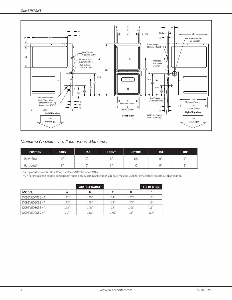
Dimensions
Minimum Clearances to Combustible Materials
Position Sides Rear Front Bottom Flue Top
Downflow 0" 0" 3" NC 0" 1"
Horizontal 6" 0" 3" C 0" 6"
C = If placed on combustible floor, the floor MUST be wood ONLY.NC = For installation on non-combustible floors only. A combustible floor sub-base must be used for installations on combustible flooring.
A
34½
4⅛
11⅜
14¾
25⅛
28¾
C
6⅞ 6⅞
11⅜
14⅞
14¾
25⅛
3½ 2½
2
1⅞
2⅝
23
14
1⅜
1½
1⅝
E
DUnfolded Flanges
18⅛Unfolded Flanges
20⅛Folded Flanges
2⅝
1⅞
2½
6½
2
Front ViewRight-Side View
Low-VoltageElectrical Outlet
Alternate Gas
High-VoltageElectrical Outlet
Standard Drain TrapDrain Trap Holes
Alternate Gas Supply
Alternate Vent/
High-Voltage Electrical Outlet
Right Side ExteriorDrain Trap Holes
Low-Voltage Electrical Outlet
AirDischarge
AirDischarge
Folded Flanges
B
18¼
AIR DISCHARGE AIR RETURN
MODEL A B C D E
DC96VE0403BNA 17½" 14⅝" 14" 14½" 16"
DC96VE0603BNA 17½" 14⅝" 14" 14½" 16"
DC96VE0803BNA 17½" 14⅝" 14" 14½" 16"
DC96VE1005CNA 21"” 18⅛" 17½" 18" 19½"

4 www.daikincomfort.com SS-DC96VE SS-DC96VE www.daikincomfort.com 5
Minimum Filter Sizes
DC96VE 0403BN*
DC96VE 0603BN*
DC96VE 0803BN*
DC96VE 1005CN*
Filter Size (in²) (Qty) (2) 10 x 10 or (1) 16 x 25 (Top Return)
Note: Other size filters of equal or greater dimensions may be used. Filters may also be centrally located.
Airflow Data — DC96VE0403BNA
COOLING
DIP Switches S1-1 S1-2 S1-3
Static 0.1 0.2 0.3 0.4 0.5 0.6 0.7 0.8
Tstat Call CFM CFM CFM CFM CFM CFM CFM CFM
**OFF OFF OFFYlo 647 576 511 449 387 335 280 252Y 1229 1181 1150 1117 1078 1035 1002 964
ON OFF OFFYlo 1137 1096 1056 1018 981 940 897 859Y 647 576 511 449 387 335 280 252
ON ON OFFYlo 1137 1096 1056 1018 981 940 897 859Y 1229 1181 1150 1117 1078 1035 1002 964
OFF ON OFF^Ylo 647 576 511 449 387 335 280 252Y 743 688 628 572 515 459 408 364
OFF OFF ON^Ylo 647 576 511 449 387 335 280 252Y 939 894 846 806 759 706 661 614
OFF ON ON^Ylo 1137 1096 1056 1018 981 940 897 859Y 743 688 628 572 515 459 408 364
ON OFF ONYlo 939 894 846 806 759 706 661 614Y 1229 1181 1150 1117 1078 1035 1002 964
ON ON ON^ Ylo 939 894 846 806 759 706 661 614Y 1137 1096 1056 1018 981 940 897 859
** Factory Default SINGLE STAGE COOLING^ *NOT RECOMMENDED
CONTINUOUS FAN
DIP Switches S2-2 S2-3 S2-4
Static 0.1 0.2 0.3 0.4 0.5 0.6 0.7 0.8
Tstat Call CFM CFM CFM CFM CFM CFM CFM CFM
**OFF OFF OFF G 743 688 628 572 515 459 408 364
ON OFF OFF G 939 894 846 806 759 706 661 614
ON ON OFF G 1137 1096 1056 1018 981 940 897 859
OFF ON OFF G 647 576 511 449 387 335 280 252
OFF OFF ON G 1229 1181 1150 1117 1078 1035 1002 964
OFF ON ON G 743 688 628 572 515 459 408 364
ON OFF ON G 743 688 628 572 515 459 408 364
ON ON ON G 743 688 628 572 515 459 408 364
HEATING
DIP Switches S1-4 S2-1
Static 0.1 0.2 0.3 0.4 0.5 0.6 0.7 0.8
Tstat Call CFM Rise CFM Rise CFM Rise CFM Rise CFM Rise CFM CFM CFM
**OFF OFFW1 743 33 688 36 628 40 572 44 515 48 459 408 364W2 939 38 894 40 846 42 806 44 759 47 706 661 614
ON OFFW1 1137 NA 1096 NA 1056 NA 1018 NA 981 N/A 940 897 859W2 939 38 894 40 846 42 806 44 759 47 706 661 614
ON ONW1 1137 NA 1096 NA 1056 NA 1018 NA 981 N/A 940 897 859W2 647 55 576 NA 511 NA 449 NA 387 NA NA NA NA
OFF ONW1 647 38 576 43 511 49 449 55 387 64 335 280 252W2 1229 29 1181 30 1150 31 1117 32 1078 33 1035 1002 964
** Factory Default SINGLE STAGE COOLING^ *NOT RECOMMENDED
Notes• All furnaces ship as high speed for cooling. Installer must adjust blower speed as needed.• For most jobs, about 400 CFM per ton when cooling is desirable.• INSTALLATION IS TO BE ADJUSTED TO OBTAIN TEMPERATURE RISE WITHIN THE RANGE SPECIFIED ON THE RATING PLATE.
6 www.daikincomfort.com SS-DC96VE SS-DC96VE www.daikincomfort.com 7
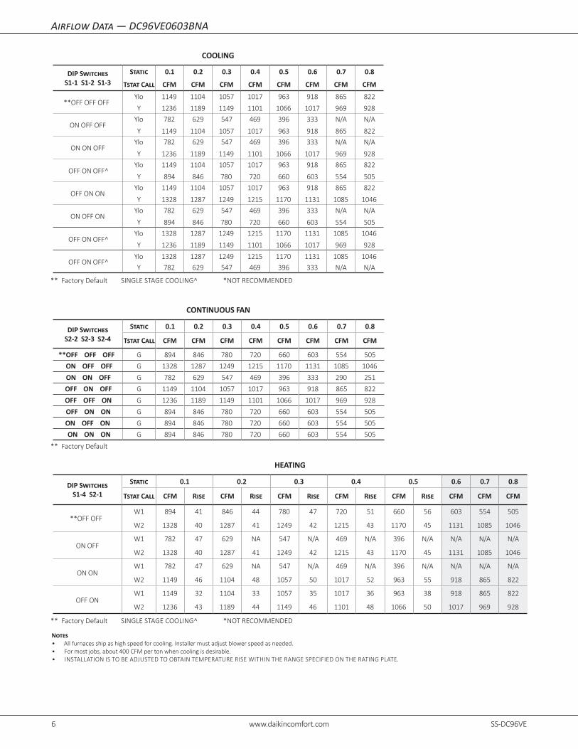
Airflow Data — DC96VE0603BNA
Notes• All furnaces ship as high speed for cooling. Installer must adjust blower speed as needed.• For most jobs, about 400 CFM per ton when cooling is desirable.• INSTALLATION IS TO BE ADJUSTED TO OBTAIN TEMPERATURE RISE WITHIN THE RANGE SPECIFIED ON THE RATING PLATE.
COOLING
DIP Switches S1-1 S1-2 S1-3
Static 0.1 0.2 0.3 0.4 0.5 0.6 0.7 0.8
Tstat Call CFM CFM CFM CFM CFM CFM CFM CFM
**OFF OFF OFFYlo 1149 1104 1057 1017 963 918 865 822
Y 1236 1189 1149 1101 1066 1017 969 928
ON OFF OFFYlo 782 629 547 469 396 333 N/A N/A
Y 1149 1104 1057 1017 963 918 865 822
ON ON OFFYlo 782 629 547 469 396 333 N/A N/A
Y 1236 1189 1149 1101 1066 1017 969 928
OFF ON OFF^Ylo 1149 1104 1057 1017 963 918 865 822
Y 894 846 780 720 660 603 554 505
OFF ON ONYlo 1149 1104 1057 1017 963 918 865 822
Y 1328 1287 1249 1215 1170 1131 1085 1046
ON OFF ONYlo 782 629 547 469 396 333 N/A N/A
Y 894 846 780 720 660 603 554 505
OFF ON OFF^Ylo 1328 1287 1249 1215 1170 1131 1085 1046
Y 1236 1189 1149 1101 1066 1017 969 928
OFF ON OFF^Ylo 1328 1287 1249 1215 1170 1131 1085 1046
Y 782 629 547 469 396 333 N/A N/A
** Factory Default SINGLE STAGE COOLING^ *NOT RECOMMENDED
CONTINUOUS FAN
DIP Switches S2-2 S2-3 S2-4
Static 0.1 0.2 0.3 0.4 0.5 0.6 0.7 0.8
Tstat Call CFM CFM CFM CFM CFM CFM CFM CFM
**OFF OFF OFF G 894 846 780 720 660 603 554 505
ON OFF OFF G 1328 1287 1249 1215 1170 1131 1085 1046
ON ON OFF G 782 629 547 469 396 333 290 251
OFF ON OFF G 1149 1104 1057 1017 963 918 865 822
OFF OFF ON G 1236 1189 1149 1101 1066 1017 969 928
OFF ON ON G 894 846 780 720 660 603 554 505
ON OFF ON G 894 846 780 720 660 603 554 505
ON ON ON G 894 846 780 720 660 603 554 505
** Factory Default
HEATING
DIP Switches S1-4 S2-1
Static 0.1 0.2 0.3 0.4 0.5 0.6 0.7 0.8
Tstat Call CFM Rise CFM Rise CFM Rise CFM Rise CFM Rise CFM CFM CFM
**OFF OFFW1 894 41 846 44 780 47 720 51 660 56 603 554 505
W2 1328 40 1287 41 1249 42 1215 43 1170 45 1131 1085 1046
ON OFFW1 782 47 629 NA 547 N/A 469 N/A 396 N/A N/A N/A N/A
W2 1328 40 1287 41 1249 42 1215 43 1170 45 1131 1085 1046
ON ONW1 782 47 629 NA 547 N/A 469 N/A 396 N/A N/A N/A N/A
W2 1149 46 1104 48 1057 50 1017 52 963 55 918 865 822
OFF ONW1 1149 32 1104 33 1057 35 1017 36 963 38 918 865 822
W2 1236 43 1189 44 1149 46 1101 48 1066 50 1017 969 928
** Factory Default SINGLE STAGE COOLING^ *NOT RECOMMENDED

6 www.daikincomfort.com SS-DC96VE SS-DC96VE www.daikincomfort.com 7
Notes• All furnaces ship as high speed for cooling. Installer must adjust blower speed as needed.• For most jobs, about 400 CFM per ton when cooling is desirable.• INSTALLATION IS TO BE ADJUSTED TO OBTAIN TEMPERATURE RISE WITHIN THE RANGE SPECIFIED ON THE RATING PLATE.
Airflow Data — DC96VE0803BNA
COOLING
DIP Switches S1-1 S1-2 S1-3
Static 0.1 0.2 0.3 0.4 0.5 0.6 0.7 0.8
Tstat Call CFM CFM CFM CFM CFM CFM CFM CFM
**OFF OFF OFFYlo 894 842 784 726 682 618 562 519
Y 1111 1068 1025 984 941 885 860 801
ON OFF OFFYlo 750 644 569 507 442 388 328 N/A
Y 894 842 784 726 682 618 562 519
ON ON OFFYlo 750 644 569 507 442 388 328 N/A
Y 1111 1068 1025 984 941 885 860 801
OFF ON OFFYlo 894 842 784 726 682 618 562 519
Y 1221 1172 1128 1087 1049 1005 959 922
OFF ON ONYlo 894 842 784 726 682 618 562 519
Y 1311 1293 1249 1203 1172 1122 1088 1041
ON OFF ONYlo 750 644 569 507 442 388 328 N/A
Y 1221 1172 1128 1087 1049 1005 959 922
OFF ON OFF^Ylo 1311 1293 1249 1203 1172 1122 1088 1041
Y 1111 1068 1025 984 941 885 860 801
OFF ON OFF^Ylo 1311 1293 1249 1203 1172 1122 1088 1041
Y 750 644 569 507 442 388 328 N/A
** Factory Default SINGLE STAGE COOLING^ *NOT RECOMMENDED
CONTINUOUS FAN
DIP Switches S2-2 S2-3 S2-4
Static 0.1 0.2 0.3 0.4 0.5 0.6 0.7 0.8
Tstat Call CFM CFM CFM CFM CFM CFM CFM CFM
**OFF OFF OFF G 1221 1172 1128 1087 1049 1005 959 922
ON OFF OFF G 1311 1293 1249 1203 1172 1122 1088 1041
ON ON OFF G 750 644 569 507 442 388 328 288
OFF ON OFF G 894 842 784 726 682 618 562 519
OFF OFF ON G 1111 1068 1025 984 941 885 860 801
OFF ON ON G 1221 1172 1128 1087 1049 1005 959 922
ON OFF ON G 1221 1172 1128 1087 1049 1005 959 922
ON ON ON G 1221 1172 1128 1087 1049 1005 959 922
** Factory Default
HEATING
DIP Switches S1-4 S2-1
Static 0.1 0.2 0.3 0.4 0.5 0.6 0.7 0.8
Tstat Call CFM Rise CFM Rise CFM Rise CFM Rise CFM Rise CFM CFM CFM
**OFF OFFW1 1221 40 1172 42 1128 44 1087 45 1049 47 1005 959 922
W2 1311 54 1293 54 1249 56 1203 58 1172 60 1122 1088 1041
ON OFFW1 750 66 644 N/A 569 N/A 507 N/A 442 N/A 388 328 N/A
W2 1311 54 1293 54 1249 56 1203 58 1172 60 1122 1088 1041
ON ONW1 750 NA 644 N/A 569 N/A 507 N/A 442 N/A 388 328 N/A
W2 894 N/A 842 N/A 784 N/A 726 N/A 682 N/A 618 562 519
OFF ONW1 894 55 842 59 784 NA 726 NA 682 N/A 618 562 519
W2 1111 63 1068 66 1025 69 984 NA 941 NA 885 N/A 801
** Factory Default SINGLE STAGE COOLING^ *NOT RECOMMENDED

8 www.daikincomfort.com SS-DC96VE SS-DC96VE www.daikincomfort.com 9
Airflow Data — DC96VE1005CNA
Notes• All furnaces ship as high speed for cooling. Installer must adjust blower speed as needed.• For most jobs, about 400 CFM per ton when cooling is desirable.• INSTALLATION IS TO BE ADJUSTED TO OBTAIN TEMPERATURE RISE WITHIN THE RANGE SPECIFIED ON THE RATING PLATE.
COOLING
DIP Switches S1-1 S1-2 S1-3
Static 0.1 0.2 0.3 0.4 0.5 0.6 0.7 0.8
Tstat Call CFM CFM CFM CFM CFM CFM CFM CFM
**OFF OFF OFF Ylo 1637 1577 1528 1467 1410 1369 1307 1256
Y 2069 2009 1978 1932 1923 1876 1834 1773
ON OFF OFFYlo 1477 1422 1364 1301 1244 1190 1135 1078
Y 1637 1577 1528 1467 1410 1369 1307 1256
ON ON OFFYlo 1477 1422 1364 1301 1244 1190 1135 1078
Y 2069 2009 1978 1932 1923 1876 1834 1773
OFF ON OFF^Ylo 1637 1577 1528 1467 1410 1369 1307 1256
Y 1300 1234 1175 1109 1052 992 928 866
OFF ON ONYlo 1637 1577 1528 1467 1410 1369 1307 1256
Y 1866 1817 1774 1729 1684 1637 1593 1552
ON OFF ONYlo 1477 1422 1364 1301 1244 1190 1135 1078
Y 1300 1234 1175 1109 1052 992 928 866
OFF ON OFF^Ylo 1866 1817 1774 1729 1684 1637 1593 1552
Y 2069 2009 1978 1932 1923 1876 1834 1773
OFF ON OFF^Ylo 1866 1817 1774 1729 1684 1637 1593 1552
Y 1477 1422 1364 1301 1244 1190 1135 1078
** Factory Default SINGLE STAGE COOLING^ *NOT RECOMMENDED
CONTINUOUS FAN
DIP Switches S2-2 S2-3 S2-4
Static 0.1 0.2 0.3 0.4 0.5 0.6 0.7 0.8
Tstat Call CFM CFM CFM CFM CFM CFM CFM CFM
**OFF OFF OFF G 1300 1234 1175 1109 1052 992 928 866
ON OFF OFF G 1866 1817 1774 1729 1684 1637 1593 1552
ON ON OFF G 1477 1422 1364 1301 1244 1190 1135 1078
OFF ON OFF G 1637 1577 1528 1467 1410 1369 1307 1256
OFF OFF ON G 2069 2009 1978 1932 1923 1876 1834 1773
OFF ON ON G 1300 1234 1175 1109 1052 992 928 866
ON OFF ON G 1300 1234 1175 1109 1052 992 928 866
ON ON ON G 1300 1234 1175 1109 1052 992 928 866
** Factory Default
HEATING
DIP Switches S1-4 S2-1
Static 0.1 0.2 0.3 0.4 0.5 0.6 0.7 0.8
Tstat Call CFM Rise CFM Rise CFM Rise CFM Rise CFM Rise CFM CFM CFM
**OFF OFFW1 1300 47 1234 50 1175 52 1109 56 1052 59 992 928 866
W2 1866 47 1817 48 1774 50 1729 51 1684 52 1637 1593 1552
ON OFFW1 1477 42 1422 43 1364 45 1301 47 1244 49 1190 1135 1078
W2 1866 47 1817 48 1774 50 1729 51 1684 52 1637 1593 1552
ON ONW1 1477 42 1422 43 1364 45 1301 47 1244 49 1190 1135 1078
W2 1637 54 1577 56 1528 58 1467 60 1410 62 1369 1307 1256
OFF ONW1 1637 38 1577 39 1528 40 1467 42 1410 44 1369 1307 1256
W2 2069 43 2009 44 1978 44 1932 46 1923 46 1876 1834 1773
** Factory Default SINGLE STAGE COOLING^ *NOT RECOMMENDED

8 www.daikincomfort.com SS-DC96VE SS-DC96VE www.daikincomfort.com 9
Temperature Rise Range Chart
3040
5060
7080
9011
012
010
013
014
015
0
100
90 80 70 60 50 40 30 20 10
OU
TPU
TB
TU/H
Rx
1000
BTU
OU
TPU
Tvs
TEM
PE
RAT
UR
ER
ISE
CH
AR
TTEMPERATURERISE
600
CFM
700
900 10
00 1100 12
00
1400
1600 18
00 2000 22
00 2400
CFM
FOR
MU
LAS
BTU
OU
TPU
T=
CFM
x1.
08x
RIS
E
RIS
E=
BTU
OU
TPU
T1.
08÷
CFM
800
Temperature Rise
Ou
tpu
t BT
U/h
x 1
,000
Form
ulas
BTU
/h O
utpu
t = C
FM x
1.0
8 x
Rise
Rise
=
BTU
/H O
utpu
t
CFM
x 1
.08
BTU
Ou
tpu
t Vs
. Tem
pera
ture
Ris
e Ch
art

10 www.daikincomfort.com SS-DC96VE SS-DC96VE www.daikincomfort.com 11
Wiring Diagram — DC96VE
Wiri
ng i
s su
bjec
t to
cha
nge.
Alw
ays
refe
r to
the
wiri
ng d
iagr
am o
n th
e un
it fo
r th
e m
ost
up-t
o-da
te w
iring
.⚠
War
ning
Hig
h Vo
ltage
: D
isco
nnec
t al
l po
wer
bef
ore
serv
icin
g or
ins
talli
ng t
his
unit.
Mul
tiple
pow
er
sour
ces
may
be
pres
ent.
Failu
re to
do
so m
ay c
ause
pro
pert
y da
mag
e, p
erso
nal i
njur
y, o
r de
ath.⚡
GN
GND
COLOR CODES:
GN GREEN
RD REDGY GRAY
PU PURPLE
PK PINK
BK BLACK
BL BLUEWH WHITEBR BROWN
YL YELLOWOR ORANGE
GND
BK
RD
GNGN
24VAC
115VAC
GND
GRD
BK
YLO Y W1 W2 R G C TWINN.E.C. CLASS 2 WIRE
0140F02481-A
BRPK
GY
OR
GNBL
YL
S1
BK
HUMX-FMRL1
CIRC-HEAC-H
5
21
43
24 V 3 AFUSE
NEUTRAL
DIAGNOSTIC
LED'S
5 CIRCUIT CONNECTOR
10
63
4
52
7
11
1
12
8
9
FRONT COVERPRESSURESWITCH
NOC
FUSE 3 A
MICROTO
PS2 (2)
TR (9)
G
HI
C
TH (5)
24V THERMOSTAT CONNECTIONS N.E.C. CLASS 2 WIRE
VALVEGAS
W2
TRANSFORMER
HLI (6)
Y2
Y1 HLO (11)
GND (4)
O
MVL (7)
NO
W1
C
R
CONTROLSAUTO RESET AUXILIARY LIMIT
LIMIT CONTROLSMANUAL RESET ROLLOUTPRESS. SWTICH
HIGH FIRE
C
SWITCHLOW FIRE PRESS
MVH (1)
DEHUM
GND
PS1 (12)
LIMIT CONTROLAUTO RESET PRIMARY24 VAC
NO
PM
MVC (8)
INTEGRATED CONTROL MODULE
C
BLWR
AIRINDOOR
CIRCULATOR
RTO
MICROTO
TO+VDC
EAC
HUMIDIFIER
ID
NEUTRAL
WIRING TO UNIT
L
INTEGRATED CONTROL MODULE
HOT SURFACE
GND
BLWR
NEUTRAL
WARNING:
GROUNDED.
OVERCURRENT PROTECTION DEVICE
MUST BE PROPERLY
SWITCH
NEUTRAL
ELECTRONIC
AIR
IGN
IND HI
DISCONNECT
FS
POLARIZED AND
NEUTRAL
LINE
NEUTRAL
JUNCTION BOX
BLWRIND LO
N
INDOOR
AIR CLEANER
HUM
DOOR
NEUTRAL
INTEGRATED CONTROL MODULE
TO 115VAC/ 1Ø /60 HZ POWER SUPPLY WITH
115 VAC
HUM-OUT
IGNITER
CIRCULATOR
BEFORE SERVICING.
FLAME SENSOR
DISCONNECT POWER
LINE
GND
T1 T2
ORBR
BK WH
WH
WH
WH
PU GYYL
ORBR
PK
RDW
H BK
PU
GY
BR
OR
RD
OR
BL
RDW
HW
HLINE
NO
LIMIT CONTROLAUXILIARYAUTO RESET
PK
WARNING:DISCONNECT
TRANSFORMER40 VA
PU
GY
NNO
G
C
SWITCHPRESSURELOW FIRE
SENSORFLAME
PRESSURE SWITCHFRONT COVER
C TO UNIT MUST BE
BL
RD
AND GROUNDED.
1
JUNCTION BOX
WH
SWITCH (PRESS.)
FIELD SPLICEFIELD GND
3
GNBL
BR
WH
NO
LIMIT CONTROLAUTO RESET PRIMARY
WH
1
OR
30 kBTU AND 40 kBTU)CONTROLS (SINGLE CONTROL ON
MANUAL RESET ROLLOUT LIMIT
WH
L
PU
GY
BK
SWITCH ASSEMBLYID BLOWER TWO-STAGE PRESSURE
OR
WH
SERVICING. WIRING
EQUIPMENT GND
INTERNAL TO
SWITCHPRESSUREHIGH FIRE
PROT. DEVICE
INTEGRATED CONTROL
PK
PU
PLUG CONNECTION
L
N
BK
C
DOOR OPEN)(OPEN WHENDOOR SWITCHCOMPARTMENTBLOWER
SWITCH (TEMP.)
GND
1
BLOWERCIRCULATOR
JUNCTION
OR
40 VA
Ø /60 HZ
DISCONNECT
(WHITE RODGERS)GAS VALVETWO STAGE
OVERCURRENT
CONNECTOR2 CIRCUIT
LOW VOLTAGE (24V)
YL
GND
WH
CHASSIS GROUND23
IGNITERSURFACE
HOT
2
YL
PU
C2
C
BLOWERDRAFT
INDUCED
BK
PM
BK
BLOWER COMPARTMENT
115 VAC/ 1
OVERCURRENT
BK
HARNESSECM MTR
HI
TERMINAL
OR
POWER BEFORE
IGNITER
RD
BK
TO
RD
POWER SUPPLY WITH
BURNER COMPARTMENT
PROTECTION DEVICE
PROPERLY POLARIZED
RD BKOR
BL
LOW VOLTAGE FIELDHI VOLTAGE (115V)HI VOLTAGE FIELD
RAPID = TWINNING ERROR
STEADY ON = INTERNAL GV ERROR, MICRO AND FREQUENCY CHECK
1 FLASH = FLAME SENSED WHEN NO FLAME SHOULD BE PRESENT
4 FLASHES = OPEN LIMIT SWITCH
0
4
3
2
1
RED LED FLASH CODE
2 FLASHES = PRESSURE SWITCH STUCK CLOSED/INDUCER ERROR
3 FLASHES = 1ST STAGE PRESSURE SWITCH STUCKOPEN/INDUCER ERROR
5 FLASHES = OPEN ROLLOUT/OPEN FUSE DETECTED
6 FLASHES = PRESSURE SWITCH CYCLE LOCKOUT
7 FLASHES = EXTERNAL LOCKOUT (RETRIES)
9
6
5
7
8 8 FLASHES = EXTERNAL LOCKOUT (RECYCLES)
9 FLASHES + GROUNDING OR REVERSED POLARITY
10 FLASHES = GAS FLOW WITH NO CALL FOR HEAT
11 FLASHES = LIMIT SWITCH OPEN-BLOWER FAILURE
12 FLASHES = IGNITOR RELAY FAILURE
11
10
12
3 DOUBLE FLASHES = 2ND STAGE PRESSURE SWITCHSTUCK OPEN/INDUCER ERROR
3 FLASHES = W2 PRESENT WITH NO W1
2 FLASHES = NORMAL OPERATION WITHCALL FOR 2ND STAGE HEAT
1 FLASH = NORMAL OPERATION WITH CALL FOR1ST STAGE HEAT (W1)
2
4
3
1
4 FLASHES = Y PRESENT WITH NO G CALL, YLOPRESENT WITH NO G CALL
AMBER LED FLASH CODE
RAPID = LOW FLAME SENSE CURRENT
RAPID = NORMAL OPERATION WITH CALL FOR FAN (G)STEADY ON = STANDBY
1 FLASH = NORMAL OPERATION WITH CALL FORLOW STAGE COOL (YLO + G)
0
2
1
GREEN LED FLASH CODE
2 FLASHES = NORMAL OPERATION WITH CALL FOR HIGHSTAGE COOL/ OR SINGLE STAGE COOLING (Y + G)
0
1. SET HEAT ANTICIPATOR ON ROOM THERMOSTAT AT 0.7 AMPS.NOTES:
$
2. MANUFACTURER'S SPECIFIED REPLACEMENT PARTS MUST BE USEDWHEN SERVICING.
MUST BE REPLACED IT MUST BE REPLACED WITH WIRING MATERIALHAVING A TEMPERATURE RATING OF AT LEAST 105 C. USE COPPERCONDUCTORS ONLY.
4. UNIT MUST BE PERMANENTLY GROUNDED AND CONFORM TO N.E.C.AND LOCAL CODES.
5. TO RECALL THE LAST 6 FAULTS, MOST RECENT TO LEAST RECENT,DEPRESS SWITCH FOR MORE THAN 2 SECONDS WHILE IN STANDBY(NO THERMOSTAT INPUTS)
3. IF ANY OF THE ORIGINAL WIRE AS SUPPLIED WITH THE FURNACE
S3
S2
T5T3 T4
RD
COM
BK
10 www.daikincomfort.com SS-DC96VE SS-DC96VE www.daikincomfort.com 11
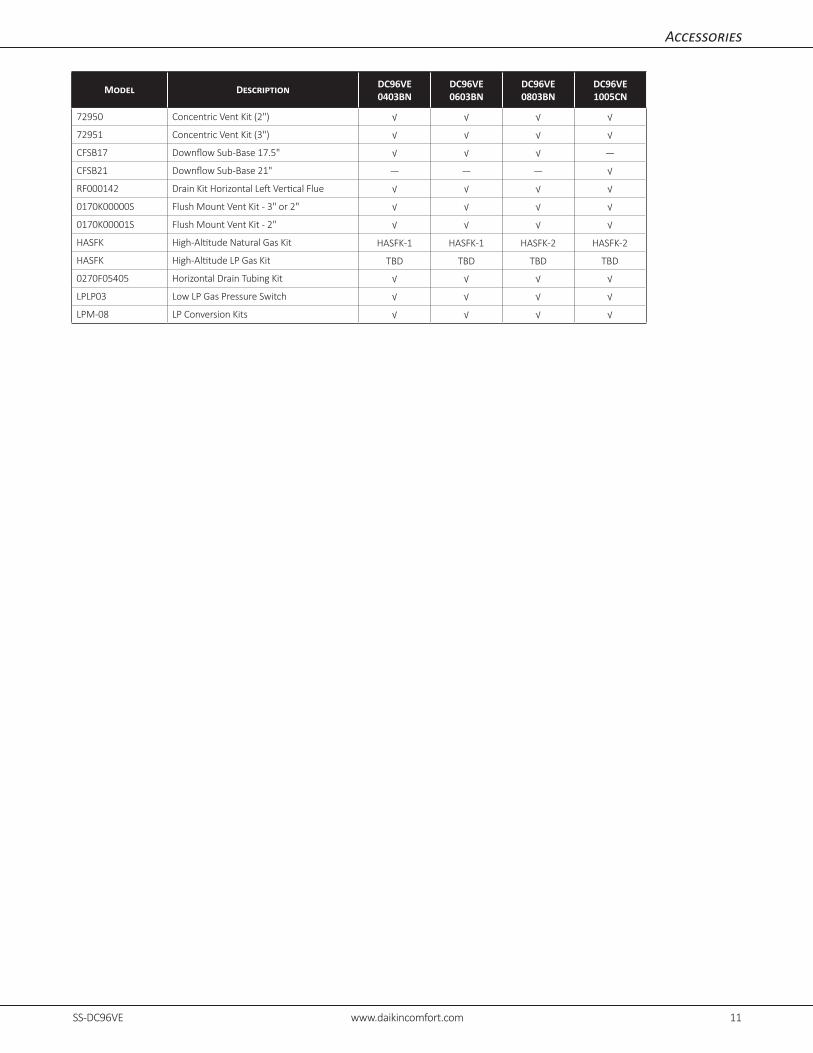
Accessories
Model Description DC96VE 0403BN
DC96VE 0603BN
DC96VE 0803BN
DC96VE 1005CN
72950 Concentric Vent Kit (2") √ √ √ √
72951 Concentric Vent Kit (3") √ √ √ √
CFSB17 Downflow Sub-Base 17.5" √ √ √ ―
CFSB21 Downflow Sub-Base 21" ― ― ― √
RF000142 Drain Kit Horizontal Left Vertical Flue √ √ √ √
0170K00000S Flush Mount Vent Kit - 3" or 2" √ √ √ √
0170K00001S Flush Mount Vent Kit - 2" √ √ √ √
HASFK High-Altitude Natural Gas Kit HASFK-1 HASFK-1 HASFK-2 HASFK-2
HASFK High-Altitude LP Gas Kit TBD TBD TBD TBD
0270F05405 Horizontal Drain Tubing Kit √ √ √ √
LPLP03 Low LP Gas Pressure Switch √ √ √ √
LPM-08 LP Conversion Kits √ √ √ √
12 www.daikincomfort.com SS-DC96VE SS-DC96VE www.daikincomfort.com PB
Our continuing commitment to quality products may mean a change in specifications without notice. © 2021 • Houston, Texas
Notes
Related Documents