Two Post Lift Manual DP15, DP15-2 Capacity 15,000 lbs. © September 2015 by Vehicle Service Group. All rights reserved. CO9345.3 994301 Rev. M 9/21/2015 OPERATING CONDITIONS Lift is not intended for outdoor use and has an operating ambient temperature range of 41°-104°F (5°-40°C) IMPORTANT Reference ANSI/ALI ALIS, Safety Requirements for Installation and Service of Automotive Lifts before installing lift.

Welcome message from author
This document is posted to help you gain knowledge. Please leave a comment to let me know what you think about it! Share it to your friends and learn new things together.
Transcript
Two Post Lift ManualDP15, DP15-2
Capacity 15,000 lbs.
© September 2015 by Vehicle Service Group. All rights reserved. CO9345.3994301
Rev. M 9/21/2015
OPERATING CONDITIONSLift is not intended for outdoor use
and has an operating ambient temperature range of
41°-104°F (5°-40°C)
IMPORTANT Reference ANSI/ALI ALIS, Safety Requirements for
Installation and Service of Automotive Lifts before installing lift.

2
Table of ContentsImportant Information .........................................................................................................................2
Section 1 Owner’s Manual
1. Safety Instructions ..........................................................................................................3
2. Monthly Maintenance ....................................................................................................6
3. Troubleshooting ...............................................................................................................6
4. Lift Lockout/Tagout Procedure .......................................................................................8
5. Operating Conditons .......................................................................................................9
6. Cylinder Replacement .....................................................................................................10
Section 2 Installation Instructions
1. Tools Required for Installation .......................................................................................11
2. Procedure ....... ..................................................................................................................11
Section 3 Parts Breakdown
1. Detailed Views & Parts List ............................................................................................29
Important Information1. Read this manual thoroughly before installing, operating, or maintaining this lift.
2. This lift is designed for indoor use only, and should not be installed in a pit or depression.
3. The floor on which the lift is to be installed must be 6” inch minimum thickness concrete, with a minimum compressive strength of 3000 psi, and reinforced with steel bar.
4. The lifts require 208-230V, 60 hz, single phase, 20 amp AC electrical service.
5. This lift has a minimum ceiling height requirement as described in the Installation Instructions section of this manual.
6. Failure by the owner to provide the recommended shelter, mounting surface, electrical supply, and ceil-ing height could result in unsatisfactory lift performance, property damage, or personal injury.
3
Owner’s Manual1. Safety Instructions:
1. Do not raise a vehicle on the lift until the installation is completed as described in this manual.
2. Anyone who will be in the vicinity of the lift when it is in use should read and refer to the following pub-lications supplied with this lift:
• “INSTALLATION AND OWNERS MANUAL”, I MAN 994301
• “LIFTING IT RIGHT”, ALI SM93-1.
• “AUTOMOTIVE LIFT SAFETY TIPS”, ALI-ST90.
• “VEHICLE LIFTING POINTS FOR FRAME ENGAGING LIFTS”, ALI/LP-GUIDE.
• “SAFETY REQUIREMENTS FOR OPERATION, INSPECTION, AND MAINTENANCE”, ANSI/ALI ALOIM-1994.
3. Technicians should be trained to use and care for the lift by familiarizing themselves with the publica-tions listed above. The lift should never be operated by an untrained person.
4. Always position the arms and adapters properly out of the way before pulling the vehicle into, or out of the bay. Failure to do so could damage the vehicle and/or the lift.
5. Do not overload the lift. The capacity of the lift is shown on cover of this document.
6. Positioning the vehicle is very important. Only trained technicians should position the vehicle on the lift. Never allow anyone to stand in the path of the vehicle as it is being positioned.
7. Position the arms to the vehicle manufacturer’s recommended pickup points. Raise the lift until contact is made with the vehicle. Make sure that the arms have properly engaged the vehicle before raising the lift to a working height.
8. Keep everyone clear of the lift when the lift is moving, the locking mechanism is disengaged, or the vehicle is in danger of falling.
9. Unauthorized personnel should never be in the shop area when the lift is in use.
10. Inspect the lift daily. The lift should never be operated if it has damaged components, or is malfunction-ing. Only qualified technicians should service the lift. Replace damaged components with manufac-turer’s parts, or equivalent.
11. Keep the area around the lift clear of obstacles.
12. Never override the self-returning lift controls.
13. Use safety stands when removing or installing heavy vehicle components.
14. Avoid excessive rocking of the vehicle when it is on the lift.
4
15. To reduce the risk of personal injury, keep hair, loose clothing, fingers, and all body parts away from moving parts.
16. To reduce the risk of electric shock, do not use the lift when wet, do not expose the lift to rain.
17. To reduce the risk of fire, do not operate equipment in the vicinity of open containers of flammable liquids (gasoline).
18. Use the lift only as described in this manual, use only manufacturer’s recommended attachments.
19. Unusual vehicles, such as limousines, RV’s, and long wheelbase vehicles, may not be suitable for lifting on this equipment. If necessary, consult with the manufacturer or the manufacturer’s representative.
20. The troubleshooting and maintenance procedures described in this manual can be done by the lift’s owner/employer. Any other procedure should only be performed by trained lift service personnel. These restricted procedures include, but are not limited to, the following: cylinder replacement, carriage and safety latch replacement, leg replacement, overhead structure replacement.
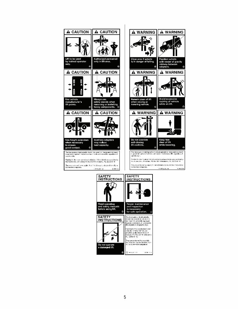
21. Anyone who will be in the vicinity of the lift when it is in use should familiarize themselves with following Caution, Warning, and Safety related decals supplied with this lift, and replace them if the are illegible or missing:
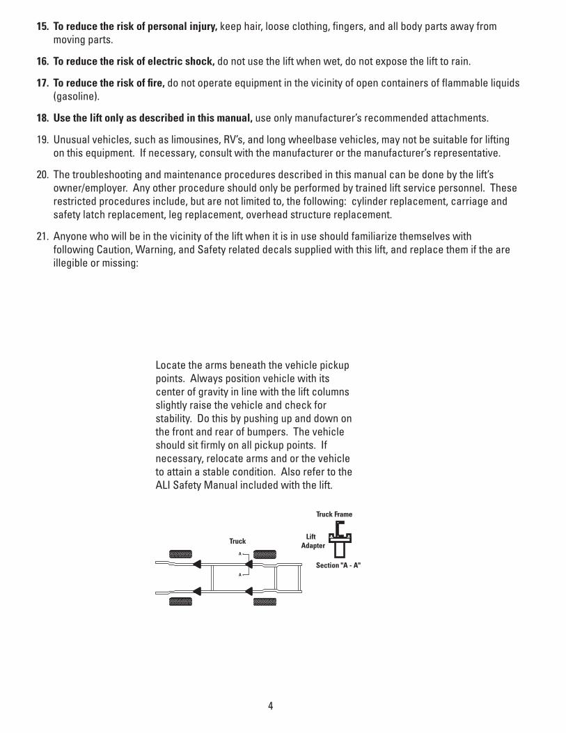
A
A
Truck
Section "A - A"
LiftAdapter
Truck Frame
Locate the arms beneath the vehicle pickup points. Always position vehicle with its center of gravity in line with the lift columns slightly raise the vehicle and check for stability. Do this by pushing up and down on the front and rear of bumpers. The vehicle should sit firmly on all pickup points. If necessary, relocate arms and or the vehicle to attain a stable condition. Also refer to the ALI Safety Manual included with the lift.
5

6
2. Monthly Maintenance:
1. Lubricate the four inside corners of the legs with heavy duty bearing grease.
2. With lift lowered check the hydraulic fluid level. If necessary add oil as described in the Installation Instruction section of this manual
3. Check carriage latch synching: Latches should click at the same time. If necessary adjust cables as described in the Installation Instruction section of this manual.
4. Check tightness of all bolts.
5. Check anchor bolt tightness. If the anchor bolts are loose, they should be re-torqued to 65ft/lbs.
• Check the nuts for tightness every week for the first month, and every month afterwards.
6. Replace worn or broken parts only with lift manufacturer’s parts, or their equivalent.
3. Troubleshooting:
1. The power unit does not run:
• Check electrical supply breaker, or fuse.
• Check for activation of the travel limit switch by a tall vehicle.
• Check micro-switch and connections in motor control box.
• Check voltage to the motor.
• Check micro-switch and connections in the overhead switch box.
2. The power unit runs but does not raise the lift:
• Check the oil level.
• Check that the lowering valve is not stuck open.
• Check the connections and components on the suction side of the pump.
3. The power unit raises the lift empty, but will not lift a vehicle.
• Make sure the vehicle is not above the rated capacity of the lift.
• Make sure the vehicle is positioned properly.
• Clean the lowering valve by running the power unit for 30 seconds while holding the lowering valve open.
• Check the motor voltage.
4. Lift drifts down.
• Check for external leaks.
• Clean the lowering valve by running the power unit for 30 seconds while holding the lowering valve open. Repeat this procedure three times.
• Clean the check valve seat.
5. Slow Lifting and/or oil foaming up.
• Check that oil used meets the specification in the Installation Instruction section of this manual.
• Tighten all suction line fittings.
7
6. Anchors continually work loose
• If holes were drilled too large relocate the lift per the Installation Instruction section of this manual.
• Floor is not sufficient to provide the necessary resistance, remove an area of concrete and re-pour as described in the Installation Instruction section of this manual.
7. Lift will not raise off of latches
• Motor, pump, or cylinder failure.
• Contact lift manufacturer’s Customer Service.
8. Lift does not raise and lower smoothly.
• Reposition vehicle for a more even weight distribution.
• Check the four inside corners of the two legs for roughness. Any rust or burrs must be removed with 120 grit emery cloth.
• Lubricate the leg corners with heavy duty bearing grease.
• Use a level to check the legs for vertical alignment both side to side and front to back. Shim the legs as necessary per the Installation Instruction section of this manual.
• Check the oil level.
• Make sure there is no air in the hydraulic lines, bleed system as described in the Installation Instruction section of this manual.
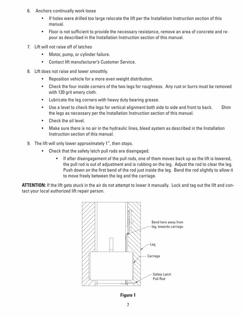
9. The lift will only lower approximately 1”, then stops.
• Check that the safety latch pull rods are disengaged.
• If after disengagement of the pull rods, one of them moves back up as the lift is lowered, the pull rod is out of adjustment and is rubbing on the leg. Adjust the rod to clear the leg. Push down on the first bend of the rod just inside the leg. Bend the rod slightly to allow it to move freely between the leg and the carriage.
ATTENTION: If the lift gets stuck in the air do not attempt to lower it manually. Lock and tag out the lift and con-tact your local authorized lift repair person.
Bend here away fromleg, towards carriage.
Leg
Carriage
Safety LatchPull-Rod
Figure 1
8
10. At full rise the latch will not disengage and the lift cannot be lowered.
• If the equalization cables are out of adjustment the carriages are out of sync, and when the lift is at full rise one of the safety latches may not have the clearance to disengage and allow the lift to lower.
• To lower the lift
→ Raise the lift to full height.
→ Push In both safety latch pull rods to engage latches.
→ Use a hydraulic jack and a length of pipe to raise the carriage with the lock which is
sticking enough to disengage the safety latch. Pull the latch rod on that carriage only.
→ Remove the jack and pipe.
→ Pull the latch rod on the other carriage to disengage the latch.
→ Lower the lift and remove the vehicle.
→ Readjust the cables as described in the Installation Instruction section of this manual.
11. Power Unit will not stop running
• Switch is damaged, turn off power to the lift and replace switch.
4. Lift Lockout/Tagout Procedure:
Purpose
This procedure establishes the minimum requirements for the lockout of energy that could cause injury to per-sonnel by the operation of lifts in need of repair or being serviced. All employees shall comply with this proce-dure.
Responsibility
The responsibility for assuring that this procedure is followed is binding upon all employees and service person-nel from outside service companies (i.e., authorized installers, contactors, etc.). All employees shall be instruct-ed in the safety significance of the lockout procedure by the facility owner/manager. Each new or transferred employee along with visiting outside service personnel shall be instructed by the owner/manager (or assigned designee) in the purpose and use of the lockout procedure.
Preparation
Employees authorized to perform lockout shall ensure that the appropriate energy isolating device (i.e., circuit breaker, fuse, disconnect, etc.) is identified for the lift being locked out. Other such devices for other equipment may be located in close proximity of the appropriate energy isolating device. If the identity of the device is in question, see the shop supervisor for resolution. Assure that proper authorization is received prior to performing the lockout procedure.

9
Sequence of Lockout Procedure
1. Notify all affected employees that a lockout is being performed and the reason for it.
2. Unload the subject lift. Shut it down and assure the disconnect switch is “OFF” if one is provided on the lift.
3. The authorized lockout person operates the main energy isolation device removing power to the subject lift.
• If this is a lockable device, the authorized lockout person places the assigned padlock on the device to prevent its unintentional reactivation. An appropriate tag is applied stating the per-son’s name, at least 3” x 6” in size, an easily noticeably color, and states not to operate device or remove tag.
• If this device is a non-lockable circuit breaker or fuse, replace with a “dummy” device and tag it appropriately as mentioned above.
4. Attempt to operate lift to assure the lockout is working. Be sure to return any switches to the “OFF” posi-tion.
Restoring Equipment to Service
1. Assure the work on the lift is complete and the area is clear of tools, vehicles, and personnel.
2. At this point, the authorized person can remove the lock (or dummy circuit breaker or fuse) & tag and activate the energy isolating device so that the lift may again be placed into operation.
Rules for Using Lockout Procedure
Use the Lockout Procedure whenever the lift is being repaired or serviced, waiting for repair when current operation could cause possible injury to personnel, or for any other situation when unintentional operation could injure personnel. No attempt shall be made to operate the lift when the energy isolating device is locked out.
5. Operating Conditions:
Lift is not intended for outdoor use and has an operating ambient temperature range of 41º-104ºF (5º-40ºC).
*Maximum operation pressure is:2103 psi for DP15, DP15-2
10
5. Cylinder Replacement:
1. This task is to be performed by trained lift service personnel only.
2. Raise the lift carriages a few inches.
3. Place a 2” spacer under each carriage.
4. Lower carriages onto the spacers.
5. Do not hold the cylinder rod with anything that will damage the finish. Cylinder leaks caused by dam-aged rods are not covered by warranty. Hold the 1” full nut and remove the jam nut.
6. Remove the full nut.
7. Remove the pressure hose from the bottom fitting of the cylinder. Mark the inlet position on carriage.
8. Remove the return hose from the top of the cylinder.
9. Pull the rod from the carriage bottom plate.
10. Push the rod into the cylinder to prevent damage to the rod during handling.
11. Remove the cylinder from the upright by taking out the 3/4” x 5 grade 8 bolt at the top of the cylinder.
12. Reverse the procedure to replace the cylinder, being careful to position the pressure hose inlet to achieve proper orientation.
13. Bleed hydraulic system as described in the Installation Instruction section of this manual.
11
Installation Instructions1. Tools Required for Installation:
• Concrete hammer drill with 3/4” bit
• 11/16” open end wrench
• 3/4” open end wrench
• Torque wrench
• 15/16” deep socket or wrench
• 1-1/8” socket
• 13/16” open end wrench
• Level (18” minimum length)
• Vise grips
• Tape measure
• Funnel
• Hoist or Forklift (optional)
• Two 12’ step ladders
• 1/4” drive ratchet with 5/16” socket
2. Procedure:
1. Read this manual thoroughly before installing, operating, or maintaining this lift.
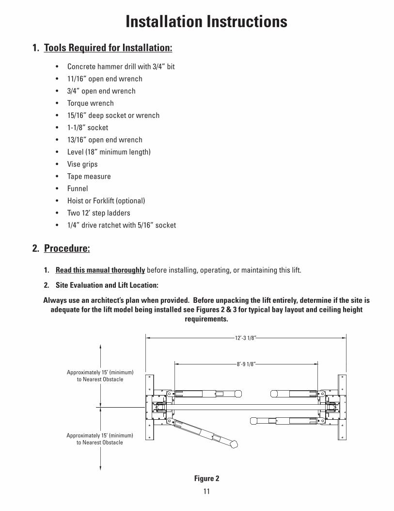
2. Site Evaluation and Lift Location:
Always use an architect’s plan when provided. Before unpacking the lift entirely, determine if the site is adequate for the lift model being installed see Figures 2 & 3 for typical bay layout and ceiling height
requirements.
Figure 2
12’-3 1/8”
Approximately 15’ (minimum)to Nearest Obstacle
Approximately 15’ (minimum)to Nearest Obstacle
8’-9 1/8”

12
Figure 3
Carriage Cable Overhead WeldmentHydraulic Hoses
Safety Shut-Off Bar
Offside Leg
16’-8”Min. Recommended
Ceiling Height forExtended Lift
16’-7”Optional Extended
Lift Height
14’-8”Min. Recommended
Ceiling Height
14’-7”Lift Height
Power Unit
CarriageSwing Arms
Mainside Leg
A. Note the mainside leg has a mounting bracket on its back for the power unit. The mainside leg is typically located on the passenger side of the lift.
B. Layout and mark the floor for the leg placement locations.
3. Unpack the lift. Remove the swing arms, bolt box, power unit box, and overhead beam. Save all packing hardware, as these components are necessary to complete the installation.
A. Remove the ½” bolts from the packing bracket which holds the two legs together.
B. Remove the top leg. Do not stand legs up, instead lay the legs flat on their backs on the floor.
13
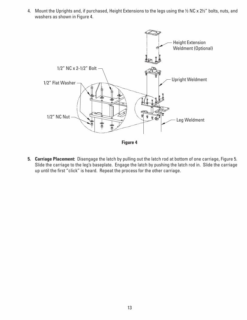
4. Mount the Uprights and, if purchased, Height Extensions to the legs using the ½ NC x 2½” bolts, nuts, and washers as shown in Figure 4.
Height ExtensionWeldment (Optional)
Upright Weldment
Leg Weldment1/2” NC Nut
1/2” Flat Washer
1/2” NC x 2-1/2” Bolt
Figure 4
5. Carriage Placement: Disengage the latch by pulling out the latch rod at bottom of one carriage, Figure 5. Slide the carriage to the leg’s baseplate. Engage the latch by pushing the latch rod in. Slide the carriage up until the first “click” is heard. Repeat the process for the other carriage.

14
Figure 5
Latch Rod
Engaged DisengagedPull Out
Safety Lock
6. Install Hydraulic Cylinders, Fittings, and Hoses
A. Warning: When attaching hydraulic fittings with pipe threads to the cylinders use Teflon tape. DO NOT start the Teflon tape closer than 1/8” from the end of the fitting. Failure to comply may cause damage to the hydraulic system.
B. Warning: When making tightening connections with flared (JIC) fittings, always follow the tightening instructions. Failure to follow these instructions may result in cracked fittings and / or leaks.
• Use the proper size wrench,
• The nut portion of the fitting is the only part that should turn during tightening. The flare seat MUST NOT turn.
• Screw the fittings together hand tight.
• Use the proper size wrench to rotate the nut portion of the fitting 2-1/2 hex flats.
• Back the fitting off one full turn.
• Again, tighten the fitting hand tight, then rotate the nut portion of the fitting 2-1/2 hex flats.
C. Remove the plugs from each port on the cylinders.
D. Connect a male pipe thread to male JIC elbow to the port near the rod end of each cylinder. The fit-tings should face away from the leg’s baseplate.
E. Connect the shortest hydraulic hose to the elbow on the cylinder to be used in the mainside leg. This connection should be hand-tight only. The mainside leg is identifiable by the power unit bracket and hose guides welded to it.
15
F. Connect the longest hose to the elbow attached to the cylinder to be used in the offside leg, again hand tight.
G. Connect a male pipe thread to female pipe thread bushing to the port on the cap end of each cylinder.
H. Connect the ¼” airline tee to the bushing on the mainside leg cylinder. The side connection of the tee should face one of the openings in the upright.
I. Connect the other ¼” airline fitting to the bushing on the capped end of the cylinder.
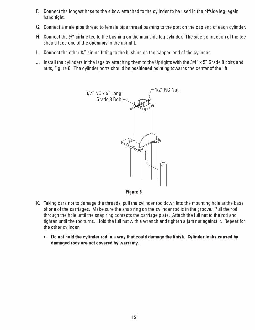
J. Install the cylinders in the legs by attaching them to the Uprights with the 3/4” x 5” Grade 8 bolts and nuts, Figure 6. The cylinder ports should be positioned pointing towards the center of the lift.
1/2” NC x 5” LongGrade 8 Bolt
1/2” NC Nut
K. Taking care not to damage the threads, pull the cylinder rod down into the mounting hole at the base of one of the carriages. Make sure the snap ring on the cylinder rod is in the groove. Pull the rod through the hole until the snap ring contacts the carriage plate. Attach the full nut to the rod and tighten until the rod turns. Hold the full nut with a wrench and tighten a jam nut against it. Repeat for the other cylinder.
• Do not hold the cylinder rod in a way that could damage the finish. Cylinder leaks caused by damaged rods are not covered by warranty.
Figure 6

16
7. Leg Positioning and Anchoring
A. Raise the Mainside leg only and position it where it is to be secured.
B. The anchor bolts must be installed at least 5-11/16” from any edge or seam in the concrete
C. The concrete must be at least 6” thick with a compression strength of 3,000 psi.
D. Using the leg as a template, drill the eight anchor bolt holes for the Mainside Leg Only!!
• Use a hammer drill with a Carbide tip, 3/4” diameter, solid drill bit. The bit tip diameter should be to ANSI Standard B95.12-1977. (.775” to .787”).
• Keep the drill perpendicular to the floor while drilling.
• Let the drill do the work. Do not apply excessive pressure.
• Lift the drill up and down to remove dust and reduce binding.
• Drill the hole completely through the slab.
• Clean the dust from the hole.
E. Seismic Installations: Varies by location consult with your structural engineer and manufacturer’s reprsentative.
F. Assemble the washers and nuts onto the anchor bolts. Thread the nuts onto the anchor bolts where the tops of the nuts are just above the top of the bolts, Figure 7. Using a hammer, carefully tap the anchor bolts into the concrete until the washer rests against the baseplate. Do not damage the nuts or threads.
G. Using a level, plumb the mainside leg both side to side and front to back. Shim the leg as necessary next to and on both sides of the anchor bolts. If more than 1/2” of shimming is required, do not use the anchors and small shims provided with the lift.
• Use longer anchors and fabricate larger shims from steel flat, 1/4” or 1/2” thick by 2”, or more, wide.
Figure 7
17
Figure 8
H. Once the leg is plumb tighten the anchor bolts to 110 ft-lbs. Do not use an impact wrench on anchor bolts.
• If after tightening the anchor supplied with the lift extends more than 2-1/4” above the floor the anchor does not have enough embedment.
• If an anchor will not reach 110 ft-lbs or does not have enough embedment or adequate spacing cannot be achieved, replace the concrete under the leg with a 5’ X 5’ X 6” thick pad of 3,000 psi concrete keyed under the existing floor. Let the concrete cure before reinstalling the lift.
I. Recheck the leg’s plumbness after tightening the anchor bolts. Add shims if necessary.
J. Raise the offside leg and position it where it is to be located. Do not drill holes for anchors.
SEISMIC - Varies by location consultwith your structural engineer and
manufacturer’s representative.
*The supplied concrete fasteners meet the criteria of the American National Standard “Automotive Lifts - Safety Requirements for Construction, Testing, and Validation” ANSI/ALI ALCTV-2011, and the lift owner is responsible for all charges related to any additional anchoring requirements as specified by local codes.
Contact customer service for further information at: 800.640.5438
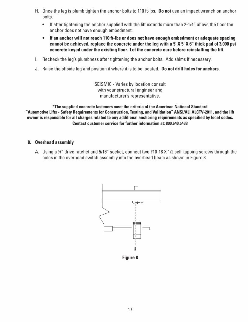
8. Overhead assembly
A. Using a ¼” drive ratchet and 5/16” socket, connect two #10-18 X 1/2 self-tapping screws through the holes in the overhead switch assembly into the overhead beam as shown in Figure 8.
18
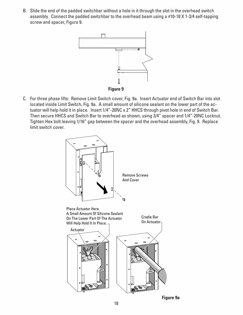
B. Slide the end of the padded switchbar without a hole in it through the slot in the overhead switch assembly. Connect the padded switchbar to the overhead beam using a #10-18 X 1-3/4 self-tapping screw and spacer, Figure 9.
C. For three phase lifts: Remove Limit Switch cover, Fig. 9a. Insert Actuator end of Switch Bar into slot located inside Limit Switch, Fig. 9a. A small amount of silicone sealant on the lower part of the ac-tuator will help hold it in place. Insert 1/4”-20NC x 2” HHCS through pivot hole in end of Switch Bar. Then secure HHCS and Switch Bar to overhead as shown, using 3/4” spacer and 1/4”-20NC Locknut. Tighten Hex bolt leaving 1/16” gap between the spacer and the overhead assembly, Fig. 9. Replace limit switch cover.
Figure 9
Place Actuator Here.A Small Amount Of Silicone SealantOn The Lower Part Of The ActuatorWill Help Hold It In Place.
Cradle Bar On Actuator
Actuator
Remove ScrewsAnd Cover
Figure 9a

19
D. Attach the overhead beam to the uprights.
• Raise the overhead beam and secure it to the top of the uprights using eight 1/2 x 2-1/2 bolts, Figure 10.
• For extended height models raise the overhead beam and secure it to the top of the Height Exten-sions using four 1/2 x 2-1/2” bolts at each end.
9. Anchoring offside leg
A. Using a level check the alignment and plumbness of the entire structure. Plumb the offside leg both side to side and front to back.
B. The base of the leg may vary slightly from the preliminary layout, as it is more important that the leg be perpendicular to the floor and parallel to the other leg.
C. Install the anchor bolts and shim the base as described in the earlier “Leg positioning and anchoring” step.
1/2” NC x 2-1/2” Bolt
1/2” NC Nut
1/2” Flat Washer
Figure 10

20
10. Assemble carriage cables
A. The carriages should be resting on the same safety rack tooth. Measure the height above the base-plate for each carriage. The measurements should be within 3/8” of each other. Make a note of the two measurements.
B. Standing between the two legs looking at either carriage, push one end of a cable down through the right-rear hole in the top of the carriage until the cable hits the floor.
C. Attach a 3/4” nylon insert nut with an SAE washer to the end of the cable. Connect the nut to the cable so that approximately 1/8” of the cable end sticks past the end of the nut.
D. Running the cables, Figure 11.
• Thread the other end of the cable up through the upright,
• Over the rightmost pulley at the top of the lift,
• Over to the leftmost overhead pulley on the other side of the lift,
• Down through the left rear hole in the top of the carriage,
• Around the pulley in the bottom of the leg,
• Up through the left-front hole in the top of the carriage.
E. Secure the cable end with a 3/4 nylon insert nut and SAE washer. Do not tighten the cable at this time.
F. Repeat the process for the other cable, taking care not to cross them.
G. Take out the slack, but do not tighten, both cables by turning down the nuts on the top of each car-riage top. Use vise grips to hold the cable end, but be very careful not to damage the threads.
H. The carriages must remain at the same lock position while the cables are being tightened. Overtight-ening of one cable could raise the carriage in the opposite leg and cause the carriage safety latches to be out of sync.
I. Alternately tighten the cable nuts at both carriages until the cables are tightened. Correct tension in the cables is indicated by approximately 1/4” deflection on the cable in the leg when pulled at its midpoint.
J. Measure and compare the carriage heights to the earlier measurement, or check that the safety latch pull rod will not disengage to verify that neither carriage has been raised. If a carriage has been raised more than 1/8”, loosen the cables and repeat the procedure.
21
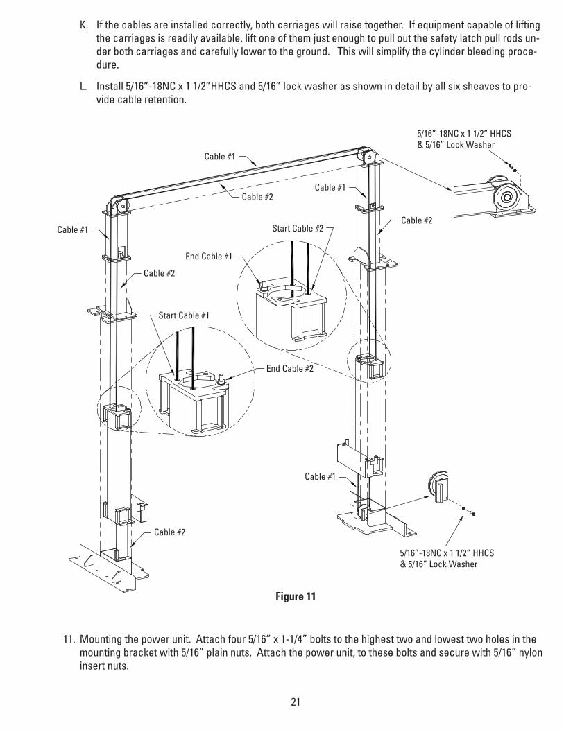
K. If the cables are installed correctly, both carriages will raise together. If equipment capable of lifting the carriages is readily available, lift one of them just enough to pull out the safety latch pull rods un-der both carriages and carefully lower to the ground. This will simplify the cylinder bleeding proce-dure.
L. Install 5/16”-18NC x 1 1/2”HHCS and 5/16” lock washer as shown in detail by all six sheaves to pro-vide cable retention.
11. Mounting the power unit. Attach four 5/16” x 1-1/4” bolts to the highest two and lowest two holes in the mounting bracket with 5/16” plain nuts. Attach the power unit, to these bolts and secure with 5/16” nylon insert nuts.
Figure 11
Cable #1
Cable #2
Start Cable #1
Start Cable #2
End Cable #2
End Cable #1
Cable #2
Cable #2
Cable #1
Cable #1
Cable #1
Cable #2
5/16”-18NC x 1 1/2” HHCS & 5/16” Lock Washer
5/16”-18NC x 1 1/2” HHCS & 5/16” Lock Washer
22
Figure 12
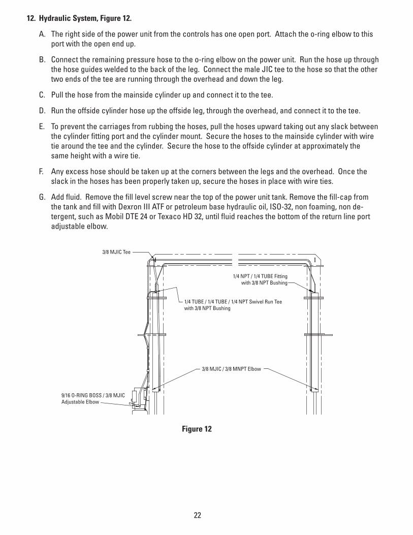
12. Hydraulic System, Figure 12.
A. The right side of the power unit from the controls has one open port. Attach the o-ring elbow to this port with the open end up.
B. Connect the remaining pressure hose to the o-ring elbow on the power unit. Run the hose up through the hose guides welded to the back of the leg. Connect the male JIC tee to the hose so that the other two ends of the tee are running through the overhead and down the leg.
C. Pull the hose from the mainside cylinder up and connect it to the tee.
D. Run the offside cylinder hose up the offside leg, through the overhead, and connect it to the tee.
E. To prevent the carriages from rubbing the hoses, pull the hoses upward taking out any slack between the cylinder fitting port and the cylinder mount. Secure the hoses to the mainside cylinder with wire tie around the tee and the cylinder. Secure the hose to the offside cylinder at approximately the same height with a wire tie.
F. Any excess hose should be taken up at the corners between the legs and the overhead. Once the slack in the hoses has been properly taken up, secure the hoses in place with wire ties.
G. Add fluid. Remove the fill level screw near the top of the power unit tank. Remove the fill-cap from the tank and fill with Dexron III ATF or petroleum base hydraulic oil, ISO-32, non foaming, non de-tergent, such as Mobil DTE 24 or Texaco HD 32, until fluid reaches the bottom of the return line port adjustable elbow.
3/8 MJIC Tee
9/16 O-RING BOSS / 3/8 MJICAdjustable Elbow
3/8 MJIC / 3/8 MNPT Elbow
1/4 TUBE / 1/4 TUBE / 1/4 NPT Swivel Run Teewith 3/8 NPT Bushing
1/4 NPT / 1/4 TUBE Fittingwith 3/8 NPT Bushing
23
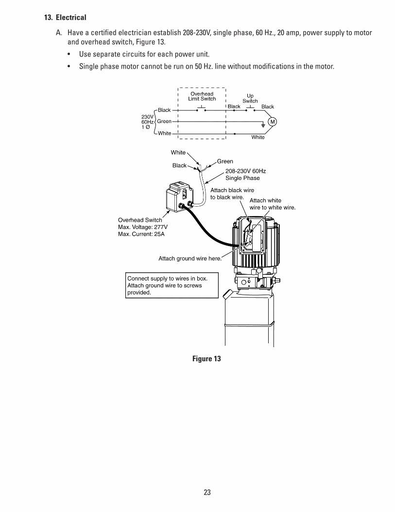
13. Electrical
A. Have a certified electrician establish 208-230V, single phase, 60 Hz., 20 amp, power supply to motor and overhead switch, Figure 13.
• Use separate circuits for each power unit.
• Single phase motor cannot be run on 50 Hz. line without modifications in the motor.
Figure 13
24
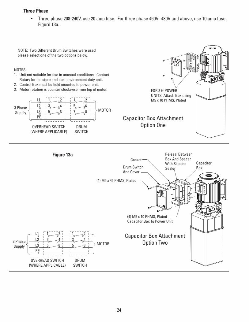
Figure 13a
Capacitor Box AttachmentOption Two
L1
PE
L2L3
135
246 MOTOR
135
246
OVERHEAD SWITCH(WHERE APPLICABLE)
DRUMSWITCH
3 PhaseSupply
Capacitor Box AttachmentOption One
L1
PE
L2L3
135
246 MOTOR
157
268
OVERHEAD SWITCH(WHERE APPLICABLE)
DRUMSWITCH
3 PhaseSupply
FOR 3 Ø POWERUNITS: Attach Box using M5 x 10 PHMS, Plated
NOTES:1. Unit not suitable for use in unusual conditions. Contact
Rotary for moisture and dust environment duty unit.2. Control Box must be field mounted to power unit. 3. Motor rotation is counter clockwise from top of motor.
NOTE: Two Different Drum Switches were usedplease select one of the two options below.
(4) M5 x 45 PHMS, Plated
(4) M5 x 10 PHMS, Plated Capacitor Box To Power Unit
Drum Switch And Cover
Re-seal BetweenBox And SpacerWith SiliconeSealer
CapacitorBox
Gasket
Three Phase
• Three phase 208-240V, use 20 amp fuse. For three phase 460V -480V and above, use 10 amp fuse, Figure 13a.
25
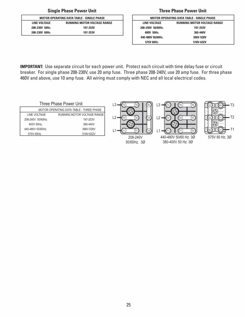
Single Phase Power UnitMOTOR OPERATING DATA TABLE - SINGLE PHASE
LINE VOLTAGE RUNNING MOTOR VOLTAGE RANGE 208-230V 50Hz. 197-253V 208-230V 60Hz. 197-253V
Three Phase Power UnitMOTOR OPERATING DATA TABLE - SINGLE PHASE
LINE VOLTAGE RUNNING MOTOR VOLTAGE RANGE 208-240V 50/60Hz. 197-253V 400V 50Hz. 360-440V 440-480V 50/60Hz. 396V-528V 575V 60Hz. 518V-632V
IMPORTANT: Use separate circuit for each power unit. Protect each circuit with time delay fuse or circuit breaker. For single phase 208-230V, use 20 amp fuse. Three phase 208-240V, use 20 amp fuse. For three phase 460V and above, use 10 amp fuse. All wiring must comply with NEC and all local electrical codes.
T7T1
T8T2
T9T3
T4
T5
T6
L1
L2
L3
T7 T4T1L1
T8 T5T2L2
T9 T6T3L3
T1
T2
T3
U2
V2
W2
W1
V1
U1
208-240V50/60Hz. 3Ø
440-480V 50/60 Hz. 3Ø380-400V 50 Hz. 3Ø
575V 60 Hz. 3Ø
Three Phase Power UnitMOTOR OPERATING DATA TABLE - THREE PHASE
LINE VOLTAGE RUNNING MOTOR VOLTAGE RANGE 208-240V 50/60Hz. 197-253V 400V 50Hz. 360-440V 440-480V 50/60Hz. 396V-528V 575V 60Hz. 518V-632V

26
14. Bleeding the hydraulic system, Figure 12.
A. Loosen the connections between the hoses and fittings attached to the cylinders. Do not loosen the connections between the fittings and the cylinders themselves.
B. Run the power unit until fluid appears at the mainside cylinder port. Tighten that hose connection.
C. Run the power unit until fluid appears at the offside cylinder port and there is no more air. Tighten that hose connection.
D. Lower the lift to the ground. If the lift is on the safety latches, raise the lift enough to disengage the latches and then lower.
E. If the carriages were on the ground when the bleeding process was begun, no further bleeding is required. If not, repeat the previous steps for bleeding the hydraulic system.
F. Add fluid to the system as previously described.
15. Connecting the return lines, Figure 12.
A. Take special care not to kink the plastic return lines.
B. From the power unit run one end of the ¼” plastic tubing up through the hose guides and connect it to the tee attached to the top of the mainside cylinder.
C. Measure out enough tubing to adequately reach the fitting on the back of the power unit tank. Cut the tubing and connect it to the fitting.
D. Connect one end of the remaining tubing to the open port in the tee at the top of the mainside cylin-der.
E. Run the free end of the tubing up the mainside column, through the overhead and down the offside column. Cut off excess tubing and connect the hose to the fitting on the top of the offside cylinder.

27
16. Assembling the Arms and Arm Restraints:
• Install the swing arms with the swing arm pins, Figure 14.
• Install spring pin to secure arm pins, Figure 14.
• Install the swing arm restraints, Figure 15.
Arm Pin
Spring Pin
Arm
Figure 14
Figure 15
(12) 3/8"-16NC x 1-1/2" Lg. HHCS(12) 3/8" Spring Lockwashers
Arm
Restraint Gear B
Arm Clevis
TOP will be marked on top
side of restraint gear NOTE beveled
gear orientation
17. Lubricate the four inside corners of both legs with heavy duty bearing grease.

28
17. Final Adjustments
A. If any problems are encountered, do not proceed with subsequent steps. Instead, resolve the prob-lem before proceeding by referencing the Troubleshooting portion of the Owner’s Manual section of this manual.
B. Raise the lift to full height. Lower the lift onto the safety latches. Raise the carriages, pull out both latch pull rods, and lower the lift to the ground.
C. Raise the lift empty to the top of its travel and lower it the floor three (3) times to remove the remain-ing air from the hydraulic system.
D. The latches should click together as the lift is being raised.
E. When the carriages are lowered onto the locks, neither pull rod should be capable of being pulled out.
F. The first time a vehicle is placed on the lift, raise it no higher than three feet. Lower the vehicle onto the safety latches. Raise the lift a few inches and pull out both latch pull rods then lower the vehicle to the floor.
G. Raise the vehicle to full height and lower the carriages onto the safety latches. Lower the vehicle to the floor.
H. After cycling the lift ten times with a vehicle on it, recheck the tightness of the anchors to at least 110 ft-lbs.

29
Parks Breakdown
9
9
8 7 6
13 14 31 34 35
13
19
15
16
21
26
1920214547
42
234446
15
1112
28
1718
2625
10
1
10
43
1817
3032
42
2728
20
14313335
49
41
70
4039
36
67
68
HEIGHT EXTENSIONOPTIONAL
37
2
2
3
5 29
4
6922
Figure 16

30
Figure 17
50
53 55
51
52
54
57
60
61
63
6462
65 66
52
56
59
54
55
51
48
53
58
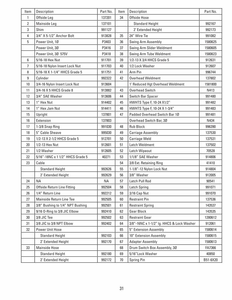
31
Item Description Part No. Item Description Part No.
1 Offside Leg 137201 34 Offside Hose
2 Mainside Leg 137101 Standard Height 992167
3 Shim 991127 2’ Extended Height 992173
4 3/4” X 5-1/2” Anchor Bolt 913828 35 24” Wire Tie 991082
5 Power Unit, 1Ø P3403 36 Swing Arm Assembly 1580625
Power Unit, 3Ø P3416 37 Swing Arm Slider Weldment 1580605
Power Unit, 3Ø 575V P3418 38 Swing Arm Tube Weldment 1580623
6 5/16-18 Hex Nut 911701 39 1/2-13 X 3/4 HHCS Grade 5 912631
7 5/16-18 Nylon Insert Lock Nut 911703 40 1/2 Lock Washer 912607
8 5/16-18 X 1-1/4” HHCS Grade 5 911751 41 Arm Pin 996744
9 Cylinder 992322 42 Overhead Weldment 137802
10 3/4-16 Nylon Insert Lock Nut 913604 1’ Reduced Hgt Overhead Weldment 1581800
11 3/4-16 X 5 HHCS Grade 8 913882 43 Overhead Switch N413
12 3/4” SAE Washer 913606 44 Switch Bar Spacer 991480
13 1” Hex Nut 914402 45 HWHTS Type F, 10-24 X1/2” 991482
14 1” Hex Jam Nut 914411 46 HWHTS Type F, 10-24 X 1-3/4” 991483
15 Upright 137801 47 Padded Overhead Switch Bar 1Ø 991481
16 Extension 137803 Overhead Switch Bar, 3Ø N434
17 1-3/8 Snap Ring 991030 48 Rub Block 996390
18 5” Cable Sheave 995030 49 Carriage Assembly 137530
19 1/2-13 X 2-1/2 HHCS Grade 5 912701 50 Carriage Weld 137531
20 1/2-13 Hex Nut 912601 51 Latch Weldment 137502
21 1/2 Washer 912605 52 Latch Wipeout 70528
22 5/16”-18NC x 1 1/2” HHCS Grade 5 40271 53 1/1/8” SAE Washer 914806
23 Cable 54 3/8 Ext. Retaining Ring 41410
Standard Height 992626 55 1-1/8”-12 Nylon Lock Nut 914804
2’ Extended Height 992629 56 3/8” Washer 912005
24 NA NA 57 Latch Pull Rod 90541
25 Offside Return Line Fitting 992504 58 Latch Spring 991071
26 1/4” Return Line 992212 59 3/16 Cap Nut 991070
27 Mainside Return Line Tee 992505 60 Restraint Pin 137536
28 3/8” Bushing to 1/4” NPT Bushing 992501 61 Restraint Spring 143537
29 9/16 O-Ring to 3/8 JIC Elbow 992410 62 Gear Block 143535
30 3/8 JIC Tee 992502 63 Restraint Gear 1280612
31 3/8 JIC to 3/8 NPT Elbow 992402 64 3/8”-16NC x 1-1/2” lg. HHCS & Lock Washer 912061
32 Power Unit Hose 65 5” Extension Assembly 1580614
Standard Height 992103 66 10” Extension Assembly 1580615
2’ Extended Height 992170 67 Adapter Assembly 1580613
33 Mainside Hose 68 Drum Switch Box Assembly, 3Ø FA7366
Standard Height 992180 69 5/16”Lock Washer 40850
2’ Extended Height 992172 70 Spring Pin B51-6X20

Related Documents