This article appeared in a journal published by Elsevier. The attached copy is furnished to the author for internal non-commercial research and education use, including for instruction at the authors institution and sharing with colleagues. Other uses, including reproduction and distribution, or selling or licensing copies, or posting to personal, institutional or third party websites are prohibited. In most cases authors are permitted to post their version of the article (e.g. in Word or Tex form) to their personal website or institutional repository. Authors requiring further information regarding Elsevier’s archiving and manuscript policies are encouraged to visit: http://www.elsevier.com/copyright

Welcome message from author
This document is posted to help you gain knowledge. Please leave a comment to let me know what you think about it! Share it to your friends and learn new things together.
Transcript
This article appeared in a journal published by Elsevier. The attachedcopy is furnished to the author for internal non-commercial researchand education use, including for instruction at the authors institution
and sharing with colleagues.
Other uses, including reproduction and distribution, or selling orlicensing copies, or posting to personal, institutional or third party
websites are prohibited.
In most cases authors are permitted to post their version of thearticle (e.g. in Word or Tex form) to their personal website orinstitutional repository. Authors requiring further information
regarding Elsevier’s archiving and manuscript policies areencouraged to visit:
http://www.elsevier.com/copyright

Author's personal copy
Sensors and Actuators B 151 (2011) 384–393
Contents lists available at ScienceDirect
Sensors and Actuators B: Chemical
journa l homepage: www.e lsev ier .com/ locate /snb
Two-layer multiplexed peristaltic pumps for high-density integratedmicrofluidics
Matthew C. Cole, Amit V. Desai, Paul J.A. Kenis ∗
University of Illinois at Urbana-Champaign, Department of Chemical & Biomolecular Engineering, 600 S. Mathews Ave., Urbana, IL 61801, USA
a r t i c l e i n f o
Article history:Received 27 January 2010Received in revised form 18 May 2010Accepted 8 July 2010Available online 15 July 2010
Keywords:Microfluidic multiplexingPneumatic valves and pumpsMultilayer soft lithography
a b s t r a c t
The integration and operation of a large number of components is needed to enable ever more complexand integrated chemical and biological processes on a single microfluidic chip. The capabilities of thesechips are often limited by the maximum number of pumps and valves that can be controlled on a singlechip, a limitation typically set by the number of pneumatic interconnects available from ancillary hard-ware. Here, we report a multiplexing approach that greatly reduces the number of external pneumaticconnections needed for the operation of a large number of peristaltic pumps. The utility of the approachis demonstrated with a complex microfluidic network capable of generating and routing liquid dropletsin a two-phase flow. We also report a set of design rules for the design and operation of multiplexedperistaltic pumps, based on a study of the effect of the number of valves per pump and the valve-to-valve distance on the performance of peristaltic pumps. The multiplexing approach reported here mayfind application in a wide range of microfluidic chips for chemical and biological applications, especiallythose that require the integration of many different operations on a single chip and those that need toperform similar operations massively in parallel, in sub-nanoliter volumes.
© 2010 Elsevier B.V. All rights reserved.
1. Introduction
The advent of VLSI (Very Large Scale Integration) microfluidicshas enabled multi-step and high-throughput applications withmassively parallel operations to be performed on a single chip[1–4]. Key to the development of VLSI microfluidics was the capa-bility to integrate a large number of microfluidic components, suchas valves, pumps, chemical reactors and analytical chambers, on asingle chip with high density. Of all these microfluidic components,valves and pumps have received the most attention, because theseactive components are responsible for routing the fluids in almostany complex network of microchannels.
Different approaches to integrate the valves and pumps inmicrofluidic networks, which primarily differ in the actuationprinciple of these active components, have been reported in the lit-erature. For example, researchers have integrated pumps based onelectrochemical [5], electrostatic [6], and pneumatic [7] actuationand valves based on magnetic [8], piezoelectric [9] and pneu-matic [10] actuation. Several of these technologies for integrationhave been summarized in a recent review [11]. However, most ofthese technologies are not amenable to integration into complexhigh-density microfluidic chips, due to the intensive nature of the
∗ Corresponding author. Tel.: +1 217 265 0523.E-mail addresses: [email protected], [email protected] (P.J.A. Kenis).
required fabrication procedures, actuation crosstalk between adja-cent components, and /or incompatibility of the actuation principlewith the chemical or biological process the chip is supporting. Akey exception is the pneumatically actuated valves and pumps,which possess a small footprint, fast response time, can be eas-ily integrated, and do not suffer from the limitations mentionedabove. Typically, the actuation of pneumatic microfluidic valvesand pumps is based on the actuation of a thin membrane by pres-surized air in a control layer that is positioned over a network ofmicrochannels embedded in a fluid layer [7]. Implementation ofpneumatic pumps and valves has enabled multi-step and high-throughput applications in which massively parallel operations canbe performed on a single chip. Examples include the synthesis ofradiolabeled imaging probes [2], Sanger sequencing of DNA [1],integrated genetic assays [3] and high-throughput sorting for drugscreening [4].
Generally, a highly dense microfluidic chip with several valvesand pumps requires many pneumatic connections (tubing) to anexternal pneumatic controller. Constraints with respect to the sizeand cost of the ancillary control hardware place a limit to the num-ber of pneumatic valves and pumps that can be integrated on asingle chip. Hence, an approach to actuate many valves and pumpswith a minimal number of external pneumatic connections is cru-cial to the further development of highly dense microfluidic chips.
To address this chip interfacing issue, microfluidic multiplex-ers have been reported for pneumatic, as well as non-pneumaticvalves and pumps, analogous to the multiplexers in electronic cir-
0925-4005/$ – see front matter © 2010 Elsevier B.V. All rights reserved.doi:10.1016/j.snb.2010.07.012
Author's personal copy
M.C. Cole et al. / Sensors and Actuators B 151 (2011) 384–393 385
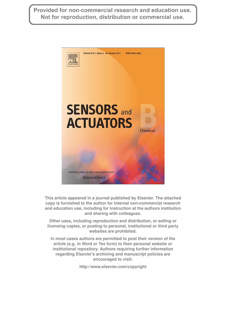
Fig. 1. Microfluidic chip demonstrating the implementation of multiplexed peristaltic pumps. The four fluid channel lines (FL, blue) are each controlled by their own peristalticpump connected to control channels or pumping lines (PL, green), which in turn are each controlled by their own multiplexing channel lines (ML, yellow). The circles representexternal pneumatic connections for the corresponding pumping and multiplexing lines. (a) The chip at rest, with no multiplexing lines actuated. Actuation of the pumpinglines would result in fluid flow in all four fluid lines. (b) The chip with two multiplexing lines (ML-B and ML-D) actuated, as indicated in red, which prevents the pumps ofFL-2 and FL-4 from being actuated. The pumping lines now can only actuate two of the four pumps (as indicated with dark green), allowing for fluid to be pumped only inFL-1 and FL-3 (dark blue). (For interpretation of the references to color in this figure caption, the reader is referred to the web version of the article.)
cuits. Liu et al. [12] used three buffer streams with different pHvalues to control several pH-responsive hydrogel valves, whileVyawahare et al. [13] used thin wires made of shape memoryalloys to control multiple valves and peristaltic pumps with a sin-gle wire. However, these non-pneumatically actuated valves andpumps are not as versatile as their pneumatic-equivalents in termsof compatibility with on-chip processes and ease of integration intohigh-density microfluidic networks. One of the earliest microfluidicmultiplexers for pneumatic valves was reported by Thorsen et al.[14], who developed a binary multiplexer to address 2n/2 valveswith n external connections (control lines). This binary microflu-idic multiplexer has since been used in several applications wherea high-density microfluidic chip was required, such as gene expres-sion [15], protein crystallization [16] and combinatorial chemistry[17]. In order to further improve the binary multiplexer, Lee andCho [18] developed ternary and quaternary multiplexers for pneu-matic valves by using more than one threshold value for the valveactuation pressure, as opposed to a single threshold pressure usedin a binary multiplexer. This ternary and quaternary multiplexingscheme allowed control of 3n/2 and 4n/2 valves, respectively, usingonly n control lines. The first example of multiplexing of the valvelines or the control lines, instead of the fluid channels, was reportedby Kawai et al. [19]. Their approach allowed the number of exter-nal pneumatic connections required to actuate 2n/2 valves to bereduced from n (as in the case of traditional binary multiplexers)to 2log2n + 2.
Although several examples of microfluidic multiplexers forpneumatic valves have been described in the literature, no reportsof similar multiplexers for pneumatic pumps exist. Peristalticpumps, which comprise of a series of pneumatic valves (3 ormore valves each), are most commonly used in microfluidics [7].Although these peristaltic pumps transport fluids at lower flowrates (approximately 1 nL/s) compared to the traditional syringepumps (greater than 10 nL/s), the peristaltic pumps offer muchfiner, local control over the flow, both in terms of the fluid responseto the on-off switching of the pump and the precise regulation ofthe flow rate. Additionally, the peristaltic pumps can be integratedon-chip, thus reducing the external ancillaries (no syringe pumps)and the overall system size. Since each peristaltic pump comprisesof 3 or more pneumatic valves, the on-chip integration of these
pumps rapidly increases the number of control lines needed. Unfor-tunately, the on-chip peristaltic pumps require specific sequencesof valve operation that are unattainable by the various approachesfor multiplexing of valves reported previously.
In this paper, we report an approach for multiplexing pneumaticvalves that for the first time allows for a large number of peri-staltic pumps to be controlled with a limited number of externalpneumatic connections. Whereas some of the previously reportedapproaches for the multiplexing of microfluidic valves requirethree-layer assemblies [19], the microfluidic chips with multi-plexed peristaltic pumps reported here can be assembled from onlytwo layers, thus greatly simplifying chip fabrication and assembly.We demonstrate the utility of these multiplexed peristaltic pumpsin a microfluidic chip that integrates droplet-generation and rout-ing capabilities. We also specify a set of design rules for integrationof multiplexed peristaltic pumps in microfluidic chips.
2. Design of multiplexed peristaltic pumps
2.1. Design of multiplexed peristaltic pumps
A microfluidic peristaltic pump typically consists of a series ofthree or more pneumatic valves placed in parallel over a single fluidchannel [7]. Individual pneumatic valves consist of a thin mem-brane, which separates a layer that contains the fluid channel anda layer that contains the control channel (see Fig. S1 in supple-mentary information). The application of pneumatic pressure inthe control channel deflects the membrane into the fluid channel,which stops the flow. Sequential actuation of the pneumatic valvesin a peristaltic pump results in pumping action and unidirectionalmotion of fluid in the fluid channel (see Fig. S2 in the supplemen-tary information for a typical sequence). A single peristaltic pumprequires individual pneumatic connections to an external pneu-matic controller for each of its valves. Hence, the number of pumpsthat can be integrated on a single chip will be limited by the numberof pneumatic connections available from the ancillary equipment.
To reduce these scaling limitations, we propose a novelapproach for the multiplexing of pneumatic valves that enables theintegration of multiplexed peristaltic pumps as shown in Fig. 1(a).The chip consists of four microfluidic fluid channel lines (FL, blue,

Author's personal copy
386 M.C. Cole et al. / Sensors and Actuators B 151 (2011) 384–393
1–4 in the figure) each being driven by its own 3-valve peristalticpump that is operated by control channels or pumping lines (PL,green). Note that all four sets of the pumping valves are connectedto the same pneumatic inlet, i.e. the first valve for each pump is con-nected to one inlet, and so on for the second and third valves (or forany additional valves that may be present in a given pump). A setof four multiplexing channel lines (ML, yellow, A–D in the figure)is routed across all the pumping lines. Each multiplexing line hasmultiplexing valves that can selectively close off the three pump-ing lines associated with the peristaltic pump of a given fluid line.At the same time, the multiplexing line will not affect the pumpinglines associated with the pumps of the other fluid lines, because thesections of the multiplexing line that intersect the unrelated pump-ing lines are designed to be as thin as possible. Consequently, thesurface area of the membrane between the fluid channel and thecontrol channel is small, so the membrane will not deflect com-pletely at the pressures normally used to actuate the valves. Forexample, opening or closing multiplexing line A (ML-A) will openor close only the pumping lines for fluid line 1 (FL-1), and so on.
Fig. 1(a) shows the chip at rest, with none of the multiplexinglines actuated. Actuation of the pumping lines would result in fluidflow in all four fluid lines. Fig. 1(b) shows the multiplexed opera-tion of the peristaltic pumps. In this configuration, ML-B and ML-Dare actuated or closed, which implies that the peristaltic pumpinglines for FL-2 and FL-4 are also closed, and hence the peristalticpumps cannot pump fluid in those channels. However, ML-A andML-C are open, so when the pumping lines are actuated with a typ-ical pumping sequence, the valves for FL-1 and FL-3 will pump fluidin those channels. The multiplexing scheme shown in Fig. 1 reducesthe number of required external pneumatic connections from 12,in case of a non-multiplexed configuration, to 7, in case of the mul-tiplexing approach introduced here. Later, we will elaborate on thegeneral scaling rules of this multiplexing approach.
The multiplexing configuration shown in Fig. 1 is achieved in anactual microfluidic chip by the assembly of two layers. The upperlayer contains the control channels or the pumping channels thatoperate push-down valves (those that form the peristaltic pumps),and the lower layer contains the fluid channels, as well as themultiplexing channels that operate push-up valves to select whichpumps are to be actuated (Fig. 2). For clarity of illustration, only asingle valve of a pumping channel (i.e. part of each peristaltic pump)and a single valve of a multiplexing channel are shown. This two-layer fabrication approach could also be used for the much simplerfabrication and assembly of the previously reported chips based onthree-layer fabrication [19].
A key design feature of the multiplexing approach introducedhere is the use of push-up valves in the multiplexing channelsto selectively close different sets of pumping channels, and theuse of push-down valves that form the peristaltic pumps associ-ated with the different fluid channels. Not only does this approachreduce the number of layers required to create the multiplexingconfiguration from three to two, it also reduces the actuation pres-sure needed in the multiplexing lines. Simultaneous actuation ofthe pumping lines and the multiplexing lines is required for themultiplexed operation of the peristaltic pumps. Therefore, the actu-ation pressure in the multiplexing lines (pML) has to be largerthan that in the pumping lines (pPL), so that pML is high enoughto close the multiplexing valves while acting against pPL. For thegeometries and dimensions used here, a pressure difference ofapproximately 20 psi is required to close the push-down valves ofthe peristaltic pumps. Thus, a pressure of 40 psi would be neededto actuate the multiplexing valves to overcome the pressure in thepumping lines. However, push-up valves require lower actuationpressures compared to push-down valves due to the differencesin the geometry of the valve and the channel (see supplementaryinformation) [20]. Here, the multiplexing valves are designed to be
Fig. 2. Schematic illustration of the integration of push-down and push-up valvesinto a single two-layer chip. The lower fluid layer contains the fluid channels, as wellas the multiplexing channels that operate push-up valves to select which pumps areto be actuated. The upper layer contains the control channels (pumping channels)that operate the push-down valves of the pumps. This approach enables the mul-tiplexing approach introduced here, which involves selective actuation of differentperistaltic pumps.
push-up valves, so a pML of only 30 psi is needed to close the valvescompletely.
2.2. Key aspects of the multiplexing approach for peristalticpumps
The multiplexing approach introduced here allows for a signif-icant reduction in the number of external pneumatic connectionsnecessary to operate a given configuration of peristaltic pneumaticpumps. In a traditional non-multiplexed configuration of peristalticpumps (NMP), the number of connections needed, NNMP, would be
NNMP = Npumps × Nvalves, (1)
where Npumps is the number of peristaltic pumps in the chip andNvalves is the number of valves used per pump. In contrast, the mul-tiplexing approach introduced here (MP) reduces the number ofexternal connections, NMP, to
NMP = Npumps + Nvalves. (2)
The difference between NMP and NNMP will become more sig-nificant when the number of pumps and the valves per pump ina microfluidic chip increases. Our proof-of-principle chip consistsof 4 pumps with 3 valves per pump, so 12 pneumatic connec-tions would have been needed for a non-multiplexed configuration,whereas only 7 connections are needed in the multiplexed designshown in Fig. 1. Upon increasing the complexity of the chip to 10pumps comprising of 4 valves each, NNMP would be 40, whereas NMP
would be only 14 for the multiplexing approach introduced here.Apart from requiring fewer external pneumatic connections,
the multiplexing approach introduced here offers two additionaladvantages. Firstly, the multiplexing channels are integrated in thesame layer as the fluid channels, thereby reducing the number oflayers from three to two. This reduction in number of layers greatlyfacilitates the assembly of high-density microfluidic chips contain-ing multiplexed pumps and valves. Secondly, due to the fact that

Author's personal copy
M.C. Cole et al. / Sensors and Actuators B 151 (2011) 384–393 387
the corresponding valves of multiple peristaltic pumps are con-nected to the same pneumatic inlet, a single actuation sequence ofthe pumping lines results in simultaneous operation of all the con-nected pumps. Furthermore, in our multiplexed design, individualpumps can rapidly be switched on/off by actuation of only a sin-gle multiplexing line. In contrast, a non-multiplexed configurationwould require each valve of each pump to be actuated individually.As a result, the operation of multiple pumps using our multiplexingapproach is significantly simplified from a software (programming)and hardware (time required for execution of a single command)point of view, compare to the non-multiplexed configuration. Thissimplification becomes particularly important for the operation ofchips with a large number of pumps and valves.
Multiplexing of peristaltic pumps can also be implementedusing the previously reported binary multiplexing approach forindividual valves [14]. However, the multiplexing approach intro-duced here can address valves of multiple peristaltic pumpssimultaneously (parallel operation), whereas the conventionalbinary multiplexing approach can address each valve of each pumpsequentially (serial operation). The latter is much more opera-tionally intensive, which becomes an issue especially in caseswhere many pumps need to be actuated in short periods of time.The advantage gained by the exponential decrease of externalconnections for the conventional (serial) multiplexing approachcompared to the additive decrease of external connections forthe (parallel) multiplexing approach introduced here, is offset byreduced throughput in large microfluidic networks, where simul-taneous operation of or switching between multiple peristalticpumps is required.
One drawback to the multiplexing approach introduced here isthat sets of multiplexed pumps can only be operated in a ‘singlemode’ at a time. The interconnected pumps are all actuated usingthe same sequence, so fluid flow will be at an identical rate andin the same direction. However, this drawback can be overcome byperforming the desired actuations sequentially (e.g. different pumpcycle rates) while switching between different multiplexing lines,so fluid flow in different fluid lines can be controlled independently,with the only sacrifice being a reduced throughput (e.g. serial versusparallel operation of multiple pumps).
3. Fabrication of the multiplexed peristaltic pumps
The fabrication procedure for the multiplexed valve design(Fig. 2) is schematically illustrated in Fig. 3. The fabrication processfor the multiplexed valve design followed the typical procedurefor multilayer soft lithography for PDMS-based microfluidics [7],except that here, different channel functionalities were integratedin the same layer using different photoresists.
First, the 35-�m thick multiplexing channels were patterned ona silicon wafer using negative photoresist (SU-8 50) via standardlithographic techniques. The negative resist yields channels withvertical sidewalls and rectangular cross-sections, as is necessaryfor complete closure of the push-up valves [20]. Next, 12-�m thickfluid channels were patterned on the same wafer using positivephotoresist (SJR-5740). The positive photoresist was heated to justabove its glass transition temperature to reflow the resist, result-ing in a rounded semi-circular cross-section for the fluid channels(Fig. 3(a)). This semi-circular profile is needed to ensure that thepush-down valves completely seal off the fluid channel [7].
On a second silicon wafer, the 35-�m thick control or pump-ing channels of the control layer were patterned using a different,more viscous positive photoresist (50XT) than that used for thefluid channels. To create the rounded profile, the positive resist wasreflowed by heating to just above its glass transition temperature.Conventionally in multilayer PDMS chips, the control channels are
Fig. 3. Fabrication procedure for the two-layer multiplexed valve structure shownin Fig. 2. (a) Positive relief masters (photoresist on silicon) for the two layers. Thefluid layer consists of the rectangular multiplexing channels patterned using nega-tive photoresist, and the rounded fluid channels patterned using reflowed positivephotoresist. The control layer consists of the control or pumping channels patternedusing thick reflowed positive photoresist. (b) Replica molding of the masters: a thinlayer of PDMS was spun on the master for the fluid layer, while a thick layer of PDMSwas poured on the master for the control layer. (c) After curing the PDMS, the thickPDMS control layer was lifted off its master and aligned and bonded to the PDMSpattern of the underlying fluid master layer. Subsequently, this combined mold wasbonded and sealed against a glass substrate to form the structure shown in Fig. 2.
patterned using negative photoresist. However, positive photore-sist was used to pattern the control channels here to obtain roundedchannels after reflow, because the multiplexing valves need to beable to close of these channels (pumping channels) through push-up valve architectures.
After photoresist patterning and reflow, a silane monolayer wasevaporated onto the masters to prevent the adhesion of PDMS to thesilicon substrates. Next, a thin layer of PDMS was spun on the mas-ter for the fluid layer, while a thick layer of PDMS was poured on themaster for the control layer. After curing the PDMS, the thick PDMScontrol layer was lifted off its master, aligned to the thin PDMSpattern of the underlying fluid master layer, and bonded usingstandard procedures for multilayer soft lithography [7]. Finally, thetwo-layer PDMS assembly was bonded to a glass substrate, afteractivation of the surfaces using plasma, to form the structure shownin Fig. 2. Further details of the fabrication procedure are providedin the supplementary information.
4. Application of the multiplexed peristaltic pumps inmicrofluidic chips
4.1. Characterization of the peristaltic pumps
First, we characterized the individual peristaltic pumps withrespect to valve geometry and valve spacing to arrive at anoptimized configuration that will result in maximum fluid displace-ment rate (flow rate). For this purpose, we created a microfluidicchip for the manipulation of two-phase flows. Specifically, we usedperistaltic pumps to merge an aqueous and an oil stream at a T-junction to generate a two-phase flow comprised of water dropletsin an oil stream. Further details of the droplet-generation are pro-

Author's personal copy
388 M.C. Cole et al. / Sensors and Actuators B 151 (2011) 384–393
Fig. 4. Characterization of peristaltic pumps: flow rate as a function of (a) the num-ber of valves per peristaltic pump and (b) the spacing between individual valves,with the number of valves fixed at three.
vided in the supplementary information. We first studied the effectof the number of valves (varied from 3 to 5) in a peristaltic pumpon the flow rate in 125 �m wide and 12 �m tall fluid channels.The valves of the peristaltic pumps were 150 �m wide, 35 �m tall,and spaced apart by 150 �m. The flow rate was measured opticallyunder a microscope by tracking the position of a droplet over time.
Fig. 4(a) shows the plot of flow rate versus actuation frequency,the rate at which the individual valves in the peristaltic pumps areopened and closed (as opposed to the rate for an entire pumpingcycle), for peristaltic pumps comprised of 3, 4, or 5 valves. A max-imum flow rate of 1.7 nL/s was observed for the 5-valve pump atan actuation frequency of 4 Hz. For all three pumps, the flow ratesincreased as the actuation frequency increased, until the flow ratesbegan to saturate at approximately 5 Hz. This saturation behavior isdue to the fact that the dynamic deflection of the valve membranecan no longer follow the actuation frequency, which results in atransfer of lesser volume of fluid for a partially closed valve. Thissaturation behavior is in agreement with the predictions of pre-viously reported analytical models for these types of microfluidicconfiguration [21–23]. We also observed no measurable flow rateat frequencies higher than 10 Hz, which is again a typical character-istic of the frequency response of peristaltic pumps [7,21–23]. Theflow rate increases with increasing number of valves, due to thefact that the volume of fluid advanced per cycle also increases [22].Although higher number of valves result in higher flow rates, theadditional valves results in an increase in the size of the chip andalso the number of required external connections. Hence, the finalnumber of valves in a single pump will depend on the requirementsand space constraints of the end-application.
Next, we studied the effect of valve spacing on the flow rate, withthe number of valves per pump fixed at three. The fluid channelswere 125 �m wide and 12 �m tall, while the pumping valves were150 �m wide and 35 �m tall. The spacing between the valves was
varied between 90, 150, and 210 �m, to result in ratios of valvespacing to valve width of 0.6, 1, and 1.4, respectively. We define thisratio as the spacing factor. Fig. 4(b) shows a graph of the flow rate asa function of actuation frequency for the three pumps with differentspacing factors. The same trend as in Fig. 4(a) is observed, in thatthe flow rate increases with increasing valve frequency, saturates atapproximately 5 Hz, and drops to zero for frequencies on the orderof 10 Hz.
In addition, the results shown in Fig. 4(b) indicate that the flowrates are higher when the gap between the valves in a pump isless than the size of the valves themselves. The peristaltic pump-ing mechanism relies on the fact that the entire downstream fluidline will be advanced by a volume of liquid equal to the volumedirectly underneath a valve, when that valve is deflected down-ward. However, these pumps are fabricated out of PDMS, which isa soft elastomeric material and can be easily deformed. Therefore,when a valve is actuated, the volume of the liquid displaced notonly moves the fluid column but deforms the PDMS channel wallsas well. Liquid in the channel far away from the actuated valve willbe unaffected, because some of the displaced volume will be used todeform the PDMS, before it slowly relaxes back to its original state.The farther the valves are spaced apart within a peristaltic pump,the less of the actual liquid volume displacement is transferred tothe next valve, resulting in lower flow rates.
4.2. Implementation of multiplexed peristaltic pumps in amicrofluidic chip
After characterizing the operation of individual peristalticpumps, we used the 2-layer multiplexing approach described inSection 2 (Fig. 1) to create a microfluidic chip with multiplexedperistaltic pumps shown in Fig. 5. This chip consists of two fluidlines (FL-1 and FL-2), each being driven by its own multiplexed 3-valve peristaltic pump (blue), which in turn are each controlled byseparate multiplexing lines (ML-A and ML-B). The fluid lines andthe multiplexing lines are molded in the thinner lower PDMS layer,while the pumping lines are molded in the thicker upper layer,following the 2-layer approach described in Section 3 (Fig. 3). Thecenter column of images in Fig. 5 shows the entire chip for threedifferent stages of the valve actuation – parts (a), (b), and (c) –while the magnified images on the left and right show close-upviews of the pumping valves and multiplexing valves, respectively.Each individual control line, either a multiplexing or a pumping line,was actuated using a single dedicated solenoid valve connected to asingle external pressure source. A dedicated solenoid valve for eachcontrol line allows for independent actuation of the control lines, asis required for the operation of peristaltic pumps and for choosingan arbitrary set of peristaltic pumps using the multiplexing schemediscussed here.
In Fig. 5(a), none of the valves are actuated and all fluid linesare open. In Fig. 5(b), ML-B has been actuated by applying a pres-sure of 30 psi, thereby closing its three valves which restrict flowin the underlying pumping lines associated with FL-2. In Fig. 5(c),the three pumping lines have been actuated by applying a pres-sure of 20 psi, while the valves on ML-B are still closed, so only thepumping valves of FL-1 are actuated (closed), while the valves ofthe peristaltic pump on FL-2 remain unaffected (open). Note thatthe 10 psi net difference in the actuation pressures for the pumpingand multiplexing lines is sufficient to completely close the push-upmultiplexing valves, as discussed in Section 2.2. A video showingthe multiplexed operation of this chip, fluid being pumped in FL-2, but not FL-1 because ML-B has been actuated, is provided assupplementary material. The selective actuation of one set of peri-staltic pumping valves of a set of two, of which all valves are connectedto common pneumatic inlets, demonstrates one of the key aspects ofthe multiplexing design introduced here. In this example of 2 multi-

Author's personal copy
M.C. Cole et al. / Sensors and Actuators B 151 (2011) 384–393 389
Fig. 5. Microfluidic chip to demonstrate the operation of multiplexed peristaltic pumps. The fluid lines (FL-1 and FL-2) and the multiplexing lines (ML-A and ML-B), renderedcolorless in figure, were molded in the lower PDMS layer. The pumping lines (blue) were molded in the thicker upper layer. (a) All the valves and all the lines are open. (b)ML-B is actuated (represented by a red cross through one of its valves), thereby closing off the pumping lines beneath it. (c) All the pumping lines are actuated, allowing thevalves of the pump for FL-1 to also be actuated, while ML-B remains closed, so the valves of the pump in FL-2 remain unaffected. (For interpretation of the references to colorin this figure caption, the reader is referred to the web version of the article.)
plexed pumps, the number of external connections is only reducedby 1 (5 instead of 6), but, as explained in Section 2, the differ-ence between the required number of external connections for amultiplexed and a non-multiplexed chip rapidly increases with anincreasing number of peristaltic pumps and valves within a singlechip.
4.3. A microfluidic chip with integrated multiplexed peristalticpumps for routing of droplets
Next, we demonstrated the application of multiplexed peri-staltic pumps in a microfluidic chip designed to generate and routedroplets. In recent years, droplet-based microfluidics have receivedincreased attention in the fields of biological and chemical syn-thesis and analysis, due to the advantages of efficient mixing,reduced dispersion of reagents, and the ability to perform paral-lel experiments. These advantages and the many applications ofdroplet-based microfluidics have been discussed in detail in recentreview articles [24–27]. The microfluidic chip (Fig. 6) for routingdroplets consists of two droplet-generating T-junctions, capableof introducing droplets of two different liquids to a main inletchannel that leads into a 3 × 3 node channel array. The 3 × 3 arrayis connected to 11 routing channels, where each routing chan-nel is actuated by its own 4-valve peristaltic pump. The pumpsare used to advance the droplets along the vertical and horizon-tal channels within the array. The dimensions of the pumps arethe same as the peristaltic pumps discussed in Section 4.1, witha spacing factor of 1. These 11 pumps are arranged into 3 groupsof multiplexed pumps, thereby reducing the number of external
connections necessary for those pumps from 44 to 23. The peri-staltic pumps used for droplet-generation via the T-junctions werenot multiplexed, because droplet-generation does require that thepumps drive the water and oil streams at different rates simul-taneously, which is less straightforward using our multiplexingapproach, as discussed in Section 2. However, in systems for rout-ing droplets in larger arrays, the number of pumps needed fordroplet-generation will be small compared to the number neededfor routing droplets. Consequently, the loss in efficiency caused byusing non-multiplexed pumps for droplet-generation will not besignificant.
Fig. 6 shows a schematic illustration of the design and thefabrication procedure for the microfluidic chip. The chip was fab-ricated using the two-layer fabrication procedure discussed inSection 3, but with slight differences, which are discussed in thesupplementary information. The resulting chip is shown in Fig. 7,with all channel/lines filled with a differently dyed solution to aidin visualization: fluid channels are red, multiplexing channels blue,droplet-generating pumps yellow, and the multiplexed pumps pur-ple.
To demonstrate the capabilities of the multiplexed peristalticpumps in an integrated microfluidic system, the chip shown inFig. 7 was used to generate discrete liquid droplets, and then routethese droplets through the 3 × 3 channel array. Optical micro-graphs of a single droplet’s path at different instants of time areshown in Fig. 8. A water droplet (dyed orange) was generated in acarrier oil stream (FC 40) using the standard approach for droplet-generation via a T-junction in a two-phase flow [28]. Details ofthe generation of droplets using a T-junction are provided in the

Author's personal copy
390 M.C. Cole et al. / Sensors and Actuators B 151 (2011) 384–393
Fig. 6. Channel layout and fabrication procedure for the microfluidic chip designed to generate and route droplets. (a) The fluid layer master consists of the multiplexingchannels (blue) and the inlet fluid channels (also blue) patterned first using 35-�m SU-8 (negative photoresist), followed by the fluid channel array (red) patterned next using12-�m SJR-5740 (positive photoresist). The control layer master consists of the peristaltic pumping channels and valves for the generation of droplets (yellow) patternedfirst using 35-�m SU-8, and the multiplexed peristaltic pumping channels (maroon) patterned next using 35-�m AZ 50XT (positive photoresist). (b) Schematic illustrationof the completed chip fabricated by assembly and alignment of a spin-coated thin layer of PDMS replicating the fluid layer master (∼50 �m) and a thicker, replica-moldedPDMS layer of the control layer. (For interpretation of the references to color in this figure caption, the reader is referred to the web version of the article.)
Fig. 7. Optical micrograph of the PDMS-based microfluidic chip to generate and route droplets. The red fluid channels and the blue multiplexing channels with push-upvalves were molded in the thinner lower PDMS layer. The multiplexed peristaltic pumping channels with push-down valves (purple) and the droplet-generation pumpingchannels with push-down valves (yellow) were molded in the thicker upper PDMS layer. (For interpretation of the references to color in this figure caption, the reader isreferred to the web version of the article.)
Author's personal copy
M.C. Cole et al. / Sensors and Actuators B 151 (2011) 384–393 391
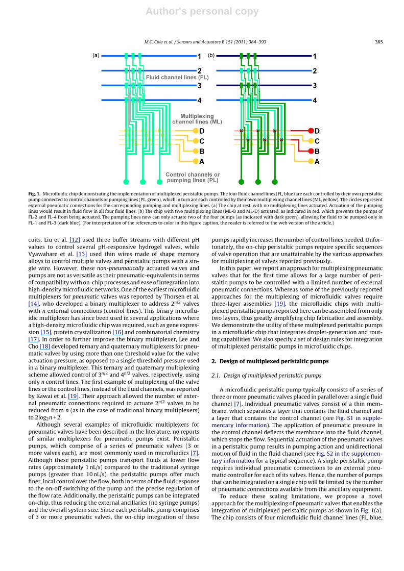
Fig. 8. Optical micrographs of a water droplet (orange) being manipulated through the droplet-routing chip. Red arrows indicate that a given pump is pumping in thedirection of the arrow. Blue arrows indicate the position and direction of the droplet. The orange color of the water droplet has been enhanced in the figure for clarity. (a)The water droplet is introduced into the 3 × 3 array using the upstream oil pump and Pumps 3 and 8. (b) The droplet continues through the array using the concerted actionof Pumps 1, 3 and 8. (c) The droplet reached the bottom right corner and Pump 8 was switched off. (d) Pump 9 was switched on to drive the droplet upward, along the rightside of the array. (e) When the droplet was past the corner, Pump 8 was switched back on, now pumping in the opposite direction, along with Pump 11. (f–h) The dropletreached the next intersection and was driven out of the array (toward the right) by the concerted actuation of Pumps 1, 3, 8, 9 and 11. (For interpretation of the referencesto color in this figure caption, the reader is referred to the web version of the article.)
supplementary information. The water droplet is advanced fromthe droplet-generation section to the 3 × 3 node array by drivingthe upstream oil pump in the droplet-generation section (whichcan be seen in Fig. 7), along with the inward and outward pumpingof multiplexed Pumps 3 and 8, respectively, which can be seen inFig. 8(a).
In Fig. 8(b), the droplet has entered the 3 × 3 array, and Pump1 was switched on to help drive the droplet towards the right. InFig. 8(c), the droplet has reached the lower right node, and mustbe directed upward, instead of being allowed to continue alongits current straight path. At this point, Pump 8 (the pump near-est to the droplet) was switched off. In Fig. 8(d), the droplet was

Author's personal copy
392 M.C. Cole et al. / Sensors and Actuators B 151 (2011) 384–393
advanced around the corner and up the right side of the array byswitching on Pump 9. Once the droplet cleared the intersection,Pump 8 was switched back on, and pumped inward, along withPump 11 (Fig. 8(e)). When the droplet reached the next intersec-tion in Fig. 8(f), the flow generated from Pump 1 forced the dropletto again change directions. Fig. 8(g) and (h) shows the droplet beingpushed towards the outlet channel under Pump 7, and then finallyout of the array. At this point another droplet could be introducedinto the array and similarly routed to other locations on the grid.Fig. 8 clearly demonstrates the utility of the multiplexed peristalticpumps to perform complex operations on a single integrated chip. Avideo of the droplet-routing experiment shown in Fig. 8 is providedas supplementary material.
5. Design rules for integration of multiplexed peristalticpumps
Key design rules for integration and operation of multiplexedperistaltic pumps in high-density microfluidic chips emerged fromthe experiments described above are as follows:
1. The multiplexing design for peristaltic pumps shown in Fig. 1 willreduce the number of required external pneumatic connectionsfrom Npumps × Nvalves for a non-multiplexed configuration (NNMP)to Npumps + Nvalves for the multiplexed approach (NMP) introducedhere. Npumps and Nvalves denote, respectively, the number of peri-staltic pumps and valves used per pump in the microfluidic chip.By comparison of NNMP and NMP, one can decide whether or notto implement a multiplexing approach at the expense of a lessintuitive channel network design and associated fabrication.
2. The sections of the pumping lines that connect the valves of theperistaltic pumps to the pneumatic inlet (green lines in Fig. 1)need to be as thin as possible because they cross other fluidlines between actuation valves, thereby setting a lower limitto the valve-to-valve spacing. As discussed in Section 4.1, themaximum achievable flow rate decreases upon increasing thedistance between adjacent valves of a peristaltic pump. Hence,these thin sections of the pumping lines should be made as nar-row as possible, within the limits of the fabrication procedure.
3. Push-up valves should be used for the multiplexing lines andpush-down valves for the pumping lines, and not vice-versa, toallow for the multiplexed chip to be fabricated using only twolayers. Furthermore, as already specified in Section 2, the lowerrequired pressure for actuation of push-up valves reduces therequired pressure for actuation of the multiplexing lines from>40 to 30 psi.
4. Typically, the use of peristaltic pumps comprised of 4 valves ispreferable over 3-valve pumps in heavily multiplexed microflu-idic networks. Pumping lines have to cross in-between adjacentvalves of multiplexed peristaltic pumps. The reduced perfor-mance due to the increased valve-to-valve spacing can becompensated by increasing the number of valves per pump, asdiscussed in Section 4.1. Note that the number of multiplexedpumps per set is limited, because for each additional pump, anadditional pumping line has to cross between the valves of theother peristaltic pumps within the same multiplexed set.
6. Conclusions
In this paper, we introduced a novel multiplexing approachfor integration and operation of pneumatic peristaltic pumps inmicrofluidic chips. The multiplexing approach greatly reduces thenumber of external pneumatic connections required for the oper-ation of sets of peristaltic pumps, which is important for thedevelopment of ever more complex VLSI microfluidic chips. Wedemonstrated the utility of multiplexed peristaltic pumps by gen-
erating and routing droplets in a 3 × 3 microfluidic array. Theimplementation of both push-up valves and push-down valveswithin the same chip enabled integration of two of the three nec-essary channel networks, the multiplexing lines and the fluid lines,in a single layer. As a result, these multiplexed microfluidic chipscan be obtained by alignment and assembly of just two microflu-idic molds. This simplified soft-lithographic fabrication procedurefacilitates integration of multiple sets of multiplexed pumps intocomplex microfluidic chips, because the fabrication proceduresminimizes alignment issues associated with the assembly of chipscomprised of 3 or more layers.
Many parameters can have a profound effect on the performanceof individual peristaltic pumps, as well as on multiplexed sets ofthese pumps. We characterized the performance (i.e. achievableflow rates) of individual peristaltic pumps as a function of the num-ber of valves and valve-to-valve spacing. We expressed the resultsof this study in a set of design rules for the integration and opera-tion of multiplexed peristaltic pumps in high-density microfluidicchips. The multiplexing approach reported here may find applica-tion in a wide range of microfluidic chips for chemical and biologicalapplications, especially those that require the integration of manydifferent operations on a single chip and those that need to performsimilar operations massively in parallel in sub-nanoliter volumes.
Acknowledgements
We gratefully acknowledge financial support from the NationalScience Foundation under awards CMMI 03-28162 and CMMI07-49028 to Nano-CEMMS; a NanoScience & Engineering Center(NSEC) on Nanomanufacturing. We also acknowledge the financialsupport from the Department of Energy (DOE) through the NationalInstitute for NanoEngineering (NINE) initiative of the Lab DirectedResearch and Development (LDRD) program at Sandia NationalLaboratories. Profilometry was carried out in the Frederick SeitzMaterials Research Laboratory Central Facilities, University of Illi-nois, which is supported in part by the U.S. Department of Energyunder grants DE-FG02-07ER46453 and DE-FG02-07ER46471.
Appendix A. Supplementary data
Supplementary data associated with this article can be found, inthe online version, at doi:10.1016/j.snb.2010.07.012.
References
[1] R.G. Blazej, P. Kumaresan, R.A. Mathies, Microfabricated bioprocessor for inte-grated nanoliter-scale Sanger DNA sequencing, Proceedings of the NationalAcademy of Sciences 103 (2006) 7240–7245.
[2] C.-C. Lee, G. Sui, A. Elizarov, C.J. Shu, Y.-S. Shin, A.N. Dooley, J. Huang, A. Daridon,P. Wyatt, D. Stout, H.C. Kolb, O.N. Witte, N. Satyamurthy, J.R. Heath, M.E. Phelps,S.R. Quake, H.-R. Tseng, Multistep synthesis of a radiolabeled imaging probeusing integrated microfluidics, Science 310 (2005) 1793–1796.
[3] R. Pal, M. Yang, R. Lin, B.N. Johnson, N. Srivastava, S.Z. Razzacki, K.J. Chomistek,D.C. Heldsinger, R.M. Haque, V.M. Ugaz, P.K. Thwar, Z. Chen, K. Alfano, M.B.Yim, M. Krishnan, A.O. Fuller, R.G. Larson, D.T. Burke, M.A. Burns, An integratedmicrofluidic device for influenza and other genetic analyses, Lab on a Chip 5(2005) 1024–1032.
[4] C.B. Rohde, F. Zeng, R. Gonzalez-Rubio, M. Angel, M.F. Yanik, Microfluidic systemfor on-chip high-throughput whole-animal sorting and screening at subcellu-lar resolution, Proceedings of the National Academy of Sciences 104 (2007)13891–13895.
[5] H. Suzuki, R. Yoneyama, Integrated microfluidic system with electrochemicallyactuated on-chip pumps and valves, Sensors and Actuators B: Chemical 96(2003) 38–45.
[6] R. Zengerle, J. Ulrich, S. Kluge, M. Richter, A. Richter, A bidirectional siliconmicropump, Sensors and Actuators A: Physical 50 (1995) 81–86.
[7] M.A. Unger, H.P. Chou, T. Thorsen, A. Scherer, S.R. Quake, Monolithic microfab-ricated valves and pumps by multilayer soft lithography, Science 288 (2000)113–116.
[8] K.W. Oh, R. Rong, C.H. Ahn, Miniaturization of pinch-type valves and pumps forpractical micro total analysis system integration, Journal of Micromechanicsand Microengineering 15 (2005) 2449–2455.

Author's personal copy
M.C. Cole et al. / Sensors and Actuators B 151 (2011) 384–393 393
[9] G. Waibel, J. Kohnle, R. Cernosa, M. Storz, M. Schmitt, H. Ernst, H. Sandmaier,R. Zengerle, T. Strobelt, Highly integrated autonomous microdosage system,Sensors and Actuators A: Physical 103 (2003) 225–230.
[10] W.H. Grover, R.H.C. Ivester, E.C. Jensen, R.A. Mathies, Development andmultiplexed control of latching pneumatic valves using microfluidic logicalstructures, Lab on a Chip 6 (2006) 623–631.
[11] K.W. Oh, C.H. Ahn, A review of microvalves, Journal of Micromechanics andMicroengineering 16 (2006) R13–R39.
[12] C. Liu, J.Y. Park, Y. Xu, S. Lee, Arrayed pH-responsive microvalves controlled bymultiphase laminar flow, Journal of Micromechanics and Microengineering 17(2007) 1985–1991.
[13] S. Vyawahare, S. Sitaula, S. Martin, D. Adalian, A. Scherer, Electronic control ofelastomeric microfluidic circuits with shape memory actuators, Lab on a Chip8 (2008) 1530–1535.
[14] T. Thorsen, S.J. Maerkl, S.R. Quake, Microfluidic large-scale integration, Science298 (2002) 580–584.
[15] J.F. Zhong, Y. Chen, J.S. Marcus, A. Scherer, S.R. Quake, C.R. Taylor, L.P. Weiner, Amicrofluidic processor for gene expression profiling of single human embryonicstem cells, Lab on a Chip 8 (2008) 68–74.
[16] C.L. Hansen, M.O.A. Sommer, S.R. Quake, Systematic investigation of proteinphase behavior with a microfluidic formulator, Proceedings of the NationalAcademy of Sciences of the United States of America 101 (2004) 14431–14436.
[17] G.A. Cooksey, C.G. Sip, A. Folch, A multi-purpose microfluidic perfusion systemwith combinatorial choice of inputs, mixtures, gradient patterns, and flow rates,Lab on a Chip 9 (2009) 417–426.
[18] D.W Lee, Y.-H. Cho, High-radix microfluidic multiplexer with pressure valvesof different thresholds, Lab on a Chip 9 (2009) 1681–1686.
[19] K. Kawai, Y. Shibata, M. Kanai, S. Shoji, Multiplexed pneumatic valve controlsystem for large scale integrated microfluidic circuit (LSIMC), in: Twelfth Inter-national Conference on Miniaturized Systems for Chemistry and Life Sciences,San Diego, California, USA, 2008, pp. 683–685.
[20] V. Studer, G. Hang, A. Pandolfi, M. Ortiz, W.F. Anderson, S.R. Quake, Scalingproperties of a low-actuation pressure microfluidic valve, Journal of AppliedPhysics 95 (2004) 393–398.
[21] F. Goldschmidtboing, A. Doll, M. Heinrichs, P. Woias, H.J. Schrag, U.T. Hopt,A generic analytical model for micro-diaphragm pumps with active valves,Journal of Micromechanics and Microengineering 15 (2005) 673–683.
[22] J. Goulpeau, D. Trouchet, A. Ajdari, P. Tabeling, Experimental study and model-ing of polydimethylsiloxane peristaltic micropumps, Journal of Applied Physics98 (2005) 044914–44919.
[23] J. Xie, J. Shih, Q. Lin, B. Yang, Y.-C. Tai, Surface micromachined electrostaticallyactuated micro peristaltic pump, Lab on a Chip 4 (2004) 495–501.
[24] G.F. Christopher, S.L. Anna, Microfluidic methods for generating continu-ous droplet streams, Journal of Physics D: Applied Physics 40 (2007) R319–R336.
[25] A. Huebner, S. Sharma, M. Srisa-Art, F. Hollfelder, J.B. Edel, A.J. deMello, Micro-droplets: a sea of applications? Lab on a Chip 8 (2008) 1244–1254.
[26] H. Song, D.L. Chen, R.F. Ismagilov, Reactions in droplets in microfluidic channels,Angewandte Chemie International Edition 45 (2006) 7336–7356.
[27] S.-Y. Teh, R. Lin, L.-H. Hung, A.P. Lee, Droplet microfluidics, Lab on a Chip 8(2008) 198–220.
[28] T. Thorsen, R.W. Roberts, F.H. Arnold, S.R. Quake, Dynamic pattern formationin a vesicle-generating microfluidic device, Physical Review Letters 86 (2001)4163.
Biographies
Matthew C. Cole received his MS and PhD degrees in Chemical & BiomolecularEngineering from the University of Illinois, Urbana-Champaign. His research focusedon the development of sensing and routing platforms for microchemical systemscomprised of large arrays of microfluidic channels. In December 2008 he joined theBrady Corporation in Milwaukee, WI.
Amit V. Desai received his BTech and MTech degrees in Mechanical Engineeringfrom the Indian Institute of Technology (IIT), Bombay, and his PhD degree in Mechan-ical and Nuclear Engineering from the Pennsylvania State University, UniversityPark in the field of nanomechanics. He is currently a post-doctoral researcher inUniversity of Illinois, Urbana-Champaign, where his research focuses on the appli-cation of microfluidic technologies for life-sciences and biomedical applications, anddevelopment of electrostatic valves for integrated microfluidics.
Paul J.A. Kenis received his PhD in Chemical Engineering from Twente University,The Netherlands and is currently an associate professor of Chemical & Biomolec-ular Engineering at the University of Illinois with affiliate appointments in theBeckman Institute, the Institute for Genomic Biology, the Frederick Seitz Materialresearch Laboratory, the Micro- & Nanotechnology Laboratory, and the departmentof Mechanical Science & Engineering. His research efforts include the develop-ment of microchemical systems: membraneless microfuel cells, microreactors forsynthesis (e.g. radiolabeling of biomolecules), microfluidic chips for pharmaceu-tical and (membrane) protein crystallization, platforms for biological cell studies(regenerative biology), sensors and valves for integrated microfluidic networks, andmicro/nanofluidic tools for nanomanufacturing.
Related Documents


