arXiv:1012.0401v1 [physics.optics] 2 Dec 2010 Two-dimensional point spread matrix of layered metal-dielectric imaging elements Rafa l Koty´ nski, 1,* Tomasz Antosiewicz, 2 Karol Kr´ ol, 1 and Krassimir Panajotov 3,4 1 Faculty of Physics, University of Warsaw, Pasteura 7, 02-093 Warsaw, Poland 2 Interdisciplinary Centre for Mathematical and Computational Modelling, University of Warsaw, Pawinskiego 5A, 02-106 Warsaw, Poland 3 Department of Applied Physics and Photonics, Vrije Universiteit Brussel, Pleinlaan 2, 1050 Brussels, Belgium 4 Institute of Solid State Physics, 72 Tzarigradsko Chaussee Blvd. 1784, Sofia, Bulgaria * [email protected] We describe the change of the spatial distribution of the state of polarisation occurring during two-dimensional imaging through a multilayer and in particular through a layered metallic flat lens. Linear or circular polarisation of incident light is not preserved due to the difference in the amplitude transfer functions for the TM and TE polarisations. In effect, the transfer function and the point spread function that characterize 2D imaging through a multilayer both have a matrix form and cross-polarisation coupling is observed for spatially modulated beams with a linear or circular incident polarisation. The point spread function in a matrix form is used to characterise the resolution of the superlens for different polarisation states. We demonstrate how the 2D PSF may be used to design a simple diffractive nanoelement consisting of two radial slits. The structure assures the separation of non-diffracting radial beams originating from two slits in the mask and exhibits an interesting property of a backward power flow in between the two rings. c 2013 Optical Society of America OCIS codes: 160.4236 , 050.0050, 110.0110 , 260.0260 , 310.6628, 100.6640 1. INTRODUCTION In 2000, Pendry [1] showed that a simple silver slab is capable of imaging in the near-field with resolution beyond the diffraction limit for the near-UV wavelength range. The operation of a similar but asymmetric [2] flat lens was later experimentally verified [3, 4]. In these works, the mechanism leading to super-resolution is related to the appearance of a surface plasmon polariton (SPP) mode, which enables transfer of the evanescent part of the spatial spectrum through the slab. Other ways of achieving superlensing include the use of photonic crystals showing negative refraction [5–9]. Both losses and the cut-off wavelength of the SPP mode limit the operation range to sub-wavelength distances only [10,11]. This obstacle has been tackled to some degree in several ways. One of them is by breaking the silver slab into a metallic multilayer [2,12] with effective anisotropic properties and strong coupling of the SPP modes between neighbouring layers. Otherwise the loss may be compensated by the use of media with gain [13,14]. Notably, according to the the effective medium model, a layered lens is approximated with a uniaxially anisotropic uniform slab [12]. Uniaxial 1

Welcome message from author
This document is posted to help you gain knowledge. Please leave a comment to let me know what you think about it! Share it to your friends and learn new things together.
Transcript
arX
iv:1
012.
0401
v1 [
phys
ics.
optic
s] 2
Dec
201
0
Two-dimensional point spread matrix of layered metal-dielectric
imaging elements
Rafa l Kotynski,1,∗ Tomasz Antosiewicz,2 Karol Krol,1 and Krassimir Panajotov3,4
1Faculty of Physics, University of Warsaw, Pasteura 7, 02-093 Warsaw, Poland
2Interdisciplinary Centre for Mathematical and Computational Modelling, University of Warsaw,
Pawinskiego 5A, 02-106 Warsaw, Poland
3Department of Applied Physics and Photonics, Vrije Universiteit Brussel, Pleinlaan 2, 1050 Brussels,
Belgium
4Institute of Solid State Physics, 72 Tzarigradsko Chaussee Blvd. 1784, Sofia, Bulgaria
We describe the change of the spatial distribution of the state of polarisation occurring
during two-dimensional imaging through a multilayer and in particular through a layered
metallic flat lens. Linear or circular polarisation of incident light is not preserved due to
the difference in the amplitude transfer functions for the TM and TE polarisations. In
effect, the transfer function and the point spread function that characterize 2D imaging
through a multilayer both have a matrix form and cross-polarisation coupling is observed
for spatially modulated beams with a linear or circular incident polarisation. The point
spread function in a matrix form is used to characterise the resolution of the superlens
for different polarisation states. We demonstrate how the 2D PSF may be used to design
a simple diffractive nanoelement consisting of two radial slits. The structure assures the
separation of non-diffracting radial beams originating from two slits in the mask and
exhibits an interesting property of a backward power flow in between the two rings. c©2013 Optical Society of America
OCIS codes: 160.4236 , 050.0050, 110.0110 , 260.0260 , 310.6628, 100.6640
1. INTRODUCTION
In 2000, Pendry [1] showed that a simple silver slab is capable of imaging in the near-field with resolution
beyond the diffraction limit for the near-UV wavelength range. The operation of a similar but asymmetric [2]
flat lens was later experimentally verified [3, 4]. In these works, the mechanism leading to super-resolution
is related to the appearance of a surface plasmon polariton (SPP) mode, which enables transfer of the
evanescent part of the spatial spectrum through the slab. Other ways of achieving superlensing include the
use of photonic crystals showing negative refraction [5–9]. Both losses and the cut-off wavelength of the SPP
mode limit the operation range to sub-wavelength distances only [10, 11]. This obstacle has been tackled to
some degree in several ways. One of them is by breaking the silver slab into a metallic multilayer [2,12] with
effective anisotropic properties and strong coupling of the SPP modes between neighbouring layers. Otherwise
the loss may be compensated by the use of media with gain [13, 14]. Notably, according to the the effective
medium model, a layered lens is approximated with a uniaxially anisotropic uniform slab [12]. Uniaxial
1
SrTiO3 Ag SrTiO3 Ag SrTiO3 Ag SrTiO3 Ag SrTiO3
INCI
DEN
CE P
LANE
OUT
PUT
PLAN
E
L=N ·�
�
dSrTiO3/2 dSrTiO3dAg
z
x
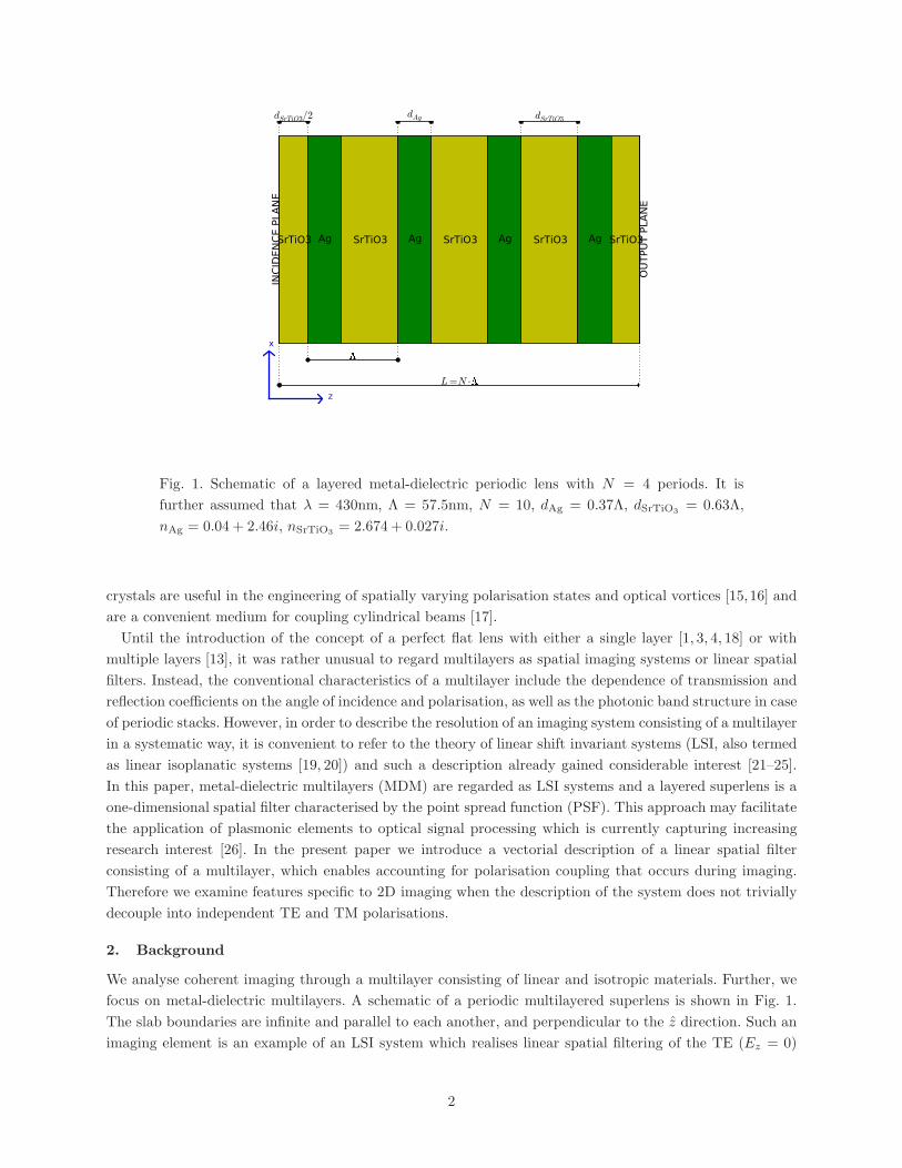
Fig. 1. Schematic of a layered metal-dielectric periodic lens with N = 4 periods. It is
further assumed that λ = 430nm, Λ = 57.5nm, N = 10, dAg = 0.37Λ, dSrTiO3= 0.63Λ,
nAg = 0.04 + 2.46i, nSrTiO3= 2.674 + 0.027i.
crystals are useful in the engineering of spatially varying polarisation states and optical vortices [15,16] and
are a convenient medium for coupling cylindrical beams [17].
Until the introduction of the concept of a perfect flat lens with either a single layer [1, 3, 4, 18] or with
multiple layers [13], it was rather unusual to regard multilayers as spatial imaging systems or linear spatial
filters. Instead, the conventional characteristics of a multilayer include the dependence of transmission and
reflection coefficients on the angle of incidence and polarisation, as well as the photonic band structure in case
of periodic stacks. However, in order to describe the resolution of an imaging system consisting of a multilayer
in a systematic way, it is convenient to refer to the theory of linear shift invariant systems (LSI, also termed
as linear isoplanatic systems [19, 20]) and such a description already gained considerable interest [21–25].
In this paper, metal-dielectric multilayers (MDM) are regarded as LSI systems and a layered superlens is a
one-dimensional spatial filter characterised by the point spread function (PSF). This approach may facilitate
the application of plasmonic elements to optical signal processing which is currently capturing increasing
research interest [26]. In the present paper we introduce a vectorial description of a linear spatial filter
consisting of a multilayer, which enables accounting for polarisation coupling that occurs during imaging.
Therefore we examine features specific to 2D imaging when the description of the system does not trivially
decouple into independent TE and TM polarisations.
2. Background
We analyse coherent imaging through a multilayer consisting of linear and isotropic materials. Further, we
focus on metal-dielectric multilayers. A schematic of a periodic multilayered superlens is shown in Fig. 1.
The slab boundaries are infinite and parallel to each another, and perpendicular to the z direction. Such an
imaging element is an example of an LSI system which realises linear spatial filtering of the TE (Ez = 0)
2
or TM (Hz = 0) -polarised incident wavefunction. Notably, diffraction in air and propagation through a
metallic or dielectric slab are simple examples of linear spatial filters of the incident field, while a layered
superlens is a more sophisticated one and may be seen as a superposition of such simpler systems, however
it is still a linear spatial filter. From an engineering perspective, multiple degrees of freedom of a multilayer
provide some leeway to perform point spread function optimisation of the response of the spatial filter. The
distribution of scalar electric or magnetic field components in the plane of incidence Ψ(x, y)z=zincand an
output plane Ψ(x, y)z=zout, with a layered structure in between, are related through a convolution relation
with the two-dimensional point spread function H(x, y),
Ψ(x, y)z=zout= (2π)−1H(x, y) ∗Ψ(x, y)z=zinc
. (1)
Here ∗ denotes a two-dimensional convolution and we assume that propagation is in the z direction. The
same relation transformed to the domain of spatial harmonics provides the definition of the transfer function
(TF) which we denote as H,
Ψ(kx, ky)z=zout= H(kx, ky) · Ψ(kx, ky)z=zinc
, (2)
where the hat represents the two-dimensional unitary Fourier transform, defined as
Ψ(x, y)z = (2π)−1
∫ ∫
Ψ(kx, ky)z ei(kxx+kyy)dkxdky . (3)
The PSF, related to the TF through the spatial Fourier transform, provides precise information on reshaping
of the optical signal due to diffraction combined with multiple reflections and refractions, and is direct and
convenient to interpret. Resolution of the system depends on the bandwidth of the transmitted spatial
spectrum and super-resolution in the near field occurs when the transfer function of the system does not
vanish for the evanescent part of the spatial spectrum (k2x > 1).
Until now, we assumed that the system is scalar. This is only true when the field is purely TE or TM-
polarised or when the transfer function is the same for the TE or TM polarisations which basically occurs
only for simple propagation in air. There exist at least two important situations when the field symmetry
in our system decouples Maxwell’s equations into these two polarisation states. One takes place for in-plane
imaging (e.g. in the x− z plane) of 1D field distributions, when imaging of scalar fields (Hy(x), Ex(x), Ez(x))
and (Ey(x), Hx(x), Hz(x)) are independent and stand for the TM and TE polarisations, respectively. The
other important situation takes place for a cylindrical beam with the angular wavenumber equal to m = 0,
when the radial (Er(r), Hφ(r), Ez(r)) and angular (Hr(r), Eφ(r), Hz(r)) polarisations are also examples of
pure TM and TE polarisations. In both situations, the symmetry of the system requires that the incident
field is only one-dimensional with the dependence on either x or r. More complex incident field distributions
are neither TE or TM polarised and due to the different transfer function for the TE and TM polarisations,
are subject to a change in the polarisation state during imaging through a multilayer.
3. 2D imaging properties of layered systems in 3D
At a plane z = z0, a monochromatic field is characterised by two polarisation components. For in-
stance, for the linear or circular polarisation these are Ex(x, y)z=z0 and Ey(x, y)z=z0 , or Eσ+(x, y)z=z0 and
Eσ−
(x, y)z=z0 , respectively.
Initially, let us assume knowledge of the one-dimensional transfer function (TF) for the TE and TM
polarisations, denoting them as HTE(kx) and HTM (kx), respectively. These TFs may be easily determined
using the transfer matrix method from the complex transmission coefficients of propagating and evanescent
planewaves with the wavevector components in the x− z plane. We introduce denotations for the mean and
3
difference of these two TFs, Hm = (HTM + HTE)/2, and Hδ = (HTM −HTE)/2, which are more convenient
for the description of 2D imaging.
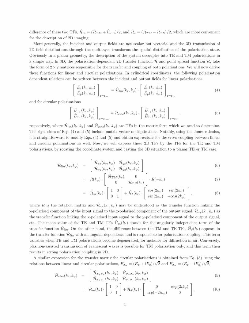
More generally, the incident and output fields are not scalar but vectorial and the 3D transmission of
2D field distributions through the multilayer transforms the spatial distribution of the polarisation state.
Obviously in a planar geometry, the description of the system decouples into TE and TM polarisations in
a simple way. In 3D, the polarisation-dependent 2D transfer function H and point spread function H, take
the form of 2× 2 matrices responsible for the transfer and coupling of both polarisations. We will now derive
these functions for linear and circular polarisations. In cylindrical coordinates, the following polarisation
dependent relations can be written between the incident and output fields for linear polarisations,[
Ex(kr, kϕ)
Ey(kr, kϕ)
]
z=zout
= Hlin(kr, kϕ) ·[
Ex(kr, kϕ)
Ey(kr, kϕ)
]
z=zin
, (4)
and for circular polarisations[
Eσ+(kr, kϕ)
Eσ−
(kr , kϕ)
]
z=zout
= Hcirc(kr, kϕ) ·[
Eσ+(kr, kϕ)
Eσ−
(kr , kϕ)
]
z=zin
, (5)
respectively, where Hlin(kr, kϕ) and Hcirc(kr , kϕ) are TFs in the matrix form which we need to determine.
The right sides of Eqs. (4) and (5) include matrix-vector multiplications. Notably, using the Jones calculus,
it is straightforward to modify Eqs. (4) and (5) and obtain expressions for the cross-coupling between linear
and circular polarisations as well. Now, we will express these 2D TFs by the TFs for the TE and TM
polarisations, by rotating the coordinate system and casting the 3D situation to a planar TE or TM case,
Hlin(kr, kϕ) =
[
Hxx(kr, kϕ) Hyx(kr, kϕ)
Hxy(kr, kϕ) Hyy(kr, kϕ)
]
(6)
= R(kϕ) ·[
HTM (kr) 0
0 HTE(kr)
]
· R(−kϕ) (7)
= Hm(kr) ·[
1 0
0 1
]
+ Hδ(kr) ·[
cos(2kϕ) sin(2kϕ)
sin(2kϕ) −cos(2kϕ)
]
, (8)
where R is the rotation matrix and Hxx(kr, kϕ) may be understood as the transfer function linking the
x-polarised component of the input signal to the x-polarised component of the output signal, Hxy(kr , kϕ) as
the transfer function linking the x-polarised input signal to the y-polarised component of the output signal,
etc. The mean value of the TE and TM TFs Hm(kr) stands for the angularly independent term of the
transfer function Hlin. On the other hand, the difference between the TM and TE TFs, Hδ(kr) appears in
the transfer function Hlin with an angular dependence and is responsible for polarisation coupling. This term
vanishes when TE and TM polarisations become degenerated, for instance for diffraction in air. Conversely,
plasmon-assisted transmission of evanescent waves is possible for TM polarisation only, and this term then
results in strong polarisation coupling in 2D.
A similar expression for the transfer matrix for circular polarisations is obtained from Eq. (8) using the
relations between linear and circular polarisations, Eσ+= (Ex + iEy)/
√2 and Eσ
−
= (Ex − iEy)/√2,
Hcirc(kr , kϕ) =
[
Hσ+σ+(kr , kϕ) Hσ
−σ+
(kr , kϕ)
Hσ+σ−
(kr, kϕ) Hσ−σ−
(kr, kϕ)
]
(9)
= Hm(kr) ·[
1 0
0 1
]
+ Hδ(kr) ·[
0 exp(2ikϕ)
exp(−2ikϕ) 0
]
, (10)
4
In order to derive the corresponding 2D point spread functions, we will use the following decomposition for
the 2D Fourier transform of a function separable in the angular coordinate system. For g(r, ϕ) = gr(r)·gϕ(ϕ),the corresponding Fourier transform g(kr , kϕ) is equal to [20],
g(kr , kϕ) =
+∞∑
n=−∞
(−i)ncn · exp(inkϕ) · Hn {gr(r)} , (11)
where, the expansion coefficients cn are equal to
cn =
∫ 2π
0
gϕ(ϕ) · exp(−inϕ)dϕ, (12)
and Hn denotes the n-th order Hankel transform,
Hn {gr(r)} =
∫
∞
0
gr(r) · Jn(krr) · r · dr. (13)
This decomposition leads to the following expressions for the polarisation-dependent 2D point spread
function of the layered system,
Hlin(r, ϕ) =
[
Hxx(r, ϕ) Hyx(r, ϕ)
Hxy(r, ϕ) Hyy(r, ϕ)
]
(14)
= Hm(r) ·[
1 0
0 1
]
−Hδ(r) ·[
cos(2ϕ) sin(2ϕ)
sin(2ϕ) −cos(2ϕ)
]
(15)
Hcirc(r, ϕ) =
[
Hσ+σ+(r, ϕ) Hσ
−σ+
(r, ϕ)
Hσ+σ−
(r, ϕ) Hσ−σ−
(r, ϕ)
]
(16)
= Hm(r) ·[
1 0
0 1
]
−Hδ(r) ·[
0 exp(2iϕ)
exp(−2iϕ) 0
]
(17)
where Hm(r) = H0
{
Hm(kr)}
and Hδ(r) = H2
{
Hδ(kr)}
.
Summarising, the numerical calculation of the point spread functions in 2D requires the following steps:
1. finding the 1D TE and TM transfer functions for a planar geometry using the transfer matrix method,
2. determination of the 1D Hankel transforms of the 0-th and 2-nd orders of the mean and difference of these
two TFs, respectively. 3. Reconstruction of the point spread functions (15) and (17) including the angular
dependence. Therefore, the majority of the numerical calculations is done in 1D. While we evaluate directly
the Hankel transforms, it should be noted that there exist fast numerical algorithms which may be applied
instead [27]. The 0-th order Hankel transform links the rotationally invariant part of PSF to the respective
rotationally invariant part of TF, which in turn is equal to the average of TE and TM one-dimensional TFs.
On the other hand, the difference of the TM and TE one-dimensional TFs is responsible for the angularly
dependent polarisation coupling and is related to the respective part of the point spread function through
the second order Hankel transform.
4. Polarisation coupling for linearly or circularly polarised incident beams
In this section we calculate the TF-matrix and PSF-matrix for two-dimensional vectorial spatial filtering
realized with a layered lens. We assume that the lens consists of silver and strontium titanate with a filling
fraction of silver equal to 0.37 and operates at a wavelength of λ = 430nm. The structure is presented in
5
a)
0 1 2 3 4 5kx /k0
�20
�15
�10
�5
0
5Am
plitu
de [d
B]Transfer Function (1D)
HTM
HTE
Hair
�4
�3
�2
�1
0
1
Phas
e [�
]
0.0 0.1 0.2 0.3 0.4 0.5x/�
0.0
0.2
0.4
0.6
0.8
1.0
Ampl
itude
[a.u
.]
Point Spread Function (1D)
HTM
HTE
Hair
�0.20.00.20.40.60.81.01.21.41.6
Phas
e [�
]
b)
0 1 2 3 4 5kr/k0
�20
�15
�10
�5
0
5
Ampl
itude
[dB]
Transfer Function (2D)
Hm
H�
Hair
�2.5�2.0�1.5�1.0�0.50.00.51.01.5
Phas
e [�
]
0.0 0.1 0.2 0.3 0.4 0.5r/�
0.0
0.2
0.4
0.6
0.8
1.0
Ampl
itude
[a.u
.]
Point Spread Function (2D)
Hm
H�
Hair
0.0
0.5
1.0
1.5
2.0
Phas
e [�
]
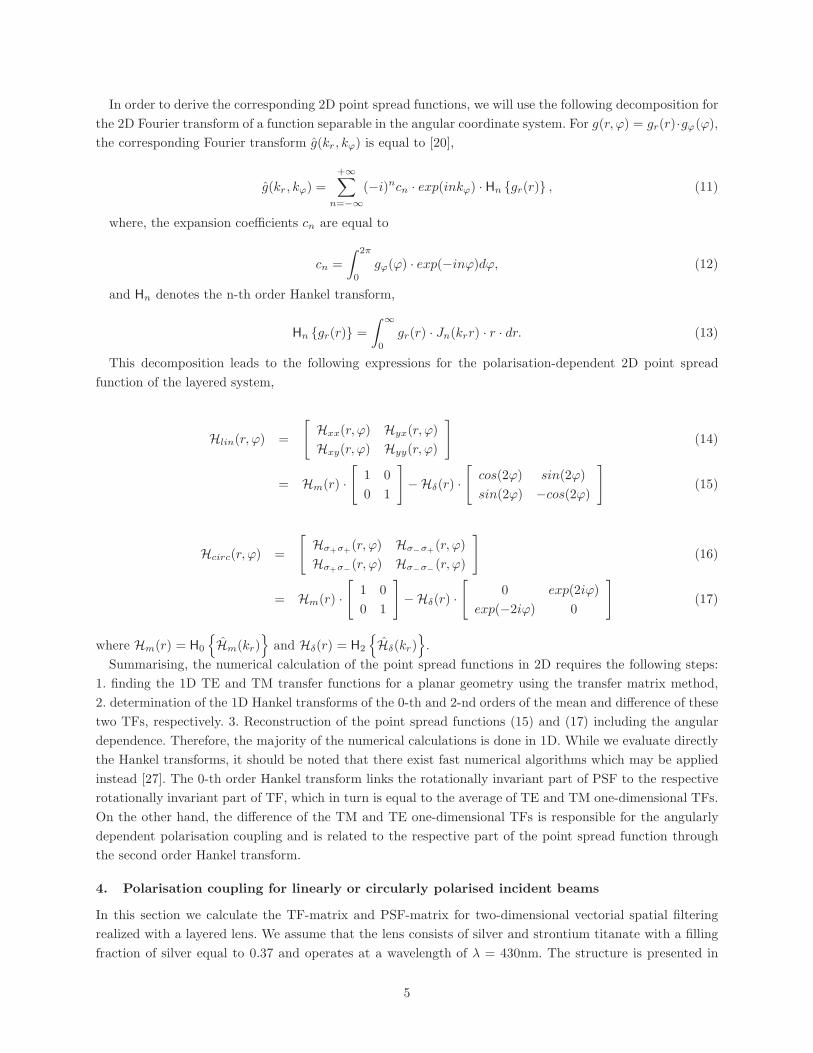
Fig. 2. a) One-dimensional TF and PSF of the multilayer for in-plane propagation:
HTM ,HTE – TF for the TM and TE polarisations; b) Radial cross-section of two-
dimensional TF and PSFs of the multilayer for 3D propagation Hm = (HTM + HTE)/2,
Hδ = (HTM − HTE)/2. 1D and 2D PSFs and TF corresponding to propagation in air for
the same distance are also shown for comparison. Solid lines and dashed lines represent the
amplitudes and phases of the respective complex functions.
Fig. 1. It is a low-loss self-guiding superlens with a sub-wavelength FWHM of PSF for the TM polarisation in
the order of λ/10 and it has been already thoroughly investigated in terms of transmission efficiency as well
as of resolution for in-plane imaging [23,25]. The elementary cell consists of an Ag layer symmetrically coated
with SrTiO3. Strontium titanate is an isotropic material with a high refractive index n = 2.674 + 0.027i at
λ = 430nm [28]. The refractive index of silver at the same wavelength is equal to nAg = 0.04 + 2.46i [29].
Further, we assume that the multilayer consists of N = 10 periods with a thickness of Λ = 57.5nm each.
In Fig. 2 in the top row we show the phase (dashed lines) and amplitude (solid lines) of the TFs:
HTM (x),HTE(x), Hm(kr), Hδ(r), and the TF for propagation in air at the same distance. In the bottom row,
the corresponding 1D PSF and the radial part of the 2D PSF are also presented. Our example illustrates some
of the general properties of the TF - for normal incidence (kx = 0), we have HTM (0) = HTE(0) = Hm(0), and
Hδ(r) = 0. On the other hand, for evanescent harmonics SPPs are only supported for the TM polarisation
and therefore for a sufficiently large kx we have |HTM (kx)| >> |HTE(kx)|, and in effect 2HTM ≈ Hm ≈ Hδ.
Therefore, the bandwidth and asymptotic behaviour of Hm and Hδ are the same as of HTM (see the solid line
in Fig. 2b, top for kr/k0 > 1.8). If the bandwidth of HTM extends to kx >> 1 and its phase is approximately
constant, which are the necessary conditions for super-resolution, the same properties are also satisfied by
Hm and Hδ. Therefore, we expect to see super-resolution in 2D, even though 2D-imaging depends on both
TE and TM polarisations and the TE polarisation itself does not allow for super-resolution. This observation
is confirmed by the shape of 2D PSF presented in the same figure. We further see (the violet line in Fig. 2b,
bottom) that the polarisation coupling determined by Hδ is zero at r = 0 and smoothly increases with kr
reaching a maximum at r/λ ∼ 0.18 i.e. at (approximately) the first minimum of Hm.
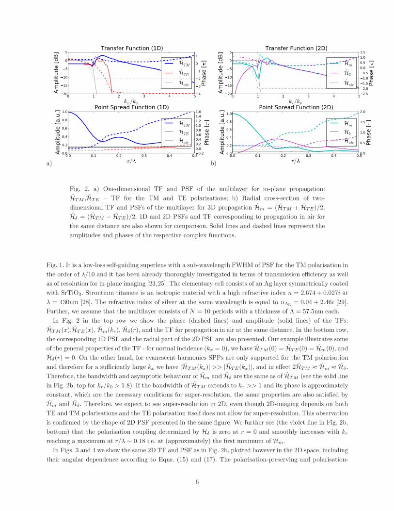
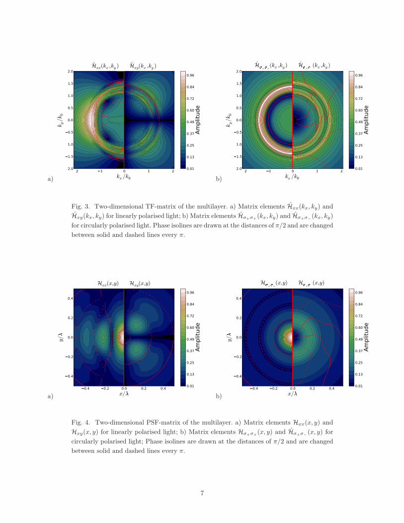
In Figs. 3 and 4 we show the same 2D TF and PSF as in Fig. 2b, plotted however in the 2D space, including
their angular dependence according to Eqns. (15) and (17). The polarisation-preserving and polarisation-
6
a)
�2 �1 0 1 2kx /k0
�2.0
�1.5
�1.0
�0.5
0.0
0.5
1.0
1.5
2.0
ky/k0
Hxx(kx ,ky ) Hxy(kx ,ky )
0.01
0.13
0.25
0.37
0.49
0.60
0.72
0.84
0.96
Ampl
itude
b)
2 1 0 1 2kx /k0
2.0
1.5
1.0
0.5
0.0
0.5
1.0
1.5
2.0
ky/k0
H++(kx ,ky ) H+�
(kx ,ky )
0.01
0.13
0.25
0.37
0.49
0.60
0.72
0.84
0.96
Ampl
itude
Fig. 3. Two-dimensional TF-matrix of the multilayer. a) Matrix elements Hxx(kx, ky) and
Hxy(kx, ky) for linearly polarised light; b) Matrix elements Hσ+σ+(kx, ky) and Hσ+σ
−
(kx, ky)
for circularly polarised light. Phase isolines are drawn at the distances of π/2 and are changed
between solid and dashed lines every π.
a)
�0.4 �0.2 0.0 0.2 0.4x/
�0.4
�0.2
0.0
0.2
0.4
y/
�
Hxx(x,y) Hxy(x,y)
0.01
0.13
0.25
0.37
0.49
0.60
0.72
0.84
0.96
Ampl
itude
b)
�0.4 �0.2 0.0 0.2 0.4x/�
�0.4
�0.2
0.0
0.2
0.4
y/
�
H�+�+(x,y) H�+��
(x,y)
0.01
0.13
0.25
0.37
0.49
0.60
0.72
0.84
0.96
Ampl
itude
Fig. 4. Two-dimensional PSF-matrix of the multilayer. a) Matrix elements Hxx(x, y) and
Hxy(x, y) for linearly polarised light; b) Matrix elements Hσ+σ+(x, y) and Hσ+σ
−
(x, y) for
circularly polarised light; Phase isolines are drawn at the distances of π/2 and are changed
between solid and dashed lines every π.
7
a)
�0.4 �0.2 0.0 0.2 0.4x/�
�0.4
�0.2
0.0
0.2
0.4
y/
�
�(Ex ·H �y ) �(H �
x ·Ey )
-0.00
0.12
0.24
0.36
0.48
0.60
0.72
0.84
0.96
Long
itudi
nal p
ower
flow
Pz
b)
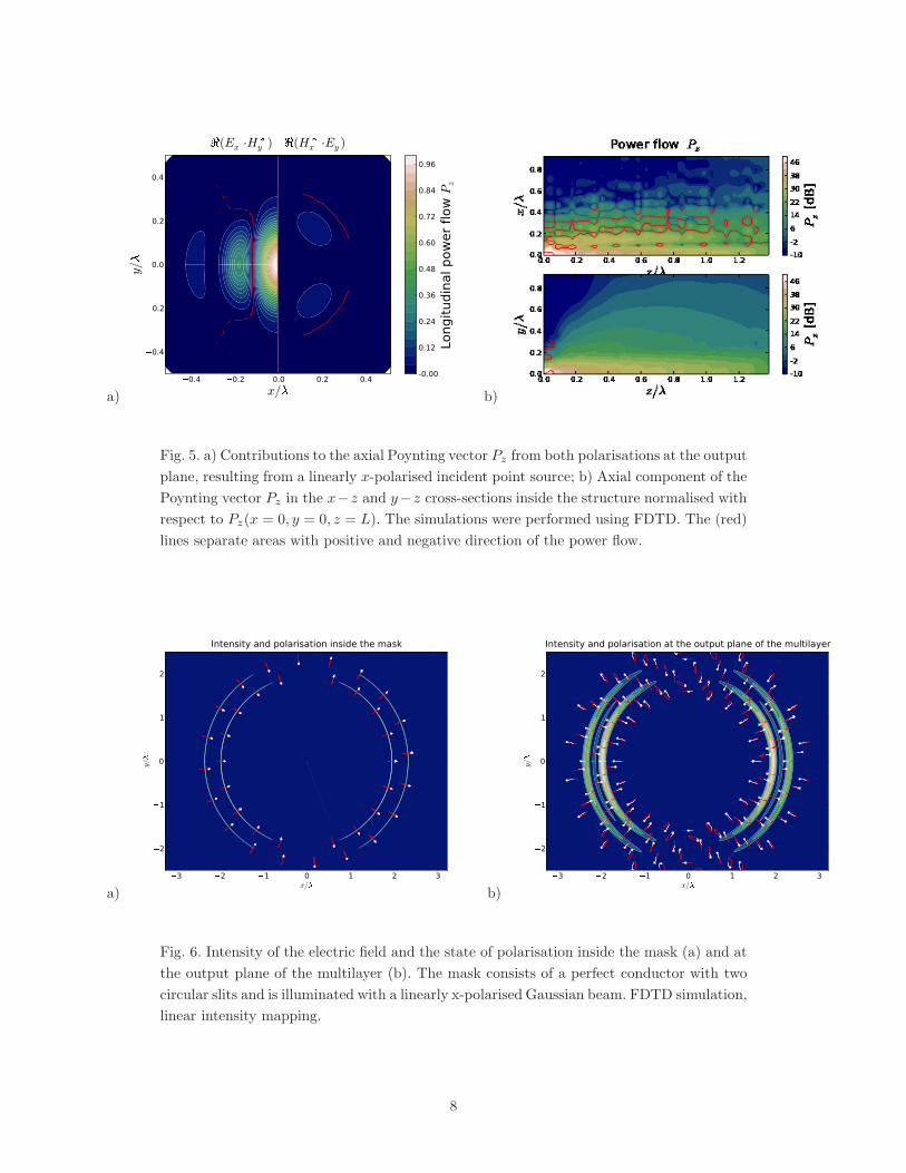
Fig. 5. a) Contributions to the axial Poynting vector Pz from both polarisations at the output
plane, resulting from a linearly x-polarised incident point source; b) Axial component of the
Poynting vector Pz in the x−z and y−z cross-sections inside the structure normalised with
respect to Pz(x = 0, y = 0, z = L). The simulations were performed using FDTD. The (red)
lines separate areas with positive and negative direction of the power flow.
a)
�3 �2 �1 0 1 2 3x/�
�2
�1
0
1
2
y/
�
Intensity and polarisation inside the mask
b)
�3 �2 �1 0 1 2 3x/�
�2
�1
0
1
2
y/
�
Intensity and polarisation at the output plane of the multilayer
Fig. 6. Intensity of the electric field and the state of polarisation inside the mask (a) and at
the output plane of the multilayer (b). The mask consists of a perfect conductor with two
circular slits and is illuminated with a linearly x-polarised Gaussian beam. FDTD simulation,
linear intensity mapping.
8
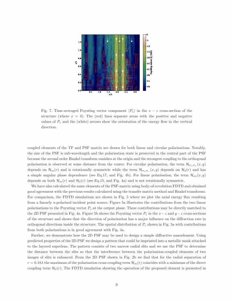
Fig. 7. Time-averaged Poynting vector component 〈Pz〉 in the x − z cross-section of the
structure (where x = 0). The (red) lines separate areas with the positive and negative
values of Pz and the (white) arrows show the orientation of the energy flow in the vertical
direction.
coupled elements of the TF and PSF matrix are drawn for both linear and circular polarisations. Notably,
the size of the PSF is sub-wavelength and the polarisation state is preserved in the central part of the PSF
because the second order Hankel transform vanishes at the origin and the strongest coupling to the orthogonal
polarisation is observed at some distance from the center. For circular polarisation, the term Hσ+σ+(x, y)
depends on Hm(r) and is rotationally symmetric while the term Hσ+σ−
(x, y) depends on Hδ(r) and has
a simple angular phase dependence (see Eq.17, and Fig. 4b). For linear polarisation, the term Hxx(x, y)
depends on both Hm(r) and Hδ(r) (see Eq.15, and Fig. 4a) and is not rotationally symmetric.
We have also calculated the same elements of the PSF-matrix using body-of-revolution FDTD and obtained
good agreement with the previous results calculated using the transfer matrix method and Hankel transforms.
For comparison, the FDTD simulations are shown in Fig. 5 where we plot the axial energy flux resulting
from a linearly x-polarised incident point source. Figure 5a illustrates the contributions from the two linear
polarisations to the Poynting vector Pz at the output plane. These contributions may be directly matched to
the 2D PSF presented in Fig. 4a. Figure 5b shows the Poynting vector Pz in the x−z and y−z cross-sections
of the structure and shows that the direction of polarisation has a major influence on the diffraction rate in
orthogonal directions inside the structure. The spatial distribution of Pz shown in Fig. 5a with contributions
from both polarisations is in good agreement with Fig. 4a.
Further, we demonstrate how the 2D PSF may be used to design a simple diffractive nanoelement. Using
predicted properties of the 2D PSF we design a pattern that could be imprinted into a metallic mask attached
to the layered superlens. The pattern consists of two narrow radial slits and we use the PSF to determine
the distance between the slits so that the interference between the polarisation-coupled elements of two
images of slits is enhanced. From the 2D PSF shown in Fig. 2b we find that for the radial separation of
r = 0.18λ the maximum of the polarisation cross-coupling termHm(r) coincides with a minimum of the direct
coupling term Hδ(r). The FDTD simulation showing the operation of the proposed element is presented in
9
Figs. 6 and 7. A linearly polarised Gaussian beam is diffracted on the two circular slits in the mask. For
the purpose of simplicity the mask is made of a perfect conductor (PEC) and the width of slits is equal to
4 nm which corresponds to 8 grid-points of the FDTD 2D mesh. Inside the slits the wave becomes polarised
perpendicularly to the slits. This is shown in Fig. 6a. It should be noted that inside the slits the field is
neither TE or TM polarised and Ez 6= 0, Hz 6= 0. The polarisation at the output plane is shown in Fig. 6b.
In between the images of two slits there is a local maximum of intensity resulting from the interference of the
2D PSFs with the cross-polarised term eliminated. At the external side of the images of the slits, without
interference, the cross-polarised terms of PSF are still present and the polarisation state varies considerably
with respect to that within the slits. At the same time, in between the slits, the phase shift of Hm(r) reaches
approximately π with respect to its central value, resulting in the reversal of the direction of power flow
Pz . This reversal is demonstrated in Fig. 7 which shows the cross-section of the multilayer along the x − z
axes. An inverted direction of Pz may be seen along most of the propagation distance within the multilayer,
although within the mask itself the direction of the power is clearly defined in the forward direction only.
5. Conclusion
Two-dimensional beams generally do not preserve their initial spatial distribution of the state of polarisation
after passing through a layered flat lens. This is the direct result of different transfer functions corresponding
to the TM and TE components of the spatial spectrum and the presence of both TM and TE components in
the spatial spectrum of a 2D beam. We use the framework of the theory of linear shift-invariant systems to
describe the imaging system and express the PSF 2× 2-matrix for imaging of vectorial 2D wavefronts using
the 0-th and 2-nd order Hankel transforms of planar transfer functions for the TE and TM polarisations.
We calculate the polarisation-preserving and cross-polarisation 2D PSF matrix elements of a layered
superlens showing that the resolution in 2D is of the same order as the resolution for in-plane imaging with
the TM polarisation. This comes in spite of the fact that both the TE and TM polarised spatial harmonics
take part in the 2D imaging. Moreover, cross-polarisation coupling is observed for spatially modulated beams
with a linear or circular incident polarisation.
We demonstrate how the 2D PSF may be used to design a simple diffractive nanoelement. The spatial
separation of the PSF matrix elements for polarisation-preserving and polarisation-coupled imaging is used
to design a mask that forms a wavefront which during propagation exhibits destructive interference in the
cross-polarisation term, assures the separation of non-diffracting radial beams originating from two slits in
the mask and exhibits an interesting property of a backward power flow in between the two rings. This opens
a possibility for further PSF engineering where the polarisation effects are accounted for.
Acknowledgments
We acknowledge support from the Polish research projects MNiI N N202 033237, and NCBiR N R15 0018 06
and the framework of COST MP0702 action.
References
1. J. B. Pendry, “Negative refraction makes a perfect lens,” Phys. Rev. Lett. 85, 3966–3969 (2000).
2. S. A. Ramakrishna, J. B. Pendry, D. Schurig, and D. R. Smith, “The asymmetric lossy near-perfect
lens,” J. Mod. Opt. 49, 1747–1762 (2002).
3. D. O. Melville and R. J. Blaikie, “Super-resolution imaging through a planar silver layer,” Opt. Express
13, 2127–2134 (2005).
4. N. Fang, H. Lee, C. Sun, and X. Zhang, “Sub-diffraction-limited optical imaging with a silver superlens,”
Science 308, 534–537 (2005).
10

5. M. Notomi, “Theory of light propagation in strongly modulated photonic crystals: Refractionlike be-
havior in the vicinity of the photonic band gap,” Phys. Rev. B 62, 10696–10705 (2000).
6. H. Zhang, L. Shen, L. Ran, Y. Yuan, and J. Kong, “Layered superlensing in two-dimensional photonic
crystals,” Opt. Express 14, 11178–11183 (2006).
7. C. Luo, S. G. Johnson, J. D. Joannopoulos, and J. B. Pendry, “Subwavelength imaging in photonic
crystals,” Phys. Rev. B 68, 45115 (2003).
8. A. Grbic and G. V. Eleftheriades, “Overcoming the diffraction limit with a planar left-handed
transmission-line lens,” Phys. Rev. Lett. 92, 117403 (2004).
9. H. Zhang, H. Zhu, L. Qian, and D. Fan, “Collimations and negative refractions by slabs of 2d photonic
crystals with periodically-aligned tube-type air holes,” Opt. Express 15, 3519–3530 (2007).
10. K. J. Webb, M. Yang, D. W. Ward, and K. A. Nelson, “Metrics for negative-refractive-index materials,”
Phys. Rev. E 70, 35602 (2004).
11. D. R. Smith, D. Schurig, M. Rosenbluth, S. Schultz, S. A. Ramakrishna, and J. B. Pendry, “Limitations
on subdiffraction imaging with a negative refractive index slab,” Appl. Phys. Lett. 82, 1506 (2003).
12. B. Wood, J. B. Pendry, and D. P. Tsai, “Directed subwavelength imaging using a layered metal-dielectric
system,” Phys. Rev. B 74, 115116 (2006).
13. S. A. Ramakrishna and J. B. Pendry, “Removal of absorption and increase in resolution in a near-field
lens via optical gain,” Phys. Rev. B 67, 201101 (2003).
14. E. V. Ponizovskaya and A. M. Bratkovsky, “Metallic negative index nanostructures at optical frequencies:
losses and effect of gain medium,” Appl. Phys. A 87, 161–165 (2007).
15. T. A. Fadeyeva, V. G. Shvedov, Y. V. Izdebskaya, A. V. Volyar, E. Brasselet, D. N. Neshev, A. S.
Desyatnikov, W. Krolikowski, and Y. S. Kivshar, “Spatially engineered polarization states and optical
vortices in uniaxial crystals,” Opt. Express 18, 10848–10863 (2010).
16. X. L. Wang, Y. Li, J. Chen, C. S. Guo, J. Ding, and H. T. Wang, “A new type of vector fields with
hybrid states of polarization,” Opt. Express 18, 10786–10795 (2010).
17. Q. Zhan, “Cylindrical vector beams: from mathematical concepts to applications,” Adv. in Opt. Photon.
1, 1–57 (2009).
18. S. A. Ramakrishna, J. B. Pendry, D. Schurig, D. R. Smith, and S. Schultz, “The asymmetric lossy
near-perfect lens,” J. Mod. Optics 49, 1747–1762 (2002).
19. B. Saleh and M. Teich, Fundamentals of Photonics (John Wiley & Sons, Inc, 2007), 2nd ed.
20. J. W. Goodman, Introduction to Fourier Optics (Roberts & Co Publ., 2005), 3rd ed.
21. C. P. Moore, M. D. Arnold, P. J. Bones, and R. J. Blaikie, “Image fidelity for single-layer and multi-layer
silver superlenses,” J. Opt. Soc. Am. A 25, 911–918 (2008).
22. N. Mattiucci, DAguanno, M. Scalora, M. J. Bloemer, and C. Sibilia, “Transmission function properties
for multi-layered structures: Application to super-resolution,” Opt. Express 17, 17517–17529 (2009).
23. R. Kotynski and T. Stefaniuk, “Multiscale analysis of subwavelength imaging with metal-dielectric
multilayers,” Opt. Lett. 35, 1133–1135 (2010).
24. R. Kotynski and T. Stefaniuk, “Comparison of imaging with sub-wavelength resolution in the canaliza-
tion and resonant tunnelling regimes,” J. Opt. A: Pure Appl. Opt. 11, 015001 (2009).
25. R. Kotynski, “Fourier optics approach to imaging with sub-wavelength resolution through metal-
dielectric multilayers,” Opto-Electron. Rev. 18, 366–375 (2010).
26. B. Lee, P. Lalanne, and Y. Fainman, “Plasmonic diffractive optics and imaging: feature introduction,”
Appl. Opt. 49, PD01 (2010).
27. A. W. Norfolk and E. J. Grace, “Reconstruction of optical fields with the quasi-discrete Hankel trans-
11

form,” Opt. Express 18, 10551–10556 (2010).
28. E. Palik, ed., Handbook of Optical Constants of Solids (Academic Press, 1998).
29. P. Johnson and R. Christy, “Optical constants of the noble metals,” Phys. Rev. B 6, 4370–4379 (1972).
12
Related Documents