T. Smolnicki et al. Raspodjela opterećenja u ležaju velikih dimenzija - problemi identifikacije ISSN 1330-3651 (Print), ISSN 1848-6339 (Online) UDC/UDK [620.172.21:539.374]:[621.822.6:621.879] DISTRIBUTION OF LOADS IN THE LARGE SIZE BEARING – PROBLEMS OF IDENTIFICATION Tadeusz Smolnicki, Mariusz Stańco, Damian Pietrusiak Original scientific paper Large diameter slewing bearings used in open cast machines are made of unhardened raceways. As a consequence the major wear is caused by the plastic deformations. Loads acting on the rolling elements of the bearing depend on the load transferred through the bearing itself and on the superstructure and undercarriage components stiffness. As a consequence of the plastic wear, the load distribution in the bearing is changing. The object of investigations was slewing bearing of the stacker-reclaimer LZKS 1600 which operates on the coal homogenization yard in open cast mine Belchatow, Poland. Numerical and experimental research was carried out with the purpose to determine the influence of the superstructure and undercarriage stiffness on the ball loads in the new bearing after a short operation time. Moreover, the load distribution in terms of plastic wear was determined. Keywords: FEM, load distribution, plastic wear, slewing bearing, surface mining machines Raspodjela opterećenja u ležaju velikih dimenzija - problemi identifikacije Izvorni znanstveni članak Povratni ležajevi velikog promjera koji se koriste u strojevima za površinski kop izrađeni su od nezakaljenih prstena ležaja (raceways). Rezultat toga je jako trošenje izazvano plastičnom deformacijom. Opterećenja koja djeluju na kotrljajuće elemente ležaja ovise o teretu koji se prenosi preko samog ležaja i o krutosti sastavnica stajnog trapa i nadgrađa. Kao posljedica plastičnog trošenja raspodjela opterećenja u ležaju se mijenja. Predmet ispitivanja je bio povratni ležaj pretovarivača LZKS 1600 koji je u upotrebi u radilištu za homogenizaciju ugljena rudnika za površinski kop Belchatow, Poljska. Numeričko i eksperimentalno istraživanje provedeno je sa svrhom određivanja utjecaja krutosti stajnog trapa i nadgrađa na opterećenja kuglica u novom ležaju nakon kratkog vremena uporabe. Uz to, određena je raspodjela opterećenja u odnosu na trošenje zbog plastične deformacije. Ključne riječi: MKE, plastično trošenje, povratni ležaj, raspodjela opterećenja, strojevi za površinski kop 1 Introduction Structural rotation joint of the surface mining machines is constructed, in most cases, as a double shell element connected with the large size bearing [1]. Maximum ball load and the load distribution in the bearing are the most important factors for the rotation joint assessment. The physical and geometrical nonlinearity of the investigated system, support component – rolling element – support component, as well as the non-uniform stiffness of the supporting structure along the bearing circumference requires numerical methods (FEM in this particular case [2, 3, 1, 4]) for the solution or direct field measurements. 2 Investigated object The object of investigation was the bearing of main rotation of the stacker-reclaimer LZKS 1600 (Fig. 1) which operates on the coal homogenization yard in open cast mine Belchatow, Poland. Figure 1 Stacker-reclaimer LZKS-1600 As a primary solution for the superstructure rotation of the machines of that type, standard three-row roller slewing bearing with hardened raceways was applied. Cylindrical rollers of 50 mm diameter, distributed on the 4,5 meter pitch diameter, carried the loads. To face the problem of complete bearing degradation after short operation time, the rolling bearing of new design and equivalent dimensions was applied. Superstructure of 566 t mass is supported on the ball bearing of the 4485 mm pitch diameter. Loads are carried by the 100 balls of 110 mm diameter each (Fig. 2). Supporting balls diameter equals 2" with 4 mm clearance. Raceways are made of normalized steel Ck45. Raceway is assembled of six sections. Figure 2 Bearing assembly process The stacker-reclaimer kinematic scheme and the bearing load scheme is shown in Fig. 3. In the roller bearing the degradation was caused by pitting. In the newly installed ball bearings the main degradation mechanism is the deflection wear and only in the final destruction stage the tearing of parts of the raceway is present. Operation time for actual solution Tehnički vjesnik 20, 5(2013), 831-836 831

tv_20_2013_5_831_836
Dec 11, 2015
Articulo
Welcome message from author
This document is posted to help you gain knowledge. Please leave a comment to let me know what you think about it! Share it to your friends and learn new things together.
Transcript

T. Smolnicki et al. Raspodjela opterećenja u ležaju velikih dimenzija - problemi identifikacije
ISSN 1330-3651 (Print), ISSN 1848-6339 (Online) UDC/UDK [620.172.21:539.374]:[621.822.6:621.879]
DISTRIBUTION OF LOADS IN THE LARGE SIZE BEARING – PROBLEMS OF IDENTIFICATION Tadeusz Smolnicki, Mariusz Stańco, Damian Pietrusiak
Original scientific paper Large diameter slewing bearings used in open cast machines are made of unhardened raceways. As a consequence the major wear is caused by the plastic deformations. Loads acting on the rolling elements of the bearing depend on the load transferred through the bearing itself and on the superstructure and undercarriage components stiffness. As a consequence of the plastic wear, the load distribution in the bearing is changing. The object of investigations was slewing bearing of the stacker-reclaimer LZKS 1600 which operates on the coal homogenization yard in open cast mine Belchatow, Poland. Numerical and experimental research was carried out with the purpose to determine the influence of the superstructure and undercarriage stiffness on the ball loads in the new bearing after a short operation time. Moreover, the load distribution in terms of plastic wear was determined. Keywords: FEM, load distribution, plastic wear, slewing bearing, surface mining machines Raspodjela opterećenja u ležaju velikih dimenzija - problemi identifikacije
Izvorni znanstveni članak Povratni ležajevi velikog promjera koji se koriste u strojevima za površinski kop izrađeni su od nezakaljenih prstena ležaja (raceways). Rezultat toga je jako trošenje izazvano plastičnom deformacijom. Opterećenja koja djeluju na kotrljajuće elemente ležaja ovise o teretu koji se prenosi preko samog ležaja i o krutosti sastavnica stajnog trapa i nadgrađa. Kao posljedica plastičnog trošenja raspodjela opterećenja u ležaju se mijenja. Predmet ispitivanja je bio povratni ležaj pretovarivača LZKS 1600 koji je u upotrebi u radilištu za homogenizaciju ugljena rudnika za površinski kop Belchatow, Poljska. Numeričko i eksperimentalno istraživanje provedeno je sa svrhom određivanja utjecaja krutosti stajnog trapa i nadgrađa na opterećenja kuglica u novom ležaju nakon kratkog vremena uporabe. Uz to, određena je raspodjela opterećenja u odnosu na trošenje zbog plastične deformacije. Ključne riječi: MKE, plastično trošenje, povratni ležaj, raspodjela opterećenja, strojevi za površinski kop 1 Introduction Structural rotation joint of the surface mining machines is constructed, in most cases, as a double shell element connected with the large size bearing [1]. Maximum ball load and the load distribution in the bearing are the most important factors for the rotation joint assessment. The physical and geometrical nonlinearity of the investigated system, support component – rolling element – support component, as well as the non-uniform stiffness of the supporting structure along the bearing circumference requires numerical methods (FEM in this particular case [2, 3, 1, 4]) for the solution or direct field measurements. 2 Investigated object
The object of investigation was the bearing of main rotation of the stacker-reclaimer LZKS 1600 (Fig. 1) which operates on the coal homogenization yard in open cast mine Belchatow, Poland.
Figure 1 Stacker-reclaimer LZKS-1600
As a primary solution for the superstructure rotation
of the machines of that type, standard three-row roller
slewing bearing with hardened raceways was applied. Cylindrical rollers of 50 mm diameter, distributed on the 4,5 meter pitch diameter, carried the loads. To face the problem of complete bearing degradation after short operation time, the rolling bearing of new design and equivalent dimensions was applied. Superstructure of 566 t mass is supported on the ball bearing of the 4485 mm pitch diameter. Loads are carried by the 100 balls of 110 mm diameter each (Fig. 2). Supporting balls diameter equals 2" with 4 mm clearance. Raceways are made of normalized steel Ck45. Raceway is assembled of six sections.
Figure 2 Bearing assembly process
The stacker-reclaimer kinematic scheme and the
bearing load scheme is shown in Fig. 3. In the roller bearing the degradation was caused by
pitting. In the newly installed ball bearings the main degradation mechanism is the deflection wear and only in the final destruction stage the tearing of parts of the raceway is present. Operation time for actual solution
Tehnički vjesnik 20, 5(2013), 831-836 831
Distribution of loads in the large size bearing – problems of identification T. Smolnicki et al.
which uses ball bearing lasts from tenn up to couple tens of thousands hours, which is still not a satisfying effect.
Attempts for identification of the bearing low durability causes were done [5]. As a first step, the direct measurements of the rolling elements loads were performed [6]. Up to now such attempt was not used, mainly due to the high costs. Moreover, into the construction of raceway must be implemented special type of strain gauges.
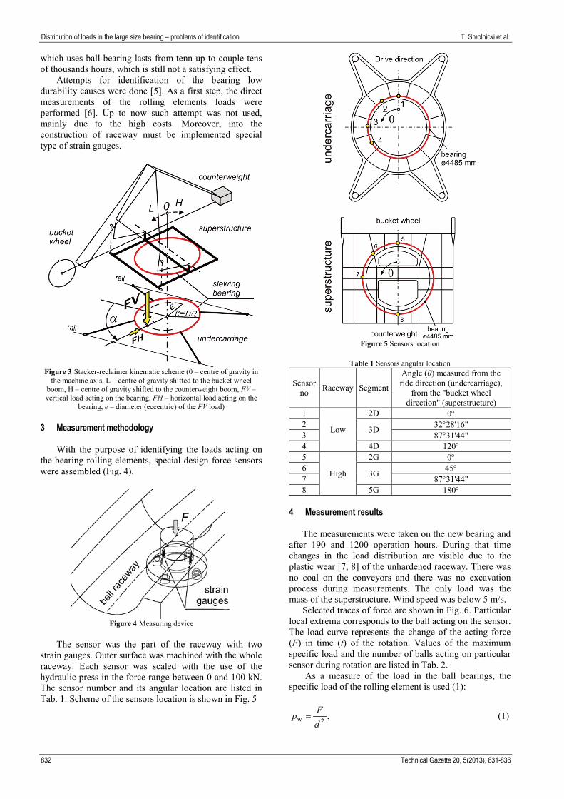
Figure 3 Stacker-reclaimer kinematic scheme (0 – centre of gravity in
the machine axis, L – centre of gravity shifted to the bucket wheel boom, H – centre of gravity shifted to the counterweight boom, FV – vertical load acting on the bearing, FH – horizontal load acting on the
bearing, e – diameter (eccentric) of the FV load) 3 Measurement methodology
With the purpose of identifying the loads acting on the bearing rolling elements, special design force sensors were assembled (Fig. 4).
Figure 4 Measuring device
The sensor was the part of the raceway with two
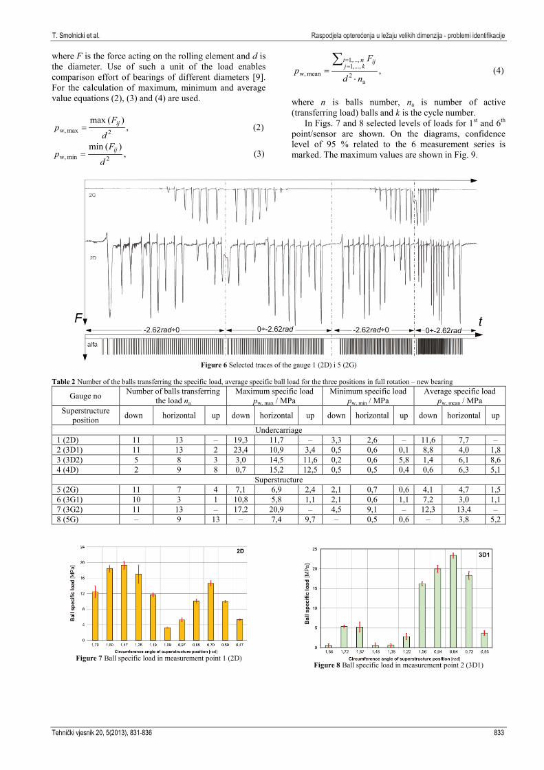
strain gauges. Outer surface was machined with the whole raceway. Each sensor was scaled with the use of the hydraulic press in the force range between 0 and 100 kN. The sensor number and its angular location are listed in Tab. 1. Scheme of the sensors location is shown in Fig. 5
Figure 5 Sensors location
Table 1 Sensors angular location
Sensor no Raceway Segment
Angle (θ) measured from the ride direction (undercarriage),
from the "bucket wheel direction" (superstructure)
1
Low
2D 0° 2 3D 32°28'16" 3 87°31'44" 4 4D 120° 5
High
2G 0° 6 3G 45° 7 87°31'44" 8 5G 180°
4 Measurement results
The measurements were taken on the new bearing and after 190 and 1200 operation hours. During that time changes in the load distribution are visible due to the plastic wear [7, 8] of the unhardened raceway. There was no coal on the conveyors and there was no excavation process during measurements. The only load was the mass of the superstructure. Wind speed was below 5 m/s.
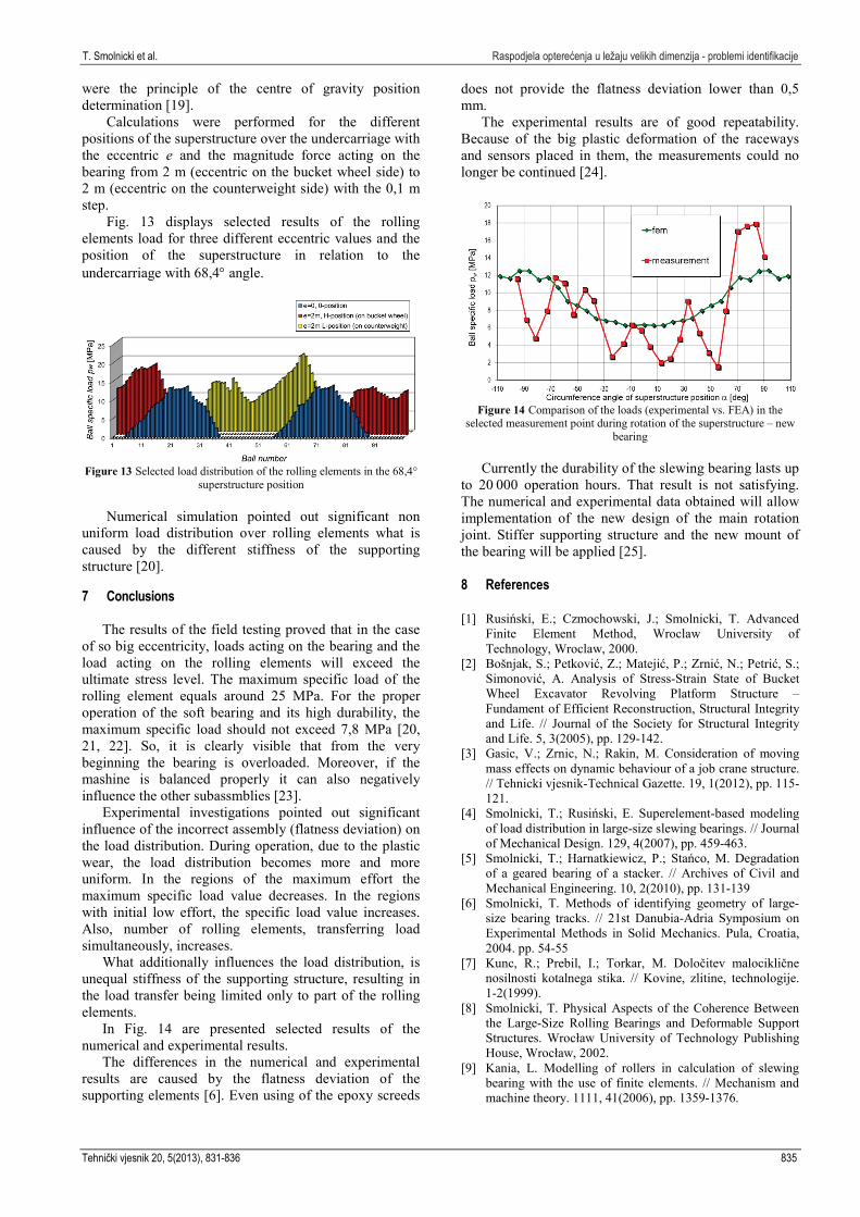
Selected traces of force are shown in Fig. 6. Particular local extrema corresponds to the ball acting on the sensor. The load curve represents the change of the acting force (F) in time (t) of the rotation. Values of the maximum specific load and the number of balls acting on particular sensor during rotation are listed in Tab. 2.
As a measure of the load in the ball bearings, the specific load of the rolling element is used (1):
,2w dFp = (1)
832 Technical Gazette 20, 5(2013), 831-836
T. Smolnicki et al. Raspodjela opterećenja u ležaju velikih dimenzija - problemi identifikacije
where F is the force acting on the rolling element and d is the diameter. Use of such a unit of the load enables comparison effort of bearings of different diameters [9]. For the calculation of maximum, minimum and average value equations (2), (3) and (4) are used.
,)(max
2max w, d
Fp ij= (2)
,)(min
2min w, d
Fp ij= (3)
,a
2 ,...,1 ,...,1
mean w, nd
Fp kj
ni ij
⋅=∑
==
(4)
where n is balls number, na is number of active (transferring load) balls and k is the cycle number.
In Figs. 7 and 8 selected levels of loads for 1st and 6th point/sensor are shown. On the diagrams, confidence level of 95 % related to the 6 measurement series is marked. The maximum values are shown in Fig. 9.
Figure 6 Selected traces of the gauge 1 (2D) i 5 (2G)
Table 2 Number of the balls transferring the specific load, average specific ball load for the three positions in full rotation – new bearing
Gauge no Number of balls transferring the load na
Maximum specific load pw, max / MPa
Minimum specific load pw, min / MPa
Average specific load pw, mean / MPa
Superstructure position down horizontal up down horizontal up down horizontal up down horizontal up
Undercarriage 1 (2D) 11 13 – 19,3 11,7 – 3,3 2,6 – 11,6 7,7 – 2 (3D1) 11 13 2 23,4 10,9 3,4 0,5 0,6 0,1 8,8 4,0 1,8 3 (3D2) 5 8 3 3,0 14,5 11,6 0,2 0,6 5,8 1,4 6,1 8,6 4 (4D) 2 9 8 0,7 15,2 12,5 0,5 0,5 0,4 0,6 6,3 5,1
Superstructure 5 (2G) 11 7 4 7,1 6,9 2,4 2,1 0,7 0,6 4,1 4,7 1,5 6 (3G1) 10 3 1 10,8 5,8 1,1 2,1 0,6 1,1 7,2 3,0 1,1 7 (3G2) 11 13 – 17,2 20,9 – 4,5 9,1 – 12,3 13,4 – 8 (5G) – 9 13 – 7,4 9,7 – 0,5 0,6 – 3,8 5,2
Figure 7 Ball specific load in measurement point 1 (2D)
Figure 8 Ball specific load in measurement point 2 (3D1)
Tehnički vjesnik 20, 5(2013), 831-836 833

Distribution of loads in the large size bearing – problems of identification T. Smolnicki et al.
Figure 9 Comparison of load in new bearing and after short operation
time bearing load
After 1200 hours of operation, loads acting on the ball in the stiff regions of the superstructure decreased. Loads acting on the ball in the lower stiffness areas of the superstructure increased.
5 Numerical model
Load distribution of the rolling elements was
determined. For that purpose, the numerical model of the superstructure platform, undercarriage portal frame and replacement model of the ball bearing was created [10, 11, 12] (Fig. 10). The model for the detailed simulations of the load distribution was separated from the global model of the structure (Fig. 11) in the places where kinematic pairs are present and it was loaded with the forces acting on those pairs.
Scheme of the replacements elements of the ball bearing is shown in Fig. 12. Bearing rings were modelled with the use of the beam elements (1), and every of the rolling elements with the replacements element which connects the middle of the curved upper and lower surface (2) [13, 14, 15, 16, 17, 8]. The bearing elements and the shell elements of the load carrying structure (4) were connected with the linear-elastic elements (3) with stiffness related to the stiffness of the bearing in the transverse direction.
Figure 10 Model of the system undercarriage portal frame – bearing –
superstructure platform
Characteristics displacement-force (F) of such an element is determined with numerical methods using the finite element volume models or the Hertz formulas. In that case, when the elements are under tensile load, the characteristic looks as follows (5):
,2
η
δ
⋅⋅⋅=
dEFdC (5)
where E is modulus of longitudinal elasticity, d is ball diameter and factor C and η equals 2,65 and 0,727 [8].
Figure 11 Stacker-reclaimer discrete model
Characteristic of the supporting row is clearance
value shifted. The numerical task is solved in the nonlinear physical and geometrical additive process with Newton-Rhapson iteration with stabilization [18].
Figure 12 Scheme of the replacement elements in the ball bearing
6 Results of FEA
Load of the bearing is reduced to the axial force FV
located on the eccentric e (Fig. 3). For the analysed bearing, value of the axial force equals 566 t. The value was obtained during experimental balancing of the stacker-reclaimer. The balancing procedure allowed also identification of the mass centre of the machine in cases of the up, down and horizontal position of the bucket wheel boom. Measurements of the stresses in the rails
834 Technical Gazette 20, 5(2013), 831-836
T. Smolnicki et al. Raspodjela opterećenja u ležaju velikih dimenzija - problemi identifikacije
were the principle of the centre of gravity position determination [19].
Calculations were performed for the different positions of the superstructure over the undercarriage with the eccentric e and the magnitude force acting on the bearing from 2 m (eccentric on the bucket wheel side) to 2 m (eccentric on the counterweight side) with the 0,1 m step.
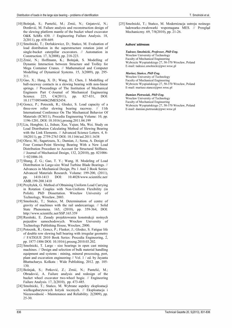
Fig. 13 displays selected results of the rolling elements load for three different eccentric values and the position of the superstructure in relation to the undercarriage with 68,4° angle.
Figure 13 Selected load distribution of the rolling elements in the 68,4°
superstructure position
Numerical simulation pointed out significant non uniform load distribution over rolling elements what is caused by the different stiffness of the supporting structure [20]. 7 Conclusions
The results of the field testing proved that in the case of so big eccentricity, loads acting on the bearing and the load acting on the rolling elements will exceed the ultimate stress level. The maximum specific load of the rolling element equals around 25 MPa. For the proper operation of the soft bearing and its high durability, the maximum specific load should not exceed 7,8 MPa [20, 21, 22]. So, it is clearly visible that from the very beginning the bearing is overloaded. Moreover, if the mashine is balanced properly it can also negatively influence the other subassmblies [23].
Experimental investigations pointed out significant influence of the incorrect assembly (flatness deviation) on the load distribution. During operation, due to the plastic wear, the load distribution becomes more and more uniform. In the regions of the maximum effort the maximum specific load value decreases. In the regions with initial low effort, the specific load value increases. Also, number of rolling elements, transferring load simultaneously, increases.
What additionally influences the load distribution, is unequal stiffness of the supporting structure, resulting in the load transfer being limited only to part of the rolling elements.
In Fig. 14 are presented selected results of the numerical and experimental results.
The differences in the numerical and experimental results are caused by the flatness deviation of the supporting elements [6]. Even using of the epoxy screeds
does not provide the flatness deviation lower than 0,5 mm.
The experimental results are of good repeatability. Because of the big plastic deformation of the raceways and sensors placed in them, the measurements could no longer be continued [24].
Figure 14 Comparison of the loads (experimental vs. FEA) in the
selected measurement point during rotation of the superstructure – new bearing
Currently the durability of the slewing bearing lasts up
to 20.000 operation hours. That result is not satisfying. The numerical and experimental data obtained will allow implementation of the new design of the main rotation joint. Stiffer supporting structure and the new mount of the bearing will be applied [25]. 8 References [1] Rusiński, E.; Czmochowski, J.; Smolnicki, T. Advanced
Finite Element Method, Wroclaw University of Technology, Wroclaw, 2000.
[2] Bošnjak, S.; Petković, Z.; Matejić, P.; Zrnić, N.; Petrić, S.; Simonović, A. Analysis of Stress-Strain State of Bucket Wheel Excavator Revolving Platform Structure – Fundament of Efficient Reconstruction, Structural Integrity and Life. // Journal of the Society for Structural Integrity and Life. 5, 3(2005), pp. 129-142.
[3] Gasic, V.; Zrnic, N.; Rakin, M. Consideration of moving mass effects on dynamic behaviour of a job crane structure. // Tehnicki vjesnik-Technical Gazette. 19, 1(2012), pp. 115-121.
[4] Smolnicki, T.; Rusiński, E. Superelement-based modeling of load distribution in large-size slewing bearings. // Journal of Mechanical Design. 129, 4(2007), pp. 459-463.
[5] Smolnicki, T.; Harnatkiewicz, P.; Stańco, M. Degradation of a geared bearing of a stacker. // Archives of Civil and Mechanical Engineering. 10, 2(2010), pp. 131-139
[6] Smolnicki, T. Methods of identifying geometry of large-size bearing tracks. // 21st Danubia-Adria Symposium on Experimental Methods in Solid Mechanics. Pula, Croatia, 2004. pp. 54-55
[7] Kunc, R.; Prebil, I.; Torkar, M. Določitev malociklične nosilnosti kotalnega stika. // Kovine, zlitine, technologije. 1-2(1999).
[8] Smolnicki, T. Physical Aspects of the Coherence Between the Large-Size Rolling Bearings and Deformable Support Structures. Wrocław University of Technology Publishing House, Wrocław, 2002.
[9] Kania, L. Modelling of rollers in calculation of slewing bearing with the use of finite elements. // Mechanism and machine theory. 1111, 41(2006), pp. 1359-1376.
Tehnički vjesnik 20, 5(2013), 831-836 835
Distribution of loads in the large size bearing – problems of identification T. Smolnicki et al.
[10] Bošnjak, S.; Pantelić, M.; Zrnić, N.; Gnjatović, N.; Đorđević, M. Failure analysis and reconstruction design of the slewing platform mantle of the bucket wheel excavator O&K SchRs 630. // Engineering Failure Analysis. 18, 2(2011), pp. 658-669.
[11] Smolnicki, T.; Derlukiewicz, D.; Stańco, M. Evaluation of load distribution in the superstructure rotation joint of single-bucket caterpillar excavators. // Automation in Construction. 17, 3(2008), pp. 218-223.
[12] Zrnić, N.; Hoffmann, K.; Bošnjak, S. Modelling of Dynamic Interaction between Structure and Trolley for Mega Container Cranes. // Mathematical and Computer Modelling of Dynamical Systems. 15, 3(2009), pp. 295-311.
[13] Gao, X.; Hang, X. D.; Wang, H.; Chen, J. Modelling of ball-raceway contacts in a slewing bearing with non-linear springs. // Proceedings of The Institution of Mechanical Engineers Part C-Journal of Mechanical Engineering Science. 225, C4(2011), pp. 827-831, DOI: 10.1177/09544062JMES2454.
[14] Goncz, P.; Potocnik, R.; Glodez, S. Load capacity of a three-row roller slewing bearing raceway. // 11th International Conference On The Mechanical Behavior Of Materials (ICM11), Procedia Engineering Volume: 10, pp. 1196-1201, DOI: 10.1016/j.proeng.2011.04.199
[15] Liu, Hongbin; Li, Jishun; Xue, Yujun; Ma, Wei. Study on Load Distribution Calculating Method of Slewing Bearing with the Link Elements. // Advanced Science Letters. 4, 8-10(2011), pp. 2759-2763 DOI: 10.1166/asl.2011.1638
[16] Olave, M.; Sagartzazu, X.; Damian, J.; Serna, A. Design of Four Contact-Point Slewing Bearing With a New Load Distribution Procedure to Account for Structural Stiffness. // Journal of Mechanical Design, 132, 2(2010), pp. 021006-1÷021006-10.
[17] Shang, Z. G.; Gao, T. Y.; Wang, H. Modeling of Load Distribution in Large-size Wind Turbine Blade Bearings. // Advances in Mechanical Design, Pts 1 And 2 Book Series: Advanced Materials Research. Volume: 199-200, (2011), pp. 1410-1413 DOI: 10.4028/www.scientific.net/ AMR.199-200.1410
[18] Przybyłek, G. Method of Obtaining Uniform Load Carrying in Rotation Couples with Non-Uniform Flexibility (in Polish). PhD Dissertation. Wrocław University of Technology, Wrocław, 2003.
[19] Smolnicki, T.; Stańco, M. Determination of centre of gravity of machines with the rail undercarriage. // Solid State Phenomena. 165, (2010), pp. 359-364, DOI: http://www.scientific.net/SSP.165.359
[20] Rusiński, E. Zasady projektowania konstrukcji nośnych pojazdów samochodowych. Wrocław University of Technology Publishing House, Wrocław, 2000.
[21] Potocnik, R.; Goncz, P.; Flasker, J.; Glodez, S. Fatigue life of double row slewing ball bearing with irregular geometry // FATIGUE 2010 Book Series: Procedia Engineering, 2, pp. 1877-1886 DOI: 10.1016/j.proeng.2010.03.202.
[22] Smolnicki, T. Large - size bearings in open cast mining machines. // Design and selection of bulk material handling equipment and systems : mining, mineral processing, port, plant and excavation engineering // Vol. 1 / ed. by Jayanta Bhattacharya. Kolkata : Wide Publishing, 2012. pp. 105-130.
[23] Bošnjak, S.; Petković, Z.; Zrnić, N.; Pantelić, M.; Obradović, A. Failure analysis and redesign of the bucket wheel excavator two-wheel bogie. // Engineering Failure Analysis. 17, 2(2010), pp. 473-485.
[24] Smolnicki, T.; Stańco, M. Wybrane aspekty eksploatacji wielkogabarytowych łożysk tocznych. // Eksploatacja i Niezawodność - Maintenance and Reliability. 2(2009), pp. 25-30.
[25] Smolnicki, T.; Stańco, M. Modernizacja ustroju nośnego ładowarko-zwałowarki wspomagana MES. // Przegląd Mechaniczny. 69, 7/8(2010), pp. 21-26.
Authors’ addresses Tadeusz Smolnicki, Professor, PhD Eng. Wrocław University of Technology Faculty of Mechanical Engineering Wybrzeże Wyspiańskiego 27, 50-370 Wrocław, Poland E-mail: [email protected] Mariusz Stańco, PhD Eng. Wrocław University of Technology Faculty of Mechanical Engineering Wybrzeże Wyspiańskiego 27, 50-370 Wrocław, Poland E-mail: [email protected] Damian Pietrusiak, PhD Eng. Wrocław University of Technology Faculty of Mechanical Engineering Wybrzeże Wyspiańskiego 27, 50-370 Wrocław, Poland E-mail: [email protected]
836 Technical Gazette 20, 5(2013), 831-836