Tutorial: System structure modeling using MagicDraw Vlad Acretoaie Technical University of Denmark Courses 02341, 02264

Welcome message from author
This document is posted to help you gain knowledge. Please leave a comment to let me know what you think about it! Share it to your friends and learn new things together.
Transcript

Tutorial: System structure modeling using
MagicDraw
Vlad Acretoaie Technical University of Denmark
Courses 02341, 02264

Abstract
Diagram UML Diagram Type
System Context Diagram Use Case Diagram
Domain Architecture Diagram Use Case Diagram
System Structure Diagram Composite Structure Diagram
This tutorial provides instructions for system structure modeling using MagicDraw in the context of DTU courses 02341 and 02264. The required UML diagrams and model elements are introduced based on the Library Management System example used in the lectures. The following diagrams are featured:
2
Note: Existing model elements must be re-used whenever possible (i.e. it is redundant and usually wrong to create two actors, components, etc., with the same name).

Project structure
3
Before starting work on a model, it is good practice to create a clear package structure that indicates where a particular diagram belongs. This helps separate the various abstraction levels of the system design such as its domain analysis, its static structure, its behavior, and its deployment information. Your project should have the same package structure as the Library Management System (LMS) case study used throughout the lectures. Considering the package structure of the LMS case study, the system structure models presented in this tutorial should be placed in a package called “System Parts”.

4
A new Package is added from the context menu of the containment hierarchy. Remember to also re-name the containment hierarchy root to your project name.
Project structure: Creating a package

Package Structure Creating a package
5
After adding the “System Parts” package, the containment hierarchy should look like the one below (but have your specific top-level package name instead of LMS).
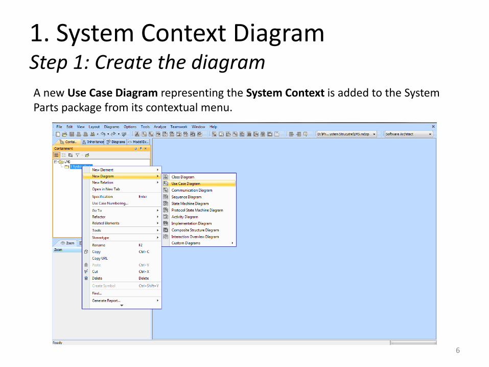
1. System Context Diagram Step 1: Create the diagram
6
A new Use Case Diagram representing the System Context is added to the System Parts package from its contextual menu.

1. System Context Diagram Step 1: Create the diagram
7
The created System Context diagram is highlighted in the project containment hierarchy in red below.

1. System Context Diagram Step 2: Add actors
8
Actors included in the system context are added to the diagram using the toolbar button highlighted in red below.

1. System Context Diagram Step 3: Add components
9
Components included in the system context are added to the diagram using the toolbar button highlighted in red below.

1. System Context Diagram Step 4: Add associations
10
Associations between actors and components are added to the diagram using the toolbar button highlighted in red on the next slide. Note: Actors and components are directly connected by associations. Ports are not required on the System Context diagram, since UML does not support connecting actors with ports on a Use Case diagram.

1. System Context Diagram Step 4: Add associations
11

2. Domain Architecture Diagram Step 1: Create the diagram
12
A new Use Case Diagram is representing the Domain Architecture is added to the System Parts package from its contextual menu.

2. Domain Architecture Diagram Step 1: Create the diagram
13
The created Domain Architecture diagram is highlighted in the project containment hierarchy in red below.

2. Domain Architecture Diagram Step 2: Add the system
14
The outermost domain (“the system”) is added to the diagram by dragging it from the containment tree – in this example it is the LMS component highlighted in red.
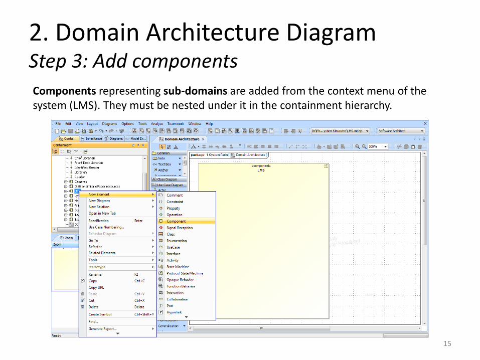
2. Domain Architecture Diagram Step 3: Add components
15
Components representing sub-domains are added from the context menu of the system (LMS). They must be nested under it in the containment hierarchy.

2. Domain Architecture Diagram Step 3: Add components
16
The sub-domains nested in the containment hierarchy under the outer domain are highlighted in red below.

2. Domain Architecture Diagram Step 4: Add use cases
17
Use cases are added from the context menu of the sub-domain which realizes them. They must be nested under this domain in the containment hierarchy.

2. Domain Architecture Diagram Step 4: Add use cases
18
The use cases nested in the containment hierarchy under the Media domain are highlighted in red below. They are also visible on the diagram.

3. System Structure Diagram Step 1: Create the diagram
19
A new Composite Structure Diagram representing the System Structure is added to the System Parts package from its contextual menu.

3. System Structure Diagram Step 1: Create the diagram
20
MagicDraw prompts for a name and context of the new diagram. The context must be specified as the system being modeled (in this example the LMS component).

3. System Structure Diagram Step 1: Create the diagram
21
The created System Structure diagram is highlighted in the project containment hierarchy in red below.

3. System Structure Diagram Step 2: Add system and subsystems
22
The system and sub-systems are dragged to the diagram from the containment hierarchy. They have already been created for the Domain Architecture diagram.

3. System Structure Diagram Step 3: Add actors
23
Actors that interact with the system are dragged to the diagram from the containment hierarchy. They have already been created for the System Context diagram. Notice the different concrete syntax (shape) that actors have in a Composite Structure diagram. Instead of stick figures they are now represented as rectangles, as shown by the Reader actor highlighted in red in the following screenshot.

3. System Structure Diagram Step 3: Add actors
24

3. System Structure Diagram Step 4: Add ports
25
Ports are added by clicking on a system in the diagram and selecting the port entry from the pop-up menu that appears on screen.

3. System Structure Diagram Step 4: Add ports
26
A dialog prompting for a port type will pop up. You may select <UNSPECIFIED> for the purpose of this diagram.

3. System Structure Diagram Step 4: Add ports
27
The created ports are visible on the diagram. The ports of the Media sub-system are highlighted in red in the containment tree.

3. System Structure Diagram Step 5: Name ports
28
Names are set for ports using the Specification entry in each port’s context menu.

3. System Structure Diagram Step 5: Name ports
29
The example diagram with all ports named is displayed below.

3. System Structure Diagram Step 6: Add connectors
30
Finally, Connectors are added between ports using the toolbar button highlighted in red below.
Related Documents