This is the author version published as: This is the accepted version of this article. To be published as : This is the author’s version published as: Catalogue from Homo Faber 2007 QUT Digital Repository: http://eprints.qut.edu.au/ Banks, Jasmine Elizabeth (2011) The Spartan3E Tutorial 1 : Introduction to FPGA Programming, Version 1.0. [Tutorial Programme] Copyright 2011 Queensland University of Technology

Welcome message from author
This document is posted to help you gain knowledge. Please leave a comment to let me know what you think about it! Share it to your friends and learn new things together.
Transcript

This is the author version published as: This is the accepted version of this article. To be published as : This is the author’s version published as: Catalogue from Homo Faber 2007
QUT Digital Repository: http://eprints.qut.edu.au/
Banks, Jasmine Elizabeth (2011) The Spartan3E Tutorial 1 : Introduction to FPGA Programming, Version 1.0. [Tutorial Programme]
Copyright 2011 Queensland University of Technology

Tutorial 1: Introduction to FPGA Programming 1
Xilinx Spartan-3E Project Navigator Version 12.4
The Spartan-3E Tutorial 1:
Introduction to FPGA Programming
Version 1.0
Author: Jasmine Banks
© 2011, Queensland University of Technology

Tutorial 1: Introduction to FPGA Programming 2
Xilinx Spartan-3E Project Navigator Version 12.4

Tutorial 1: Introduction to FPGA Programming 3
Xilinx Spartan-3E Project Navigator Version 12.4
Acknowledgements
Parts of this tutorial are based on an earlier version written for Project Navigator version 9.2, written by Michael Bakker, Matthew Grace and Warwick Kilroy, as part of ENB345 – Advanced Design in 2008.

Tutorial 1: Introduction to FPGA Programming 4
Xilinx Spartan-3E Project Navigator Version 12.4

Tutorial 1: Introduction to FPGA Programming 5
Xilinx Spartan-3E Project Navigator Version 12.4
Glossary
VHDL
VHSIC
VHSIC Hardware Description Language
Very High Speed Integrated Circuit

Tutorial 1: Introduction to FPGA Programming 6
Xilinx Spartan-3E Project Navigator Version 12.4

Tutorial 1: Introduction to FPGA Programming 7
Xilinx Spartan-3E Project Navigator Version 12.4
Table of Contents
Acknowledgements ……………………………………………………….......……………….
Glossary ……………………………………………………………………….......…………..
1.0 Introduction ………………………………………………………………....…….………
1.1 Design Functionality ………………………………………………………..………...
1.2 Relevant Documentation ..…………………………….……………………..………..
1.3 Scope ………………………………………………………………………....……….
2.0 Equipment …………………………………………………………………......………….
3.0 Procedure …………………………………………………………………........…………
3.1 Startup …………………………………………………………………...……………
3.2 Additional Help …………………………………………………………....………….
3.3 Creating a New Project ……………………………………………………....……….
3.4 Adding a New VHDL Source ……………………………………………..……….…
3.5 Editing the VHDL Source ………………………………………………....………….
3.6 Syntax Checking …………………………………………………………....………...
3.7 Pin Assignment …………………………………………………………....………….
3.8 Synthesize, Translate, Map and Place & Route ……........………………....…………
3.9 Download Design to Board …………………………………………………...………
3.10 Running the Program on the Spartan-3E Board …………………………....………..
4.0 Further Information ……………………………………………………….....……………
5.0 References ………………………………………………………………...………………
page
3
5
13
13
13
13
14
16
16
16
17
20
25
27
29
33
35
48
49
51

Tutorial 1: Introduction to FPGA Programming 8
Xilinx Spartan-3E Project Navigator Version 12.4

Tutorial 1: Introduction to FPGA Programming 9
Xilinx Spartan-3E Project Navigator Version 12.4
List of Figures
Figure 1: Project Navigator 12.4 initial startup window ……………………….......................
Figure 2: Spartan-3E Development Board ……………………………………........................
Figure 3: Help Menu ……………………………………………………………….…………
Figure 4: New Project Wizard, Create New Project Page ……………………….……………
Figure 5: New Project Wizard, Project Settings Page ………………………………...………
Figure 6: New Project Wizard, Project Summary Page .….…….…………………………….
Figure 7: Adding a new source file to the project ……………...………..……………………
Figure 8: New Source Wizard, Select Source Type …………………………………..………
Figure 9: New Source Wizard, Define Module ……………………………………...………..
Figure 10: New Source Wizard, Summary ……………………………………………………
Figure 11: New source file top_level.vhd is now displayed in a tab ……………………….…
Figure 12: top_level.vhd, as displayed in Project Navigator, before editing ………………....
Figure 13: top_level.vhd, as displayed in Project Navigator, after editing …………………...
Figure 14: Portion of Project Navigator screen with Synthesize – XST expanded …...……...
Figure 15: A green tick next to Check Syntax shows that no errors were found …………….
Figure 16: A red cross next to Check Syntax indicates that an error was found ……………...
Figure 17: Portion of Project Navigator screen, with User Constraints expanded ……………
Figure 18: Dialog Box asking if you wish to create a UCF File …………………….………..
Figure 19: Initial appearance of PlanAhead window …………………………………………
Figure 20: I/O Ports displayed in a separate window …………………………………………
Figure 21: I/O Ports window with individual ports expanded ……………………………..…
Figure 22: I/O Ports window with values filled in ....................................................................
Figure 23: Portion of Project Navigator screen, with Implement Design expanded ………….
Figure 24: Portion of Project Navigator screen, with Implement Design expanded, after Translate, Map and Place & Route have successfully been run……………...
Page
14
15
16
17
18
19
20
21
22
23
24
25
26
27
28
28
30
30
31
31
32
32
33
34
Tutorial 1: Introduction to FPGA Programming 10
Xilinx Spartan-3E Project Navigator Version 12.4
Figure 25: Portion of Project Navigator screen, with Implement Design expanded .....………
Figure 26: Portion of Project Navigator screen, after Generate Programming File has successfully been run .…………………………………………….…....…….
Figure 27: The initial iMPACT window ……………………………………………...………
Figure 28: iMPACT window, after double-clicking on Boundary Scan …….……...….…….
Figure 29: iMPACT window, showing Initialize Chain selected ……………....…………….
Figure 30: iMPACT window, assign configuration files …………………………….……….
Figure 31: iMPACT window, assigning the configuration file for the xc3e500e …….....……
Figure 32: iMPACT window, dialog box asking if we wish to attach an SPI or BPI PROM ….
Figure 33: iMPACT window, bypassing the xcf04s …………………………………....…….
Figure 34: iMPACT window, bypassing the xc2c64a ……………………………....………..
Figure 35: iMPACT window, Device Programming Properties dialog box ……...…………..
Figure 36: iMPACT window, showing the device chain ……………………….…………….
Figure 37: iMPACT window, options which appear when right clicking on the xc3s500e ……
Figure 38: iMPACT window, after the program has been successfully downloaded to the Spartan-3E board ……………………………………………………...……..
Figure 39: The Spartan-3E board with the program running …………………...…………….
35
36
37
38
39
40
41
42
43
44
45
46
46
47
48

Tutorial 1: Introduction to FPGA Programming 11
Xilinx Spartan-3E Project Navigator Version 12.4
List of Tables
Table 1: Functionality implemented by this tutorial .…………………………………….……
Table 2: Input/output ports of the top_level entity ……………………………….…………...
Table 3: Values to enter in the I/O Ports window………………………………………….......
Page
13
29
32

Tutorial 1: Introduction to FPGA Programming 12
Xilinx Spartan-3E Project Navigator Version 12.4
Tutorial 1: Introduction to FPGA Programming 13
Xilinx Spartan-3E Project Navigator Version 12.4
1.0 Introduction
This tutorial is designed to help new users become familiar with using the Spartan-3E board. The tutorial steps through the following:
• Writing a small program in VHDL which carries out simple combinational logic. • Connecting the program inputs and outputs to the switches, buttons and LEDs on the Spartan-
3E board. • Downloading the program to the Spartan-3E board using the Project Navigator software.
1.1 Design Functionality
The functionality that is implemented by this tutorial is summarised in Table 1. Essentially, four of the LEDs on the board are lit depending on various combinations of slider switches and push buttons that are on.
LED0 ON when SW0 OR SW1 LED1 ON when SW2 OR SW3 LED2 ON when ( SW0 OR SW1 ) AND ( SW2 OR SW3 ) LED3 ON when Push Button 1 OR Push Button 2
Table 1: Functionality implemented by this tutorial.
1.2 Relevant Documentation
Before commencing the tutorial, it would be helpful to download the Spartan-3E FPGA Starter Kit Board User Guide [1]. This describes the pins of the FPGA chip and the settings required to connect them to the various input/output devices on the Spartan-3E board.
1.3 Scope
This tutorial is designed to help the user who is just starting to “get into” the Spartan-3E, by stepping through the process of creating a simple design and getting it running on the board. It is not designed to be a tutorial on VHDL – for help with VHDL syntax, the user can consult with a number of textbooks on the subject, such as [2,3], or find help online.
Tutorial 1: Introduction to FPGA Programming 14
Xilinx Spartan-3E Project Navigator Version 12.4
2.0 Equipment
The following are required to for working through this tutorial:
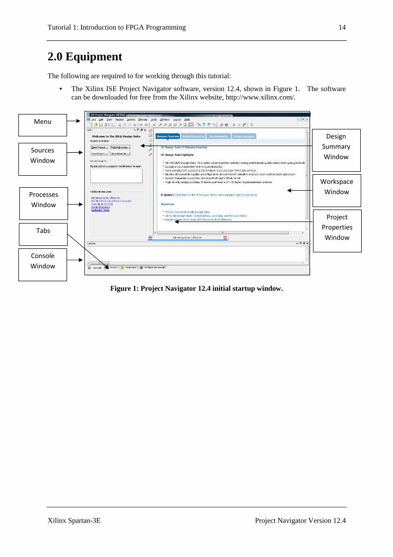
• The Xilinx ISE Project Navigator software, version 12.4, shown in Figure 1. The software can be downloaded for free from the Xilinx website, http://www.xilinx.com/.
Figure 1: Project Navigator 12.4 initial startup window.
Console
Window
Processes
Window
Sources
Window
Menu
Tabs
Workspace
Window
Design
Summary
Window
Project
Properties
Window

Tutorial 1: Introduction to FPGA Programming 15
Xilinx Spartan-3E Project Navigator Version 12.4
• The Spartan 3 Start-up Kit, including the Spartan-3E Development Board, Power Cable,
JTAG cable and USB cable for PC connection. The Spartan-3E Development board is shown in Figure 2.
Figure 2: Spartan-3E Development Board.
Reset
Button
ON/OFF
FPGA
JTAG
LEDs
SW0-3
Push
Buttons
LCD
USB
Power
Tutorial 1: Introduction to FPGA Programming 16
Xilinx Spartan-3E Project Navigator Version 12.4
3.0 Procedure
3.1 Startup
Start the Project Navigator software by going through the following directory by selecting:
Start→→→→All Programs→→→→Xilinx ISE Design Suite 12.4→→→→ISE Design Tools→→→→Project Navigator
3.2 Additional Help
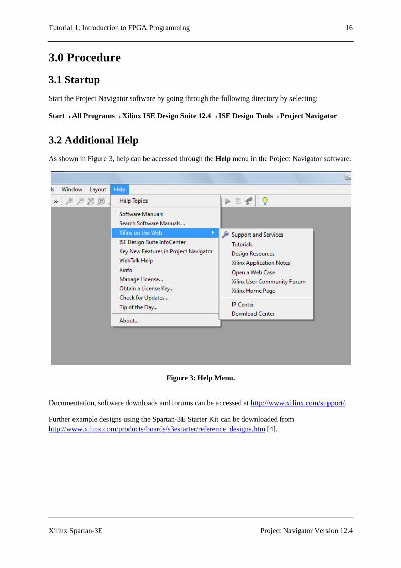
As shown in Figure 3, help can be accessed through the Help menu in the Project Navigator software.
Figure 3: Help Menu.
Documentation, software downloads and forums can be accessed at http://www.xilinx.com/support/.
Further example designs using the Spartan-3E Starter Kit can be downloaded from http://www.xilinx.com/products/boards/s3estarter/reference_designs.htm [4].
Tutorial 1: Introduction to FPGA Programming 17
Xilinx Spartan-3E Project Navigator Version 12.4
3.3 Creating a New Project
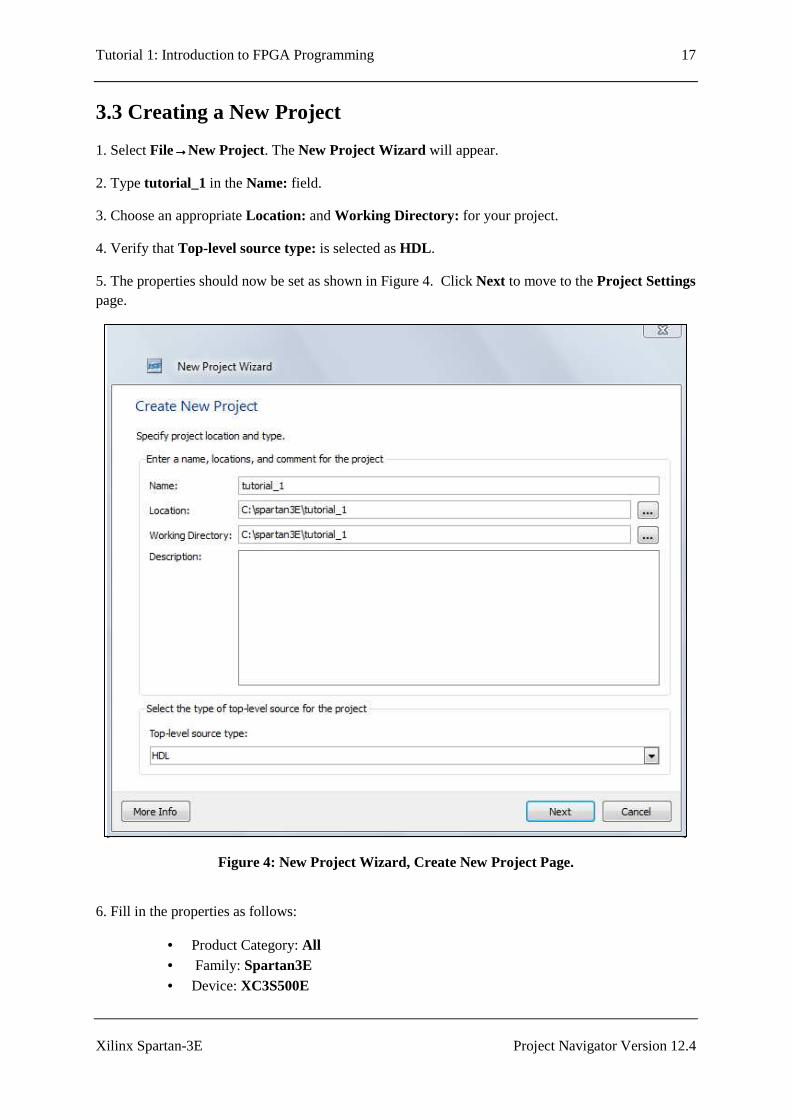
1. Select File→→→→New Project. The New Project Wizard will appear.
2. Type tutorial_1 in the Name: field.
3. Choose an appropriate Location: and Working Directory: for your project.
4. Verify that Top-level source type: is selected as HDL .
5. The properties should now be set as shown in Figure 4. Click Next to move to the Project Settings page.
Figure 4: New Project Wizard, Create New Project Page.
6. Fill in the properties as follows:
• Product Category: All • Family: Spartan3E • Device: XC3S500E
Tutorial 1: Introduction to FPGA Programming 18
Xilinx Spartan-3E Project Navigator Version 12.4
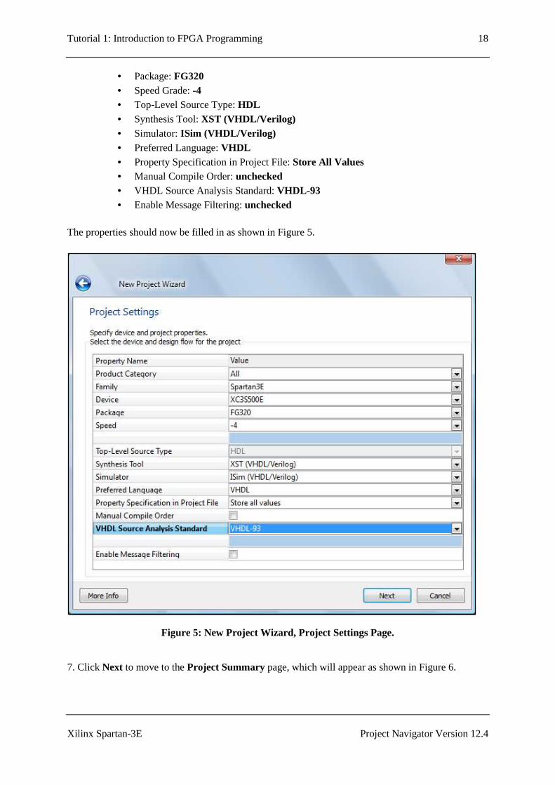
• Package: FG320 • Speed Grade: -4 • Top-Level Source Type: HDL • Synthesis Tool: XST (VHDL/Verilog) • Simulator: ISim (VHDL/Verilog) • Preferred Language: VHDL • Property Specification in Project File: Store All Values • Manual Compile Order: unchecked • VHDL Source Analysis Standard: VHDL-93 • Enable Message Filtering: unchecked
The properties should now be filled in as shown in Figure 5.
Figure 5: New Project Wizard, Project Settings Page.
7. Click Next to move to the Project Summary page, which will appear as shown in Figure 6.
Tutorial 1: Introduction to FPGA Programming 19
Xilinx Spartan-3E Project Navigator Version 12.4
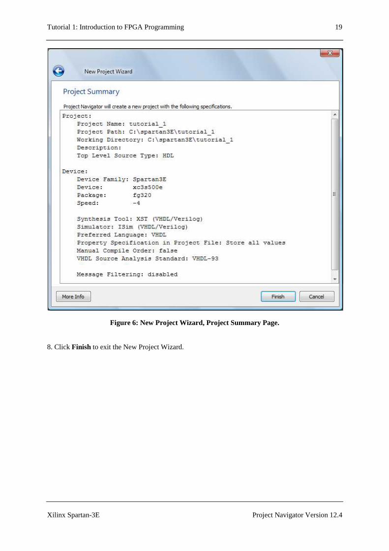
Figure 6: New Project Wizard, Project Summary Page.
8. Click Finish to exit the New Project Wizard.
Tutorial 1: Introduction to FPGA Programming 20
Xilinx Spartan-3E Project Navigator Version 12.4
3.4 Adding a New VHDL Source
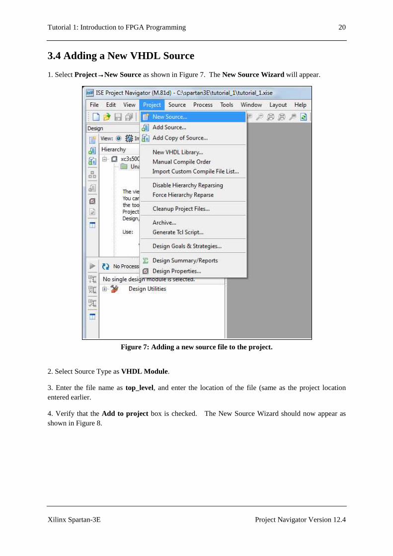
1. Select Project→→→→New Source as shown in Figure 7. The New Source Wizard will appear.
Figure 7: Adding a new source file to the project.
2. Select Source Type as VHDL Module .
3. Enter the file name as top_level, and enter the location of the file (same as the project location entered earlier.
4. Verify that the Add to project box is checked. The New Source Wizard should now appear as shown in Figure 8.

Tutorial 1: Introduction to FPGA Programming 21
Xilinx Spartan-3E Project Navigator Version 12.4
Figure 8: New Source Wizard, Select Source Type.
5. Click Next to go to the Define Module window.
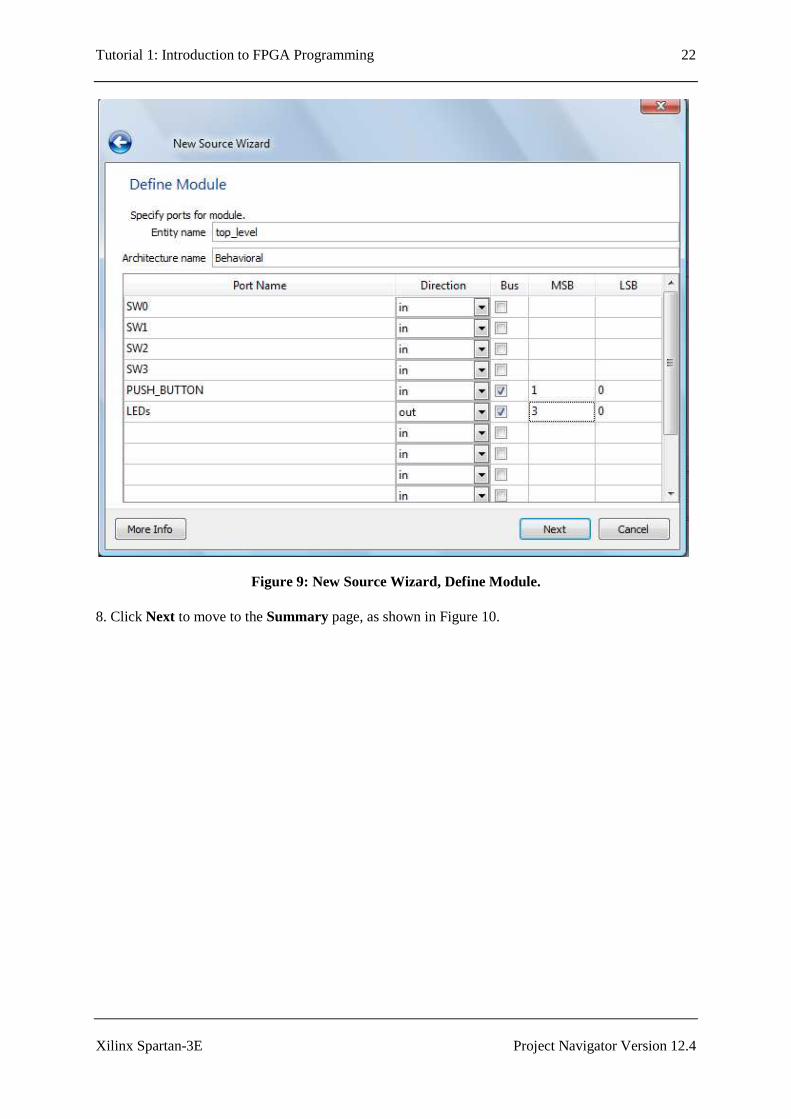
6. Define the ports (inputs and outputs of the design) by entering the information as shown in Figure 8. These ports are described as follows:
• SW0-3 will be single bit inputs, and will be connected with the slide switches on the Spartan-3E.
• PUSH_BUTTON will be an input consisting of two bits, and be connected with two of the push button switches on the Spartan 3E. Since this is a multiple bit input, make sure that the Bus check box is checked, MSB (most significant bit) is set to 1, and LSB (least significant bit) is set to 0.
• LEDs will be an output consisting of four bits, and will be connected with four of the LEDs on the Spartan-3E. Since this is a multiple bit output, make sure that the Bus check box is checked, MSB is set to 3, and LSB is set to 0.
7. The Define Module window will now appear as shown in Figure 9.
Tutorial 1: Introduction to FPGA Programming 22
Xilinx Spartan-3E Project Navigator Version 12.4
Figure 9: New Source Wizard, Define Module.
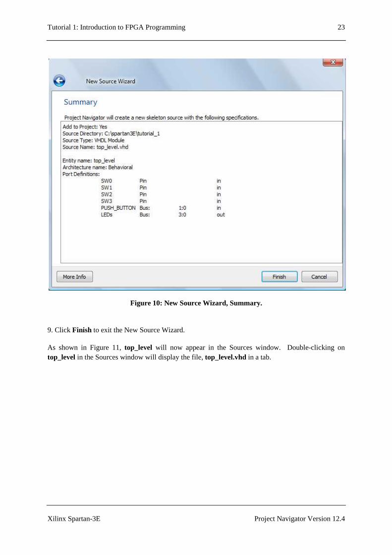
8. Click Next to move to the Summary page, as shown in Figure 10.
Tutorial 1: Introduction to FPGA Programming 23
Xilinx Spartan-3E Project Navigator Version 12.4
Figure 10: New Source Wizard, Summary.
9. Click Finish to exit the New Source Wizard.
As shown in Figure 11, top_level will now appear in the Sources window. Double-clicking on top_level in the Sources window will display the file, top_level.vhd in a tab.

Tutorial 1: Introduction to FPGA Programming 24
Xilinx Spartan-3E Project Navigator Version 12.4
Figure 11: New source file top_level.vhd is now displayed in a tab.
top_level in
Sources window Source code for
top_level.vhd
appears in this tab
Tutorial 1: Introduction to FPGA Programming 25
Xilinx Spartan-3E Project Navigator Version 12.4
3.5 Editing the VHDL Source
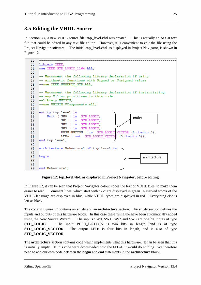
In Section 3.4, a new VHDL source file, top_level.vhd was created. This is actually an ASCII text file that could be edited in any text file editor. However, it is convenient to edit the file using the Project Navigator software. The initial top_level.vhd, as displayed in Project Navigator, is shown in Figure 12.
Figure 12: top_level.vhd, as displayed in Project Navigator, before editing.
In Figure 12, it can be seen that Project Navigator colour codes the text of VDHL files, to make them easier to read. Comment lines, which start with “- -” are displayed in green. Reserved words of the VHDL language are displayed in blue, while VHDL types are displayed in red. Everything else is left as black.
The code in Figure 12 contains an entity and an architecture section. The entity section defines the inputs and outputs of this hardware block. In this case these using the have been automatically added using the New Source Wizard. The inputs SW0, SW1, SW2 and SW3 are one bit inputs of type STD_LOGIC . The input PUSH_BUTTON is two bits in length, and is of type STD_LOGIC_VECTOR . The output LEDs is four bits in length, and is also of type STD_LOGIC_VECTOR .
The architecture section contains code which implements what this hardware. It can be seen that this is initially empty. If this code were downloaded onto the FPGA, it would do nothing. We therefore need to add our own code between the begin and end statements in the architecture block.
entity
architecture
Tutorial 1: Introduction to FPGA Programming 26
Xilinx Spartan-3E Project Navigator Version 12.4
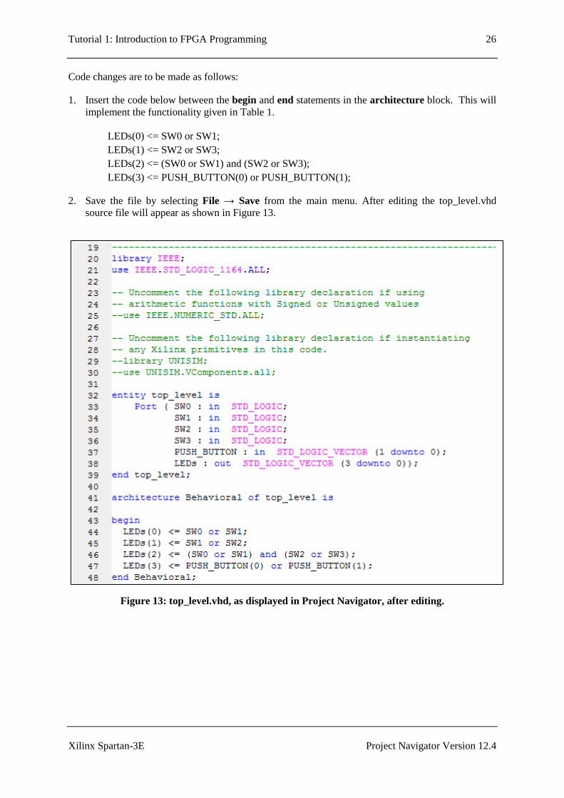
Code changes are to be made as follows:
1. Insert the code below between the begin and end statements in the architecture block. This will implement the functionality given in Table 1.
LEDs(0) <= SW0 or SW1; LEDs(1) <= SW2 or SW3; LEDs(2) <= (SW0 or SW1) and (SW2 or SW3); LEDs(3) <= PUSH_BUTTON(0) or PUSH_BUTTON(1);
2. Save the file by selecting File → Save from the main menu. After editing the top_level.vhd source file will appear as shown in Figure 13.
Figure 13: top_level.vhd, as displayed in Project Navigator, after editing.

Tutorial 1: Introduction to FPGA Programming 27
Xilinx Spartan-3E Project Navigator Version 12.4
3.6 Syntax Checking
The next step is to do syntax checking, to check that the VHDL code has been entered correctly. The following steps refer to the Project Navigator screen of Figure 14.
1. Verify that the Implementation check box toward the top left of the screen has been selected.
2. Verify that the Design tab has been selected.
3. Click on the ‘+’ next to Synthesize – XST. This will expand out to show various items, including Check Syntax.
Figure 14: Portion of Project Navigator screen with Synthesize – XST expanded.
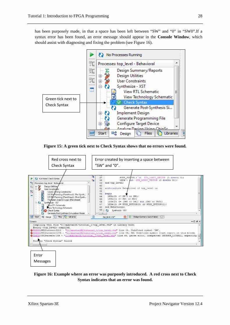
4. Double-click on Check Syntax. After some time, a green tick should appear beside Check Syntax, as shown in Figure 15. If instead, a red cross appears, this means a syntax error has been found. Any errors should be fixed before proceeding. For example, in Figure 16, a syntax error
Design tab
Synthesize - XST
Check Syntax
Implementation
Tutorial 1: Introduction to FPGA Programming 28
Xilinx Spartan-3E Project Navigator Version 12.4
has been purposely made, in that a space has been left between “SW” and “0” in “SW0”.If a syntax error has been found, an error message should appear in the Console Window, which should assist with diagnosing and fixing the problem (see Figure 16).
Figure 15: A green tick next to Check Syntax shows that no errors were found.
Figure 16: Example where an error was purposely introduced. A red cross next to Check Syntax indicates that an error was found.
Error
Messages
Red cross next to
Check Syntax
Error created by inserting a space between
“SW” and “0”.
Green tick next to
Check Syntax

Tutorial 1: Introduction to FPGA Programming 29
Xilinx Spartan-3E Project Navigator Version 12.4
3.7 Pin Assignment
Recall that the VHDL code for the top_level entity is:
We wish to connect the inputs and outputs of the top_level entity to the switches, buttons and LEDs on the Spartan-3E board. For example, we wish to get inputs SW0, SW1, SW2 and SW3 from the four slider switches. These are connected to pins L13, L14, H18 and N17 of the FPGA chip. Similarly, we wish to get inputs PUSH_BUTTON(0) and PUSH_BUTTON(1) from two of the push buttons on the board. In this case, we will use the North and East buttons, which are connected to pins V4 and H13 of the FPGA. Finally, we wish to connect the outputs LEDs(0), LEDs(1), LEDs(2) and LEDs(3) to four of the LEDs on the board. In this case we will use the four right-most LEDs, corresponding to pins F12, E12, E11 and F11 respectively.
For each input and output port of the top_level entity, Table 1 lists the name of the device on the Spartan-3E board that we wish to connect the port to, a description of what it physically corresponds to (slider switch, push button or LED), and the FPGA pin number that it is connected to. This information comes from the Spartan-3E FPGA Starter Kit Board User Guide [1].
Port name Spartan-3E board device name Description FPGA pin SW0 SW0 Slider switch L13 SW1 SW1 Slider switch L14 SW2 SW2 Slider switch H18 SW3 SW3 Slider switch N17 PUSH_BUTTON(0) BTN_North Push button V4 PUSH_BUTTON(1) BTN_East Push button H13 LEDs(0) LD0 LED F12 LEDs(1) LD1 LED E12 LEDs(2) LD2 LED E11 LEDs(3) LD3 LED F11
Table 2: Input/output ports of the top_level entity; and the name, description and FPGA pin no. of the devices on the Spartan-3E board that the ports will be connected to.
The following steps are used to connect the inputs and outputs to the switches, buttons and LEDs on the Spartan-3E board:
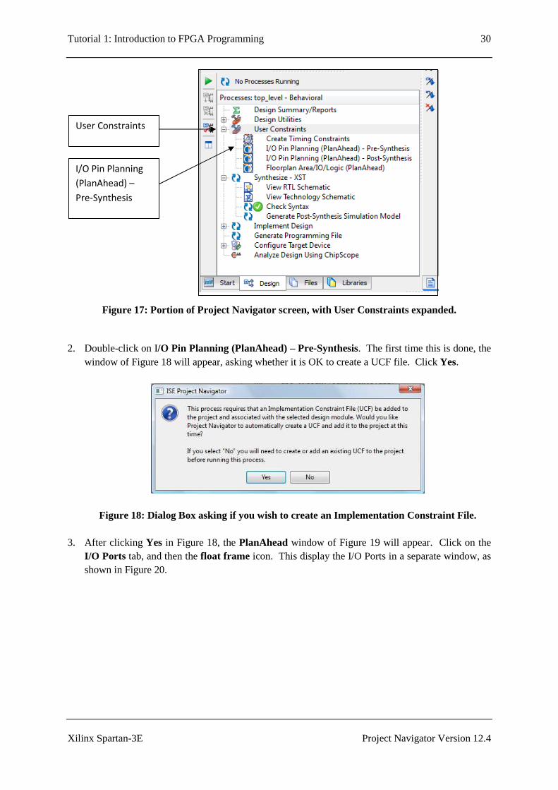
1. As shown in Figure 17, click on the ‘+’ next to User Constraints. This will expand out to show various items, including I/O Pin Planning (PlanAhead) – Pre-Synthesis.
entity top_level is Port ( SW0 : in STD_LOGIC; SW1 : in STD_LOGIC; SW2 : in STD_LOGIC; SW3 : in STD_LOGIC; PUSH_BUTTON : in STD_LOGIC_VECTOR (1 downto 0); LEDs : out STD_LOGIC_VECTOR (3 downto 0)); end top_level;
Tutorial 1: Introduction to FPGA Programming 30
Xilinx Spartan-3E Project Navigator Version 12.4
Figure 17: Portion of Project Navigator screen, with User Constraints expanded.
2. Double-click on I/O Pin Planning (PlanAhead) – Pre-Synthesis. The first time this is done, the
window of Figure 18 will appear, asking whether it is OK to create a UCF file. Click Yes.
Figure 18: Dialog Box asking if you wish to create an Implementation Constraint File.
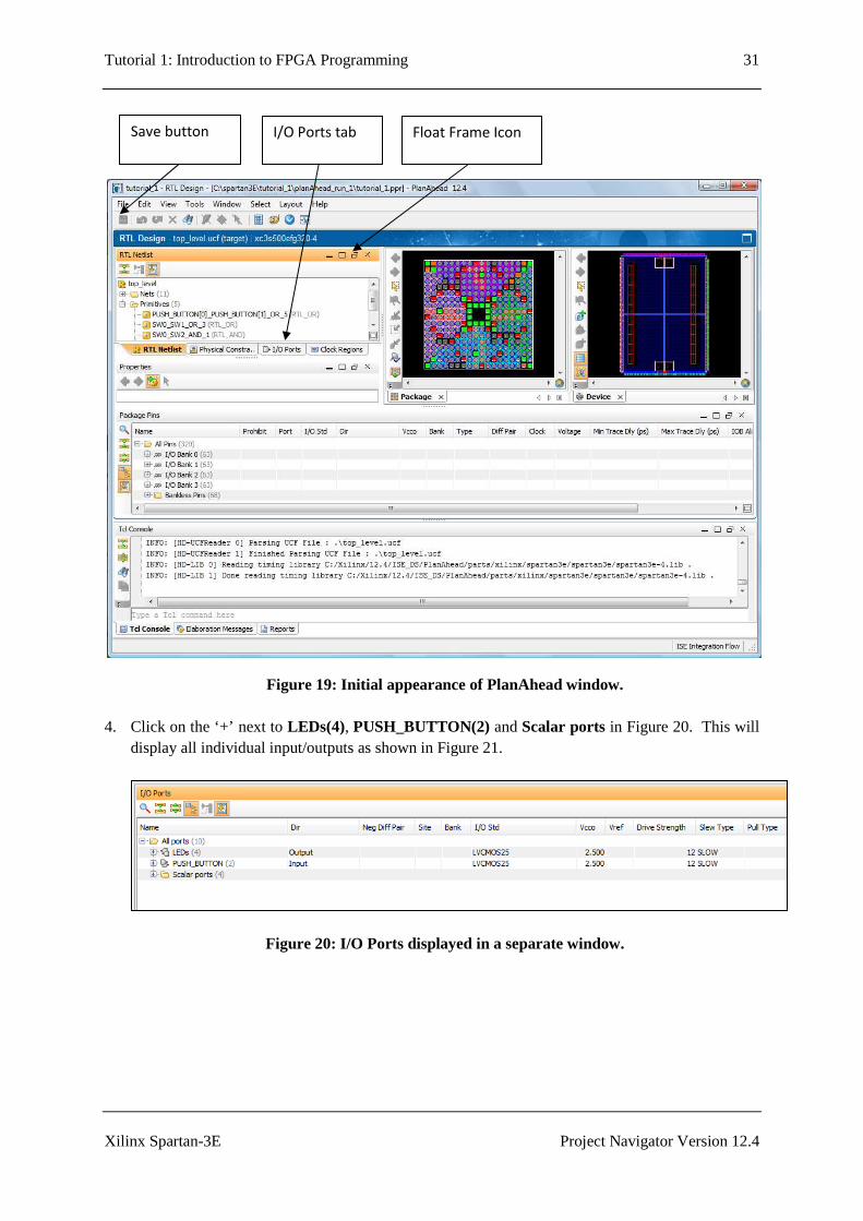
3. After clicking Yes in Figure 18, the PlanAhead window of Figure 19 will appear. Click on the I/O Ports tab, and then the float frame icon. This display the I/O Ports in a separate window, as shown in Figure 20.
User Constraints
I/O Pin Planning
(PlanAhead) –
Pre-Synthesis
Tutorial 1: Introduction to FPGA Programming 31
Xilinx Spartan-3E Project Navigator Version 12.4
Figure 19: Initial appearance of PlanAhead window.
4. Click on the ‘+’ next to LEDs(4), PUSH_BUTTON(2) and Scalar ports in Figure 20. This will display all individual input/outputs as shown in Figure 21.
Figure 20: I/O Ports displayed in a separate window.
I/O Ports tab Float Frame Icon Save button
Tutorial 1: Introduction to FPGA Programming 32
Xilinx Spartan-3E Project Navigator Version 12.4
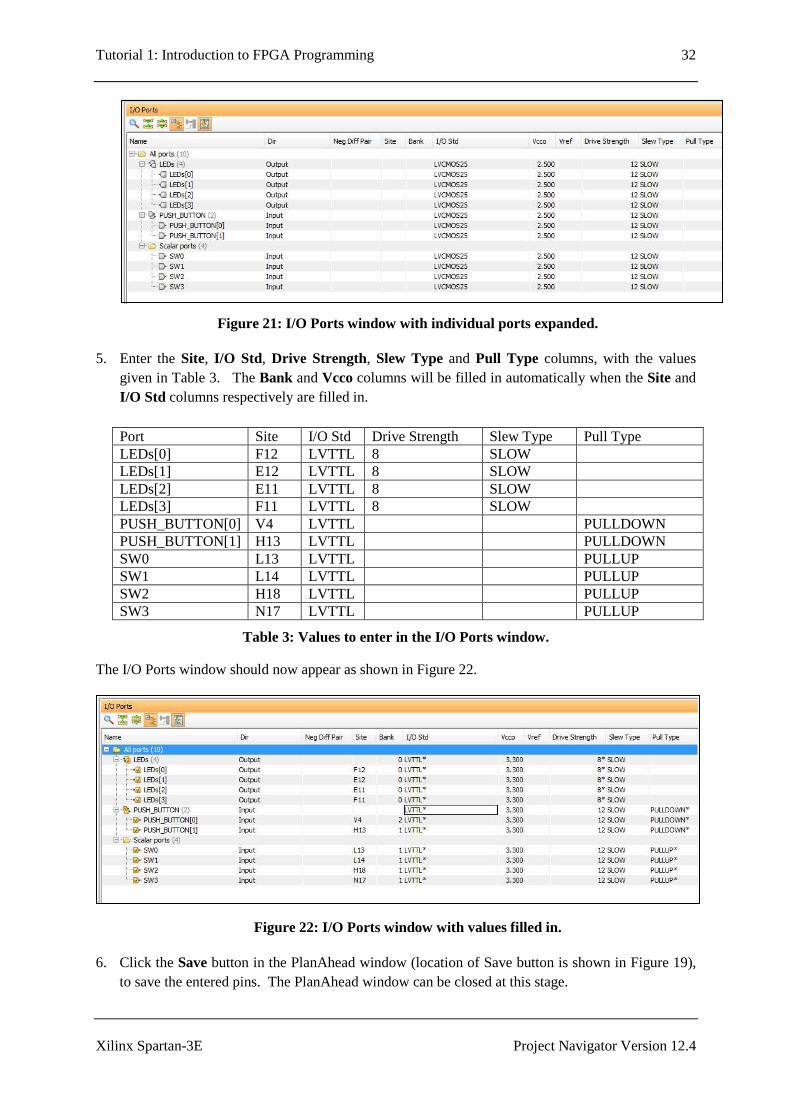
Figure 21: I/O Ports window with individual ports expanded.
5. Enter the Site, I/O Std, Drive Strength, Slew Type and Pull Type columns, with the values given in Table 3. The Bank and Vcco columns will be filled in automatically when the Site and I/O Std columns respectively are filled in. Port Site I/O Std Drive Strength Slew Type Pull Type LEDs[0] F12 LVTTL 8 SLOW LEDs[1] E12 LVTTL 8 SLOW LEDs[2] E11 LVTTL 8 SLOW LEDs[3] F11 LVTTL 8 SLOW PUSH_BUTTON[0] V4 LVTTL PULLDOWN PUSH_BUTTON[1] H13 LVTTL PULLDOWN SW0 L13 LVTTL PULLUP SW1 L14 LVTTL PULLUP SW2 H18 LVTTL PULLUP SW3 N17 LVTTL PULLUP
Table 3: Values to enter in the I/O Ports window.
The I/O Ports window should now appear as shown in Figure 22.
Figure 22: I/O Ports window with values filled in.
6. Click the Save button in the PlanAhead window (location of Save button is shown in Figure 19), to save the entered pins. The PlanAhead window can be closed at this stage.

Tutorial 1: Introduction to FPGA Programming 33
Xilinx Spartan-3E Project Navigator Version 12.4
3.8 Synthesize, Translate, Map, and Place & Route
The next stage involves going through the Synthesize, Translate, Map and Place and Route Steps. These steps are carried out by the Project Navigator software, and are briefly described as follows:
• Synthesize: generates netlists for each source file. • Translate: merges multiple files into a single netlist. • Map: the design is mapped to slices and I/O blocks. • Place and Route: works out how the design is to be placed on the chip and components
connected.
1. As shown in Figure 23, click on the ‘+’ next to Implement Design. This will expand out to show the Translate, Map and Place & Route stages.
Figure 23: Portion of Project Navigator screen, with Implement Design expanded.
2. Double-click on Implement Design. This will first cause Synthesize – XST to run. Next,
Translate, Map and Place & Route will run in turn. As each stage is completed, a green tick will appear next to it. After all three stages are complete, the Project Navigator screen will appear as shown in Figure 24.
Synthesize - XST
Implement
Design

Tutorial 1: Introduction to FPGA Programming 34
Xilinx Spartan-3E Project Navigator Version 12.4
Figure 24: Portion of Project Navigator screen, with Implement Design expanded, after Translate, Map and Place & Route have successfully been run.
Tutorial 1: Introduction to FPGA Programming 35
Xilinx Spartan-3E Project Navigator Version 12.4
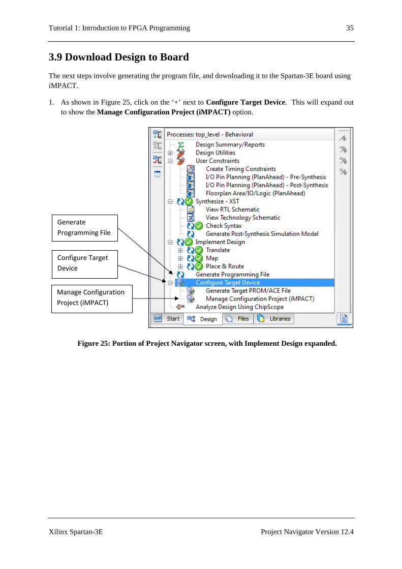
3.9 Download Design to Board
The next steps involve generating the program file, and downloading it to the Spartan-3E board using iMPACT.
1. As shown in Figure 25, click on the ‘+’ next to Configure Target Device. This will expand out to show the Manage Configuration Project (iMPACT) option.
Figure 25: Portion of Project Navigator screen, with Implement Design expanded.
Generate
Programming File
Configure Target
Device
Manage Configuration
Project (iMPACT)

Tutorial 1: Introduction to FPGA Programming 36
Xilinx Spartan-3E Project Navigator Version 12.4
2. Double-click on Generate Programming File. When this has successfully run, a green tick will
appear next to Generate Programming File as shown in Figure 26.
3. Connect the power cable and the USB cable to the Spartan-3E board (refer to Figure 2 for locations of the power and USB plugs). Plug the USB cable from the Spartan-3E into the PC, and make sure the Sparan-3E board is switched on.
Figure 26: Portion of Project Navigator screen, after Generate Programming File has successfully been run.

Tutorial 1: Introduction to FPGA Programming 37
Xilinx Spartan-3E Project Navigator Version 12.4
4. Double-click on Manage Configuration Project (iMPACT). The iMPACT window should
appear as shown in Figure 27.
Figure 27: The initial iMPACT window.
Tutorial 1: Introduction to FPGA Programming 38
Xilinx Spartan-3E Project Navigator Version 12.4
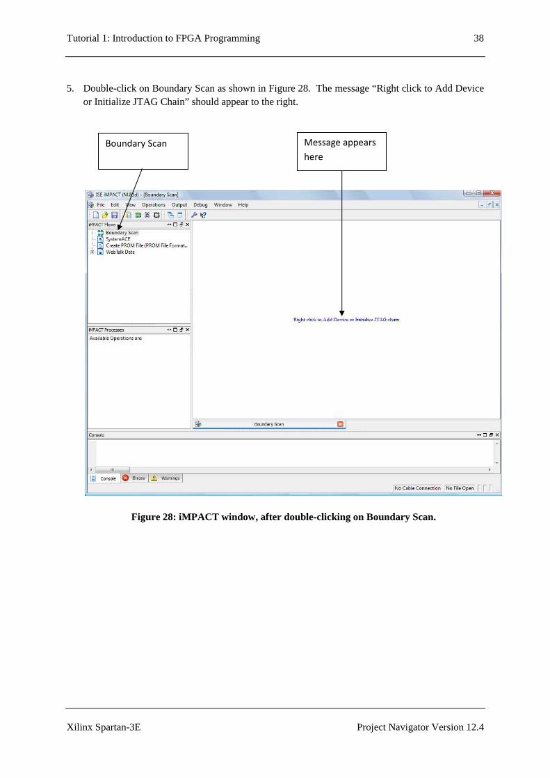
5. Double-click on Boundary Scan as shown in Figure 28. The message “Right click to Add Device
or Initialize JTAG Chain” should appear to the right.
Figure 28: iMPACT window, after double-clicking on Boundary Scan.
Boundary Scan Message appears
here

Tutorial 1: Introduction to FPGA Programming 39
Xilinx Spartan-3E Project Navigator Version 12.4
6. Right click on the text “Right click to Add Device or Initialize JTAG Chain”, and select Initialise Chain, as shown in Figure 29.
Figure 29: iMPACT window, showing Initialize Chain selected.
Tutorial 1: Introduction to FPGA Programming 40
Xilinx Spartan-3E Project Navigator Version 12.4
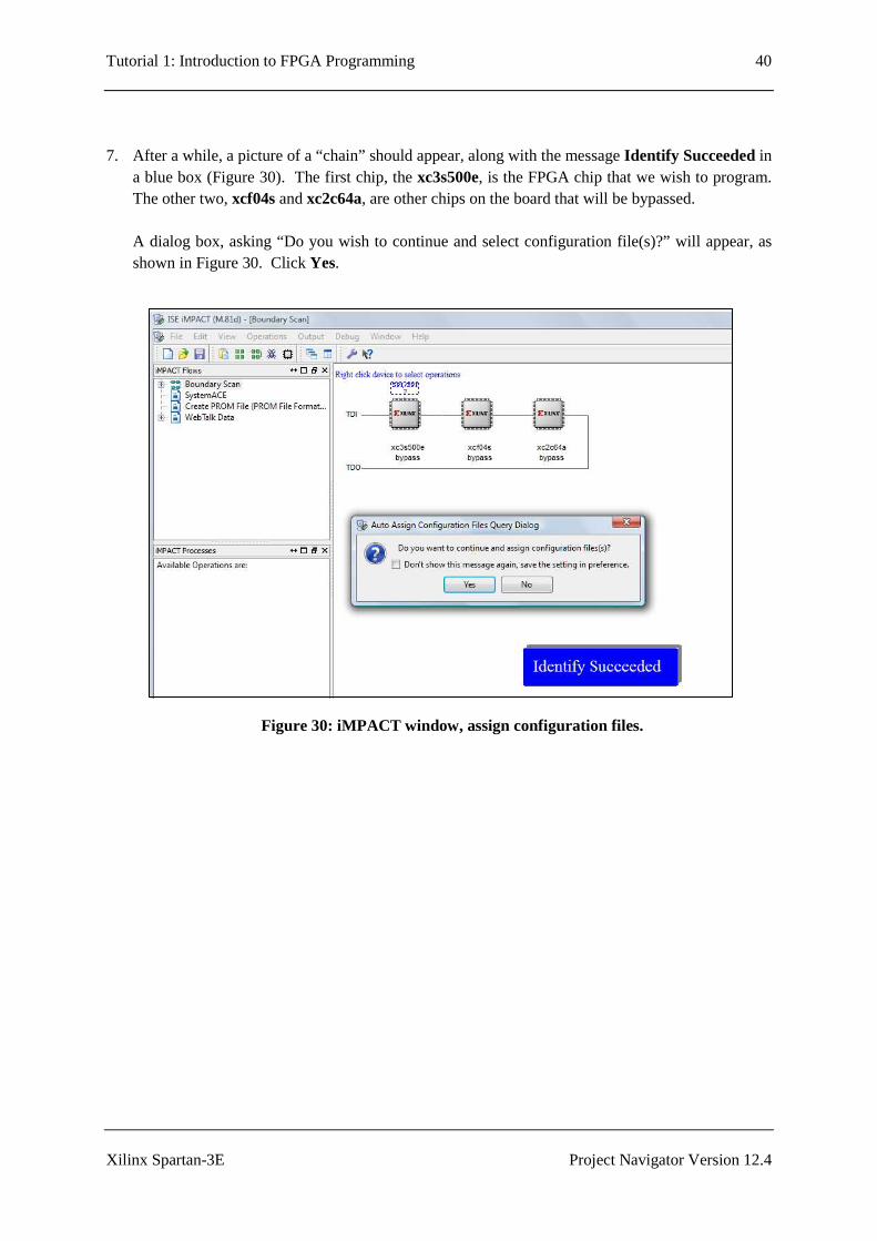
7. After a while, a picture of a “chain” should appear, along with the message Identify Succeeded in a blue box (Figure 30). The first chip, the xc3s500e, is the FPGA chip that we wish to program. The other two, xcf04s and xc2c64a, are other chips on the board that will be bypassed. A dialog box, asking “Do you wish to continue and select configuration file(s)?” will appear, as shown in Figure 30. Click Yes.
Figure 30: iMPACT window, assign configuration files.
Tutorial 1: Introduction to FPGA Programming 41
Xilinx Spartan-3E Project Navigator Version 12.4
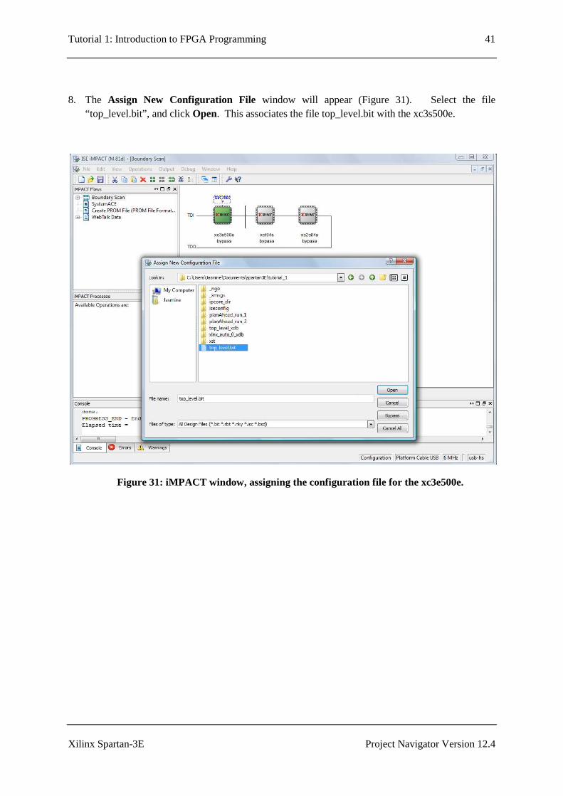
8. The Assign New Configuration File window will appear (Figure 31). Select the file “top_level.bit”, and click Open. This associates the file top_level.bit with the xc3s500e.
Figure 31: iMPACT window, assigning the configuration file for the xc3e500e.
Tutorial 1: Introduction to FPGA Programming 42
Xilinx Spartan-3E Project Navigator Version 12.4
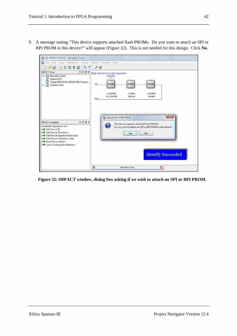
9. A message stating “This device supports attached flash PROMs. Do you want to attach an SPI or BPI PROM to this device?” will appear (Figure 32). This is not needed for this design. Click No.
Figure 32: iMPACT window, dialog box asking if we wish to attach an SPI or BPI PROM.
Tutorial 1: Introduction to FPGA Programming 43
Xilinx Spartan-3E Project Navigator Version 12.4
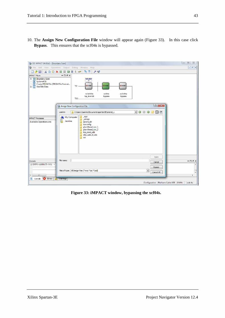
10. The Assign New Configuration File window will appear again (Figure 33). In this case click Bypass. This ensures that the xcf04s is bypassed.
Figure 33: iMPACT window, bypassing the xcf04s.
Tutorial 1: Introduction to FPGA Programming 44
Xilinx Spartan-3E Project Navigator Version 12.4
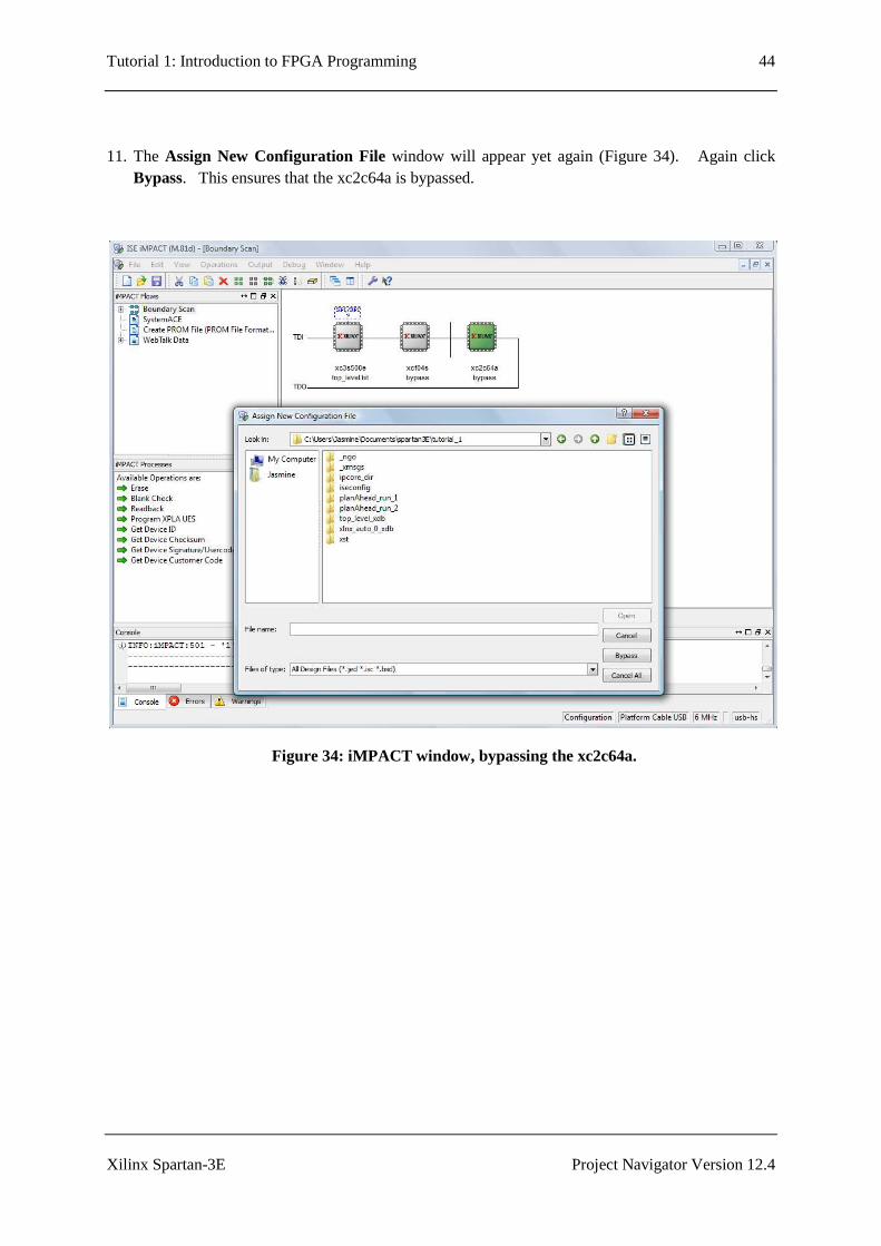
11. The Assign New Configuration File window will appear yet again (Figure 34). Again click Bypass. This ensures that the xc2c64a is bypassed.
Figure 34: iMPACT window, bypassing the xc2c64a.
Tutorial 1: Introduction to FPGA Programming 45
Xilinx Spartan-3E Project Navigator Version 12.4
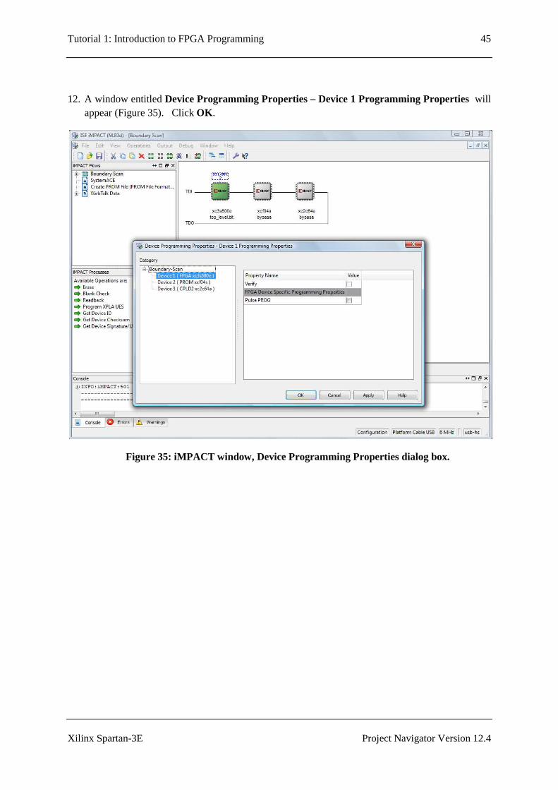
12. A window entitled Device Programming Properties – Device 1 Programming Properties will appear (Figure 35). Click OK .
Figure 35: iMPACT window, Device Programming Properties dialog box.
Tutorial 1: Introduction to FPGA Programming 46
Xilinx Spartan-3E Project Navigator Version 12.4
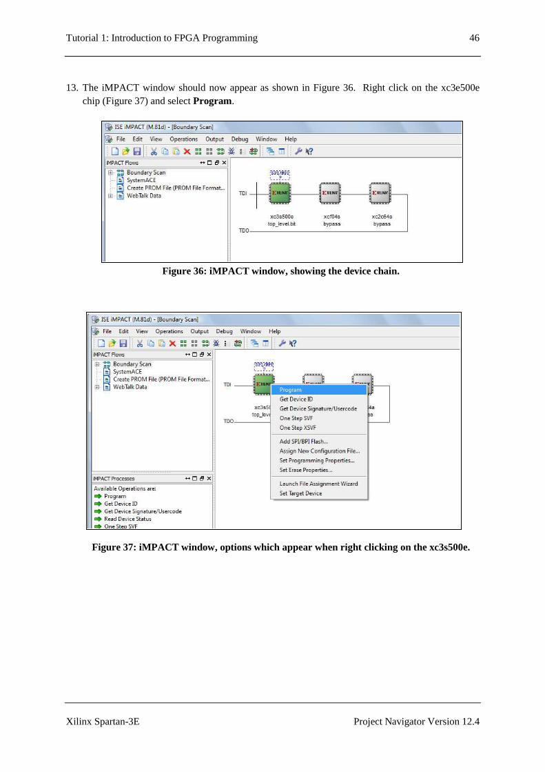
13. The iMPACT window should now appear as shown in Figure 36. Right click on the xc3e500e
chip (Figure 37) and select Program.
Figure 36: iMPACT window, showing the device chain.
Figure 37: iMPACT window, options which appear when right clicking on the xc3s500e.
Tutorial 1: Introduction to FPGA Programming 47
Xilinx Spartan-3E Project Navigator Version 12.4
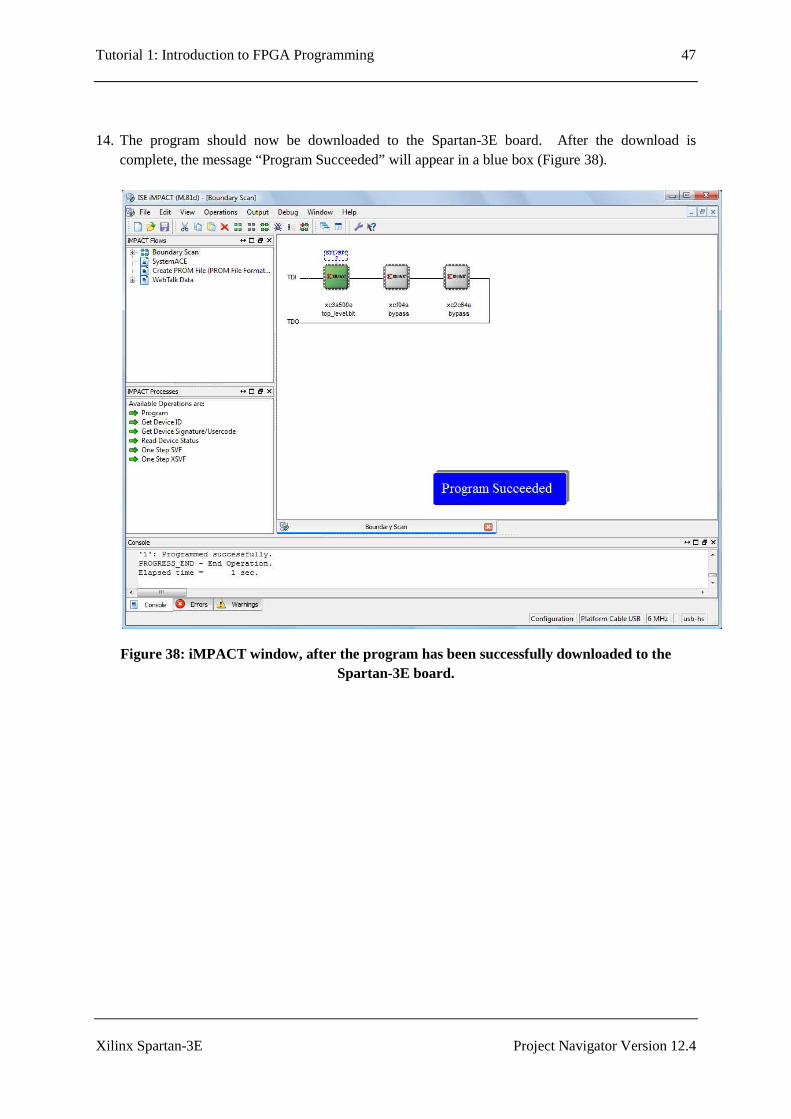
14. The program should now be downloaded to the Spartan-3E board. After the download is complete, the message “Program Succeeded” will appear in a blue box (Figure 38).
Figure 38: iMPACT window, after the program has been successfully downloaded to the Spartan-3E board.
Tutorial 1: Introduction to FPGA Programming 48
Xilinx Spartan-3E Project Navigator Version 12.4
3.9 Running the Program on the Spartan-3E Board
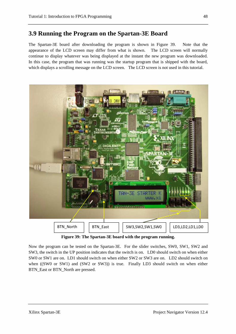
The Spartan-3E board after downloading the program is shown in Figure 39. Note that the appearance of the LCD screen may differ from what is shown. The LCD screen will normally continue to display whatever was being displayed at the instant the new program was downloaded. In this case, the program that was running was the startup program that is shipped with the board, which displays a scrolling message on the LCD screen. The LCD screen is not used in this tutorial.
Figure 39: The Spartan-3E board with the program running.
Now the program can be tested on the Spartan-3E. For the slider switches, SW0, SW1, SW2 and SW3, the switch in the UP position indicates that the switch is on. LD0 should switch on when either SW0 or SW1 are on. LD1 should switch on when either SW2 or SW3 are on. LD2 should switch on when ((SW0 or SW1) and (SW2 or SW3)) is true. Finally LD3 should switch on when either BTN_East or BTN_North are pressed.
BTN_North BTN_East LD3,LD2,LD1,LD0 SW3,SW2,SW1,SW0

Tutorial 1: Introduction to FPGA Programming 49
Xilinx Spartan-3E Project Navigator Version 12.4
4.0 Further Information
For further information about this tutorial, please contact:
Dr. Jasmine Banks School of Engineering Systems Queensland University of Technology GPO Box 2434, Brisbane 4001, AUSTRALIA
Email: [email protected] or [email protected].

Tutorial 1: Introduction to FPGA Programming 50
Xilinx Spartan-3E Project Navigator Version 12.4

Tutorial 1: Introduction to FPGA Programming 51
Xilinx Spartan-3E Project Navigator Version 12.4
5.0 References
[1] Spartan-3E FPGA Starter Kit Board User Guide, Online: http://www.xilinx.com/support/documentation/boards_and_kits/ug230.pdf, accessed 25 Jan 2011.
[2] Roth, C. H., Digital Systems Design Using VHDL, PWS Publishing Company, 1998.
[3] Roth, C. H. And Kinney, L. L., Fundamentals of Logic Design, 6th edition, CENGAGE Learning, 2010.
[4] Spartan-3E FPGA Starter Kit Board Design Examples, Online: http://www.xilinx.com/products/boards/s3estarter/reference_designs.htm, accessed 25 Jan 2011.

Tutorial 1: Introduction to FPGA Programming 52
Xilinx Spartan-3E Project Navigator Version 12.4
Related Documents