Tutorial 17. Modeling Evaporating Liquid Spray Introduction In this tutorial, the air-blast atomizer model in ANSYS FLUENT is used to predict the behavior of an evaporating methanol spray. Initially, the air flow is modeled without droplets. To predict the behavior of the spray, several other discrete-phase models, including collision and breakup, are used. This tutorial demonstrates how to do the following: • Define a spray injection for an air-blast atomizer. • Calculate a solution using the discrete phase model in ANSYS FLUENT. Prerequisites This tutorial is written with the assumption that you have completed Tutorial 1, and that you are familiar with the ANSYS FLUENT navigation pane and menu structure. Some steps in the setup and solution procedure will not be shown explicitly. Problem Description The geometry to be considered in this tutorial is shown in Figure 17.1. Methanol is cooled to -10 ◦ C before being introduced into an air-blast atomizer. The atomizer contains an inner air stream surrounded by a swirling annular stream. To make use of the periodicity of the problem, only a 30 ◦ section of the atomizer will be modeled. Release 12.0 c ANSYS, Inc. March 12, 2009 17-1

Welcome message from author
This document is posted to help you gain knowledge. Please leave a comment to let me know what you think about it! Share it to your friends and learn new things together.
Transcript
Tutorial 17. Modeling Evaporating Liquid Spray
Introduction
In this tutorial, the air-blast atomizer model in ANSYS FLUENT is used to predict thebehavior of an evaporating methanol spray. Initially, the air flow is modeled withoutdroplets. To predict the behavior of the spray, several other discrete-phase models,including collision and breakup, are used.
This tutorial demonstrates how to do the following:
• Define a spray injection for an air-blast atomizer.
• Calculate a solution using the discrete phase model in ANSYS FLUENT.
Prerequisites
This tutorial is written with the assumption that you have completed Tutorial 1, andthat you are familiar with the ANSYS FLUENT navigation pane and menu structure.Some steps in the setup and solution procedure will not be shown explicitly.
Problem Description
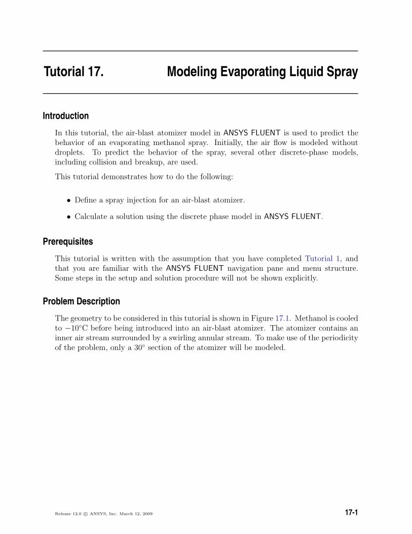
The geometry to be considered in this tutorial is shown in Figure 17.1. Methanol is cooledto −10◦C before being introduced into an air-blast atomizer. The atomizer contains aninner air stream surrounded by a swirling annular stream. To make use of the periodicityof the problem, only a 30◦ section of the atomizer will be modeled.
Release 12.0 c© ANSYS, Inc. March 12, 2009 17-1
Modeling Evaporating Liquid Spray
ZY
X
inner air stream
swirling annular stream
Figure 17.1: Problem Specification
Setup and Solution
Preparation
1. Download evaporate_liquid.zip from the User Services Center to your workingfolder (as described in Tutorial 1).
2. Unzip evaporate_liquid.zip.
The mesh file sector.msh can be found in the evaporate liquid folder createdafter unzipping the file.
3. Use FLUENT Launcher to start the 3D version of ANSYS FLUENT.
For more information about FLUENT Launcher, see Section 1.1.2 in the separateUser’s Guide.
Note: The Display Options are enabled by default. Therefore, after you read in the mesh,it will be displayed in the embedded graphics window.
17-2 Release 12.0 c© ANSYS, Inc. March 12, 2009
Modeling Evaporating Liquid Spray
Step 1: Mesh
1. Read in the mesh file sector.msh.
File −→ Read −→Mesh...
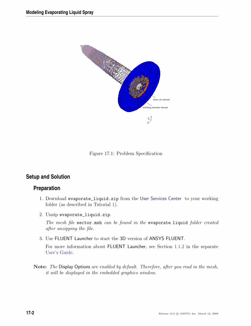
2. Change the periodic type of periodic-a to rotational.
Boundary Conditions −→ periodic-a −→ Edit...
(a) Select Rotational in the Periodic Type list.
(b) Click OK to close the Periodic dialog box.
3. In a similar manner, change the periodic type of periodic-b to rotational.
Step 2: General Settings
General
1. Check the mesh.
General −→ Check
ANSYS FLUENT will perform various checks on the mesh and report the progressin the console. Ensure that the reported minimum volume is a positive number.
Release 12.0 c© ANSYS, Inc. March 12, 2009 17-3

Modeling Evaporating Liquid Spray
2. Display the mesh.
General −→ Display...
(a) Enable Faces in the Options group box.
(b) Select only atomizer-wall, central air, and swirling air from the Surfaces selectionlist.
(c) Click the Colors... button to open the Mesh Colors dialog box.
i. Select wall from the Types selection list.
ii. Select pink from the Colors selection list.
iii. Close the Mesh Colors dialog box.
(d) Click Display and close the Mesh Display dialog box.
17-4 Release 12.0 c© ANSYS, Inc. March 12, 2009
Modeling Evaporating Liquid Spray
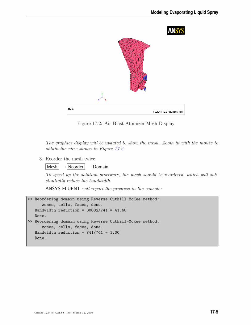
Figure 17.2: Air-Blast Atomizer Mesh Display
The graphics display will be updated to show the mesh. Zoom in with the mouse toobtain the view shown in Figure 17.2.
3. Reorder the mesh twice.
Mesh −→ Reorder −→Domain
To speed up the solution procedure, the mesh should be reordered, which will sub-stantially reduce the bandwidth.
ANSYS FLUENT will report the progress in the console:
>> Reordering domain using Reverse Cuthill-McKee method:zones, cells, faces, done.
Bandwidth reduction = 30882/741 = 41.68Done.
>> Reordering domain using Reverse Cuthill-McKee method:zones, cells, faces, done.
Bandwidth reduction = 741/741 = 1.00Done.
Release 12.0 c© ANSYS, Inc. March 12, 2009 17-5
Modeling Evaporating Liquid Spray
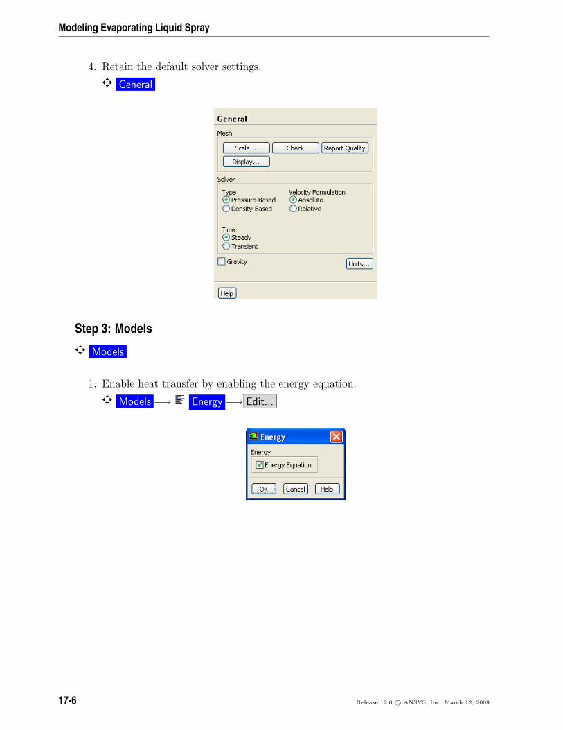
4. Retain the default solver settings.
General
Step 3: Models
Models
1. Enable heat transfer by enabling the energy equation.
Models −→ Energy −→ Edit...
17-6 Release 12.0 c© ANSYS, Inc. March 12, 2009
Modeling Evaporating Liquid Spray
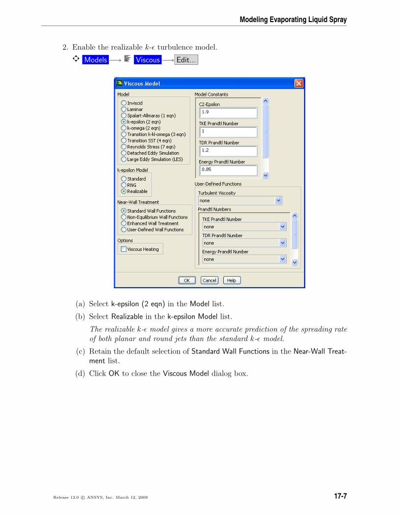
2. Enable the realizable k-ε turbulence model.
Models −→ Viscous −→ Edit...
(a) Select k-epsilon (2 eqn) in the Model list.
(b) Select Realizable in the k-epsilon Model list.
The realizable k-ε model gives a more accurate prediction of the spreading rateof both planar and round jets than the standard k-ε model.
(c) Retain the default selection of Standard Wall Functions in the Near-Wall Treat-ment list.
(d) Click OK to close the Viscous Model dialog box.
Release 12.0 c© ANSYS, Inc. March 12, 2009 17-7
Modeling Evaporating Liquid Spray
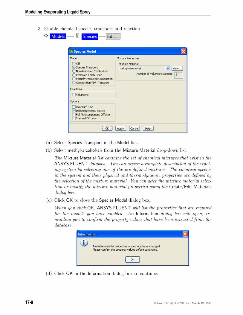
3. Enable chemical species transport and reaction.
Models −→ Species −→ Edit...
(a) Select Species Transport in the Model list.
(b) Select methyl-alcohol-air from the Mixture Material drop-down list.
The Mixture Material list contains the set of chemical mixtures that exist in theANSYS FLUENT database. You can access a complete description of the react-ing system by selecting one of the pre-defined mixtures. The chemical speciesin the system and their physical and thermodynamic properties are defined bythe selection of the mixture material. You can alter the mixture material selec-tion or modify the mixture material properties using the Create/Edit Materialsdialog box.
(c) Click OK to close the Species Model dialog box.
When you click OK, ANSYS FLUENT will list the properties that are requiredfor the models you have enabled. An Information dialog box will open, re-minding you to confirm the property values that have been extracted from thedatabase.
(d) Click OK in the Information dialog box to continue.
17-8 Release 12.0 c© ANSYS, Inc. March 12, 2009
Modeling Evaporating Liquid Spray
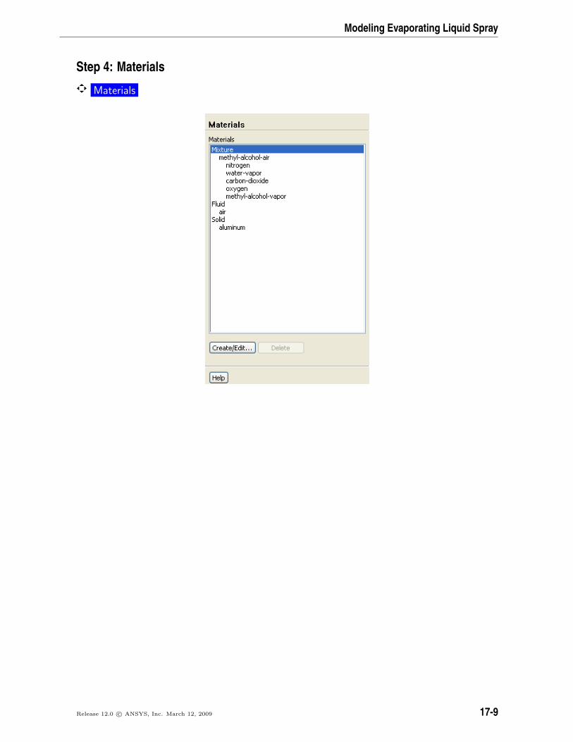
Step 4: Materials
Materials
Release 12.0 c© ANSYS, Inc. March 12, 2009 17-9
Modeling Evaporating Liquid Spray
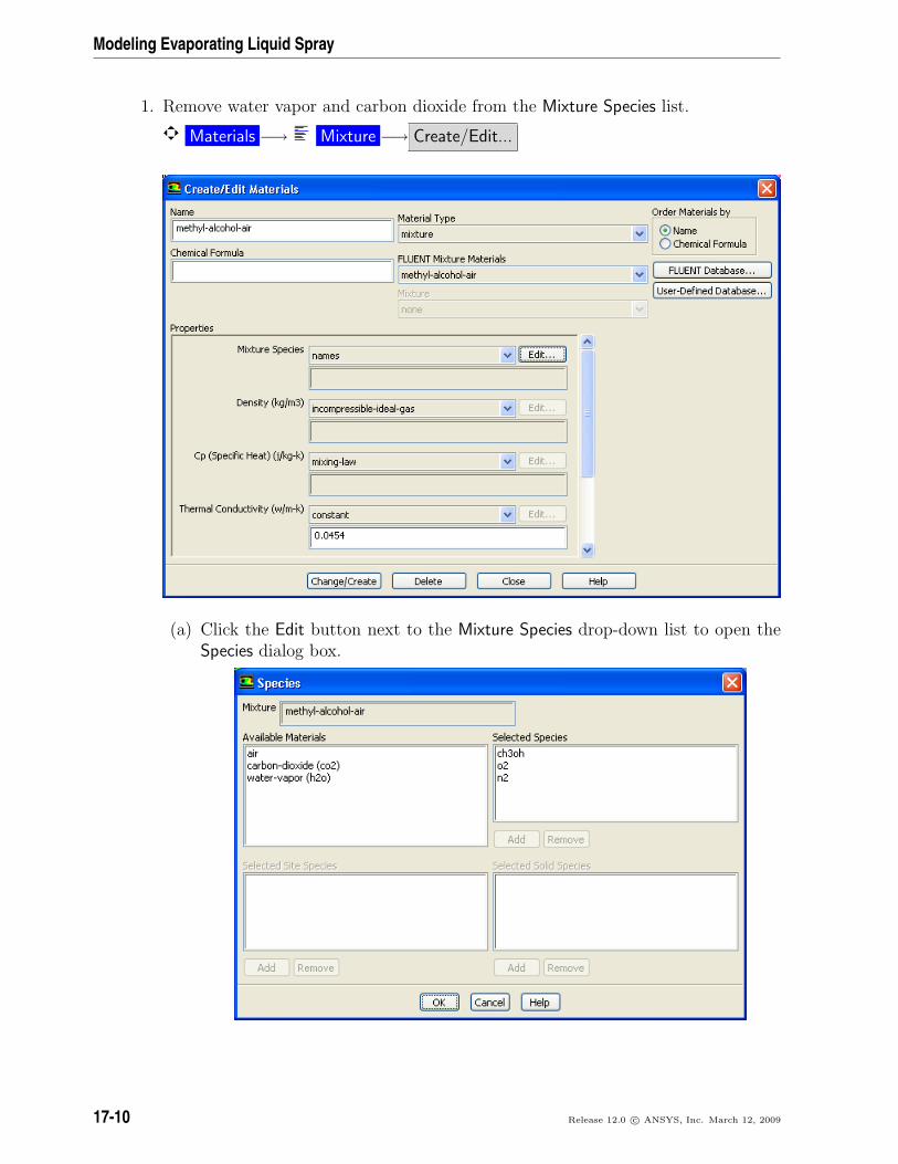
1. Remove water vapor and carbon dioxide from the Mixture Species list.
Materials −→ Mixture −→ Create/Edit...
(a) Click the Edit button next to the Mixture Species drop-down list to open theSpecies dialog box.
17-10 Release 12.0 c© ANSYS, Inc. March 12, 2009
Modeling Evaporating Liquid Spray
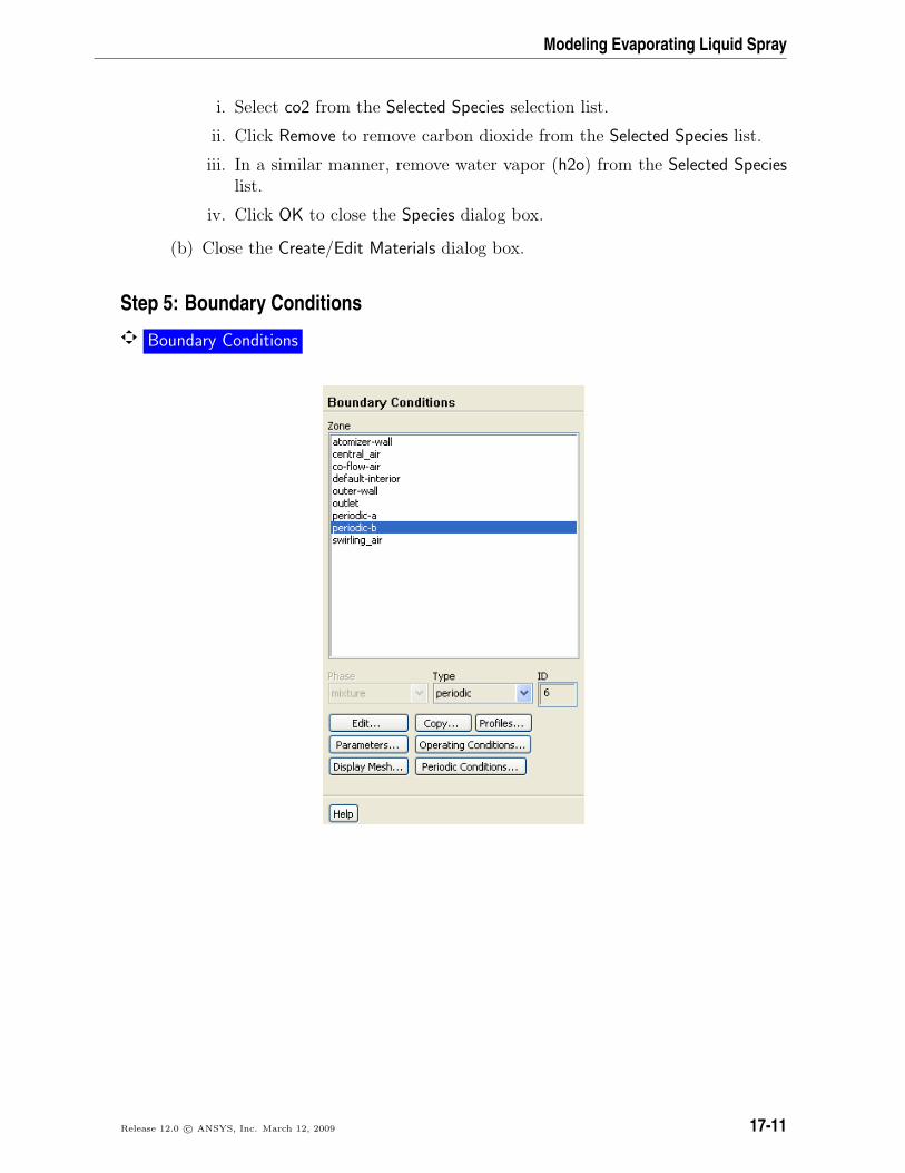
i. Select co2 from the Selected Species selection list.
ii. Click Remove to remove carbon dioxide from the Selected Species list.
iii. In a similar manner, remove water vapor (h2o) from the Selected Specieslist.
iv. Click OK to close the Species dialog box.
(b) Close the Create/Edit Materials dialog box.
Step 5: Boundary Conditions
Boundary Conditions
Release 12.0 c© ANSYS, Inc. March 12, 2009 17-11
Modeling Evaporating Liquid Spray
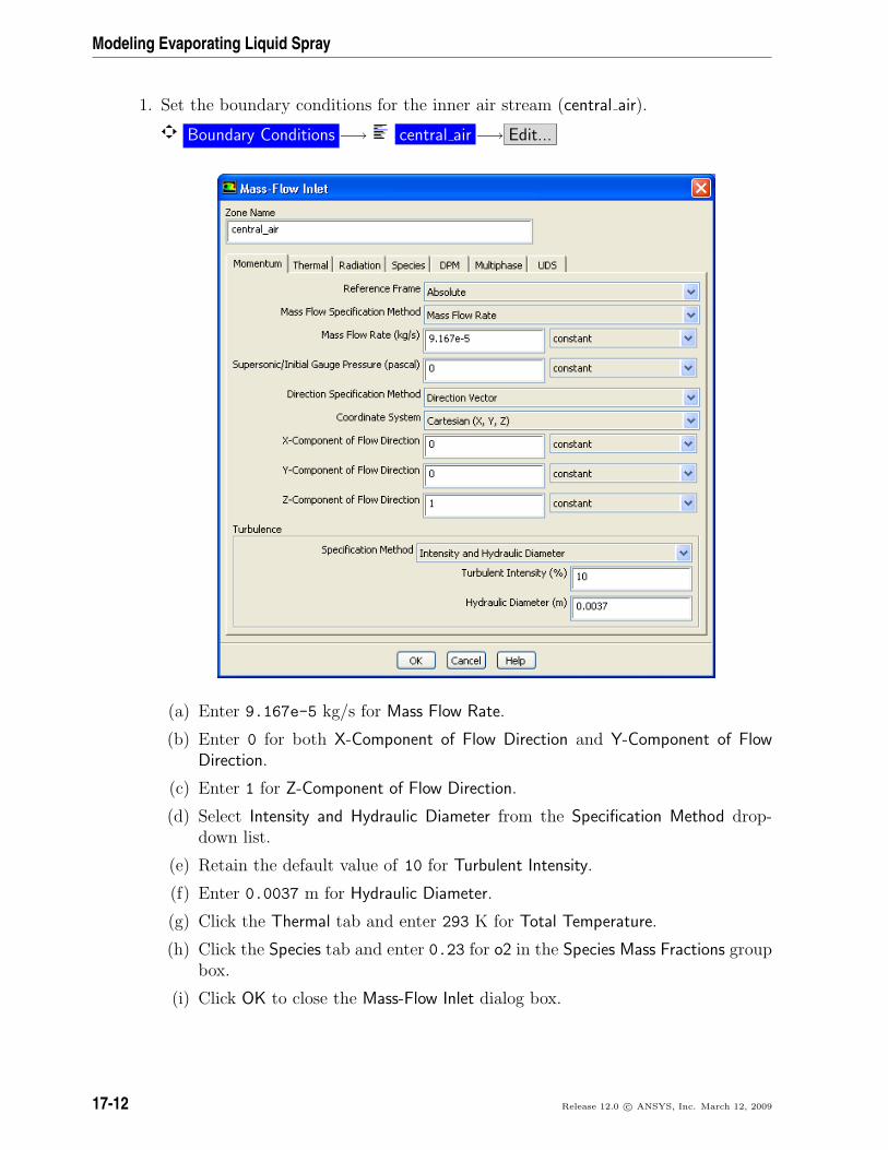
1. Set the boundary conditions for the inner air stream (central air).
Boundary Conditions −→ central air −→ Edit...
(a) Enter 9.167e-5 kg/s for Mass Flow Rate.
(b) Enter 0 for both X-Component of Flow Direction and Y-Component of FlowDirection.
(c) Enter 1 for Z-Component of Flow Direction.
(d) Select Intensity and Hydraulic Diameter from the Specification Method drop-down list.
(e) Retain the default value of 10 for Turbulent Intensity.
(f) Enter 0.0037 m for Hydraulic Diameter.
(g) Click the Thermal tab and enter 293 K for Total Temperature.
(h) Click the Species tab and enter 0.23 for o2 in the Species Mass Fractions groupbox.
(i) Click OK to close the Mass-Flow Inlet dialog box.
17-12 Release 12.0 c© ANSYS, Inc. March 12, 2009
Modeling Evaporating Liquid Spray
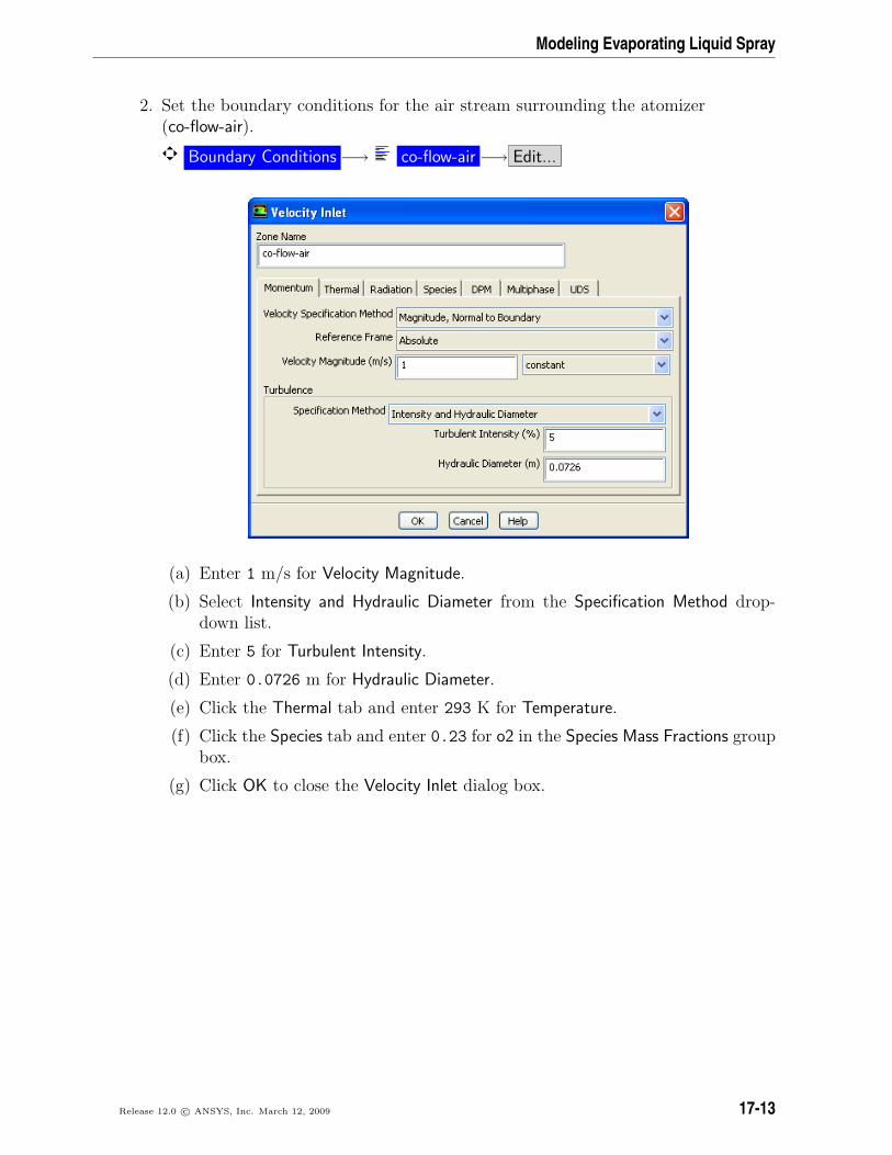
2. Set the boundary conditions for the air stream surrounding the atomizer(co-flow-air).
Boundary Conditions −→ co-flow-air −→ Edit...
(a) Enter 1 m/s for Velocity Magnitude.
(b) Select Intensity and Hydraulic Diameter from the Specification Method drop-down list.
(c) Enter 5 for Turbulent Intensity.
(d) Enter 0.0726 m for Hydraulic Diameter.
(e) Click the Thermal tab and enter 293 K for Temperature.
(f) Click the Species tab and enter 0.23 for o2 in the Species Mass Fractions groupbox.
(g) Click OK to close the Velocity Inlet dialog box.
Release 12.0 c© ANSYS, Inc. March 12, 2009 17-13
Modeling Evaporating Liquid Spray
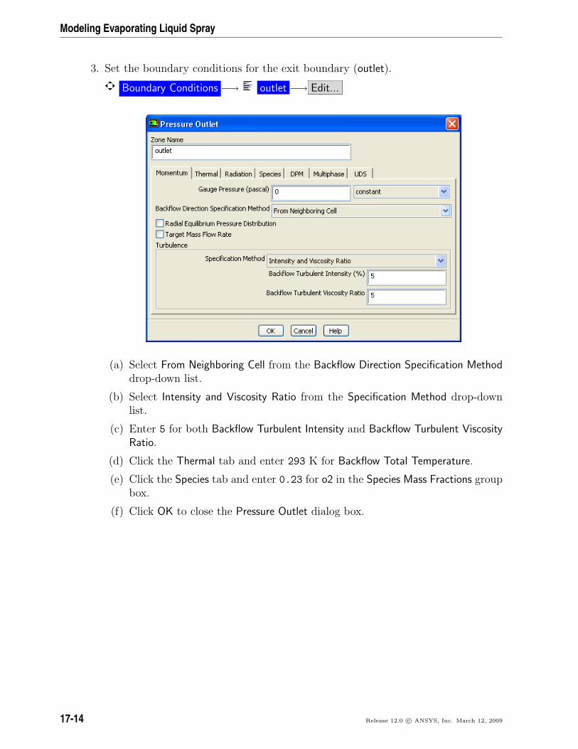
3. Set the boundary conditions for the exit boundary (outlet).
Boundary Conditions −→ outlet −→ Edit...
(a) Select From Neighboring Cell from the Backflow Direction Specification Methoddrop-down list.
(b) Select Intensity and Viscosity Ratio from the Specification Method drop-downlist.
(c) Enter 5 for both Backflow Turbulent Intensity and Backflow Turbulent ViscosityRatio.
(d) Click the Thermal tab and enter 293 K for Backflow Total Temperature.
(e) Click the Species tab and enter 0.23 for o2 in the Species Mass Fractions groupbox.
(f) Click OK to close the Pressure Outlet dialog box.
17-14 Release 12.0 c© ANSYS, Inc. March 12, 2009
Modeling Evaporating Liquid Spray
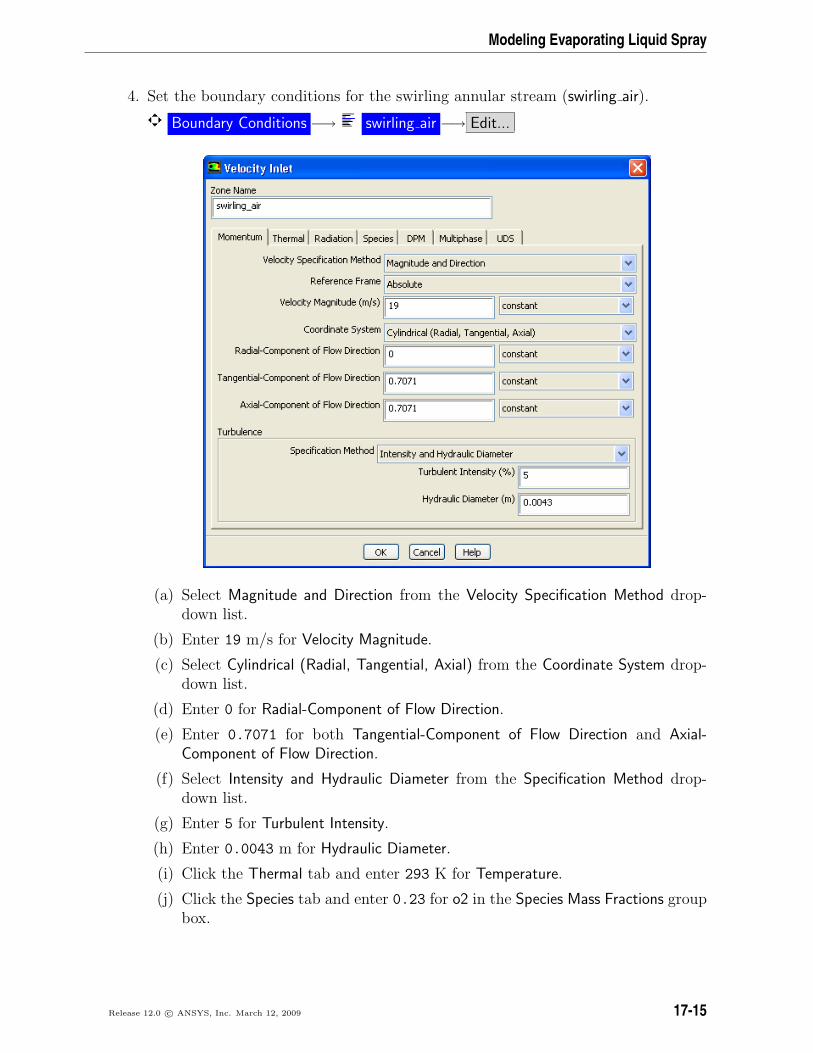
4. Set the boundary conditions for the swirling annular stream (swirling air).
Boundary Conditions −→ swirling air −→ Edit...
(a) Select Magnitude and Direction from the Velocity Specification Method drop-down list.
(b) Enter 19 m/s for Velocity Magnitude.
(c) Select Cylindrical (Radial, Tangential, Axial) from the Coordinate System drop-down list.
(d) Enter 0 for Radial-Component of Flow Direction.
(e) Enter 0.7071 for both Tangential-Component of Flow Direction and Axial-Component of Flow Direction.
(f) Select Intensity and Hydraulic Diameter from the Specification Method drop-down list.
(g) Enter 5 for Turbulent Intensity.
(h) Enter 0.0043 m for Hydraulic Diameter.
(i) Click the Thermal tab and enter 293 K for Temperature.
(j) Click the Species tab and enter 0.23 for o2 in the Species Mass Fractions groupbox.
Release 12.0 c© ANSYS, Inc. March 12, 2009 17-15
Modeling Evaporating Liquid Spray
(k) Click OK to close the Velocity Inlet dialog box.
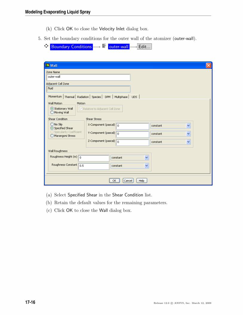
5. Set the boundary conditions for the outer wall of the atomizer (outer-wall).
Boundary Conditions −→ outer-wall −→ Edit...
(a) Select Specified Shear in the Shear Condition list.
(b) Retain the default values for the remaining parameters.
(c) Click OK to close the Wall dialog box.
17-16 Release 12.0 c© ANSYS, Inc. March 12, 2009
Modeling Evaporating Liquid Spray
Step 6: Initial Solution Without Droplets
The airflow will first be solved and analyzed without droplets.
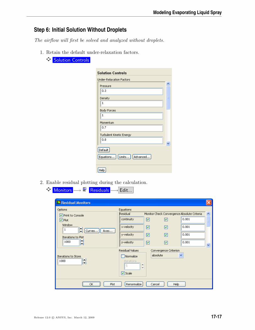
1. Retain the default under-relaxation factors.
Solution Controls
2. Enable residual plotting during the calculation.
Monitors −→ Residuals −→ Edit...
Release 12.0 c© ANSYS, Inc. March 12, 2009 17-17
Modeling Evaporating Liquid Spray
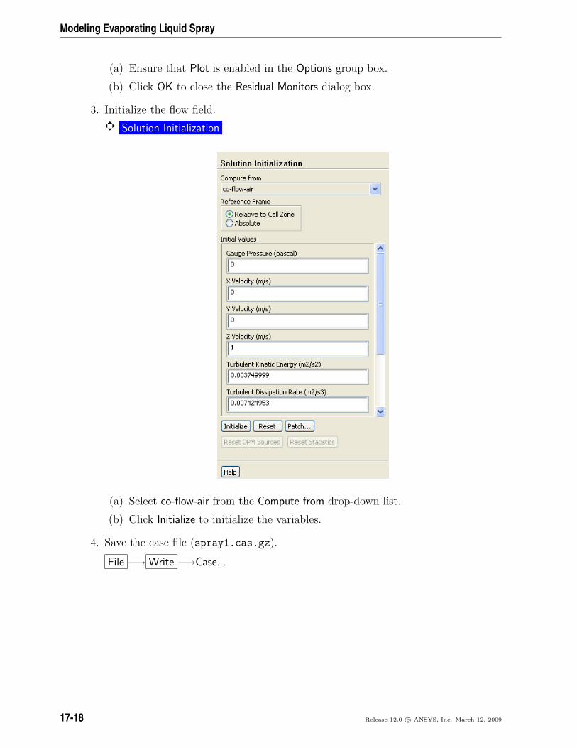
(a) Ensure that Plot is enabled in the Options group box.
(b) Click OK to close the Residual Monitors dialog box.
3. Initialize the flow field.
Solution Initialization
(a) Select co-flow-air from the Compute from drop-down list.
(b) Click Initialize to initialize the variables.
4. Save the case file (spray1.cas.gz).
File −→ Write −→Case...
17-18 Release 12.0 c© ANSYS, Inc. March 12, 2009

Modeling Evaporating Liquid Spray
5. Start the calculation by requesting 300 iterations.
Run Calculation
(a) Enter 300 for Number of Iterations.
(b) Click Calculate.
The solution will converge in approximately 250 iterations.
6. Save the case and data files (spray1.cas.gz and spray1.dat.gz).
File −→ Write −→Case & Data...
Note: ANSYS FLUENT will ask you to confirm that the previous case file is to beoverwritten.
7. Create a clip plane to examine the flow field at the midpoint of the atomizer section.
Surface −→Iso-Surface...
(a) Select Mesh... and Angular Coordinate from the Surface of Constant drop-downlists.
(b) Click Compute to update the minimum and maximum values.
(c) Enter 15 for Iso-Values.
(d) Enter angle=15 for New Surface Name.
(e) Click Create to create the isosurface.
(f) Close the Iso-Surface dialog box.
Release 12.0 c© ANSYS, Inc. March 12, 2009 17-19

Modeling Evaporating Liquid Spray
8. Review the current state of the solution by examining contours of velocity magni-tude (Figure 17.3).
Graphics and Animations −→ Contours −→ Set Up...
(a) Enable Filled in the Options group box
(b) Select Velocity... and Velocity Magnitude from the Contours of drop-down lists.
(c) Enable Draw Mesh.
The Mesh Display dialog box will open.
17-20 Release 12.0 c© ANSYS, Inc. March 12, 2009
Modeling Evaporating Liquid Spray
i. Retain the current mesh display settings.
ii. Close the Mesh Display dialog box.
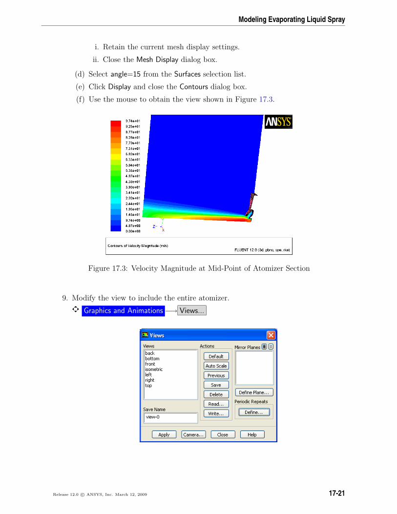
(d) Select angle=15 from the Surfaces selection list.
(e) Click Display and close the Contours dialog box.
(f) Use the mouse to obtain the view shown in Figure 17.3.
Figure 17.3: Velocity Magnitude at Mid-Point of Atomizer Section
9. Modify the view to include the entire atomizer.
Graphics and Animations −→ Views...
Release 12.0 c© ANSYS, Inc. March 12, 2009 17-21

Modeling Evaporating Liquid Spray
(a) Click the Define... button to open the Graphics Periodicity dialog box.
i. Select fluid from the Cell Zones selection list.
ii. Retain the selection of Rotational in the Periodic Type list.
iii. Retain the value of 12 for Number of Repeats.
iv. Click Set and close the Graphics Periodicity dialog box.
The graphics display will be updated to show the entire atomizer.
(b) Click Apply and close the Views dialog box.
10. Display pathlines of the air in the swirling annular stream (Figure 17.4).
Graphics and Animations −→ Pathlines −→ Set Up...
17-22 Release 12.0 c© ANSYS, Inc. March 12, 2009
Modeling Evaporating Liquid Spray
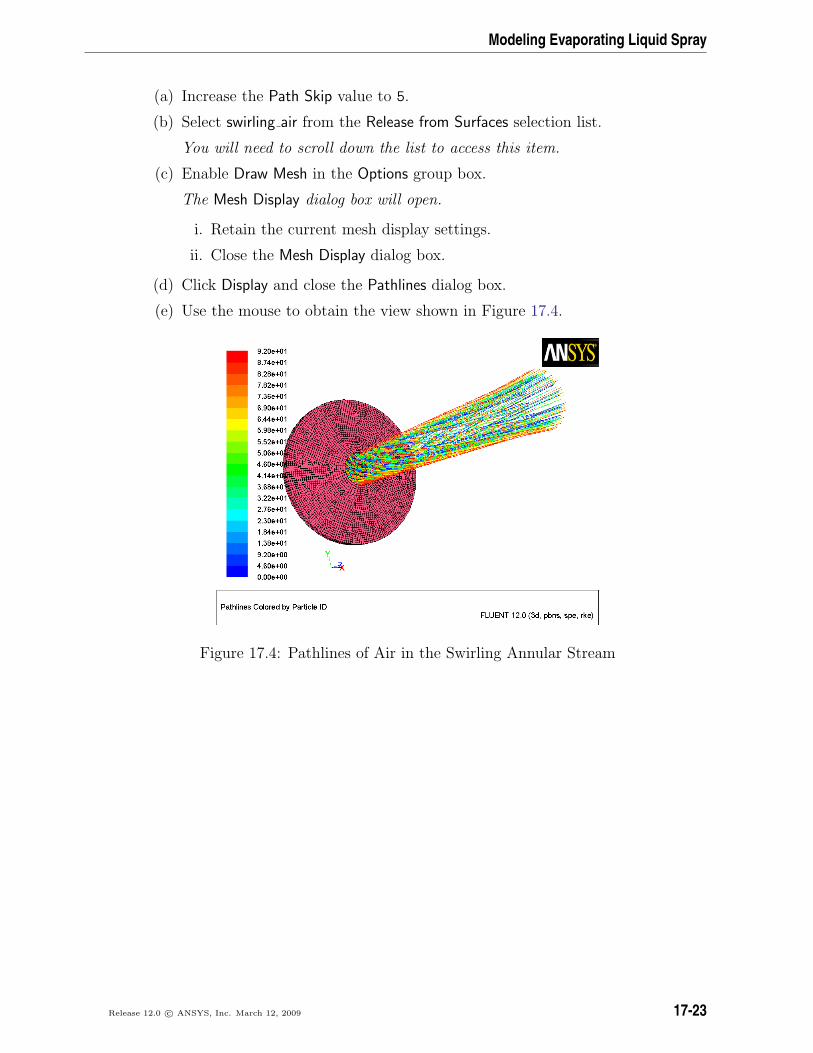
(a) Increase the Path Skip value to 5.
(b) Select swirling air from the Release from Surfaces selection list.
You will need to scroll down the list to access this item.
(c) Enable Draw Mesh in the Options group box.
The Mesh Display dialog box will open.
i. Retain the current mesh display settings.
ii. Close the Mesh Display dialog box.
(d) Click Display and close the Pathlines dialog box.
(e) Use the mouse to obtain the view shown in Figure 17.4.
Figure 17.4: Pathlines of Air in the Swirling Annular Stream
Release 12.0 c© ANSYS, Inc. March 12, 2009 17-23
Modeling Evaporating Liquid Spray
Step 7: Create a Spray Injection
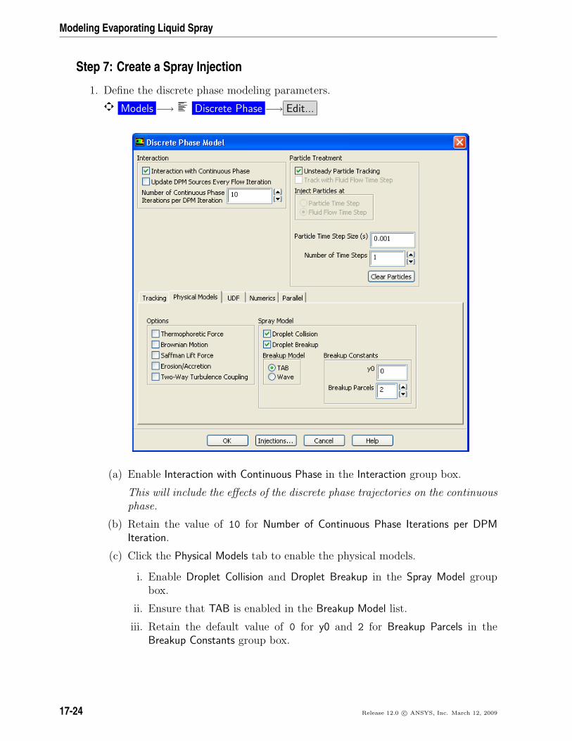
1. Define the discrete phase modeling parameters.
Models −→ Discrete Phase −→ Edit...
(a) Enable Interaction with Continuous Phase in the Interaction group box.
This will include the effects of the discrete phase trajectories on the continuousphase.
(b) Retain the value of 10 for Number of Continuous Phase Iterations per DPMIteration.
(c) Click the Physical Models tab to enable the physical models.
i. Enable Droplet Collision and Droplet Breakup in the Spray Model groupbox.
ii. Ensure that TAB is enabled in the Breakup Model list.
iii. Retain the default value of 0 for y0 and 2 for Breakup Parcels in theBreakup Constants group box.
17-24 Release 12.0 c© ANSYS, Inc. March 12, 2009
Modeling Evaporating Liquid Spray
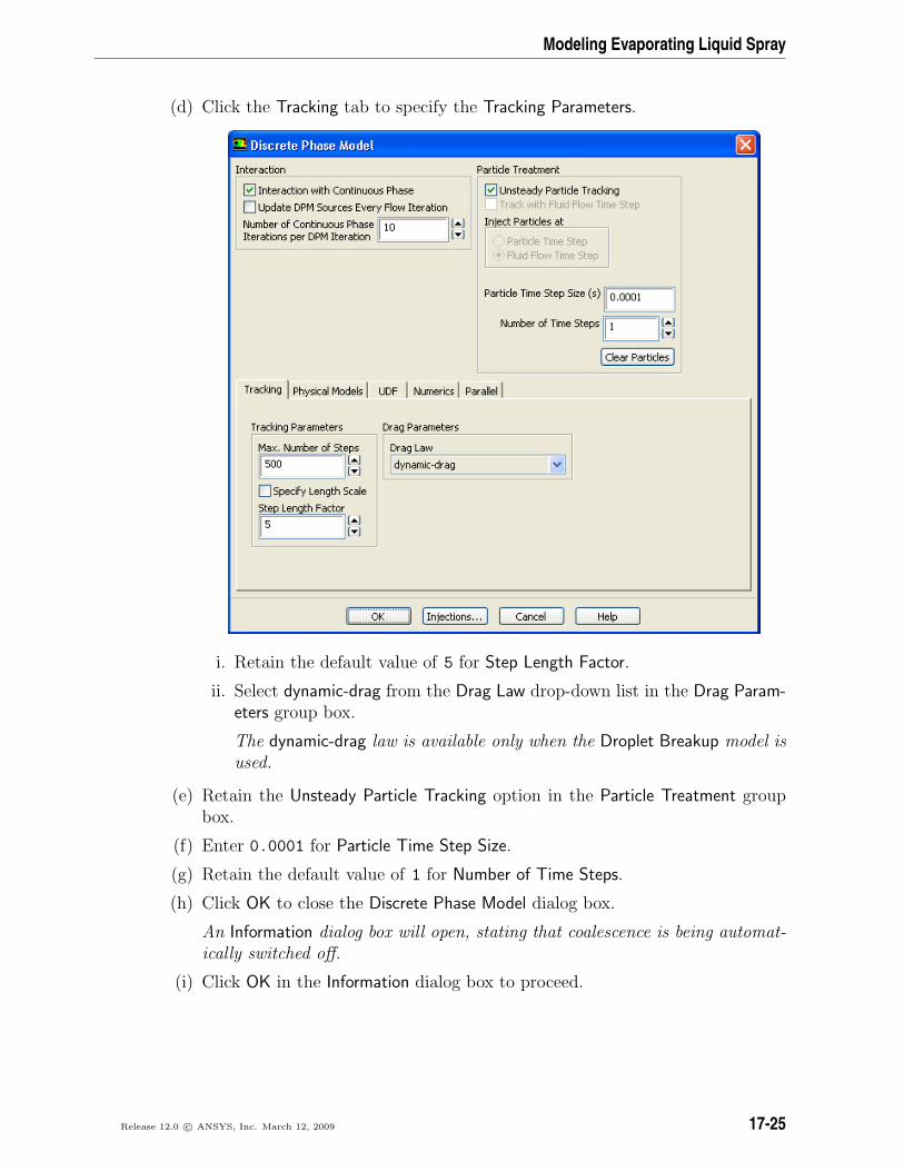
(d) Click the Tracking tab to specify the Tracking Parameters.
i. Retain the default value of 5 for Step Length Factor.
ii. Select dynamic-drag from the Drag Law drop-down list in the Drag Param-eters group box.
The dynamic-drag law is available only when the Droplet Breakup model isused.
(e) Retain the Unsteady Particle Tracking option in the Particle Treatment groupbox.
(f) Enter 0.0001 for Particle Time Step Size.
(g) Retain the default value of 1 for Number of Time Steps.
(h) Click OK to close the Discrete Phase Model dialog box.
An Information dialog box will open, stating that coalescence is being automat-ically switched off.
(i) Click OK in the Information dialog box to proceed.
Release 12.0 c© ANSYS, Inc. March 12, 2009 17-25
Modeling Evaporating Liquid Spray
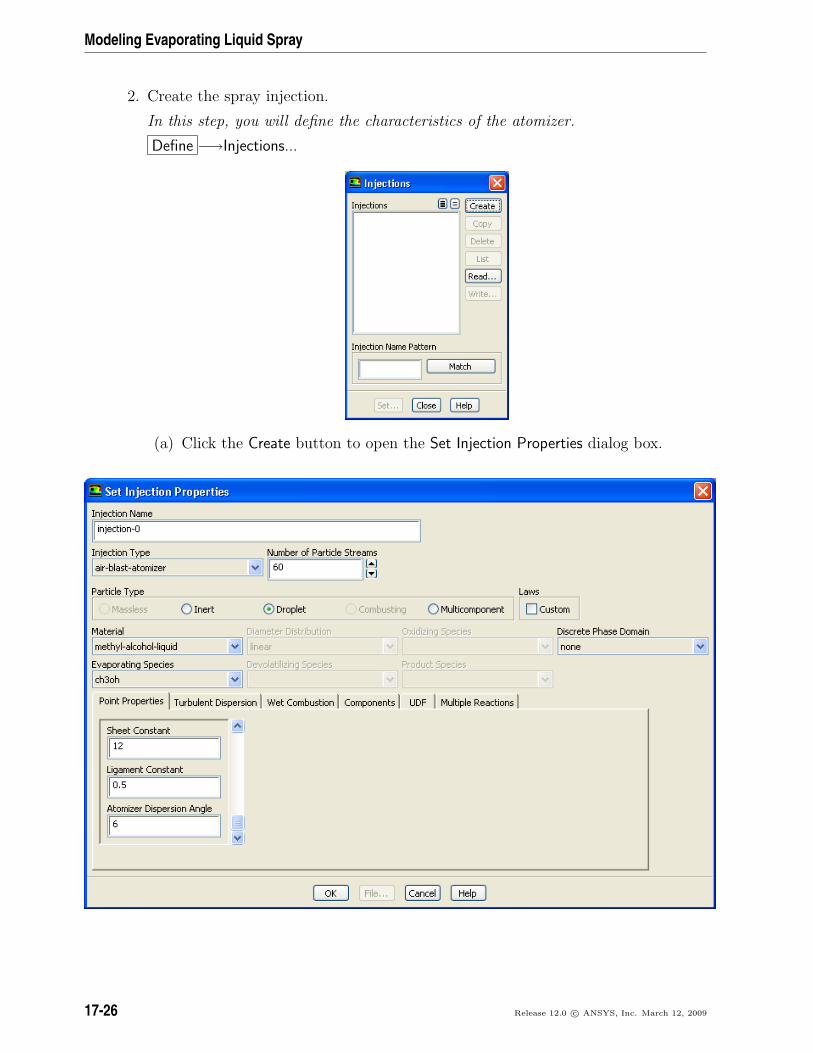
2. Create the spray injection.
In this step, you will define the characteristics of the atomizer.
Define −→Injections...
(a) Click the Create button to open the Set Injection Properties dialog box.
17-26 Release 12.0 c© ANSYS, Inc. March 12, 2009
Modeling Evaporating Liquid Spray
(b) Select air-blast-atomizer from the Injection Type drop-down list.
(c) Enter 60 for Number of Particle Streams.
This option controls the number of droplet parcels that are introduced into thedomain at every time step.
(d) Select Droplet in the Particle Type group box.
(e) Select methyl-alcohol-liquid from the Material drop-down list.
(f) Enter 0, 0, and 0.0015 for X-Position, Y-Position, and Z-Position, respectively,in the Point Properties tab.
Scroll down the list to see the remaining point properties.
(g) Retain the default values of 0, 0, and 1 for X-Axis, Y-Axis, and Z-Axis, respec-tively.
(h) Enter 263 K for Temperature.
(i) Enter 8.5e-5 kg/s for Flow Rate.
This is the methanol flow rate for a 30-degree section of the atomizer. Theactual atomizer flow rate is 12 times this value.
(j) Retain the default Start Time of 0 s and enter 100 s for the Stop Time.
For this problem, the injection should begin at t = 0 and not stop until longafter the time period of interest. A large value for the stop time (e.g., 100 s)will ensure that the injection will essentially never stop.
(k) Enter 0.0035 m for the Injector Inner Diameter and 0.0045 m for the InjectorOuter Diameter.
(l) Enter -45 degrees for Spray Half Angle.
The spray angle is the angle between the liquid sheet trajectory and the injectorcenterline. In this case, the value is negative because the sheet is initiallyconverging toward the centerline.
(m) Enter 82.6 m/s for the Relative Velocity.
The relative velocity is the expected relative velocity between the atomizing airand the liquid sheet.
(n) Retain the default Azimuthal Start Angle of 0 degrees and enter 30 degrees forthe Azimuthal Stop Angle.
This will restrict the injection to the 30-degree section of the atomizer that isbeing modeled.
Release 12.0 c© ANSYS, Inc. March 12, 2009 17-27
Modeling Evaporating Liquid Spray
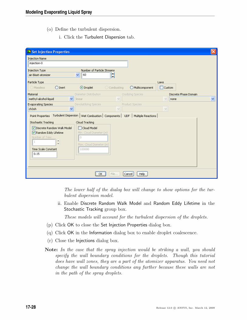
(o) Define the turbulent dispersion.
i. Click the Turbulent Dispersion tab.
The lower half of the dialog box will change to show options for the tur-bulent dispersion model.
ii. Enable Discrete Random Walk Model and Random Eddy Lifetime in theStochastic Tracking group box.
These models will account for the turbulent dispersion of the droplets.
(p) Click OK to close the Set Injection Properties dialog box.
(q) Click OK in the Information dialog box to enable droplet coalescence.
(r) Close the Injections dialog box.
Note: In the case that the spray injection would be striking a wall, you shouldspecify the wall boundary conditions for the droplets. Though this tutorialdoes have wall zones, they are a part of the atomizer apparatus. You need notchange the wall boundary conditions any further because these walls are notin the path of the spray droplets.
17-28 Release 12.0 c© ANSYS, Inc. March 12, 2009
Modeling Evaporating Liquid Spray
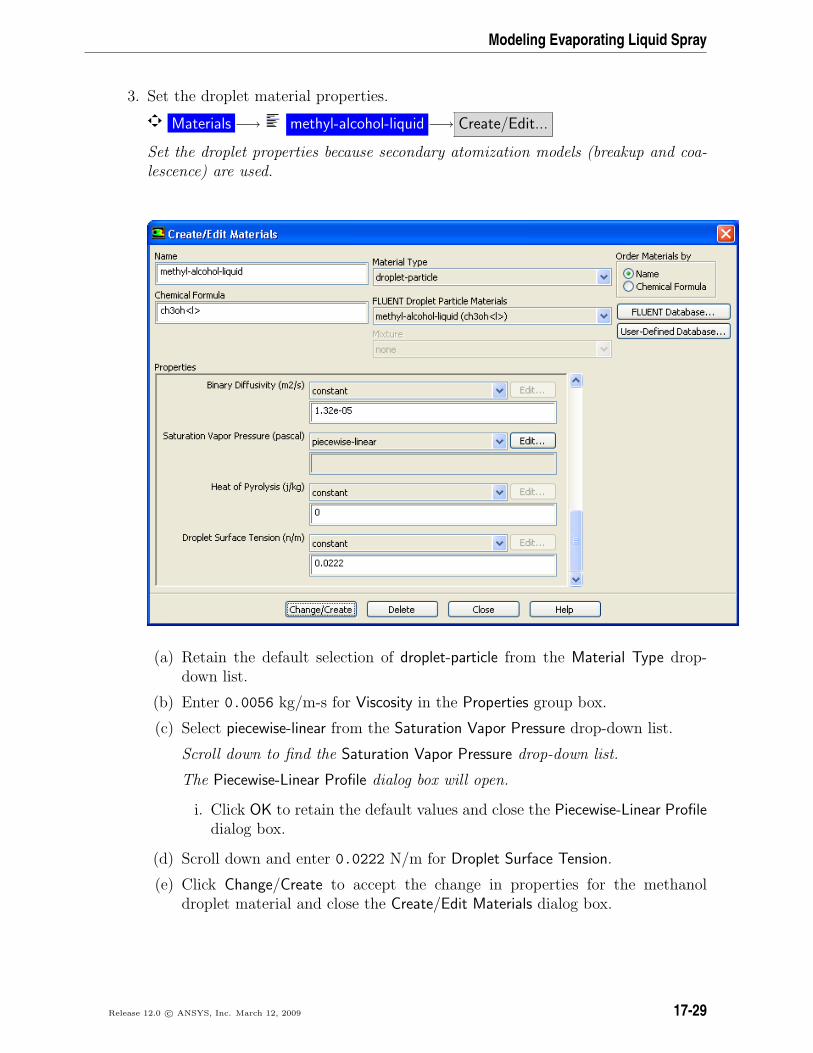
3. Set the droplet material properties.
Materials −→ methyl-alcohol-liquid −→ Create/Edit...
Set the droplet properties because secondary atomization models (breakup and coa-lescence) are used.
(a) Retain the default selection of droplet-particle from the Material Type drop-down list.
(b) Enter 0.0056 kg/m-s for Viscosity in the Properties group box.
(c) Select piecewise-linear from the Saturation Vapor Pressure drop-down list.
Scroll down to find the Saturation Vapor Pressure drop-down list.
The Piecewise-Linear Profile dialog box will open.
i. Click OK to retain the default values and close the Piecewise-Linear Profiledialog box.
(d) Scroll down and enter 0.0222 N/m for Droplet Surface Tension.
(e) Click Change/Create to accept the change in properties for the methanoldroplet material and close the Create/Edit Materials dialog box.
Release 12.0 c© ANSYS, Inc. March 12, 2009 17-29
Modeling Evaporating Liquid Spray
Step 8: Solution
1. Decrease the Under-Relaxation Factor for Discrete Phase Sources to 0.1.
Solution Controls
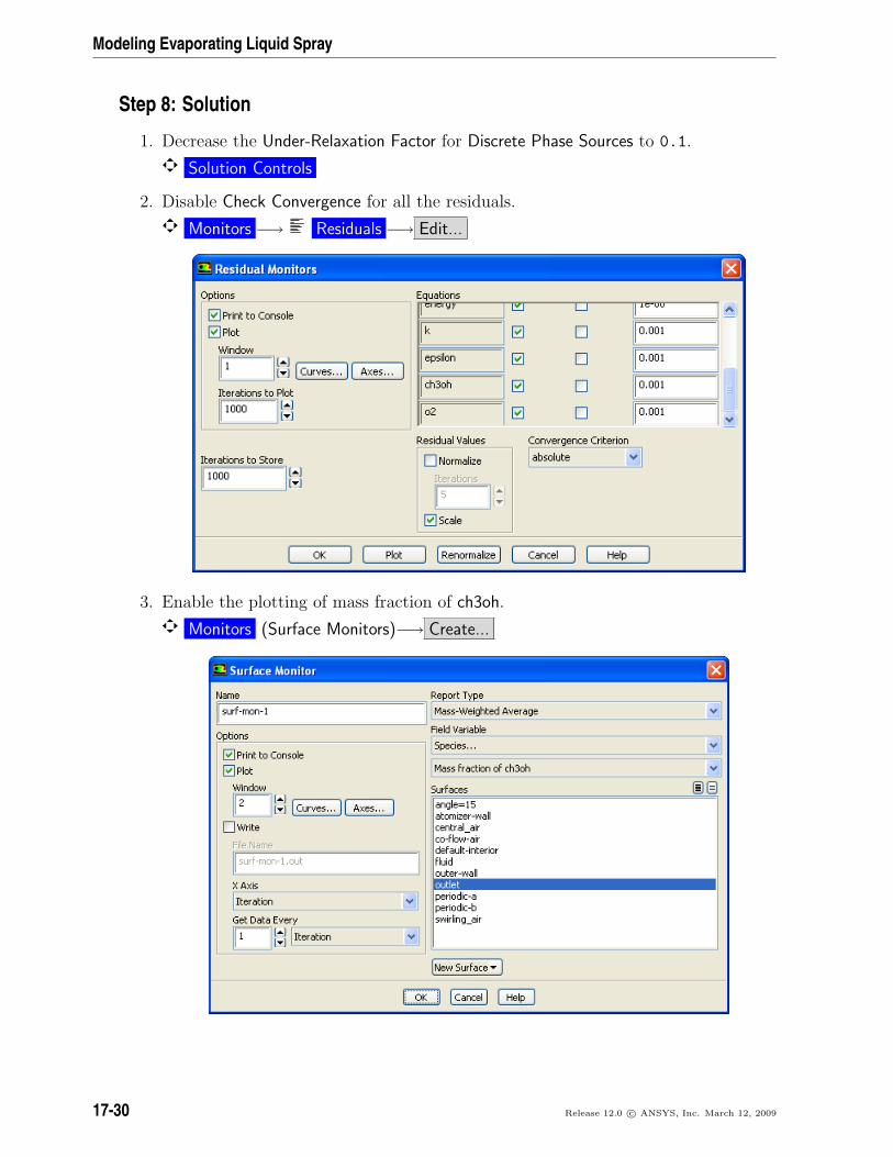
2. Disable Check Convergence for all the residuals.
Monitors −→ Residuals −→ Edit...
3. Enable the plotting of mass fraction of ch3oh.
Monitors (Surface Monitors)−→ Create...
17-30 Release 12.0 c© ANSYS, Inc. March 12, 2009
Modeling Evaporating Liquid Spray
(a) Retain surf-mon-1 for Name.
(b) Enable Plot.
(c) Select Mass-Weighted Average from the Report Type drop-down list.
(d) Select Species... and Mass fraction of ch3oh from the Field Variable drop-downlists.
(e) Select outlet from the Surfaces selection list.
(f) Click OK to close the Surface Monitor dialog box.
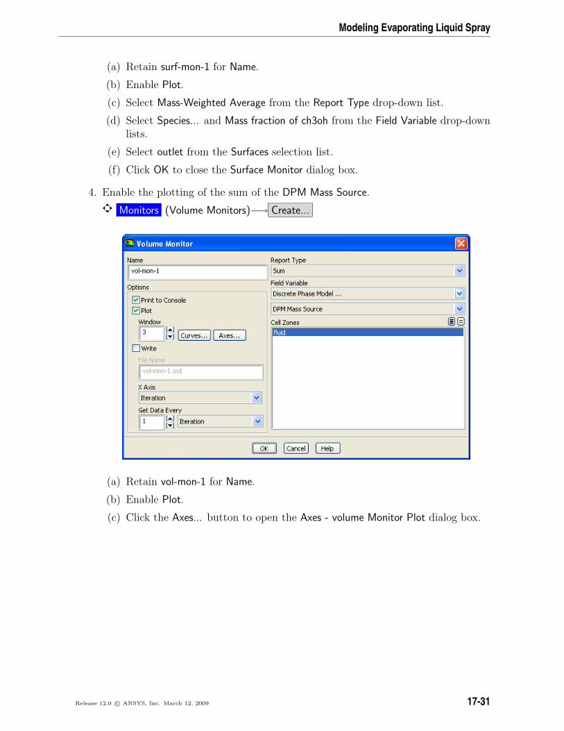
4. Enable the plotting of the sum of the DPM Mass Source.
Monitors (Volume Monitors)−→ Create...
(a) Retain vol-mon-1 for Name.
(b) Enable Plot.
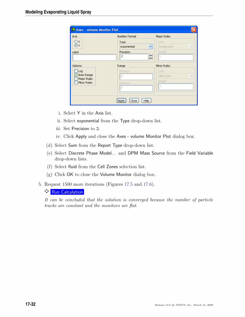
(c) Click the Axes... button to open the Axes - volume Monitor Plot dialog box.
Release 12.0 c© ANSYS, Inc. March 12, 2009 17-31
Modeling Evaporating Liquid Spray
i. Select Y in the Axis list.
ii. Select exponential from the Type drop-down list.
iii. Set Precision to 2.
iv. Click Apply and close the Axes - volume Monitor Plot dialog box.
(d) Select Sum from the Report Type drop-down list.
(e) Select Discrete Phase Model... and DPM Mass Source from the Field Variabledrop-down lists.
(f) Select fluid from the Cell Zones selection list.
(g) Click OK to close the Volume Monitor dialog box.
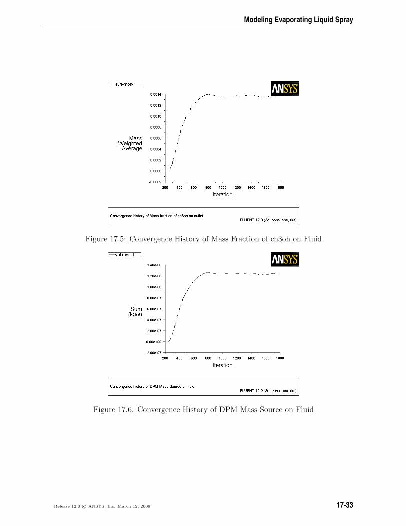
5. Request 1500 more iterations (Figures 17.5 and 17.6).
Run Calculation
It can be concluded that the solution is converged because the number of particletracks are constant and the monitors are flat.
17-32 Release 12.0 c© ANSYS, Inc. March 12, 2009
Modeling Evaporating Liquid Spray
Figure 17.5: Convergence History of Mass Fraction of ch3oh on Fluid
Figure 17.6: Convergence History of DPM Mass Source on Fluid
Release 12.0 c© ANSYS, Inc. March 12, 2009 17-33
Modeling Evaporating Liquid Spray
6. Save the case and data files (spray2.cas.gz and spray2.dat.gz).
File −→ Write −→Case & Data...
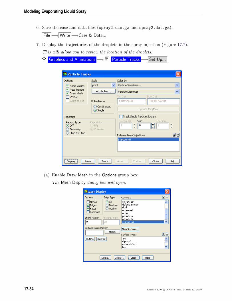
7. Display the trajectories of the droplets in the spray injection (Figure 17.7).
This will allow you to review the location of the droplets.
Graphics and Animations −→ Particle Tracks −→ Set Up...
(a) Enable Draw Mesh in the Options group box.
The Mesh Display dialog box will open.
17-34 Release 12.0 c© ANSYS, Inc. March 12, 2009
Modeling Evaporating Liquid Spray
i. Retain the current display settings.
ii. Close the Mesh Display dialog box.
(b) Retain the default selection of point from the Style drop-down list.
(c) Select Particle Variables... and Particle Diameter from the Color by drop-downlists.
This will display the location of the droplets colored by their diameters.
(d) Select injection-0 from the Release from Injections selection list.
(e) Click Display and close the Particle Tracks dialog box.
(f) Restore the 30–degree section to obtain the view as shown in Figure 17.7.
Graphics and Animations −→ Views...
i. Click the Define button to open Graphics Periodicity dialog box.
ii. Click Reset and close the Graphics Periodicity dialog box.
iii. Close the Views dialog box.
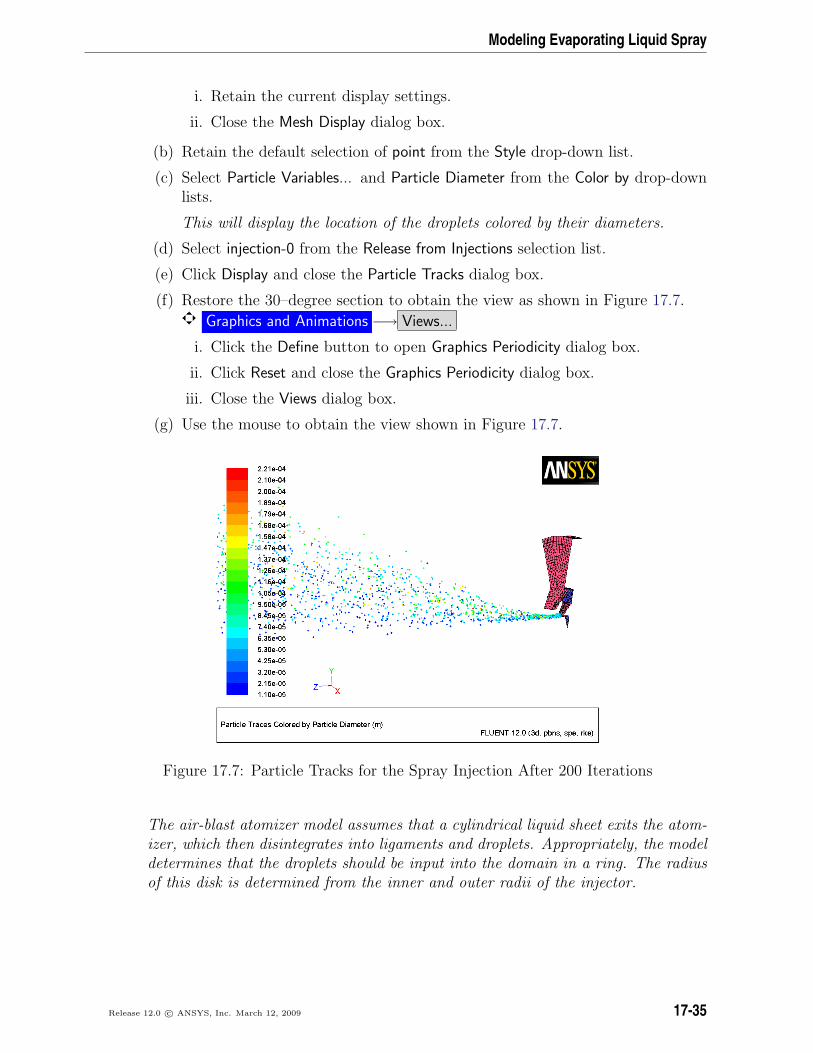
(g) Use the mouse to obtain the view shown in Figure 17.7.
Figure 17.7: Particle Tracks for the Spray Injection After 200 Iterations
The air-blast atomizer model assumes that a cylindrical liquid sheet exits the atom-izer, which then disintegrates into ligaments and droplets. Appropriately, the modeldetermines that the droplets should be input into the domain in a ring. The radiusof this disk is determined from the inner and outer radii of the injector.
Release 12.0 c© ANSYS, Inc. March 12, 2009 17-35
Modeling Evaporating Liquid Spray
Note: The maximum diameter of the droplets is about 10−4 m or 0.1 mm. This isslightly smaller than the film height. The inner diameter and outer diameterof the injector are 3.5 mm and 4.5 mm, respectively. Hence the film heightis 0.5 mm. The range in the droplet sizes is due to the fact that the air-blastatomizer automatically uses a distribution of droplet sizes.
Also note that the droplets are placed a slight distance away from the injector.Once the droplets are injected into the domain, they can collide/coalesce withother droplets as determined by the secondary models (breakup and collision).However, once a droplet has been introduced into the domain, the air-blastatomizer model no longer affects the droplet.
Step 9: Postprocessing
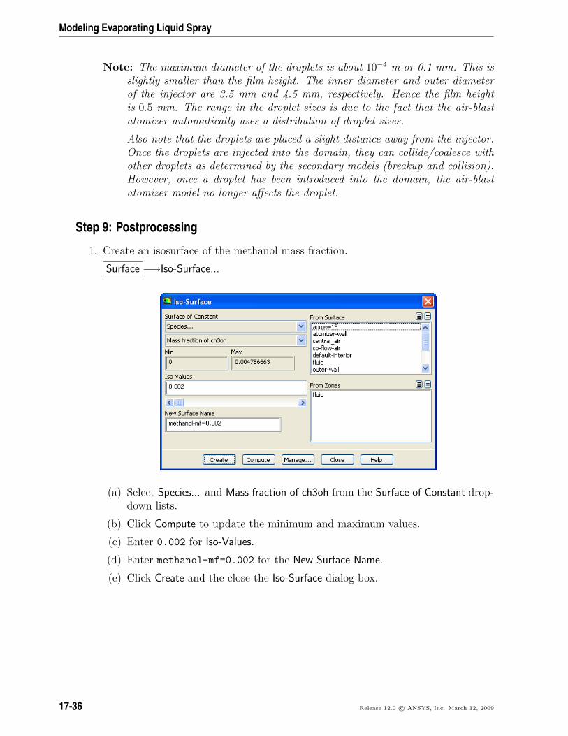
1. Create an isosurface of the methanol mass fraction.
Surface −→Iso-Surface...
(a) Select Species... and Mass fraction of ch3oh from the Surface of Constant drop-down lists.
(b) Click Compute to update the minimum and maximum values.
(c) Enter 0.002 for Iso-Values.
(d) Enter methanol-mf=0.002 for the New Surface Name.
(e) Click Create and the close the Iso-Surface dialog box.
17-36 Release 12.0 c© ANSYS, Inc. March 12, 2009
Modeling Evaporating Liquid Spray
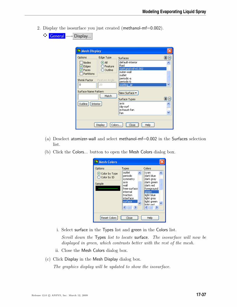
2. Display the isosurface you just created (methanol-mf=0.002).
General −→ Display...
(a) Deselect atomizer-wall and select methanol-mf=0.002 in the Surfaces selectionlist.
(b) Click the Colors... button to open the Mesh Colors dialog box.
i. Select surface in the Types list and green in the Colors list.
Scroll down the Types list to locate surface. The isosurface will now bedisplayed in green, which contrasts better with the rest of the mesh.
ii. Close the Mesh Colors dialog box.
(c) Click Display in the Mesh Display dialog box.
The graphics display will be updated to show the isosurface.
Release 12.0 c© ANSYS, Inc. March 12, 2009 17-37
Modeling Evaporating Liquid Spray
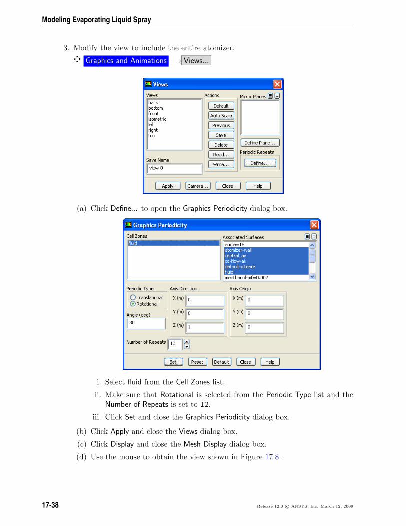
3. Modify the view to include the entire atomizer.
Graphics and Animations −→ Views...
(a) Click Define... to open the Graphics Periodicity dialog box.
i. Select fluid from the Cell Zones list.
ii. Make sure that Rotational is selected from the Periodic Type list and theNumber of Repeats is set to 12.
iii. Click Set and close the Graphics Periodicity dialog box.
(b) Click Apply and close the Views dialog box.
(c) Click Display and close the Mesh Display dialog box.
(d) Use the mouse to obtain the view shown in Figure 17.8.
17-38 Release 12.0 c© ANSYS, Inc. March 12, 2009

Modeling Evaporating Liquid Spray
Figure 17.8: Full Atomizer Display with Surface of Constant Methanol Mass Fraction
4. Save the case and data files (spray3.cas.gz and spray3.dat.gz).
File −→ Write −→Case & Data...
Summary
In this tutorial, a spray injection was defined for an air-blast atomizer and the solutionwas calculated using discrete-phase model in ANSYS FLUENT. The location of methanoldroplet particles after exiting the atomizer and an isosurface of the methanol mass frac-tion were examined.
Further Improvements
This tutorial guides you through the steps to reach an initial solution. You may be ableto obtain a more accurate solution by using an appropriate higher-order discretizationscheme and by adapting the mesh. Mesh adaption can also ensure that the solution isindependent of the mesh. These steps are demonstrated in Tutorial 1.
Release 12.0 c© ANSYS, Inc. March 12, 2009 17-39

Modeling Evaporating Liquid Spray
17-40 Release 12.0 c© ANSYS, Inc. March 12, 2009
Related Documents