TURCK Inc. 3000 Campus Drive Minneapolis, MN 55441 Application Support: 1-800-544-7769 Fax: (763) 553-0708 www.turck.com R2 Industrial Automation FOUNDATION fieldbus FOUNDATION ™ fieldbus Courtesy of Steven Engineering, Inc.-230 Ryan Way, South San Francisco, CA 94080-6370-Main Office: (650) 588-9200-Outside Local Area: (800) 258-9200-www.stevenengineering.com

Welcome message from author
This document is posted to help you gain knowledge. Please leave a comment to let me know what you think about it! Share it to your friends and learn new things together.
Transcript

TURCK Inc. 3000 Campus Drive Minneapolis, MN 55441 Application Support: 1-800-544-7769 Fax: (763) 553-0708 www.turck.com R2
IndustrialAutomation
FOU
ND
ATIO
Nfie
ldbu
s
FOUNDATION™ fieldbus
Courtesy of Steven Engineering, Inc.-230 Ryan Way, South San Francisco, CA 94080-6370-Main Office: (650) 588-9200-Outside Local Area: (800) 258-9200-www.stevenengineering.com
R3 TURCK Inc. 3000 Campus Drive Minneapolis, MN 55441 Application Support: 1-800-544-7769 Fax: (763) 553-0708 www.turck.com
TURCKNetwork Media Products
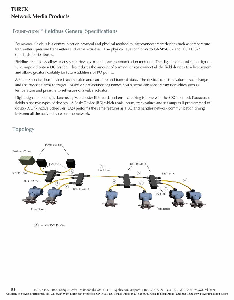
FOUNDATION™ fieldbus General Specifications
FOUNDATION fieldbus is a communication protocol and physical method to interconnect smart devices such as temperaturetransmitters, pressure transmitters and valve actuators. The physical layer conforms to ISA SP50.02 and IEC 1158-2standards for fieldbuses.
Fieldbus technology allows many smart devices to share one communication medium. The digital communication signal issuperimposed onto a DC carrier. This reduces the amount of terminations to connect all the field devices to a host systemand allows greater flexibility for future additions of I/O points.
A FOUNDATION fieldbus device is addressable and can store and transmit data. The devices can store values, track changesand use pre-set alarms to trigger. Based on pre-defined tag names host systems can read transmitter values such astemperature and pressure to set values of a valve actuator.
Digital signal encoding is done using Manchester BiPhase-L and error checking is done with the CRC method. FOUNDATION
fieldbus has two types of devices - A Basic Device (BD) which reads inputs, track values and set outputs if programmed todo so - A Link Active Scheduler (LAS) performs the same features as a BD and handles network communication timingbetween all the active devices on the network.
Topology
JBBS-49-M613
Fieldbus I/O host
Power Supplies
RKV 50-1M
RSV 490-1M
BRPC-49-M213A
Transmitters
= RSV RKV 490-1M
A
A
A
RSFK-BC
Trunk Line
Transmitters
RSV 49-TR
JBBS-49-M613A
A
A A
A
A
Courtesy of Steven Engineering, Inc.-230 Ryan Way, South San Francisco, CA 94080-6370-Main Office: (650) 588-9200-Outside Local Area: (800) 258-9200-www.stevenengineering.com
TURCK Inc. 3000 Campus Drive Minneapolis, MN 55441 Application Support: 1-800-544-7769 Fax: (763) 553-0708 www.turck.com R4
IndustrialAutomation
FOU
ND
ATIO
Nfie
ldbu
s
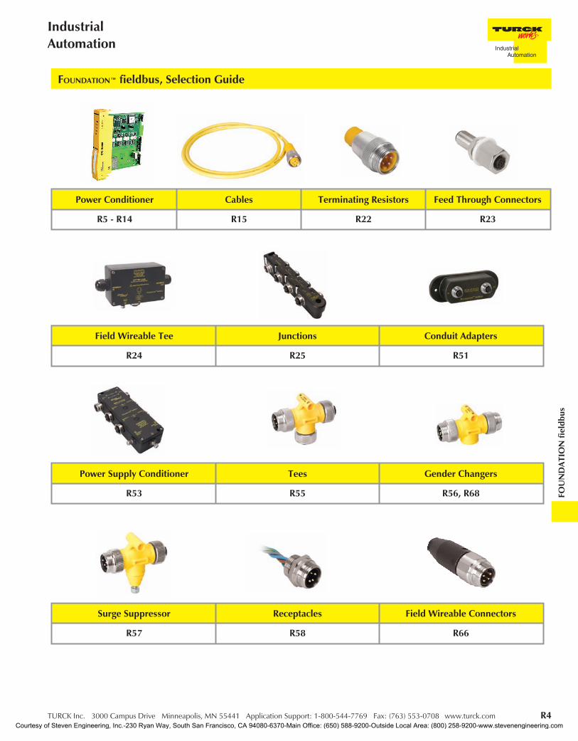
FOUNDATION™ fieldbus, Selection Guide
Field Wireable Tee Junctions Conduit Adapters
R24 R25 R51
Power Conditioner Cables Terminating Resistors Feed Through Connectors
R5 - R14 R15 R22 R23
Surge Suppressor Receptacles Field Wireable Connectors
R57 R58 R66
Power Supply Conditioner Tees Gender Changers
R53 R55 R56, R68
Courtesy of Steven Engineering, Inc.-230 Ryan Way, South San Francisco, CA 94080-6370-Main Office: (650) 588-9200-Outside Local Area: (800) 258-9200-www.stevenengineering.com
R5 TURCK Inc. 3000 Campus Drive Minneapolis, MN 55441 Application Support: 1-800-544-7769 Fax: (763) 553-0708 www.turck.com
TURCKNetwork Media Products
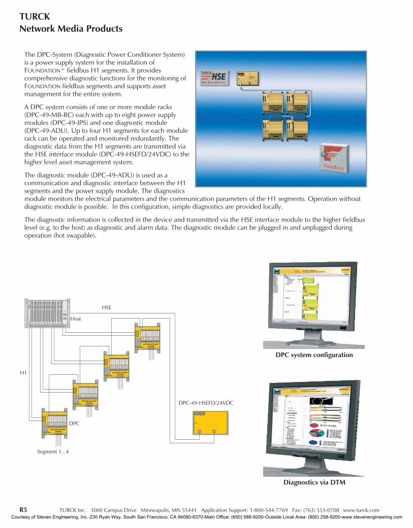
The DPC-System (Diagnostic Power Conditioner System)is a power supply system for the installation ofFOUNDATION™ fieldbus H1 segments. It providescomprehensive diagnostic functions for the monitoring ofFOUNDATION fieldbus segments and supports assetmanagement for the entire system.
A DPC system consists of one or more module racks(DPC-49-MB-RC) each with up to eight power supplymodules (DPC-49-IPS) and one diagnostic module(DPC-49-ADU). Up to four H1 segments for each modulerack can be operated and monitored redundantly. Thediagnostic data from the H1 segments are transmitted viathe HSE interface module (DPC-49-HSEFD/24VDC) to thehigher level asset management system.
The diagnostic module (DPC-49-ADU) is used as acommunication and diagnostic interface between the H1segments and the power supply module. The diagnosticsmodule monitors the electrical parameters and the communication parameters of the H1 segments. Operation withoutdiagnostic module is possible. In this configuration, simple diagnostics are provided locally.
The diagnostic information is collected in the device and transmitted via the HSE interface module to the higher fieldbuslevel (e.g. to the host) as diagnostic and alarm data. The diagnostic module can be plugged in and unplugged duringoperation (hot swapable).
Segment 1...4
DPC
H1
Host
HSE
DPC-49-HSEFD/24VDC
DPC system configuration
Diagnostics via DTM
Courtesy of Steven Engineering, Inc.-230 Ryan Way, South San Francisco, CA 94080-6370-Main Office: (650) 588-9200-Outside Local Area: (800) 258-9200-www.stevenengineering.com

TURCK Inc. 3000 Campus Drive Minneapolis, MN 55441 Application Support: 1-800-544-7769 Fax: (763) 553-0708 www.turck.com R6
IndustrialAutomation
FOU
ND
ATIO
Nfie
ldbu
s
Fieldbus - The dynamic assetInformation concerning the components of the control system and field devices are typically stored and monitored bythat system. Information on assets that make up the communication infrastructure (physical layer components) havebeen simply stored in an asset management system. With the DPC system, the physical layer components arecontinuously monitored providing virtually instantaneous information regarding the quality and the status of thecommunication link.This aspect of the system is the key to achieving the main objective of asset management to minimize maintenance andlower system operating costs.
TURCK has drastically improved on existing physical layer components for use in FOUNDATION™ fieldbus applications.The introduction of this system allows the continuous monitoring of every physical layer component, thus treating theentire physical layer as an asset and providing the means for it to be managed as such.
The DPC System detects errors that may develop over an extended period of time or through typical failure modes.These changes can occur due to many factors, such as environmental changes, deterioration of components over time,and any other factors that may affect the physical components of a fieldbus segment. Some of these factors may appearas changes in jitter, hum, noise levels etc. Alarm strategies may be employed that will warn of typical asset errors,potential errors or failures. Preventive measures can be implemented well in advance of a potential system failure.Most common failures can be completely avoided when a preventive maintenance schedule is implemented.The DPC system also supports the set-up of fieldbus assets by using expedient localization of error sources, as well asdocumentation indicating a "good condition" of the segment structure.
The DPC system provides an option for redundant segment supplies. The system, fully loaded, can accomodate up to16 fully redundant FOUNDATION fieldbus segments each with an output of 800 mA and 30 VDC. Diagnostic date isavailable via a DTM, standard FOUNDATION fieldbus function block libraries or an embedded web server in the HSE fielddevice.
Courtesy of Steven Engineering, Inc.-230 Ryan Way, South San Francisco, CA 94080-6370-Main Office: (650) 588-9200-Outside Local Area: (800) 258-9200-www.stevenengineering.com
R7 TURCK Inc. 3000 Campus Drive Minneapolis, MN 55441 Application Support: 1-800-544-7769 Fax: (763) 553-0708 www.turck.com
TURCKNetwork Media Products
The DPC-System (Diagnostic-Power-Conditioner-System) is a power supply system for the installation of FOUNDATION™ fieldbus H1segments. It offers comprehensive diagnostic functions for the monitoring of FOUNDATION™ fieldbus segments and thus supporting AssetManagement for the whole system.
A DPC system consists of one or more module racks DPC-49-MB-RC each with up to eight power supply modules DPC-49-IPS and onediagnostic module DPC-49-ADU. Up to four H1 segments for each module rack can be operated and monitored redundantly in theFOUNDATION™ fieldbus. The diagnostic data from the H1 segments are transmitted via the HSE interface module DPC-49-HSEFD/24VDC tothe higher level Asset-Management-System.
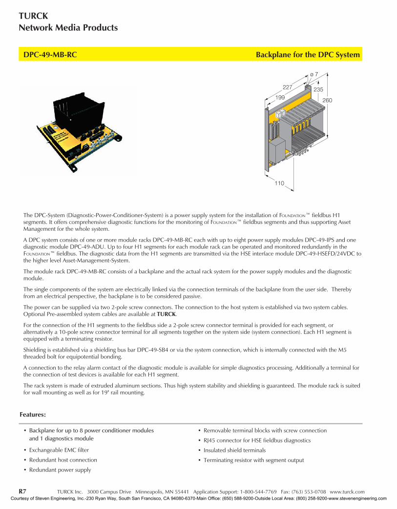
The module rack DPC-49-MB-RC consists of a backplane and the actual rack system for the power supply modules and the diagnosticmodule.
The single components of the system are electrically linked via the connection terminals of the backplane from the user side. Therebyfrom an electrical perspective, the backplane is to be considered passive.
The power can be supplied via two 2-pole screw connectors. The connection to the host system is established via two system cables.Optional Pre-assembled system cables are available at TURCK.
For the connection of the H1 segments to the fieldbus side a 2-pole screw connector terminal is provided for each segment, oralternatively a 10-pole screw connector terminal for all segments together on the system side (system connection). Each H1 segment isequipped with a terminating resistor.
Shielding is established via a shielding bus bar DPC-49-SB4 or via the system connection, which is internally connected with the M5threaded bolt for equipotential bonding.
A connection to the relay alarm contact of the diagnostic module is available for simple diagnostics processing. Additionally a terminal forthe connection of test devices is available for each H1 segment.
The rack system is made of extruded aluminum sections. Thus high system stability and shielding is guaranteed. The module rack is suitedfor wall mounting as well as for 19" rail mounting.
DPC-49-MB-RC Backplane for the DPC System
• Backplane for up to 8 power conditioner modulesand 1 diagnostics module
• Exchangeable EMC filter
• Redundant host connection
• Redundant power supply
• Removable terminal blocks with screw connection
• RJ45 connector for HSE fieldbus diagnostics
• Insulated shield terminals
• Terminating resistor with segment output
Features:
Courtesy of Steven Engineering, Inc.-230 Ryan Way, South San Francisco, CA 94080-6370-Main Office: (650) 588-9200-Outside Local Area: (800) 258-9200-www.stevenengineering.com

TURCK Inc. 3000 Campus Drive Minneapolis, MN 55441 Application Support: 1-800-544-7769 Fax: (763) 553-0708 www.turck.com R8
IndustrialAutomation
FOU
ND
ATIO
Nfie
ldbu
s
Backplane for the DPC System DPC-49-MB-RC
Part Number DPC-49-MB-RC
ID Number M6882010
Fieldbus Standard IEC 61158-2
Operating Voltage (Pwr) 18 to 32 VDC
Surge / Overvoltage Suppression < 250 mA
Connection Removable terminal block, reverse polarity protected, screw connection RJ45 socket
Protection Degree IP 20
Ambient Temperature -20 to +60°C (-4 to +140°F)
Housing Material Aluminum
Housing Color Black / Yellow
Dimensions 227 x 260 x 110 mm
Mounting Flush Panel
Installation Example:
Courtesy of Steven Engineering, Inc.-230 Ryan Way, South San Francisco, CA 94080-6370-Main Office: (650) 588-9200-Outside Local Area: (800) 258-9200-www.stevenengineering.com
R9 TURCK Inc. 3000 Campus Drive Minneapolis, MN 55441 Application Support: 1-800-544-7769 Fax: (763) 553-0708 www.turck.com
TURCKNetwork Media Products
The DPC-System (Diagnostic-Power-Conditioner-System) is a power supply system for the installation of Foundation fieldbus™H1segments. It offers comprehensive diagnostic functions for the monitoring of FOUNDATION™ fieldbus segments and thus supporting AssetManagement for the whole system.
A DPC system consists of one or more module racks DPC-49-MB-RC each with up to eight power supply modules DPC-49-IPS and onediagnostic module DPC-49-ADU. Up to four H1 segments for each module rack can be operated and monitored redundantly in theFOUNDATION™ fieldbus. The diagnostic data from the H1 segments are transmitted via the HSE interface module DPC-49-HSEFD/24VDCto the higher level Asset-Management-System.
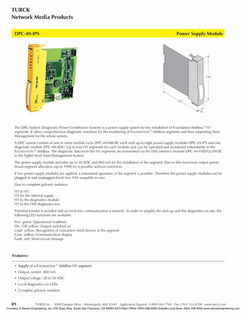
The power supply module provides up to 30 VDC and 800 mA for the installation of the segment. Due to this maximum output powerbroad segment allocation (up to 1900 m) is possible without restriction.
If two power supply modules are applied, a redundant operation of the segment is possible. Therefore the power supply modules can beplugged in and unplugged shock-free (Hot swapable in run).
Due to complete galvanic isolation:
H1 to H1H1 for the internal supplyH1 to the diagnostics moduleH1 to the HSE diagnostics bus
Potential transfer is avoided and an error-free communication is insured. In order to simplify the start-up and the diagnostics on site, thefollowing LED functions are available:
Pwr: green: Operational readinessOn / Off yellow: Output switched onLoad: yellow: Recognition of consumers (field device) at the segmentCom: yellow: Communication displayFault: red: Short-circuit message
DPC-49-IPS Power Supply Module
• Supply of a FOUNDATION™ fieldbus H1 segment
• Output current: 800 mA
• Output voltage: 28 to 30 VDC
• Local diagnostics via LEDs
• Complete galvanic isolation
Features:
Courtesy of Steven Engineering, Inc.-230 Ryan Way, South San Francisco, CA 94080-6370-Main Office: (650) 588-9200-Outside Local Area: (800) 258-9200-www.stevenengineering.com

TURCK Inc. 3000 Campus Drive Minneapolis, MN 55441 Application Support: 1-800-544-7769 Fax: (763) 553-0708 www.turck.com R10
IndustrialAutomation
FOU
ND
ATIO
Nfie
ldbu
s
Power Supply Module DPC-49-IPS
Part Number DPC-49-IPS
ID Number M6882013
Fieldbus Standard IEC 61158-2
Supply Voltage Via the backplane
Current Consumption 0.8 to 1.7 A
Galvanic Isolation Complete galvanic isolation, test voltage 500 VAC
Output Circuits Field
Output Current ≤ 800 mA
Output Voltage > 28 VDC
Short-circuit Protection ≤ 850 mA
Efficiency 80%
Output Circuits HOST
Output Current < 30 mA
Output Voltage < 27 VDC
Indication
Operational Readiness 1 x green
Output Active 1 x yellow
Output Current 1 x yellow
Short-circuit Message 1 x red
Bus Communication 1 x yellow
Protection Degree IP 20
Ambient Temperature -20 to +60°C (-4 to +140°F)
Housing Material Plastic / flammability class V-0 to UL 96
Housing Color Yellow
Dimensions 18 x 118 x 103 mm
Installation Example:
Courtesy of Steven Engineering, Inc.-230 Ryan Way, South San Francisco, CA 94080-6370-Main Office: (650) 588-9200-Outside Local Area: (800) 258-9200-www.stevenengineering.com
R11 TURCK Inc. 3000 Campus Drive Minneapolis, MN 55441 Application Support: 1-800-544-7769 Fax: (763) 553-0708 www.turck.com
TURCKNetwork Media Products
The DPC-System (Diagnostic-Power-Conditioner-System) is a power supply system for the installation of FOUNDATION fieldbus™ H1segments. It offers comprehensive diagnostic functions for the monitoring of FOUNDATION fieldbus™ segments and thus supporting AssetManagement for the whole system.
A DPC system consists of one or more module racks DPC-49-MB-RC each with up to eight power supply modules DPC-49-IPS and onediagnostic module DPC-49-ADU. Up to four H1 segments for each module rack can be operated and monitored redundantly in theFOUNDATION fieldbus™. The diagnostic data from the H1 segments are transmitted via the HSE interface moduleDPC-49-HSEFD/24VDC to the higher level Asset-Management-System.
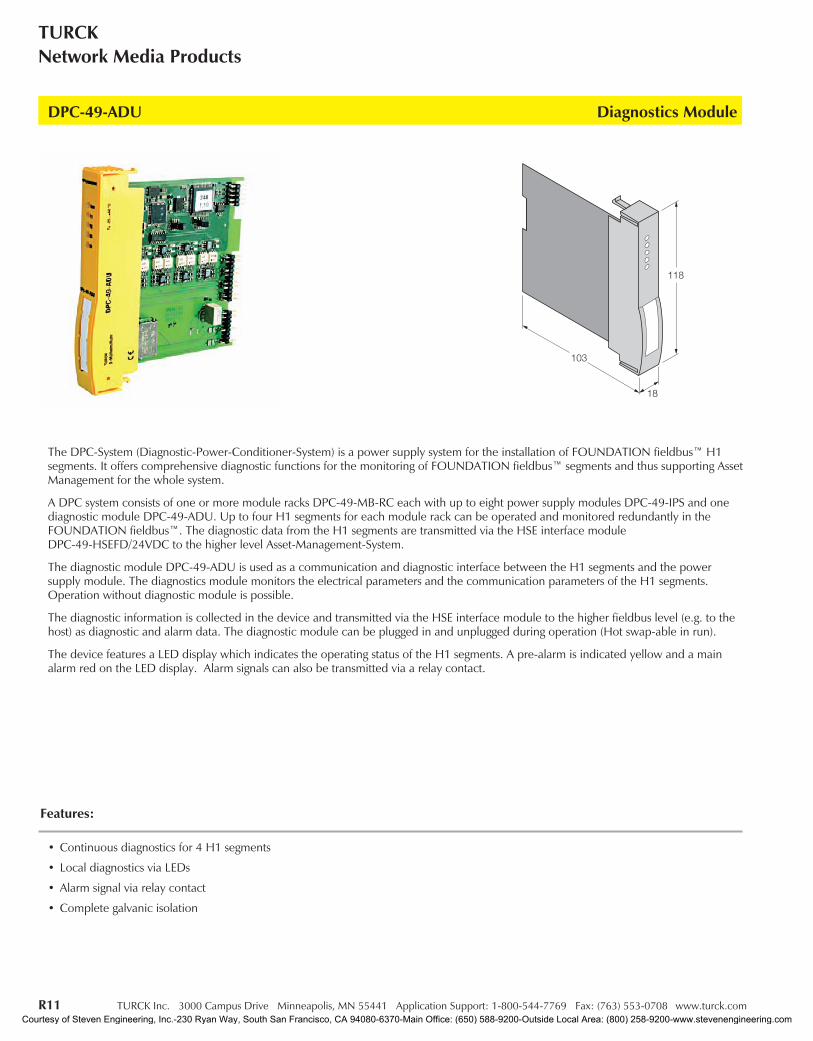
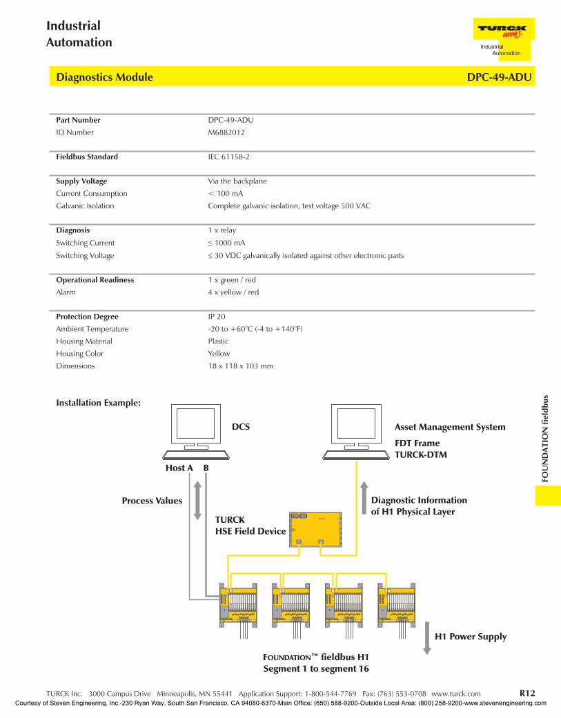
The diagnostic module DPC-49-ADU is used as a communication and diagnostic interface between the H1 segments and the powersupply module. The diagnostics module monitors the electrical parameters and the communication parameters of the H1 segments.Operation without diagnostic module is possible.
The diagnostic information is collected in the device and transmitted via the HSE interface module to the higher fieldbus level (e.g. to thehost) as diagnostic and alarm data. The diagnostic module can be plugged in and unplugged during operation (Hot swap-able in run).
The device features a LED display which indicates the operating status of the H1 segments. A pre-alarm is indicated yellow and a mainalarm red on the LED display. Alarm signals can also be transmitted via a relay contact.
DPC-49-ADU Diagnostics Module
• Continuous diagnostics for 4 H1 segments
• Local diagnostics via LEDs
• Alarm signal via relay contact
• Complete galvanic isolation
Features:
Courtesy of Steven Engineering, Inc.-230 Ryan Way, South San Francisco, CA 94080-6370-Main Office: (650) 588-9200-Outside Local Area: (800) 258-9200-www.stevenengineering.com
TURCK Inc. 3000 Campus Drive Minneapolis, MN 55441 Application Support: 1-800-544-7769 Fax: (763) 553-0708 www.turck.com R12
IndustrialAutomation
FOU
ND
ATIO
Nfie
ldbu
s
Diagnostics Module DPC-49-ADU
Part Number DPC-49-ADU
ID Number M6882012
Fieldbus Standard IEC 61158-2
Supply Voltage Via the backplane
Current Consumption < 100 mA
Galvanic Isolation Complete galvanic isolation, test voltage 500 VAC
Diagnosis 1 x relay
Switching Current ≤ 1000 mA
Switching Voltage ≤ 30 VDC galvanically isolated against other electronic parts
Operational Readiness 1 x green / red
Alarm 4 x yellow / red
Protection Degree IP 20
Ambient Temperature -20 to +60°C (-4 to +140°F)
Housing Material Plastic
Housing Color Yellow
Dimensions 18 x 118 x 103 mm
Installation Example:
Courtesy of Steven Engineering, Inc.-230 Ryan Way, South San Francisco, CA 94080-6370-Main Office: (650) 588-9200-Outside Local Area: (800) 258-9200-www.stevenengineering.com

R13 TURCK Inc. 3000 Campus Drive Minneapolis, MN 55441 Application Support: 1-800-544-7769 Fax: (763) 553-0708 www.turck.com
TURCKNetwork Media Products
The DPC-System (Diagnostic-Power-Conditioner-System) is a power supply system for the installation of Foundation fieldbus™ H1segments. It offers comprehensive diagnostic functions for the monitoring of FOUNDATION™ fieldbus segments thus supporting AssetManagement for the whole system.
A DPC system consists of one or more module racks DPC-49-MB-RC, each with up to eight power supply modules DPC-49-IPS and onediagnostic module DPC-49-ADU. Up to four H1 segments for each module rack can be operated and monitored redundantly in theFOUNDATION™ fieldbus.
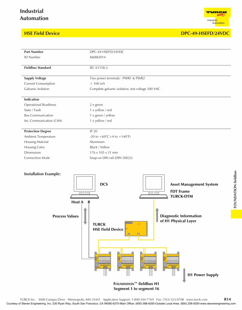
The diagnostic data from the H1 segments are transmitted via the HSE interface module DPC-49-HSEFD/24VDC to the higher levelAsset-Management-System. Only the diagnostics data of the diagnostic module DPC-49-ADU are transmitted with the HSE interfacemodule, not the process data of the H1 field device. Each diagnostic module monitors up to four H1 segments.
The HSE interface module is a FOUNDATION™ fieldbus field device, which contains one resource and one transducer block and variousstandard function blocks. On the basis of these standard function blocks, suitable applications for the analysis of the diagnostics data canbe programmed in the control system.
DPC-49-HSEFD/24VDC HSE Field Device
• HSE interface module for the transmission of diagnostic data
• FOUNDATION™ fieldbus function blocks for remote diagnostics
• Diagnostics via LEDs
• Continuous diagnostics for sixteen H1 segments
• Complete galvanic isolation
• Complete galvanic isolation
Features:
Courtesy of Steven Engineering, Inc.-230 Ryan Way, South San Francisco, CA 94080-6370-Main Office: (650) 588-9200-Outside Local Area: (800) 258-9200-www.stevenengineering.com
TURCK Inc. 3000 Campus Drive Minneapolis, MN 55441 Application Support: 1-800-544-7769 Fax: (763) 553-0708 www.turck.com R14
IndustrialAutomation
FOU
ND
ATIO
Nfie
ldbu
s
HSE Field Device DPC-49-HSEFD/24VDC
Part Number DPC-49-HSEFD/24VDC
ID Number M6882014
Fieldbus Standard IEC 61158-2
Supply Voltage Two power terminals - PWR1 & PWR2
Current Consumption < 100 mA
Galvanic Isolation Complete galvanic isolation, test voltage 500 VAC
Indication
Operational Readiness 2 x green
State / Fault 1 x yellow / red
Bus Communication 1 x green / yellow
Int. Communication (CAN) 1 x yellow / red
Protection Degree IP 20
Ambient Temperature -20 to +60°C (-4 to +140°F)
Housing Material Aluminum
Housing Color Black / Yellow
Dimensions 176 x 105 x 31 mm
Connection Mode Snap-on DIN rail (DIN 50022)
Installation Example:
Courtesy of Steven Engineering, Inc.-230 Ryan Way, South San Francisco, CA 94080-6370-Main Office: (650) 588-9200-Outside Local Area: (800) 258-9200-www.stevenengineering.com
R15 TURCK Inc. 3000 Campus Drive Minneapolis, MN 55441 Application Support: 1-800-544-7769 Fax: (763) 553-0708 www.turck.com
TURCKNetwork Media Products
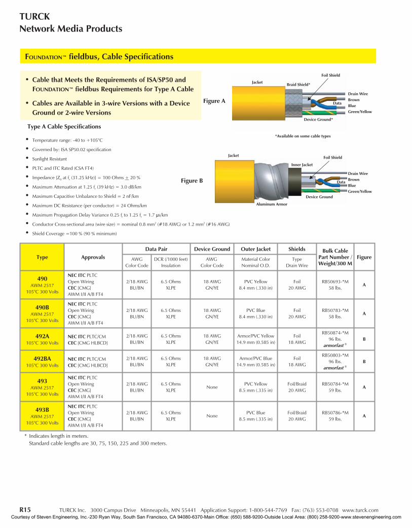
• Cable that Meets the Requirements of ISA/SP50 andFOUNDATION™ fieldbus Requirements for Type A Cable
• Cables are Available in 3-wire Versions with a DeviceGround or 2-wire Versions
FOUNDATION™ fieldbus, Cable Specifications
Type ApprovalsData Pair Device Ground Outer Jacket Shields Bulk Cable
Part Number /Weight/300 M
FigureAWGColor Code
DCR (/1000 feet)Insulation
AWGColor Code
Material ColorNominal O.D.
TypeDrain Wire
490AWM 2517
105°C 300 Volts
NEC ITC PLTCOpen WiringCEC [CMG]AWM I/II A/B FT4
2/18 AWGBU/BN
6.5 OhmsXLPE
18 AWGGN/YE
PVC Yellow8.4 mm (.330 in)
Foil20 AWG
RB50693-*M58 lbs.
A
490BAWM 2517
105°C 300 Volts
NEC ITC PLTCOpen WiringCEC [CMG]AWM I/II A/B FT4
2/18 AWGBU/BN
6.5 OhmsXLPE
18 AWGGN/YE
PVC Blue8.4 mm (.330 in)
Foil20 AWG
RB50783-*M58 lbs.
A
492A105°C 300 Volts
NEC ITC PLTC/CMCEC [CMG HLBCD]
2/18 AWGBU/BN
6.5 OhmsXLPE
18 AWGGN/YE
Armor/PVC Yellow14.9 mm (0.585 in)
Foil18 AWG
RB50874-*M96 lbs.
armorfast ®
B
492BA105°C 300 Volts
NEC ITC PLTC/CMCEC [CMG HLBCD]
2/18 AWGBU/BN
6.5 OhmsXLPE
18 AWGGN/YE
Armor/PVC Blue14.9 mm (0.585 in)
Foil18 AWG
RB50803-*M96 lbs.
armorfast ®
B
493AWM 2517
105°C 300 Volts
NEC ITC PLTCOpen WiringCEC [CMG]AWM I/II A/B FT4
2/18 AWGBU/BN
6.5 OhmsXLPE
NonePVC Yellow
8.5 mm (.335 in)Foil/Braid20 AWG
RB50784-*M59 lbs.
A
493BAWM 2517
105°C 300 Volts
NEC ITC PLTCOpen WiringCEC [CMG]AWM I/II A/B FT4
2/18 AWGBU/BN
6.5 OhmsXLPE
NonePVC Blue
8.5 mm (.335 in)Foil/Braid20 AWG
RB50786-*M59 lbs.
A
* Indicates length in meters.Standard cable lengths are 30, 75, 150, 225 and 300 meters.
Drain WireBrownBlueGreen/Yellow
Figure A
Figure BDrain WireBrownBlueGreen/Yellow
Jacket
Data
Device Ground
Inner Jacket
Aluminum Armor
Jacket
Data
*Available on some cable types
Device Ground*
Foil Shield
Braid Shield*
Foil Shield
Type A Cable Specifications
• Temperature range: -40 to +105°C
• Governed by: ISA SP50.02 specification
• Sunlight Resistant
• PLTC and ITC Rated (CSA FT4)
• Impedance [Z0 at fr (31.25 kHz)] = 100 Ohms + 20 %
• Maximum Attenuation at 1.25 fr (39 kHz) = 3.0 dB/km
• Maximum Capacitive Unbalance to Shield = 2 nF/km
• Maximum DC Resistance (per conductor) = 24 Ohms/km
• Maximum Propagation Delay Variance 0.25 fr to 1.25 fr = 1.7 µs/km
• Conductor Cross-sectional area (wire size) = nominal 0.8 mm2 (#18 AWG) or 1.2 mm2 (#16 AWG)
• Shield Coverage =100 % (90 % minimum)
Courtesy of Steven Engineering, Inc.-230 Ryan Way, South San Francisco, CA 94080-6370-Main Office: (650) 588-9200-Outside Local Area: (800) 258-9200-www.stevenengineering.com
TURCK Inc. 3000 Campus Drive Minneapolis, MN 55441 Application Support: 1-800-544-7769 Fax: (763) 553-0708 www.turck.com R16
IndustrialAutomation
FOU
ND
ATIO
Nfie
ldbu
s
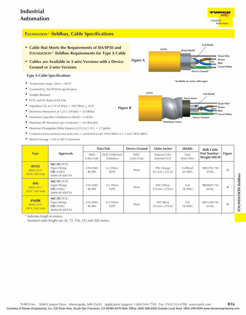
• Cable that Meets the Requirements of ISA/SP50 andFOUNDATION™ fieldbus Requirements for Type A Cable
• Cables are Available in 3-wire Versions with a DeviceGround or 2-wire Versions
FOUNDATION™ fieldbus, Cable Specifications
Type ApprovalsData Pair Device Ground Outer Jacket Shields Bulk Cable
Part Number /Weight/300 M
FigureAWGColor Code
DCR (/1000 feet)Insulation
AWGColor Code
Material ColorNominal O.D.
TypeDrain Wire
493OAWM 2517
105°C 300 Volts
NEC ITC PLTCOpen WiringCEC [CMG]AWM I/II A/B FT4
2/18 AWGBU/BN
6.5 OhmsXLPE
NonePVC Orange
8.5 mm (.335 in)Foil/Braid20 AWG
RB50785-*M59 lbs.
A
496AWM 2517
105°C 300 Volts
NEC ITC PLTCOpen WiringCEC [CMG]AWM I/II A/B FT4
2/16 AWGBU/BN
4.1 OhmsXLPE
NonePVC Yellow
9.6 mm (.378 in)Foil
18 AWGRB50891-*M
64 lbs.A
496BKAWM 2517
105°C 300 Volts
NEC ITC PLTCOpen WiringCEC [CMG]AWM I/II A/B FT4
2/16 AWGBU/BN
4.1 OhmsXLPE
NonePVC Black
9.6 mm (.378 in)Foil
18 AWGRB51300-*M
64 lbs.A
* Indicates length in meters.Standard cable lengths are 30, 75, 150, 225 and 300 meters.
Drain WireBrownBlueGreen/Yellow
Figure A
Figure BDrain WireBrownBlueGreen/Yellow
Jacket
Data
Device Ground
Inner Jacket
Aluminum Armor
Jacket
Data
*Available on some cable types
Device Ground*
Foil Shield
Braid Shield*
Foil Shield
Type A Cable Specifications
• Temperature range: -40 to +105°C
• Governed by: ISA SP50.02 specification
• Sunlight Resistant
• PLTC and ITC Rated (CSA FT4)
• Impedance [Z0 at fr (31.25 kHz)] = 100 Ohms + 20 %
• Maximum Attenuation at 1.25 fr (39 kHz) = 3.0 dB/km
• Maximum Capacitive Unbalance to Shield = 2 nF/km
• Maximum DC Resistance (per conductor) = 24 Ohms/km
• Maximum Propagation Delay Variance 0.25 fr to 1.25 fr = 1.7 µs/km
• Conductor Cross-sectional area (wire size) = nominal 0.8 mm2 (#18 AWG) or 1.2 mm2 (#16 AWG)
• Shield Coverage =100 % (90 % minimum)
Courtesy of Steven Engineering, Inc.-230 Ryan Way, South San Francisco, CA 94080-6370-Main Office: (650) 588-9200-Outside Local Area: (800) 258-9200-www.stevenengineering.com
R17 TURCK Inc. 3000 Campus Drive Minneapolis, MN 55441 Application Support: 1-800-544-7769 Fax: (763) 553-0708 www.turck.com
TURCKNetwork Media Products
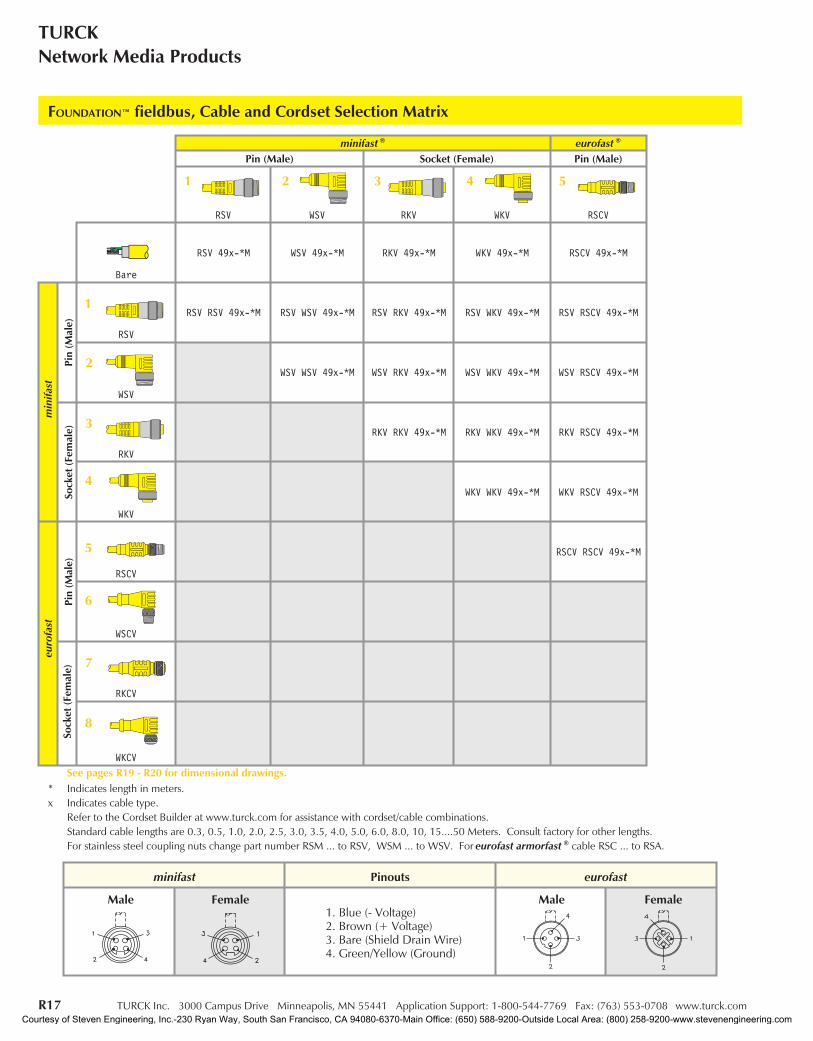
FOUNDATION™ fieldbus, Cable and Cordset Selection Matrix
1 2 543
1
2
3
4
5
6
7
8
minifast Pinouts eurofast
1. Blue (- Voltage)2. Brown (+ Voltage)3. Bare (Shield Drain Wire)4. Green/Yellow (Ground)
minifast ® eurofast ®
Pin (Male) Socket (Female) Pin (Male)
RSV WSV RKV WKV RSCV
Bare
RSV 49x-*M WSV 49x-*M RKV 49x-*M WKV 49x-*M RSCV 49x-*M
min
ifast
Pin
(Mal
e)
RSV
RSV RSV 49x-*M RSV WSV 49x-*M RSV RKV 49x-*M RSV WKV 49x-*M RSV RSCV 49x-*M
WSV
WSV WSV 49x-*M WSV RKV 49x-*M WSV WKV 49x-*M WSV RSCV 49x-*M
Sock
et(F
emal
e)
RKV
RKV RKV 49x-*M RKV WKV 49x-*M RKV RSCV 49x-*M
WKV
WKV WKV 49x-*M WKV RSCV 49x-*M
euro
fast
Pin
(Mal
e)
RSCV
RSCV RSCV 49x-*M
WSCV
Sock
et(F
emal
e)
RKCV
WKCVSee pages R19 - R20 for dimensional drawings.
* Indicates length in meters.x Indicates cable type.
Refer to the Cordset Builder at www.turck.com for assistance with cordset/cable combinations.Standard cable lengths are 0.3, 0.5, 1.0, 2.0, 2.5, 3.0, 3.5, 4.0, 5.0, 6.0, 8.0, 10, 15....50 Meters. Consult factory for other lengths.For stainless steel coupling nuts change part number RSM ... to RSV, WSM ... to WSV. For eurofast armorfast ® cable RSC ... to RSA.
Male Female Male Female
Courtesy of Steven Engineering, Inc.-230 Ryan Way, South San Francisco, CA 94080-6370-Main Office: (650) 588-9200-Outside Local Area: (800) 258-9200-www.stevenengineering.com

TURCK Inc. 3000 Campus Drive Minneapolis, MN 55441 Application Support: 1-800-544-7769 Fax: (763) 553-0708 www.turck.com R18
IndustrialAutomation
FOU
ND
ATIO
Nfie
ldbu
s
FOUNDATION™ fieldbus, Cable and Cordset Selection Matrix
eurofast ® minifast ® Bulkhead eurofast BulkheadPin (Male) Socket (Female) Pin (Male) Socket (Female) Pin (Male) Socket (Female)
WSCV RKCV WKCV RSFPV RKFPV FSFDV FKFDV
WSCV 49x-*M RKCV 49x-*M WKCV 49x-*M RSFPV 49x-*M RKFPV 49x-*M FSFDV 49x-*M FKFDV 49x-*M
RSV WSCV 49x-*M RSV RKCV 49x-*M RSV WKCV 49x-*M RSV RSFPV 49x-*M RSV RKFPV 49x-*M RSV FSFDV 49x-*M RSV FKFDV 49x-*M
WSV WSCV 49x-*M WSV RKCV 49x-*M WSV WKCV 49x-*M WSV RSFPV 49x-*M WSV RKFPV 49x-*M WSV FSFDV 49x-*M WSV FKFDV 49x-*M
RKV WSCV 49x-*M RKV RKCV 49x-*M RKV WKCV 49x-*M RKV RSFPV 49x-*M RKV RKFPV 49x-*M RKV FSFDV 49x-*M RKV FKFDV 49x-*M
WKV WSCV 49x-*M WKV RKCV 49x-*M WKV WKCV 49x-*M WKV RSFPV 49x-*M WKV RKFPV 49x-*M WKV FSFDV 49-*M WKV FKFDV 49x-*M
RSCV WSCV 49x-*M RSCV RKCV 49x-*M RSCV WKCV 49x-*M RSCV RSFPV 49x-*M RSCV RKFPV 49x-*M RSCV FSFDV 49x-*M RSCV FKFDV 49x-*M
WSCV WSCV 49x-*M WSCV RKCV 49x-*M WSCV WKCV 49x-*M WSCV RSFPV 49x-*M WSCV RKFPV 49x-*M WSCV FSFDV 49x-*M WSCV FKFDV 49x-*M
RKCV RKCV 49x-*M RKCV WKCV 49x-*M RKCV RSFPV 49x-*M RKCV RKFPV 49x-*M RKCV FSFDV 49x-*M RKCV FKFDV 49x-*M
WKCV WKCV 49x-*M WKCV RSFPV 49x-*M WKCV RKFPV 49x-*M WKCV FSFDV 49x-*M WKCV FKFDV 49x-*M
6 7 8 9 10 11 12
Courtesy of Steven Engineering, Inc.-230 Ryan Way, South San Francisco, CA 94080-6370-Main Office: (650) 588-9200-Outside Local Area: (800) 258-9200-www.stevenengineering.com

R19 TURCK Inc. 3000 Campus Drive Minneapolis, MN 55441 Application Support: 1-800-544-7769 Fax: (763) 553-0708 www.turck.com
TURCKNetwork Media Products
3
RKV .. Pages R17 - R18
4
WKV .. Pages R17 - R18
10
RKFPV .. Pages R17 - R18
FOUNDATION™ fieldbus, minifast ® Cordset and Receptacle Connector Dimensions
1
RSV .. Pages R17 - R18
2
WSV .. Pages R17 - R18
9
RSFPV .. Pages R17 - R18
Housing: PUR (Polyurethane)Coupling Nut: Nickel Plated CuZn or Stainless SteelContact Carrier: TPU (Polyurethane)Contacts: Gold Plated CuZnProtection: NEMA 1, 3, 4, 6P and IEC IP 68Rated Voltage: 300 VRated Current: 9 AAmbient Temperature: -40° to +105°C (-40° to +221°F)
Specifications
Courtesy of Steven Engineering, Inc.-230 Ryan Way, South San Francisco, CA 94080-6370-Main Office: (650) 588-9200-Outside Local Area: (800) 258-9200-www.stevenengineering.com
TURCK Inc. 3000 Campus Drive Minneapolis, MN 55441 Application Support: 1-800-544-7769 Fax: (763) 553-0708 www.turck.com R20
IndustrialAutomation
FOU
ND
ATIO
Nfie
ldbu
s
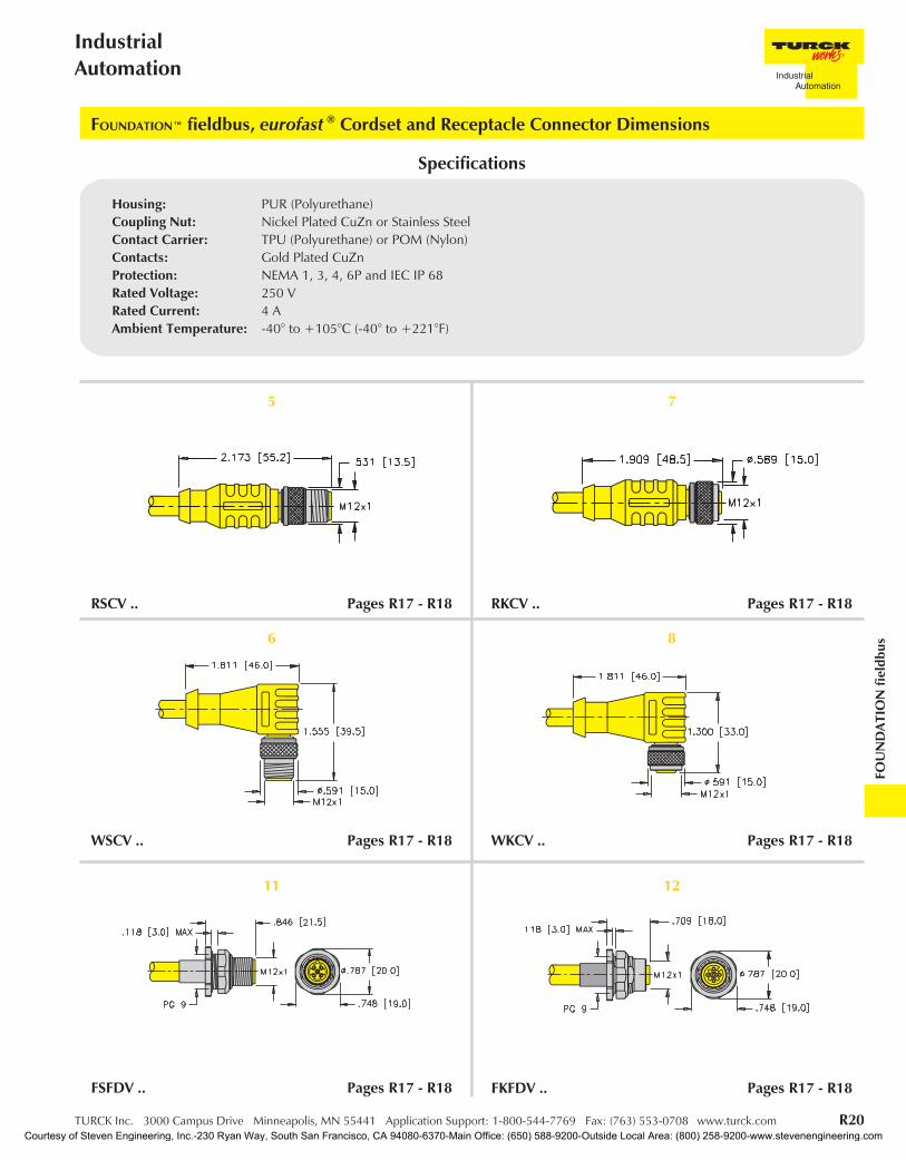
5
RSCV .. Pages R17 - R18
6
WSCV .. Pages R17 - R18
11
FSFDV .. Pages R17 - R18
FOUNDATION™ fieldbus, eurofast ® Cordset and Receptacle Connector Dimensions
7
RKCV .. Pages R17 - R18
8
WKCV .. Pages R17 - R18
12
FKFDV .. Pages R17 - R18
Housing: PUR (Polyurethane)Coupling Nut: Nickel Plated CuZn or Stainless SteelContact Carrier: TPU (Polyurethane) or POM (Nylon)Contacts: Gold Plated CuZnProtection: NEMA 1, 3, 4, 6P and IEC IP 68Rated Voltage: 250 VRated Current: 4 AAmbient Temperature: -40° to +105°C (-40° to +221°F)
Specifications
Courtesy of Steven Engineering, Inc.-230 Ryan Way, South San Francisco, CA 94080-6370-Main Office: (650) 588-9200-Outside Local Area: (800) 258-9200-www.stevenengineering.com
R21 TURCK Inc. 3000 Campus Drive Minneapolis, MN 55441 Application Support: 1-800-544-7769 Fax: (763) 553-0708 www.turck.com
TURCKNetwork Media Products
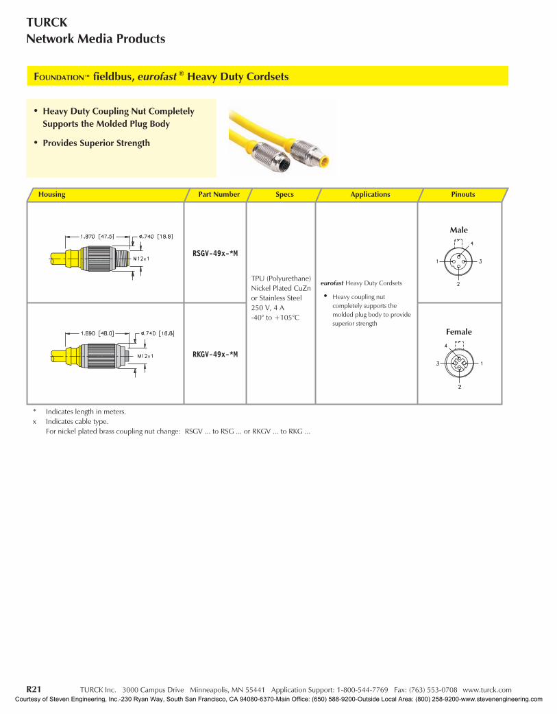
FOUNDATION™ fieldbus, eurofast ® Heavy Duty Cordsets
Housing Part Number Specs Applications Pinouts
RSGV-49x-*M
TPU (Polyurethane)Nickel Plated CuZnor Stainless Steel250 V, 4 A-40° to +105°C
eurofast Heavy Duty Cordsets
• Heavy coupling nutcompletely supports themolded plug body to providesuperior strength
RKGV-49x-*M
* Indicates length in meters.x Indicates cable type.
For nickel plated brass coupling nut change: RSGV ... to RSG ... or RKGV ... to RKG ...
Male
Female
• Heavy Duty Coupling Nut CompletelySupports the Molded Plug Body
• Provides Superior Strength
Courtesy of Steven Engineering, Inc.-230 Ryan Way, South San Francisco, CA 94080-6370-Main Office: (650) 588-9200-Outside Local Area: (800) 258-9200-www.stevenengineering.com

TURCK Inc. 3000 Campus Drive Minneapolis, MN 55441 Application Support: 1-800-544-7769 Fax: (763) 553-0708 www.turck.com R22
IndustrialAutomation
FOU
ND
ATIO
Nfie
ldbu
s
FOUNDATION™ fieldbus, Terminating Resistors
Housing Part Number Specs Application Pinouts
RSV 49-TR
Nickel Plated Brass orStainless Steel250 V, 4 A-40° to +75°C
minifast ® Terminating Resistor
• Male minifast connector
RSEV 49-TReurofast ® Terminating Resistor
• Male eurofast connector
Male
Male
• Terminating Resistors Stabilize andMinimize Reflections on the Bus Line
• A Terminating Resistor is Required at theBeginning and End of the Main Bus Line
Courtesy of Steven Engineering, Inc.-230 Ryan Way, South San Francisco, CA 94080-6370-Main Office: (650) 588-9200-Outside Local Area: (800) 258-9200-www.stevenengineering.com
R23 TURCK Inc. 3000 Campus Drive Minneapolis, MN 55441 Application Support: 1-800-544-7769 Fax: (763) 553-0708 www.turck.com
TURCKNetwork Media Products
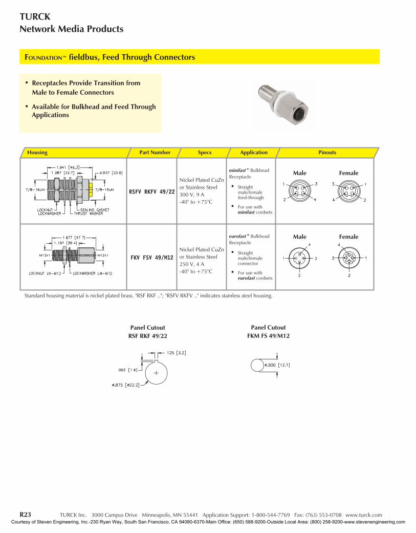
FOUNDATION™ fieldbus, Feed Through Connectors
Housing Part Number Specs Application Pinouts
RSFV RKFV 49/22
Nickel Plated CuZnor Stainless Steel300 V, 9 A-40° to +75°C
minifast ® BulkheadReceptacle
• Straightmale/femalefeed-through
• For use withminifast cordsets
FKV FSV 49/M12Nickel Plated CuZnor Stainless Steel250 V, 4 A-40° to +75°C
eurofast ® BulkheadReceptacle
• Straightmale/femaleconnector
• For use witheurofast cordsets
Standard housing material is nickel plated brass. "RSF RKF .."; "RSFV RKFV .." indicates stainless steel housing.
Female
Male Female
Male
• Receptacles Provide Transition fromMale to Female Connectors
• Available for Bulkhead and Feed ThroughApplications
Panel CutoutFKM FS 49/M12
Panel CutoutRSF RKF 49/22
Courtesy of Steven Engineering, Inc.-230 Ryan Way, South San Francisco, CA 94080-6370-Main Office: (650) 588-9200-Outside Local Area: (800) 258-9200-www.stevenengineering.com
TURCK Inc. 3000 Campus Drive Minneapolis, MN 55441 Application Support: 1-800-544-7769 Fax: (763) 553-0708 www.turck.com R24
IndustrialAutomation
FOU
ND
ATIO
Nfie
ldbu
s
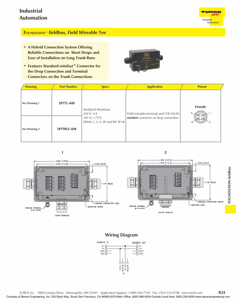
FOUNDATION™ fieldbus, Field Wireable Tee
Housing Part Number Specs Application Pinout
See Drawing 1 SPTT1-A49
Anodized Aluminum250 V, 4 A-40° to +75°CNEMA 1, 3, 4, 6P and IEC IP 68
Field wireable terminals and (7/8-16UN)minifast connector on drop connection
See Drawing 2 SPTTM13-A49
Female
1 2
• A Hybrid Connection System OfferingReliable Connections on Short Drops andEase of Installation on Long Trunk Runs
• Features Standard minifast ® Connector forthe Drop Connection and TerminalConnectors on the Trunk Connections
Wiring Diagram
Courtesy of Steven Engineering, Inc.-230 Ryan Way, South San Francisco, CA 94080-6370-Main Office: (650) 588-9200-Outside Local Area: (800) 258-9200-www.stevenengineering.com

R25 TURCK Inc. 3000 Campus Drive Minneapolis, MN 55441 Application Support: 1-800-544-7769 Fax: (763) 553-0708 www.turck.com
TURCKNetwork Media Products
Part Number Application Wiring Diagram
JRBS-40-4/EX
4-port Junction Tee
• Four cage clamp device ports
• Approval: ATEX II 2 G EEx ib IIC/IIB T4
JRBS-40SC-4/EX
4-port Junction Tee
• Four cage clamp device ports
• Short-circuit protection: adjustable 30, 35, 45, 60 mA
• Open circuit voltage: 32 V
• Current consumption: 7 mA
• LED indicatorsPower: Green = OnShort-circuit: Red = On
• Approval: ATEX II 2 G EEx ib IIC/IIB T4
JRBS-40-6/EX
6-port Junction Tee
• Six cage clamp device ports
• Approval: ATEX II 2 G EEx ib IIC/IIB T4
JRBS-40SC-6/EX
6-port Junction Tee
• Six cage clamp device ports
• Short-circuit protection: adjustable 30, 35, 45, 60 mA
• Open circuit voltage: 32 V
• Current consumption: 7 mA
• LED indicatorsPower: Green = OnShort-circuit: Red = On
• Approval: ATEX II 2 G EEx ib IIC/IIB T4
JRBS-40-8/EX
8-port Junction Tee
• Eight cage clamp device ports
• Approval: ATEX II 2 G EEx ib IIC/IIB T4
JRBS-40SC-8/EX
8-port Junction Tee
• Eight cage clamp device ports
• Short-circuit protection: adjustable 30, 35, 45, 60 mA
• Open circuit voltage: 32 V
• Current consumption: 7 mA
• LED indicatorsPower: Green = OnShort-circuit: Red = On
• Approval: ATEX II 2 G EEx ib IIC/IIB T4
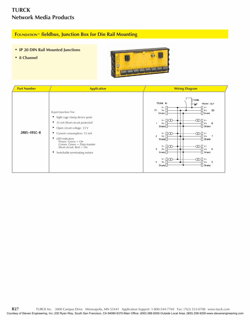
FOUNDATION™ fieldbus, Junction Box for Din Rail Mounting
• IP20 DIN Rail Mounted Junctions
• Available in 4, 6, and 8 Channel
Courtesy of Steven Engineering, Inc.-230 Ryan Way, South San Francisco, CA 94080-6370-Main Office: (650) 588-9200-Outside Local Area: (800) 258-9200-www.stevenengineering.com
TURCK Inc. 3000 Campus Drive Minneapolis, MN 55441 Application Support: 1-800-544-7769 Fax: (763) 553-0708 www.turck.com R26
IndustrialAutomation
FOU
ND
ATIO
Nfie
ldbu
s
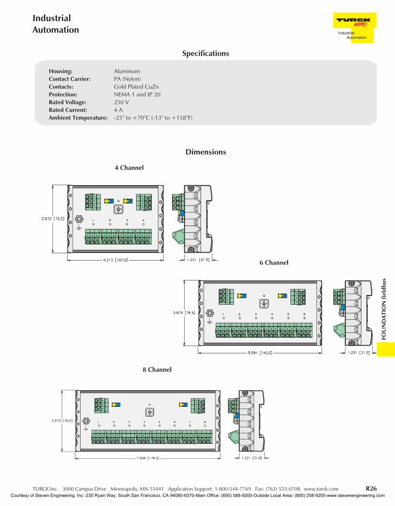
Dimensions
Housing: AluminumContact Carrier: PA (Nylon)Contacts: Gold Plated CuZnProtection: NEMA 1 and IP 20Rated Voltage: 250 VRated Current: 4 AAmbient Temperature: -25° to +70°C (-13° to +158°F)
Specifications
4 Channel
6 Channel
8 Channel
Courtesy of Steven Engineering, Inc.-230 Ryan Way, South San Francisco, CA 94080-6370-Main Office: (650) 588-9200-Outside Local Area: (800) 258-9200-www.stevenengineering.com
R27 TURCK Inc. 3000 Campus Drive Minneapolis, MN 55441 Application Support: 1-800-544-7769 Fax: (763) 553-0708 www.turck.com
TURCKNetwork Media Products
Part Number Application Wiring Diagram
JRBS-49SC-8
8-port Junction Tee
• Eight cage clamp device ports
• 55 mA Short-circuit protected
• Open circuit voltage: 33 V
• Current consumption: 15 mA
• LED indicatorsPower: Green = OnComm: Green = Data transferShort-circuit: Red = On
• Switchable terminating resistor
FOUNDATION™ fieldbus, Junction Box for Din Rail Mounting
• IP 20 DIN Rail Mounted Junctions
• 8 Channel
Courtesy of Steven Engineering, Inc.-230 Ryan Way, South San Francisco, CA 94080-6370-Main Office: (650) 588-9200-Outside Local Area: (800) 258-9200-www.stevenengineering.com
TURCK Inc. 3000 Campus Drive Minneapolis, MN 55441 Application Support: 1-800-544-7769 Fax: (763) 553-0708 www.turck.com R28
IndustrialAutomation
FOU
ND
ATIO
Nfie
ldbu
s
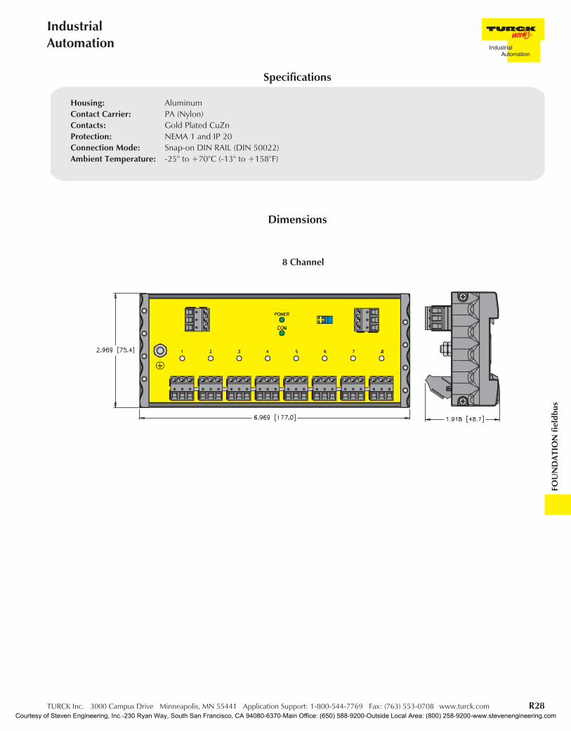
Dimensions
Housing: AluminumContact Carrier: PA (Nylon)Contacts: Gold Plated CuZnProtection: NEMA 1 and IP 20Connection Mode: Snap-on DIN RAIL (DIN 50022)Ambient Temperature: -25° to +70°C (-13° to +158°F)
Specifications
8 Channel
Courtesy of Steven Engineering, Inc.-230 Ryan Way, South San Francisco, CA 94080-6370-Main Office: (650) 588-9200-Outside Local Area: (800) 258-9200-www.stevenengineering.com

R29 TURCK Inc. 3000 Campus Drive Minneapolis, MN 55441 Application Support: 1-800-544-7769 Fax: (763) 553-0708 www.turck.com
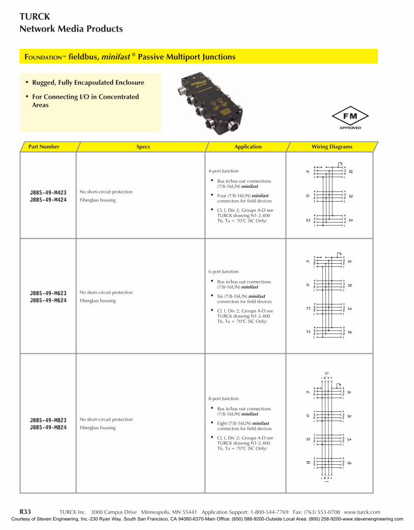
TURCKNetwork Media Products
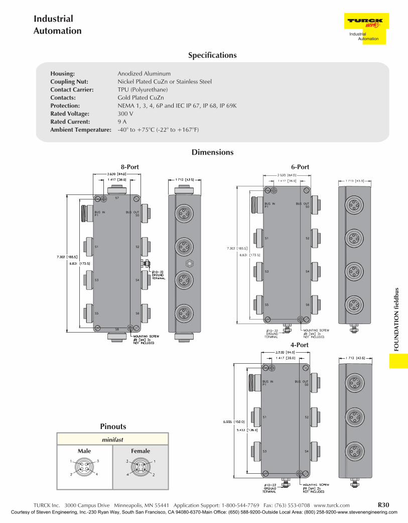
• Rugged, Fully Encapsulated Enclosure
• For Connecting I/O in ConcentratedAreas
FOUNDATION™ fieldbus, minifast ® Passive Multiport Junctions
Part Number Specs Application Wiring Diagrams
JBBS-49-M413JBBS-49-M414
No short-circuit protection
4-port Junction
• Bus in/bus out connections(7/8-16UN) minifast
• Four (7/8-16UN) minifastconnectors for field devices
• CL I, Div 2; Groups A-D seeTURCK drawing N1-2.400T6, Ta = 70°C (SC Only)
JBBS-49-M613JBBS-49-M614
No short-circuit protection
6-port Junction
• Bus in/bus out connections(7/8-16UN) minifast
• Six (7/8-16UN) minifastconnectors for field devices
• CL I, Div 2; Groups A-D seeTURCK drawing N1-2.400T6, Ta = 70°C (SC Only)
JBBS-49-M813JBBS-49-M814
No short-circuit protection
8-port Junction
• Bus in/bus out connections(7/8-16UN) minifast
• Eight (7/8-16UN) minifastconnectors for field devices
• CL I, Div 2; Groups A-D seeTURCK drawing N1-2.400T6, Ta = 70°C (SC Only)
Courtesy of Steven Engineering, Inc.-230 Ryan Way, South San Francisco, CA 94080-6370-Main Office: (650) 588-9200-Outside Local Area: (800) 258-9200-www.stevenengineering.com
TURCK Inc. 3000 Campus Drive Minneapolis, MN 55441 Application Support: 1-800-544-7769 Fax: (763) 553-0708 www.turck.com R30
IndustrialAutomation
FOU
ND
ATIO
Nfie
ldbu
s
Dimensions
minifast
Pinouts
Male Female
Housing: Anodized AluminumCoupling Nut: Nickel Plated CuZn or Stainless SteelContact Carrier: TPU (Polyurethane)Contacts: Gold Plated CuZnProtection: NEMA 1, 3, 4, 6P and IEC IP 67, IP 68, IP 69KRated Voltage: 300 VRated Current: 9 AAmbient Temperature: -40° to +75°C (-22° to +167°F)
Specifications
8-Port
4-Port
6-Port
Courtesy of Steven Engineering, Inc.-230 Ryan Way, South San Francisco, CA 94080-6370-Main Office: (650) 588-9200-Outside Local Area: (800) 258-9200-www.stevenengineering.com

R31 TURCK Inc. 3000 Campus Drive Minneapolis, MN 55441 Application Support: 1-800-544-7769 Fax: (763) 553-0708 www.turck.com
TURCKNetwork Media Products
• Rugged, Fully Encapsulated Enclosure
• For Connecting I/O in ConcentratedAreas
FOUNDATION™ fieldbus, minifast ® Passive Multiport Junctions
Part Number Specs Application Wiring Diagrams
JBBS-49SC-M413
Electrical
• Short-circuit protection: 55 mA (Isc)
• Open circuit voltage: 33 VDC
• Current consumption: <60 mA
Diagnostic
• LED indicatorsPower: Green = OnShort-circuit: Red = Shorted
4-port Junction
• Bus in/bus out connections(7/8-16UN) minifast
• Four (7/8-16UN) minifastconnectors for field devices
CL I, Div 2; Groups A-D see TURCKdrawing N1-2.400T6, Ta = 70°C (SC Only)
JBBS-49SC-M613
Electrical
• Short-circuit protection: 55 mA (Isc)
• Open circuit voltage: 33 VDC
• Current consumption: <60 mA
Diagnostic
• LED indicatorsPower: Green = OnShort-circuit: Red = Shorted
6-port Junction
• Bus in/bus out connections(7/8-16UN) minifast
• Six (7/8-16UN) minifastconnectors for field devices
CL I, Div 2; Groups A-D see TURCKdrawing N1-2.400T6, Ta = 70°C (SC Only)
JBBS-49SC-M813
Electrical
• Short-circuit protection: 55 mA (Isc)
• Open circuit voltage: 33 VDC
• Current consumption: <60 mA
Diagnostic
• LED indicatorsPower: Green = OnShort-circuit: Red = Shorted
8-port Junction
• Bus in/bus out connections(7/8-16UN) minifast
• Eight (7/8-16UN) minifastconnectors for field devices
CL I, Div 2; Groups A-D see TURCKdrawing N1-2.400T6, Ta = 70°C (SC Only)
Courtesy of Steven Engineering, Inc.-230 Ryan Way, South San Francisco, CA 94080-6370-Main Office: (650) 588-9200-Outside Local Area: (800) 258-9200-www.stevenengineering.com

TURCK Inc. 3000 Campus Drive Minneapolis, MN 55441 Application Support: 1-800-544-7769 Fax: (763) 553-0708 www.turck.com R32
IndustrialAutomation
FOU
ND
ATIO
Nfie
ldbu
s
Dimensions
minifast
Pinouts
Male Female
Housing: Anodized AluminumCoupling Nut: Stainless SteelContact Carrier: TPU (Polyurethane)Contacts: Gold Plated CuZnProtection: NEMA 1, 3, 4, 6P and IEC IP 67, IP 68, IP 69KRated Voltage: 300 VRated Current: 9 AAmbient Temperature: -40° to +75°C (-22° to +167°F)
Specifications
8-Port
4-Port
6-Port
Courtesy of Steven Engineering, Inc.-230 Ryan Way, South San Francisco, CA 94080-6370-Main Office: (650) 588-9200-Outside Local Area: (800) 258-9200-www.stevenengineering.com
R33 TURCK Inc. 3000 Campus Drive Minneapolis, MN 55441 Application Support: 1-800-544-7769 Fax: (763) 553-0708 www.turck.com
TURCKNetwork Media Products
• Rugged, Fully Encapsulated Enclosure
• For Connecting I/O in ConcentratedAreas
FOUNDATION™ fieldbus, minifast ® Passive Multiport Junctions
Part Number Specs Application Wiring Diagrams
JBBS-49-M423JBBS-49-M424
No short-circuit protection
Fiberglass housing
4-port Junction
• Bus in/bus out connections(7/8-16UN) minifast
• Four (7/8-16UN) minifastconnectors for field devices
• CL I, Div 2; Groups A-D seeTURCK drawing N1-2.400T6, Ta = 70°C (SC Only)
JBBS-49-M623JBBS-49-M624
No short-circuit protection
Fiberglass housing
6-port Junction
• Bus in/bus out connections(7/8-16UN) minifast
• Six (7/8-16UN) minifastconnectors for field devices
• CL I, Div 2; Groups A-D seeTURCK drawing N1-2.400T6, Ta = 70°C (SC Only)
JBBS-49-M823JBBS-49-M824
No short-circuit protection
Fiberglass housing
8-port Junction
• Bus in/bus out connections(7/8-16UN) minifast
• Eight (7/8-16UN) minifastconnectors for field devices
• CL I, Div 2; Groups A-D seeTURCK drawing N1-2.400T6, Ta = 70°C (SC Only)
Courtesy of Steven Engineering, Inc.-230 Ryan Way, South San Francisco, CA 94080-6370-Main Office: (650) 588-9200-Outside Local Area: (800) 258-9200-www.stevenengineering.com

TURCK Inc. 3000 Campus Drive Minneapolis, MN 55441 Application Support: 1-800-544-7769 Fax: (763) 553-0708 www.turck.com R34
IndustrialAutomation
FOU
ND
ATIO
Nfie
ldbu
s
Dimensions
minifast
Pinouts
Male Female
Housing: FiberglassCoupling Nut: Nickel Plated CuZn or Stainless SteelContact Carrier: TPU (Polyurethane)Contacts: Gold Plated CuZnProtection: NEMA 1, 3, 4, 6P and IEC IP 67, IP 68, IP 69KRated Voltage: 300 VRated Current: 9 AAmbient Temperature: -40° to +75°C (-22° to +167°F)
Specifications
8-Port
4-Port
6-Port
Courtesy of Steven Engineering, Inc.-230 Ryan Way, South San Francisco, CA 94080-6370-Main Office: (650) 588-9200-Outside Local Area: (800) 258-9200-www.stevenengineering.com

R35 TURCK Inc. 3000 Campus Drive Minneapolis, MN 55441 Application Support: 1-800-544-7769 Fax: (763) 553-0708 www.turck.com
TURCKNetwork Media Products
• Rugged, Fully Encapsulated Enclosure
• For Connecting I/O in ConcentratedAreas
FOUNDATION™ fieldbus, minifast ® Passive Multiport Junctions
Part Number Specs Application Wiring Diagrams
JBBS-49-M413/EX No short-circuit protection
4-port Junction
• Bus in/bus out connections(7/8-16UN) minifast
• Four (7/8-16UN) minifastconnectors for field devices
• CL I, Div 2; Groups A-D seeTURCK drawing N1-2.400T6, Ta = 70°C (SC Only)
• FISCO/ENTITY Field Device
JBBS-49-M613/EX No short-circuit protection
6-port Junction
• Bus in/bus out connections(7/8-16UN) minifast
• Six (7/8-16UN) minifastconnectors for field devices
• CL I, Div 2; Groups A-D seeTURCK drawing N1-2.400T6, Ta = 70°C (SC Only)
• FISCO/ENTITY Field Device
Courtesy of Steven Engineering, Inc.-230 Ryan Way, South San Francisco, CA 94080-6370-Main Office: (650) 588-9200-Outside Local Area: (800) 258-9200-www.stevenengineering.com

TURCK Inc. 3000 Campus Drive Minneapolis, MN 55441 Application Support: 1-800-544-7769 Fax: (763) 553-0708 www.turck.com R36
IndustrialAutomation
FOU
ND
ATIO
Nfie
ldbu
s
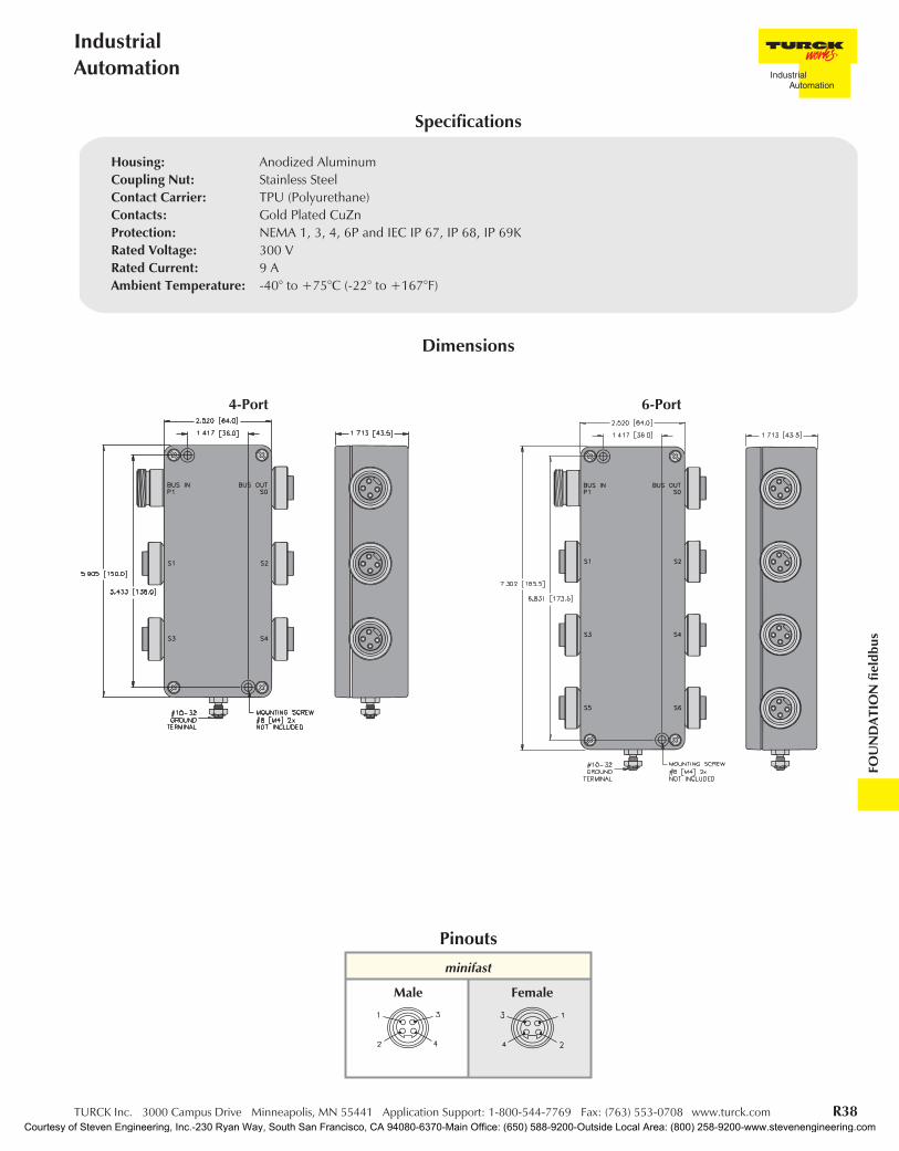
Dimensions
minifast
Pinouts
Male Female
Housing: Anodized AluminumCoupling Nut: Stainless SteelContact Carrier: TPU (Polyurethane)Contacts: Gold Plated CuZnProtection: NEMA 1, 3, 4, 6P and IEC IP 67, IP 68, IP 69KRated Voltage: 300 VRated Current: 9 AAmbient Temperature: -40° to +75°C (-22° to +167°F)
Specifications
4-Port 6-Port
Courtesy of Steven Engineering, Inc.-230 Ryan Way, South San Francisco, CA 94080-6370-Main Office: (650) 588-9200-Outside Local Area: (800) 258-9200-www.stevenengineering.com
R37 TURCK Inc. 3000 Campus Drive Minneapolis, MN 55441 Application Support: 1-800-544-7769 Fax: (763) 553-0708 www.turck.com
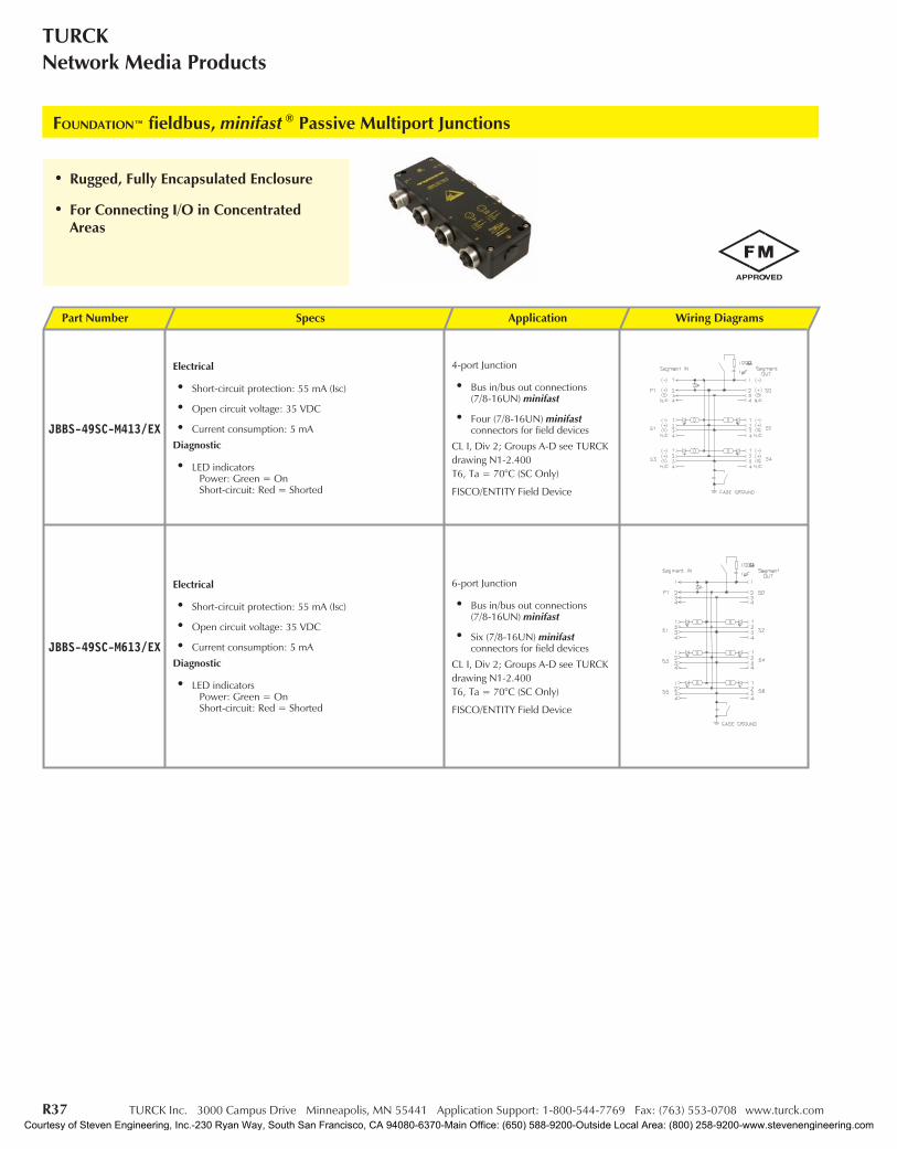
TURCKNetwork Media Products
• Rugged, Fully Encapsulated Enclosure
• For Connecting I/O in ConcentratedAreas
FOUNDATION™ fieldbus, minifast ® Passive Multiport Junctions
Part Number Specs Application Wiring Diagrams
JBBS-49SC-M413/EX
Electrical
• Short-circuit protection: 55 mA (Isc)
• Open circuit voltage: 35 VDC
• Current consumption: 5 mA
Diagnostic
• LED indicatorsPower: Green = OnShort-circuit: Red = Shorted
4-port Junction
• Bus in/bus out connections(7/8-16UN) minifast
• Four (7/8-16UN) minifastconnectors for field devices
CL I, Div 2; Groups A-D see TURCKdrawing N1-2.400T6, Ta = 70°C (SC Only)
FISCO/ENTITY Field Device
JBBS-49SC-M613/EX
Electrical
• Short-circuit protection: 55 mA (Isc)
• Open circuit voltage: 35 VDC
• Current consumption: 5 mA
Diagnostic
• LED indicatorsPower: Green = OnShort-circuit: Red = Shorted
6-port Junction
• Bus in/bus out connections(7/8-16UN) minifast
• Six (7/8-16UN) minifastconnectors for field devices
CL I, Div 2; Groups A-D see TURCKdrawing N1-2.400T6, Ta = 70°C (SC Only)
FISCO/ENTITY Field Device
Courtesy of Steven Engineering, Inc.-230 Ryan Way, South San Francisco, CA 94080-6370-Main Office: (650) 588-9200-Outside Local Area: (800) 258-9200-www.stevenengineering.com
TURCK Inc. 3000 Campus Drive Minneapolis, MN 55441 Application Support: 1-800-544-7769 Fax: (763) 553-0708 www.turck.com R38
IndustrialAutomation
FOU
ND
ATIO
Nfie
ldbu
s
Dimensions
minifast
Pinouts
Male Female
Housing: Anodized AluminumCoupling Nut: Stainless SteelContact Carrier: TPU (Polyurethane)Contacts: Gold Plated CuZnProtection: NEMA 1, 3, 4, 6P and IEC IP 67, IP 68, IP 69KRated Voltage: 300 VRated Current: 9 AAmbient Temperature: -40° to +75°C (-22° to +167°F)
Specifications
4-Port 6-Port
Courtesy of Steven Engineering, Inc.-230 Ryan Way, South San Francisco, CA 94080-6370-Main Office: (650) 588-9200-Outside Local Area: (800) 258-9200-www.stevenengineering.com
R39 TURCK Inc. 3000 Campus Drive Minneapolis, MN 55441 Application Support: 1-800-544-7769 Fax: (763) 553-0708 www.turck.com
TURCKNetwork Media Products
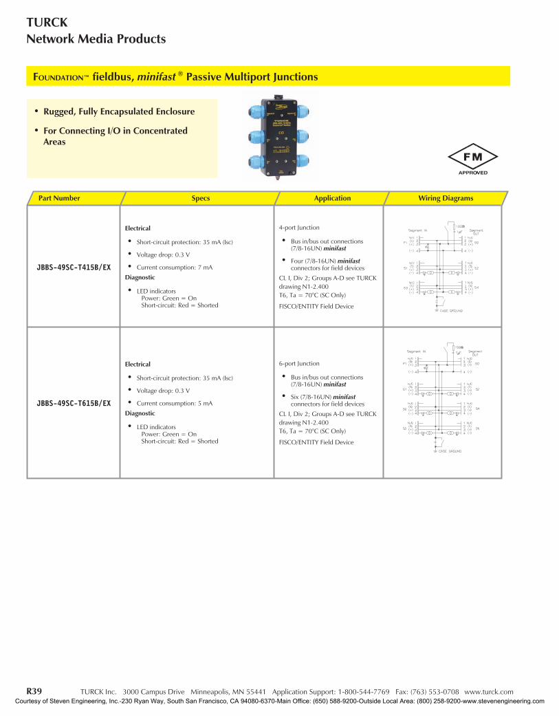
• Rugged, Fully Encapsulated Enclosure
• For Connecting I/O in ConcentratedAreas
FOUNDATION™ fieldbus, minifast ® Passive Multiport Junctions
Part Number Specs Application Wiring Diagrams
JBBS-49SC-T415B/EX
Electrical
• Short-circuit protection: 35 mA (Isc)
• Voltage drop: 0.3 V
• Current consumption: 7 mA
Diagnostic
• LED indicatorsPower: Green = OnShort-circuit: Red = Shorted
4-port Junction
• Bus in/bus out connections(7/8-16UN) minifast
• Four (7/8-16UN) minifastconnectors for field devices
CL I, Div 2; Groups A-D see TURCKdrawing N1-2.400T6, Ta = 70°C (SC Only)
FISCO/ENTITY Field Device
JBBS-49SC-T615B/EX
Electrical
• Short-circuit protection: 35 mA (Isc)
• Voltage drop: 0.3 V
• Current consumption: 5 mA
Diagnostic
• LED indicatorsPower: Green = OnShort-circuit: Red = Shorted
6-port Junction
• Bus in/bus out connections(7/8-16UN) minifast
• Six (7/8-16UN) minifastconnectors for field devices
CL I, Div 2; Groups A-D see TURCKdrawing N1-2.400T6, Ta = 70°C (SC Only)
FISCO/ENTITY Field Device
Courtesy of Steven Engineering, Inc.-230 Ryan Way, South San Francisco, CA 94080-6370-Main Office: (650) 588-9200-Outside Local Area: (800) 258-9200-www.stevenengineering.com
TURCK Inc. 3000 Campus Drive Minneapolis, MN 55441 Application Support: 1-800-544-7769 Fax: (763) 553-0708 www.turck.com R40
IndustrialAutomation
FOU
ND
ATIO
Nfie
ldbu
s
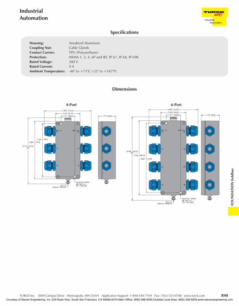
Dimensions
Housing: Anodized AluminumCoupling Nut: Cable GlandsContact Carrier: TPU (Polyurethane)Protection: NEMA 1, 3, 4, 6P and IEC IP 67, IP 68, IP 69KRated Voltage: 300 VRated Current: 9 AAmbient Temperature: -40° to +75°C (-22° to +167°F)
Specifications
4-Port 6-Port
Courtesy of Steven Engineering, Inc.-230 Ryan Way, South San Francisco, CA 94080-6370-Main Office: (650) 588-9200-Outside Local Area: (800) 258-9200-www.stevenengineering.com
R41 TURCK Inc. 3000 Campus Drive Minneapolis, MN 55441 Application Support: 1-800-544-7769 Fax: (763) 553-0708 www.turck.com
TURCKNetwork Media Products
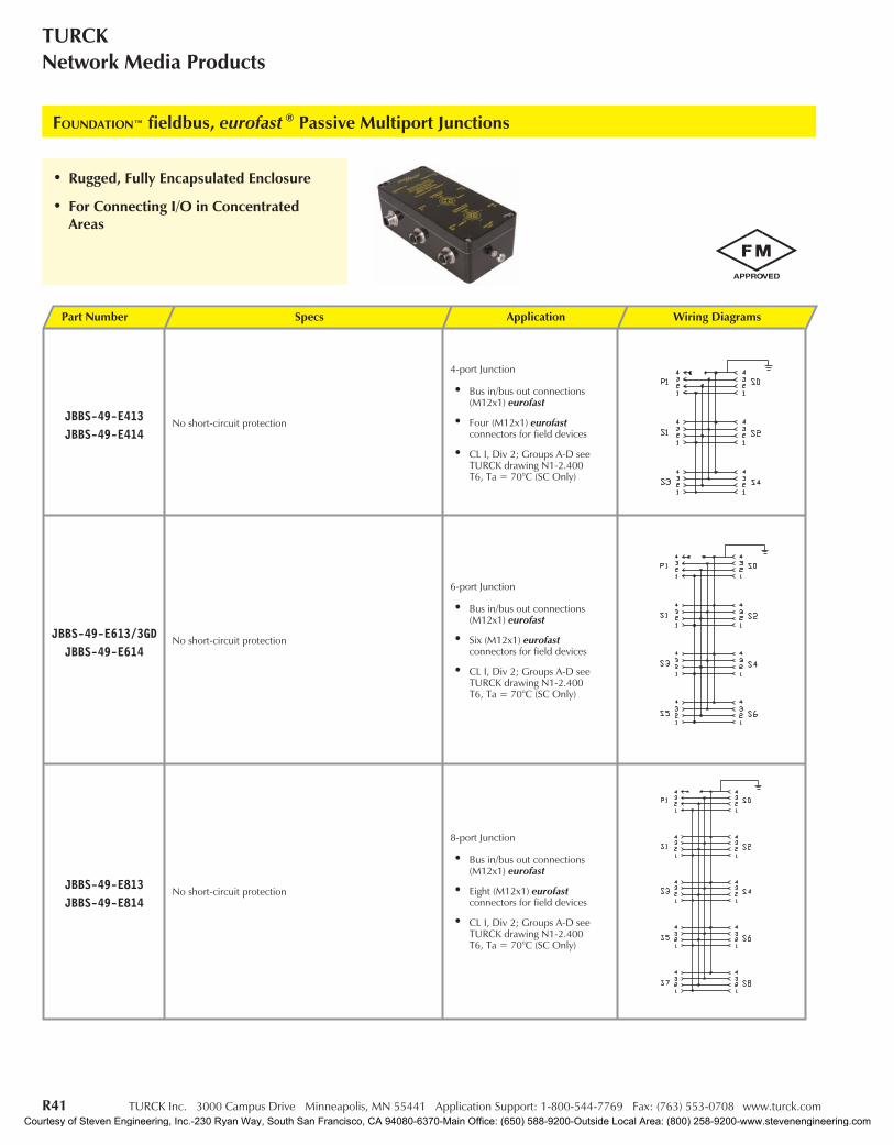
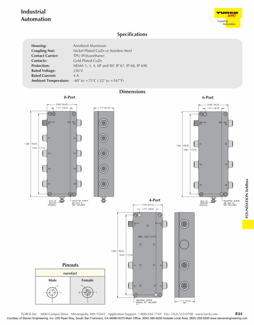
FOUNDATION™ fieldbus, eurofast ® Passive Multiport Junctions
• Rugged, Fully Encapsulated Enclosure
• For Connecting I/O in ConcentratedAreas
Part Number Specs Application Wiring Diagrams
JBBS-49-E413JBBS-49-E414
No short-circuit protection
4-port Junction
• Bus in/bus out connections(M12x1) eurofast
• Four (M12x1) eurofastconnectors for field devices
• CL I, Div 2; Groups A-D seeTURCK drawing N1-2.400T6, Ta = 70°C (SC Only)
JBBS-49-E613/3GDJBBS-49-E614
No short-circuit protection
6-port Junction
• Bus in/bus out connections(M12x1) eurofast
• Six (M12x1) eurofastconnectors for field devices
• CL I, Div 2; Groups A-D seeTURCK drawing N1-2.400T6, Ta = 70°C (SC Only)
JBBS-49-E813JBBS-49-E814
No short-circuit protection
8-port Junction
• Bus in/bus out connections(M12x1) eurofast
• Eight (M12x1) eurofastconnectors for field devices
• CL I, Div 2; Groups A-D seeTURCK drawing N1-2.400T6, Ta = 70°C (SC Only)
Courtesy of Steven Engineering, Inc.-230 Ryan Way, South San Francisco, CA 94080-6370-Main Office: (650) 588-9200-Outside Local Area: (800) 258-9200-www.stevenengineering.com
TURCK Inc. 3000 Campus Drive Minneapolis, MN 55441 Application Support: 1-800-544-7769 Fax: (763) 553-0708 www.turck.com R42
IndustrialAutomation
FOU
ND
ATIO
Nfie
ldbu
s
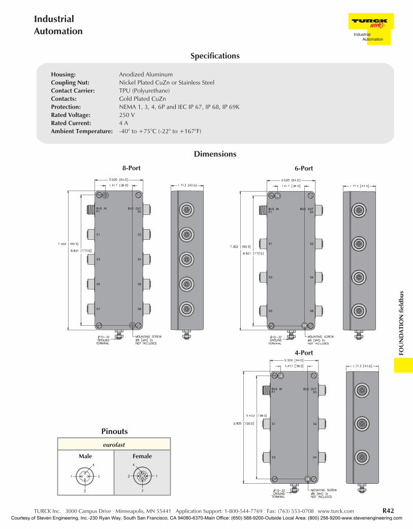
Dimensions
eurofast
Pinouts
Male Female
Housing: Anodized AluminumCoupling Nut: Nickel Plated CuZn or Stainless SteelContact Carrier: TPU (Polyurethane)Contacts: Gold Plated CuZnProtection: NEMA 1, 3, 4, 6P and IEC IP 67, IP 68, IP 69KRated Voltage: 250 VRated Current: 4 AAmbient Temperature: -40° to +75°C (-22° to +167°F)
Specifications
8-Port
4-Port
6-Port
Courtesy of Steven Engineering, Inc.-230 Ryan Way, South San Francisco, CA 94080-6370-Main Office: (650) 588-9200-Outside Local Area: (800) 258-9200-www.stevenengineering.com

R43 TURCK Inc. 3000 Campus Drive Minneapolis, MN 55441 Application Support: 1-800-544-7769 Fax: (763) 553-0708 www.turck.com
TURCKNetwork Media Products
FOUNDATION™ fieldbus, eurofast ® Passive Multiport Junctions
• Rugged, Fully Encapsulated Enclosure
• For Connecting I/O in ConcentratedAreas
Part Number Specs Application Wiring Diagrams
JBBS-49SC-E413
Electrical
• Short-circuit protection: 55 mA (Isc)
• Open circuit voltage: 35 VDC
• Current consumption: 5 mA
Diagnostic
• LED indicatorsPower: Green = OnShort-circuit: Red = Shorted
4-port Junction
• Bus in/bus out connections(M12x1) eurofast
• Four (M12x1) eurofastconnectors for field devices
CL I, Div 2; Groups A-D see TURCKdrawing N1-2.400T6, Ta = 70°C (SC Only)
JBBS-49SC-E613
Electrical
• Short-circuit protection: 55 mA (Isc)
• Open circuit voltage: 35 VDC
• Current consumption: 5 mA
Diagnostic
• LED indicatorsPower: Green = OnShort-circuit: Red = Shorted
6-port Junction
• Bus in/bus out connections(M12x1) eurofast
• Six (M12x1) eurofastconnectors for field devices
CL I, Div 2; Groups A-D see TURCKdrawing N1-2.400T6, Ta = 70°C (SC Only)
JBBS-49SC-E813
Electrical
• Short-circuit protection: 55 mA (Isc)
• Open circuit voltage: 35 VDC
• Current consumption: 5 mA
Diagnostic
• LED indicatorsPower: Green = OnShort-circuit: Red = Shorted
8-port Junction
• Bus in/bus out connections(M12x1) eurofast
• Eight (M12x1) eurofastconnectors for field devices
CL I, Div 2; Groups A-Dsee TURCK drawing
N1-2.400T6, Ta = 70°C (SC Only)
Courtesy of Steven Engineering, Inc.-230 Ryan Way, South San Francisco, CA 94080-6370-Main Office: (650) 588-9200-Outside Local Area: (800) 258-9200-www.stevenengineering.com
TURCK Inc. 3000 Campus Drive Minneapolis, MN 55441 Application Support: 1-800-544-7769 Fax: (763) 553-0708 www.turck.com R44
IndustrialAutomation
FOU
ND
ATIO
Nfie
ldbu
s
Dimensions
eurofast
Pinouts
Male Female
Housing: Anodized AluminumCoupling Nut: Nickel Plated CuZn or Stainless SteelContact Carrier: TPU (Polyurethane)Contacts: Gold Plated CuZnProtection: NEMA 1, 3, 4, 6P and IEC IP 67, IP 68, IP 69KRated Voltage: 250 VRated Current: 4 AAmbient Temperature: -40° to +75°C (-22° to +167°F)
Specifications
8-Port
4-Port
6-Port
Courtesy of Steven Engineering, Inc.-230 Ryan Way, South San Francisco, CA 94080-6370-Main Office: (650) 588-9200-Outside Local Area: (800) 258-9200-www.stevenengineering.com

R45 TURCK Inc. 3000 Campus Drive Minneapolis, MN 55441 Application Support: 1-800-544-7769 Fax: (763) 553-0708 www.turck.com
TURCKNetwork Media Products
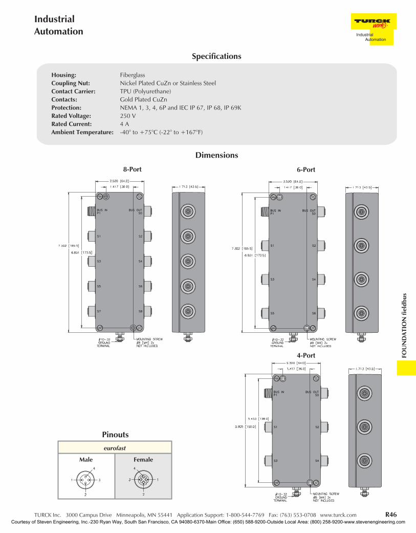
FOUNDATION™ fieldbus, eurofast ® Passive Multiport Junctions
• Rugged, Fully Encapsulated Enclosure
• For Connecting I/O in ConcentratedAreas
Part Number Specs Application Wiring Diagrams
JBBS-49-E423JBBS-49-E424
No short-circuit protection
4-port Junction
• Bus in/bus out connections(M12x1) eurofast
• Four (M12x1) eurofastconnectors for field devices
• CL I, Div 2; Groups A-D seeTURCK drawing N1-2.400T6, Ta = 70°C (SC Only)
JBBS-49-E623JBBS-49-E624
No short-circuit protection
6-port Junction
• Bus in/bus out connections(M12x1) eurofast
• Six (M12x1) eurofastconnectors for field devices
• CL I, Div 2; Groups A-D seeTURCK drawing N1-2.400T6, Ta = 70°C (SC Only)
JBBS-49-E823JBBS-49-E824
No short-circuit protection
8-port Junction
• Bus in/bus out connections(M12x1) eurofast
• Eight (M12x1) eurofastconnectors for field devices
• CL I, Div 2; Groups A-D seeTURCK drawing N1-2.400T6, Ta = 70°C (SC Only)
Courtesy of Steven Engineering, Inc.-230 Ryan Way, South San Francisco, CA 94080-6370-Main Office: (650) 588-9200-Outside Local Area: (800) 258-9200-www.stevenengineering.com
TURCK Inc. 3000 Campus Drive Minneapolis, MN 55441 Application Support: 1-800-544-7769 Fax: (763) 553-0708 www.turck.com R46
IndustrialAutomation
FOU
ND
ATIO
Nfie
ldbu
s
Dimensions
eurofast
Pinouts
Male Female
Housing: FiberglassCoupling Nut: Nickel Plated CuZn or Stainless SteelContact Carrier: TPU (Polyurethane)Contacts: Gold Plated CuZnProtection: NEMA 1, 3, 4, 6P and IEC IP 67, IP 68, IP 69KRated Voltage: 250 VRated Current: 4 AAmbient Temperature: -40° to +75°C (-22° to +167°F)
Specifications
8-Port
4-Port
6-Port
Courtesy of Steven Engineering, Inc.-230 Ryan Way, South San Francisco, CA 94080-6370-Main Office: (650) 588-9200-Outside Local Area: (800) 258-9200-www.stevenengineering.com
R47 TURCK Inc. 3000 Campus Drive Minneapolis, MN 55441 Application Support: 1-800-544-7769 Fax: (763) 553-0708 www.turck.com
TURCKNetwork Media Products
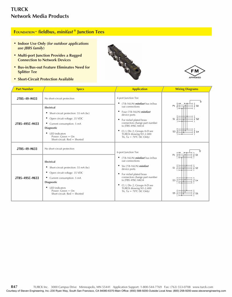
FOUNDATION™ fieldbus, minifast ® Junction Tees
• Indoor Use Only (for outdoor applicationsuse JBBS family)
• Multi-port Junction Provides a RuggedConnection to Network Devices
• Bus-in/Bus-out Feature Eliminates Need forSplitter Tee
• Short-Circuit Protection Available
Part Number Specs Application Wiring Diagrams
JTBS-49-M433 No short-circuit protection 4-port Junction Tee
• (7/8-16UN) minifast bus in/busout connections
• Four (7/8-16UN) minifastdevice ports
• For nickel plated brassconnectors change part numberto JTBS 49SC-M434
• CL I, Div 2; Groups A-D seeTURCK drawing N1-2.400T6, Ta = 70°C (SC Only)
JTBS-49SC-M433
Electrical
• Short-circuit protection: 55 mA (Isc)
• Open circuit voltage: 35 VDC
• Current consumption: 5 mA
Diagnostic
• LED indicatorsPower: Green = OnShort-circuit: Red = Shorted
JTBS-49-M633 No short-circuit protection6-port Junction Tee
• (7/8-16UN) minifast bus in/busout connections
• Six (7/8-16UN) minifastdevice ports
• For nickel plated brassconnectors change part numberto JTBS 49SC-M634
• CL I, Div 2; Groups A-D seeTURCK drawing N1-2.400T6, Ta = 70°C (SC Only)
JTBS-49SC-M633
Electrical
• Short-circuit protection: 55 mA (Isc)
• Open circuit voltage: 35 VDC
• Current consumption: 5 mA
Diagnostic
• LED indicatorsPower: Green = OnShort-circuit: Red = Shorted
Courtesy of Steven Engineering, Inc.-230 Ryan Way, South San Francisco, CA 94080-6370-Main Office: (650) 588-9200-Outside Local Area: (800) 258-9200-www.stevenengineering.com
TURCK Inc. 3000 Campus Drive Minneapolis, MN 55441 Application Support: 1-800-544-7769 Fax: (763) 553-0708 www.turck.com R48
IndustrialAutomation
FOU
ND
ATIO
Nfie
ldbu
s
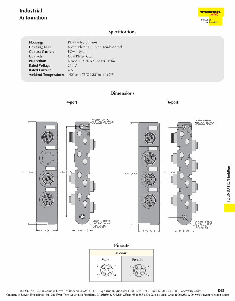
4-port 6-port
Dimensions
minifast
Pinouts
Male Female
Housing: PUR (Polyurethane)Coupling Nut: Nickel Plated CuZn or Stainless SteelContact Carrier: POM (Nylon)Contacts: Gold Plated CuZnProtection: NEMA 1, 3, 4, 6P and IEC IP 68Rated Voltage: 250 VRated Current: 4 AAmbient Temperature: -40° to +75°C (-22° to +167°F)
Specifications
Courtesy of Steven Engineering, Inc.-230 Ryan Way, South San Francisco, CA 94080-6370-Main Office: (650) 588-9200-Outside Local Area: (800) 258-9200-www.stevenengineering.com

R49 TURCK Inc. 3000 Campus Drive Minneapolis, MN 55441 Application Support: 1-800-544-7769 Fax: (763) 553-0708 www.turck.com
TURCKNetwork Media Products
FOUNDATION™ fieldbus, eurofast ® Junction Tees
• Indoor Use Only (for outdoor applicationsuse JBBS family)
• Multi-port Junction Provides a RuggedConnection to Network Devices
• Bus-in/Bus-out Feature Eliminates Need forSplitter Tee
• Short-Circuit Protection Available
Part Number Specs Application Wiring Diagrams
JTBS-49-E433 No short-circuit protection4-port Junction Tee
• (M12x1) eurofast bus in/bus outconnections
• Four (M12x1) eurofastdevice ports
• For nickel plated brassconnectors change part numberto JTBS 49SC-E434
• Short-circuit threshold: 280 mA
• CL I, Div 2; Groups A-D seeTURCK drawing N1-2.400T6, Ta = 70°C (SC Only)
JTBS-49SC-E433
Electrical
• Short-circuit protection: 55 mA (Isc)
• Open circuit voltage: 35 VDC
• Current consumption: 5 mA
Diagnostic
• LED indicatorsPower: Green = OnShort-circuit: Red = Shorted
JTBS-49-E633 No short-circuit protection 6-port Junction Tee
• (M12x1) eurofast bus in/bus outconnections
• Six (M12x1) eurofastdevice ports
• For nickel plated brassconnectors change part numberto JTBS 49SC-E634
• Short-circuit threshold: 280 mA
• CL I, Div 2; Groups A-D seeTURCK drawing N1-2.400T6, Ta = 70°C (SC Only)
JTBS-49SC-E633
Electrical
• Short-circuit protection: 55 mA (Isc)
• Open circuit voltage: 35 VDC
• Current consumption: 5 mA
Diagnostic
• LED indicatorsPower: Green = OnShort-circuit: Red = Shorted
Courtesy of Steven Engineering, Inc.-230 Ryan Way, South San Francisco, CA 94080-6370-Main Office: (650) 588-9200-Outside Local Area: (800) 258-9200-www.stevenengineering.com

TURCK Inc. 3000 Campus Drive Minneapolis, MN 55441 Application Support: 1-800-544-7769 Fax: (763) 553-0708 www.turck.com R50
IndustrialAutomation
FOU
ND
ATIO
Nfie
ldbu
s
4-port 6-port
Dimensions
minifast eurofast
Pinouts
FemaleMaleFemale
Housing: PUR (Polyurethane)Coupling Nut: Nickel Plated CuZn or Stainless SteelContact Carrier: POM (Nylon)Contacts: Gold Plated CuZnProtection: NEMA 1, 3, 4, 6P and IEC IP 68Rated Voltage: 250 VRated Current: 4 AAmbient Temperature: -40° to +75°C (-22° to +167°F)
Specifications
Courtesy of Steven Engineering, Inc.-230 Ryan Way, South San Francisco, CA 94080-6370-Main Office: (650) 588-9200-Outside Local Area: (800) 258-9200-www.stevenengineering.com
R51 TURCK Inc. 3000 Campus Drive Minneapolis, MN 55441 Application Support: 1-800-544-7769 Fax: (763) 553-0708 www.turck.com
TURCKNetwork Media Products
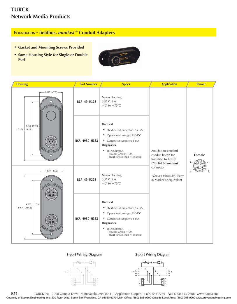
FOUNDATION™ fieldbus, minifast ® Conduit Adapters
1-port Wiring Diagram 2-port Wiring Diagram
• Gasket and Mounting Screws Provided
• Same Housing Style for Single or DoublePort
Housing Part Number Specs Application Pinout
BCA 49-M123Nylon Housing300 V, 9 A-40° to +75°C
Attaches to standardconduit body* fortransition to 4-wire(7/8-16UN) minifastconnector
*Crouse Hinds 3/4" Form8, Mark 9 or equivalent
BCA 49SC-M123
Electrical
• Short-circuit protection: 55 mA
• Open circuit voltage: 35 VDC
• Current consumption: 5 mA
Diagnostics
• LED indicatorsPower: Green = OnShort-circuit: Red = Shorted
BCA 49-M223Nylon Housing300 V, 9 A-40° to +75°C
BCA 49SC-M223
Electrical
• Short-circuit protection: 55 mA
• Open circuit voltage: 35 VDC
• Current consumption: 5 mA
Diagnostics
• LED indicatorsPower: Green = OnShort-circuit: Red = Shorted
Female
Courtesy of Steven Engineering, Inc.-230 Ryan Way, South San Francisco, CA 94080-6370-Main Office: (650) 588-9200-Outside Local Area: (800) 258-9200-www.stevenengineering.com
TURCK Inc. 3000 Campus Drive Minneapolis, MN 55441 Application Support: 1-800-544-7769 Fax: (763) 553-0708 www.turck.com R52
IndustrialAutomation
FOU
ND
ATIO
Nfie
ldbu
s
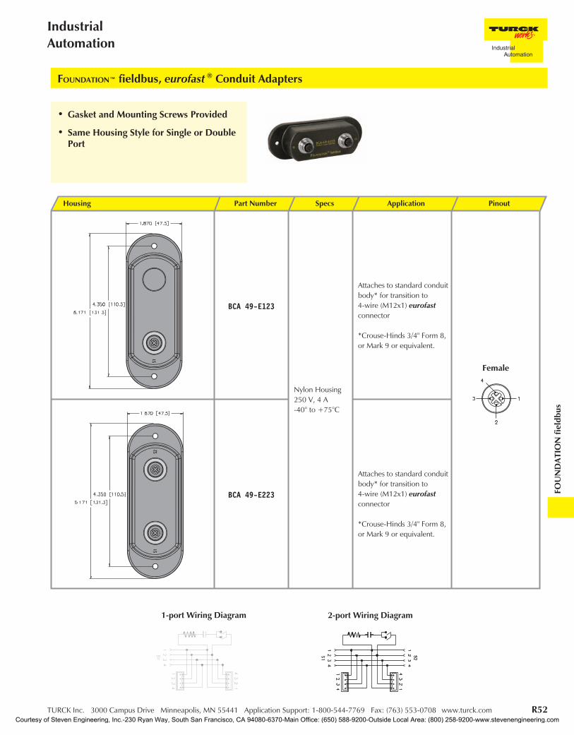
FOUNDATION™ fieldbus, eurofast ® Conduit Adapters
• Gasket and Mounting Screws Provided
• Same Housing Style for Single or DoublePort
1-port Wiring Diagram 2-port Wiring Diagram
Housing Part Number Specs Application Pinout
BCA 49-E123
Nylon Housing250 V, 4 A-40° to +75°C
Attaches to standard conduitbody* for transition to4-wire (M12x1) eurofastconnector
*Crouse-Hinds 3/4" Form 8,or Mark 9 or equivalent.
BCA 49-E223
Attaches to standard conduitbody* for transition to4-wire (M12x1) eurofastconnector
*Crouse-Hinds 3/4" Form 8,or Mark 9 or equivalent.
Female
Courtesy of Steven Engineering, Inc.-230 Ryan Way, South San Francisco, CA 94080-6370-Main Office: (650) 588-9200-Outside Local Area: (800) 258-9200-www.stevenengineering.com
R53 TURCK Inc. 3000 Campus Drive Minneapolis, MN 55441 Application Support: 1-800-544-7769 Fax: (763) 553-0708 www.turck.com
TURCKNetwork Media Products
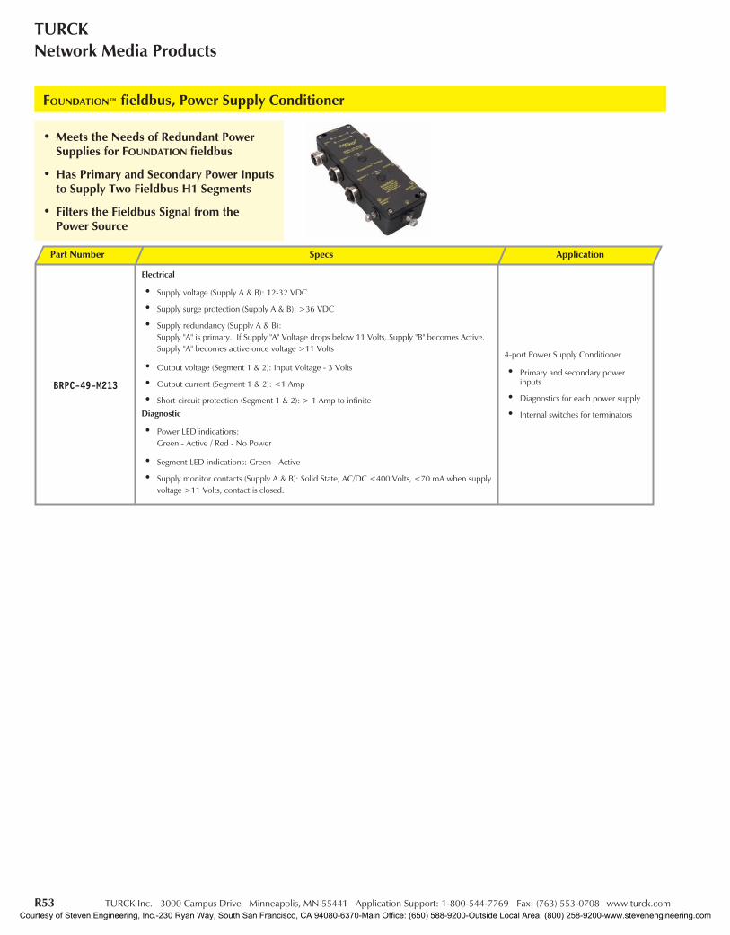
FOUNDATION™ fieldbus, Power Supply Conditioner
• Meets the Needs of Redundant PowerSupplies for FOUNDATION fieldbus
• Has Primary and Secondary Power Inputsto Supply Two Fieldbus H1 Segments
• Filters the Fieldbus Signal from thePower Source
Part Number Specs Application
BRPC-49-M213
Electrical
• Supply voltage (Supply A & B): 12-32 VDC
• Supply surge protection (Supply A & B): >36 VDC
• Supply redundancy (Supply A & B):Supply "A" is primary. If Supply "A" Voltage drops below 11 Volts, Supply "B" becomes Active.Supply "A" becomes active once voltage >11 Volts
• Output voltage (Segment 1 & 2): Input Voltage - 3 Volts
• Output current (Segment 1 & 2): <1 Amp
• Short-circuit protection (Segment 1 & 2): > 1 Amp to infinite
Diagnostic
• Power LED indications:Green - Active / Red - No Power
• Segment LED indications: Green - Active
• Supply monitor contacts (Supply A & B): Solid State, AC/DC <400 Volts, <70 mA when supplyvoltage >11 Volts, contact is closed.
4-port Power Supply Conditioner
• Primary and secondary powerinputs
• Diagnostics for each power supply
• Internal switches for terminators
Courtesy of Steven Engineering, Inc.-230 Ryan Way, South San Francisco, CA 94080-6370-Main Office: (650) 588-9200-Outside Local Area: (800) 258-9200-www.stevenengineering.com
TURCK Inc. 3000 Campus Drive Minneapolis, MN 55441 Application Support: 1-800-544-7769 Fax: (763) 553-0708 www.turck.com R54
IndustrialAutomation
FOU
ND
ATIO
Nfie
ldbu
s
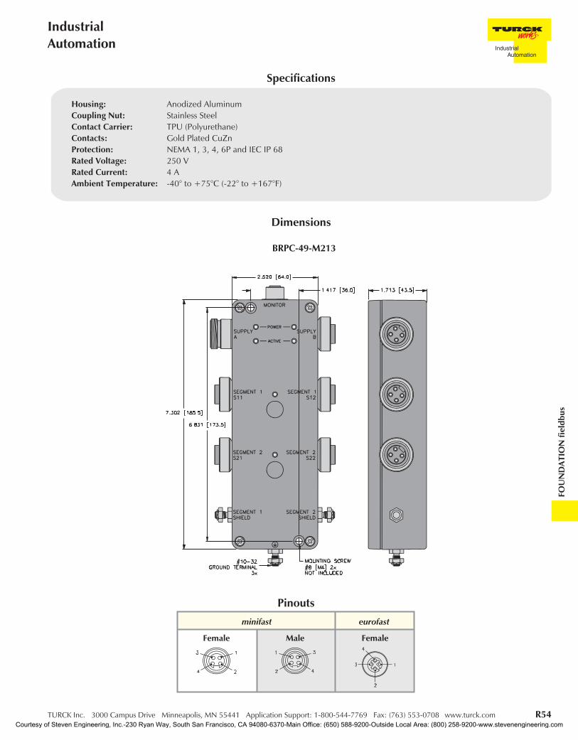
BRPC-49-M213
Dimensions
minifast eurofast
Pinouts
Housing: Anodized AluminumCoupling Nut: Stainless SteelContact Carrier: TPU (Polyurethane)Contacts: Gold Plated CuZnProtection: NEMA 1, 3, 4, 6P and IEC IP 68Rated Voltage: 250 VRated Current: 4 AAmbient Temperature: -40° to +75°C (-22° to +167°F)
Specifications
FemaleMaleFemale
Courtesy of Steven Engineering, Inc.-230 Ryan Way, South San Francisco, CA 94080-6370-Main Office: (650) 588-9200-Outside Local Area: (800) 258-9200-www.stevenengineering.com
R55 TURCK Inc. 3000 Campus Drive Minneapolis, MN 55441 Application Support: 1-800-544-7769 Fax: (763) 553-0708 www.turck.com
TURCKNetwork Media Products
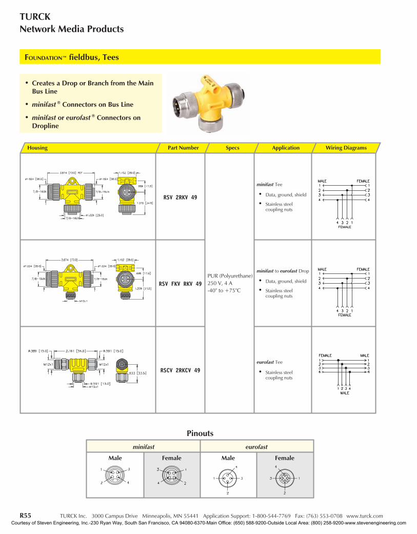
Housing Part Number Specs Application Wiring Diagrams
RSV 2RKV 49
PUR (Polyurethane)250 V, 4 A-40° to +75°C
minifast Tee
• Data, ground, shield
• Stainless steelcoupling nuts
RSV FKV RKV 49
minifast to eurofast Drop
• Data, ground, shield
• Stainless steelcoupling nuts
RSCV 2RKCV 49eurofast Tee
• Stainless steelcoupling nuts
FOUNDATION™ fieldbus, Tees
minifast eurofast
Pinouts
Male Female Male Female
• Creates a Drop or Branch from the MainBus Line
• minifast ® Connectors on Bus Line
• minifast or eurofast ® Connectors onDropline
Courtesy of Steven Engineering, Inc.-230 Ryan Way, South San Francisco, CA 94080-6370-Main Office: (650) 588-9200-Outside Local Area: (800) 258-9200-www.stevenengineering.com
TURCK Inc. 3000 Campus Drive Minneapolis, MN 55441 Application Support: 1-800-544-7769 Fax: (763) 553-0708 www.turck.com R56
IndustrialAutomation
FOU
ND
ATIO
Nfie
ldbu
s
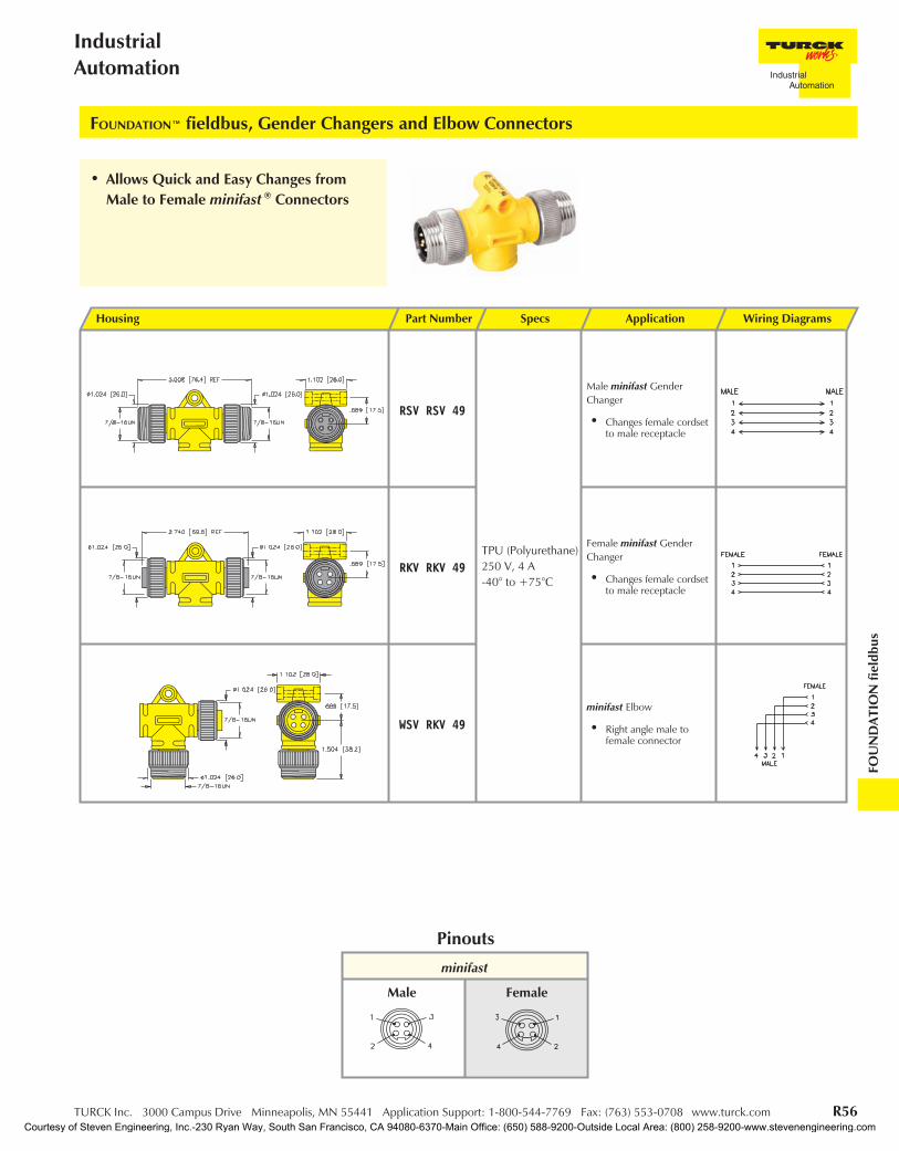
FOUNDATION™ fieldbus, Gender Changers and Elbow Connectors
Housing Part Number Specs Application Wiring Diagrams
RSV RSV 49
TPU (Polyurethane)250 V, 4 A-40° to +75°C
Male minifast GenderChanger
• Changes female cordsetto male receptacle
RKV RKV 49
Female minifast GenderChanger
• Changes female cordsetto male receptacle
WSV RKV 49minifast Elbow
• Right angle male tofemale connector
minifast
Pinouts
Male Female
• Allows Quick and Easy Changes fromMale to Female minifast ® Connectors
Courtesy of Steven Engineering, Inc.-230 Ryan Way, South San Francisco, CA 94080-6370-Main Office: (650) 588-9200-Outside Local Area: (800) 258-9200-www.stevenengineering.com

R57 TURCK Inc. 3000 Campus Drive Minneapolis, MN 55441 Application Support: 1-800-544-7769 Fax: (763) 553-0708 www.turck.com
TURCKNetwork Media Products
Housing Part Number Specs Application Pinouts
See Drawing 1 RSV RKV 49 SS
Electrical
• Maximum operating voltage: 27 Volts
• Maximum operating current: 200mA
• Clamping action turn-on: 28.5 Volts
• Maximum clamping at 2 kA: (8 x 20 Sec): 44 Volts
• Maximum surge voltage: 20 kV
• Maximum surge current: 2.5 kA
• Current leakage/line at operating voltage: 5 A
• Capacitance /line at operating voltage: 500 pF
• Response time: less than 1 nanosecond
Mechanical
• Ground stud: 10-32 stainless steel
• Operating temperature: -40° to +85°C
Male and Female minifast ®,4-pin
FOUNDATION™ fieldbus, Surge Suppressor
Male
Female
• Protects Data Communication Lines (V+ and V-)
• Absorbs the Front End of the Transient,Responding in Less Than a Nanosecond
• Diverts the Surge Energy to Ground
• Automatically Resets and waits for Next Surge
1
Courtesy of Steven Engineering, Inc.-230 Ryan Way, South San Francisco, CA 94080-6370-Main Office: (650) 588-9200-Outside Local Area: (800) 258-9200-www.stevenengineering.com
TURCK Inc. 3000 Campus Drive Minneapolis, MN 55441 Application Support: 1-800-544-7769 Fax: (763) 553-0708 www.turck.com R58
IndustrialAutomation
FOU
ND
ATIO
Nfie
ldbu
s
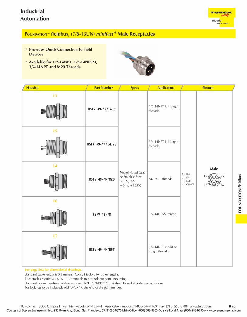
FOUNDATION™ fieldbus, (7/8-16UN) minifast ® Male Receptacles
• Provides Quick Connection to FieldDevices
• Available for 1/2-14NPT, 1/2-14NPSM,3/4-14NPT and M20 Threads
13
15
16
17
Housing Part Number Specs Application Pinouts
RSFV 49-*M/14.5
Nickel Plated CuZnor Stainless Steel300 V, 9 A-40° to +105°C
1/2-14NPT full lengththreads
1. BU2. BN3. N/C4. GN/YE
RSFV 49-*M/14.753/4-14NPT full lengththreads
RSFV 49-*M/M20 M20x1.5 threads
RSFV 49-*M 1/2-14NPSM threads
RSFV 49-*M/NPT1/2-14NPT modifiedlength threads
See page R62 for dimensional drawings.Standard cable length is 0.3 meters. Consult factory for other lengths.Receptacles require a 13/16" (21.0 mm) clearance hole for panel mounting.Standard housing material is stainless steel. "RKF .."; "RKFV .." indicates 316 nickel plated brass housing.For locknuts to be included, add "W/LN" to the end of the part number.
14Male
Courtesy of Steven Engineering, Inc.-230 Ryan Way, South San Francisco, CA 94080-6370-Main Office: (650) 588-9200-Outside Local Area: (800) 258-9200-www.stevenengineering.com

R59 TURCK Inc. 3000 Campus Drive Minneapolis, MN 55441 Application Support: 1-800-544-7769 Fax: (763) 553-0708 www.turck.com
TURCKNetwork Media Products
FOUNDATION™ fieldbus, (7/8-16UN) minifast ® Female Receptacles
• Provides Quick Connection to FieldDevices
• Available for 1/2-14NPT, 1/2-14NPSM,3/4-14NPT and M20 Threads
Housing Part Number Specs Application Pinouts
RKFV 49-*M/14.5
Nickel Plated CuZnor Stainless Steel300 V, 9 A-40° to +105°C
1/2-14NPT full lengththreads
1. BU2. BN3. GY4. GN/YE
RKFV 49-*M/14.753/4-14NPT full lengththreads
RKFV 49-*M/M20 M20x1.5 threads
RKFV 49-*M 1/2-14NPSM threads
RKFV 49-*M/NPT1/2-14NPT modifiedlength threads
See page R63 for dimensional drawings.Standard cable length is 0.3 meters. Consult factory for other lengths.Receptacles require a 13/16" (21.0 mm) clearance hole for panel mounting.Standard housing material is stainless steel. "RKF .."; indicates 316 nickel plated brass housing.For locknuts to be included, add "W/LN" to the end of the part number.
21
18
20
19
22
Female
Courtesy of Steven Engineering, Inc.-230 Ryan Way, South San Francisco, CA 94080-6370-Main Office: (650) 588-9200-Outside Local Area: (800) 258-9200-www.stevenengineering.com
TURCK Inc. 3000 Campus Drive Minneapolis, MN 55441 Application Support: 1-800-544-7769 Fax: (763) 553-0708 www.turck.com R60
IndustrialAutomation
FOU
ND
ATIO
Nfie
ldbu
s
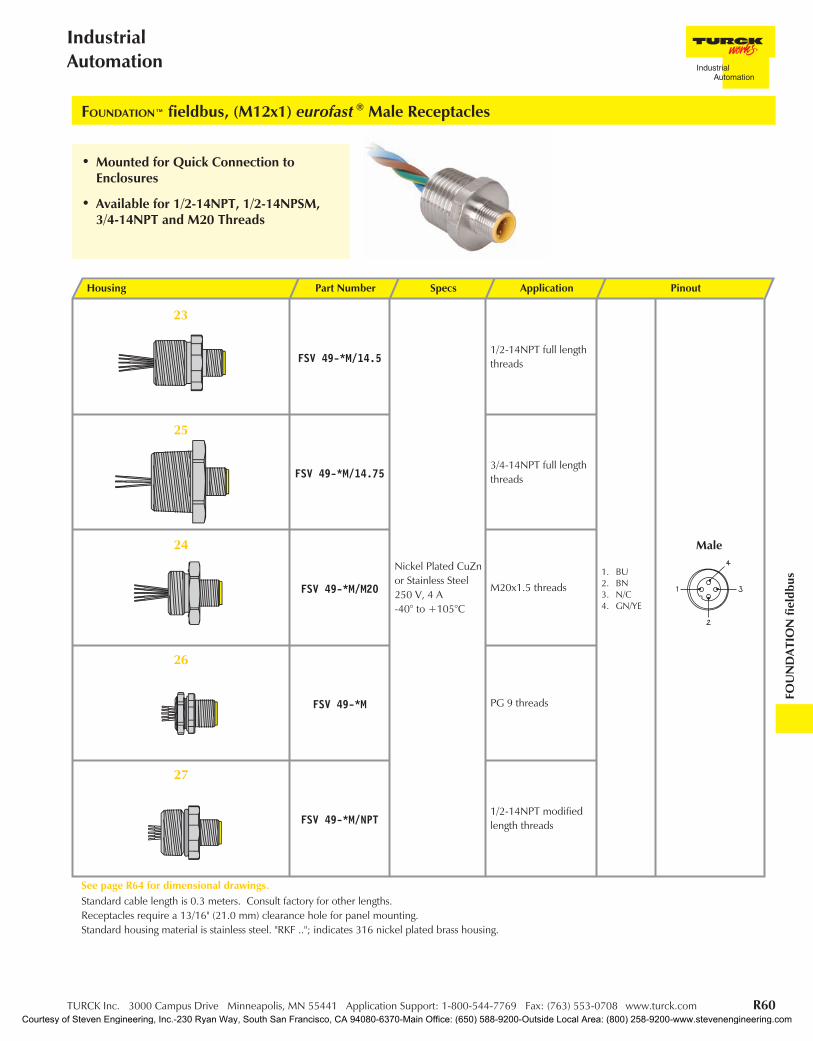
FOUNDATION™ fieldbus, (M12x1) eurofast ® Male Receptacles
• Mounted for Quick Connection toEnclosures
• Available for 1/2-14NPT, 1/2-14NPSM,3/4-14NPT and M20 Threads
27
Housing Part Number Specs Application Pinout
FSV 49-*M/14.5
Nickel Plated CuZnor Stainless Steel250 V, 4 A-40° to +105°C
1/2-14NPT full lengththreads
1. BU2. BN3. N/C4. GN/YE
FSV 49-*M/14.753/4-14NPT full lengththreads
FSV 49-*M/M20 M20x1.5 threads
FSV 49-*M PG 9 threads
FSV 49-*M/NPT1/2-14NPT modifiedlength threads
See page R64 for dimensional drawings.Standard cable length is 0.3 meters. Consult factory for other lengths.Receptacles require a 13/16" (21.0 mm) clearance hole for panel mounting.Standard housing material is stainless steel. "RKF .."; indicates 316 nickel plated brass housing.
26
24
25
23
Male
Courtesy of Steven Engineering, Inc.-230 Ryan Way, South San Francisco, CA 94080-6370-Main Office: (650) 588-9200-Outside Local Area: (800) 258-9200-www.stevenengineering.com

R61 TURCK Inc. 3000 Campus Drive Minneapolis, MN 55441 Application Support: 1-800-544-7769 Fax: (763) 553-0708 www.turck.com
TURCKNetwork Media Products
FOUNDATION™ fieldbus, (M12x1) eurofast ® Female Receptacles
• Mounted for Quick Connection toEnclosures
• Available for 1/2-14NPT, 1/2-14NPSM,3/4-14NPT and M20 Threads
Housing Part Number Specs Application Pinouts
FKV 49-*M/14.5
Nickel Plated CuZnor Stainless Steel250 V, 4 A-40° to +105°C
1/2-14NPT FullLength Threads
1. BU2. BN3. N/C4. GN/YE
FKV 49-*M/14.753/4-14NPT FullLength Threads
FKV 49-*M/M20 M20x1.5 Threads
FKV 49-*M PG 9 Threads
FKV 49-*M/NPT1/2-14NPTModified LengthThreads
See page R65 for dimensional drawings.Standard cable length is 0.3 meters. Consult factory for other lengths.Receptacles require a 13/16" (21.0 mm) clearance hole for panel mounting.Standard housing material is stainless steel. "RKF .."; "RKFV .." indicates 316 nickel plated brass housing.
31
32
28
30
29 Female
Courtesy of Steven Engineering, Inc.-230 Ryan Way, South San Francisco, CA 94080-6370-Main Office: (650) 588-9200-Outside Local Area: (800) 258-9200-www.stevenengineering.com
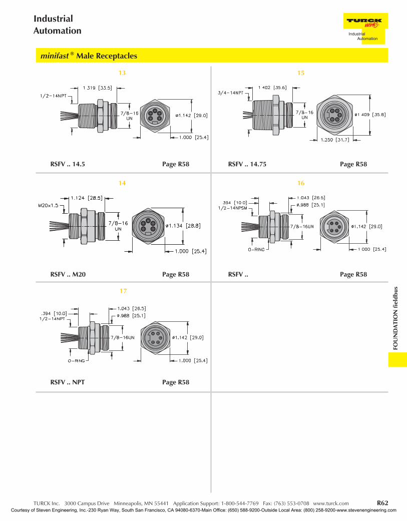
TURCK Inc. 3000 Campus Drive Minneapolis, MN 55441 Application Support: 1-800-544-7769 Fax: (763) 553-0708 www.turck.com R62
IndustrialAutomation
FOU
ND
ATIO
Nfie
ldbu
s17
RSFV .. NPT Page R58
14
RSFV .. M20 Page R58
16
RSFV .. Page R58
13
RSFV .. 14.5 Page R58
15
RSFV .. 14.75 Page R58
minifast ® Male Receptacles
Courtesy of Steven Engineering, Inc.-230 Ryan Way, South San Francisco, CA 94080-6370-Main Office: (650) 588-9200-Outside Local Area: (800) 258-9200-www.stevenengineering.com

R63 TURCK Inc. 3000 Campus Drive Minneapolis, MN 55441 Application Support: 1-800-544-7769 Fax: (763) 553-0708 www.turck.com
TURCKNetwork Media Products
19
RKFV .. M20 Page R59
21
RKFV .. Page R59
22
RKFV .. NPT Page R59
18
RKFV .. 14.5 Page R59
20
RKFV .. 14.75 Page R59
minifast ® Female Receptacles
Courtesy of Steven Engineering, Inc.-230 Ryan Way, South San Francisco, CA 94080-6370-Main Office: (650) 588-9200-Outside Local Area: (800) 258-9200-www.stevenengineering.com

TURCK Inc. 3000 Campus Drive Minneapolis, MN 55441 Application Support: 1-800-544-7769 Fax: (763) 553-0708 www.turck.com R64
IndustrialAutomation
FOU
ND
ATIO
Nfie
ldbu
s27
FSV .. NPT Page R60
24
FSV .. M20 Page R60
26
FSV .. Page R60
23
FSV .. 14.5 Page R60
25
FSV .. 14.75 Page R60
eurofast ® Male Receptacles
Courtesy of Steven Engineering, Inc.-230 Ryan Way, South San Francisco, CA 94080-6370-Main Office: (650) 588-9200-Outside Local Area: (800) 258-9200-www.stevenengineering.com
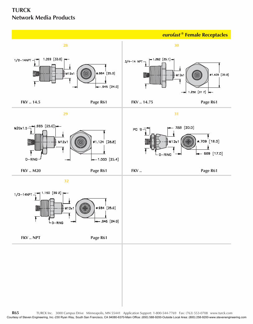
R65 TURCK Inc. 3000 Campus Drive Minneapolis, MN 55441 Application Support: 1-800-544-7769 Fax: (763) 553-0708 www.turck.com
TURCKNetwork Media Products
eurofast ® Female Receptacleseurofast ® Female Receptacleseurofast ® Female Receptacleseurofast ® Female Receptacles
29
FKV .. M20 Page R61
31
FKV .. Page R61
32
FKV .. NPT Page R61
28
FKV .. 14.5 Page R61
30
FKV .. 14.75 Page R61
eurofast ® Female Receptacles
Courtesy of Steven Engineering, Inc.-230 Ryan Way, South San Francisco, CA 94080-6370-Main Office: (650) 588-9200-Outside Local Area: (800) 258-9200-www.stevenengineering.com
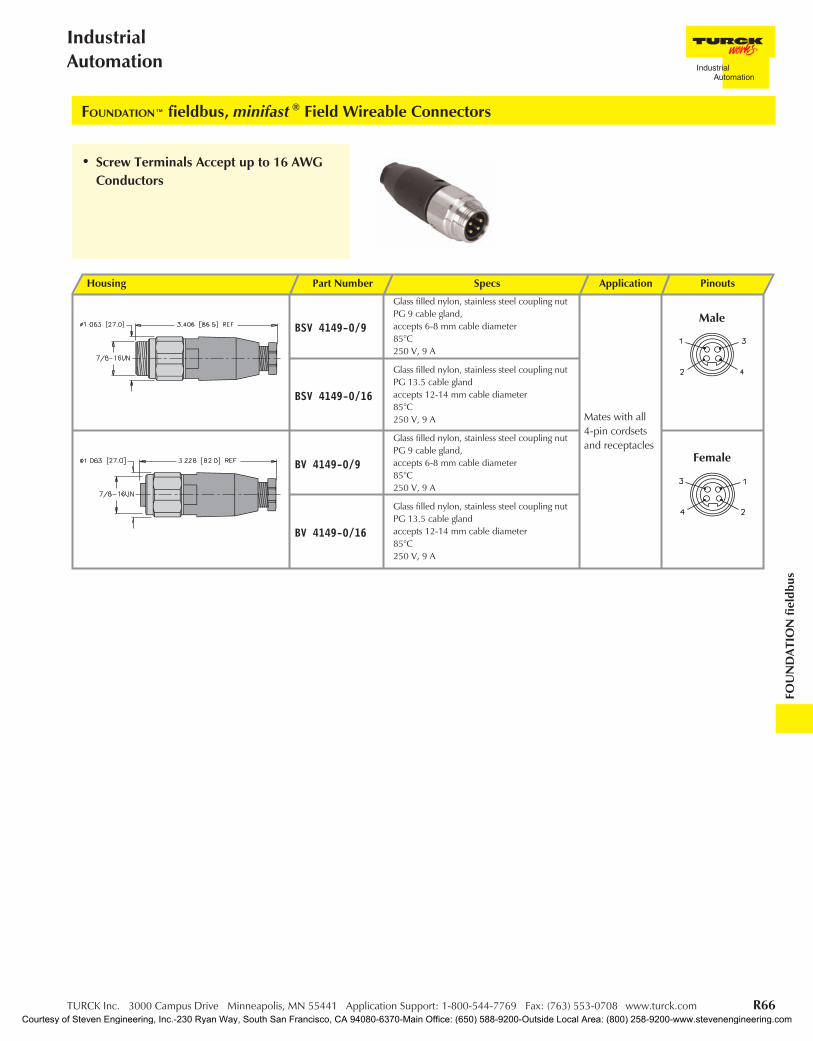
TURCK Inc. 3000 Campus Drive Minneapolis, MN 55441 Application Support: 1-800-544-7769 Fax: (763) 553-0708 www.turck.com R66
IndustrialAutomation
FOU
ND
ATIO
Nfie
ldbu
s
FOUNDATION™ fieldbus, minifast ® Field Wireable Connectors
Housing Part Number Specs Application Pinouts
BSV 4149-0/9
Glass filled nylon, stainless steel coupling nutPG 9 cable gland,accepts 6-8 mm cable diameter85°C250 V, 9 A
Mates with all4-pin cordsetsand receptacles
BSV 4149-0/16
Glass filled nylon, stainless steel coupling nutPG 13.5 cable glandaccepts 12-14 mm cable diameter85°C250 V, 9 A
BV 4149-0/9
Glass filled nylon, stainless steel coupling nutPG 9 cable gland,accepts 6-8 mm cable diameter85°C250 V, 9 A
BV 4149-0/16
Glass filled nylon, stainless steel coupling nutPG 13.5 cable glandaccepts 12-14 mm cable diameter85°C250 V, 9 A
Male
Female
• Screw Terminals Accept up to 16 AWGConductors
Courtesy of Steven Engineering, Inc.-230 Ryan Way, South San Francisco, CA 94080-6370-Main Office: (650) 588-9200-Outside Local Area: (800) 258-9200-www.stevenengineering.com
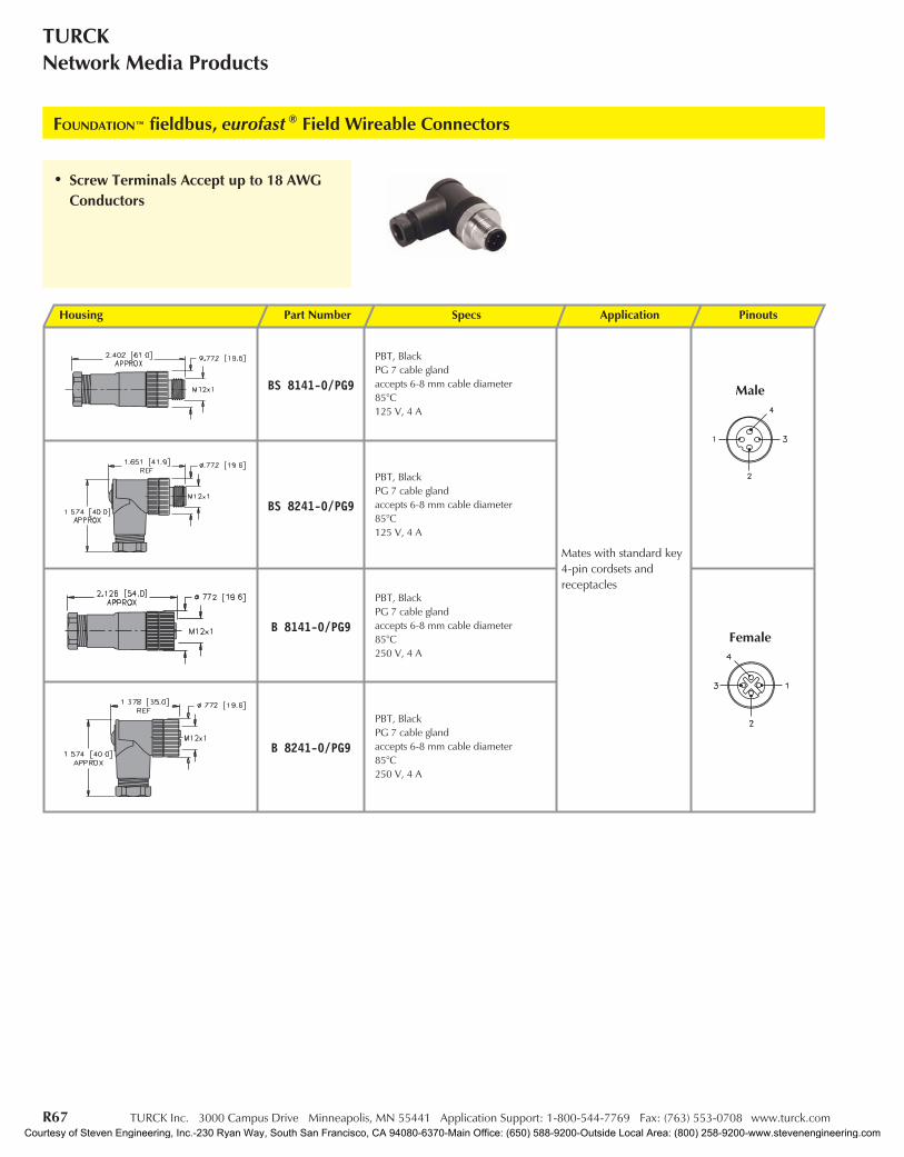
R67 TURCK Inc. 3000 Campus Drive Minneapolis, MN 55441 Application Support: 1-800-544-7769 Fax: (763) 553-0708 www.turck.com
TURCKNetwork Media Products
FOUNDATION™ fieldbus, eurofast ® Field Wireable Connectors
Housing Part Number Specs Application Pinouts
BS 8141-0/PG9
PBT, BlackPG 7 cable glandaccepts 6-8 mm cable diameter85°C125 V, 4 A
Mates with standard key4-pin cordsets andreceptacles
BS 8241-0/PG9
PBT, BlackPG 7 cable glandaccepts 6-8 mm cable diameter85°C125 V, 4 A
B 8141-0/PG9
PBT, BlackPG 7 cable glandaccepts 6-8 mm cable diameter85°C250 V, 4 A
B 8241-0/PG9
PBT, BlackPG 7 cable glandaccepts 6-8 mm cable diameter85°C250 V, 4 A
Female
Male
• Screw Terminals Accept up to 18 AWGConductors
Courtesy of Steven Engineering, Inc.-230 Ryan Way, South San Francisco, CA 94080-6370-Main Office: (650) 588-9200-Outside Local Area: (800) 258-9200-www.stevenengineering.com
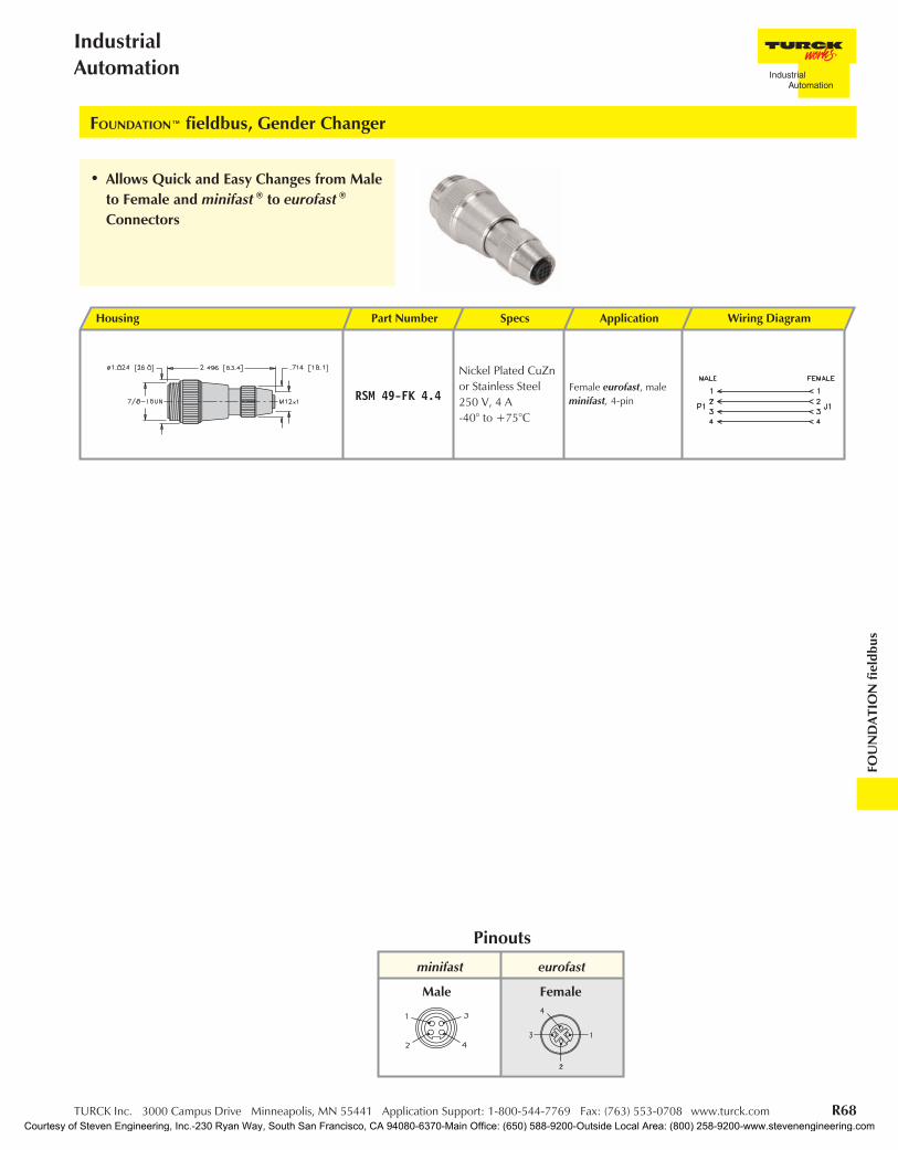
TURCK Inc. 3000 Campus Drive Minneapolis, MN 55441 Application Support: 1-800-544-7769 Fax: (763) 553-0708 www.turck.com R68
IndustrialAutomation
FOU
ND
ATIO
Nfie
ldbu
s
Housing Part Number Specs Application Wiring Diagram
RSM 49-FK 4.4
Nickel Plated CuZnor Stainless Steel250 V, 4 A-40° to +75°C
Female eurofast, maleminifast, 4-pin
FOUNDATION™ fieldbus, Gender Changer
minifast eurofast
Pinouts
Male Female
• Allows Quick and Easy Changes from Maleto Female and minifast ® to eurofast ®
Connectors
Courtesy of Steven Engineering, Inc.-230 Ryan Way, South San Francisco, CA 94080-6370-Main Office: (650) 588-9200-Outside Local Area: (800) 258-9200-www.stevenengineering.com
Related Documents