Turbine Bypass Valve Technology and Applications

Welcome message from author
This document is posted to help you gain knowledge. Please leave a comment to let me know what you think about it! Share it to your friends and learn new things together.
Transcript

Turbine Bypass Valve
Technology and
Applications
The turbine bypass system is a very important component of power stations, and of a difficult
service too. Although it does not operate continuously, when it is required to operate it has to
be fast and reliable. Its main job is called steam conditioning. It means pressure reduction and
desuperheating of steam that has been produced by the boiler but, due to transient or
unexpected conditions, can not flow through the turbine.
The percentage of total steam handled by the turbine bypass system depends on plant design
philosophy. Capacity usually ranges between 30% up to 100% of the maximum continuous rating
(MCR) boiler steam flow.
The high pressure turbine bypass system provides an alternate flow path at the high pressure
side of the turbine, taking the steam from the turbine inlet to the reheater inlet section. This
bypass system permits stable operation of the boiler when the turbine trips off line or during
start-up operations. Steam flowing through the high pressure bypass control valve is throttled
and cooled to a temperature slightly above the HP turbine exhaust temperature, by spraying
feed water at the outlet of the bypass control valve. This flow is then combined with high
pressure exhaust steam and passes through the reheater.
The low pressure turbine bypass system presents a flow path around the LP turbine, taking
steam from the reheater outlet and conditioning it to be fed into the condenser. For condenser
protection, high pressure and temperature drops are taken by valve throttling and by addition of
large amounts of desuperheating spray water, preventing that superheated steam reaches the
condenser.
Design Considerations
Turbine Bypass System Valves: The purpose of the turbine bypass system is
to rapidly dump steam to the condenser in the event of a turbine trip, or to
bypass the turbine during startup or commissioning. Multiple, staged valves
are used to provide controlled bypass functionality.
Various turbine bypass valving schemes are used, depending on the system
design. The bypass system is designed to operate before the pressure safety
valves lift off their seats and dump steam to the atmosphere with
consequent substantial loss of boiler water. This sometimes is reflected in a
bypass system capable of dumping 100% of full-load steam; however, in
some designs, a 100% bypass capability is used for the HP turbine and a
lower rated capacity in the range of 50% to 70% for the LP turbines. Bypass
capacities below 40% of full-load capacity are not recommended. The
Siemens Reference Power Plant includes 2 X 50% bypass valve stations for
the HP Turbine Bypass, and 1 X 60% bypass valve station for the LP Turbine
Bypass.
Siemens 2 x 50% for HP and 1 x 60% for LP

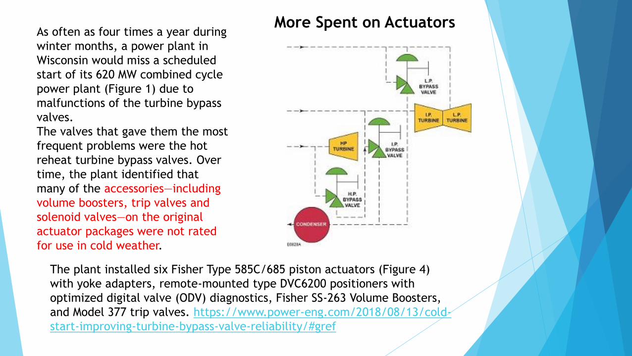
As often as four times a year during
winter months, a power plant in
Wisconsin would miss a scheduled
start of its 620 MW combined cycle
power plant (Figure 1) due to
malfunctions of the turbine bypass
valves.
The valves that gave them the most
frequent problems were the hot
reheat turbine bypass valves. Over
time, the plant identified that
many of the accessories—including
volume boosters, trip valves and
solenoid valves—on the original
actuator packages were not rated
for use in cold weather.
The plant installed six Fisher Type 585C/685 piston actuators (Figure 4)
with yoke adapters, remote-mounted type DVC6200 positioners with
optimized digital valve (ODV) diagnostics, Fisher SS-263 Volume Boosters,
and Model 377 trip valves. https://www.power-eng.com/2018/08/13/cold-
start-improving-turbine-bypass-valve-reliability/#gref
More Spent on Actuators

A few years ago, the high pressure
(HP) feedwater control valves and
manually operated HP and reheat
superheater drain valves with
maximum ΔPs of 115 bar failed at
AES’s 688 MW Medway Power Ltd.,
plant in the UK. The failure of these
drilled-hole, cage-guided control
valves was due to excessive trim
exit kinetic energy (or velocity head
– Hv). The replacement valve trim
used takes full advantage of
multistage-pressure reduction
technology to severely limit this Hv.
Since then, AES has used this design technology in critical combined cycle, turbine bypass
systems in most of its new power plants. In fact in the last five years or so, this critical-
service, multistage pressure-reduction technology with severely limited Hv has been
utilized internationally in five AES combined cycle plants ranging from the 230 MW AES
Barry Power Plant in Wales up to this 705 MW AES Ironwood power plant in Pennsylvania.
Improved Trim Design

The turbine-bypass system at AES Ironwood
consists of two, 100 x 250 mm HP steam-bypass-
to-cold-reheat valves, two 400 x 400 mm low
pressure (LP) steam-bypass-to-condenser, and
two 640 x 889 mm hot-reheat-steam-bypass
valves to the condenser, with an associated
desuperheating spraywater control valve for each
steam bypass valve.
The HP bypass-to-cold-reheat valves are designed
for steam flows up to 70 kg/s at maximum inlet
pressures of 130 bar[a] and ΔPs of 115 bar at
570°C. The LP bypass-to-condenser valves are
designed for steam flows up to 11 kg/s at
maximum inlet pressures of 4 bar[a] and ΔPs of 3
bar at 27°C. The hot reheat bypass-to-condenser
valves are designed for flows up to 95 kg/s at
maximum inlet pressures of 30 bar[a] and ΔPs of
29 bar at 570°C
Specific Valve Specifications


Valve Life is Shorter
than Anticipated


A new phenomenon appeared in the HP steam-turbine bypass circuit: Erosion of the pressure control valve cage, disc, and seat by wet steam and water. HP bypass-valve erosion. Abnormal seat,
plug, and cage erosion in bypass pressure control valves
has become common regardless of valve manufacturer,
“caused by passing wet steam and/or water through the
PCV. As damage progresses, superheated steam can leak
through and overheat the downstream carbon steel
pipe.”
Barry Dooley, Structural Integrity Associates Inc, and
Bob Anderson, Competitive Power Resources Corp
(CPR).
Have compiled in an extensive report, “Trends in HRSG
Reliability—a 10-Year Review,” as of 2019
Turbine Bypass Valve Life in GTCC Plants is less than in Coal Fired Plants
due to Cycling and Flow Accelerated Corrosion and Other Problems

High-delta-p Investigation Identifies HRH Piping CracksTenaska Central Alabama Generating Station
Tenaska Alabama II Partners LP
885-MW, gas-fired, 3 × 1 combined cycle located in Billingsley, Ala
Plant manager: Robert Threlkeld
Key project participants: Brian Pillittere, plant engineer; Alan Foether, LCRO; Cecil Boatwright,
operations manager
Challenge.
Plant personnel found that the steam turbine experiencing higher than normal exhaust backpressure. The operators
noticed that the backpressure dropped whenever the hot reheat (HRH) bypass valves were opened.
Solution.
The LCRO came up with the idea to perform a test to determine the relationship between the HRH bypass-valve
operation and the turbine-exhaust backpressure. During a plant startup, the steam pressure was increased in the
HRH piping and steam was observed coming through the insulation downstream of the Unit 3 HRH bypass valve.
The pipe insulation was removed and it was determined that the steam was coming from a crack in the weld that
connects the HRH bypass valve to the downstream P91 piping. The valve was closed and the sound of air being
sucked into the crack was heard.
A plant outage was taken to grind out the cracks and make weld repairs. The repaired areas will be inspected
during future scheduled outages. In addition, manual block valves will be installed downstream of the HRH bypass
valves in 2011 to allow repairs to the valves and piping to be made without requiring a full plant outage.
Results.
Steam-turbine backpressure has since returned to normal. Backpressure is monitored regularly during plant
operation using an Excel® model that compares the actual backpressure to the condenser manufacturer’s design
backpressure curves based on the circulating-water temperature and condenser heat load.


Although many OEMs are using more-erosion-resistant designs and materials, presenters representing leading valve manufacturers stressed that “no PCV design can tolerate wet steam.” Newer materials and designs will only slow the wet-steam erosion process. Severe damage can result within one year in cycling units. Mechanisms of damage by wet steam were explained in detail, with visual examples and specific case studies (both existing and new units).
A workshop on optimization of steam-turbine bypass systems at the
2018 meeting of the Australasian Boiler and HRSG Users Group, led
by Bob Anderson, Competitive Power Resources Corp, covered the
arrangement, purpose, and methods for operating and maintaining
this equipment.
Vibrant discussion followed presentations by Anderson, Justin
Goodwin of Emerson/Fisher, Ory Selzer of IMI CCI, and Sanjay
Sherikar of Nihon Koso Co Ltd.

Due to the severe thermal cycling over operation, a fatigue failure can
occur in the valve body of the bypass valve. So, it is necessary to
estimate the fatigue life of the given bypass valve for the operating
conditions like cold start, warm start & hot start. What are the operating
conditions of these valves. Usually three generic operating conditions are
found for a power plant 1. Cold start (>72hrs of plant shutdown) 2. Warm
start (<=45hrs of shutdown) 3. Hot start (<=8hrs of shutdown) Among
these three conditions, hot start is the most prevalent & necessary
operating condition. Fatigue life requirements can be from 5000 cycles
to 15000 cycles & varies for different plants
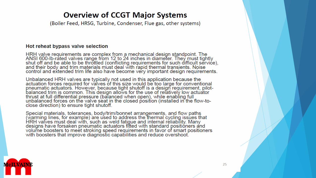
Essential characteristics of bypass valve
• Resistance to thermal shock and fatigue: The Bypass Valve will be
subject to severe thermal shock (>200degC). Valve body and trim must
be designed to assure reliable operation.
• Maximizing Power Output and reduced Maintenance: Repeatable seat
tightness is required to prevent steam leakage that can otherwise be
used to generate electricity and therefore revenue. Excessive seat
leakage also results in excessive maintenance and plant shutdown
• https://www.irjet.net/archives/V5/i3/IRJET-V5I3806.pdf

The gas turbine (GT) at a 1 × 1 single-shaft combined-cycle plant designed for
flexible operation has a staged combustion system that permits emissions
compliance and a relatively good heat rate down to low loads. The HRSG is a
three-pressure, reheat, horizontal-gas-flow unit equipped with only HP (high
pressure, main steam) and RH (reheat steam) terminal attemperators. There is
no duct burner or SCR.
Repeated severe water erosion damage to the HP bypass pressure control valve
(PCV) caused the PVC to leak in combined-cycle service, requiring multiple
repairs at significant unbudgeted costs and involving long forced outages.
Corrective actions:
Delay opening the HP-bypass PCV until the main-steam temperature
measured downstream of the bypass tee increases to 20-deg-C above
Tsat.
Repair the leaking HP attemperator spray and block valves.
Leave the main-steam-pipe warming drain open during open-cycle
operation. This may require modulating the drain valve’s position to limit
steam flow while avoiding condensation in the deadheaded section of
pipe.
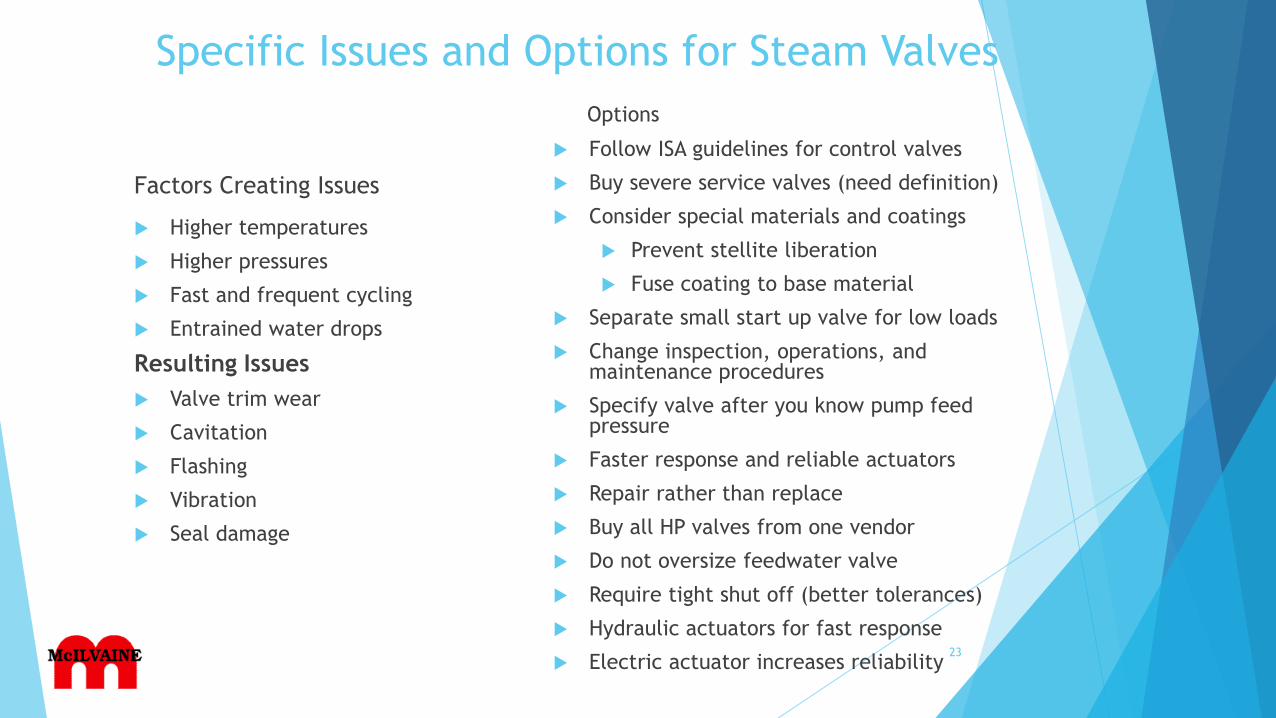
Specific Issues and Options for Steam Valves
Factors Creating Issues
Higher temperatures
Higher pressures
Fast and frequent cycling
Entrained water drops
Resulting Issues
Valve trim wear
Cavitation
Flashing
Vibration
Seal damage
Options
Follow ISA guidelines for control valves
Buy severe service valves (need definition)
Consider special materials and coatings
Prevent stellite liberation
Fuse coating to base material
Separate small start up valve for low loads
Change inspection, operations, and maintenance procedures
Specify valve after you know pump feed pressure
Faster response and reliable actuators
Repair rather than replace
Buy all HP valves from one vendor
Do not oversize feedwater valve
Require tight shut off (better tolerances)
Hydraulic actuators for fast response
Electric actuator increases reliability23

Background Documents
in Intelligence System

Vector and Wellheads Engineering Turbine Bypass System
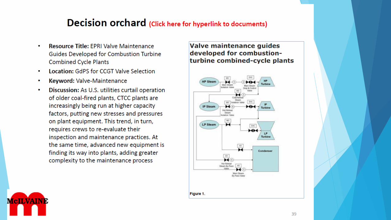
This paper has a good flow diagram with valve locations. The turbine bypass
system is a very important component in power stations, and of a difficult service
too Revision Date: 9/9/2019
Valvtechnologies Turbine Bypass System
The steam turbine bypass system will allow the operator to keep the gas turbine
and the heat recovery system generator (HRSG) on-line in the event of a steam
turbine trip or to facilitate faster start-ups of the CT and HRSG.
Revision Date: 9/9/2019
Proper Steam Bypass System Design Avoids Steam Turbine Overheating
The steam bypass system is generally used during the following modes of
operation: start-up and shutdown, steam turbine trip, steam turbine no-load or
low-load operation, and simple-cycle operation. On start-up, the isolation of the
CTG/HRSG from the STG allows the CTG to be placed on load without delay and
well before the heat-up and roll-off of the STG. In addition, a faster start-up of
the STG is possible since the bypass system provides the capability of close
temperature matching between the steam inlet temperature and the steam
turbine metal temperature.
Revision Date: 9/9/2019
Related Documents