FLUID MECHANICS AND MACHINERY

Turbine - A neat differentiation
Jul 13, 2015
Welcome message from author
This document is posted to help you gain knowledge. Please leave a comment to let me know what you think about it! Share it to your friends and learn new things together.
Transcript

FLUID MECHANICS AND MACHINERY

TURBINE

What is a TURBINE???A turbine is a rotary mechanical
device that extracts energy from
a fluid flow and converts it into
useful work.
A turbine is a turbomachine with at
least one moving part called a rotor
assembly, which is a shaft or drum
with blades attached.
Moving fluid acts on the blades so
that they move and impart rotational
energy to the rotor.

• Credit for invention of the steam turbine is given
both to the British engineer Sir Charles
Parsons (1854–1931), for invention of the reaction
turbine and to Swedish engineer Gustaf de
Laval (1845–1913), for invention of the impulse
turbine
• The word "turbine" was coined in 1822 by the French
mining engineer Claude Burdin from the Latin turbo,
or vortex
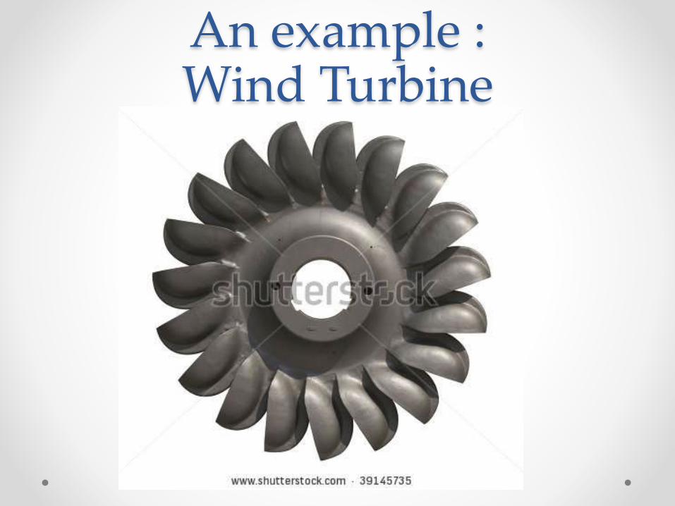
An example :Wind Turbine

WORKING PRINCIPLE:• The working principle is very much simple.
• When the fluid strikes the blades of the turbine, the
blades are displaced, which produces rotational
energy.
• When the turbine shaft is directly coupled to an
electric generator , mechanical energy is
converted into electrical energy.
• This electrical power is known as hydroelectric
power.

TYPES:According to the action of the
water flowing
1.Impulse turbine e.g Pelton
Wheel
2.Reaction turbine e.g Francis
turbine, Kaplan turbine.
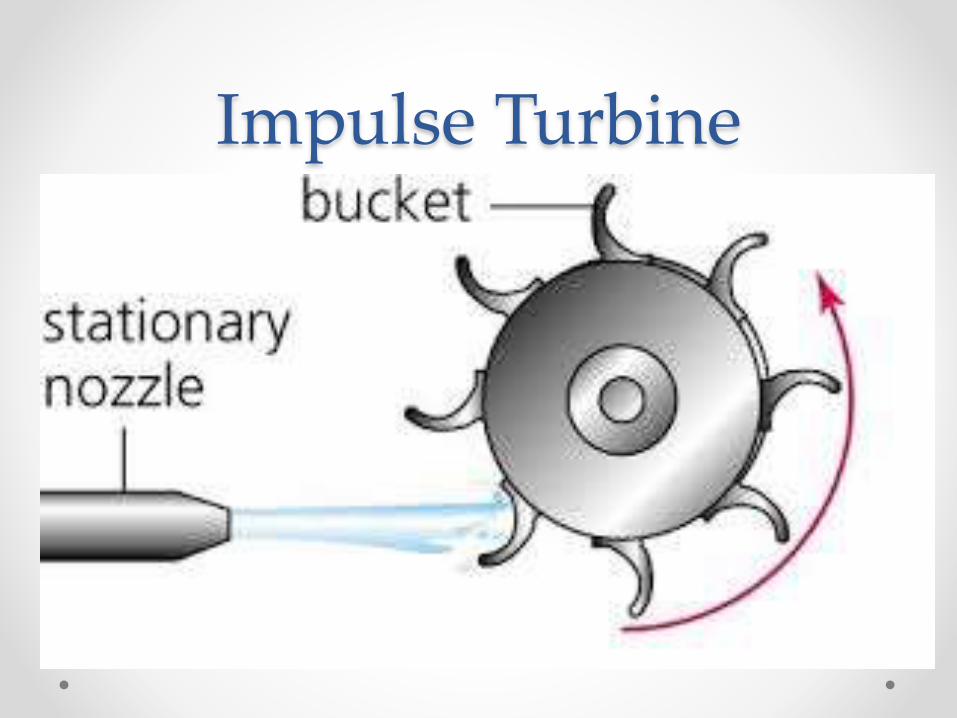
Impulse Turbine
Impulse Turbine• In an impulse turbine the potential energy, or the
head of water, is first converted into kinetic
energy by discharging water through a carefully
shaped nozzle. The jet, discharged into air, is
directed onto curved buckets fixed on the
periphery of the runner to extract the water energy
and convert it to useful work.

Reaction Turbine

Reaction Turbine• In a reaction turbine, forces driving the rotor are
achieved by the reaction of an accelerating water
flow in the runner while the pressure drops. The
reaction principle can be observed in a rotary lawn
sprinkler where the emerging jet drives the rotor in
the opposite direction.

Pelton Wheel

Pelton Wheel• It was invented by Lester Allan Pelton in the 1870s.
• Nozzles direct forceful, high-speed streams of water
against a rotary series of spoon-shaped buckets,
also known as impulse blades, which are mounted
around the circumferential rim of a drive wheel—
also called a runner

Applications• Pelton wheels are the preferred turbine for hydro-
power, when the available water source has
relatively high hydraulic head at low flow rates,
where the Pelton wheel is most efficient.
• Pelton wheels are made in all sizes.
• There exist multi-ton Pelton wheels mounted on
vertical oil pad bearings in hydroelectric plants.

Francis Turbine
Francis Turbine• The Francis turbine is a type of water turbine that
was developed by James B. Francis in Lowell,
Massachusetts.
• The Francis turbine is a type of reaction turbine, a
category of turbine in which the working fluid
comes to the turbine under immense pressure and
the energy is extracted by the turbine blades from
the working fluid

• . A part of the energy is given up by the fluid
because of pressure changes occurring in the
blades of the turbine, quantified by the expression
of Degree of reaction, while the remaining part of
the energy is extracted by the volute casing of the
turbine. At the exit, water acts on the spinning cup-
shaped runner features, leaving at low velocity and
low swirl with very little kinetic or potential
energy left. The turbine's exit tube is shaped to help
decelerate the water flow and recover the
pressure.
Application• Francis type units cover a head range from 40 to
600 m (130 to 2,000 ft), and their connected generator output power varies from just a few kilowatts up to 800 MW.
• Large Francis turbines are individually designed for each site to operate with the given water supply and water head at the highest possible efficiency, typically over 90%.
• In addition to electrical production, they may also be used for pumped storage, where a reservoir is filled by the turbine (acting as a pump) driven by the generator acting as a large electrical motor during periods of low power demand, and then reversed and used to generate power during peak demand
Kaplan Turbine

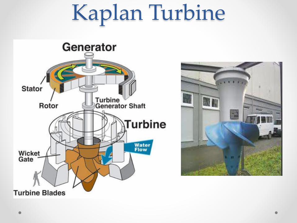
Kaplan Turbine• The Kaplan turbine is a propeller-type water
turbine which has adjustable blades. It was
developed in 1913 by the Austrian professor Viktor
Kaplan, who combined automatically adjusted
propeller blades with automatically adjusted wicket
gates to achieve efficiency over a wide range of
flow and water level.

• The Kaplan turbine is an inward
flow reaction turbine, which means that the working
fluid changes pressure as it moves through the
turbine and gives up its energy. Power is recovered
from both the hydrostatic head and from the kinetic
energy of the flowing water. The design combines
features of radial and axial turbines.
• The inlet is a scroll-shaped tube that wraps around
the turbine's wicket gate. Water is directed
tangentially through the wicket gate and spirals on
to a propeller shaped runner, causing it to spin.
• The outlet is a specially shaped draft tube that helps
decelerate the water and recover kinetic energy.
Applications• Kaplan turbines are widely used throughout the
world for electrical power production. They cover the lowest head hydro sites and are especially suited for high flow conditions.
• Inexpensive micro turbines on the Kaplan turbine model are manufactured for individual power production with as little as two feet of head.
• Large Kaplan turbines are individually designed for each site to operate at the highest possible efficiency, typically over 90%. They are very expensive to design, manufacture and install, but operate for decades.
Related Documents