Tuning into a Radio Station Tuning into stations automatically 1. Press TUNER on the main unit several times to select either "AM" or "FM". 2. Press TUNING MODE so that the "AUTO" indicator on the display lights. 3. Press TUNING to start automatic tuning. Searching automatically stops when a station is found. When tuned into a radio station, the " TUNED " indicator on the display lights. If FM stereo broadcasting is tuned, the "FM STEREO" indicator lights. No sound is output while the " TUNED " indicator is off. When the signal from an FM radio station is weak: Radio wave may be weak depending on the building structure and environmental conditions. In that case, manually tune into the radio station of your choice by referring to the next section. Tuning into stations manually AM/FM Radio Receiving Function

Welcome message from author
This document is posted to help you gain knowledge. Please leave a comment to let me know what you think about it! Share it to your friends and learn new things together.
Transcript
Tuning into a Radio Station
Tuning into stations automatically
1. Press TUNER on the main unit several times to select either "AM" or"FM".
2. Press TUNING MODE so that the "AUTO" indicator on the display lights.
3. Press TUNING to start automatic tuning. Searching automatically stops when a station is found. When tuned
into a radio station, the " TUNED " indicator on the display lights. IfFM stereo broadcasting is tuned, the "FM STEREO" indicator lights.
No sound is output while the " TUNED " indicator is off.
When the signal from an FM radio station is weak: Radio wave may beweak depending on the building structure and environmental conditions. Inthat case, manually tune into the radio station of your choice by referring tothe next section.
Tuning into stations manually
AM/FM Radio Receiving Function

1. Press TUNER on the main unit several times to select either "AM" or"FM".
2. Press TUNING MODE so that the "AUTO" indicator on the display goesoff.
3. Press TUNING to select the desired radio station. The frequency changes by 1 step each time you press the button. The
frequency changes continuously if the button is held down and stopswhen the button is released. Tune by looking at the display.
To return the display to "AUTO": Press TUNING MODE on the main unitagain. A station is automatically tuned. Normally "AUTO" should bedisplayed.
Tuning into stations by frequency
It allows you to directly enter the frequency of the radio station you want tolisten to.
1. Press TUNER on the remote controller several times to select either "AM"or "FM".
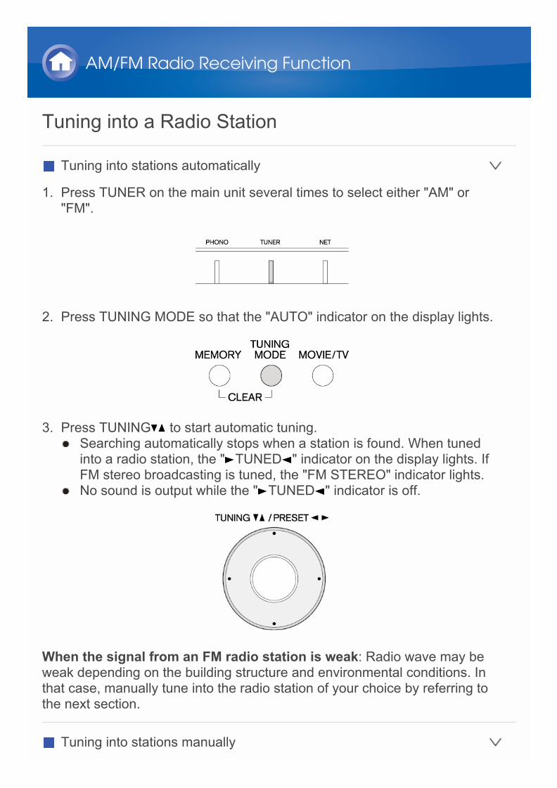
2. Press D.TUN.
3. Using the number buttons, enter the frequency of the radio station within8 seconds. To enter 87.5 (FM), for example, press 8, 7, 5, or 8, 7, 5, 0. If you
entered a wrong number, press D.TUN and enter a correct one.
Registering an AM/FM Radio StationIt allows you to register up to 40 of your favorite AM/FM radio stations.Registering radio stations in advance allows you to tune into your radiostation of choice directly.
Registering a Station
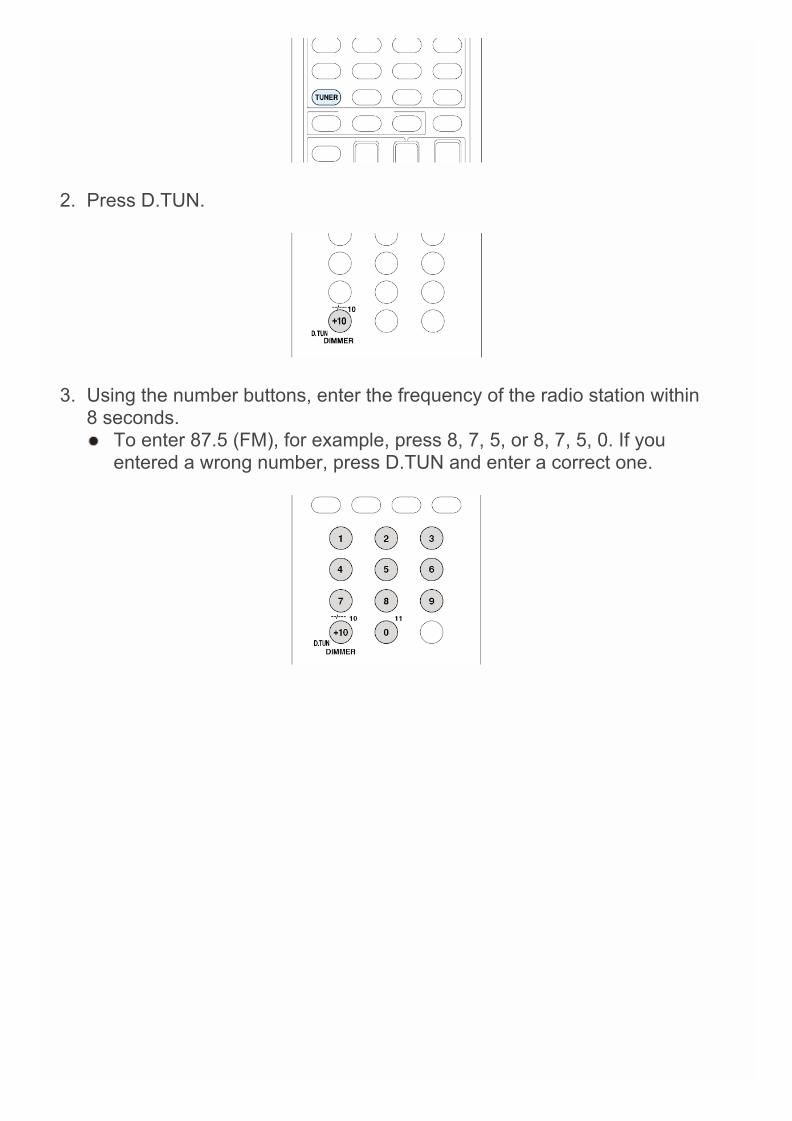
1. Tune into the AM/FM radio station you want to register.2. Press MEMORY on the unit so that the preset number on the display
flashes.
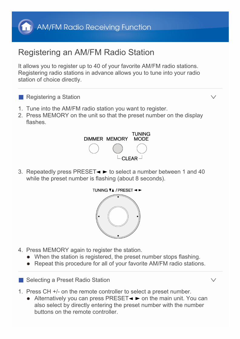
3. Repeatedly press PRESET to select a number between 1 and 40while the preset number is flashing (about 8 seconds).
4. Press MEMORY again to register the station. When the station is registered, the preset number stops flashing. Repeat this procedure for all of your favorite AM/FM radio stations.
Selecting a Preset Radio Station
1. Press CH +/- on the remote controller to select a preset number. Alternatively you can press PRESET on the main unit. You can
also select by directly entering the preset number with the numberbuttons on the remote controller.
AM/FM Radio Receiving Function

Deleting a Preset Radio Station
1. Press CH +/- on the remote controller to select the preset number todelete.
2. Press and hold MEMORY on the main unit and press TUNING MODE todelete the preset number. When deleted, the number on the display goes off.
Using RDS (European and Asian models)RDS stands for Radio Data System and is a method of transmitting data inFM radio signals. RDS works only in areas where RDS broadcasts are available. In some cases, the text information appeared on the display is not
identical to the content transmitted by the RDS station. Furthermore,unexpected characters may be displayed when the unit receivesunsupported characters. However, this is not a malfunction.
If the signal from an RDS station is weak, the RDS data may be displayedcontinuously or not at all.
PS (Program Service): Tuning into a radio station distributing ProgramService information displays the radio station name. Pressing DISPLAYdisplays the frequency for 3 seconds.
RT (Radio Text): Tuning into a radio station transmitting Radio Textinformation displays text on the display of the unit.
PTY (Program Type): Allows you to search for RDS stations by programtype.
TP (Traffic Program): Allows you to search for radio stations transmittingtraffic information.
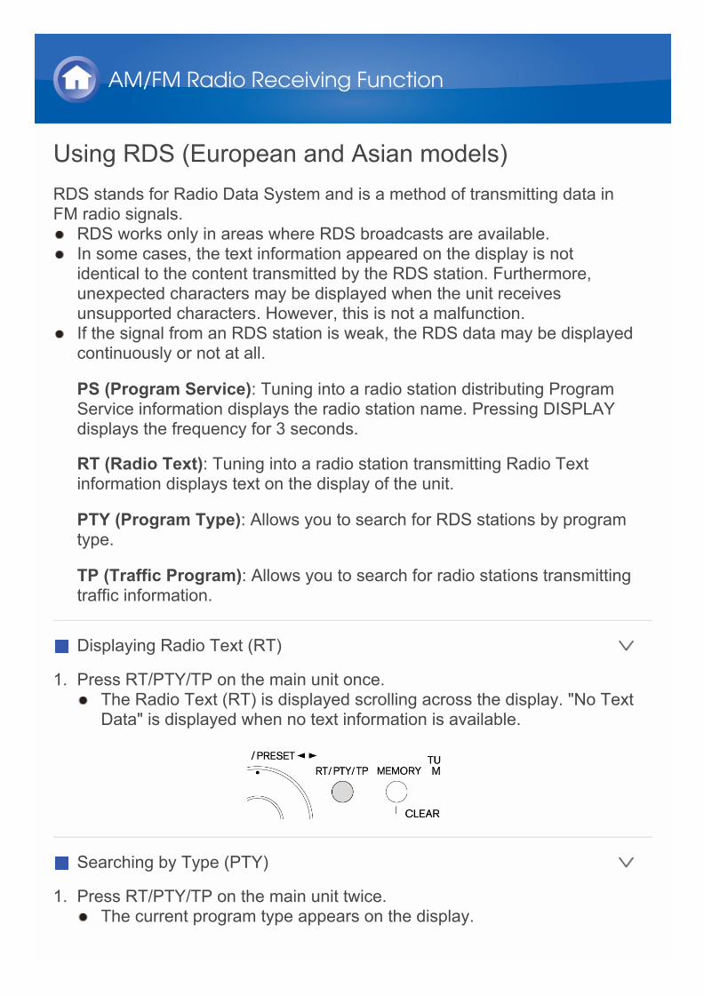
Displaying Radio Text (RT)
1. Press RT/PTY/TP on the main unit once. The Radio Text (RT) is displayed scrolling across the display. "No Text
Data" is displayed when no text information is available.
Searching by Type (PTY)
1. Press RT/PTY/TP on the main unit twice. The current program type appears on the display.
AM/FM Radio Receiving Function

2. Press PRESET to select the type of program to search for.
The following RDS station types are displayed: NoneNews (News reports)Affairs (Current affairs)Info (Information)SportEducate (Education)DramaCultureScience (Science and technology)VariedPop M (Pop music)Rock M (Rock music)Easy M (Middle of the road music)Light M (Light classics)Classics (Serious classics)Other M (Other music)WeatherFinanceChildren (Children’s programmes)Social (Social affairs)ReligionPhone InTravelLeisureJazz (Jazz music)Country (Country music)Nation M (National music)Oldies (Oldies music)Folk M (Folk music)Document (Documentary)

3. Press ENTER to search the radio stations of the selected type.
4. When such a radio station is found, the indication on the display flashes.Then, press ENTER again. If no stations are found, the message “Not Found” is displayed.
Listening to Traffic Information (TP)
1. Press RT/PTY/TP on the main unit three times. "[TP]" will be displayed if traffic information is transmitted by the radio
station you are tuned in. "TP" only is displayed if no traffic informationis available.
2. Press ENTER to search a radio station distributing traffic information.
3. When such a radio station is found, searching stops and playing trafficinformation starts. "Not Found" is displayed if no radio station distributing traffic
information is found.
Operation: You can set up by viewing the guidance displayed on the TVscreen. To display the guidance, you need to make HDMI connectionbetween the unit and TV. Select the item with the cursor buttons of theremote controller and press ENTER to confirm your selection. To return tothe previous screen, press RETURN.
Playing Back
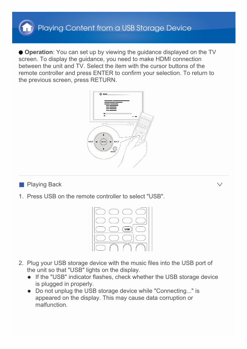
1. Press USB on the remote controller to select "USB".
2. Plug your USB storage device with the music files into the USB port ofthe unit so that "USB" lights on the display. If the "USB" indicator flashes, check whether the USB storage device
is plugged in properly. Do not unplug the USB storage device while "Connecting..." is
appeared on the display. This may cause data corruption ormalfunction.
Playing Content from a USB Storage Device

3. Press ENTER. The list of folders and music files on the USB storage device is
displayed. Select the folder with the cursors and press ENTER toconfirm your selection.
4. With the cursors, select the music file to play, and then press ENTER or to start playback.

About Internet RadioInternet radio, also called net radio, web radio or streaming radio, is an audioservice accessible at the websites of service providers who distribute musicand audio programs in digital format. There are numerous websites all overthe world, from terrestrial station, special station to personal website thatprovide such a service.The unit comes preset with Internet radio stations (*) such as TuneIn foryou to enjoy these services, just by connecting the unit to the Internet.
* Network services or contents may become unavailable if the serviceprovider terminates its service.
Listening to Internet Radio
TuneInWith more than 70,000 radio stations and 2 million on-demand programsregistered, TuneIn is a service where you can enjoy music, sports and newsfrom all over the world.
Operation: You can set up by viewing the guidance displayed on the TVscreen. To display the guidance, you need to make HDMI connectionbetween the unit and TV. Select the item with the cursor buttons of theremote controller and press ENTER to confirm your selection. To return tothe previous screen, press RETURN.
Playing Back
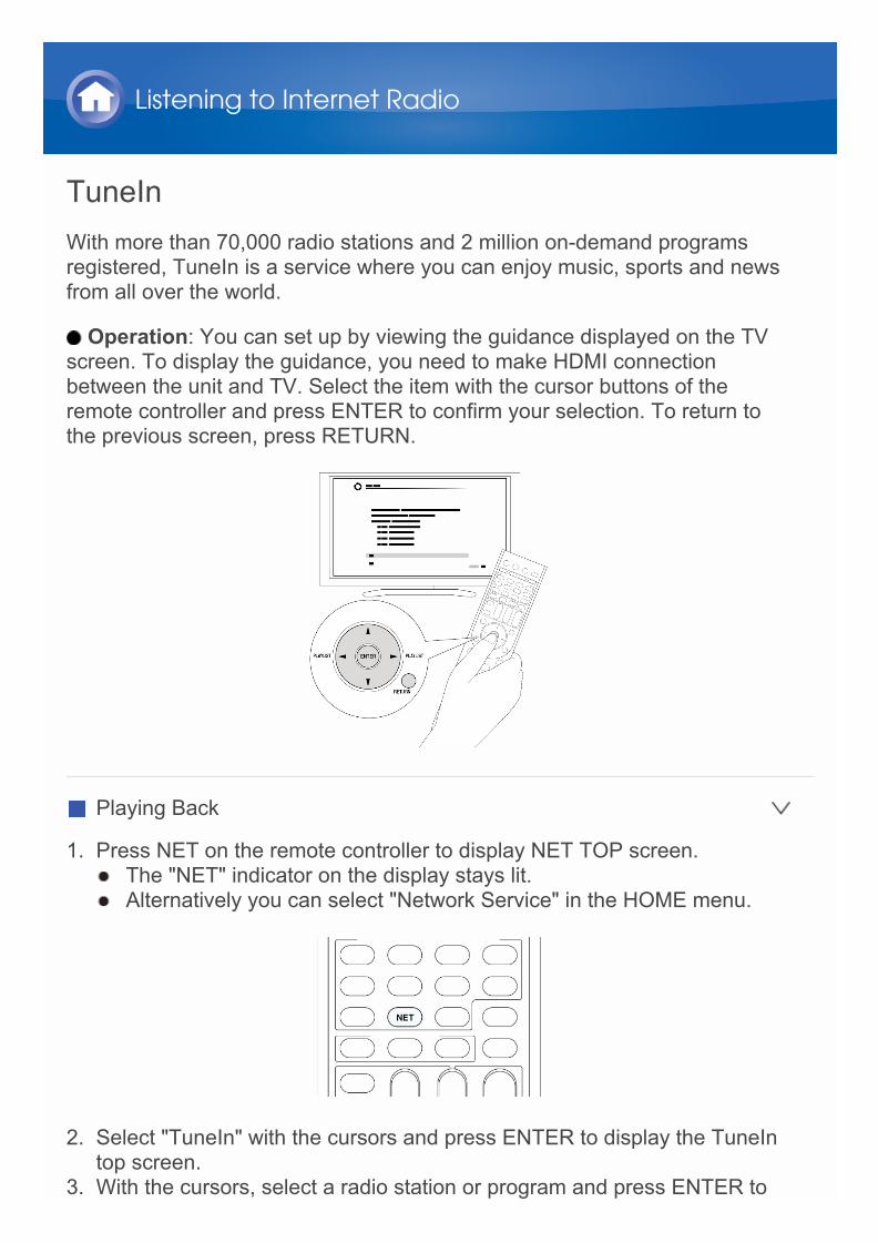
1. Press NET on the remote controller to display NET TOP screen. The "NET" indicator on the display stays lit. Alternatively you can select "Network Service" in the HOME menu.
2. Select "TuneIn" with the cursors and press ENTER to display the TuneIntop screen.
3. With the cursors, select a radio station or program and press ENTER to
Listening to Internet Radio
start playing.
Regarding the TuneIn Menu
To display the TuneIn menu, press MENU or ENTER while playing a radiostation. Selecting the corresponding menu item with the cursors andpressing ENTER allows you to perform the following operations:
Add to My Presets: Registers radio stations and programs in your "MyPresets" within TuneIn. This allows you to play registered radio stationsand programs with a simple operation. ("My Presets" is not displayed if itis empty.)
Remove from My Presets: Deletes a radio station or program from your"My Presets" within TuneIn.
Report a problem: Reports a problem or interactively solves a problemrelated to TuneIn.
View Schedule: Displays the radio station or program schedule.
Clear recents: Clears all radio stations and programs from the "Recents"within TuneIn. (This menu is displayed only when a radio station orprogram inside the "Recents" is being played.)
Add to My Favorites: Registers radio stations and programs in "MyFavorites" of "Network Service". This allows you to play registered radiostations and programs with a simple operation.
Regarding the TuneIn Account
Creating an account on the TuneIn website (tunein.com) and logging in itfrom the unit allows you to automatically add radio stations and programs toyour "My Presets" on the unit as you save them on the website .To display a radio station registered in "My Presets", you must log intoTuneIn from the unit. To log in, select "Login" - "I have a TuneIn account" inthe "TuneIn" top list on the unit, and then enter your user name andpassword. If you associate the device on My Page within the TuneIn website using
the registration code obtained by selecting "Login" - "Login with aregistration code" on the unit, you can log in without entering the username and password.

Pandora®–Getting Started (U.S. only)Pandora is a free, personalized Internet radio service that plays the musicyou know and helps you discover music you’ll love.
Operation: You can set up by viewing the guidance displayed on the TVscreen. To display the guidance, you need to make HDMI connectionbetween the unit and TV. Select the item with the cursor buttons of theremote controller and press ENTER to confirm your selection. To return tothe previous screen, press RETURN.
Playing Back
1. Press NET on the remote controller to display NET TOP screen. The "NET" indicator on the display stays lit. To display the NET TOP
screen, you can alternatively press HOME, select "Network Service"on the displayed HOME menu, and then press ENTER.
2. Select “Pandora” with the cursors, and then press ENTER.3. Use / to select “I have a Pandora Account” or “I’m new to Pandora” and
Listening to Internet Radio

then press ENTER.If you are new to Pandora select “I’m new to Pandora”. You will see anactivation code on your TV screen. Please write down this code. Go to anInternet connected computer and point your browser towww.pandora.com/onkyo. Enter your activation code and then follow theinstructions to create your Pandora account and your personalizedPandora stations. You can create your stations by entering your favoritetracks and artists when prompted. After you have created your accountand stations you can return to your Onkyo receiver and press ENTER tobegin listening to your personalized Pandora.If you have an existing Pandora account, you can add your Pandoraaccount to your Onkyo receiver by selecting “I have a Pandora Account”and logging in with your email and password. If you want to use multiple user accounts, see “Using Multiple
Accounts”. Login can be made from the “Users” screen.4. To play a station, use / to select the station from your station list, and
then press ENTER. Playback starts and the playback screen appears.
Create a New Station
Enter the name of a track, artist, or genre and Pandora will create a uniqueradio station for you based on the musical qualities of that track, artist, orgenre.
I like this track: Give a track “thumbs-up” and Pandora will play moremusic like it.
I don’t like this track: Give a track “thumbs-down” and Pandora will banthat track from the current station.
Why is this track playing?: Discover some of the musical attributes thatPandora uses to create your personal radio stations.
I’m tired of this track: If you are tired of a track, you can put the track tosleep and Pandora will not play it for one month.
Create station from this artist: Creates a radio station from this artist.
Create station from this track: Creates a radio station from this track.
Delete this station: This will permanently delete a station from yourPandora account. All of your thumbs feedback will be lost should youchoose to re-create the station with the same track or artist.
Rename this station: Lets you rename the current radio station.
Bookmark this artist: Pandora will bookmark your favorite artist for yourprofile on www.pandora.com.

Bookmark this track: Pandora will bookmark the current track and allowyou to buy them all from Amazon or iTunes in one step!
Add to My Favorites: Adds a station to My Favorites list.
PANDORA, the PANDORA logo, and the Pandora trade dress aretrademarks or registered trademarks of Pandora Media, Inc. Used withpermission.
SiriusXM Internet Radio (North American only)If you want to listen to the service, you must subscribe. To subscribe go towww.siriusxm.com/internetradio with your computer. When you subscribe,you will be provided with a username and password which has to be enteredinto the AV receiver. To use SiriusXM Internet Radio, you must have yourAV receiver connected to the Internet. Using the remote control, follow thesesteps:
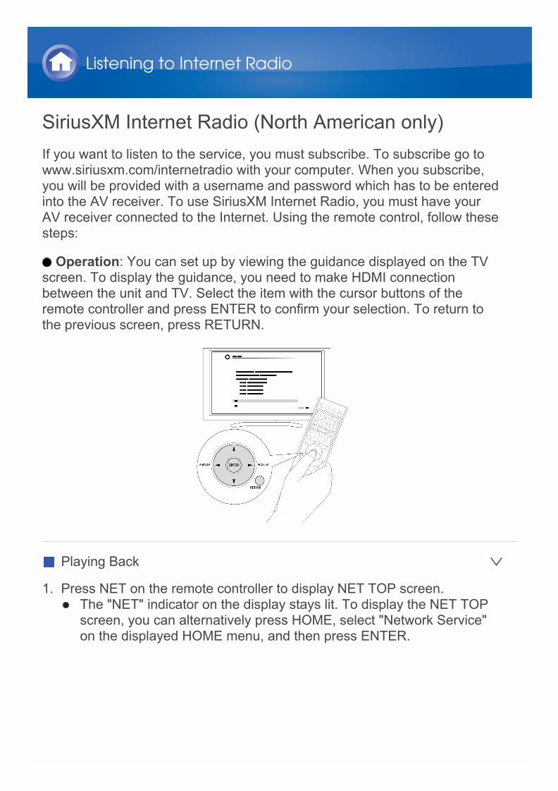
Operation: You can set up by viewing the guidance displayed on the TVscreen. To display the guidance, you need to make HDMI connectionbetween the unit and TV. Select the item with the cursor buttons of theremote controller and press ENTER to confirm your selection. To return tothe previous screen, press RETURN.
Playing Back
1. Press NET on the remote controller to display NET TOP screen. The "NET" indicator on the display stays lit. To display the NET TOP
screen, you can alternatively press HOME, select "Network Service"on the displayed HOME menu, and then press ENTER.
Listening to Internet Radio
2. Select “SiriusXM Internet Radio” with the cursors, and then pressENTER.
3. Select “Sign In”, and then press ENTER. If you have an existing SIRIUSaccount, you can sign in by selecting “Sign In”. Enter your user name andpassword in the next keyboard screen, or in Web Setup. If you don’t knowyour username or password, call Sirius XM at (888) 539-7474 forassistance. If you want to use multiple user accounts, see “Using Multiple
Accounts”. Login can be made from the “Users” screen.Using the keyboard screen1 Use / / / and ENTER to enter your user name and password.2 Select “OK”.3 Press ENTER. The “Confirm your entries” screen appears.4 Press ENTER. “Please wait...” appears and then “SiriusXM Internet
Radio” screen appears which displays the category available forselection.
4. Use / to select the category and then press ENTER. The channel list screen for the selected category appears.
5. Use / to select the desired channel and then press ENTER. The playback screen for the selected channel appears and you can
listen to SiriusXM Internet Radio. You can control the tracks with thebuttons on the remote control.Enabled buttons: , , ,
Add to My Favorites: Adds a channel to My Favorites list.
Add to Presets: Adds the currently playing station to presets list.
Delete from Presets: Deletes the currently playing station from presetslist.
SiriusXM Internet Radio subscriptions are sold separately and are governedby the Sirius Terms and Conditions (see www.sirius.com). Be sure to readthis agreement before you purchase your subscription.Sirius, XM and all related marks and logos are trademarks of Sirius XMRadio Inc. and its subsidiaries. All rights reserved.
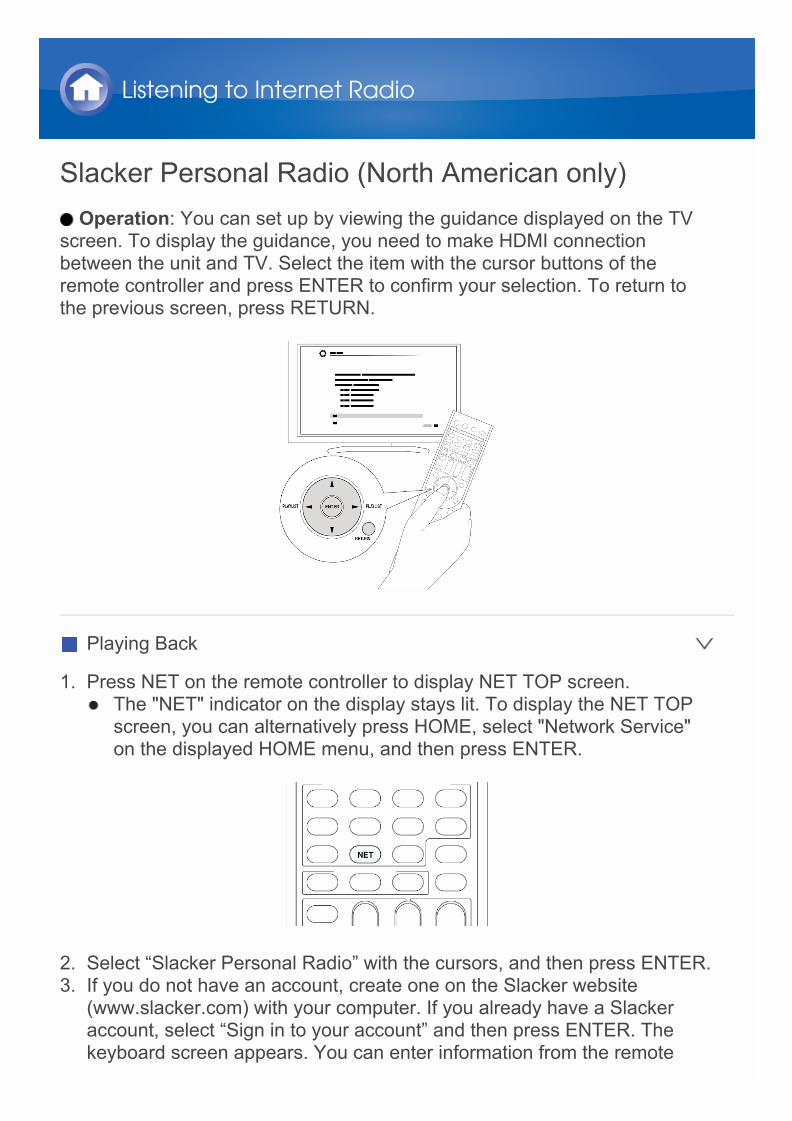
Slacker Personal Radio (North American only)Operation: You can set up by viewing the guidance displayed on the TV
screen. To display the guidance, you need to make HDMI connectionbetween the unit and TV. Select the item with the cursor buttons of theremote controller and press ENTER to confirm your selection. To return tothe previous screen, press RETURN.
Playing Back
1. Press NET on the remote controller to display NET TOP screen. The "NET" indicator on the display stays lit. To display the NET TOP
screen, you can alternatively press HOME, select "Network Service"on the displayed HOME menu, and then press ENTER.
2. Select “Slacker Personal Radio” with the cursors, and then press ENTER.3. If you do not have an account, create one on the Slacker website
(www.slacker.com) with your computer. If you already have a Slackeraccount, select “Sign in to your account” and then press ENTER. Thekeyboard screen appears. You can enter information from the remote
Listening to Internet Radio

control or the keys on the main unit.4. If there are no mistakes in the information you have entered, use / / /
to select “OK” then press ENTER. An account information confirmationscreen appears.
5. If you do not have an account, select “Access without Sign In” and pressENTER to use a restricted version of the service. Note that use will berestricted. If you want to use multiple user accounts, see “Using Multiple
Accounts”. Login can be made from the “Users” screen.6. Use / to select a menu item and then press ENTER.
To sign out, use / to select “Sign out” from this screen and then pressENTER.
7. Use / to select a station and then press ENTER or to start playbackfrom the station. The playback screen appears.
8. You can control the tracks with the buttons on the remote control.Enabled buttons: , , ,
Rate Song as Favorite: Stores information to server, making it morelikely that the song will be played again.
Ban Song: Stores information to server, making it less likely that thesong will be played again.
Ban Artist: Stores information to server, making it less likely that thesongs from this artist will be played again.
Mark Favorite: Adds the currently playing station to your favorites.
Unmark Favorite: Deletes the currently playing station from yourfavorites.
Add song to Library: Adds the currently playing track to your library.
Delete song from Library: Deletes the currently playing track from yourlibrary.
Add to My Favorites: Adds a station or song to My Favorites list.
Using Multiple Accounts: The AV receiver supports multiple user accounts,which means you can freely switch between several logins. After registeringuser accounts, login is performed from the “Users” screen.Press MENU while the Users screen is displayed. "Add new user", "Removethis user" menu appear. You can either store a new user account, or deletean existing one. Some of the services don’t allow the use of multiple user accounts. You can store up to 10 user accounts. To switch between accounts you must first log out from the current
account, and log in again on the "Users" screen.

Registering Other Internet RadiosTo listen to other Internet radio program, register the program in the "MyFavorites" list on the NET TOP screen as described below. The unit supportsInternet radio stations stored in the following formats: PLS (URL ending in.pls), M3U (URL ending in .m3u) and RSS (URL ending in rss/rdf/xml). You can register up to 40 Internet radio stations. Depending on the data type and file format for playback, you may not be
able to play an Internet radio station even when its format is PLS, M3U orPodcast (RSS).
Available services may vary depending on your area of residence.
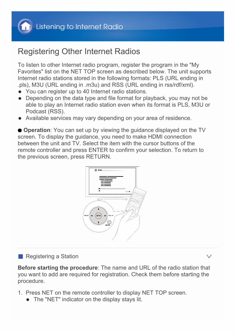
Operation: You can set up by viewing the guidance displayed on the TVscreen. To display the guidance, you need to make HDMI connectionbetween the unit and TV. Select the item with the cursor buttons of theremote controller and press ENTER to confirm your selection. To return tothe previous screen, press RETURN.
Registering a Station
Before starting the procedure: The name and URL of the radio station thatyou want to add are required for registration. Check them before starting theprocedure.
1. Press NET on the remote controller to display NET TOP screen. The "NET" indicator on the display stays lit.
Listening to Internet Radio

2. Select "My Favorites" with the cursors and press ENTER to display the"My Favorites" list screen.
3. Select a blank area of "My Favorites" with the cursors and press MENUto display the menu screen.
4. Select "Create new station" with the cursors and press ENTER to displaythe keyboard screen.
5. Enter the name and URL of the radio station to add. Select "Shift" and press ENTER to toggle between upper and lower
case. Select " " or " " and press ENTER to move the cursor to theselected direction. Select "Back Space" and press ENTER to deletethe character at the left of the cursor position.
Registering a Station with PC
Before starting the procedure: The name and URL of the radio station thatyou want to add are required for registration. Check them before starting theprocedure.
1. Press RECEIVER on the remote controller. Always press RECEIVER first to change the remote controller to
RECEIVER mode (the mode to operate this unit) since its mode maybe changed to operate another component.
2. Press HOME to display the HOME menu.
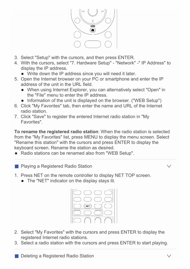
3. Select "Setup" with the cursors, and then press ENTER.4. With the cursors, select "7. Hardware Setup" - "Network" -" IP Address" to
display the IP address. Write down the IP address since you will need it later.
5. Open the Internet browser on your PC or smartphone and enter the IPaddress of the unit in the URL field. When using Internet Explorer, you can alternatively select "Open" in
the "File" menu to enter the IP address. Information of the unit is displayed on the browser. ("WEB Setup")
6. Click "My Favorites" tab, then enter the name and URL of the Internetradio station.
7. Click "Save" to register the entered Internet radio station in "MyFavorites".
To rename the registered radio station: When the radio station is selectedfrom the "My Favorites" list, press MENU to display the menu screen. Select"Rename this station" with the cursors and press ENTER to display thekeyboard screen. Rename the station as desired. Radio stations can be renamed also from "WEB Setup".
Playing a Registered Radio Station
1. Press NET on the remote controller to display NET TOP screen. The "NET" indicator on the display stays lit.
2. Select "My Favorites" with the cursors and press ENTER to display theregistered Internet radio stations.
3. Select a radio station with the cursors and press ENTER to start playing.
Deleting a Registered Radio Station
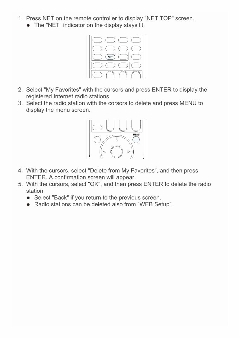
1. Press NET on the remote controller to display "NET TOP" screen. The "NET" indicator on the display stays lit.
2. Select "My Favorites" with the cursors and press ENTER to display theregistered Internet radio stations.
3. Select the radio station with the corsors to delete and press MENU todisplay the menu screen.
4. With the cursors, select "Delete from My Favorites", and then pressENTER. A confirmation screen will appear.
5. With the cursors, select "OK", and then press ENTER to delete the radiostation. Select "Back" if you return to the previous screen. Radio stations can be deleted also from "WEB Setup".
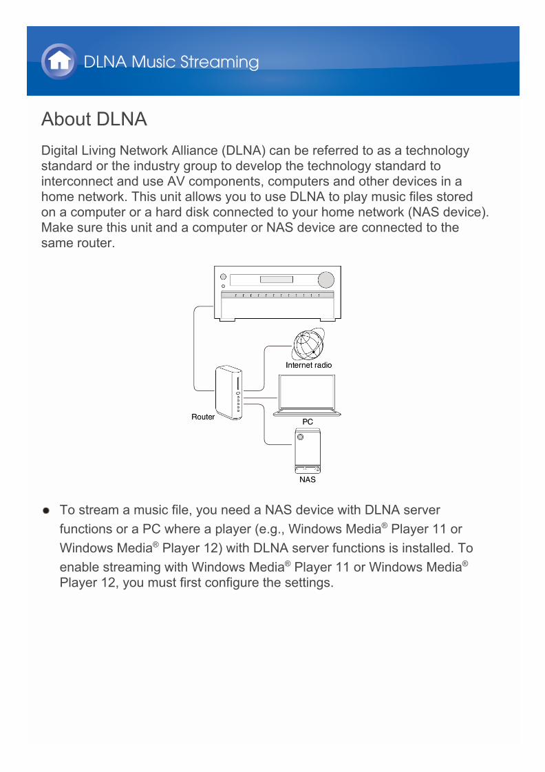
About DLNADigital Living Network Alliance (DLNA) can be referred to as a technologystandard or the industry group to develop the technology standard tointerconnect and use AV components, computers and other devices in ahome network. This unit allows you to use DLNA to play music files storedon a computer or a hard disk connected to your home network (NAS device).Make sure this unit and a computer or NAS device are connected to thesame router.
To stream a music file, you need a NAS device with DLNA serverfunctions or a PC where a player (e.g., Windows Media® Player 11 orWindows Media® Player 12) with DLNA server functions is installed. Toenable streaming with Windows Media® Player 11 or Windows Media®
Player 12, you must first configure the settings.
DLNA Music Streaming

Configuring the Windows Media® Player
Windows Media® Player 11
1. Turn on your PC and start Windows Media® Player 11.2. In the "Library" menu, select "Media Sharing" to display a dialog box.3. Select the "Share my media" check box, and then click "OK" to display
the compatible devices.4. Select this unit, and then click "Allow".
When it is clicked, the corresponding icon is checked.5. Click "OK" to close the dialog.
Windows Media® Player 12
1. Turn on your PC and start Windows Media® Player 12.2. In the "Stream" menu, select "Turn on media streaming" to display a
dialog box. If media streaming is already turned on, select "More streaming
options..." in the "Stream" menu to list players in the network, and thengo to step 4.
3. Click "Turn on media streaming" to list players in the network.4. Select this unit in "Media streaming options" and check that it is set to
"Allow".5. Click "OK" to close the dialog.
DLNA Music Streaming

DLNA PlaybackOperation: You can set up by viewing the guidance displayed on the TV
screen. To display the guidance, you need to make HDMI connectionbetween the unit and TV. Select the item with the cursor buttons of theremote controller and press ENTER to confirm your selection. To return tothe previous screen, press RETURN.
Playing Back
1. Start the server (Windows Media® Player 11, Windows Media® Player 12,or NAS device) containing the music files to play.
2. Press NET on the remote controller to display NET TOP screen. The "NET" indicator on the display stays lit. If the "NET" indicator
flashes, the unit is not properly connected to the network. When usinga wired LAN connection, check the Ethernet cable connection, andwhen using a wireless LAN connection, check whether the "Wi-Fi"indicator on the left side of the unit stays lit.
3. Select "DLNA" with the cursors and press ENTER.
DLNA Music Streaming

4. Select the target server with the cursors and press ENTER to display theitems list screen. Searching does not work in servers that do not support search
functions. The unit cannot access pictures and videos stored on servers. Contents stored on the server may not be displayed depending on the
server sharing settings.5. With the cursors, select the music file to play, and then press ENTER or
to start playback. If "No Item." is displayed, check whether the network is properly
connected.
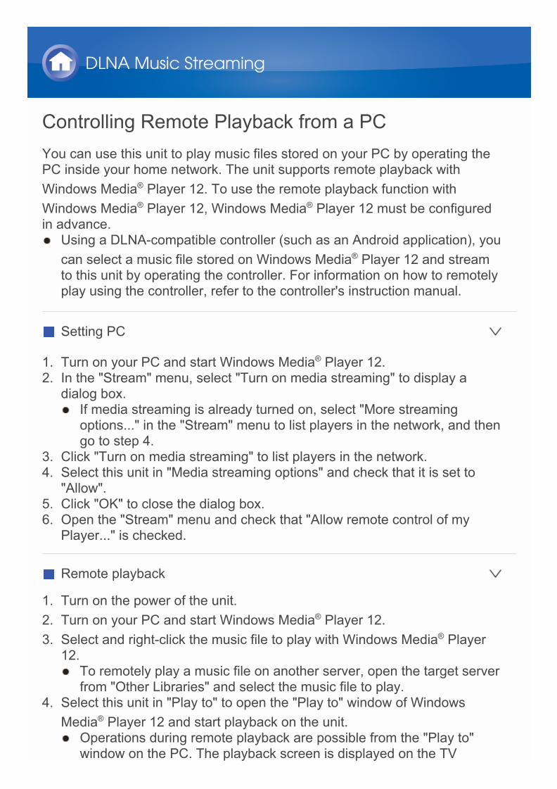
Controlling Remote Playback from a PCYou can use this unit to play music files stored on your PC by operating thePC inside your home network. The unit supports remote playback withWindows Media® Player 12. To use the remote playback function withWindows Media® Player 12, Windows Media® Player 12 must be configuredin advance. Using a DLNA-compatible controller (such as an Android application), you
can select a music file stored on Windows Media® Player 12 and streamto this unit by operating the controller. For information on how to remotelyplay using the controller, refer to the controller's instruction manual.
Setting PC
1. Turn on your PC and start Windows Media® Player 12.2. In the "Stream" menu, select "Turn on media streaming" to display a
dialog box. If media streaming is already turned on, select "More streaming
options..." in the "Stream" menu to list players in the network, and thengo to step 4.
3. Click "Turn on media streaming" to list players in the network.4. Select this unit in "Media streaming options" and check that it is set to
"Allow".5. Click "OK" to close the dialog box.6. Open the "Stream" menu and check that "Allow remote control of my
Player..." is checked.
Remote playback
1. Turn on the power of the unit.2. Turn on your PC and start Windows Media® Player 12.3. Select and right-click the music file to play with Windows Media® Player
12. To remotely play a music file on another server, open the target server
from "Other Libraries" and select the music file to play.4. Select this unit in "Play to" to open the "Play to" window of Windows
Media® Player 12 and start playback on the unit. Operations during remote playback are possible from the "Play to"
window on the PC. The playback screen is displayed on the TV
DLNA Music Streaming

connected to the HDMI output of the unit. If your PC is running onWindows® 8, click "Play to", and then select this unit.
5. Adjust the volume using the volume bar on the "Play to" window. Sometimes, the volume displayed on the remote playback window
may differ from that appeared on the display of the unit. When the volume is adjusted from the unit, the value is not reflected in
the "Play to" window. This unit cannot play music files remotely in the following conditions.
– It is using a network service.– It is playing a music file on a USB storage device.– "Agree" was not selected in the "DISCLAIMER" screen that was
displayed when the NET input was selected on the unit for the firsttime.

About Shared FolderA shared folder is configured in a network device such as a PC or NAS (harddisk connected to your home network) for access from other users.You can play music files in a shared folder on your PC or NAS connected tothe same home network as that of the unit. To play music files in a sharedfolder, you must first configure Windows® 8 or Windows® 7, Make sure theunit and PC or NAS device are connected to the same router.
The sharing options must be configured and a shared folder created onthe PC in advance.
For information on how to configure the NAS device and create a sharedfolder, refer to the NAS device's instruction manual.
Music Streaming from a Shared Folder
Setting PC
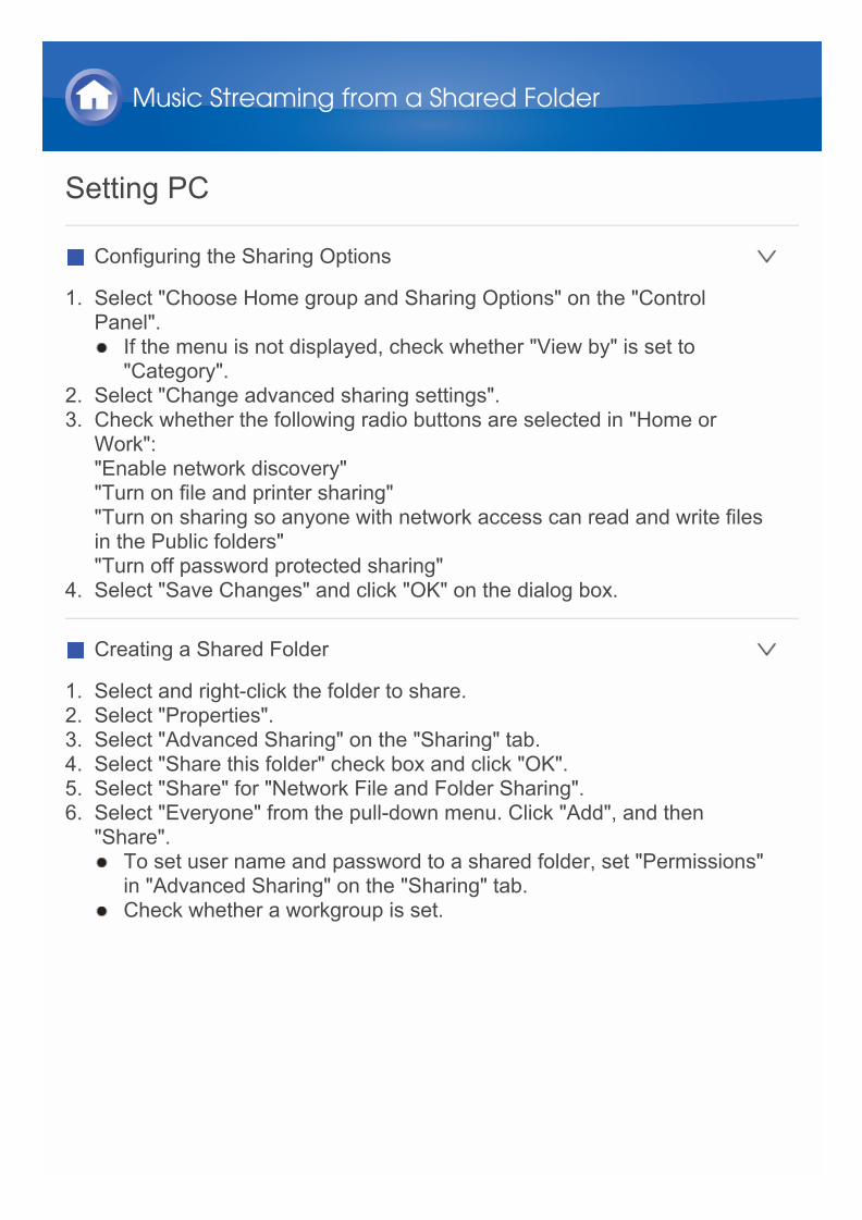
Configuring the Sharing Options
1. Select "Choose Home group and Sharing Options" on the "ControlPanel". If the menu is not displayed, check whether "View by" is set to
"Category".2. Select "Change advanced sharing settings".3. Check whether the following radio buttons are selected in "Home or
Work":"Enable network discovery""Turn on file and printer sharing""Turn on sharing so anyone with network access can read and write filesin the Public folders""Turn off password protected sharing"
4. Select "Save Changes" and click "OK" on the dialog box.
Creating a Shared Folder
1. Select and right-click the folder to share.2. Select "Properties".3. Select "Advanced Sharing" on the "Sharing" tab.4. Select "Share this folder" check box and click "OK".5. Select "Share" for "Network File and Folder Sharing".6. Select "Everyone" from the pull-down menu. Click "Add", and then
"Share". To set user name and password to a shared folder, set "Permissions"
in "Advanced Sharing" on the "Sharing" tab. Check whether a workgroup is set.
Music Streaming from a Shared Folder

Playing from a Shared FolderOperation: You can set up by viewing the guidance displayed on the TV
screen. To display the guidance, you need to make HDMI connectionbetween the unit and TV. Select the item with the cursor buttons of theremote controller and press ENTER to confirm your selection. To return tothe previous screen, press RETURN.
Playing Back
1. Press NET on the remote controller to display NET TOP screen on theTV. The "NET" indicator on the display stays lit. If the "NET" indicator
flashes, the unit is not properly connected to the network. When usinga wired LAN connection, check the Ethernet cable connection, andwhen using a wireless LAN connection, check whether the "Wi-Fi"indicator on the left side of the unit is lit.
2. Select "Home Media" with the cursors, and then press ENTER.3. Select the target server with the cursors, and then press ENTER.
Music Streaming from a Shared Folder
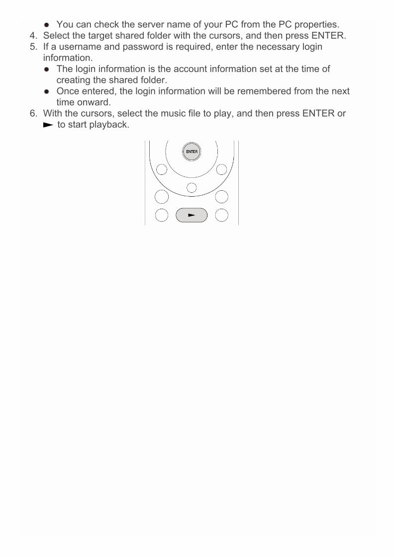
You can check the server name of your PC from the PC properties.4. Select the target shared folder with the cursors, and then press ENTER.5. If a username and password is required, enter the necessary login
information. The login information is the account information set at the time of
creating the shared folder. Once entered, the login information will be remembered from the next
time onward.6. With the cursors, select the music file to play, and then press ENTER or
to start playback.
About the Remote ControllerThe remote controller of this unit allows you to play music files stored onUSB storage devices, Internet radio, PCs and NAS devices on your homenetwork, as well as on Bluetooth-enabled devices. It also allows you to viewinformation of the music file being played and perform various otheroperations. Available buttons may vary depending on the service and device to play. Some buttons cannot be used with Bluetooth-enabled devices.
Furthermore, the Bluetooth-enabled devices must support the AVRCPprofile. Some devices may not be operated, even when they supportAVRCP profile.
Using Remote Controller for Playing Music Files
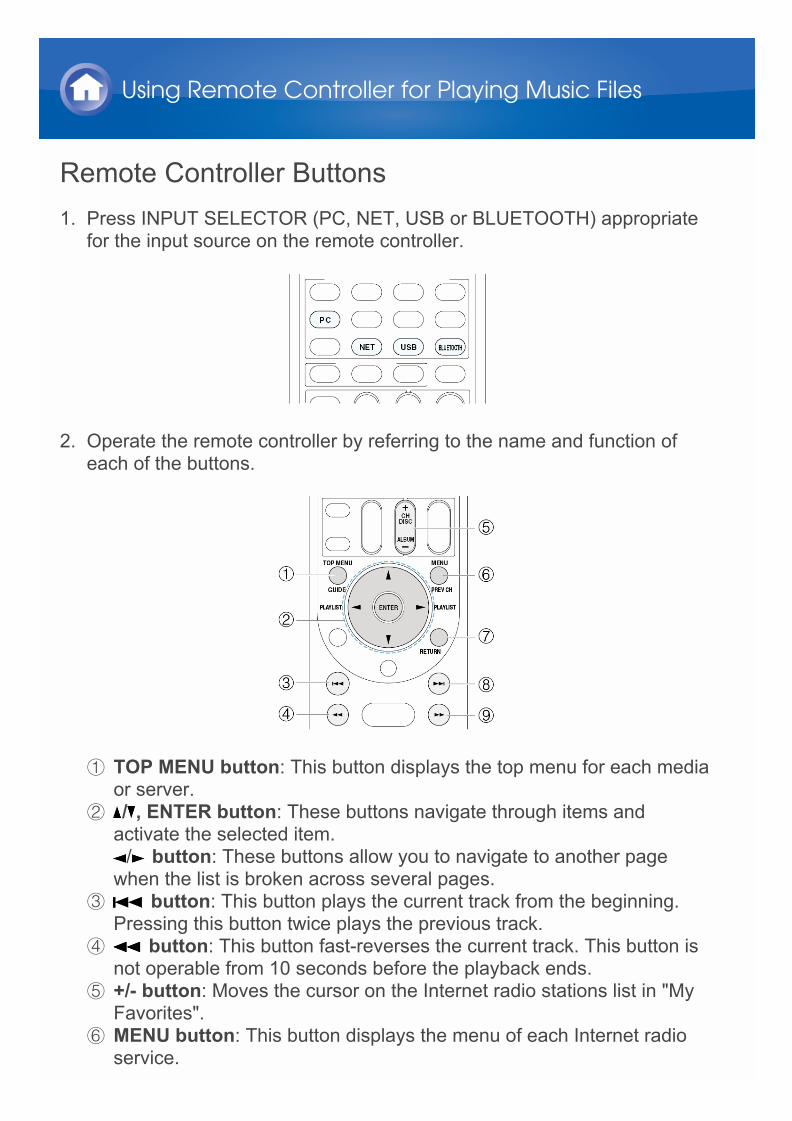
Remote Controller Buttons1. Press INPUT SELECTOR (PC, NET, USB or BLUETOOTH) appropriate
for the input source on the remote controller.
2. Operate the remote controller by referring to the name and function ofeach of the buttons.
1 TOP MENU button: This button displays the top menu for each mediaor server.
2 / , ENTER button: These buttons navigate through items andactivate the selected item.
/ button: These buttons allow you to navigate to another pagewhen the list is broken across several pages.
3 button: This button plays the current track from the beginning.Pressing this button twice plays the previous track.
4 button: This button fast-reverses the current track. This button isnot operable from 10 seconds before the playback ends.
5 +/- button: Moves the cursor on the Internet radio stations list in "MyFavorites".
6 MENU button: This button displays the menu of each Internet radioservice.
Using Remote Controller for Playing Music Files
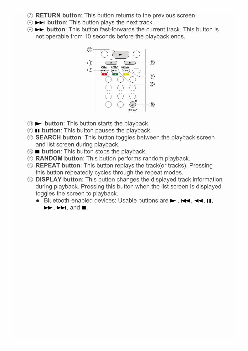
7 RETURN button: This button returns to the previous screen.8 button: This button plays the next track.9 button: This button fast-forwards the current track. This button is
not operable from 10 seconds before the playback ends.
F button: This button starts the playback.G button: This button pauses the playback.H SEARCH button: This button toggles between the playback screen
and list screen during playback.I button: This button stops the playback.J RANDOM button: This button performs random playback.K REPEAT button: This button replays the track(or tracks). Pressing
this button repeatedly cycles through the repeat modes.L DISPLAY button: This button changes the displayed track information
during playback. Pressing this button when the list screen is displayedtoggles the screen to playback. Bluetooth-enabled devices: Usable buttons are , , , ,
, , and .
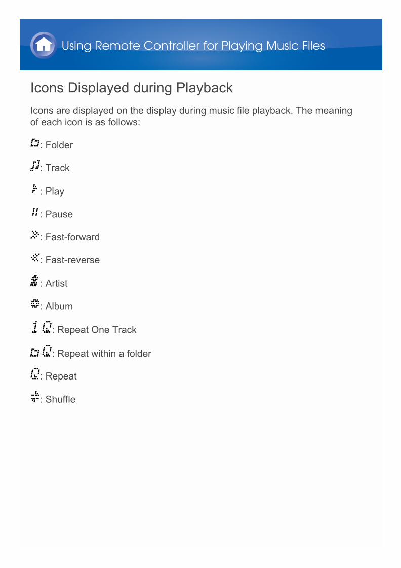
Icons Displayed during PlaybackIcons are displayed on the display during music file playback. The meaningof each icon is as follows:
: Folder
: Track
: Play
: Pause
: Fast-forward
: Fast-reverse
: Artist
: Album
: Repeat One Track
: Repeat within a folder
: Repeat
: Shuffle
Using Remote Controller for Playing Music Files
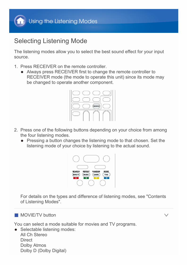
Selecting Listening ModeThe listening modes allow you to select the best sound effect for your inputsource.
1. Press RECEIVER on the remote controller. Always press RECEIVER first to change the remote controller to
RECEIVER mode (the mode to operate this unit) since its mode maybe changed to operate another component.
2. Press one of the following buttons depending on your choice from amongthe four listening modes. Pressing a button changes the listening mode to that chosen. Set the
listening mode of your choice by listening to the actual sound.
For details on the types and difference of listening modes, see "Contentsof Listening Modes".
MOVIE/TV button
You can select a mode suitable for movies and TV programs. Selectable listening modes:
All Ch StereoDirectDolby AtmosDolby D (Dolby Digital)
Using the Listening Modes
Dolby D+ (Dolby Digital Plus)Dolby SurroundDolby TrueHDDSDDTSDTS 96/24DTS ExpressDTS-HD HR (DTS-HD High Resolution Audio)DTS-HD MSTR (DTS-HD Master Audio)DTS Neo:X Cinema + THX CinemaES Discrete (DTS-ES Discrete)ES Matrix (DTS-ES Matrix)Full MonoMonoMultichannelNeo:X CinemaT-D (Theater-Dimensional)THX CinemaTHX S2 Cinema (THX Select2 Cinema)THX Surr EX (THX Surround EX)TV Logic
MUSIC button
You can select a mode suitable for music. Selectable listening modes:
All Ch StereoDirectDolby AtmosDolby D (Dolby Digital)Dolby D+ (Dolby Digital Plus)Dolby SurroundDolby TrueHDDSDDTSDTS 96/24DTS ExpressDTS-HD HR (DTS-HD High Resolution Audio)DTS-HD MSTR (DTS-HD Master Audio)DTS Neo:X Music + THX MusicES Discrete (DTS-ES Discrete)ES Matrix (DTS-ES Matrix)Full MonoMultichannelNeo:X MusicOrchestra

Pure AudioStereoStudio-MixTHX MusicTHX S2 Music (THX Select2 Music)Unplugged
GAME button
You can select a mode suitable for games. Selectable listening modes:
All Ch StereoDirectDolby AtmosDolby D (Dolby Digital)Dolby D+ (Dolby Digital Plus)Dolby SurroundDolby TrueHDDSDDTSDTS 96/24DTS ExpressDTS-HD HR (DTS-HD High Resolution Audio)DTS-HD MSTR (DTS-HD Master Audio)DTS Neo:X Game + THX GamesES Discrete (DTS-ES Discrete)ES Matrix (DTS-ES Matrix)Full MonoNeo:X GameGame-ActionGame-RockGame-RPGGame-SportsMultichannelT-D (Theater-Dimensional)THX GamesTHX S2 Games (THX Select2 Games)
THX button
You can select a THX listening mode. Selectable listening modes:
DTS Neo:X Cinema + THX CinemaDTS Neo:X Music + THX MusicDTS Neo:X Game + THX GamesTHX Cinema
THX MusicTHX GamesTHX S2 Cinema (THX Select2 Cinema)THX S2 Games (THX Select2 Games)THX S2 Music (THX Select2 Music)THX Surr EX (THX Surround EX)
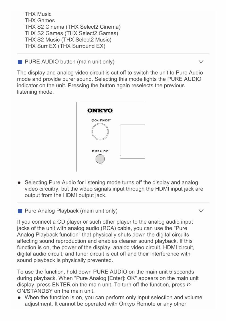
PURE AUDIO button (main unit only)
The display and analog video circuit is cut off to switch the unit to Pure Audiomode and provide purer sound. Selecting this mode lights the PURE AUDIOindicator on the unit. Pressing the button again reselects the previouslistening mode.
Selecting Pure Audio for listening mode turns off the display and analogvideo circuitry, but the video signals input through the HDMI input jack areoutput from the HDMI output jack.
Pure Analog Playback (main unit only)
If you connect a CD player or such other player to the analog audio inputjacks of the unit with analog audio (RCA) cable, you can use the "PureAnalog Playback function" that physically shuts down the digital circuitsaffecting sound reproduction and enables cleaner sound playback. If thisfunction is on, the power of the display, analog video circuit, HDMI circuit,digital audio circuit, and tuner circuit is cut off and their interference withsound playback is physically prevented.
To use the function, hold down PURE AUDIO on the main unit 5 secondsduring playback. When "Pure Analog [Enter]: OK" appears on the main unitdisplay, press ENTER on the main unit. To turn off the function, press ON/STANDBY on the main unit. When the function is on, you can perform only input selection and volume
adjustment. It cannot be operated with Onkyo Remote or any other

application that can control the unit. It cannot be used when "TUNER", "NET", "USB", or "BLUETOOTH" input
is selected or the multi-zone function is on. The Auto Standby setting becomes off if the function is on.
Contents of Listening ModesSelectable listening modes will differ depending on the number of inputsource channels and the actual speaker configuration. Listening modesavailable when headphones are connected are: Pure Audio, Mono, Direct,and Stereo.
Lists in alphabetic order (A-Z)
All Ch Stereo
Ideal for background music, this mode fills the entire listening area withstereo sound from the front, surround, and surround back speakers. Input source: MONO, STEREO, 5.1 ch, 7.1 ch
Direct
In this mode, audio from the input source is output as-is. For example, if a2 ch source from a music CD is input, the output will be stereo, or if DolbyDigital signal is input, the sound field will be controlled in accordance withthe number of channels present. Input source: MONO, STEREO, 5.1 ch, 7.1 ch
Dolby Atmos
Introduced first in the cinema, Dolby Atmos brings a revolutionary sense ofdimension and immersion to the Home Theater experience. Dolby Atmos isan adaptable and scalable object based format that reproduces audio asindependent sounds (or objects) that can be accurately positioned and movedynamically throughout the 3 dimensional listening space during playback. Akey ingredient of Dolby Atmos is the introduction of a height plane of soundabove the listener. Surround back speakers, height speakers or wide speakers need to be
installed. This listening mode can be selected only if the input signal is Dolby
Atmos.
Dolby D
This mode is for use with Dolby Digital sources. The audio from the input
Using the Listening Modes
source is output as-is, without surround sound processing. Input source: 5.1 ch This listening mode can be selected only if your Blu-ray Disc/DVD player
is digitally connected to the unit or the player's output setting is bitstream.
Dolby D+
This mode is for use with Dolby Digital Plus sources. The audio from theinput source is output as-is, without surround sound processing. Input source: 5.1 ch, 7.1 ch This listening mode can be selected only if your Blu-ray Disc/DVD player
is digitally connected to the unit or the player's output setting is bitstream. When playing back 3.1 ch or 5.1 ch sources from Blu-ray Discs, Dolby
Digital is automatically applied.
Dolby Surround
Dolby surround is a next generation surround technology that intelligently upmixes stereo; 5.1 and 7.1 content for playback through your surroundspeaker system. Dolby surround is compatible with traditional speakerlayouts, as well as Dolby Atmos enabled playback systems that employ in-ceiling speakers or products with Dolby speaker technology. Input source: STEREO, 5.1 ch, 7.1 ch
Dolby TrueHD
This mode is for use with Dolby TrueHD sources. The audio from the inputsource is output as-is, without surround sound processing. Input source: 5.1 ch, 7.1 ch This listening mode can be selected only if your Blu-ray Disc/DVD player
is digitally connected to the unit or the player's output setting is bitstream.
DSD
This mode is for use with DSD sources. The audio from the input source isoutput as-is, without surround sound processing. Input source: 5.1 ch This unit supports DSD signals input through HDMI IN. However,
depending on the connected player, better sound is possible when outputfrom the PCM output of the player. In that case, configure the player forPCM output.
This listening mode can be selected only if your Blu-ray Disc/DVDplayer's output setting is DSD.
DTS
This mode is for use with DTS sources. The audio from the input source isoutput as-is, without surround sound processing. Input source: 5.1 ch This listening mode can be selected only if your Blu-ray Disc/DVD player
is digitally connected to the unit or the player's output setting is bitstream.
DTS 96/24
This mode is for use with DTS 96/24 sources. The audio from the inputsource is output as-is, without surround sound processing. With 96 kHzsampling rate and 24-bit resolution, it provides superior fidelity. Input source: 5.1 ch Depending on the settings, this listening mode becomes DTS. This listening mode can be selected only if your Blu-ray Disc/DVD player
is digitally connected to the unit or the player's output setting is bitstream.
DTS Express
This mode is for use with DTS Express sources. The audio from the inputsource is output as-is, without surround sound processing. Input source: 5.1 ch This listening mode can be selected only if your Blu-ray Disc/DVD player
is digitally connected to the unit or the player's output setting is bitstream.
DTS-HD HR
This mode is for use with DTS-HD High Resolution Audio sources. Theaudio from the input source is output as-is, without surround soundprocessing. Input source: 5.1 ch, 7.1 ch This listening mode can be selected only if your Blu-ray Disc/DVD player
is digitally connected to the unit or the player's output setting is bitstream.
DTS-HD MSTR
This mode is for use with DTS-HD Master Audio sources. The audio from theinput source is output as-is, without surround sound processing. Input source: 5.1 ch, 7.1 ch This listening mode can be selected only if your Blu-ray Disc/DVD player
is digitally connected to the unit or the player's output setting is bitstream.
DTS Neo:X
This mode expands various input sources for up to 11 channel playback. Inthis mode, you can enjoy natural and realistic broad surround sound by
adding front high/ front wide speakers that create dome-shaped sound field. DTS Neo:X listening mode cannot be selected for 192 kHz or Dolby
TrueHD input signals.
– Neo:X Cinema: Use this mode with any 2 ch movie. Input source: STEREO, 5.1 ch, 7.1 ch
– Neo:X Music: Use this mode with any 2 ch music source. Input source: STEREO, 5.1 ch, 7.1 ch
– Neo:X Game: Use this mode with any 2 ch video game source. Input source: STEREO, 5.1 ch, 7.1 ch
ES Discrete
This mode is for use with DTS-ES Discrete sources and enables 6.1 ch or7.1 ch playback using surround back channel. Completely discrete sevenchannels will improve spatial imaging and enable 360-degree soundlocalization producing a sound crossing between the surround channels. Input source: 6.1 ch, 7.1 ch Surround back speakers need to be installed. This listening mode can be selected only if your Blu-ray Disc/DVD player
is digitally connected to the unit or the player's output setting is bitstream. Use on the DVD with DTS ES logo, particularly on the software
containing DTS-ES Matrix soundtrack. Playback becomes DTS if no surround back speaker is connected.
ES Matrix
This mode is for use with DTS-ES Matrix soundtrack and enables 6.1 ch or7.1 ch playback using matrix-encoded back channel. Input source: 6.1 ch, 7.1 ch Surround back speakers need to be installed. This listening mode can be selected only if your Blu-ray Disc/DVD player
is digitally connected to the unit or the player's output setting is bitstream. Use on the CD, DVD or LD with DTS ES logo, particularly on the software
containing DTS-ES Matrix soundtrack. Playback becomes DTS if no surround back speaker is connected.
Full Mono
In this mode, all speakers output the same sound in mono, so the sound youhear is the same regardless of where you are within the listening room. Input source: MONO, STEREO, 5.1 ch, 7.1 ch
Game-Action
In this mode, sound localization is distinct with emphasis on bass. Input source: MONO, STEREO, 5.1 ch, 7.1 ch Surround speakers need to be installed.
Game-Rock
In this mode, sound pressure is emphasized to heighten live feel. Input source: MONO, STEREO, 5.1 ch, 7.1 ch Surround speakers need to be installed.
Game-RPG
In this mode, the sound has a dramatic feel with a similar atmosphere toOrchestra mode. Input source: MONO, STEREO, 5.1 ch, 7.1 ch Surround speakers need to be installed.
Game-Sports
Suitable for audio source with much reverberation. Input source: MONO, STEREO, 5.1 ch, 7.1 ch Surround speakers need to be installed.
Mono
Use this mode when watching an old movie with a mono soundtrack, or useit to separately reproduce soundtracks in two different languages recorded inthe left and right channels of some movies. It is also suitable for DVDs orother sources containing multiplexed audio. Input source: MONO, STEREO, 5.1 ch, 7.1 ch
Multichannel
This mode is for use with PCM multichannel sources. The audio from theinput source is output as-is, without surround sound processing. Input source: 5.1 ch, 7.1 ch
Orchestra
Suitable for classical or operatic music, This mode emphasizes the surroundchannels in order to widen the stereo image, and simulates the naturalreverberation of a large hall. Input source: MONO, STEREO, 5.1 ch, 7.1 ch Surround speakers need to be installed.
Pure Audio
This mode reproduces the original sound accurately. Since the audio fromthe input source is output without surround sound processing and the displayand video circuitry are turned off, possible noise sources are minimized for arealistic audio reproduction. Input source: MONO, STEREO, 5.1 ch, 7.1 ch This mode cannot be selected when Zone 2/Zone 3 is active. Activating
Zone 2/Zone 3 when this mode is selected, automatically switches thelistening mode to Direct.
Stereo
In this mode, sound is output from the front left and rightspeakers/subwoofer. Input source: MONO, STEREO, 5.1 ch, 7.1 ch
Studio-Mix
Suitable for rock or pop music, Listening to music in this mode creates alively sound field with a powerful acoustic image, like being at a club or rockconcert. Input source: MONO, STEREO, 5.1 ch, 7.1 ch Surround speakers need to be installed.
T-D
In this mode, you can enjoy a virtual playback of multichannel surroundsound even with only two or three speakers. This works by controlling howsounds reach the listener’s left and right ears. Input source: MONO, STEREO, 5.1 ch, 7.1 ch Good results may not be possible if there is too much reverb, so we
recommend that you use this mode in an environment with little or nonatural reverb.
THX
Founded by George Lucas, THX develops stringent standards that ensuremovies are reproduced in movie theaters and home theaters just as thedirector intended. THX Modes carefully optimize the tonal andspatial characteristics of the soundtrack for reproduction in the home-theaterenvironment. They can be used with 2-channel matrixed and multichannelsources. Surround back speaker output depends on the source material andthe selected listening mode. The THX mode can finely adjust the acoustic and spatial characteristics
of the soundtrack for the best reproduction of home theater sound. It willwork on 2 ch source and multichannel source. Surround back sound willdiffer depending on the source and selected listening mode.
– DTS Neo:X Cinema + THX Cinema: The combination mode of DTSNeo:X Cinema and THX Cinema mode can be used. "Neo:X" and "THX"light on the unit’s display. Input source: STEREO, 5.1 ch, 7.1 ch Surround back speaker need to be installed when playing with
speaker configuration of more than 7.2 ch.
– DTS Neo:X Music + THX Music: The combination mode of DTS Neo:XMusic and THX Music mode can be used. "Neo:X" and "THX" light on theunit’s display. Input source: STEREO, 5.1 ch, 7.1 ch Surround back speaker need to be installed when playing with
speaker configuration of more than 7.2 ch.
– DTS Neo:X Game + THX Games: The combination mode of DTS Neo:XGame and THX Games mode can be used. "Neo:X" and "THX" light onthe unit’s display. Input source: STEREO, 5.1 ch, 7.1 ch Surround back speaker need to be installed when playing with
speaker configuration of more than 7.2 ch.
– THX Cinema: THX Cinema mode corrects theatrical soundtracks forplayback in a home theater environment. In this mode, THX LoudnessPlus is configured for cinema levels and Re-EQ, Timbre Matching, andAdaptive Decorrelation are active. Input source: 5.1 ch, 7.1 ch Surround speakers need to be installed.
– THX Games: THX Games mode is meant for spatially accurate playbackof game audio, which is often mixed similarly to movies but in a smallerenvironment. THX Loudness Plus is configured for game audio levels,with Timbre Matching active. Input source: 5.1 ch, 7.1 ch Surround speakers need to be installed.
– THX Music: THX Music mode is tailored for listening to music, which istypically mastered at significantly higher levels than movies. In this mode,THX Loudness Plus is configured for music playback and only TimbreMatching is active. Input source: 5.1 ch, 7.1 ch Surround speakers need to be installed.
– THX S2 Cinema: The THX Select2 Cinema mode provides high-qualitysurround sound experience by expanding 5.1 ch movie source for 7.1 ch
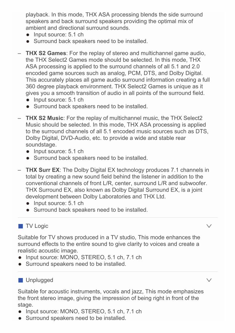
playback. In this mode, THX ASA processing blends the side surroundspeakers and back surround speakers providing the optimal mix ofambient and directional surround sounds. Input source: 5.1 ch Surround back speakers need to be installed.
– THX S2 Games: For the replay of stereo and multichannel game audio,the THX Select2 Games mode should be selected. In this mode, THXASA processing is applied to the surround channels of all 5.1 and 2.0encoded game sources such as analog, PCM, DTS, and Dolby Digital.This accurately places all game audio surround information creating a full360 degree playback environment. THX Select2 Games is unique as itgives you a smooth transition of audio in all points of the surround field. Input source: 5.1 ch Surround back speakers need to be installed.
– THX S2 Music: For the replay of multichannel music, the THX Select2Music should be selected. In this mode, THX ASA processing is appliedto the surround channels of all 5.1 encoded music sources such as DTS,Dolby Digital, DVD-Audio, etc. to provide a wide and stable rearsoundstage. Input source: 5.1 ch Surround back speakers need to be installed.
– THX Surr EX: The Dolby Digital EX technology produces 7.1 channels intotal by creating a new sound field behind the listener in addition to theconventional channels of front L/R, center, surround L/R and subwoofer.THX Surround EX, also known as Dolby Digital Surround EX, is a jointdevelopment between Dolby Laboratories and THX Ltd. Input source: 5.1 ch Surround back speakers need to be installed.
TV Logic
Suitable for TV shows produced in a TV studio, This mode enhances thesurround effects to the entire sound to give clarity to voices and create arealistic acoustic image. Input source: MONO, STEREO, 5.1 ch, 7.1 ch Surround speakers need to be installed.
Unplugged
Suitable for acoustic instruments, vocals and jazz, This mode emphasizesthe front stereo image, giving the impression of being right in front of thestage. Input source: MONO, STEREO, 5.1 ch, 7.1 ch Surround speakers need to be installed.
Reference
Dialogue NormalizationDialogue Normalization (DialogNorm) is a feature of Dolby Digital, whichis used to keep the programs at the same average listening level so theuser does not have to change the volume control between Dolby Digital,Dolby Digital Plus and Dolby TrueHD programs. When playing backsoftware which has been encoded in Dolby Digital, Dolby Digital Plus andDolby TrueHD, sometimes you may see a brief message in the frontpanel display which will read "DialogNorm: X dB" (X being a numericvalue). The display is showing how the program level relates with THXcalibration level. If you want to play the program at calibrated theatricallevels, you may wish to adjust the volume. For example, if you see thefollowing message: "DialogNorm: +4dB" in the front panel display, to keepthe overall output level at THX calibrated loudness, just turn down thevolume control by 4dB. However, unlike a movie theater where theplayback loudness is preset, you can choose your preferred volumesetting for best enjoyment.
THX Cinema ProcessingTHX is an exclusive set of standards and technologies established by theworld-renowned film production company Lucasfilm Ltd. THX grew fromGeorge Lucas’ personal desire to make your experience of the filmsoundtrack in both movie theaters and in your home theater as faithful aspossible to what the director intended. Movie soundtracks are mixed inspecial environments called dubbing stages and are designed to beplayed back in movie theaters with similar equipment and conditions.Most of those soundtracks are remixed using flat response loudspeakerssimilar to those used in the small home theater environment before beingtransferred onto Blu-ray Discs, DVD, etc. THX engineers developedpatented technologies to accurately translate the sound from the movietheater environment into the home, correcting the tonal and spatial errorsthat occur. On this product, when the THX indicator is on, THX featuresare automatically added in Cinema modes (e.g. THX Cinema, THXSurround EX).
Timbre MatchingThe human ear changes our perception of a sound depending on thedirection from which the sound is coming. In a movie theater, there is anarray of surround speakers so that the surround information is all aroundyou. In a home theater, you may only have two speakers located to theside of your head. In this case, the Timbre Matching feature filters theinformation going to the surround speakers so that they more closelymatch the tonal characteristics of the sound coming from the frontspeakers. This ensures seamless panning between the front and
surround speakers.
Adaptive DecorrelationIn a movie theater, a large number of surround speakers help create anenveloping surround sound experience. If a home theater only has twosidewall surround speakers, the surround speakers may sound similar toheadphones lacking spaciousness and envelopment. Surround soundswill also collapse toward the closet speaker as you move away from themiddle seating position. Adaptive Decorrelation slightly changes onesurround channel’s time and phase relationship with respect to the othersurround experience as in a movie theater using only two speakers.
ASA (Advanced Speaker Array)ASA is a proprietary THX technology which processes the audio on thetwo side and two back surround speakers for the optional surround soundexperience. When you set up your home theater system using eightspeaker outputs (Front Left, Center, Front Right, Surround Right,Surround Back Right, Surround Back Left, Surround Left, andSubwoofer), be sure to go to the THX Audio Setup screen and choosethe setting that closely corresponds to the back speaker spacing. This willreoptimize the surround sound field. ASA is used in three modes: THXSelect2 Cinema, THX Select2 Music and THX Select2 Games.

Checking the Input FormatYou can check the audio format of the input signals. While audio from theplayer is being input, press DISPLAY on the remote controller several timesto switch the information shown on the main unit display. If "Dolby D 5.1" isdisplayed in Signal format, the Dolby Digital 5.1 ch signals are being input. The number of channels is not displayed when the input signal format is
"Dolby Atmos".
Using the Listening Modes

How to SetThe unit allows you to configure advanced settings, such as to remap theinput and input selector, or configure various speaker settings in order toprovide even better experience. Make the settings in "Setup" of the HOMEmenu.
Operation: You can set up by viewing the guidance displayed on the TVscreen. To display the guidance, you need to make HDMI connectionbetween the unit and TV. Select the item with the cursor buttons of theremote controller and press ENTER to confirm your selection. To return tothe previous screen, press RETURN. To return to the HOME menu, pressHOME.
Operation
1. Press RECEIVER on the remote controller. Always press RECEIVER first to change the remote controller to
RECEIVER mode (the mode to operate this unit) since its mode maybe changed to operate another component.
Advanced Settings
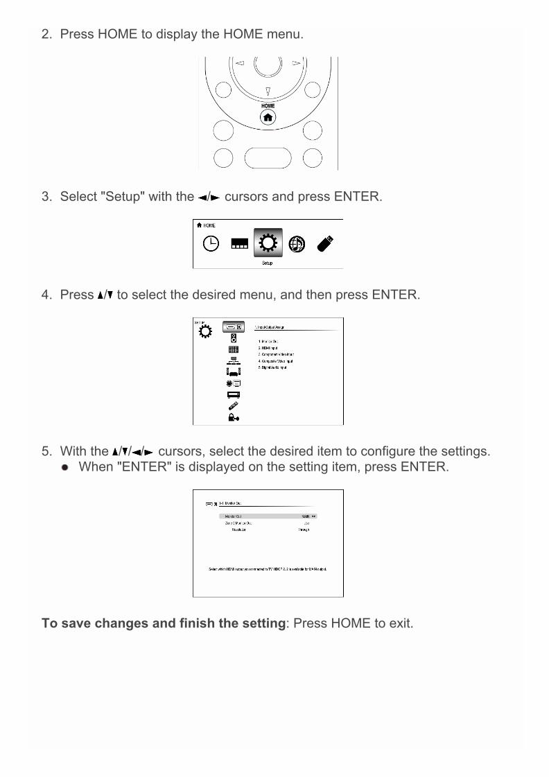
2. Press HOME to display the HOME menu.
3. Select "Setup" with the / cursors and press ENTER.
4. Press / to select the desired menu, and then press ENTER.
5. With the / / / cursors, select the desired item to configure the settings. When "ENTER" is displayed on the setting item, press ENTER.
To save changes and finish the setting: Press HOME to exit.

1.Input/Output Assign
Monitor Out
The video input signals input to the unit will be converted when they areoutput from the HDMI OUT jack to the TV so that their resolution can matchthat of the TV used.
Monitor Out
Default Value: MAIN
Select the HDMI jack to be connected with TV."MAIN": When connecting the TV to the HDMI OUT MAIN jack"SUB": When connecting the TV to the HDMI OUT SUB jack"MAIN+SUB": When connecting to both the MAIN and SUB jacks Video signals input to the COMPOSIT VIDEO input jack or the
COMPONENT VIDEO input jacks will be upconverted to HDMIsignals and then output from the HDMI OUT jack.
Different "Resolution" values can be set for “MAIN” and “SUB”. The HDMI jack of this unit is compliant with HDCP2.2 (HDMI OUT
MAIN and HDMI IN3 jacks only).
Zone 2 Monitor Out
Default Value: Use
This is the setting to output to TV of Zone 2 which is connected to theHDMI OUT ZONE2 jack."Use": Enable this function"Not Use": Disable this function
Resolution
Default Value: Through
Specify the output resolution of the HDMI OUT jacks. The imageresolution of the unit will be converted so that it can match theresolution supported by the TV used."Through": The output resolution will be the same as that of the inputsignals."Auto": The resolution will automatically be converted according to
Advanced Settings
the resolution supported by the TV."480p (480p/576p)", "720p", "1680×720p", "1080i", "1080p","2560×1080p": Select the desired resolution."4K": About four times as high resolution as 1080p (3840×2160 or4096×2160 pixels depending on the resolution supported by theconnected TV)"Source": The output resolution will be the one set for "Resolution"which is shown in the section "4. Source Setup" - "Picture Adjust" -"Resolution". If "1080p" is selected, 1080p/24 input signals will be output with
an unchanged resolution. If the selected resolution is not supported by the monitor, the
video is output in the same resolution as the input signal. If "4K" is selected, video signals may not be output to some types
of TV. For details, see "Supported Video Resolution of HDMI OUTMAIN/SUB Jacks" in "Troubleshooting".
If "Monitor Out" is set to "MAIN+SUB", only "Through" or "Auto"can be set.
You can check the video on the TV while making this setting.Select the value with the cursors and press ENTER. PressRETURN if no video is displayed. (except when "NET", "USB" or"BLUETOOTH" is selected)
HDMI Input
It is possible to change assignment of input selector buttons and the HDMIIN jacks.
BD/DVD
Default Value: HDMI 1
"HDMI 1" to "HDMI 7": Desired HDMI IN jack can be assigned toBD/DVD button. If you do not assign a jack, select "-----". To select anHDMI IN jack already assigned to another input selector, change itssetting to "-----" first.
CBL/SAT
Default Value: HDMI 2
"HDMI 1" to "HDMI 7": Desired HDMI IN jack can be assigned toCBL/SAT button. If you do not assign a jack, select "-----". To select anHDMI IN jack already assigned to another input selector, change itssetting to "-----" first.
STB/DVR

Default Value: HDMI 3 (HDCP 2.2)
"HDMI 1" to "HDMI 7": Desired HDMI IN jack can be assigned toSTB/DVR button. If you do not assign a jack, select "-----". To select anHDMI IN jack already assigned to another input selector, change itssetting to "-----" first.
GAME
Default Value: HDMI 4
"HDMI 1" to "HDMI 7": Desired HDMI IN jack can be assigned to GAMEbutton. If you do not assign a jack, select "-----". To select an HDMI INjack already assigned to another input selector, change its setting to "-----" first.
PC
Default Value: HDMI 5
"HDMI 1" to "HDMI 7": Desired HDMI IN jack can be assigned to PCbutton. If you do not assign a jack, select "-----". To select an HDMI INjack already assigned to another input selector, change its setting to "-----" first.
AUX
Default Value: Front/MHL
The setting cannot be changed.
TV/CD
Default Value: -----
"HDMI 1" to "HDMI 7": Desired HDMI IN jack can be assigned to TV/CDbutton. If you do not assign a jack, select "-----". To select an HDMI INjack already assigned to another input selector, change its setting to "-----" first.
PHONO
Default Value: -----
"HDMI 1" to "HDMI 7": Desired HDMI IN jack can be assigned toPHONO button. If you do not assign a jack, select "-----". To select anHDMI IN jack already assigned to another input selector, change itssetting to "-----" first.

Component Video Input
BD/DVD button and CBL/SAT button is assigned to COMPONENT VIDEOIN jack as factory default setting. This assignment can be changed ifnecessary. If you do not assign a jack, select "-----".
BD/DVD
Default Value: COMPONENT 1
"COMPONENT 1", "COMPONENT 2": COMPONENT VIDEO IN jack isassigned to BD/DVD button.
CBL/SAT
Default Value: COMPONENT 2
"COMPONENT 1", "COMPONENT 2": COMPONENT VIDEO IN jack isassigned to CBL/SAT button.
STB/DVR
Default Value: -----
"COMPONENT 1", "COMPONENT 2": COMPONENT VIDEO IN jack isassigned to STB/DVR button.
GAME
Default Value: -----
"COMPONENT 1", "COMPONENT 2": COMPONENT VIDEO IN jack isassigned to GAME button.
PC
Default Value: -----
"COMPONENT 1", "COMPONENT 2": COMPONENT VIDEO IN jack isassigned to PC button.
AUX
Default Value: -----
"COMPONENT 1", "COMPONENT 2": COMPONENT VIDEO IN jack isassigned to AUX button.
TV/CD
Default Value: -----
"COMPONENT 1", "COMPONENT 2": COMPONENT VIDEO IN jack isassigned to TV/CD button.
PHONO
Default Value: -----
"COMPONENT 1", "COMPONENT 2": COMPONENT VIDEO IN jack isassigned to PHONO button.
When "Monitor Out" is set to "MAIN" or "MAIN+SUB" and "Resolution" isset to "Through", the 480i/576i component signals will be output with theirresolution unchanged. So, TV sets not supporting these resolutions willnot be able to display video.
Composite Video Input
It is possible to change assignment of input selector buttons and theCOMPOSITE VIDEO IN V1 to 3 jacks.
BD/DVD
Default Value: -----
"VIDEO 1" to "VIDEO 3": Desired COMPOSITE VIDEO IN V jack canbe assigned to BD/DVD button. If you do not assign a jack, select "-----".
CBL/SAT
Default Value: VIDEO 1
"VIDEO 1" to "VIDEO 3": Desired COMPOSITE VIDEO IN V jack canbe assigned to CBL/SAT button. If you do not assign a jack, select "-----".
STB/DVR
Default Value: VIDEO 2
"VIDEO 1" to "VIDEO 3": Desired COMPOSITE VIDEO IN V jack canbe assigned to STB/DVR button. If you do not assign a jack, select "-----".

GAME
Default Value: VIDEO 3
"VIDEO 1" to "VIDEO 3": Desired COMPOSITE VIDEO IN V jack canbe assigned to GAME button. If you do not assign a jack, select "-----".
PC
Default Value: PC IN
The setting cannot be changed.
AUX
Default Value: FRONT
The setting cannot be changed.
TV/CD
Default Value: -----
"VIDEO 1" to "VIDEO 3": Desired COMPOSITE VIDEO IN V jack canbe assigned to TV/CD button. If you do not assign a jack, select "-----".
PHONO
Default Value: -----
"VIDEO 1" to "VIDEO 3": Desired COMPOSITE VIDEO IN V jack canbe assigned to PHONO button. If you do not assign a jack, select "-----".
When "Monitor Out" is set to "MAIN" or "MAIN+SUB" and "Resolution" isset to "Through", the 480i/576i composite signals will be output with theirresolution unchanged. So, TV sets not supporting these resolutions willnot be able to display video.
Digital Audio Input
It is possible to change assignment of input selector buttons and theDIGITAL IN COAXIAL 1 to 3/OPTICAL 1 to 2 jacks.
BD/DVD
Default Value: COAXIAL 1
"COAXIAL 1", "COAXIAL 2", "COAXIAL 3", "OPTICAL 1", "OPTICAL 2":
Desired DIGITAL IN jack can be assigned to BD/DVD button. If you donot assign a jack, select "-----".
CBL/SAT
Default Value: COAXIAL 2
"COAXIAL 1", "COAXIAL 2", "COAXIAL 3", "OPTICAL 1", "OPTICAL 2":Desired DIGITAL IN jack can be assigned to CBL/SAT button. If you donot assign a jack, select "-----".
STB/DVR
Default Value: COAXIAL 3
"COAXIAL 1", "COAXIAL 2", "COAXIAL 3", "OPTICAL 1", "OPTICAL 2":Desired DIGITAL IN jack can be assigned to STB/DVR button. If you donot assign a jack, select "-----".
GAME
Default Value: OPTICAL 1
"COAXIAL 1", "COAXIAL 2", "COAXIAL 3", "OPTICAL 1", "OPTICAL 2":Desired DIGITAL IN jack can be assigned to GAME button. If you donot assign a jack, select "-----".
PC
Default Value: -----
"COAXIAL 1", "COAXIAL 2", "COAXIAL 3", "OPTICAL 1", "OPTICAL 2":Desired DIGITAL IN jack can be assigned to PC button. If you do notassign a jack, select "-----".
AUX
Default Value: FRONT
The setting cannot be changed.
TV/CD
Default Value: OPTICAL 2
"COAXIAL 1", "COAXIAL 2", "COAXIAL 3", "OPTICAL 1", "OPTICAL 2":Desired DIGITAL IN jack can be assigned to TV/CD button. If you donot assign a jack, select "-----".

PHONO
Default Value: -----
"COAXIAL 1", "COAXIAL 2", "COAXIAL 3", "OPTICAL 1", "OPTICAL 2":Desired DIGITAL IN jack can be assigned to PHONO button. If you donot assign a jack, select "-----".
Supported sampling rates for PCM signals (stereo/mono) from a digitalinput are 32 kHz/44.1 kHz/48 kHz/88.2 kHz/96 kHz/16 bit, 20 bit, 24 bit.
2.Speaker SetupAllows you to change the speaker configuration such as presence or not ofsubwoofer, crossover frequency, and so on. Settings are automaticallyconfigured if you use the Automatic Speaker Setup.Furthermore, this setting cannot be selected if headphones are connected oraudio is output from the speakers of the TV.
Speaker Settings
Change the impedance of the connected speakers, the type of front speakerconnection and height speaker type.
Speaker Impedance
Default Value: 6ohms
Set the impedance (Ω) of the connected speakers."4ohms": When any of the connected speakers have 4 Ω or more toless than 6 Ω impedance"6ohms": When the connected speakers all have 6 Ω or moreimpedance
Front Speakers Type
Default Value: Normal
Select the type of front speaker connection."Normal": When front speakers are connected in a normal manner"Bi-Amp": When front speakers are bi-amp connected
Height 1 Speakers Type
Default Value: Not Use
Set the type of speakers connected to HEIGHT 1 speaker terminals.Select from the following options according to the type and layout of theconnected speakers: "Not Use", "Front High", "Top Front", "TopMiddle", "Dolby Enabled Speaker (Front)", "Dolby Enabled Speaker(Surround)", or "Dolby Enabled Speaker (Back)". If "Front Speakers Type" is set to "Bi-Amp", this setting will be set to
" Not Use".
Advanced Settings
"Dolby Enabled Speaker (Surround)" cannot be set when "Surround"is set to "None".
"Dolby Enabled Speaker (Back)" cannot be set when "Back" is set to"None" or "Back ch" is set to "1ch".
Height 2 Speakers Type
Default Value: Not Use
Set the type of speakers connected to HEIGHT 2 speaker terminals.Selectable options vary depending on the setting for "Front SpeakersType". Select from the following options according to the type andlayout of the connected speakers and the setting for "Front SpeakersType".If "Front Speakers Type" is set to "Normal": Select "Not Use", "TopMiddle", "Top Rear", "Rear High", "Dolby Enabled Speaker (Surround)",or "Dolby Enabled Speaker (Back)".If "Front Speakers Type" is set to "Bi-Amp": Select "Not Use", "FrontHigh", "Top Front", "Top Middle", "Dolby Enabled Speaker (Front)","Dolby Enabled Speaker (Surround)", or "Dolby Enabled Speaker(Back)". In any of the following cases, this setting will be set to "Not Use".
– "Front Speakers Type" is set to "Normal" and also "Height 1Speakers Type" is set to "Not Use".
– "Height 1 Speakers Type" is set to "Top Middle", "Dolby EnabledSpeaker (Surround)" or "Dolby Enabled Speaker (Back)".
"Dolby Enabled Speaker (Surround)" cannot be set when "Surround"is set to "None".
"Dolby Enabled Speaker (Back)" cannot be set when "Back" is set to"None" or "Back ch" is set to "1ch".
Powered Zone 2
Default Value: No
Set presence of speaker terminal connection of Zone 2."Yes": When speakers are connected to ZONE 2 speaker terminals"No": When speakers are not connected to ZONE 2 speaker terminals If "Height 2 Speakers Type" is set to other than "Not Use", this item
will be set to "No".
Powered Zone 3
Default Value: No
Set the connection of speakers to Zone 3 speaker terminals."Yes": When speakers are connected to Zone 3 speaker terminals

"No": When speakers are not connected to Zone 3 speaker terminals In any of the following cases, this setting will be set to "No".
– "Front Speakers Type" is set to "Bi-Amp".– "Height 1 Speakers Type" is set to the one other than "Not Use".– "Powered Zone 2" is set to "No".
For impedance, check the indications on the back of the speakers or theirinstruction manual.
Speaker Configuration
Allows you to change the speaker configuration such as presence or not ofeach speaker, crossover frequency, and so on. Settings are automaticallyconfigured if you use the Automatic Speaker Setup. Audio will not be outputwhile you are making this setting.
Subwoofer
Default Value: 2 ch
Set the PRE OUT SW jacks which output audio signals."1ch": Only the PRE OUT SW1 jacks output audio signals."2ch": Both the PRE OUT SW1 jacks and the PRE OUT SW2 jacksoutput audio signals."No": Neither the PRE OUT SW1 jacks nor the PRE OUT SW2 jacksoutput audio signals.
Front
Default Value: 80Hz(THX)
Select the crossover frequency from "40Hz" to "200Hz" to startoutputting frequencies for each channel."Full Band": Full band will be output. "Front" will be fixed to "Full Band" if "Subwoofer" is set to "No", and
the bass frequencies of the other channels will be output from thefront speakers. To make the settings, refer to the instruction manualof the speakers used.
Center
Default Value: 80Hz(THX)
Select the crossover frequency from "40Hz" to "200Hz" to startoutputting frequencies for each channel."Full Band": Full band will be output."None": When no compatible speaker is connected
"Full Band" can be selected only when "Front" is set to "Full Band".
Surround
Default Value: 80Hz(THX)
Select the crossover frequency from "40Hz" to "200Hz" to startoutputting frequencies for each channel."Full Band": Full band will be output."None": When no compatible speaker is connected "Full Band" can be selected only when "Front" is set to "Full Band". "None" can be selected only when "Speaker Settings" - "Height 1
Speakers Type" or "Height 2 Speakers Type" is set to "Not Use".
Back
Default Value: 80Hz(THX)
Select the crossover frequency from "40Hz" to "200Hz" to startoutputting frequencies for each channel."Full Band": Full band will be output."None": When no compatible speaker is connected In any of the following cases, this setting will be set to "None".
– "Surround" is set to "None".– "Speaker Settings" - "Powered Zone 3" is set to "Yes" and also
Zone 2 and Zone 3 are set to on.– "Speaker Settings" - "Front Speakers Type" is set to "Normal",
"Powered Zone 2" is set to "Yes" and also Zone 2 is set to on. "Full Band" can be selected only when "Surround" is set to "Full
Band".
Back ch
Default Value: 2ch
Select the number of channels of the connected surround backspeaker."1ch": When one speaker is connected (Connect to the BACK Lterminal)"2ch": When two speakers are connected The setting cannot be changed if "Back" is set to "None".
Wide
Default Value: None
Select the crossover frequency from "40Hz" to "200Hz" to startoutputting frequencies for each channel.
"Full Band": Full band will be output."None": When no compatible speaker is connected In any of the following cases, this setting will be set to "None".
– "Surround" is set to "None".– "Speaker Settings" - "Height 2 Speakers Type" is set to other
than "Not Use".– "Speaker Settings" - "Powered Zone 2" is set to "Yes".
The setting cannot be changed if "Speaker Settings" - "FrontSpeakers Type" is set to "Bi-Amp".
"Full Band" can be selected only when "Front" is set to "Full Band".
Height 1
Default Value: None
Select the crossover frequency from "40Hz" to "200Hz" to startoutputting frequencies for each channel."Full Band": Full band will be output."None": When no compatible speaker is connected If "Height 1 Speakers Type" is set to "Not Use", this item will be set
to "None". The setting cannot be changed if "Speaker Settings" - "Front
Speakers Type" is set to "Bi-Amp". "Full Band" can be selected only when "Front" is set to "Full Band". If any type is selected in "Speaker Settings" - "Height 1 Speakers
Type", this setting will be set to "80Hz(THX)" as default value. In thiscase, this setting cannot be set to "None".
Height 2
Default Value: None
Select the crossover frequency from "40Hz" to "200Hz" to startoutputting frequencies for each channel."Full Band": Full band will be output."None": When no compatible speaker is connected If "Height 2 Speakers Type" is set to "Not Use", this item will be set
to "None". The setting cannot be changed if "Speaker Settings" - "Front
Speakers Type" is set to "Bi-Amp". "Full Band" can be selected only when "Front" is set to "Full Band". If any type is selected in "Speaker Settings" - "Height 2 Speakers
Type", this setting will be set to "80Hz(THX)" as default value. In thiscase, this setting cannot be set to "None".
LPF of LFE

Default Value: 120Hz
Set the low-pass filter for LFE (low-frequency effect) signals in order topass lower frequency signals than the set value and thus cancelunwanted noises. The low-pass filter will be effective only on sourceswith LFE channel.Select a value between "80Hz" to "120Hz"."Off": Do not use this function
Subwoofer Phase
Default Value: 0°
Bass sound of the subwoofers may be insufficient depending on thetype of sound and the listening position. In that case, change the phaseof subwoofers. Set the phase value while listening to the sound so thatyou can obtain your preferred bass sound."0°": The subwoofer is in normal phase."180°": The subwoofer is in reverse phase. The setting cannot be changed if "Subwoofer" is set to "No".
Double Bass
Default Value: -----
Boost bass output by feeding bass sounds from the front left and right,and center speakers to the subwoofer."On": Bass output will be boosted."Off(THX)": Bass output will not be boosted. The setting will not automatically be configured even if you
performed the automatic speaker setup. If "Subwoofer" is set to "No" or if "Front" is set to other than "Full
Band", the setting cannot be changed.
If you're using THX-certified speakers, we recommend the followingsettings:– Set a value "80Hz(THX)" in Crossover frequency.– Set a value "80Hz(THX)" in LPF of LFE.– Set a value "Off(THX)" in Double Bass.
Speaker Distance
Set the distance from each speaker to the listening position. Settings areautomatically configured if you use the automatic speaker setup.
Unit
Default Value: feet/meters
Specify the unit of distance for configuring settings."feet": When setting in feet (0.1ft to 30.0ft, in increments of 0.1ft)"meters": When setting in meters (0.03m to 9.00m, in increments of0.03m)
Front Left
Default Value: 12.0ft/3.60m
Specify the distance between each speaker and the listening position.
Wide Left
Default Value: 12.0ft/3.60m
Specify the distance between each speaker and the listening position. This setting cannot be changed in any of the following cases.
– "Speaker Settings" - "Front Speakers Type" is set to "Bi-Amp".– "Speaker Settings" - "Powered Zone 2" is set to "Yes".
Center
Default Value: 12.0ft/3.60m
Specify the distance between each speaker and the listening position.
Wide Right
Default Value: 12.0ft/3.60m
Specify the distance between each speaker and the listening position. This setting cannot be changed in any of the following cases.
– "Speaker Settings" - "Front Speakers Type" is set to "Bi-Amp".– "Speaker Settings" - "Powered Zone 2" is set to "Yes".
Front Right
Default Value: 12.0ft/3.60m
Specify the distance between each speaker and the listening position.
Surround Right
Default Value: 7.0ft/2.10m
Specify the distance between each speaker and the listening position.
Back Right
Default Value: 7.0ft/2.10m
Specify the distance between each speaker and the listening position. The setting is not displayed if "Speaker Configuration" - "Back" is set
to other than "None" and also "Back ch" is set to "1ch". This setting cannot be changed in any of the following cases.
– "Speaker Settings" - "Front Speakers Type" is set to "Bi-Amp".– "Speaker Settings" - "Powered Zone 3" is set to "Yes" and also
Zone 2 and Zone 3 are set to on.– "Speaker Settings" - "Front Speakers Type" is set to "Normal",
"Powered Zone 2" is set to "Yes" and also Zone 2 is set to on.
Back Left
Default Value: 7.0ft/2.10m
Specify the distance between each speaker and the listening position. The setting is not displayed if "Speaker Configuration" - "Back" is set
to other than "None" and also "Back ch" is set to "1ch". This setting cannot be changed in any of the following cases.
– "Speaker Settings" - "Front Speakers Type" is set to "Bi-Amp".– "Speaker Settings" - "Powered Zone 3" is set to "Yes" and also
Zone 2 and Zone 3 are set to on.– "Speaker Settings" - "Front Speakers Type" is set to "Normal",
"Powered Zone 2" is set to "Yes" and also Zone 2 is set to on.
Back
Default Value: 7.0ft/2.10m
Specify the distance between each speaker and the listening position. The setting is not displayed only if "Speaker Configuration" - "Back"
is set to other than "None" and also "Back ch" is set to "1ch". This setting cannot be changed in any of the following cases.
– "Speaker Settings" - "Front Speakers Type" is set to "Bi-Amp".– "Speaker Settings" - "Powered Zone 3" is set to "Yes" and also
Zone 2 and Zone 3 are set to on.– "Speaker Settings" - "Front Speakers Type" is set to "Normal",
"Powered Zone 2" is set to "Yes" and also Zone 2 is set to on.
Surround Left
Default Value: 7.0ft/2.10m
Specify the distance between each speaker and the listening position.

Subwoofer 1
Default Value: 12.0ft/3.60m
Specify the distance between each speaker and the listening position. The setting cannot be changed if "Speaker Configuration" -
"Subwoofer" is set to "No".
Subwoofer 2
Default Value: 12.0ft/3.60m
Specify the distance between each speaker and the listening position. The setting cannot be changed if "Speaker Configuration" -
"Subwoofer" is set to "1ch" or "No".
Height 1 Left
Default Value: 9.0ft/2.70m
Specify the distance between each speaker and the listening position. This setting cannot be changed in any of the following cases.
– "Speaker Settings" - "Height 1 Speakers Type" is set to "NotUse".
– "Speaker Settings" - "Powered Zone 2" is set to "Yes" and alsoZone 2 is set to on.
Height 1 Right
Default Value: 9.0ft/2.70m
Specify the distance between each speaker and the listening position. This setting cannot be changed in any of the following cases.
– "Speaker Settings" - "Height 1 Speakers Type" is set to "NotUse".
– "Speaker Settings" - "Powered Zone 2" is set to "Yes" and alsoZone 2 is set to on.
Height 2 Right
Default Value: 9.0ft/2.70m
Specify the distance between each speaker and the listening position. This setting cannot be changed in any of the following cases.
– "Speaker Settings" - "Height 2 Speakers Type" is set to "NotUse".
– "Speaker Settings" - "Front Speakers Type" is set to "Bi-Amp".– "Speaker Settings" - "Powered Zone 2" is set to "Yes" and also

Zone 2 is set to on.
Height 2 Left
Default Value: 9.0ft/2.70m
Specify the distance between each speaker and the listening position. This setting cannot be changed in any of the following cases.
– "Speaker Settings" - "Height 2 Speakers Type" is set to "NotUse".
– "Speaker Settings" - "Front Speakers Type" is set to "Bi-Amp".– "Speaker Settings" - "Powered Zone 2" is set to "Yes" and also
Zone 2 is set to on.
When the speaker is set to "None" in "Speaker Configuration", thesettings for "Speaker Distance" cannot be changed.
Default values vary depending on the regions.
Level Calibration
Adjust the level of each speaker with the built-in test tone. Settings areautomatically configured if you use the Automatic Speaker Setup.
Front Left
Default Value: 0.0dB
Select a value between "-12.0dB" to "+12.0dB" (in 0.5dB increments). Atest tone will be output each time you change the value. Select thedesired level.
Wide Left
Default Value: 0.0dB
Select a value between "-12.0dB" to "+12.0dB". (in 0.5dB increments) Atest tone will be output each time you change the value. Select thedesired level. This setting cannot be changed in any of the following cases.
– "Speaker Settings" - "Front Speakers Type" is set to "Bi-Amp".– "Speaker Settings" - "Powered Zone 2" is set to "Yes".
Center
Default Value: 0.0dB
Select a value between "-12.0dB" to "+12.0dB". (in 0.5dB increments) Atest tone will be output each time you change the value. Select the

desired level.
Wide Right
Default Value: 0.0dB
Select a value between "-12.0dB" to "+12.0dB". (in 0.5dB increments) Atest tone will be output each time you change the value. Select thedesired level. This setting cannot be changed in any of the following cases.
– "Speaker Settings" - "Front Speakers Type" is set to "Bi-Amp".– "Speaker Settings" - "Powered Zone 2" is set to "Yes".
Front Right
Default Value: 0.0dB
Select a value between "-12.0dB" to "+12.0dB". (in 0.5dB increments) Atest tone will be output each time you change the value. Select thedesired level.
Surround Right
Default Value: 0.0dB
Select a value between "-12.0dB" to "+12.0dB". (in 0.5dB increments) Atest tone will be output each time you change the value. Select thedesired level.
Back Right
Default Value: 0.0dB
Select a value between "-12.0dB" to "+12.0dB". (in 0.5dB increments) Atest tone will be output each time you change the value. Select thedesired level. The setting is not displayed if "Speaker Configuration" - "Back" is set
to other than "None" and also "Back ch" is set to other than "1ch". This setting cannot be changed in any of the following cases.
– "Speaker Settings" - "Front Speakers Type" is set to "Bi-Amp".– "Speaker Settings" - "Powered Zone 3" is set to "Yes" and also
Zone 2 and Zone 3 are set to on.– "Speaker Settings" - "Front Speakers Type" is set to "Normal",
"Powered Zone 2" is set to "Yes" and also Zone 2 is set to on.
Back Left
Default Value: 0.0dB
Select a value between "-12.0dB" to "+12.0dB". (in 0.5dB increments) Atest tone will be output each time you change the value. Select thedesired level. The setting is not displayed if "Speaker Configuration" - "Back" is set
to other than "None" and also "Back ch" is set to other than "1ch". This setting cannot be changed in any of the following cases.
– "Speaker Settings" - "Front Speakers Type" is set to "Bi-Amp".– "Speaker Settings" - "Powered Zone 3" is set to "Yes" and also
Zone 2 and Zone 3 are set to on.– "Speaker Settings" - "Front Speakers Type" is set to "Normal",
"Powered Zone 2" is set to "Yes" and also Zone 2 is set to on.
Back
Default Value: 0.0dB
Select a value between "-12.0dB" to "+12.0dB". (in 0.5dB increments) Atest tone will be output each time you change the value. Select thedesired level. The setting is displayed only if "Speaker Configuration" - "Back" is
set to other than "None" and also "Back ch" is set to "1ch". This setting cannot be changed in any of the following cases.
– "Speaker Settings" - "Front Speakers Type" is set to "Bi-Amp".– "Speaker Settings" - "Powered Zone 3" is set to "Yes" and also
Zone 2 and Zone 3 are set to on.– "Speaker Settings" - "Front Speakers Type" is set to "Normal",
"Powered Zone 2" is set to "Yes" and also Zone 2 is set to on.
Surround Left
Default Value: 0.0dB
Select a value between "-12.0dB" to "+12.0dB". (in 0.5dB increments) Atest tone will be output each time you change the value. Select thedesired level.
Subwoofer 1
Default Value: 0.0dB
Select a value between "-15.0dB" to "+12.0dB". (in 0.5dB increments) Atest tone will be output each time you change the value. Select thedesired level. The setting cannot be changed if "Speaker Configuration" -
"Subwoofer" is set to "No".
Subwoofer 2
Default Value: 0.0dB
Select a value between "-15.0dB" to "+12.0dB". (in 0.5dB increments) Atest tone will be output each time you change the value. Select thedesired level. The setting cannot be changed if "Speaker Configuration" -
"Subwoofer" is set to "1ch" or "No".
Height 1 Left
Default Value: 0.0dB
Select a value between "-12.0dB" to "+12.0dB". (in 0.5dB increments) Atest tone will be output each time you change the value. Select thedesired level. This setting cannot be changed in any of the following cases.
– "Speaker Settings" - "Height 1 Speakers Type" is set to "NotUse".
– "Speaker Settings" - "Powered Zone 2" is set to "Yes" and alsoZone 2 is set to on.
Height 1 Right
Default Value: 0.0dB
Select a value between "-12.0dB" to "+12.0dB". (in 0.5dB increments) Atest tone will be output each time you change the value. Select thedesired level. This setting cannot be changed in any of the following cases.
– "Speaker Settings" - "Height 1 Speakers Type" is set to "NotUse".
– "Speaker Settings" - "Powered Zone 2" is set to "Yes" and alsoZone 2 is set to on.
Height 2 Right
Default Value: 0.0dB
Select a value between "-12.0dB" to "+12.0dB". (in 0.5dB increments) Atest tone will be output each time you change the value. Select thedesired level. This setting cannot be changed in any of the following cases.
– "Speaker Settings" - "Height 2 Speakers Type" is set to "NotUse".
– "Speaker Settings" - "Front Speakers Type" is set to "Bi-Amp".– "Speaker Settings" - "Powered Zone 2" is set to "Yes" and also
Zone 2 is set to on.
Height 2 Left
Default Value: 0.0dB
Select a value between "-12.0dB" to "+12.0dB". (in 0.5dB increments) Atest tone will be output each time you change the value. Select thedesired level. This setting cannot be changed in any of the following cases.
– "Speaker Settings" - "Height 2 Speakers Type" is set to "NotUse".
– "Speaker Settings" - "Front Speakers Type" is set to "Bi-Amp".– "Speaker Settings" - "Powered Zone 2" is set to "Yes" and also
Zone 2 is set to on.
In the following cases, the settings for "Level Calibration" cannot bechanged:– The speaker is set to "No" or "None" in "Speaker Configuration".– Mute (MUTING) is set.
The test tone is output at the standard level for THX, which is 0dB(absolute volume setting 82). If you normally listen at volume settingsbelow this, be careful because the test tone will be much louder.
If you are using a handheld sound level meter, adjust the level of eachspeaker so that it reads 75dB SPL at the listening position, measured inC-Weighting and slow reading.
THX Audio Setup
Surr Back Speaker Spacing
Default Value: >4ft/>1.2m
Select the distance between the surround back speakers from thefollowing values.When "Unit" is set to "feet" in "Speaker Distance": Select a value from "<1ft", "1ft-4ft", and ">4ft".When "Unit" is set to "meters" in "Speaker Distance": Select a valuefrom "<0.3m", "0.3m-1.2m", and ">1.2m". This setting cannot be changed in any of the following cases.
– "Speaker Configuration" - "Back" is set to "None".– "Speaker Configuration" - "Back ch" is set to "1ch".– "Speaker Settings" - "Powered Zone 3" is set to "Yes" and also
Zone 2 and Zone 3 are set to on.– "Speaker Settings" - "Front Speakers Type" is set to "Normal",
"Powered Zone 2" is set to "Yes" and also Zone 2 is set to on.
THX Ultra2/Select2 Subwoofer
Default Value: No
Set whether a THX-certified subwoofer is connected or not."Yes": When a THX-certified subwoofer is connected"No": When a THX-certified subwoofer is not connected The setting cannot be changed if "Speaker Configuration" -
"Subwoofer" is set to "No".
BGC (Boundary Gain Compensation)
Default Value: Off
If your listening room layout (for practical or aesthetic reasons) locatesmost of the listeners close to the rear wall, the resulting bass level canbe sufficiently reinforced by the boundary that the overall soundbecomes "boomy". THX Select2 Plus receivers contain a BoundaryGain Compensation (BGC) feature to improve bass balance."On": Use this function"Off": Do not use this function This setting cannot be changed in any of the following cases.
– "Speaker Configuration" - "Subwoofer" is set to "No".– "THX Ultra2/Select2 Subwoofer" is set to "No".
Loudness Plus
Default Value: On
When the "Loudness Plus" setting is set to "On", it is possible to enjoyeven subtle nuances of audio expression at low volume. This is onlyavailable when the THX listening mode is selected."On": Use this function"Off": Do not use this functionTHX Loudness PlusTHX Loudness Plus is a new volume control technology featured inTHX Ultra2 Plus™ and THX Select2 Plus™ Certified receivers.With THX Loudness Plus, home theater audiences can now experiencethe rich details in a surround mix at any volume level.A consequence of turning the volume below Reference Level is thatcertain sound elements can be lost or perceived differently by thelistener. THX Loudness Plus compensates for the tonal and spatialshifts that occur when the volume is reduced by intelligently adjustingambient surround channel levels and frequency response. This enablesusers experience the true impact of soundtracks regardless of thevolume setting. THX Loudness Plus is automatically applied whenlistening in any THX listening mode. The new THX Cinema, THX Music,

and THX Games modes are tailored to apply the proper THX LoudnessPlus settings for each type of content.

3.Audio AdjustConfigure various settings related to sound, such as settings for listening tomultiplex audio or multilingual TV broadcasts and sound field settings forlistening modes.
Multiplex/Mono
Multiplex Input Channel
Default Value: Main
Set the audio channel or language to be output when playing multiplexaudio or multilingual TV broadcasts etc."Main": Main channel only"Sub": Sub channel only"Main/Sub": Main and sub channels will be output at the same time. If multiplex audio is being played, "1+1" will be displayed when
DISPLAY on the main unit is pressed.
Mono Input Channel
Default Value: Left+Right
Set the input channel to use for playing any 2 ch digital source such asDolby Digital, or 2 ch analog/PCM source in the Mono listening mode."Left": Left channel only"Right": Right channel only"Left+Right": Left and right channels
Mono Output Speaker
Default Value: Center
Select the speaker to output monaural audio in the Mono listeningmode."Center": Audio is output from the center speaker."Left/Right": Audio is output from the front L/R speakers.
Advanced Settings
The setting will be fixed to "Left/Right" if "Speaker Configuration" -"Center" is set to "None".
Dolby
Make the settings for Dolby listening mode.
Loudness Management
Default Value: On
Enable the Late Night function that allows you to enjoy surround soundof Dolby TrueHD playback even in low volume."On": Use this function"Off": Do not use this function
Center Spread
Default Value: Off
Adjust the width of the front sound field created during Dolby Surroundlistening mode playback."On": The sound field is spread to left and right."Off": The sound field is centralized. The setting will be fixed to "Off" if "Speaker Configuration" - "Center"
is set to "None".
DTS
Make the settings for DTS Neo:X Music listening mode.
Neo:X Music Center Image
Default Value: 2
Adjust the width of the sound field of the front channel when playing inthe DTS Neo:X Music listening mode."0" to "5": Selecting a smaller value brings the sound field of the frontchannel to the center while selecting a larger value spreads the soundfield of the front channel to left and right.
Theater-Dimensional
Make the settings for Theater-Dimensional mode.

Listening Angle
Default Value: Wide
Set the angle of the front left and right speakers relative to the listeningposition when playing in the Theater-Dimensional listening mode."Narrow": Less than 30°"Wide": Greater than 30°
Values recommended for "Listening Angle" are: 20° when "Narrow" isselected and 40° when "Wide" is selected.
LFE Level
Set the low-frequency effect (LFE) level of the Dolby Digital, DTS,Multichannel PCM, Dolby TrueHD, DTS-HD Master Audio and DSD signals.
Dolby Digital/Dolby Digital Plus
Default Value: 0dB
Select the low-frequency effect (LFE) level of each type of signal from"0dB" to "-∞dB". If the low-frequency effect sound is too strong, select"-20dB" or "-∞dB". This setting works on LFE channel volume of Dolby Digital and
Dolby Digital Plus sources.
DTS/DTS-HD Highresolution Audio
Default Value: 0dB
Select the low-frequency effect (LFE) level of each type of signal from"0dB" to "-∞dB". If the low-frequency effect sound is too strong, select"-20dB" or "-∞dB". This setting works on LFE channel volume of DTS and DTS-HD
High Resolution sources.
Multich PCM
Default Value: 0dB
Select the low-frequency effect (LFE) level of each type of signal from"0dB" to "-∞dB". If the low-frequency effect sound is too strong, select"-20dB" or "-∞dB".
Dolby TrueHD

Default Value: 0dB
Select the low-frequency effect (LFE) level of each type of signal from"0dB" to "-∞dB". If the low-frequency effect sound is too strong, select"-20dB" or "-∞dB".
DTS-HD Master Audio
Default Value: 0dB
Select the low-frequency effect (LFE) level of each type of signal from"0dB" to "-∞dB". If the low-frequency effect sound is too strong, select"-20dB" or "-∞dB".
DSD
Default Value: 0dB
Select the low-frequency effect (LFE) level of each type of signal from"0dB" to "-∞dB". If the low-frequency effect sound is too strong, select"-20dB" or "-∞dB". This setting works on LFE channel volume of DSD (Super Audio
CD) sources.
Direct
Make the settings for Pure Audio and Direct listening modes.
Analog Subwoofer
Default Value: Off
Set the output of low-frequency signals from the subwoofer duringplayback in Pure Audio or Direct listening mode."Off": No output"On": Output The setting cannot be changed if "Speaker Configuration" -
"Subwoofer" is set to "No".
DSD DAC Direct
Default Value: Off
Set processing of DSD (Super Audio CD) audio signals performed byDSP when Pure Audio or Direct listening mode is selected."Off": DSD signals are processed by the DSP."On": DSD signals are not processed by the DSP.
4.Source SetupAdjust the volume level difference among the multiple devices connected tothis unit, rename an input selector, or adjust the image quality. The settingcan be separately set to each input selector button. When you select adesired input to check the video or audio, start playback of the connecteddevice.
AccuEQ Room Calibration
AccuEQ Room Calibration
Default Value: Off
Enable/disable the sound field set in automatic speaker setup"On": Enable this function"Off": Disable this function This setting cannot be changed in any of the following cases.
– Automatic speaker setup is not performed.– Headphones are connected.
IntelliVolume
IntelliVolume
Default Value: 0dB
Adjust the volume level difference between the devices connected tothe unit. Select a value between "-12dB" to "+12dB".Set a negative value (–) if the volume of the target device is larger thanthe others and a positive value (+) if smaller. This function is not effective in Zone 2/Zone 3.
Name Edit
Set an easy name to each input. The set name will be shown on the mainunit display.
Name
Advanced Settings
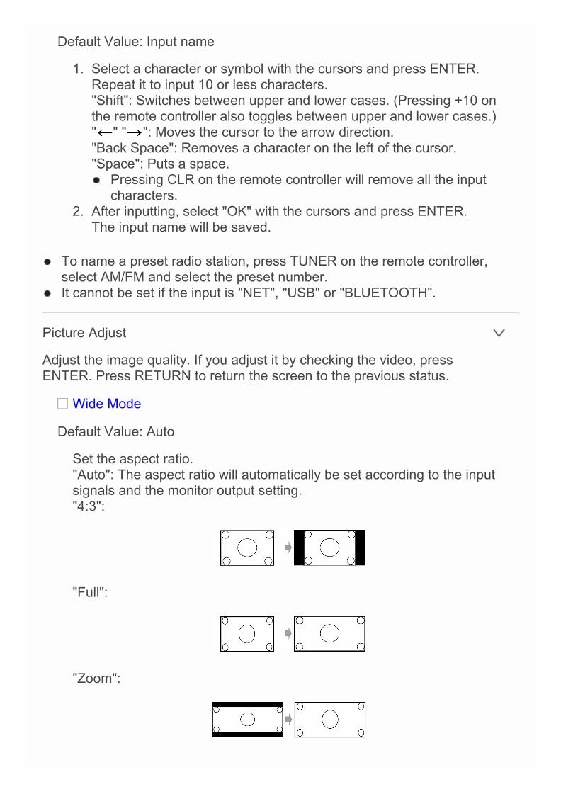
Default Value: Input name
1. Select a character or symbol with the cursors and press ENTER.Repeat it to input 10 or less characters."Shift": Switches between upper and lower cases. (Pressing +10 onthe remote controller also toggles between upper and lower cases.)" " " ": Moves the cursor to the arrow direction."Back Space": Removes a character on the left of the cursor."Space": Puts a space. Pressing CLR on the remote controller will remove all the input
characters.2. After inputting, select "OK" with the cursors and press ENTER.
The input name will be saved.
To name a preset radio station, press TUNER on the remote controller,select AM/FM and select the preset number.
It cannot be set if the input is "NET", "USB" or "BLUETOOTH".
Picture Adjust
Adjust the image quality. If you adjust it by checking the video, pressENTER. Press RETURN to return the screen to the previous status.
Wide Mode
Default Value: Auto
Set the aspect ratio."Auto": The aspect ratio will automatically be set according to the inputsignals and the monitor output setting."4:3":
"Full":
"Zoom":
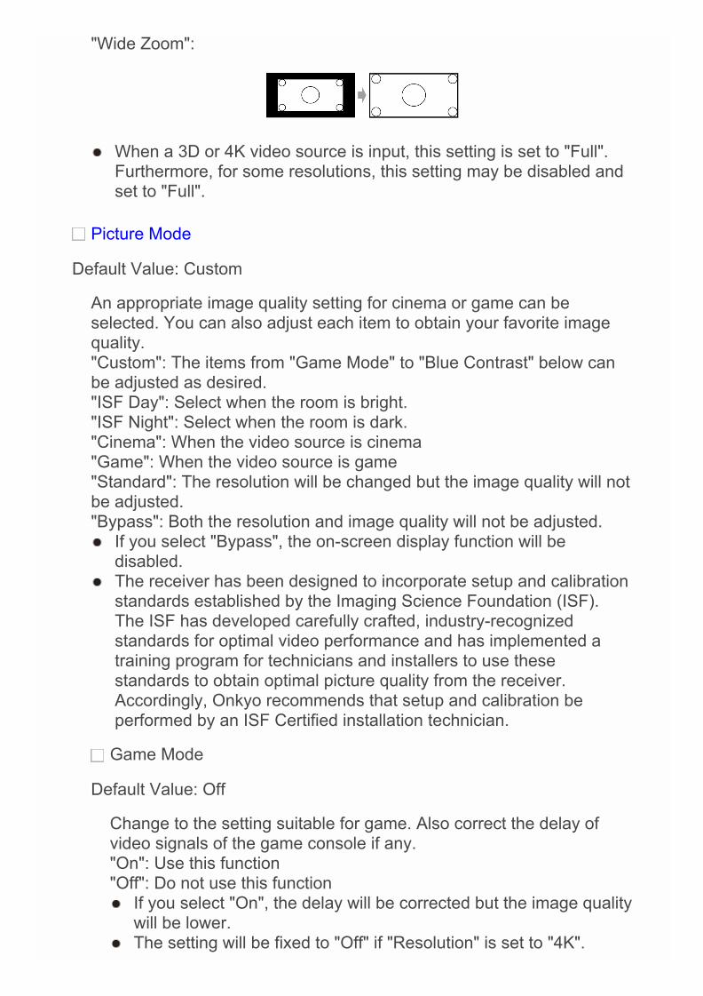
"Wide Zoom":
When a 3D or 4K video source is input, this setting is set to "Full".Furthermore, for some resolutions, this setting may be disabled andset to "Full".
Picture Mode
Default Value: Custom
An appropriate image quality setting for cinema or game can beselected. You can also adjust each item to obtain your favorite imagequality."Custom": The items from "Game Mode" to "Blue Contrast" below canbe adjusted as desired."ISF Day": Select when the room is bright."ISF Night": Select when the room is dark."Cinema": When the video source is cinema"Game": When the video source is game"Standard": The resolution will be changed but the image quality will notbe adjusted."Bypass": Both the resolution and image quality will not be adjusted. If you select "Bypass", the on-screen display function will be
disabled. The receiver has been designed to incorporate setup and calibration
standards established by the Imaging Science Foundation (ISF).The ISF has developed carefully crafted, industry-recognizedstandards for optimal video performance and has implemented atraining program for technicians and installers to use thesestandards to obtain optimal picture quality from the receiver.Accordingly, Onkyo recommends that setup and calibration beperformed by an ISF Certified installation technician.
Game Mode
Default Value: Off
Change to the setting suitable for game. Also correct the delay ofvideo signals of the game console if any."On": Use this function"Off": Do not use this function If you select "On", the delay will be corrected but the image quality
will be lower. The setting will be fixed to "Off" if "Resolution" is set to "4K".

Film Mode
Default Value: Auto
Change to the setting suitable for film."Auto": Image processing suitable for film will be executed."Video": "Film Mode" will not be applied and the input signals will beprocessed as video source.
Edge Enhancement
Default Value: Off
Adjust the sharpness of the outline of image. Select from "Off","Low", "Mid" (Middle), and "High". The setting will be fixed to "Off" if "Game Mode" is set to "On". When the horizontal resolution of the output video is 2,000 TV
lines or more, this setting is set to "Off".
Noise Reduction
Default Value: Off
Reduces the noise of the screen. Select from "Off", "Low", "Mid"(Middle), and "High". The setting will be fixed to "Off" if "Game Mode" is set to "On".
Resolution
Default Value: Through
Adjust the output resolution of the HDMI OUT jacks. The imageresolution will be converted to the value consistent with the resolutionsupported by your TV."Through": The output resolution is not converted and will be thesame as that of the input signals."Auto": The resolution will automatically be converted to theresolution supported by the TV."480p (480p/576p)", "720p", "1680×720p", "1080i", "1080p" or"2560×1080p": Select the desired resolution."4K": About four times as high resolution as 1080p (3840×2160 or4096×2160 pixels depending on the resolution supported by theconnected TV) The setting can be selected only when "Source" is selected for
"Resolution" which is shown in the section " 1. Input/OutputAssign" - "Monitor Out" - "Resolution".
If "4K" is selected, video signals may not be output to some typesof TVs. For details, see "Supported Video Resolution of HDMIOUT MAIN/SUB Jacks" in "Troubleshooting".
Brightness
Default Value: 0
Adjust brightness of the screen. Select a value from "-50" to "+50".
Contrast
Default Value: 0
Adjust contrast of the screen. Select a value from "-50" to "+50".
Hue
Default Value: 0
Correct hue of the screen. Select a value from "-50" to "+50".
Saturation
Default Value: 0
Adjust saturation of the screen. Select a value from "-50" to "+50".
Color Temperature
Default Value: Normal
Set color temperature of the screen. Select from "Warm", "Normal"and "Cool".
Gamma
Default Value: 0
Adjust the relative relation between the R (red), G (green) and B(blue) data signals of the input image and those of the output image.Select a value from "-3" to "+3".
Red Brightness
Default Value: 0
Adjust the brightness of red of the screen.Select a value from "-50" to "+50".
Red Contrast
Default Value: 0
Adjust the contrast of red of the screen.Select a value from "-50" to "+50".

Green Brightness
Default Value: 0
Adjust the brightness of green of the screen.Select a value from "-50" to "+50".
Green Contrast
Default Value: 0
Adjust the contrast of green of the screen.Select a value from "-50" to "+50".
Blue Brightness
Default Value: 0
Adjust the brightness of blue of the screen.Select a value from "-50" to "+50".
Blue Contrast
Default Value: 0
Adjust the contrast of blue of the screen.Select a value from "-50" to "+50".
If "NET", "USB" or "BLUETOOTH" is selected, the settings for "PictureAdjust" cannot be changed:
Press CLR on the remote controller if you return all the settings from"Game Mode" through "Blue Contrast" to their default value.
Audio Selector
Make the audio input setting. The setting can be separately set to each inputselector button. Select the input selector to configure.
Audio Selector
Default Value: –
Allows you to select prior input source."ARC": When giving priority to input signal from ARC compatible TV. The setting can be selected only when "7. Hardware Setup" -
"HDMI" - "Audio Return Channel" is set to "Auto" and also the"TV/CD" input is selected.
"HDMI": When giving priority to input signal from HDMI jacks The setting can be selected only when the input is assigned to the
HDMI IN jack in the "HDMI Input" setting."COAXIAL (Coaxial input)": When giving priority to input signal fromCOAXIAL IN jacks. The setting can be selected only when the input is assigned to the
COAXIAL jack in the "Digital Audio Input" setting."OPTICAL (Optical input)": When giving priority to input signal fromOPTICAL IN jacks. The setting can be selected only when the input is assigned to the
OPTICAL jack in the "Digital Audio Input" setting."Analog": To always output analog audio independently of the inputsignal
Fixed Mode
Default Value: Off
Specify an input signal when "HDMI", "COAXIAL (Coaxial input)", or"OPTICAL (Optical input)" is selected for "Audio Selector". Set thisitem if noise is produced, or truncation occurs at the beginning of atrack that follows a gap when playing PCM or DTS sources."Off": To play an analog signal when there is no digital signal."PCM": To fix the input source to PCM (except for MultichannelPCM)."DTS": To fix the input source to DTS (except for DTS-HD). Changing "Audio Selector" changes the setting to "Off".
The setting cannot be changed when "PHONO", "TUNER", "NET", "USB"or "BLUETOOTH" input is selected or the WHOLE HOUSE MODEfunction is on.
5.Listening Mode PresetYou can preset your favorite listening mode to each input. (For example, youcan always apply straight decode to the Dolby TrueHD source of Blu-rayDisc to play it in unchanged sound field.)When the list of input sources is displayed, set the signal type and listeningmode.Although it is possible to select the listening mode during playback, theselected mode will be reset when the unit enters standby mode.
Analog/PCM
Default Value: Last Valid
Set the listening mode for playing PCM signals of CD and analogsignals of record and cassette tape.
Mono/Multiplex Source
Default Value: Last Valid
Set the listening mode for playing Dolby Digital and other digital signalsrecorded in monaural or multiplex audio.
2ch Source
Default Value: Last Valid
Set the listening mode for playing Dolby Digital and other digital signalsrecorded in 2 channels.
Dolby D/Dolby D Plus/TrueHD
Default Value: Last Valid
Set the listening mode for playing Dolby Digital, Dolby Digital Plus andDolby TrueHD signals.
DTS/DTS-ES/DTS-HD
Advanced Settings
Default Value: Last Valid
Set the listening mode for playing digital audio signals in DTS and DTS-HD High Resolution formats. Select the listening mode specified forBlu-ray or such other DTS-HD Master Audio source.
Other Multich Source
Default Value: Last Valid
Set the listening mode for playing DSD signals of DVD-Audio andSuper Audio CD that are input from HDMI IN jack.
Available listening modes vary depending on the input signal. Setting "Last Valid" will always select the last selected mode. Only "Analog" can be set to the "TUNER" input. "Digital" and "TrueHD" can be set to the "NET" and "USB" inputs. Only "Digital" can be set to the "BLUETOOTH" input.

6.Miscellaneous
Volume Setup
Make the detailed volume setting of the unit.
Volume Display
Default Value: Absolute
Switch the volume display between the absolute value and relativevalue. The absolute value 82 is equivalent to the relative value 0dB."Absolute": Absolute value such as "0.5" to "99.5""Relative (THX)": Relative value such as "-81.5dB" and "+18.0dB" If the absolute value is set to "82.0", "82.0Ref" will appear on the
display and the "THX" indicator will flash.
Muting Level
Default Value: -∞dB
Set the volume lowered from the listening volume when muting is on.Select a value from "-∞dB", "-50dB" to "-10dB". (in 10dB increments)
Maximum Volume
Default Value: Off
Set the maximum value to avoid too high volume. Select a value from"Off", "50" to "99".
Power On Volume
Default Value: Last
Set the volume level of when the power is turned on. Select a valuefrom "Last" (Volume level before entering standby mode), "Min", "1" to"99" and "Max". You cannot set a higher value than that of "Maximum Volume".
Headphone Level
Advanced Settings
Default Value: 0dB
Adjust the volume level difference between speakers and headphones.Select a value between "-12dB" to "+12dB".
OSD Setup
Make the setting of on-screen display function that can display the settingmenu screen, volume operation screen and the like on the TV.
On Screen Display
Default Value: On
Set whether or not to display the On Screen Display (OSD) on the TV."On": The operation screen will be displayed on the TV."Off": The operation screen will not be displayed on the TV. The operation screen may not be displayed depending on the input
signal even if "On" is selected. If the operation screen is notdisplayed, change the resolution of the connected device.
Language
Default Value: English
Select the OSD language.
Screen Saver
Default Value: 3min
Set the time to start the OSD screen saver. Select a value from "3min","5min", "10min" and "Off".

7.Hardware Setup
Multi Zone
Zone 2 Out
Default Value: Fixed
Select which of the integrated amplifier in a separate room or this unitshould be used to adjust the volume when Zone 2 is active."Fixed": Adjust on the Integrated amplifier in a separate room"Variable": Adjust on the unit
Zone 2 Maximum Volume
Default Value: Off
Set the maximum value for Zone 2 to avoid too high volume. Select avalue from "Off", "50" to "99".
Zone 2 Power On Volume
Default Value: Last
Set the Zone 2 volume level of when the unit is turned on. Select avalue from "Last" (Volume level when the unit was turned off), "Min", "1"to "99" and "Max". You cannot set a higher value than that of "Zone 2 Maximum
Volume".
Zone 3 Out
Default Value: Fixed
Select which of the integrated amplifier in a separate room or this unitshould be used to adjust the volume when Zone 3 is active."Fixed": Adjust on the Integrated amplifier in a separate room"Variable": Adjust on the unit
Zone 3 Maximum Volume
Advanced Settings
Default Value: Off
Set the maximum value for Zone 3 to avoid too high volume. Select avalue from "Off", "50" to "99".
Zone 3 Power On Volume
Default Value: Last
Set the Zone 3 volume level of when the unit is turned on. Select avalue from "Last" (Volume level when the unit was turned off), "Min", "1"to "99" and "Max". You cannot set a higher value than that of "Zone 3 Maximum
Volume".
Tuner
AM/FM Frequency Step (North American model)
Default Value: 10kHz/200kHz
Select a frequency step depending on your area of residence.Select "10kHz/200kHz" or "9kHz/50kHz". When this setting is changed, all radio presets are deleted.
AM Frequency Step (European and Asian models)
Default Value: 9kHz
Select a frequency step depending on your area of residence.Select "10kHz" or "9kHz". When this setting is changed, all radio presets are deleted.
HDMI
HDMI CEC (RIHD)
Default Value: Off
Setting to "On" enables the input selection link and other link functionswith HDMI connected CEC compliant device."On": Use this function"Off": Do not use this function Depending on the TV set, a link may need to be configured on the
TV.
This function is effective only when the device is connected to theHDMI OUT MAIN terminal.
Setting to "On" and closing the on-screen menu displays the nameof the CEC-compatible components and "RIHD On" on the display.
Power consumption in standby mode may increase if "On" is set.(Depending on the TV status, the unit will enter the normal standbymode.)
If you operate the MASTER VOLUME control of the unit when thissetting is set to "On" and you are listening to the audio through thespeakers of your TV, audio will be output also from the speakersconnected to the unit. If you want to output from only either of them,change the unit or TV settings, or reduce the volume of the unit.
If abnormal operation occurs when you set the setting to "On", set itto "Off".
When connecting a non-CEC compatible component, or when youare not sure whether it is compatible, set the setting to "Off".
When changing this setting, turn off and then on again the power ofall connected components.
Control Monitor
Default Value: MAIN
Select the main room monitor or the separate room monitor for whichthe CEC link function is enabled when Zone function is used."MAIN": The CEC link function is enabled for the monitor in the mainroom."ZONE2": The CEC link function is enabled for the monitor in Zone 2. "MAIN" cannot be selected when " Monitor Out " is set to "SUB". "ZONE2" can be selected only when "Zone 2 Monitor Out" is set to
"Use". When "ZONE2" is selected in "Control Monitor", the power
consumption increases even when the unit is on standby. However,the increase in power consumption is kept to a minimum byautomatically entering the HYBRID STANDBY mode, where only theessential circuit is operating.
HDMI Through
Default Value: Off
You can display the video of an HDMI connected player on the TV evenif the unit is in standby mode. This setting is effective only for an inputselector to which an HDMI jack is assigned in "HDMI Input". It cannotbe set to any other input selector unless an HDMI jack is assigned to it."Off": The setting is disabled. Video of device connected to any jack willnot be displayed.

"BD/DVD", "CBL/SAT", "STB/DVR", "GAME", "PC", "AUX", "TV/CD","PHONO": Video of the device connected to the HDMI IN jack assignedto each input will be displayed on the TV."Last": Video of the device connected to the HDMI IN jack assigned tothe input selector that was selected immediately before the unit entersstandby mode will be displayed on the TV."Auto": Video of all the devices connected to the HDMI IN jacks will beoutput to the TV."Auto(Eco)": Video of all the devices connected to the HDMI IN jackswill be output to the TV. If you select this setting when using a CEC-compatible TV, you can reduce the power consumption in standbymode. In the following cases, the "Auto" and "Auto(Eco)" cannot be
selected:– "HDMI CEC (RIHD)" is set to "Off".– "HDMI CEC (RIHD)" is set to "On" and also "Control Monitor" is
set to "ZONE2". When "HDMI Through" is enabled, the power consumption
increases even when the unit is on standby. However, the increasein power consumption is kept to a minimum by automaticallyentering the HYBRID STANDBY mode, where only the essentialcircuit is operating.
When changing the setting, turn off and then on again the power ofall connected components.
Audio TV Out (MAIN)
Default Value: Off
You can enjoy audio through the speakers of the HDMI connected TVwhile this unit is on."On": Use this function"Off": Do not use this function If you select "On", set "HDMI CEC (RIHD)" to "Off." The setting is fixed to "Auto" if "HDMI CEC (RIHD)" is set to "On"
and "Control Monitor" is set to "MAIN". Listening mode cannot be changed if "Audio TV Out (MAIN)" is set
to "On" and audio is being output through the speakers of the TV. Depending on your TV set or input signal of the component, audio
may not output through the speakers of the TV even if this setting isset to "On". In such case, audio is output from the speakers of theunit.
If you operate the MASTER VOLUME control of the unit when"Audio TV Out (MAIN)" or "HDMI CEC (RIHD)" is set to "On" andyou are listening to the audio through the speakers of your TV, audiowill be output from the unit. If you do not want to output audio fromthe unit, change the unit or TV settings, or reduce the volume of the
unit. "Audio TV Out (MAIN)" is fixed to "Off" if "1. Input/Output Assign" -
"Monitor Out" - "Monitor Out" is set to "SUB".
Audio TV Out (SUB)
Default Value: Off
You can enjoy audio through the speakers of the HDMI connected TVwhile this unit is on."On": Use this function"Off": Do not use this function Listening mode cannot be changed while "Audio TV Out (SUB)" is
set to "On" and audio is being output through the speakers of theTV.
Depending on your TV set or input signal of the component, audiomay not output through the speakers of the TV even if this setting isset to "On". In such case, audio is output from the speakers of theunit.
If you operate the MASTER VOLUME control of the unit when"Audio TV Out (SUB)" is set to "On" and you are listening to theaudio through the speakers of your TV, audio will be output from theunit. If you do not want to output audio from the unit, change the unitor TV settings, or reduce the volume of the unit.
"Audio TV Out (SUB)" is fixed to "Off" if "1. Input/Output Assign" -"Monitor Out" - "Monitor Out" is set to "MAIN".
Audio Return Channel
Default Value: –
You can enjoy sound of the HDMI connected ARC compatible TVthrough the speakers connected to the unit. To use this function, set"HDMI CEC (RIHD)" to "On" in advance."Auto": When enjoying the TV sound through the speakers connectedto the unit"Off": When not using the ARC function Set "Control Monitor" to "MAIN" when changing this setting.
Lip Sync
Default Value: On
This setting automatically corrects any desynchronization between thevideo and audio signals based on data from the HDMI LipSynccompatible TV."On": Automatic correction will be enabled.
"Off": Automatic correction will be disabled.
InstaPrevueSub Window
Default Value: Multi
Change the preview display of the video input through HDMI, which willbe displayed using "InstaPrevue" in the HOME menu.Set how to display preview thumbnails."Multi": Displays all the thumbnails of HDMI IN 1, 2, 3, 4 and Front atonce."Single": Displays each thumbnail individually. Depending on the video source, the preview thumbnails configured
in "InstaPrevue" may not be displayed properly.
InstaPrevuePosition
Default Value: Bottom/Lower Right
Change the preview display of the video input through HDMI, which willbe displayed using "InstaPrevue" in the HOME menu.Set the position to display preview thumbnails.When "Multi" is selected for "Sub Window": Select from "Top", "Bottom","Left" and "Right".When "Single" is selected for "Sub Window": Select from "Upper Left","Upper Right", "Lower Left" and "Lower Right". Depending on the video source, the preview thumbnails configured
in "InstaPrevue" may not be displayed properly.
Auto Standby
Auto Standby
Default Value: On/Off
This setting places the unit on standby automatically after 20 minutes ofinactivity without any video or audio input."On": The unit will automatically enter standby mode ("ASb" will stay lit)."Off": The unit will not automatically enter standby mode. "Auto Standby" is appeared on the display and menu screen 30
seconds before the Auto Standby comes on. "Auto Standby" does not work when Zone 2/Zone 3 is active. Default values vary depending on the regions.

HDMI Through
Default Value: Off
Enable or disable "Auto Standby" while "HDMI Through" is on."On": The setting will be enabled."Off": The setting will be disabled. The setting cannot be changed, if "Auto Standby" is set to "Off".
When "HDMI Through" is used, the power consumption increases evenwhen the unit is on standby. However, the increase in power consumptionis kept to a minimum by automatically entering the HYBRID STANDBYmode, where only the essential circuit is operating.
Network
Make the network setting. When LAN is configured with a DHCP, set "DHCP" to "Enable" to
configure the setting automatically. ("Enable" is set by default) To assignfixed IP addresses to each components, you must set "DHCP" to"Disable" and assign an address to this unit in "IP Address" as well as setinformation related to your LAN, such as Subnet Mask and Gateway.
Network Standby
Default Value: Off
You can turn on the power of the unit via network using an applicationsuch as Onkyo Remote."On": Use this function"Off": Do not use this function When "Network Standby" is used, the power consumption increases
even when the unit is on standby. However, the increase in powerconsumption is kept to a minimum by automatically entering theHYBRID STANDBY mode, where only the essential circuit isoperating.
Wi-Fi
Default Value: Off(Wired)
Connect the unit to network via wireless LAN router."On": Wireless LAN connection"Off(Wired)": Wired LAN connection
Wi-Fi Setup
Default Value: –
You can configure wireless LAN settings by pressing ENTER when"Start" is displayed.
Wi-Fi Status
Default Value: –
The information of the connected access point will be displayed."SSID": SSID of the connected access point."Security": Security method of the connected access point."Signal": Signal strength of the connected access point."Status": Status of the connected access point.
MAC Address
Default Value: –
This is the MAC address of the AV receiver.This value is specific to the component and cannot be changed.
DHCP
Default Value: Enable
"Enable": Auto configuration by DHCP"Disable": Manual configuration without DHCP If selecting "Disable", you must set "IP Address", "Subnet Mask",
"Gateway", and "DNS Server" manually.
IP Address
Default Value: –
Displays/Sets the IP address.
Subnet Mask
Default Value: –
Displays/Sets the subnet mask.
Gateway
Default Value: –
Displays/Sets the gateway address.
DNS Server
Default Value: –
Displays/Sets the primary DNS server (primary).
Proxy URL
Default Value: –
Displays/Sets the proxy server URL.
Proxy Port
Default Value: –
Displays/Sets the proxy server port number when you enter "ProxyURL".
Network Check
Default Value: –
You can check the network connection.Press ENTER when "Start" is displayed.
Wait for a while if "Network" cannot be selected. It will appear when thenetwork function is started up.
Bluetooth
Bluetooth
Default Value: On
Select whether or not to use the Bluetooth function."On": Enables connection with a Bluetooth-enabled device by using theBluetooth function. Select "On" also when making various Bluetoothsettings."Off": When not using the Bluetooth function
Direct Change
Default Value: On
The input of the unit will automatically be switched to "BLUETOOTH"when connection is made from a Bluetooth-enabled device to the unit."On": The input will automatically become "BLUETOOTH" when aBluetooth-enabled device is connected.

"Off": The function is disabled. If the input is not switched automatically, set to "Off" and change the
input manually.
Auto Reconnect
Default Value: On
This function automatically reconnects to the Bluetooth-enabled deviceconnected last when you change the input selector to "BLUETOOTH"."On": Use this function"Off": Do not use this function This function may not work depending on your Bluetooth-enabled
device.
Wakeup via Bluetooth
Default Value: Off
This function wakes up the unit on standby by connecting a Bluetooth-enabled device."On": Use this function"Off": Do not use this function Setting to "On" increases the power consumption even when the unit
is on standby. However, the increase in power consumption is keptto a minimum by automatically entering the HYBRID STANDBYmode, where only the essential circuit is operating.
This setting "Wakeup via Bluetooth" is fixed to "Off" if "DirectChange" is set to "Off".
Pairing Information
Default Value: –
When paring is performed, the information of the previous pairingstored in this unit will be initialized.Pressing ENTER when "Clear" is displayed initializes the pairinginformation stored in this unit. This function does not initialize the pairing information on the
Bluetooth-enabled device. When pairing the unit again with thedevice, be sure to clear the pairing information on the Bluetooth-enabled device in advance. For information on how to clear thepairing information, refer to the Bluetooth-enabled device'sinstruction manual.
Device

Default Value: –
Displays the name of the Bluetooth-enabled device connected to theunit. The name is not displayed when "Status" is "Ready" and "Now
Pairing...".
Status
Default Value: –
Displays the status of the Bluetooth-enabled device connected to theunit."Ready": Not paired"Now Pairing...": Paired"Connected": Successfully connected
Wait for a while if "Bluetooth" cannot be selected. It will appear when thenetwork function is started up.
Firmware Update
Update Notice
Default Value: Enable
Availability of a firmware update will be notified via network."Enable": Notify updates"Disable": Do not notify updates
Version
Default Value: –
The current firmware version will be displayed.
Update via NET
Default Value: –
Press ENTER to select when you want to update the firmware vianetwork. You will not be able to select this setting if you do not have
Internet access or there is nothing to update.
Update via USB

Default Value: –
Press ENTER to select when you want to update the firmware viaUSB. You will not be able to select this setting if a USB storage device
is not connected or there is nothing to update in the USB storagedevice.
Wait for a while if "Firmware Update" cannot be selected. It will appearwhen the network function is started up.
Initial Setup
You can make the initial setup from the setup menu. Wait for a while if "Initial Setup" cannot be selected. It will appear when
the network function is started up.
8.Remote Controller Setup
Remote ID
Default Value: 1
Select an ID for the unit's remote controller from "1", "2", and "3" toprevent interference between the unit and other Onkyo componentsthat are installed in the same room. After changing the ID on the mainunit, change the ID on the remote controller accordingly with thefollowing procedure.1. While holding down RECEIVER, press Q SETUP for about 3
seconds until RECEIVER button the remote indicator lights.2. With the number buttons, press one of 1, 2, and 3. RECEIVER
button flashes twice.
Remote Mode Setup
Default Value: –
Input and register the remote controller code of other devices. For registration of the remote control code, refer to "Operating Other
Components with the Remote Controller".
Advanced Settings

9.Lock Setup
Setup
Default Value: Unlocked
The Setup menu will be locked to protect the settings."Locked": The menu is locked."Unlocked": The menu is unlocked.
Advanced Settings
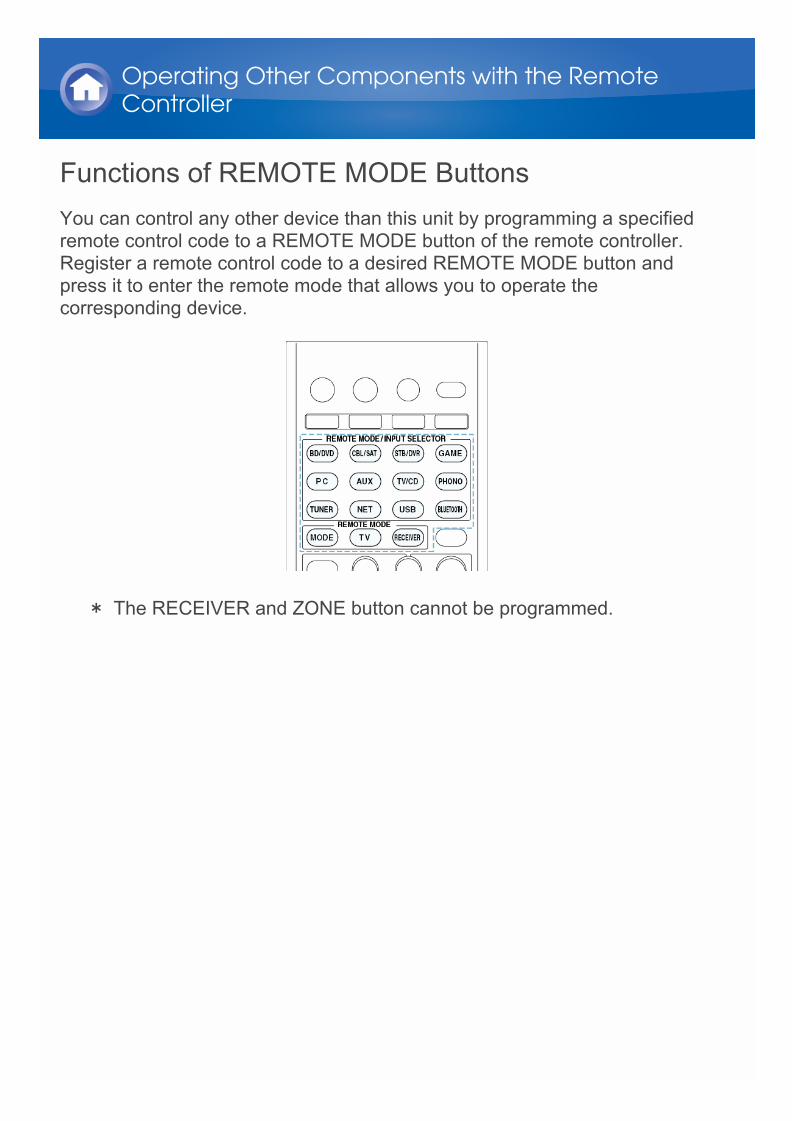
Functions of REMOTE MODE ButtonsYou can control any other device than this unit by programming a specifiedremote control code to a REMOTE MODE button of the remote controller.Register a remote control code to a desired REMOTE MODE button andpress it to enter the remote mode that allows you to operate thecorresponding device.
* The RECEIVER and ZONE button cannot be programmed.
Operating Other Components with the RemoteController

Programming Remote Control CodesFor information on the configuration and operation of Onkyo componentswith RI jack, refer to "Connecting and Operating Onkyo RI Components".Furthermore, the following REMOTE MODE buttons are preprogrammedwith remote control codes.
BD/DVD: Onkyo Blu-ray Disc/DVD playerTV/CD: Onkyo CD playerSTB/DVR: Apple TV
Searching in the Setup Menu
You can search a remote control code and register it to a desired REMOTEMODE button in the unit's Setup menu.
1. Press RECEIVER and then press HOME on the remote controller.
2. Select "Setup" with the cursors and press ENTER.3. With the cursors, select "8. Remote Controller Setup" - "Remote Mode
Setup" and press ENTER.4. With the cursors, select the remote mode for which you want to search a
remote control code and press ENTER to display the category selectionscreen.
5. Select the target category with the cursors, and then press ENTER todisplay the brand name input screen.
6. Select a character with the cursors and press ENTER. Repeat it to enter
Operating Other Components with the RemoteController
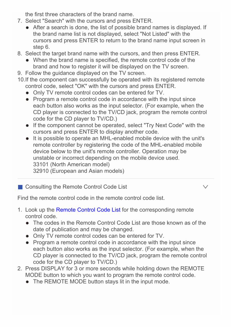
the first three characters of the brand name.7. Select "Search" with the cursors and press ENTER.
After a search is done, the list of possible brand names is displayed. Ifthe brand name list is not displayed, select "Not Listed" with thecursors and press ENTER to return to the brand name input screen instep 6.
8. Select the target brand name with the cursors, and then press ENTER. When the brand name is specified, the remote control code of the
brand and how to register it will be displayed on the TV screen.9. Follow the guidance displayed on the TV screen.10.If the component can successfully be operated with its registered remote
control code, select "OK" with the cursors and press ENTER. Only TV remote control codes can be entered for TV. Program a remote control code in accordance with the input since
each button also works as the input selector. (For example, when theCD player is connected to the TV/CD jack, program the remote controlcode for the CD player to TV/CD.)
If the component cannot be operated, select "Try Next Code" with thecursors and press ENTER to display another code.
It is possible to operate an MHL-enabled mobile device with the unit'sremote controller by registering the code of the MHL-enabled mobiledevice below to the unit's remote controller. Operation may beunstable or incorrect depending on the mobile device used.33101 (North American model)32910 (European and Asian models)
Consulting the Remote Control Code List
Find the remote control code in the remote control code list.
1. Look up the Remote Control Code List for the corresponding remotecontrol code. The codes in the Remote Control Code List are those known as of the
date of publication and may be changed. Only TV remote control codes can be entered for TV. Program a remote control code in accordance with the input since
each button also works as the input selector. (For example, when theCD player is connected to the TV/CD jack, program the remote controlcode for the CD player to TV/CD.)
2. Press DISPLAY for 3 or more seconds while holding down the REMOTEMODE button to which you want to program the remote control code. The REMOTE MODE button stays lit in the input mode.
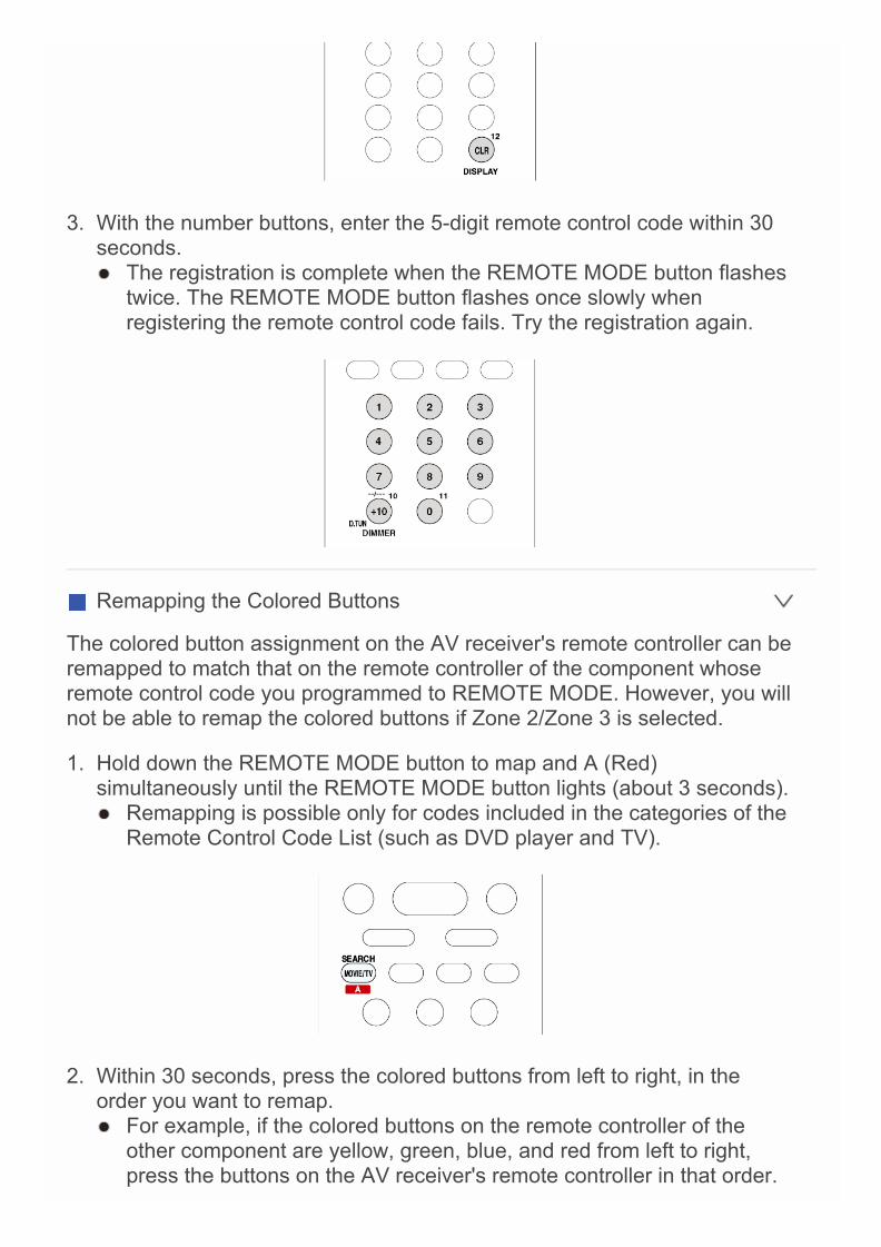
3. With the number buttons, enter the 5-digit remote control code within 30seconds. The registration is complete when the REMOTE MODE button flashes
twice. The REMOTE MODE button flashes once slowly whenregistering the remote control code fails. Try the registration again.
Remapping the Colored Buttons
The colored button assignment on the AV receiver's remote controller can beremapped to match that on the remote controller of the component whoseremote control code you programmed to REMOTE MODE. However, you willnot be able to remap the colored buttons if Zone 2/Zone 3 is selected.
1. Hold down the REMOTE MODE button to map and A (Red)simultaneously until the REMOTE MODE button lights (about 3 seconds). Remapping is possible only for codes included in the categories of the
Remote Control Code List (such as DVD player and TV).
2. Within 30 seconds, press the colored buttons from left to right, in theorder you want to remap. For example, if the colored buttons on the remote controller of the
other component are yellow, green, blue, and red from left to right,press the buttons on the AV receiver's remote controller in that order.
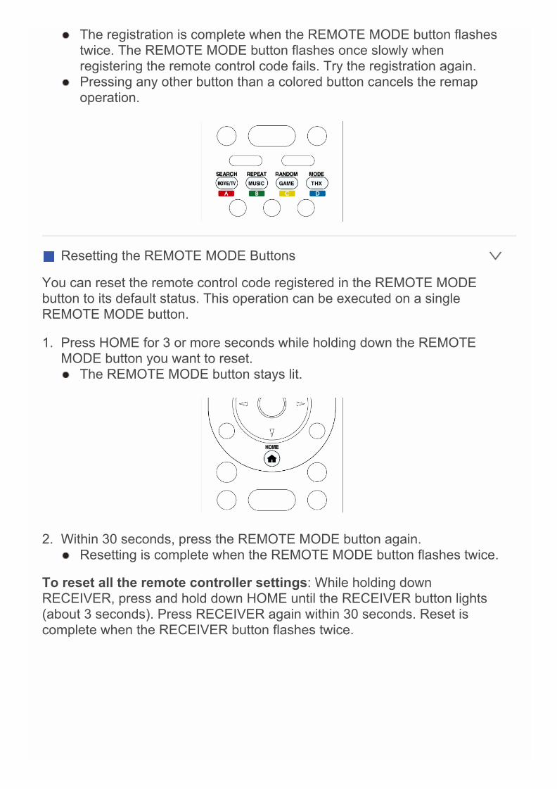
The registration is complete when the REMOTE MODE button flashestwice. The REMOTE MODE button flashes once slowly whenregistering the remote control code fails. Try the registration again.
Pressing any other button than a colored button cancels the remapoperation.
Resetting the REMOTE MODE Buttons
You can reset the remote control code registered in the REMOTE MODEbutton to its default status. This operation can be executed on a singleREMOTE MODE button.
1. Press HOME for 3 or more seconds while holding down the REMOTEMODE button you want to reset. The REMOTE MODE button stays lit.
2. Within 30 seconds, press the REMOTE MODE button again. Resetting is complete when the REMOTE MODE button flashes twice.
To reset all the remote controller settings: While holding downRECEIVER, press and hold down HOME until the RECEIVER button lights(about 3 seconds). Press RECEIVER again within 30 seconds. Reset iscomplete when the RECEIVER button flashes twice.
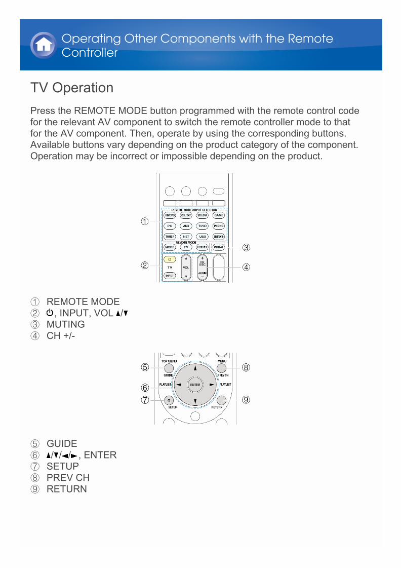
TV OperationPress the REMOTE MODE button programmed with the remote control codefor the relevant AV component to switch the remote controller mode to thatfor the AV component. Then, operate by using the corresponding buttons.Available buttons vary depending on the product category of the component.Operation may be incorrect or impossible depending on the product.
1 REMOTE MODE2 , INPUT, VOL /3 MUTING4 CH +/-
5 GUIDE6 / / / , ENTER7 SETUP8 PREV CH9 RETURN
Operating Other Components with the RemoteController
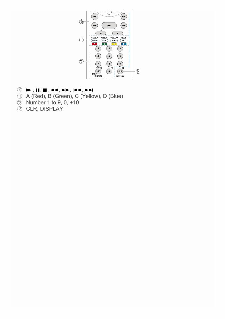
F , , , , , , G A (Red), B (Green), C (Yellow), D (Blue)H Number 1 to 9, 0, +10I CLR, DISPLAY
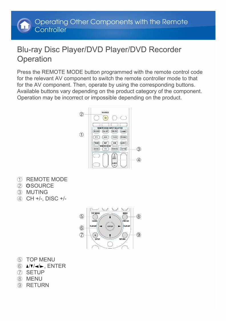
Blu-ray Disc Player/DVD Player/DVD RecorderOperationPress the REMOTE MODE button programmed with the remote control codefor the relevant AV component to switch the remote controller mode to thatfor the AV component. Then, operate by using the corresponding buttons.Available buttons vary depending on the product category of the component.Operation may be incorrect or impossible depending on the product.
1 REMOTE MODE2 SOURCE3 MUTING4 CH +/-, DISC +/-
5 TOP MENU6 / / / , ENTER7 SETUP8 MENU9 RETURN
Operating Other Components with the RemoteController
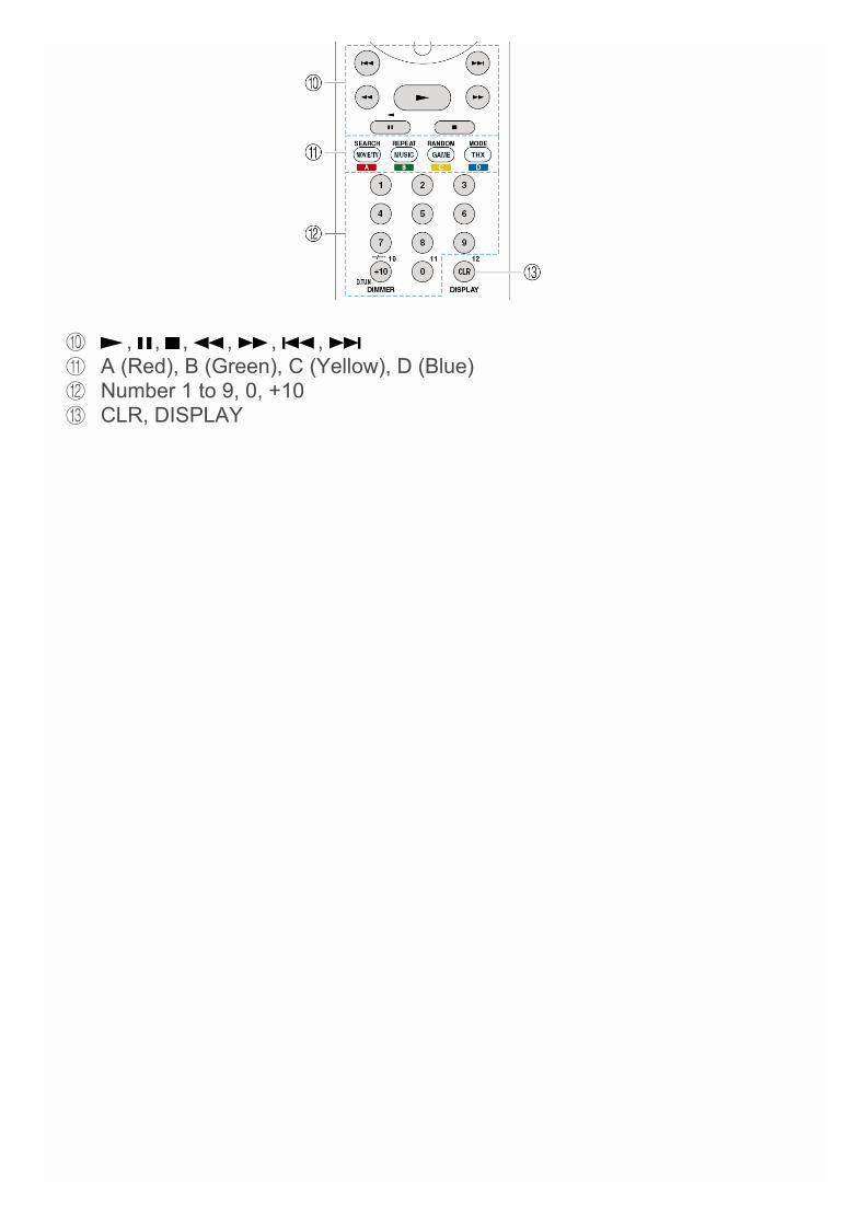
F , , , , , , G A (Red), B (Green), C (Yellow), D (Blue)H Number 1 to 9, 0, +10I CLR, DISPLAY
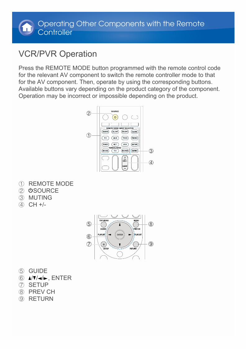
VCR/PVR OperationPress the REMOTE MODE button programmed with the remote control codefor the relevant AV component to switch the remote controller mode to thatfor the AV component. Then, operate by using the corresponding buttons.Available buttons vary depending on the product category of the component.Operation may be incorrect or impossible depending on the product.
1 REMOTE MODE2 SOURCE3 MUTING4 CH +/-
5 GUIDE6 / / / , ENTER7 SETUP8 PREV CH9 RETURN
Operating Other Components with the RemoteController

F , , , , , , G Number 1 to 9, 0, +10H CLR, DISPLAY

Satellite Receiver/Cable Receiver OperationPress the REMOTE MODE button programmed with the remote control codefor the relevant AV component to switch the remote controller mode to thatfor the AV component. Then, operate by using the corresponding buttons.Available buttons vary depending on the product category of the component.Operation may be incorrect or impossible depending on the product.
1 REMOTE MODE2 SOURCE3 MUTING4 CH +/-
5 GUIDE6 / / / , ENTER7 SETUP8 PREV CH9 RETURN
Operating Other Components with the RemoteController

F , , , , , , G A (Red), B (Green), C (Yellow), D (Blue)H Number 1 to 9, 0, +10I CLR, DISPLAY

CD Player OperationPress the REMOTE MODE button programmed with the remote control codefor the relevant AV component to switch the remote controller mode to thatfor the AV component. Then, operate by using the corresponding buttons.Available buttons vary depending on the product category of the component.Operation may be incorrect or impossible depending on the product.
1 REMOTE MODE2 SOURCE3 MUTING4 DISC +/-
5 / / / , ENTER6 SETUP
Operating Other Components with the RemoteController

7 , , , , , , 8 SEARCH, REPEAT, RANDOM, MODE9 Number 1 to 9, 0, +10F CLR, DISPLAY
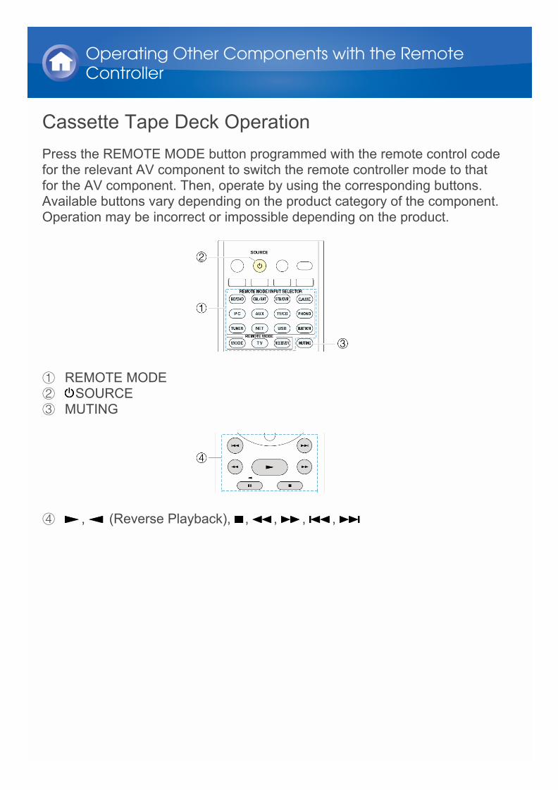
Cassette Tape Deck OperationPress the REMOTE MODE button programmed with the remote control codefor the relevant AV component to switch the remote controller mode to thatfor the AV component. Then, operate by using the corresponding buttons.Available buttons vary depending on the product category of the component.Operation may be incorrect or impossible depending on the product.
1 REMOTE MODE2 SOURCE3 MUTING
4 , (Reverse Playback), , , , ,
Operating Other Components with the RemoteController

To Operate CEC-compatible ComponentsThe TV and BD/DVD buttons on the remote controller are preprogrammedwith remote control codes for linked operation of some CEC(ConsumerElectronics Control)-compatible TV sets and Blu-ray Disk players. Byconnecting to the unit via HDMI, you may operate them using the AVreceiver's remote controller. If you cannot operate your CEC-compatible component, program one of
the following remote control codes to the TV or BD/DVD button.TV: 11807/13100/13500 (CEC-compatible TV)BD/DVD: 32910/33101/33501/31612 (CEC-compatible BD/DVD player)
Operating Other Components with the RemoteController
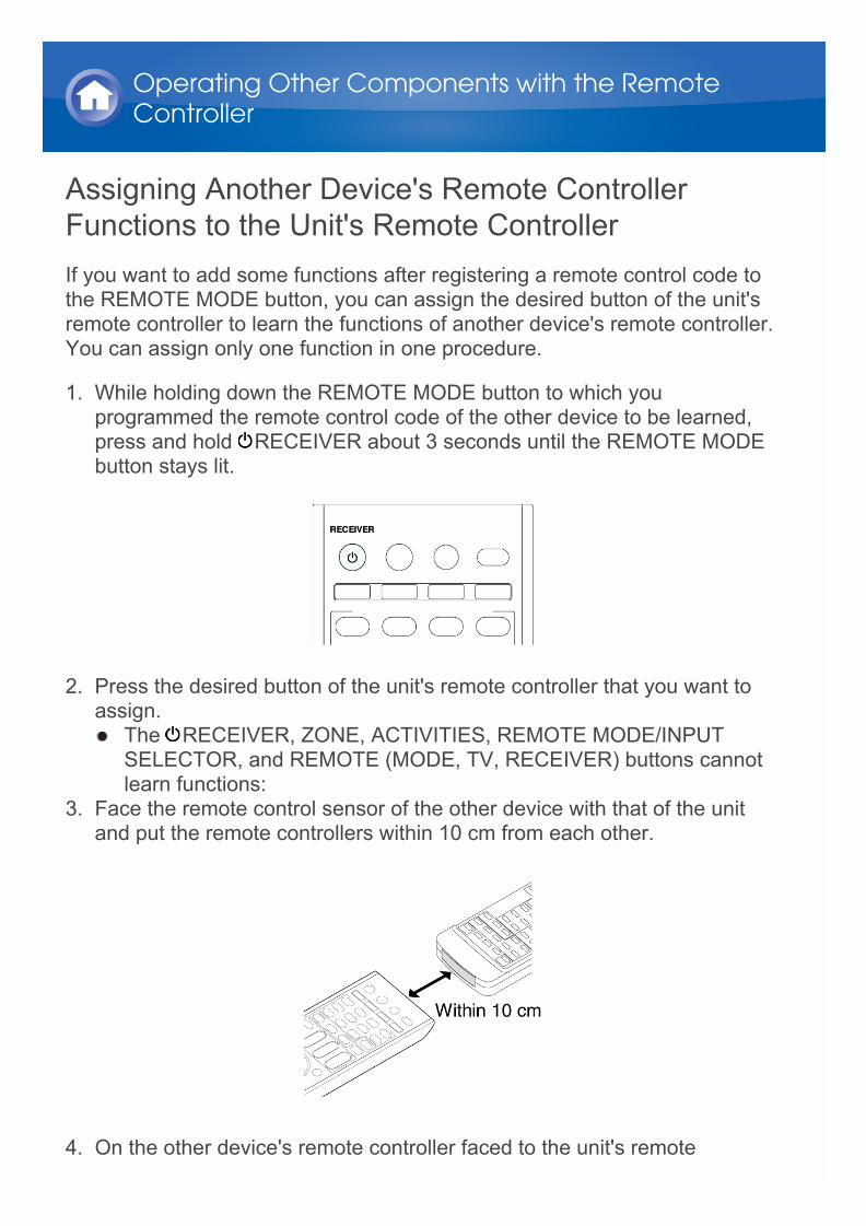
Assigning Another Device's Remote ControllerFunctions to the Unit's Remote ControllerIf you want to add some functions after registering a remote control code tothe REMOTE MODE button, you can assign the desired button of the unit'sremote controller to learn the functions of another device's remote controller.You can assign only one function in one procedure.
1. While holding down the REMOTE MODE button to which youprogrammed the remote control code of the other device to be learned,press and hold RECEIVER about 3 seconds until the REMOTE MODEbutton stays lit.
2. Press the desired button of the unit's remote controller that you want toassign. The RECEIVER, ZONE, ACTIVITIES, REMOTE MODE/INPUT
SELECTOR, and REMOTE (MODE, TV, RECEIVER) buttons cannotlearn functions:
3. Face the remote control sensor of the other device with that of the unitand put the remote controllers within 10 cm from each other.
4. On the other device's remote controller faced to the unit's remote
Operating Other Components with the RemoteController
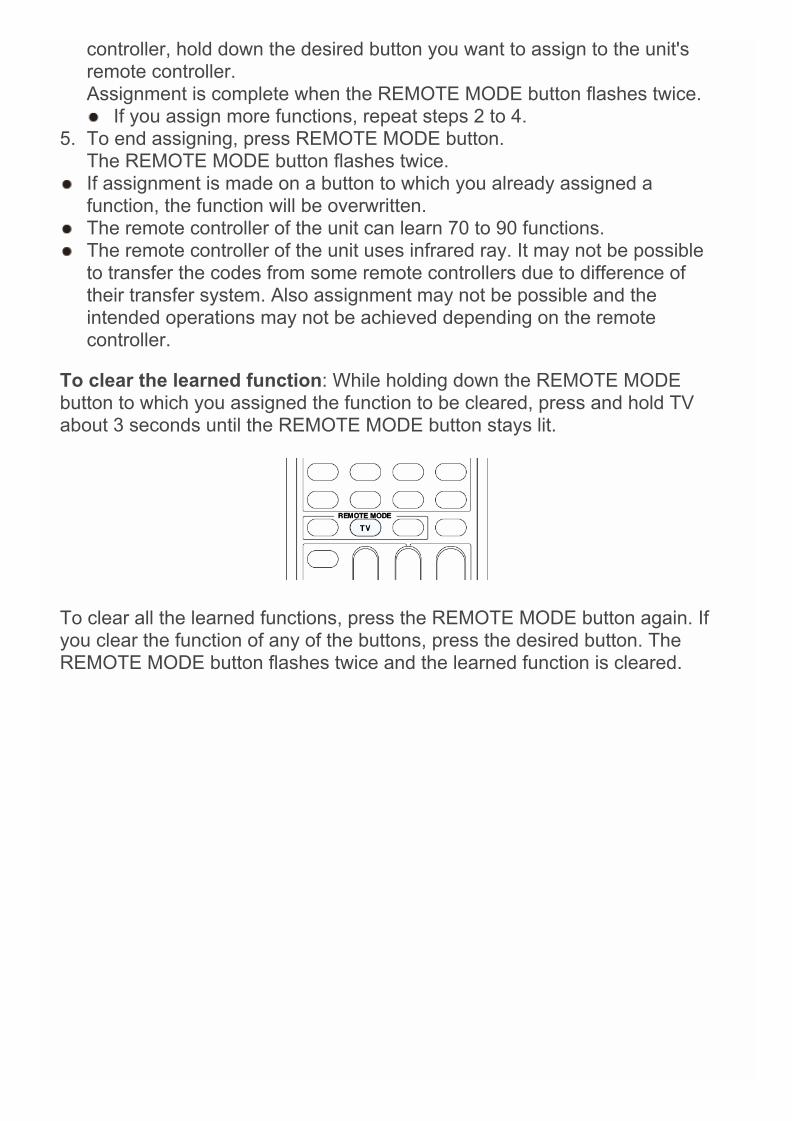
controller, hold down the desired button you want to assign to the unit'sremote controller.Assignment is complete when the REMOTE MODE button flashes twice. If you assign more functions, repeat steps 2 to 4.
5. To end assigning, press REMOTE MODE button.The REMOTE MODE button flashes twice.
If assignment is made on a button to which you already assigned afunction, the function will be overwritten.
The remote controller of the unit can learn 70 to 90 functions. The remote controller of the unit uses infrared ray. It may not be possible
to transfer the codes from some remote controllers due to difference oftheir transfer system. Also assignment may not be possible and theintended operations may not be achieved depending on the remotecontroller.
To clear the learned function: While holding down the REMOTE MODEbutton to which you assigned the function to be cleared, press and hold TVabout 3 seconds until the REMOTE MODE button stays lit.
To clear all the learned functions, press the REMOTE MODE button again. Ifyou clear the function of any of the buttons, press the desired button. TheREMOTE MODE button flashes twice and the learned function is cleared.
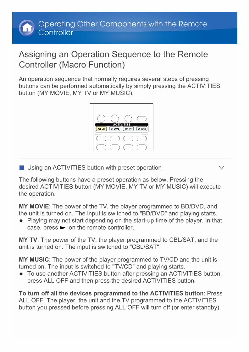
Assigning an Operation Sequence to the RemoteController (Macro Function)An operation sequence that normally requires several steps of pressingbuttons can be performed automatically by simply pressing the ACTIVITIESbutton (MY MOVIE, MY TV or MY MUSIC).
Using an ACTIVITIES button with preset operation
The following buttons have a preset operation as below. Pressing thedesired ACTIVITIES button (MY MOVIE, MY TV or MY MUSIC) will executethe operation.
MY MOVIE: The power of the TV, the player programmed to BD/DVD, andthe unit is turned on. The input is switched to "BD/DVD" and playing starts. Playing may not start depending on the start-up time of the player. In that
case, press on the remote controller.
MY TV: The power of the TV, the player programmed to CBL/SAT, and theunit is turned on. The input is switched to "CBL/SAT".
MY MUSIC: The power of the player programmed to TV/CD and the unit isturned on. The input is switched to "TV/CD" and playing starts. To use another ACTIVITIES button after pressing an ACTIVITIES button,
press ALL OFF and then press the desired ACTIVITIES button.
To turn off all the devices programmed to the ACTIVITIES button: PressALL OFF. The player, the unit and the TV programmed to the ACTIVITIESbutton you pressed before pressing ALL OFF will turn off (or enter standby).
Operating Other Components with the RemoteController
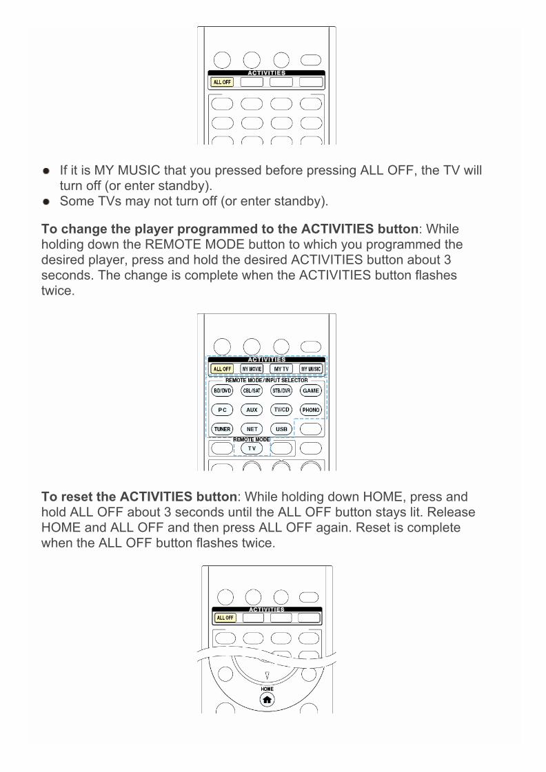
If it is MY MUSIC that you pressed before pressing ALL OFF, the TV willturn off (or enter standby).
Some TVs may not turn off (or enter standby).
To change the player programmed to the ACTIVITIES button: Whileholding down the REMOTE MODE button to which you programmed thedesired player, press and hold the desired ACTIVITIES button about 3seconds. The change is complete when the ACTIVITIES button flashestwice.
To reset the ACTIVITIES button: While holding down HOME, press andhold ALL OFF about 3 seconds until the ALL OFF button stays lit. ReleaseHOME and ALL OFF and then press ALL OFF again. Reset is completewhen the ALL OFF button flashes twice.
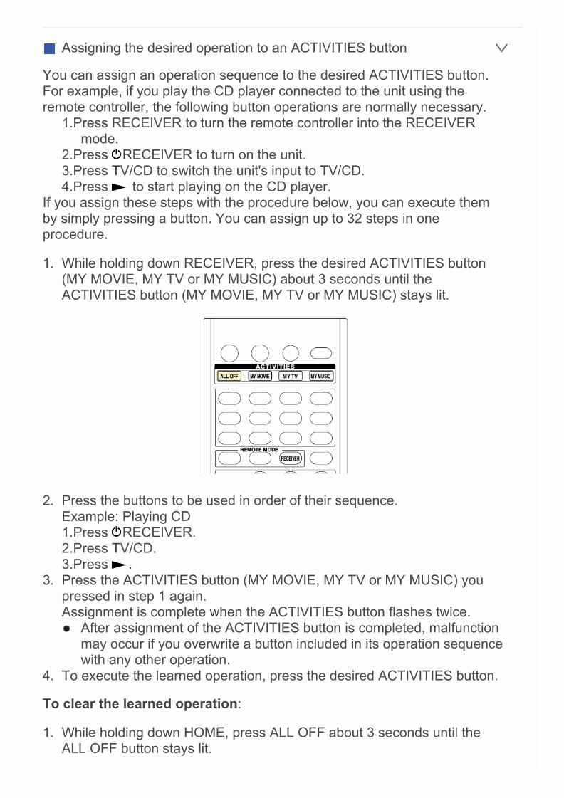
Assigning the desired operation to an ACTIVITIES button
You can assign an operation sequence to the desired ACTIVITIES button.For example, if you play the CD player connected to the unit using theremote controller, the following button operations are normally necessary.
1.Press RECEIVER to turn the remote controller into the RECEIVERmode.
2.Press RECEIVER to turn on the unit.3.Press TV/CD to switch the unit's input to TV/CD.4.Press to start playing on the CD player.
If you assign these steps with the procedure below, you can execute themby simply pressing a button. You can assign up to 32 steps in oneprocedure.
1. While holding down RECEIVER, press the desired ACTIVITIES button(MY MOVIE, MY TV or MY MUSIC) about 3 seconds until theACTIVITIES button (MY MOVIE, MY TV or MY MUSIC) stays lit.
2. Press the buttons to be used in order of their sequence.Example: Playing CD1.Press RECEIVER.2.Press TV/CD.3.Press .
3. Press the ACTIVITIES button (MY MOVIE, MY TV or MY MUSIC) youpressed in step 1 again.Assignment is complete when the ACTIVITIES button flashes twice. After assignment of the ACTIVITIES button is completed, malfunction
may occur if you overwrite a button included in its operation sequencewith any other operation.
4. To execute the learned operation, press the desired ACTIVITIES button.
To clear the learned operation:
1. While holding down HOME, press ALL OFF about 3 seconds until theALL OFF button stays lit.

2. Press ALL OFF again to clear.The ALL OFF button flashes twice.
The operation programmed to the ACTIVITIES button returns to thepreset operation after the learned operation is cleared.

Bi-AmpingIt is possible to connect speakers supporting bi-amping to improve quality ofthe bass and treble. Up to 9.2 ch will be played in bi-amping.
Connections
1. Connect as below using the FRONT terminals and HEIGHT 1 (Bi-AMP)terminals.
2. Turn the unit on and make the bi-amping setting.1 After pressing RECEIVER, press HOME on the remote controller.2 Select "Setup" with the cursors and press ENTER.3 With the cursors, select "2. Speaker Setup" - "Speaker Settings" -
"Front Speakers Type".4 Select "Bi-Amp" with the cursors.
Before bi-amping, be sure to remove the short-circuit connectorthat connects the tweeter (treble) terminal and the woofer (bass)terminal.
Use speakers supporting bi-amping only. For details, refer to thespeakers' instruction manual.
Advanced Speaker Connection
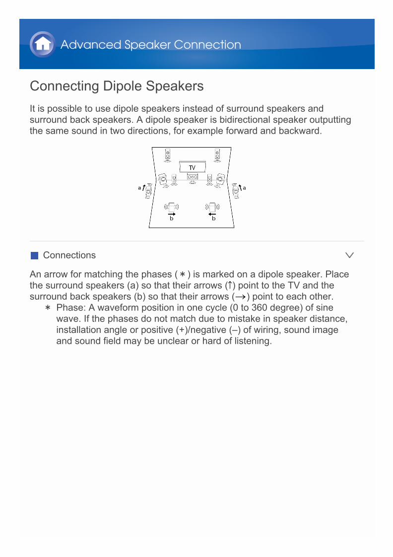
Connecting Dipole SpeakersIt is possible to use dipole speakers instead of surround speakers andsurround back speakers. A dipole speaker is bidirectional speaker outputtingthe same sound in two directions, for example forward and backward.
Connections
An arrow for matching the phases (*) is marked on a dipole speaker. Placethe surround speakers (a) so that their arrows ( ) point to the TV and thesurround back speakers (b) so that their arrows ( ) point to each other.
* Phase: A waveform position in one cycle (0 to 360 degree) of sinewave. If the phases do not match due to mistake in speaker distance,installation angle or positive (+)/negative (–) of wiring, sound imageand sound field may be unclear or hard of listening.
Advanced Speaker Connection
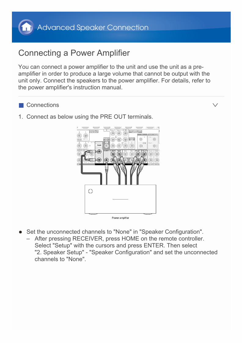
Connecting a Power AmplifierYou can connect a power amplifier to the unit and use the unit as a pre-amplifier in order to produce a large volume that cannot be output with theunit only. Connect the speakers to the power amplifier. For details, refer tothe power amplifier's instruction manual.
Connections
1. Connect as below using the PRE OUT terminals.
Set the unconnected channels to "None" in "Speaker Configuration".– After pressing RECEIVER, press HOME on the remote controller.
Select "Setup" with the cursors and press ENTER. Then select"2. Speaker Setup" - "Speaker Configuration" and set the unconnectedchannels to "None".
Advanced Speaker Connection

About RI FunctionConnecting an Onkyo component with RI jack such as the separately sold RIDock to the unit by using an RI cable and an analog audio (RCA) cableenables the following RI functions:
System On/Auto Power On: Starting playback on a component connectedvia RI when the unit is on standby mode, automatically turns on the unit toselect the relevant component as its input source.
Direct Change: When playback is started on a component connected via RI,the unit selects that component as the input source.
Remote Controller Operation: Allows you to operate RI-compatible Onkyocomponents using the AV receiver's remote controller. Point the remotecontroller at remote control sensor of the unit. This operation is possible onlywhen the RI remote control code is programmed.
Some components may not support all RI functions. These functions do not work when Zone 2/Zone 3 is turned on. For information on the RI functions, also refer to each component's
instruction manual.
Connecting and Operating Onkyo RI Components

RI Connection and Setting
Connect an Onkyo component with RI jack to this unit using an RI cable andan analog audio (RCA) cable. For details, refer to the instruction manual ofthe component with RI jack. The RI cable can be connected in any order.When there are two RI jacks, both jacks work in the same way and areinterchangeable.To connect the RI Dock or cassette tape deck via RI, you must:
Rename the input selector
To make the RI functions work, you must rename the input selectors on theunit. Press TV/CD or GAME to display "TV/CD" or "GAME" on the main unitdisplay. Then press and hold TV/CD or GAME 3 seconds or more to switchthe display to "DOCK" or "TAPE".
Program the RI remote control code
Program the remote control code to any REMOTE MODE button on theremote controller. This will allow you to operate the component by pointingthe remote controller at the unit instead of the component.
1. Press DISPLAY for 3 or more seconds while holding down the REMOTEMODE button to which you want to program the remote control code. The REMOTE MODE button stays lit.
Connecting and Operating Onkyo RI Components
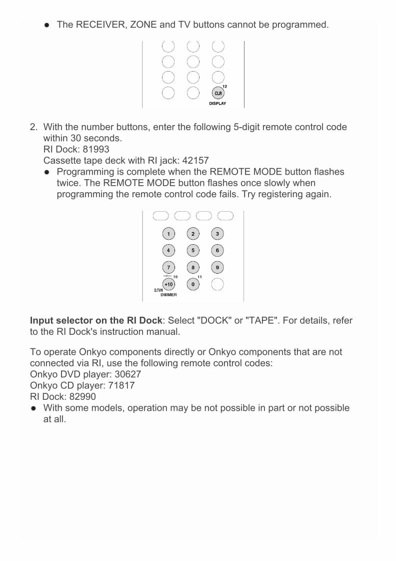
The RECEIVER, ZONE and TV buttons cannot be programmed.
2. With the number buttons, enter the following 5-digit remote control codewithin 30 seconds.RI Dock: 81993Cassette tape deck with RI jack: 42157 Programming is complete when the REMOTE MODE button flashes
twice. The REMOTE MODE button flashes once slowly whenprogramming the remote control code fails. Try registering again.
Input selector on the RI Dock: Select "DOCK" or "TAPE". For details, referto the RI Dock's instruction manual.
To operate Onkyo components directly or Onkyo components that are notconnected via RI, use the following remote control codes:Onkyo DVD player: 30627Onkyo CD player: 71817RI Dock: 82990 With some models, operation may be not possible in part or not possible
at all.
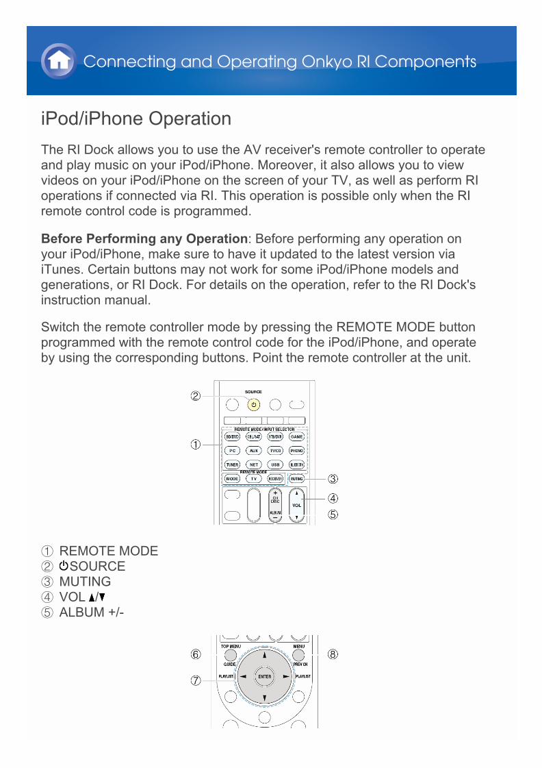
iPod/iPhone OperationThe RI Dock allows you to use the AV receiver's remote controller to operateand play music on your iPod/iPhone. Moreover, it also allows you to viewvideos on your iPod/iPhone on the screen of your TV, as well as perform RIoperations if connected via RI. This operation is possible only when the RIremote control code is programmed.
Before Performing any Operation: Before performing any operation onyour iPod/iPhone, make sure to have it updated to the latest version viaiTunes. Certain buttons may not work for some iPod/iPhone models andgenerations, or RI Dock. For details on the operation, refer to the RI Dock'sinstruction manual.
Switch the remote controller mode by pressing the REMOTE MODE buttonprogrammed with the remote control code for the iPod/iPhone, and operateby using the corresponding buttons. Point the remote controller at the unit.
1 REMOTE MODE2 SOURCE3 MUTING4 VOL /5 ALBUM +/-
Connecting and Operating Onkyo RI Components

6 TOP MENU7 / / / , ENTER, PLAYLIST /8 MENU
9 , , , , , , F REPEAT, RANDOMG MODEH DISPLAY
Pressing DISPLAY turns on the backlight for a few seconds. MODE allows you to use the Resume function to resume playing from the
song that was playing when you removed your iPod/iPhone from the DS-A2 RI Dock.
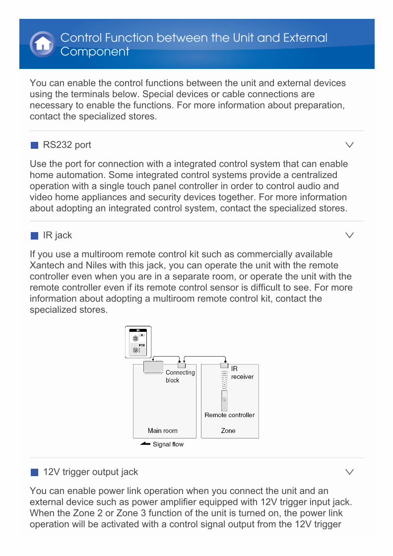
You can enable the control functions between the unit and external devicesusing the terminals below. Special devices or cable connections arenecessary to enable the functions. For more information about preparation,contact the specialized stores.
RS232 port
Use the port for connection with a integrated control system that can enablehome automation. Some integrated control systems provide a centralizedoperation with a single touch panel controller in order to control audio andvideo home appliances and security devices together. For more informationabout adopting an integrated control system, contact the specialized stores.
IR jack
If you use a multiroom remote control kit such as commercially availableXantech and Niles with this jack, you can operate the unit with the remotecontroller even when you are in a separate room, or operate the unit with theremote controller even if its remote control sensor is difficult to see. For moreinformation about adopting a multiroom remote control kit, contact thespecialized stores.
12V trigger output jack
You can enable power link operation when you connect the unit and anexternal device such as power amplifier equipped with 12V trigger input jack.When the Zone 2 or Zone 3 function of the unit is turned on, the power linkoperation will be activated with a control signal output from the 12V trigger
Control Function between the Unit and ExternalComponent

output jack. The maximum control signal is 12V/150 mA for Zone 2 and12V/25 mA for Zone 3. For connection, use a monaural mini plug cable.
About Firmware UpdateThere are two methods for updating the firmware: via network and via USB.Use the one that best suits your environment. For the latest information on updates, visit the Onkyo website. Before updating, make sure that the speaker setup microphone is not
connected. During an update, do not
– Disconnect and reconnect any cable, USB storage device, speakersetup microphone or headphones, or perform any operation on thecomponent such as turn off its power
– Access to this unit from a PC or smartphone using Android application The update may take about 20 minutes to complete for either method: via
network or via USB.Furthermore, existing settings are guaranteed regardless of the methodused for update.
Disclaimer: The program and accompanying online documentation arefurnished to you for use at your own risk.Onkyo will not be liable and you will have no remedy for damages for anyclaim of any kind whatsoever concerning your use of the program or theaccompanying online documentation, regardless of legal theory, andwhether arising in tort or contract.In no event will Onkyo be liable to you or any third party for any special,indirect, incidental, or consequential damages of any kind, including, but notlimited to, compensation, reimbursement or damages on account of the lossof present or prospective profits, loss of data, or for any other reasonwhatsoever.
Firmware Update
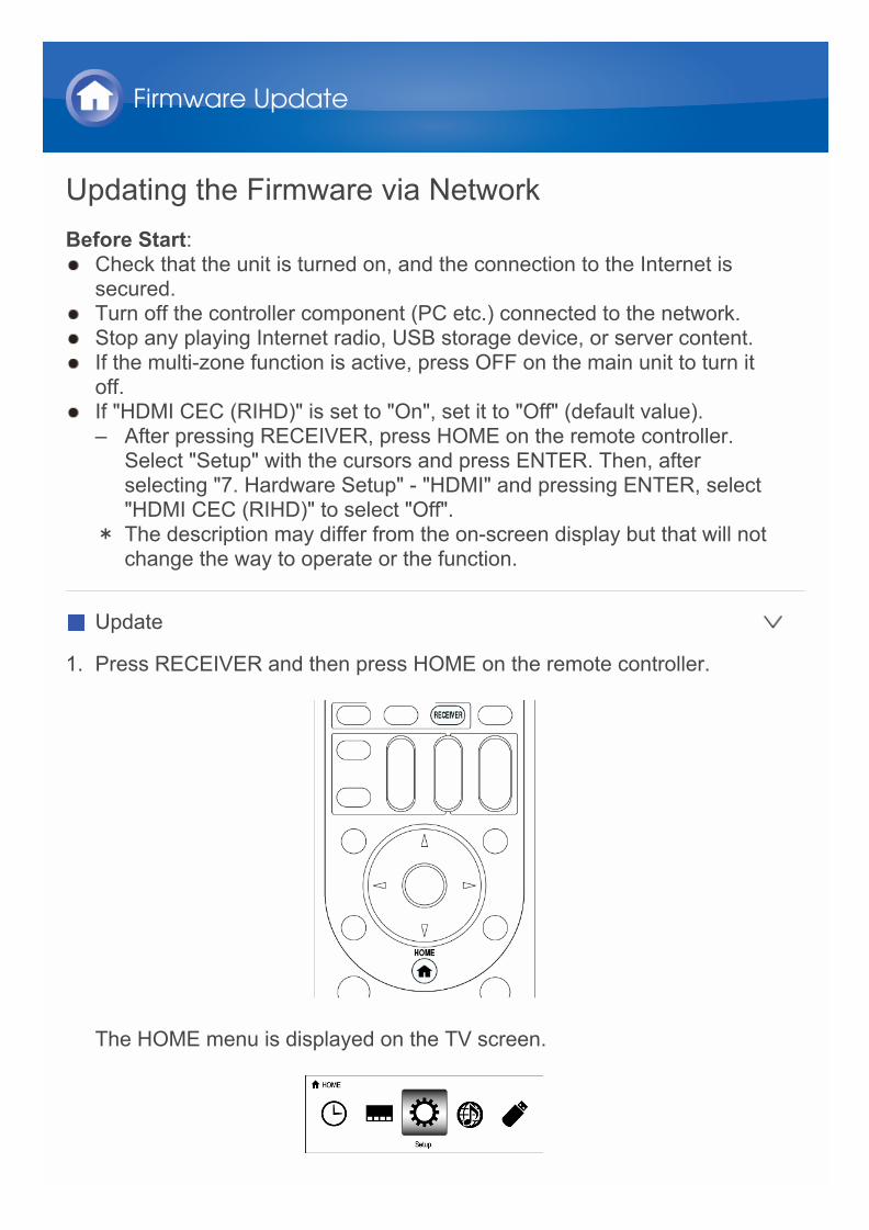
Updating the Firmware via NetworkBefore Start: Check that the unit is turned on, and the connection to the Internet is
secured. Turn off the controller component (PC etc.) connected to the network. Stop any playing Internet radio, USB storage device, or server content. If the multi-zone function is active, press OFF on the main unit to turn it
off. If "HDMI CEC (RIHD)" is set to "On", set it to "Off" (default value).
– After pressing RECEIVER, press HOME on the remote controller.Select "Setup" with the cursors and press ENTER. Then, afterselecting "7. Hardware Setup" - "HDMI" and pressing ENTER, select"HDMI CEC (RIHD)" to select "Off".
* The description may differ from the on-screen display but that will notchange the way to operate or the function.
Update
1. Press RECEIVER and then press HOME on the remote controller.
The HOME menu is displayed on the TV screen.
Firmware Update
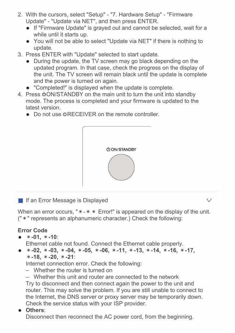
2. With the cursors, select "Setup" - "7. Hardware Setup" - "FirmwareUpdate" - "Update via NET", and then press ENTER. If "Firmware Update" is grayed out and cannot be selected, wait for a
while until it starts up. You will not be able to select "Update via NET" if there is nothing to
update.3. Press ENTER with "Update" selected to start update.
During the update, the TV screen may go black depending on theupdated program. In that case, check the progress on the display ofthe unit. The TV screen will remain black until the update is completeand the power is turned on again.
"Completed!" is displayed when the update is complete.4. Press ON/STANDBY on the main unit to turn the unit into standby
mode. The process is completed and your firmware is updated to thelatest version. Do not use RECEIVER on the remote controller.
If an Error Message is Displayed
When an error occurs, "*-** Error!" is appeared on the display of the unit.("*" represents an alphanumeric character.) Check the following:
Error Code *-01, *-10:
Ethernet cable not found. Connect the Ethernet cable properly. *-02, *-03, *-04, *-05, *-06, *-11, *-13, *-14, *-16, *-17,
*-18, *-20, *-21:Internet connection error. Check the following:– Whether the router is turned on– Whether this unit and router are connected to the networkTry to disconnect and then connect again the power to the unit androuter. This may solve the problem. If you are still unable to connect tothe Internet, the DNS server or proxy server may be temporarily down.Check the service status with your ISP provider.
Others:Disconnect then reconnect the AC power cord, from the beginning.

Updating the Firmware via USBBefore Start: Prepare a 64 MB or larger USB storage device.
– Media inserted in a USB card reader may not be used for this function.– USB storage devices with security function are not supported.– USB hubs and USB devices with hub function are not supported. Do
not connect these devices to the unit. Delete any data stored on the USB storage device. Turn off the controller component (PC etc.) connected to the network. Stop any playing Internet radio, USB storage device, or server content. If the multi-zone function is active, press OFF on the main unit to turn it
off. If "HDMI CEC (RIHD)" is set to "On", set it to "Off" (default value).
– After pressing RECEIVER, press HOME on the remote controller.Select "Setup" with the cursors and press ENTER. Then, afterselecting "7. Hardware Setup" - "HDMI" and pressing ENTER, select"HDMI CEC (RIHD)" to select "Off".
* Some USB storage devices may take long to load, may not be loadedcorrectly, or may not be correctly fed depending on the device or theircontent.
* Onkyo will not be liable whatsoever for any loss or damage of data, orstorage failure arising from the use of the USB storage device with thisAV receiver. Thank you for your understanding.
* The description may differ from the on-screen display but that will notchange the way to operate or the function.
Update
1. Connect the USB storage device to your PC.2. Download the firmware file from the Onkyo website to your PC and unzip.
Firmware files are named in the following way:ONKAVR****_************.zipUnzip the file on your PC. The number of unzipped files and foldersvaries depending on the model.
3. Copy all unzipped files and folders to the root folder of the USB storagedevice. Make sure to copy the unzipped files.
4. Press USB on the remote controller to select "USB".
Firmware Update

5. Connect the USB storage device to the USB port of the main unit. If you connect a USB hard disk drive to the USB port of the unit, we
recommend that you use its AC adapter to power it. If the USB storage device has been partitioned, each section will be
treated as an independent device.
6. After pressing RECEIVER, press HOME on the remote controller.
The HOME menu is displayed on the TV screen.
7. With the cursors, select "Setup" - "7. Hardware Setup" - "FirmwareUpdate" - "Update via USB", and then press ENTER. If "Firmware Update" is grayed out and cannot be selected, wait for a
while until it starts up. You will not be able to select "Update via USB" if there is nothing to
update.

8. Press ENTER with "Update" selected to start update. During the update, the TV screen may go black depending on the
updated program. In that case, check the progress on the display ofthe unit. The TV screen will remain black until the update is completeand the power is turned on again.
During the update, do not turn off, or disconnect then reconnect theUSB storage device.
"Completed!" is displayed when the update is complete.9. Disconnect the USB storage device from the unit.10.Press ON/STANDBY on the main unit to turn the unit into standby
mode. The process is completed and your firmware is updated to thelatest version. Do not use RECEIVER on the remote controller.
If an Error Message is Displayed
When an error occurs, "*-** Error!" is appeared on the display of the unit.("*" represents an alphanumeric character.) Check the following:
Error Code *-01, *-10:
USB storage device not found. Check whether the USB storage device orUSB cable is correctly inserted to the USB port of the main unit.Connect the USB storage device to an external power source if it has itsown power supply.
*-05, *-13, *-20, *-21:The firmware file is not present in the root folder of the USB storagedevice, or the firmware file is for another model. Retry from the downloadof the firmware file.
Others:Disconnect then reconnect the AC power cord, from the beginning.

Before starting the procedureProblems may be solved by simply turning the power on/off ordisconnecting/connecting the power cord, which is easier than working onthe connection, setting and operating procedure. Try the simple measureson both the unit and the connected device. If the problem is that the video oraudio is not output or the HDMI linked operation does not work,disconnecting/connecting the HDMI cable may solve it. When reconnecting,be careful not to wind the HDMI cable since if wound the HDMI cable maynot fit well. After reconnecting, turn off and on the unit and the connecteddevice.
Troubleshooting
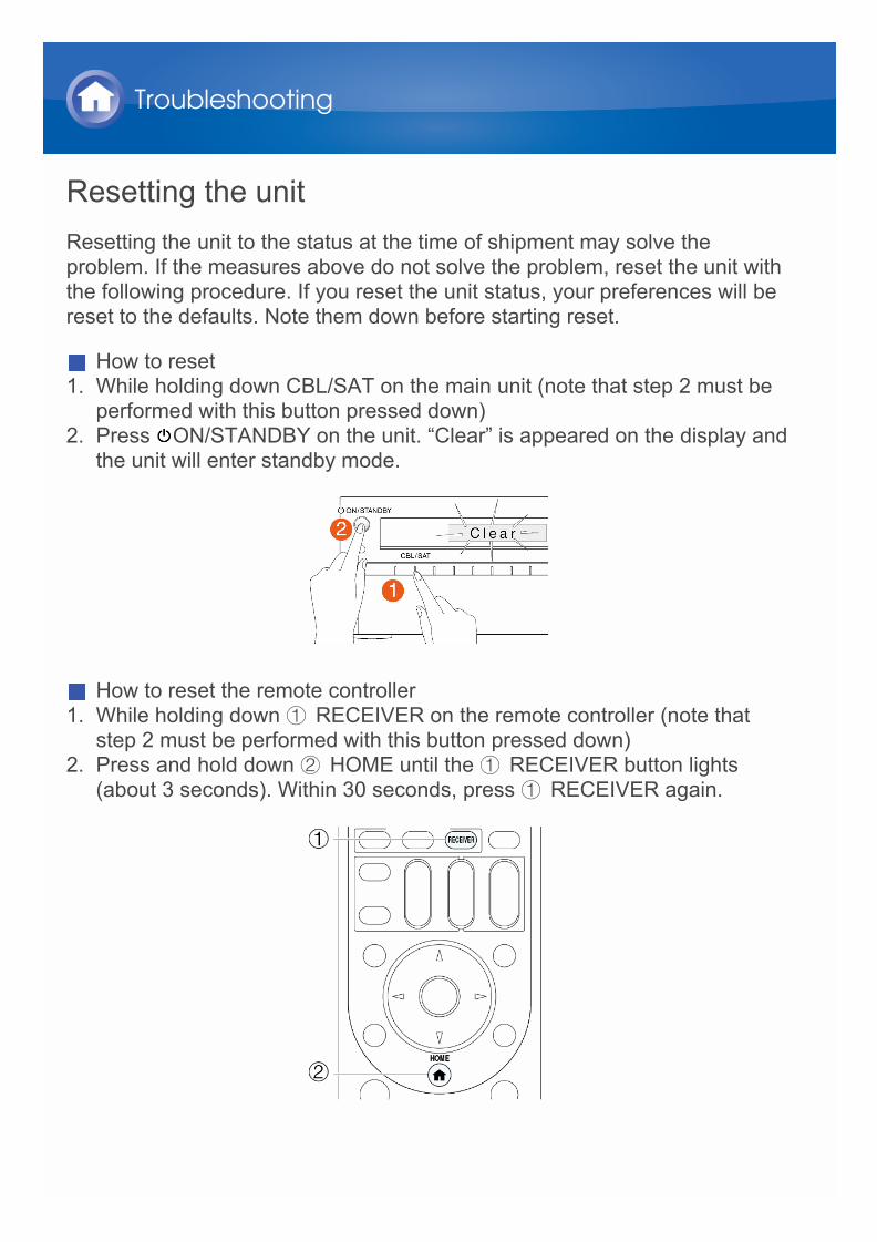
Resetting the unitResetting the unit to the status at the time of shipment may solve theproblem. If the measures above do not solve the problem, reset the unit withthe following procedure. If you reset the unit status, your preferences will bereset to the defaults. Note them down before starting reset.
How to reset1. While holding down CBL/SAT on the main unit (note that step 2 must be
performed with this button pressed down)2. Press ON/STANDBY on the unit. “Clear” is appeared on the display and
the unit will enter standby mode.
How to reset the remote controller1. While holding down 1 RECEIVER on the remote controller (note that
step 2 must be performed with this button pressed down)2. Press and hold down 2 HOME until the 1 RECEIVER button lights
(about 3 seconds). Within 30 seconds, press 1 RECEIVER again.
Troubleshooting
PowerCannot turn on the unit
Make sure that the power cord is properly plugged into the wall outlet. Unplug the power cord from the wall outlet, wait 5 seconds or more, then
plug it in again.
The unit turns off unexpectedly The unit will automatically enter standby mode when Auto Standby has
been set and launches.
The unit turns off and after restoring the power, it turns off again. The protection circuit has been activated. Remove the power cord from
the wall outlet immediately. Make sure that all speaker cables and inputsources are properly connected, and leave the unit with its power corddisconnected for 1 hour. After that, reconnect the power cord and turn thepower on. If the unit turns off again, avoid resetting it and unplug thepower cord. Then contact your Onkyo dealer.
Caution: If “CHECK SP WIRE” appears on the display, the speaker cablesmay be short-circuited.
WARNING: If smoke, smell or abnormal noise is produced by the unit,unplug the power cord from the wall outlet immediately and contact thedealer or Onkyo Support.
Troubleshooting
AudioThere is no sound, or it is very quiet
Make sure that the proper input source is selected. Make sure that connecting plugs are pushed in all the way. Make sure that the inputs and outputs of all components are connected
properly. Make sure that the polarity +/– of the speaker cables is correct, and that
no bare wires are in contact with the metal part of speaker terminals. Make sure that the input source is properly selected. Make sure that the speaker cables are not shorting. Check the volume. The volume level is adjustable between Min, 1 to 99,
Max (100). It is normal that the unit volume level is set up to 60 or around. If the MUTING indicator on the display flashes, press MUTING on the
remote controller to unmute the unit. While headphones are connected to the PHONES jack, no sound is
output from the speakers. If there is no sound from a BD/DVD player connected to an HDMI IN,
check the BD/DVD player’s output settings, and be sure to select asupported audio format.
Check the digital audio output setting on the connected component. Onsome game consoles, such as those that support DVD, the default settingis off.
With some DVD-Video discs, you need to select an audio output formatfrom a menu.
If your turntable uses an MC cartridge, you must connect an MC headamp, or an MC transformer.
Make sure that none of the connecting cables are bent, twisted, ordamaged.
Not all listening modes use all speakers. Perform the automatic speaker setup again or manually set the presence
or absence, crossover frequency, distance and level of each speaker. Make sure that the speaker setup microphone is not still connected. Set to "Off" if "Audio Selector" - "Fixed Mode" is set to "PCM" or "DTS".
Only the front speakers produce sound When the Stereo or Mono listening mode is selected, only the front
speakers and subwoofer produce sound. Make sure the speakers are configured correctly.
Only the center speaker produces sound
Troubleshooting

If you use the Dolby Surround listening mode with a mono source, suchas an AM radio station or mono TV program, the sound is concentrated inthe center speaker.
Make sure the speakers are configured correctly.
The surround speakers produce no sound When the T-D (Theater-Dimensional), Stereo or Mono listening mode is
selected, the surround speakers produce no sound. Depending on the source and current listening mode, not much sound
may be produced by the surround speakers. Try selecting anotherlistening mode.
Make sure the speakers are configured correctly.
The center speaker produces no sound When the Stereo or Mono listening mode is selected, the center speaker
produces no sound. Make sure the speakers are configured correctly.
There is no sound from surround back speakers, height speakers or frontwide speaker.
Depending on the source or current listening mode, not much sound maybe output from speakers. Try selecting another listening mode.
Make sure the settings for the speakers are made correctly.
The subwoofer produces no sound When you play source material that contains no information in the LFE
channel, the subwoofer produces no sound. Make sure the speakers are configured correctly.
There is no sound with a certain signal format When listening to Dolby Digital and/or DTS sound, digital connection is
necessary. Check the digital input terminal setting. If the connection is different from
the default, re-setting is necessary. Check the digital audio output setting on the connected component. On
some game consoles, such as those that support DVD, the default settingis OFF.
There is no sound with Dolby Atmos signal format Make sure the surround back speakers, the height speakers or wide
speakers are connected and configured as connected in the "SpeakerConfiguration".
Make sure the input signal is the Dolby Atmos format.
Cannot select the Pure Audio listening mode The Pure Audio listening mode cannot be selected while Zone 2/Zone 3
is on.
Cannot select a desired listening mode Depending on the connecting status of the speaker, some listening
modes may not be selected. Check the details in "Using the ListeningModes" section.
The speaker volume cannot be set as required Check to see if a maximum volume has been set.
Noise can be heard Using cable ties to bundle analog audio (RCA) cables with power cords,
speaker cables, etc. may degrade the audio performance, so refrain fromdoing it.
An analog audio (RCA) cable may be picking up interference. Tryrepositioning your cables.
The Late Night function does not work Make sure the source material is Dolby Digital, Dolby Digital Plus, or
Dolby TrueHD.
About DTS signals When DTS program material ends and the DTS bitstream stops, the unit
remains in DTS listening mode and the dts indicator remains on. This isto prevent noise when you use the pause, fast forward, or fast reversefunction on your player. If you switch your player from DTS to PCM, youmay not hear any sound because the unit does not switch formatsimmediately. In such case, you should stop your player for about 3seconds and then resume playback.
With some CD and LD players, you will not be able to playback DTSmaterial properly even though your player is connected to a digital inputon the unit. This is usually because the DTS bitstream has beenprocessed (e.g., output level, sampling rate, or frequency responsechanged) and the unit does not recognize it as a genuine DTS signal. Insuch cases, you may hear noise.
Playing DTS program material, using the pause, fast forward, or fastreverse function on your player may produce a short audible noise. Thisis not a malfunction.
The beginning of audio received by an HDMI IN cannot be heard Since it takes longer to identify the format of an HDMI signal than it does
for other digital audio signals, audio output may not start immediately.
VideoThere is no picture
Make sure that all video connecting plugs are pushed in all the way. Make sure that each video component is properly connected. If the TV is connected to the HDMI OUT jack of the unit, set
"1. Input/Output Assign" - "Monitor Out" - "Monitor Out" to "MAIN" or"SUB" according to the output jack. If the playback source is connected tothe video (composite) jack or component video jacks and you want tooutput the video to the TV via the HDMI OUT jack, set "HDMI Input" to "-----".
If the video source is connected to a component video input, you mustassign that input to an input selector, and your TV must be connected toCOMPONENT VIDEO OUT terminal.
If the video source is connected to a composite video input, your TV mustbe connected to the MONITOR OUT V terminal.
If the video source is connected to an HDMI input, you must assign thatinput to an input selector, and your TV must be connected to the HDMIoutput(s).
While the Pure Audio listening mode is selected, the analog videocircuitry is turned off and only video signals input through HDMI IN can beoutput.
Make sure the switching of input screens is proper at the monitor sidesuch as a TV.
When the image input from the composite video input terminal does notget displayed, make sure that the component video input terminal is notset to the selected input. If selected, images input from the compositevideo input terminal cannot be output to this input switching. If onlycomposite video input terminal connection is used, set the componentvideo input terminal to "----- ."
Images of a component connected to the composite video input terminalcannot be output by converting on the monitor of a TV or othercomponents connected to COMPONENT VIDEO OUT terminal.
If the input selector to which the input from the TV connected to the HDMIOUT SUB jack is connected is changed on this unit when "1. Input/OutputAssign" - "Monitor Out" - "Monitor Out" is set to "MAIN+SUB", or "MAIN"and when outputting to Zone 2, the video from the TV connected to HDMIOUT MAIN stops displaying.
"Resolution" is effective only for the HDMI OUT MAIN jack if"1. Input/Output Assign" - "Monitor Out" - "Monitor Out" is set to"MAIN+SUB".
Troubleshooting
There is no picture from a source connected to an HDMI IN Reliable operation with an HDMI-to-DVI adapter is not guaranteed. In
addition, video signals from a PC are not supported. Check if "Resolution Error" is displayed on the main unit display when
video input via HDMI IN jack is not displayed. In this case, the TV doesnot support the resolution of the video input from the player. Change thesetting on the player.
The on-screen menus do not appear On your TV, make sure that the video input to which this unit is connected
is selected. Set "On Screen Display" to "On" in "OSD Setup".

TunerReception is noisy, FM stereo reception is noisy, or the "FM STEREO"indicator does not stay lit
Re-check the antenna connection. Relocate your antenna. Move the unit away from your TV or PC. Passing cars and airplanes can cause interference. Concrete walls weaken radio signals. Listen to the station in mono. When listening to an AM station, operating the remote controller may
cause noise. If nothing improves the reception, install an outdoor antenna.
Troubleshooting

Remote ControllerThe remote controller does not work
Before operating this unit using remote controller, be sure to pressRECEIVER.
Make sure that the batteries are installed with the correct polarity. Install new batteries. Do not mix different types of batteries, or old and
new batteries. Make sure that the remote controller is not too far away from the unit, and
that there is no obstruction between the remote controller and the remotecontrol sensor of the unit.
Make sure that the unit is not subjected to direct sunshine or inverter-typefluorescent lights. Relocate if necessary.
If the unit is installed in a rack or cabinet with colored-glass doors or if thedoors are closed, the remote controller may not work reliably.
Make sure you have selected the correct remote controller mode. When using the remote controller to control other manufacturers’ AV
components, some buttons may not work as expected. Make sure you have entered the correct remote control code. Make sure to set the same ID on both the unit and remote controller.
Operating other Onkyo component by using a RI remote control code isnot available
Make sure that the Onkyo component is properly connected with RIcable. When RI cable is used for connection, make sure to connectanalog audio (RCA) cable as well. (Connecting only an RI cable will notbe enough.)
Make sure you have selected the correct remote controller mode. Make sure that the input display is correctly set. Input the RI remote control code again. When the RI remote control code is input, point the remote controller at
remote control sensor of the unit.
Cannot operate Onkyo components (ones without RI connection) andcomponents of other makers
Make sure that the connection with other components is correct. Input a correct remote control code again. If there are several codes, try
each code. Make sure that the remote controller mode is correctly selected. Operate the remote controller by setting toward the light receiving section
of each component.
Troubleshooting

Some components may not start the operation.
The remote controller cannot learn other component's remote control. Make sure the procedure of learning other component's remote control
has been performed correctly. Because of differences in transfer systems, some remote controller may
not function as intended and learning may not be successful.
RI Dock for iPod/iPhoneThere is no sound
Make sure your iPod/iPhone is actually playing. Make sure your iPod/iPhone is properly inserted in the Dock. Make sure the unit is turned on, the correct input source is selected, and
the volume is turned up. Make sure the plugs are pushed in all the way. Try resetting your iPod/iPhone.
There is no video Make sure that your iPod/iPhone model’s TV OUT setting is set to On. Make sure the correct input is selected on your TV or the unit. Some versions of the iPod/iPhone do not output video.
The AV receiver’s remote controller does not control my iPod/iPhone Make sure your iPod/iPhone is properly inserted in the Dock. If your
iPod/iPhone is in a case, it may not connect properly to the Dock. Alwaysremove your iPod/iPhone from the case before inserting it into the Dock.
The iPod/iPhone cannot be operated while it is displaying the Apple logo. Make sure you have selected the correct remote controller mode. When you use the AV receiver’s remote controller, point it toward this
unit. Before operating with the remote controller, you may need to play on your
iPod/iPhone to make the input selector be recognized. Try resetting your iPod/iPhone. Depending on your iPod/iPhone model and generation, some buttons
may not work as expected.
The unit unexpectedly selects my iPod/iPhone as the input source Always pause iPod/iPhone playback before selecting a different input
source. If playback is not paused, the Direct Change function may selectyour iPod/iPhone as the input source by mistake during the transitionbetween tracks.
iPod/iPhone does not work properly Try reconnecting your iPod/iPhone.
Troubleshooting
Multi-zone FunctionThere is no sound
When you connect a CD player or such other player without HDMI outputjack, connect it to the analog audio input jacks of the unit. Multi-zoneoutput is not possible if the connection is only with digital optical cable ordigital coaxial cable. In case of analog connection, analog audio outputsetting may be necessary on the player.
Troubleshooting
Wi-Fi (Wireless LAN) NetworkCannot access to Wi-Fi (Wireless LAN) network or sound playback isinterrupted and communication does not work
Try plugging/unplugging the power supply of wireless LAN router and theunit, check the wireless LAN router power-on status, and try reboot of thewireless LAN router.
The setting of SSID and encryption (WEP, etc.) is not correct. Make surethe network settings of the unit is properly set.
Connection to an SSID that includes multi-byte characters is notsupported. Name the SSID of the wireless LAN router using single-bytealphanumeric characters only and try again.
Cannot receive radio wave due to a bad connection. Shorten the distancefrom wireless LAN access point or remove obstacles for a good visibility,and try again. Place the unit away from microwave ovens or other accesspoints. 2.4 GHz band for wireless LAN may not be enough. ConnectETHERNET terminal of the unit and the router via an Ethernet cable afterselecting "7. Hardware Setup" - "Network" and changing "Wi-Fi" to"Off(Wired)".
Place the unit away from the components emitting electromagnetic waveson the 2.4 GHz band (microwave ovens, game consoles, etc.). If thisdoes not solve the problem, stop using other components which emitelectromagnetic waves.
When other wireless LAN devices are used near the unit, several issuessuch as interrupted playback and communication may occur. You canavoid these issues by changing the channel of your wireless LAN router.For instructions on changing channels, see the instruction manualprovided with your wireless LAN router.
If there is a metallic object near the unit, wireless LAN connection maynot be possible as the metal can effect on the radio wave.
If there is more than one access point in the network, separate eachaccess point.
It is recommended to place the Wi-Fi router (access point) and the unit inthe same room.
The connection does not complete even when the automatic settingbutton is pressed on the wireless LAN router
The wireless LAN router setting may be switched to Manual. Return thesetting to Auto.
Try the manual set-up. The connection may succeed.
Troubleshooting
On the list of SSID on the TV menu screen, there is no correspondingSSID
When the wireless LAN router setting is at stealth mode (mode to hidethe SSID key) or when ANY connection is off, the SSID is not displayed.Change the setting and try again.
BluetoothMusic playback is unavailable on the unit even after successful Bluetoothconnection
Depending on the characteristics or specifications of your Bluetooth-enabled device, playback on the unit is not guaranteed.
When the audio volume of your Bluetooth-enabled device is set low, theplayback of audio may be unavailable. Volume up the Bluetooth-enableddevice.
Depending on the Bluetooth-enabled device, Send/Receive selectorswitch may be provided. Select Send mode.
Even when a music file is playing on the Bluetooth-enabled device, thesound cannot be played if the connection is not established with the unit.Make sure that the unit is connected (this unit is selected as the soundoutput destination).
Sound is interrupted Problem may be occurring at the Bluetooth-enabled device. Check the
information on a web page.
The audio quality is poor after connection with a Bluetooth-enableddevice
The Bluetooth reception is poor. Move the Bluetooth-enabled devicecloser to the unit or remove any obstacle between the Bluetooth-enableddevice and this unit.
Cannot connect with this unit Try plugging/unplugging the power of the unit and try turning on/off the
Bluetooth-enabled device. Re-startup of the Bluetooth-enabled devicemay be effective.
The Bluetooth-enabled device does not support the profiles required forthis unit.
The Bluetooth function of the Bluetooth-enabled device is not enabled.Refer to the user manual of the Bluetooth-enabled device for how toenable the Bluetooth function.
Near components such as microwave oven or cordless phone, which usethe radio wave in the 2.4 GHz range, a radio wave interference mayoccur, which disables the use of this unit.
Bluetooth connection cannot be built When building a Bluetooth connection between this unit and your
Troubleshooting
Bluetooth-enabled device for the first time, if the connection fails, select"7. Hardware Setup" - " Bluetooth", execute "Clear" in "PairingInformation", turn off and then on again your Bluetooth-enabled device toclear the device name, and build the connection again.
If there is a metallic object near the unit, Bluetooth connection may not bepossible as the metal can effect on the radio wave.
If the wireless LAN and Bluetooth connections are used at the same time,try to connect the ETHERNET port and router with the Ethernet cableafter selecting “7. Hardware Setup” - "Network" and changing “Wi-Fi” to"Off(Wired)" for a better connection.
The Auto Reconnect function does not work This may not work with some Bluetooth-enabled devices. In that case,
pair the unit and the Bluetooth-enabled device and then play again.
NET/USB FunctionCannot access the network server
When NET is blinking, the AV receiver is not properly connected to thehome network.
Make sure your network server has been started up. Make sure your network server is properly connected to the home
network. Make sure your network server is correctly set. Make sure that the router LAN side port is properly connected to the AV
receiver. Make sure that the correct IP address is allocated in "7. Hardware Setup"
- "Network".
Playback stops while listening to music files on the network server Make sure the network server is compatible with this unit. When the PC is serving as the network server, try quitting any application
software other than the server software (Windows Media® Player 12 etc.). If the PC is downloading or copying large files, the playback may be
interrupted.
Cannot access the Internet radio Certain network service or contents available through the unit may not be
accessible in case the service provider terminates its service. If a specific radio station is unavailable for listening, make sure the
registered URL is correct, or whether the format distributed from the radiostation is supported by the AV receiver.
When NET is blinking, the AV receiver is not properly connected to thehome network.
Make sure that your modem and router are properly connected, andmake sure they are both turned on.
Make sure that connecting to Internet from other components is possible.If connecting is not possible, turn off all components connected to thenetwork, wait for a while, and then turn on the components again.
Make sure that the router LAN side port is properly connected to the AVreceiver.
Make sure that the correct IP address is allocated in "7. Hardware Setup"- "Network".
Depending on ISP, setting the proxy server is necessary. Make sure that the used router and/or modem is supported by your ISP.
Troubleshooting
Cannot connect to the AV receiver from a Web browser Make sure that the IP address of the AV receiver is correctly input to the
Internet browser. When DHCP is used for allocating the IP address, the IP address of this
AV receiver may have been changed. Make sure that both AV receiver and PC are properly connected to the
network.
USB storage device is not displayed Make sure that USB storage device and USB cable are securely plugged
to the USB port of this AV receiver. Remove the USB storage device from the AV receiver once, and then try
re-connecting. Performance of the hard disk that receives power from the USB port of
the unit is not guaranteed. Depending on the type of format, the playback may not be performed
normally. Check the type of the file formats that is supported. USB storage device with security functions may not be played.

OthersPower consumption in standby mode
In the following cases, the power consumption in standby mode mayreach up to a maximum of 5 W:– When “Network Standby” in "7. Hardware Setup" - "Network" is set to
"On".– When “HDMI CEC (RIHD)” is set to “On”. (Depending on the TV
status, the AV receiver will enter normal standby mode.)– The “HDMI Through” setting is set to other than “Off”.– When “Wakeup via Bluetooth” in "7. Hardware Setup" - "Bluetooth" is
set to "On". The power consumption in standby mode may be larger than the value
above while the MHL (Mobile High-definition Link) enabled mobile deviceconnected to the AUX INPUT HDMI/MHL jack is being charged.
The sound changes when I connect my headphones When a listening mode other than Direct, Pure Audio, or Mono is
selected, connecting a headphone automatically selects Stereo.
The display does not work The display is turned off when the Pure Audio listening mode is selected.
How do I change the language of a multiplex source Select “Main” or “Sub” for “Multiplex Input Channel” in “3. Audio Adjust” -
"Multiplex/Mono".
The RI functions do not work To use RI, you must make an RI connection and an analog audio (RCA)
connection between the component and AV receiver, even if they areconnected digitally.
While Zone 2/Zone 3 is selected, the RI functions do not work.
The functions System On/Auto Power On and Direct Change do not workfor components connected via RI
These functions do not work when Zone 2/Zone 3 is turned on.
When performing Automatic Speaker Setup, the measurement fails andthe message “Ambient noise is too high.” is displayed.
This can be caused by a malfunction in your speaker unit. Check if theunit produces normal sounds.
Troubleshooting
The display is dark Make sure that Dimmer function is not working. Press DIMMER button
and change the brightness level of the display.
The following settings can be made for the component video andcomposite video inputs.
While holding down the input selector button to configure, press HOMEonce at a time until “Video ATT:On” appears on the display. To resumethe setup, repeat the above described step until “Video ATT:Off” appearson the display.This setting is possible for input selectors assigned with one of the videoinputs "VIDEO 1" to "VIDEO 3" in "1.Input/Output Assign" - "ComponentVideo Input" or "Composite Video Input". If you have a game consoleconnected to the composite video input, and the picture is not very clear,you can attenuate the gain. Video ATT: Off: (Default). Video ATT: On: (Gain is reduced by 2dB.)
The picture on your TV/monitor connected to the HDMI output(s) isunstable
Try turning the DeepColor function off.To turn off the DeepColor function, press STB/DVR and ON/STANDBYon the AV receiver simultaneously.While holding down STB/DVR, press ON/STANDBY repeatedly until“Deep Color:Off” is appeared on the display. To reactivate the DeepColorfunction, repeat the above described step until “Deep Color:On” appearson the display.
The AV receiver contains a microPC for signal processing and controlfunctions. In very rare situations, severe interference, noise from an externalsource, or static electricity may cause it to lockup. In the unlikely event thatthis happens, unplug the power cord from the wall outlet, wait at least 5seconds, and then plug it back in.
Onkyo is not responsible for damages (such as CD rental fees) due tounsuccessful recordings caused by the unit’s malfunction.Before you record important data, make sure that the material will berecorded correctly.
Before disconnecting the power cord from the wall outlet, set the AV receiverto standby.
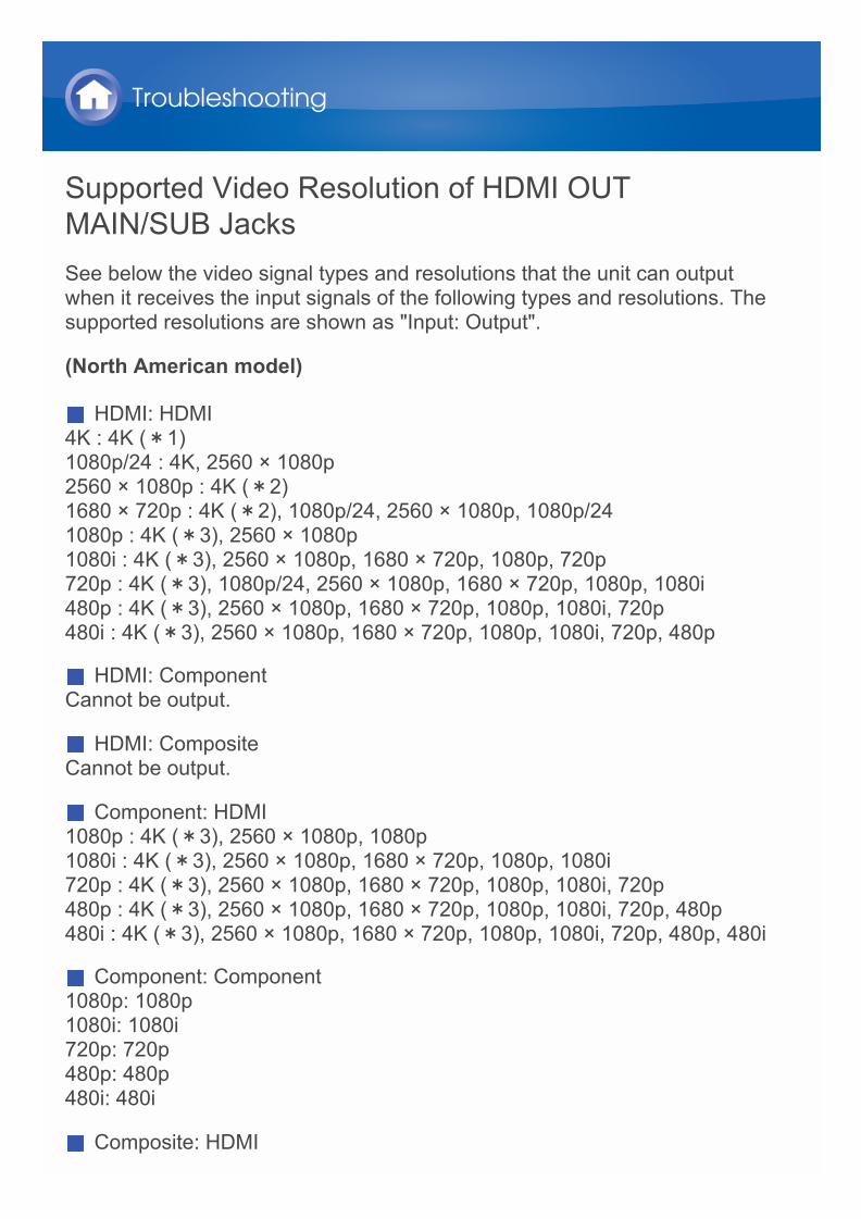
Supported Video Resolution of HDMI OUTMAIN/SUB JacksSee below the video signal types and resolutions that the unit can outputwhen it receives the input signals of the following types and resolutions. Thesupported resolutions are shown as "Input: Output".
(North American model)
HDMI: HDMI4K : 4K (*1)1080p/24 : 4K, 2560 × 1080p2560 × 1080p : 4K (*2)1680 × 720p : 4K (*2), 1080p/24, 2560 × 1080p, 1080p/241080p : 4K (*3), 2560 × 1080p1080i : 4K (*3), 2560 × 1080p, 1680 × 720p, 1080p, 720p720p : 4K (*3), 1080p/24, 2560 × 1080p, 1680 × 720p, 1080p, 1080i480p : 4K (*3), 2560 × 1080p, 1680 × 720p, 1080p, 1080i, 720p480i : 4K (*3), 2560 × 1080p, 1680 × 720p, 1080p, 1080i, 720p, 480p
HDMI: ComponentCannot be output.
HDMI: CompositeCannot be output.
Component: HDMI1080p : 4K (*3), 2560 × 1080p, 1080p1080i : 4K (*3), 2560 × 1080p, 1680 × 720p, 1080p, 1080i720p : 4K (*3), 2560 × 1080p, 1680 × 720p, 1080p, 1080i, 720p480p : 4K (*3), 2560 × 1080p, 1680 × 720p, 1080p, 1080i, 720p, 480p480i : 4K (*3), 2560 × 1080p, 1680 × 720p, 1080p, 1080i, 720p, 480p, 480i
Component: Component1080p: 1080p1080i: 1080i720p: 720p480p: 480p480i: 480i
Composite: HDMI
Troubleshooting
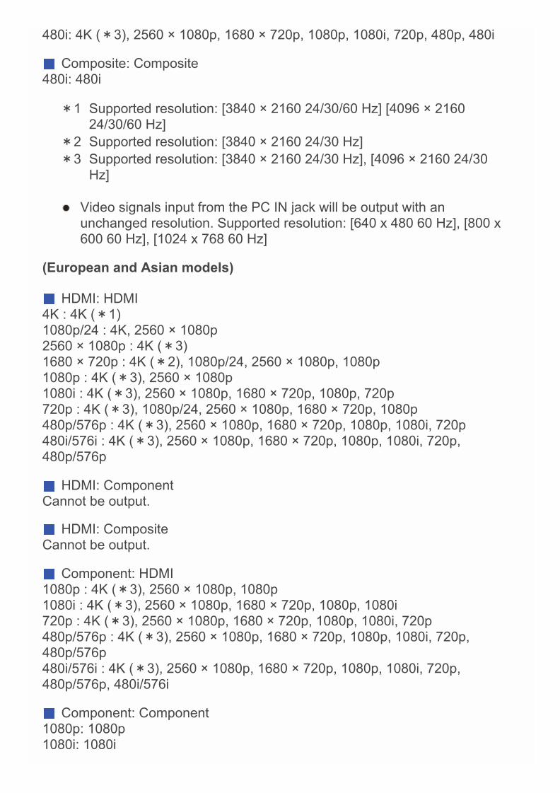
480i: 4K (*3), 2560 × 1080p, 1680 × 720p, 1080p, 1080i, 720p, 480p, 480i
Composite: Composite480i: 480i
*1 Supported resolution: [3840 × 2160 24/30/60 Hz] [4096 × 216024/30/60 Hz]
*2 Supported resolution: [3840 × 2160 24/30 Hz]*3 Supported resolution: [3840 × 2160 24/30 Hz], [4096 × 2160 24/30
Hz]
Video signals input from the PC IN jack will be output with anunchanged resolution. Supported resolution: [640 x 480 60 Hz], [800 x600 60 Hz], [1024 x 768 60 Hz]
(European and Asian models)
HDMI: HDMI4K : 4K (*1)1080p/24 : 4K, 2560 × 1080p2560 × 1080p : 4K (*3)1680 × 720p : 4K (*2), 1080p/24, 2560 × 1080p, 1080p1080p : 4K (*3), 2560 × 1080p1080i : 4K (*3), 2560 × 1080p, 1680 × 720p, 1080p, 720p720p : 4K (*3), 1080p/24, 2560 × 1080p, 1680 × 720p, 1080p480p/576p : 4K (*3), 2560 × 1080p, 1680 × 720p, 1080p, 1080i, 720p480i/576i : 4K (*3), 2560 × 1080p, 1680 × 720p, 1080p, 1080i, 720p,480p/576p
HDMI: ComponentCannot be output.
HDMI: CompositeCannot be output.
Component: HDMI1080p : 4K (*3), 2560 × 1080p, 1080p1080i : 4K (*3), 2560 × 1080p, 1680 × 720p, 1080p, 1080i720p : 4K (*3), 2560 × 1080p, 1680 × 720p, 1080p, 1080i, 720p480p/576p : 4K (*3), 2560 × 1080p, 1680 × 720p, 1080p, 1080i, 720p,480p/576p480i/576i : 4K (*3), 2560 × 1080p, 1680 × 720p, 1080p, 1080i, 720p,480p/576p, 480i/576i
Component: Component1080p: 1080p1080i: 1080i
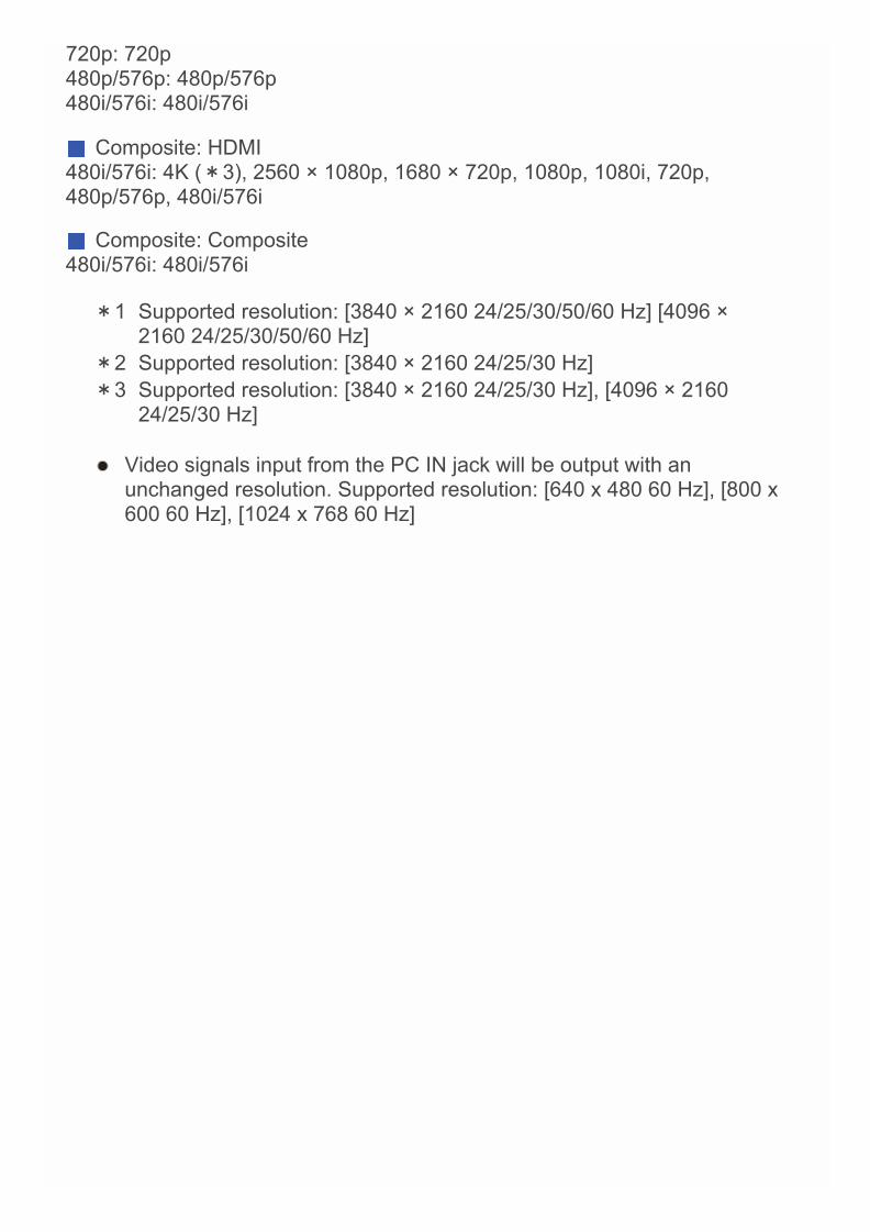
720p: 720p480p/576p: 480p/576p480i/576i: 480i/576i
Composite: HDMI480i/576i: 4K (*3), 2560 × 1080p, 1680 × 720p, 1080p, 1080i, 720p,480p/576p, 480i/576i
Composite: Composite480i/576i: 480i/576i
*1 Supported resolution: [3840 × 2160 24/25/30/50/60 Hz] [4096 ×2160 24/25/30/50/60 Hz]
*2 Supported resolution: [3840 × 2160 24/25/30 Hz]*3 Supported resolution: [3840 × 2160 24/25/30 Hz], [4096 × 2160
24/25/30 Hz]
Video signals input from the PC IN jack will be output with anunchanged resolution. Supported resolution: [640 x 480 60 Hz], [800 x600 60 Hz], [1024 x 768 60 Hz]
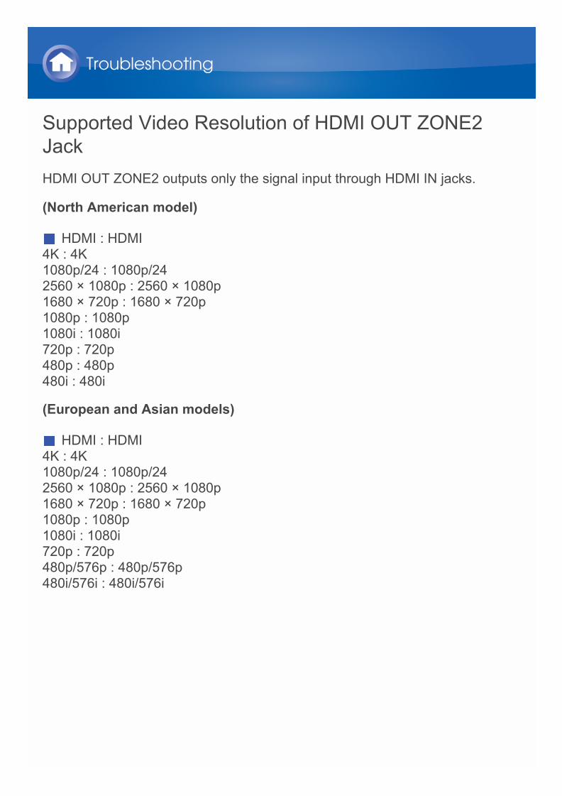
Supported Video Resolution of HDMI OUT ZONE2JackHDMI OUT ZONE2 outputs only the signal input through HDMI IN jacks.
(North American model)
HDMI : HDMI4K : 4K1080p/24 : 1080p/242560 × 1080p : 2560 × 1080p1680 × 720p : 1680 × 720p1080p : 1080p1080i : 1080i720p : 720p480p : 480p480i : 480i
(European and Asian models)
HDMI : HDMI4K : 4K1080p/24 : 1080p/242560 × 1080p : 2560 × 1080p1680 × 720p : 1680 × 720p1080p : 1080p1080i : 1080i720p : 720p480p/576p : 480p/576p480i/576i : 480i/576i
Troubleshooting
Linked Operation with CEC-compatible ComponentsThe AV receiver is compatible with the following components (as of January2014).
TV (Random order): Toshiba TV sets Sharp TV sets
Players/Recorders (Random order): Onkyo and Integra RIHD-compatible players Toshiba players and recorders Sharp players and recorders (only when used together with Sharp TV
sets)
Models other than those mentioned above may have some interoperability ifcompatible with CEC, which is part of the HDMI Standard, but operationcannot be guaranteed.
Note: For RI functions to work properly, do not connect more RIHD-compatible components than the quantities specified below, to the HDMIjack. RI functions are not guaranteed when more RIHD-compatiblecomponents than the below mentioned quantities are connected.Furthermore, do not connect the AV receiver to another AV receiver/AVamplifier via HDMI. Blu-ray Disc/DVD players: up to 3. Blu-ray Disc/DVD recorders: up to 3. Cable TV tuner, terrestrial digital tuner, and satellite broadcasting tuner:
up to 4 units.
Reference Information
Checking whether the HDMI Linked OperationSettings Are Enabled1. Turn on the power of all connected components.2. Turn off the power of the TV, and confirm that the power of the connected
components is turned off automatically with the link operation.3. Turn on the power of the Blu-ray Disc/DVD player/recorder.4. Start playback on the Blu-ray Disc/DVD player/recorder, and verify the
following: The AV receiver automatically turns on, and selects the input to which
the Blu-ray Disc/DVD player/recorder is connected. The TV automatically turns on, and selects the input to which the AV
receiver is connected.5. Following the operating instructions of the TV, select “Use the TV
speakers” from the menu screen of the TV, and confirm that the audio isoutput from the speakers of the TV, and not from the speakers connectedto the AV receiver.
6. Select “Use the speakers connected from the AV receiver” from the menuscreen of the TV, and confirm that the audio is output from the speakersconnected to the AV receiver, and not from the TV speakers.
Note: Even if you set to output audio on the TV speakers, audio will be output
from the speakers connected to the AV receiver when you adjust thevolume or switch the input on the AV receiver. To output audio from theTV speakers, redo the corresponding operations on the TV.
In case of an RIHD connection with RI and RI audio control compatiblecomponents, do not connect the RI cable at the same time.
On the TV, when you select anything other than the HDMI jack to whichthe AV receiver is connected, the input on the AV receiver will beswitched to “TV/CD”.
The AV receiver will automatically power on in conjunction when itdetermines it to be necessary. Even if the AV receiver is connected to anRIHD compatible TV or player/recorder, it will not power on if it is notnecessary. It may not power on in conjunction when the TV is set tooutput audio from the TV.
Linked system functions with the AV receiver may not work depending onthe component model connected. In such cases, operate the AV receiverdirectly.
When the player/recorder cannot be operated with the remote controller
Reference Information

of the AV receiver, the corresponding component may not beprogrammed to support the remote controller operation of CEC. Programthe remote control code of the component maker to the remote controllerfor using.
About HDMIHDMI (High-Definition Multimedia Interface) is a digital interface standard forconnecting TVs, projectors, Blu-ray Disc/DVD players, set-top boxes, andother video components. Until now, several separate video and audio cableshave been required to connect AV components. With HDMI, a single cablecan carry control signals and digital audio of digital video (2-channel PCM,multichannel digital audio, and multichannel PCM).The HDMI video stream (i.e., video signal) is compatible with DVI (DigitalVisual Interface) (*1), so TVs and displays with a DVI input can beconnected by using an HDMI-to-DVI adapter cable. (This may not work withsome TVs and displays, resulting in no picture.)This unit supports HDCP (High-bandwidth Digital Content Protection) (*2),so it can display picture only on HDCP-compatible components.HDMI of the unit supports the following functions.Audio Return Channel, 3D, x.v.Color, DeepColor, Lip Sync, 4K (Upscalingand Passthrough).
Audio Formats Supported by The Unit: 2-channel linear PCM (32 - 192 kHz, 16/20/24 bit) Multichannel linear PCM (up to 7.1 ch, 32 - 192 kHz, 16/20/24 bit) Bitstream (Dolby Atmos, Dolby Digital, Dolby Digital Plus, Dolby TrueHD,
DTS, DTS-HD High Resolution Audio, DTS-HD Master Audio) DSDYour Blu-ray Disc/DVD player must also support HDMI output of the aboveaudio formats.
About Copyright Protection:The unit supports Revision 1.4 and Revision 2.2 (HDMI OUT MAIN andHDMI IN3 only) of the HDCP (High-bandwidth Digital Content Protection) (*2), a copy-protection system for digital video signals. Other devicesconnected to the unit must also support HDCP.
*1 DVI (Digital Visual Interface): The digital display interface standardset by the DDWG (*3) in 1999.
*2 HDCP (High-bandwidth Digital Content Protection): The videoencryption technology developed by Intel for HDMI/DVI. It isdesigned to protect video content and requires a HDCP-compatibleHDMI/DVI receiver to display the encrypted video.
*3 DDWG (Digital Display Working Group): Lead by Intel, Compaq,Fujitsu, Hewlett-Packard, and Silicon Image, this open industry
Reference Information

group’s objective is to address the industry’s requirements for adigital connectivity specification for high-performance PC and digitaldisplays.
Note: There are some content that can be played only with HDCP Rev. 2.2
compatible devices. To play such content, connect an HDCP Rev.2.2compatible TV or player to the HDMI OUT MAIN jack or HDMI IN3 jack ofthe unit.
The HDMI video stream (i.e., video signal) is compatible with DVI (DigitalVisual Interface), so TVs and displays with a DVI input can be connectedby using an HDMI-to-DVI adapter cable. (Note that DVI connections onlycarry video, so you will need to make a separate connection for audio.)However, reliable operation with such an adapter is not guaranteed. Inaddition, video signals from a PC are not supported.
The HDMI audio signal (sampling rate, bit length, etc.) may be restrictedby the connected source component. If the picture is poor or there is nosound from a component connected via HDMI, check its setup. Refer tothe connected component’s instruction manual for details.
Home network (LAN)The connection of several components via cables enabling the mutualcommunication is called a network.At households, many families create (generally, the term "build" is used) anetwork to connect PC and gaming machines to the Internet and toexchange data between PC.The network established in a relatively narrow area such as one householdis called a LAN (Local Area Network).In this manual, a term "home network" (network for a family) is used insteadof "LAN," so this LAN becomes more familiar.By connecting this unit with the network server such as a PC, playing musicfiles in the network server (in the PC) is possible. Moreover, by connecting tothe Internet, listening to the Internet radio is also possible.This unit, PC, and Internet are not directly connected.When connecting with a PC and/or Internet, several components (networkcomponents) are necessary.
Components necessary for establishing a home network (LAN):Components necessary for the home network (LAN) for using the NETfunction of this unit are as follows.
RouterA router is a device that controls information (data) flow between the unit,PC, and the Internet.As a network term, the flow of information (data) is called "traffic". The routerhas a role to control the information flow as the traffic control, betweenconnected components. A router with a built-in 100Base-TX switch is recommended. In addition, if your router has the DHCP function, facilitating the network
setting becomes possible. Some routers have a built-in modem, and some Internet Service
Providers (ISP) require you to use specific routers.Please consult your ISP or PC dealer if you are unsure.
CAT-5 Ethernet cableThe Ethernet cable is a cable that actually connects components thatcomprise the network. There are straight type and cross type Ethernetcables. Use a shielded CAT-5 Ethernet cable (straight-type) to connect the unit to
your home network.
Reference Information

Consult your cable store for details of Ethernet cable.
Network server (When PC etc./network server is used)Component that stores music files and provides those files at the time ofplayback. Requirements for use with this unit depend on the component that is used
as a network server. Conditions for pleasant playback of music files on the unit depend on the
using network server (PC performance). See instruction manuals of usingcomponents.
Modem (when Internet radio is used)Device that connects home network (LAN) and InternetThere are many kinds of modems depending on the forms of Internetconnection.In addition, when connecting to the Internet, it is required to conclude anagreement with a company that provides Internet connection service, calledISP (Internet Service Provider).Use a modem that is recommended by your ISP company for the Internetconnection.There are some devices that have both router and modem functions.Within above network components, prepare a router, Ethernet cable, andnetwork server when the NET function "network server" is used.For enjoying the NET function "Internet radio," it is necessary to use therouter, Ethernet cable, and modem (and agreement with ISP).
Server RequirementsServer playback
This unit can play digital music files stored on a PC or media server andsupports the following technologies: Windows Media® Player 11 Windows Media® Player 12 DLNA-certified media serverThe network server must be connected to the same network as this unit.Up to 20,000 folders can be displayed, and folders may be nested up to 16levels deep.
Note: Depending on the media server, the unit may not recognize it, or maynot be able to play its music files.
Remote playbackRemote playback is the function that enables this unit to play music filessaved in different components by operating the DLNA-compliant controllercomponent and PC in the home network. Windows Media® Player 12 DLNA-certified (within DLNA Interoperability Guidelines version 1.5)
media server or controller component.* The setting varies depending on the media server or controller
components. Refer to your components’ instruction manual for details.If the operating system of your personal PC is Windows® 8/Windows® 7,Windows Media® Player 12 is already installed. For more information, seethe Microsoft web site.
Reference Information

USB Storage Device Requirements USB Mass Storage Class (but not always guaranteed). FAT16 or FAT32 file system format. If the USB storage device has been partitioned, each section will be
treated as an independent device. Up to 20,000 folders can be displayed, and folders may be nested up to
16 levels deep. USB hubs and USB storage devices with hub functions are not
supported. Do not connect these devices to the unit.
Note: If the media you connect is not supported, the message “No Storage” will
be displayed. Sound files that are protected by copyright cannot be played. When the USB audio player and this unit are connected, the audio player
screen and the screen of the unit may be different. In addition, controlfunctions of the audio player (classifying and sorting music files andadding information, etc.) are not available on this unit.
Do not connect a PC to the USB port of the unit. Inputting sound to theUSB port of the unit from a PC is not possible.
Media inserted to the USB card reader may not be available in thisfunction.
Some USB storage devices and its contents may require some time to beread.
Depending on the USB storage device, proper reading of the contentsand proper supply of the power supply may not be possible.
Onkyo accepts no responsibility whatsoever for the loss or damage todata stored on a USB storage device when that device is used with thisunit. We recommend that you back up your important music filesbeforehand.
Performance of the hard disk that receive power from the USB port of theunit is not guaranteed.
If you connect a USB hard disk drive to the USB port of the unit, werecommend that you use its AC adapter to power it.
When an audio player that are operated with batteries is used, make surethat the batteries have enough remaining power.
USB storage devices with security functions cannot be played.
Reference Information
Supported Audio Formats For server playback and playback from a USB storage device, this unit
supports the following music file formats. Music files of the following formats that can be played depend on the
network server. For example, when using Windows Media® Player 12, notall music files in the PC can be played. The music files that can be playedare the ones registered to the Windows Media® Player 12 library.
Variable bit-rate (VBR) files are supported. However, playback times maynot be displayed correctly.
This unit supports the gapless playback of the USB storage device in thefollowing conditions.When WAV, FLAC and Apple Lossless files are continuously played backwith the same format, sampling frequency, channels and quantization bitrate.
Remote playback does not support the gapless playback. For playback via wireless LAN, the sampling rate of 88.2 kHz or higher,
DSD and Dolby TrueHD are not supported.
Note: With remote playback, this unit does not support the following music file
formats:– FLAC, Ogg Vorbis, DSD and Dolby TrueHD.
MP3 (.mp3 or .MP3) Supported formats: MPEG-1/MPEG-2 Audio Layer 3 Supported sampling rates: 8 kHz, 11.025 kHz, 12 kHz, 16 kHz,
22.05 kHz, 24 kHz, 32 kHz, 44.1 kHz, 48 kHz Supported bitrates: Between 8 kbps and 320 kbps and VBR.
WMA (.wma or .WMA) Supported sampling rates: 8 kHz, 11.025 kHz, 16 kHz, 22.05 kHz,
32 kHz, 44.1 kHz, 48 kHz Supported bitrates: Between 5 kbps and 320 kbps and VBR. WMA Pro/Voice formats are not supported.
WMA Lossless (.wma or .WMA) Supported sampling rates: 44.1 kHz, 48 kHz, 88.2 kHz, 96 kHz Quantization bit: 16 bit, 24 bit
WAV (.wav or .WAV)
Reference Information

WAV files contain uncompressed PCM digital audio. Supported sampling rates: 8 kHz, 11.025 kHz, 12 kHz, 16 kHz,
22.05 kHz, 24 kHz, 32 kHz, 44.1 kHz, 48 kHz, 64 kHz, 88.2 kHz, 96 kHz,176.4 kHz and 192 kHz
Quantization bit: 8 bit, 16 bit, 24 bit*For playback from a USB storage device, sampling rates of 176.4 kHz
and 192 kHz are not supported.
AAC (.aac/.m4a/.mp4/.3gp/.3g2/.AAC/.M4A/.MP4/.3GP or .3G2) Supported formats: MPEG-2/MPEG-4 Audio Supported sampling rates: 8 kHz, 11.025 kHz, 12 kHz, 16 kHz,
22.05 kHz, 24 kHz, 32 kHz, 44.1 kHz, 48 kHz, 64 kHz, 88.2 kHz, 96 kHz Supported bitrates: Between 8 kbps and 320 kbps and VBR
FLAC (.flac or .FLAC)FLAC is a file format for lossless audio data compression.
Supported sampling rates: 8 kHz, 11.025 kHz, 12 kHz, 16 kHz,22.05 kHz, 24 kHz, 32 kHz, 44.1 kHz, 48 kHz, 64 kHz, 88.2 kHz, 96 kHz,176.4 kHz and 192 kHz
Quantization bit: 8 bit, 16 bit, 24 bit*For playback from a USB storage device, sampling rates of 176.4 kHz
and 192 kHz are not supported.
Ogg Vorbis (.ogg or .OGG) Supported sampling rates: 8 kHz, 11.025 kHz, 16 kHz, 22.05 kHz,
32 kHz, 44.1 kHz, 48 kHz Supported bitrates: Between 32 kbps and 500 kbps and VBR. Incompatible files cannot be played.
LPCM (Linear PCM) Supported sampling rates: 44.1 kHz, 48 kHz Quantization bit: 16 bit
*Only for playback via DLNA.
Apple Lossless (.m4a/.mp4/.M4A/.MP4) Supported sampling rates: 8 kHz, 11.025 kHz, 12 kHz, 16 kHz,
22.05 kHz, 24 kHz, 32 kHz, 44.1 kHz, 48 kHz, 64 kHz, 88.2 kHz, 96 kHz Quantization bit: 16 bit, 24 bit
DSD (.dsf or .DSF) Supported sampling rates: 2.8224 MHz, 5.6448 MHz
*For playback from a USB storage device, sampling rates of5.6448 MHz is not supported.
Dolby TrueHD (.vr/.mlp/.VR/.MLP) Supported sampling rates: 48 kHz, 64 kHz, 88.2 kHz, 96 kHz, 176.4 kHz,
192 kHz*For playback from a USB storage device, only sampling rates of 48 kHz

is supported.*Playback via DLNA is not supported.
Radio Wave CautionThe AV receiver uses a 2.4 GHz radio wavefrequency, which is a band used by other wirelesssystems as 1 and 2 described below.1. Devices which use a 2.4 GHz radio wave frequency
Cordless phones Cordless facsimiles Microwave ovens Wireless LAN devices (IEEE802.11b/g/n) Wireless AV equipment Wireless controllers for game systems Microwave oven-based health aids Video transmitter Specific type of external monitor and LCD display
2. Less common devices which use a 2.4 GHz radio wave frequency Anti-theft systems Amateur radio stations (HAM) Warehouse logistic management systems Discrimination systems for train or emergency vehicles
If these devices and the AV receiver are used at the same time, the audiomay be undesirably stopped or disturbed due to a radio wave interference.Suggestions for improvement
Switch off the devices which emit the radio wave. Place the interfering devices away from the AV receiver.
The AV receiver uses radio wave, and a third person can receive thewave on purpose or accidentally. Do not use the communication forimportant or fatal matters.
We assume no responsibility whatsoever for any error or damage ofnetwork environment or access device resulting from the use of thisapparatus.Confirm with the provider or access device maker for more information.
Reference Information
Scope of OperationUse of the AV receiver is limited to home use. (Transmission distances maybe reduced depending on communication environment.)In the following locations, poor condition or inability to receive radio wavesmay cause the audio to be interrupted or stopped: In reinforced concrete buildings or steel framed or iron framed buildings. Near large metallic furniture. In a crowd of people or near a building or obstacle. In a location exposed to the magnetic field, static electricity or radio wave
interference from radio communication equipment using the samefrequency band (2.4 GHz) as the AV receiver, such as a 2.4 GHz wirelessLAN device (IEEE802.11b/g/n) or microwave oven.
If you live in a heavily populated residential area (apartment, townhouse,etc.) and if your neighbor’s microwave oven is placed near your AVreceiver, you may experience radio wave interference. If this occurs,move your AV receiver to a different place.When the microwave oven is not in use, there will be no radio waveinterference.
Reference Information

Radio Wave ReflectionsThe radio waves received by the AV receiver include the radio wave comingdirectly from the devices and waves coming from various directions due toreflections by walls, furniture and building (reflected waves). The reflectedwaves (due to obstacles and reflecting objects) further produce a variety ofreflected waves as well as variation in reception condition depending onlocations. If the audio cannot be received properly due to this phenomenon,try moving the location of the wireless LAN device a little.Also note that audio may be interrupted due to the reflected waves when aperson crosses or approaches the space between the AV receiver and thewireless LAN device. We assume no responsibility whatsoever for any damages resulting from
the use of this apparatus except in the cases deemed acceptable underthe applicable laws and regulations.
Operation in all environment is not guaranteed for wireless LAN. Thecommunication may not be possible or have desirable communicationspeed.
Reference Information

Precautions Do not use this apparatus near an electronic device handling high-
accuracy controls or weak signals. Doing so may cause an accident dueto a malfunction of the device.
Do not use this apparatus in use prohibited location such as an aircraftequipment or a hospital. Doing so may cause an accident due to amalfunction of an electronic device or an electro-medical apparatus.Follow the instructions of the medical facilities.
Electronic device which requires cautionsHearing aid, pace maker, other medical electronic devices, fire alarm,automatic door, and other automatic control device.When using a pace maker or other medical electronic devices, confirm withthe medical electronic device maker or dealer for the effect of the radiowave.
Reference Information

Remote Control Code ListTelevision (A to E)
A.R. Systems 10037, 10556Accent 10037Acoustic Solutions 11667, 11585, 11037Action 10650Addison 10653, 11150AEG 11037Aiko 10037Aim 10037Akai 10037, 12676, 10208, 10714, 10556, 12414,
13183, 10178Akiba 10037Akito 10037Akura 10037, 10714, 11667, 11585, 10171, 11037Alba 11037, 12676, 10037, 10714, 11585Alien 11037Allstar 10037Amstrad 10037, 10171, 11037Anam 10037, 10650Andersson 11585, 12676Anitech 10037Ansonic 10037AOC 11365, 12769, 10178, 10625, 11150Apex Digital 12397Ardem 10714, 10037Arena 10037Ario 12397Aristona 10556, 10037ART 11037Art Mito 11585Asberg 10037Astra 10037
Reference Information
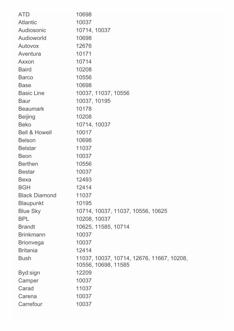
ATD 10698Atlantic 10037Audiosonic 10714, 10037Audioworld 10698Autovox 12676Aventura 10171Axxon 10714Baird 10208Barco 10556Base 10698Basic Line 10037, 11037, 10556Baur 10037, 10195Beaumark 10178Beijing 10208Beko 10714, 10037Bell & Howell 10017Belson 10698Belstar 11037Beon 10037Berthen 10556Bestar 10037Bexa 12493BGH 12414Black Diamond 11037Blaupunkt 10195Blue Sky 10714, 10037, 11037, 10556, 10625BPL 10208, 10037Brandt 10625, 11585, 10714Brinkmann 10037Brionvega 10037Britania 12414Bush 11037, 10037, 10714, 12676, 11667, 10208,
10556, 10698, 11585Byd:sign 12209Camper 10037Carad 11037Carena 10037Carrefour 10037

Cascade 10037Casio 10037Cathay 10037CCE 13782, 10037Celcus 12676, 11585Celebrity 10000Centrum 11037Centurion 10037Changhong 13434, 12769, 10508Chimei 12769Chun Yun 10000, 11150Chung Hsin 11150Clarivox 10037Clatronic 10037, 10714Clayton 11037Coby 13478CommercialSolutions
11447
Condor 10037Conrowa 10698Contec 10037Cosmel 10037CPTEC 10625Crown 10037, 10714, 10208, 11037Crypton 11667Curtis 12397Cyberpix 11667D-Vision 10037, 10556Daewoo 10037, 10556, 10178, 11150Dansai 10037, 10208Dantax 11037, 10714, 12676Datsura 10208Dawa 10037Daytron 10037De Graaf 10208Decca 10037Denver 10037Desmet 10037Diamant 10037
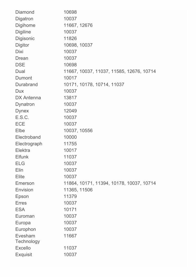
Diamond 10698Digatron 10037Digihome 11667, 12676Digiline 10037Digisonic 11826Digitor 10698, 10037Dixi 10037Drean 10037DSE 10698Dual 11667, 10037, 11037, 11585, 12676, 10714Dumont 10017Durabrand 10171, 10178, 10714, 11037Dux 10037DX Antenna 13817Dynatron 10037Dynex 12049E.S.C. 10037ECE 10037Elbe 10037, 10556Electroband 10000Electrograph 11755Elektra 10017Elfunk 11037ELG 10037Elin 10037Elite 10037Emerson 11864, 10171, 11394, 10178, 10037, 10714Envision 11365, 11506Epson 11379Erres 10037ESA 10171Euroman 10037Europa 10037Europhon 10037EveshamTechnology
11667
Excello 11037Exquisit 10037
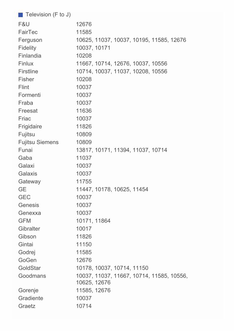
Television (F to J)
F&U 12676FairTec 11585Ferguson 10625, 11037, 10037, 10195, 11585, 12676Fidelity 10037, 10171Finlandia 10208Finlux 11667, 10714, 12676, 10037, 10556Firstline 10714, 10037, 11037, 10208, 10556Fisher 10208Flint 10037Formenti 10037Fraba 10037Freesat 11636Friac 10037Frigidaire 11826Fujitsu 10809Fujitsu Siemens 10809Funai 13817, 10171, 11394, 11037, 10714Gaba 11037Galaxi 10037Galaxis 10037Gateway 11755GE 11447, 10178, 10625, 11454GEC 10037Genesis 10037Genexxa 10037GFM 10171, 11864Gibralter 10017Gibson 11826Gintai 11150Godrej 11585GoGen 12676GoldStar 10178, 10037, 10714, 11150Goodmans 10037, 11037, 11667, 10714, 11585, 10556,
10625, 12676Gorenje 11585, 12676Gradiente 10037Graetz 10714

Granada 10208, 10037Grandin 10037, 10714, 11037, 10556Grundig 10195, 11223, 10556, 10037, 11667, 12676H-Buster 13620Haier 13620, 10698, 10037, 10508Hallmark 10178Hankook 10178Hannspree 11826Hanseatic 10037, 10714, 10625, 10556Hantarex 10037Hantor 10037Harwood 10037Hauppauge 10037HB 10714HCM 10037Heran 11826Herosonic 11826Highline 10037Hinari 10037, 10208HiPlus 11826Hisawa 10714Hisense 10556, 10508, 10208Hitachi 11643, 12676, 11576, 11585, 11691, 11037,
11667, 10037, 10150, 10178, 10508, 11150,12170
Hitachi Fujian 10150Hitec 10698Hoher 10714Hornyphon 10037Hua Tun 11150Hypson 10037, 10714, 10556, 11037Hyundai 10698, 12676, 11037Iberia 10037ICE 10037iLo 11394Imperial 10037Indiana 10037Inno Hit 11037, 11585Innova 10037
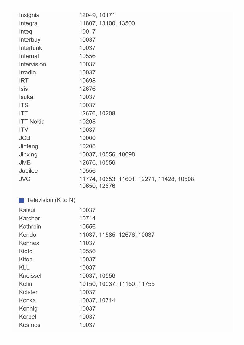
Insignia 12049, 10171Integra 11807, 13100, 13500Inteq 10017Interbuy 10037Interfunk 10037Internal 10556Intervision 10037Irradio 10037IRT 10698Isis 12676Isukai 10037ITS 10037ITT 12676, 10208ITT Nokia 10208ITV 10037JCB 10000Jinfeng 10208Jinxing 10037, 10556, 10698JMB 12676, 10556Jubilee 10556JVC 11774, 10653, 11601, 12271, 11428, 10508,
10650, 12676
Television (K to N)
Kaisui 10037Karcher 10714Kathrein 10556Kendo 11037, 11585, 12676, 10037Kennex 11037Kioto 10556Kiton 10037KLL 10037Kneissel 10037, 10556Kolin 10150, 10037, 11150, 11755Kolster 10037Konka 10037, 10714Konnig 10037Korpel 10037Kosmos 10037
Kunlun 10208Kupperbusch 12676L&S Electronic 10714Lavis 11037Lecson 10037Lenco 10037, 11037Leyco 10037LG 11840, 11860, 11423, 12731, 12182, 12358,
12362, 10178, 12424, 10037, 10714, 10017,10556, 10698
LiesenKotter 10037Lifetec 10037, 11037, 10714Linetech 12676Linsar 12676, 11667, 11585Local India Brand 10208Local MalaysiaBrand
10698
Lodos 11037Loewe 10633Logik 11037, 10698, 11585Luma 11037Lumatron 10037Lumenio 10037Lux May 10037Luxor 11037, 12676, 10208LXI 10178Madison 10037Magnavox 12372, 11454, 11506, 10171, 11365, 11755,
11867Magnum 10714, 10037Manesth 10037Manhattan 10037, 11037Marantz 10037, 10556Mark 10037, 10714Mastro 10698Masuda 10037Matsui 10037, 10195, 10208, 11037, 10714, 10556,
11667, 12676Matsushita 10650Maxent 11755
Maxess 12493Meck 10698Mediator 10037, 10556Medion 10714, 10037, 11037, 12676, 11667, 10556,
10698, 11585Megatron 10178MEI 11037Melectronic 10037, 10195, 10714Memorex 10178, 10150, 11037Mercury 10037Mermaid 10037Metronic 10625Metz 11037, 10195MGA 10150, 10178Micromaxx 10037, 10714, 11037Midland 10017Mikomi 11585, 11667Minato 10037Minerva 10195Ministry Of Sound 11667Minoka 10037Mitsubishi 10150, 11250, 12313, 10178, 10037, 10556,
11150, 11037, 11171Moree 10037Morgan's 10037Moserbaer 11585MTlogic 10714Mudan 10208Multitec 11037, 10037Multitech 10037Myryad 10556NAD 10037, 10178Naiko 10037Nakimura 10037National 10208, 10508NEC 12461, 10178, 10508, 10653, 11150Neckermann 10037, 10556
NEI 10037, 11037Neoka 11826

Netsat 10037NetTV 11755Neufunk 10556, 10714, 10037Nevir 12676New Sonic 11826New Tech 10037, 10556Newave 10178, 11150Nikkai 10037Nikkei 10714Nikko 10178Nokia 10208Norcent 11365Nordmende 10195, 11585, 10037, 10714, 11667Normerel 10037Novatronic 10037Novita 11585NPG 13434
Television (O to S)
Oceanic 10208OK Line 11037OK. 13434, 12676Okano 10037OKI 11667, 12676, 13434, 11585Omni 10698Onei 11667Onida 10653, 12414Onimax 10714Onix 10698Onkyo 11807, 13100, 13500Onn 11667Opera 10037, 10714Optimus 10650Orava 11037Orbit 10037Orion 10037, 10556, 10714, 11037, 12676Orline 10037Ormond 11037Osaki 10037, 10556
Osio 10037Osume 10037Otto Versand 10037, 10556, 10195Pacific 10714, 11037, 10556Palladium 10037, 10714, 10556Palsonic 12461, 10698, 10037Panama 10037Panasonic 11636, 11291, 11480, 11650, 10650, 13825,
12170, 10037, 10208, 10508Panavideo 13825Panavision 10037Panda 10208, 10508, 10698Penney 10178Perdio 10037Perfekt 10037Philco 13426, 12414, 10037, 10178Philips 10037, 12800, 10556, 11887, 11867, 11506,
12372, 12680, 11454, 10171, 11365, 10017,10000, 10178, 11394
Phocus 10714Phoenix 10037Phonola 10037, 10556Pioneer 11457, 10037, 10698, 11636, 12171PJ 11506Plantron 10037Playsonic 10714, 10037Polaroid 12676, 11826Powerpoint 10037, 10698Prima 12461Prinston 11037Pro Vision 10037, 10556, 10714Profitronic 10037Proline 10625, 10037, 11037, 12676Proscan 11447Prosonic 10714, 12676, 10037, 11585, 11667Protech 10037, 11037Proton 10178Pulsar 10017Pye 10037, 10556

Qingdao 10208Quadro 11667Quasar 11291, 10650Quelle 10037, 11037, 10195R-Line 10037Radiola 10037, 10556Radiomarelli 10037RadioShack 10037, 10178Radiotone 10037, 11037RCA 11447, 12746, 10625, 12434, 12932, 12187,
10000, 10178, 10618, 11454, 13426Realistic 10178Recor 10037Rectiligne 10037Red Star 10037Reflex 10037, 11037Relisys 11585Relon 11826Remotec 10037, 10171Reoc 10714Revox 10037RFT 10037Roadstar 11037, 10037, 10714Rowa 10698, 10037Runco 10017Saba 10625, 10714, 12676Sagem 10618Saivod 11037, 10037Salora 10208Sampo 11755, 10171, 10178, 10650Samsung 12051, 11632, 10618, 10037, 10556, 10178,
10208, 11150Sansui 10037, 10714Sanyo 10208, 11142, 11585, 12676, 12461, 11974,
12769, 10508, 11037, 11150, 11365, 11667SBR 10037, 10556Schaub Lorenz 10714, 12676, 11667Schneider 10037, 10556, 10714, 11037, 11585, 12676Schontech 11037
Scotch 10178Scott 10178Sears 10171, 10178Seelver 11037SEG 11037, 10037, 13434SEI 10037Sei-Sinudyne 10037Semp Toshiba 13793Sencor 10714Senzu 12493Serie Dorada 10178Shanghai 10208Sharp 11659, 12360, 10818, 11393, 12676, 10650,
11165, 11423Sheng Chia 11150Shintoshi 10037Shivaki 10178, 10037Siam 10037Siemens 10195, 10037Siera 10556, 10037Silva 10037Silva Schneider 10037SilverCrest 12676, 11037Sinudyne 10037SKY 10037Skyworth 12769, 10037, 10698Solavox 10037Soniko 10037Soniq 12493Sonitron 10208Sonneclair 10037Sonoko 10037Sonolor 10208Sontec 10037Sony 12778, 11825, 10810, 10000, 11651, 11505,
11167Soundesign 10178Soundwave 10037, 11037Sowa 10178, 11150
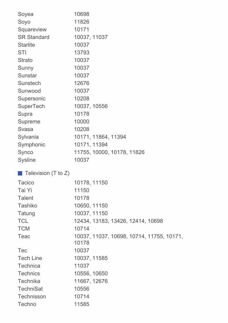
Soyea 10698Soyo 11826Squareview 10171SR Standard 10037, 11037Starlite 10037STI 13793Strato 10037Sunny 10037Sunstar 10037Sunstech 12676Sunwood 10037Supersonic 10208SuperTech 10037, 10556Supra 10178Supreme 10000Svasa 10208Sylvania 10171, 11864, 11394Symphonic 10171, 11394Synco 11755, 10000, 10178, 11826Sysline 10037
Television (T to Z)
Tacico 10178, 11150Tai Yi 11150Talent 10178Tashiko 10650, 11150Tatung 10037, 11150TCL 12434, 13183, 13426, 12414, 10698TCM 10714Teac 10037, 11037, 10698, 10714, 11755, 10171,
10178Tec 10037Tech Line 10037, 11585Technica 11037Technics 10556, 10650Technika 11667, 12676TechniSat 10556Technisson 10714Techno 11585
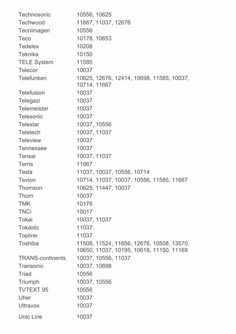
Technosonic 10556, 10625Techwood 11667, 11037, 12676Tecnimagen 10556Teco 10178, 10653Tedelex 10208Teknika 10150TELE System 11585Telecor 10037Telefunken 10625, 12676, 12414, 10698, 11585, 10037,
10714, 11667Telefusion 10037Telegazi 10037Telemeister 10037Telesonic 10037Telestar 10037, 10556Teletech 10037, 11037Teleview 10037Tennessee 10037Tensai 10037, 11037Terris 11667Tesla 11037, 10037, 10556, 10714Tevion 10714, 11037, 10037, 10556, 11585, 11667Thomson 10625, 11447, 10037Thorn 10037TMK 10178TNCi 10017Tokai 10037, 11037Tokaido 11037Topline 11037Toshiba 11508, 11524, 11656, 12676, 10508, 13570,
10650, 11037, 10195, 10618, 11150, 11169TRANS-continents 10037, 10556, 11037Transonic 10037, 10698Triad 10556Triumph 10037, 10556TVTEXT 95 10556Uher 10037Ultravox 10037
Unic Line 10037
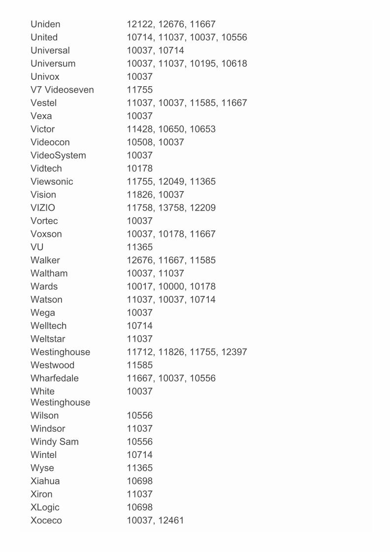
Uniden 12122, 12676, 11667United 10714, 11037, 10037, 10556Universal 10037, 10714Universum 10037, 11037, 10195, 10618Univox 10037V7 Videoseven 11755Vestel 11037, 10037, 11585, 11667Vexa 10037Victor 11428, 10650, 10653Videocon 10508, 10037VideoSystem 10037Vidtech 10178Viewsonic 11755, 12049, 11365Vision 11826, 10037VIZIO 11758, 13758, 12209Vortec 10037Voxson 10037, 10178, 11667VU 11365Walker 12676, 11667, 11585Waltham 10037, 11037Wards 10017, 10000, 10178Watson 11037, 10037, 10714Wega 10037Welltech 10714Weltstar 11037Westinghouse 11712, 11826, 11755, 12397Westwood 11585Wharfedale 11667, 10037, 10556WhiteWestinghouse
10037
Wilson 10556Windsor 11037Windy Sam 10556Wintel 10714Wyse 11365Xiahua 10698Xiron 11037XLogic 10698Xoceco 10037, 12461
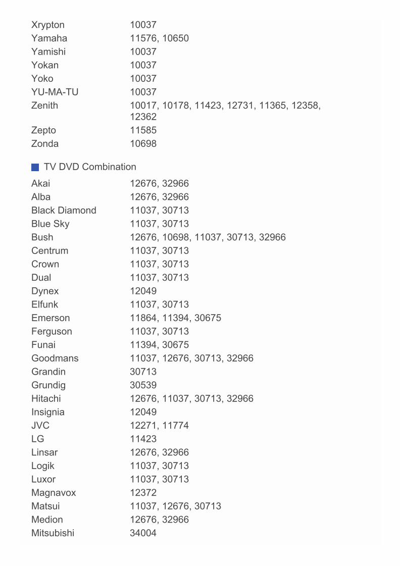
Xrypton 10037Yamaha 11576, 10650Yamishi 10037Yokan 10037Yoko 10037YU-MA-TU 10037Zenith 10017, 10178, 11423, 12731, 11365, 12358,
12362Zepto 11585Zonda 10698
TV DVD Combination
Akai 12676, 32966Alba 12676, 32966Black Diamond 11037, 30713Blue Sky 11037, 30713Bush 12676, 10698, 11037, 30713, 32966Centrum 11037, 30713Crown 11037, 30713Dual 11037, 30713Dynex 12049Elfunk 11037, 30713Emerson 11864, 11394, 30675Ferguson 11037, 30713Funai 11394, 30675Goodmans 11037, 12676, 30713, 32966Grandin 30713Grundig 30539Hitachi 12676, 11037, 30713, 32966Insignia 12049JVC 12271, 11774LG 11423Linsar 12676, 32966Logik 11037, 30713Luxor 11037, 30713Magnavox 12372Matsui 11037, 12676, 30713Medion 12676, 32966Mitsubishi 34004
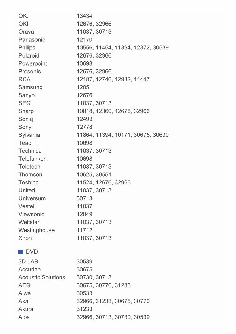
OK. 13434OKI 12676, 32966Orava 11037, 30713Panasonic 12170Philips 10556, 11454, 11394, 12372, 30539Polaroid 12676, 32966Powerpoint 10698Prosonic 12676, 32966RCA 12187, 12746, 12932, 11447Samsung 12051Sanyo 12676SEG 11037, 30713Sharp 10818, 12360, 12676, 32966Soniq 12493Sony 12778Sylvania 11864, 11394, 10171, 30675, 30630Teac 10698Technica 11037, 30713Telefunken 10698Teletech 11037, 30713Thomson 10625, 30551Toshiba 11524, 12676, 32966United 11037, 30713Universum 30713Vestel 11037Viewsonic 12049Weltstar 11037, 30713Westinghouse 11712Xiron 11037, 30713
DVD
3D LAB 30539Accurian 30675Acoustic Solutions 30730, 30713AEG 30675, 30770, 31233Aiwa 30533Akai 32966, 31233, 30675, 30770Akura 31233Alba 32966, 30713, 30730, 30539
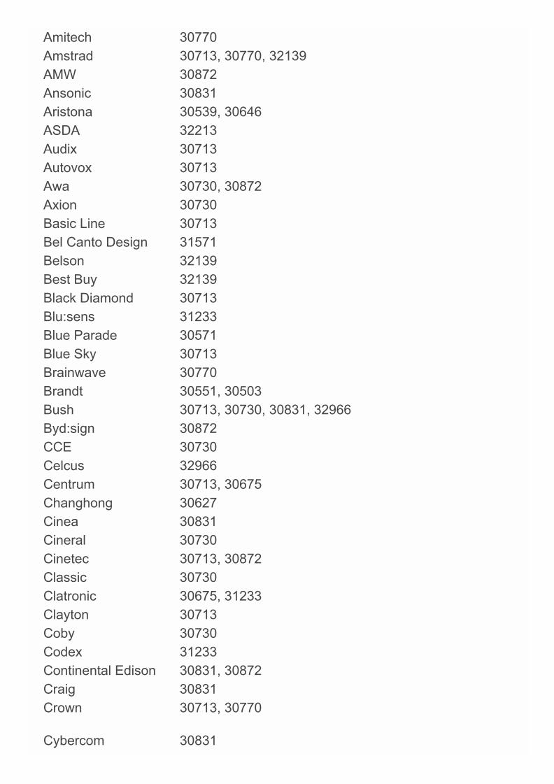
Amitech 30770Amstrad 30713, 30770, 32139AMW 30872Ansonic 30831Aristona 30539, 30646ASDA 32213Audix 30713Autovox 30713Awa 30730, 30872Axion 30730Basic Line 30713Bel Canto Design 31571Belson 32139Best Buy 32139Black Diamond 30713Blu:sens 31233Blue Parade 30571Blue Sky 30713Brainwave 30770Brandt 30551, 30503Bush 30713, 30730, 30831, 32966Byd:sign 30872CCE 30730Celcus 32966Centrum 30713, 30675Changhong 30627Cinea 30831Cineral 30730Cinetec 30713, 30872Classic 30730Clatronic 30675, 31233Clayton 30713Coby 30730Codex 31233Continental Edison 30831, 30872Craig 30831Crown 30713, 30770
Cybercom 30831
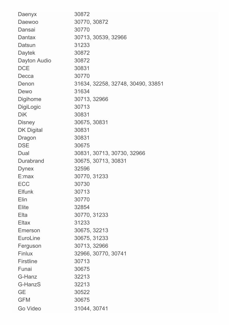
Daenyx 30872Daewoo 30770, 30872Dansai 30770Dantax 30713, 30539, 32966Datsun 31233Daytek 30872Dayton Audio 30872DCE 30831Decca 30770Denon 31634, 32258, 32748, 30490, 33851Dewo 31634Digihome 30713, 32966DigiLogic 30713DiK 30831Disney 30675, 30831DK Digital 30831Dragon 30831DSE 30675Dual 30831, 30713, 30730, 32966Durabrand 30675, 30713, 30831Dynex 32596E:max 30770, 31233ECC 30730Elfunk 30713Elin 30770Elite 32854Elta 30770, 31233Eltax 31233Emerson 30675, 32213EuroLine 30675, 31233Ferguson 30713, 32966Finlux 32966, 30770, 30741Firstline 30713Funai 30675G-Hanz 32213G-HanzS 32213GE 30522GFM 30675Go Video 31044, 30741
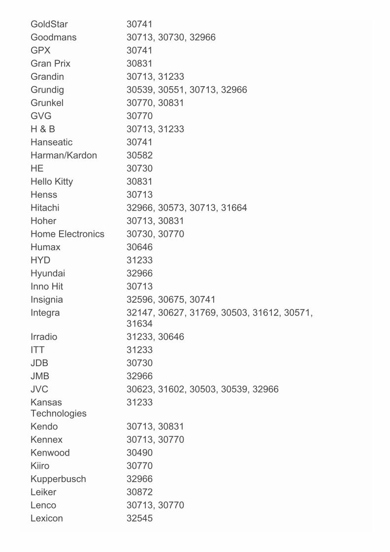
GoldStar 30741Goodmans 30713, 30730, 32966GPX 30741Gran Prix 30831Grandin 30713, 31233Grundig 30539, 30551, 30713, 32966Grunkel 30770, 30831GVG 30770H & B 30713, 31233Hanseatic 30741Harman/Kardon 30582HE 30730Hello Kitty 30831Henss 30713Hitachi 32966, 30573, 30713, 31664Hoher 30713, 30831Home Electronics 30730, 30770Humax 30646HYD 31233Hyundai 32966Inno Hit 30713Insignia 32596, 30675, 30741Integra 32147, 30627, 31769, 30503, 31612, 30571,
31634Irradio 31233, 30646ITT 31233JDB 30730JMB 32966JVC 30623, 31602, 30503, 30539, 32966KansasTechnologies
31233
Kendo 30713, 30831Kennex 30713, 30770Kenwood 30490Kiiro 30770Kupperbusch 32966Leiker 30872Lenco 30713, 30770Lexicon 32545
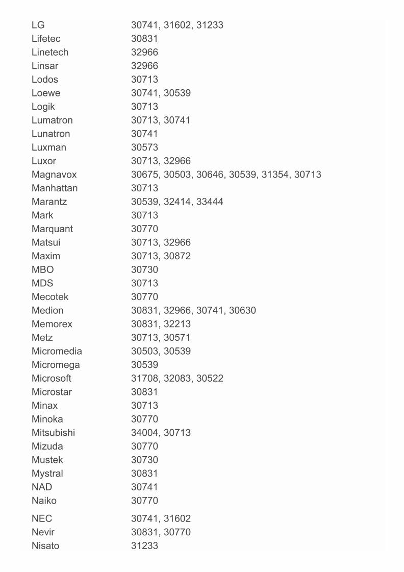
LG 30741, 31602, 31233Lifetec 30831Linetech 32966Linsar 32966Lodos 30713Loewe 30741, 30539Logik 30713Lumatron 30713, 30741Lunatron 30741Luxman 30573Luxor 30713, 32966Magnavox 30675, 30503, 30646, 30539, 31354, 30713Manhattan 30713Marantz 30539, 32414, 33444Mark 30713Marquant 30770Matsui 30713, 32966Maxim 30713, 30872MBO 30730MDS 30713Mecotek 30770Medion 30831, 32966, 30741, 30630Memorex 30831, 32213Metz 30713, 30571Micromedia 30503, 30539Micromega 30539Microsoft 31708, 32083, 30522Microstar 30831Minax 30713Minoka 30770Mitsubishi 34004, 30713Mizuda 30770Mustek 30730Mystral 30831NAD 30741Naiko 30770
NEC 30741, 31602Nevir 30831, 30770Nisato 31233
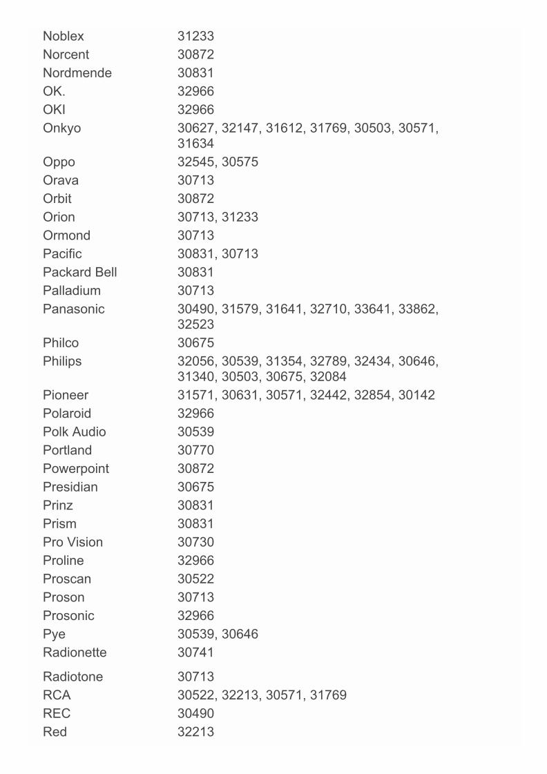
Noblex 31233Norcent 30872Nordmende 30831OK. 32966OKI 32966Onkyo 30627, 32147, 31612, 31769, 30503, 30571,
31634Oppo 32545, 30575Orava 30713Orbit 30872Orion 30713, 31233Ormond 30713Pacific 30831, 30713Packard Bell 30831Palladium 30713Panasonic 30490, 31579, 31641, 32710, 33641, 33862,
32523Philco 30675Philips 32056, 30539, 31354, 32789, 32434, 30646,
31340, 30503, 30675, 32084Pioneer 31571, 30631, 30571, 32442, 32854, 30142Polaroid 32966Polk Audio 30539Portland 30770Powerpoint 30872Presidian 30675Prinz 30831Prism 30831Pro Vision 30730Proline 32966Proscan 30522Proson 30713Prosonic 32966Pye 30539, 30646Radionette 30741
Radiotone 30713RCA 30522, 32213, 30571, 31769REC 30490Red 32213
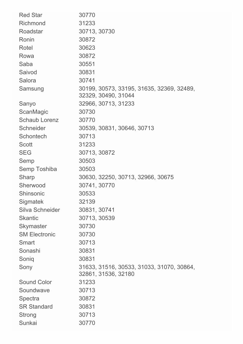
Red Star 30770Richmond 31233Roadstar 30713, 30730Ronin 30872Rotel 30623Rowa 30872Saba 30551Saivod 30831Salora 30741Samsung 30199, 30573, 33195, 31635, 32369, 32489,
32329, 30490, 31044Sanyo 32966, 30713, 31233ScanMagic 30730Schaub Lorenz 30770Schneider 30539, 30831, 30646, 30713Schontech 30713Scott 31233SEG 30713, 30872Semp 30503Semp Toshiba 30503Sharp 30630, 32250, 30713, 32966, 30675Sherwood 30741, 30770Shinsonic 30533Sigmatek 32139Silva Schneider 30831, 30741Skantic 30713, 30539Skymaster 30730SM Electronic 30730Smart 30713Sonashi 30831Soniq 30831Sony 31633, 31516, 30533, 31033, 31070, 30864,
32861, 31536, 32180Sound Color 31233Soundwave 30713Spectra 30872SR Standard 30831Strong 30713Sunkai 30770

Sunstech 30831, 32139, 32966Supratech 32139Sylvania 30675, 30630Symphonic 30675Sytech 30831Tandberg 30713Targa 30741Tascam 31818Tatung 30770TBoston 32139Tchibo 30741TCM 30741Teac 30571, 30675, 30741, 31818, 32139, 34004Technica 30713Technics 30490Technika 30770, 30831Technosonic 30730Techwood 30713, 32966Telefunken 30551, 32966Teletech 30713Tensai 30770Theta Digital 30571Thomson 30551, 30522, 30831Tokai 31233Toshiba 30503, 32705, 32277, 31769, 33157, 32966,
32551TRANS-continents 30831, 30872, 31233Transonic 30730Trevi 30831TVE 30713United 30713, 30675, 30730, 31233Universum 30713, 30741Urban Concepts 30503Venturer 31769Vestel 30713VIZIO 32563Voxson 30831, 30730Waitec 30730, 31233Walker 32966
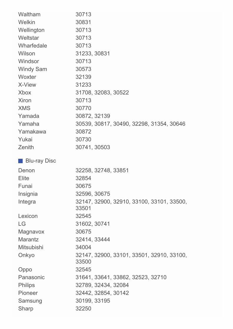
Waltham 30713Welkin 30831Wellington 30713Weltstar 30713Wharfedale 30713Wilson 31233, 30831Windsor 30713Windy Sam 30573Woxter 32139X-View 31233Xbox 31708, 32083, 30522Xiron 30713XMS 30770Yamada 30872, 32139Yamaha 30539, 30817, 30490, 32298, 31354, 30646Yamakawa 30872Yukai 30730Zenith 30741, 30503
Blu-ray Disc
Denon 32258, 32748, 33851Elite 32854Funai 30675Insignia 32596, 30675Integra 32147, 32900, 32910, 33100, 33101, 33500,
33501Lexicon 32545LG 31602, 30741Magnavox 30675Marantz 32414, 33444Mitsubishi 34004Onkyo 32147, 32900, 33101, 33501, 32910, 33100,
33500Oppo 32545Panasonic 31641, 33641, 33862, 32523, 32710Philips 32789, 32434, 32084Pioneer 32442, 32854, 30142Samsung 30199, 33195Sharp 32250
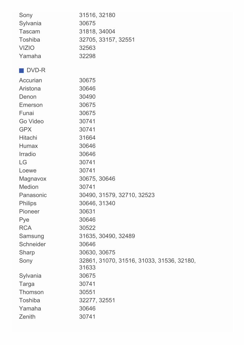
Sony 31516, 32180Sylvania 30675Tascam 31818, 34004Toshiba 32705, 33157, 32551VIZIO 32563Yamaha 32298
DVD-R
Accurian 30675Aristona 30646Denon 30490Emerson 30675Funai 30675Go Video 30741GPX 30741Hitachi 31664Humax 30646Irradio 30646LG 30741Loewe 30741Magnavox 30675, 30646Medion 30741Panasonic 30490, 31579, 32710, 32523Philips 30646, 31340Pioneer 30631Pye 30646RCA 30522Samsung 31635, 30490, 32489Schneider 30646Sharp 30630, 30675Sony 32861, 31070, 31516, 31033, 31536, 32180,
31633Sylvania 30675Targa 30741Thomson 30551Toshiba 32277, 32551Yamaha 30646Zenith 30741

VCR
DirecTV 20739Humax 20739Panasonic 20616Philips 20739RCN 20739ReplayTV 20616Sonic Blue 20616Sony 20636TiVo 20739, 20636
Cable Set Top Box (A to E)
3 Rivers TelephoneCooperative
01376
Accelplus 01376, 01877, 01982Access CableTelevision
01376, 01877, 01982
AccessCommunications
01376, 01877
AceCommunications
02586
ACTV Cablevision 01376, 01877, 01982Adams Cable TV 01376ADB 02586, 01920, 01481, 01998, 02437, 03028AdvancedBroadband
01376, 01877, 01982
AdvancedTelemedia
01376, 01877, 01982
Airwave Networks 01376, 01982Akado 02043Alabama Broadband 01376Alcom 02437Algona MunicipalUtilities
01376, 01877, 01982
All WestCommunications
01376
AlleghanyCablevision
01376, 01877, 01982
AllegianceCommunications
01376
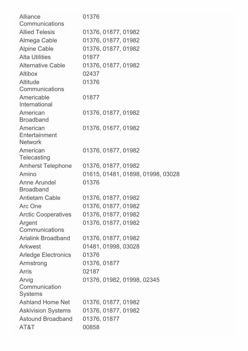
AllianceCommunications
01376
Allied Telesis 01376, 01877, 01982Almega Cable 01376, 01877, 01982Alpine Cable 01376, 01877, 01982Alta Utilities 01877Alternative Cable 01376, 01877, 01982Altibox 02437AltitudeCommunications
01376
AmericableInternational
01877
AmericanBroadband
01376, 01877, 01982
AmericanEntertainmentNetwork
01376, 01877, 01982
AmericanTelecasting
01376, 01877, 01982
Amherst Telephone 01376, 01877, 01982Amino 01615, 01481, 01898, 01998, 03028Anne ArundelBroadband
01376
Antietam Cable 01376, 01877, 01982Arc One 01376, 01877, 01982Arctic Cooperatives 01376, 01877, 01982ArgentCommunications
01376, 01877, 01982
Arialink Broadband 01376, 01877, 01982Arkwest 01481, 01998, 03028Arledge Electronics 01376Armstrong 01376, 01877Arris 02187ArvigCommunicationSystems
01376, 01982, 01998, 02345
Ashland Home Net 01376, 01877, 01982Askivision Systems 01376, 01877, 01982Astound Broadband 01376, 01877AT&T 00858

ATCCommunications
01376
Atlantic Broadband 01877, 01376ATMC 01376, 01982, 01998, 03028Atwood Cable 01376, 01877, 01982Aurora Cable TV 01376, 01877, 01982AyrshireCommunications
01376, 01877, 01982
B & C Cablevision 01376, 01877, 01982B & L Technologies 01376, 01877, 01982Bailey Cable TV 01376, 01877, 01982Baja Broadband 01376Baldwin CountyInternet
01376, 01877, 01982
Baldwin Telecom 01877Ballard RuralTelephoneCooperative
02586
Barbourville UtilityCommission
01376, 01877, 01982
Bardstown Cable 01376, 01877, 01982BascomCommunications
01376, 01877, 01982
Base Cablevision 01376, 01877, 01982Bay Cablevision 01376, 01877, 01982Bay City Cablevision 01376, 01877, 01982Bay CountryCommunications
01376, 01877, 01982
Bay CreekCommunications
01376
BaylandCommunications
02586
Bayou Cable 01376, 01877, 01982Beamspeed 01376, 01877, 01982Beaver CreekTelephone
01877, 01982
Beaver Valley Cable 01376, 01877, 01982Beck's CableSystems
01376, 01877, 01982
Bee Line Cable 01376Beeline 03028
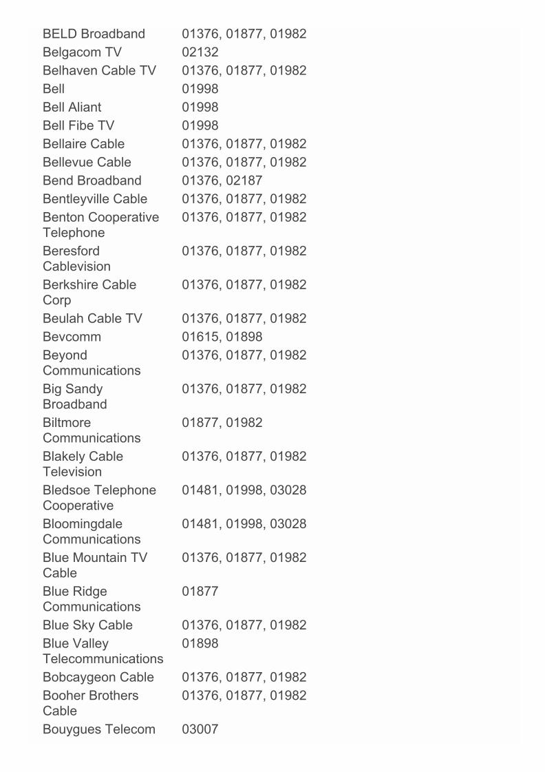
BELD Broadband 01376, 01877, 01982Belgacom TV 02132Belhaven Cable TV 01376, 01877, 01982Bell 01998Bell Aliant 01998Bell Fibe TV 01998Bellaire Cable 01376, 01877, 01982Bellevue Cable 01376, 01877, 01982Bend Broadband 01376, 02187Bentleyville Cable 01376, 01877, 01982Benton CooperativeTelephone
01376, 01877, 01982
BeresfordCablevision
01376, 01877, 01982
Berkshire CableCorp
01376, 01877, 01982
Beulah Cable TV 01376, 01877, 01982Bevcomm 01615, 01898BeyondCommunications
01376, 01877, 01982
Big SandyBroadband
01376, 01877, 01982
BiltmoreCommunications
01877, 01982
Blakely CableTelevision
01376, 01877, 01982
Bledsoe TelephoneCooperative
01481, 01998, 03028
BloomingdaleCommunications
01481, 01998, 03028
Blue Mountain TVCable
01376, 01877, 01982
Blue RidgeCommunications
01877
Blue Sky Cable 01376, 01877, 01982Blue ValleyTelecommunications
01898
Bobcaygeon Cable 01376, 01877, 01982Booher BrothersCable
01376, 01877, 01982
Bouygues Telecom 03007
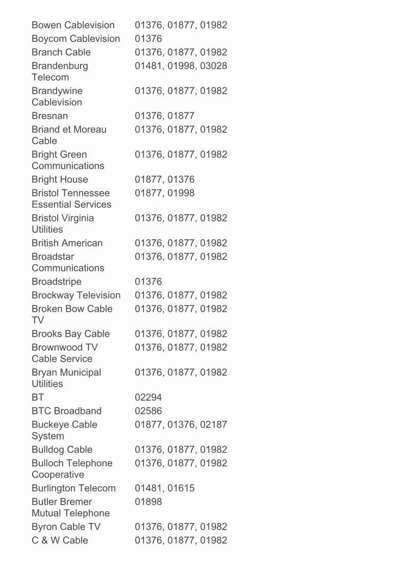
Bowen Cablevision 01376, 01877, 01982Boycom Cablevision 01376Branch Cable 01376, 01877, 01982BrandenburgTelecom
01481, 01998, 03028
BrandywineCablevision
01376, 01877, 01982
Bresnan 01376, 01877Briand et MoreauCable
01376, 01877, 01982
Bright GreenCommunications
01376, 01877, 01982
Bright House 01877, 01376Bristol TennesseeEssential Services
01877, 01998
Bristol VirginiaUtilities
01376, 01877, 01982
British American 01376, 01877, 01982BroadstarCommunications
01376, 01877, 01982
Broadstripe 01376Brockway Television 01376, 01877, 01982Broken Bow CableTV
01376, 01877, 01982
Brooks Bay Cable 01376, 01877, 01982Brownwood TVCable Service
01376, 01877, 01982
Bryan MunicipalUtilities
01376, 01877, 01982
BT 02294BTC Broadband 02586Buckeye CableSystem
01877, 01376, 02187
Bulldog Cable 01376, 01877, 01982Bulloch TelephoneCooperative
01376, 01877, 01982
Burlington Telecom 01481, 01615Butler BremerMutual Telephone
01898
Byron Cable TV 01376, 01877, 01982C & W Cable 01376, 01877, 01982
C.L. Davis CableServices
01376, 01877, 01982
Cable &Communications
01376
Cable America 01376, 01877Cable Axion Digitel 01376CableCommunications ofWillsboro
01376, 01877, 01982
Cable Cooperative 01376, 01877, 01982Cable DevelopmentCorporation
01376, 01877, 01982
Cable ManagementAssocication
01376, 01877, 01982
Cable Montana 01376, 01877, 01982Cable Nebraska 01376, 01877, 01982Cable Of TheCarolinas
01376, 01877, 01982
Cable One 01376, 01877Cable Plus 01376, 01877, 01982Cable Suite 01376Cable Tech CableTV
01376, 01877, 01982
Cable TV ofCamrose
01376
Cable TV of EastAlabama
01376, 01877, 01982
Cable TV of SlaveLake
01376, 01877, 01982
Cable TV of St. Paul 01376, 01877, 01982Cable VisionServices
01877
Cablecom 01582Cablecom Mexico 01376Cablemas 01376, 01877Cablenet 01376, 01877, 01982CableSouth Media 01376, 01877, 01982CableviewCommunications
01376, 01877, 01982
Cablevision 01877, 01376Cablevision du Nord 01376

Cablevision ofMarion County
01376
Cablevision T.R.P. 01376, 01877, 01982Cabovis 02436Caiway 02015, 0660CalNeva Broadband 01376, 01877, 01982CalTel Connections 02586CameronCommunications
01376, 01877, 01982
CAMS Cable 01376, 01877, 01982Canby Telcom 01481Cannon ValleyCablevision
01481, 01998, 03028
Caprock TV 01376, 01877, 01982Carnegie Cable 01376, 01877, 01982Carolina MountainCable
01376, 01877, 01982
CarrCommunications
01376, 01877, 01982
CarrellCommunications
01376, 01877, 01982
CAS Cable 01376CascadeCommunications
01376, 01877, 01982
Casey Cable 01376, 01877, 01982Caspian CommunityTV
01376, 01877, 01982
Cass Cable 01376Castle CableService
01376, 01877, 01982
Catalina Cable 01376, 01877, 01982Catawba Services 01376, 01877, 01982CBN 01376, 01877, 01982CBPU Cable 01376, 01877, 01982CCAP 01877CDE Lightband 00858, 01615, 02586Cedar Falls Utilities 01376CelectCommunications
01376, 01877, 01982
Cencom 01376, 01877, 01982

CentraComInteractive
01376, 01877, 01982
Central TexasCommunications
01376, 01877, 01982
Central Valley Cable 01376, 01877, 01982Centre TV Cable 01376, 01877, 01982Centrovision 01376, 01877, 01982CenturyCommunications
01376, 01877, 01982
Century Telephone 01376, 01877, 01982CenturyLink 01998CenturyTelTeleVideo
01376, 01877, 01982
Chambers Cable 01376ChampionBroadband
01376, 01877, 01982
ChaparralCablevision
01376, 01877, 01982
Chariton ValleyCommunications
01376, 01877, 01982
Charter 01376, 01877, 02187ChatmossCablevision
01376, 01877, 01982
ChequamegonTelephoneCooperative
01898, 01615
ChesneeCommunications
01376, 01877, 01982
Chester Telephone 01376ChinookProgressive Club TV
01376, 01877, 01982
Chippewa ValleyCable
01376, 01877, 01982
Choice Cable TV 01376, 01877, 01982ChoiceCommunications
01376, 01877, 01982
Choice Television 01376, 01877, 01982ChoiceCable 01376Christy Cablevision 01376, 01877, 01982CimTel 01376

Cincinnati Bell 01877, 01376Circle Bar CableTelevision
01376, 01877, 01982
Cisco 01877, 01982, 00858, 02589, 03028, 02132,02345, 01582, 01883, 02378, 02401, 03265
Citizens Cable 01376Citizens Cable TV 01376Citizens Cablevision 01481Citizens MutualTelephone
01376, 01877, 01982
Citizens Telecom 01376, 01877, 01982Citizens Telephone 02586City Cablevision 01376, 01877, 01982City of BarnesvilleCable
01376, 01877, 01982
City of BaxterSprings Cable
01376, 01877, 01982
City of HawardenCable
01376, 01877, 01982
City of NorwayCable
01376, 01877, 01982
City of QuitmanCable
01376, 01877, 01982
City Of Salisaw 01376City of Sumas TVCable System
01376, 01877, 01982
City West 01376Citycable 03477Clarence Telephone 01376, 01877, 01982Claro 01376Clear CreekCommunications
01376
Clearview Cable 01376, 01877, 01982Clearview Partners 01376, 01877, 01982Clearview TV Cable 01376, 01877, 01982Clearvision CableTV
01376, 01877, 01982
Click Network 01376ClickOne 01376, 01877, 01982Clinton Cable 01376, 01877, 01982

CLTCommunications
01376, 01877, 01982
ClubInternet 02132CMACommunications
01376
CNS Television 01376, 01877, 01982Coast CableCommunications
01376
Coast Cablevision 01376, 01877, 01982CoastCommunications
01376
Coastal Link 01376Coaxial Cable TV 01376, 01877, 01982Cobridge 01376CobridgeCommunications
01376
Cogeco 01376, 01877, 01982Colane Cable TV 01376, 01877, 01982Colfax HighlineCable
01376, 01877, 01982
Collinsville Cable 01376, 01877, 01982Colonial Cablevision 01376, 01877, 01982ColtonTel 02378Columbia Powerand Water
01376, 01877
ColumbusTelephone
01376
Com Hem 00660, 02015Com-Link 01376, 01877, 01982Comcast 01376, 01982, 01877, 02187CommunicationServices
01376, 01877, 01982
Communicomm 01376, 01877, 01982Community AntennaService
01376, 01877, 01982
Community AntennaSystem
01376, 01877, 01982
Community Cable &Broadband
01376
Community CableService
01376, 01877, 01982
CommunityCommunications
01376, 01877, 01982
Community Telecom 01376, 01877, 01982CommunityTelevision
01376, 01877
Compas Cable 01376, 01877, 01982CompleteCommunicationServices
01376, 01877, 01982
Comserv Ltd 01376, 01877, 01982ComSouth 01376, 01877, 01982ComSpanCommunications
01481, 01898
Comstar Cable TV 01376, 01877, 01982Consolidated Cable 01376, 01877, 01982ConsolidatedCommunications
01376
Conuma CableSystems
01376, 01877, 01982
Conway CorporationCable TV
01376, 01877, 01982
Conxxus 01376, 01877, 01982Coon CreekTelephone
01376
Coon RapidsMunicipal Utilities
01376, 01877, 01982
Coop CSCF 01376CooperativeTelevision Godahl
01376, 01877, 01982
CoopTel 00858, 01615, 01898Coosa Cable 01376Copper MountainMetropolitan
01376, 01877, 01982
Country Cable 01376, 01877, 01982Country Cable TV 01376, 01877, 01982Country Cablevision 01376Country CablevisionLtd.
01376
Cowley Telecable 01376, 01877, 01982Cox 01877, 01376
Craig Cable TV 01376, 01877, 01982Craw-KanTelephoneCooperative
02586
Crestview Cable 01376, 01877, 01982Cross Country TV 01376, 01877, 01982CrosslakeCommunications
01376, 01877, 01982
Crow Cable TV 01376, 01877, 01982CRRS-TV 01376CRST TelephoneAuthority
01481, 01998, 03028
Crystal Cable TV 01376, 01877, 01982CSI Cable 01376, 01877, 01982CT & R Cable 01376, 01877, 01982CTC 01376CunninghamTelephone & Cable
01376
Curtis Cable TV 01376, 01877, 01982CUTV 01376, 01877, 01982CWA Cable 01376, 01877, 01982D & D CableSystems
01376, 01877, 01982
D & PCommunications
01376
Daeryung 01877Dairyland CableSystems
01376, 01877, 01982
Dakota CentralTelecommunications
02345
Dalton CableTelevision
01877, 01982
Darty Box 02436DavisCommunications
01376, 01877, 01982
Dawson CityTelevision
01376, 01877, 01982
DCA Cablevision 01376, 01877, 01982DDD Cablevision 01376, 01877, 01982Dean Hill Cable 01376, 01877, 01982Dean's Cablevision 01376, 01877, 01982
Decca Cable 01376, 01877, 01982Deffner Cable TV 01376, 01877, 01982Delhi Telephone 01376, 01877, 01982Delta 02015, 00660Delta Cable 01376Demopolis CATV 01376, 01877, 01982Denali TV 01376, 01877, 01982Dery Telecom 01376Deutsche Telekom 02132Dickey RuralNetworks
01376, 01877, 01982
Digeo 02187DiodeCommunications
01376, 01877, 01982
DiverseCommunications
01898, 01982
Dixie Cable TV 01376, 01877, 01982Dixon Telephone 01376, 01877, 01982DMS Cable 01376, 01877, 01982DownsvilleCommunity Antenna
01376, 01877, 01982
Doylestown CableTV
01376, 01877, 01982
Drummond CableTV
01376, 01877, 01982
DTC 01376, 01877, 01982Du 02401Dumont Telephone 01376, 01877, 01982Duncan Cable TV 01376, 01877, 01982Eagle Broadband 01481, 01998, 03028Eagle Cablevision 01376, 01877, 01982EagleCommunications
01376, 02187
Eagle ValleyTelephone
01481, 01998, 03028
EagleVisionWireless TVServices
01376, 01877, 01982
East ArkansasVideo
01376
East Cleveland 01376, 01877, 01982

CableEast Texas Cable 01376, 01877, 01982Eastern Cable 01376, 01877, 01982EastLink 01376Easton Cable 01877EasyTEL 01481, 01998, 03028Eatel 01877Echostar 03452Electron Enterprises 01376, 01877, 01982Elk River Cable TV 01376, 01877, 01982Elkhart TV Cable 01376, 01877, 01982Emery TelcomVideo
01376, 01877, 01982
Emily CoopTelephone
01481, 01615
EnhancedTelecommunications
01376
EnTouch 01376EPB of Chattanooga 00858Escape Broadband 01376, 01877, 01982Eston CATVCooperative
01376, 01877, 01982
ETAN Industries 01376, 01877, 01982Etex 02586Execulink 01376Eyecom 01376, 01877, 01982
Cable Set Top Box (F to J)
F & B Telephone 02586FairPointCommunications
01376, 01877, 01982
Falls Earth Station 01376, 01877, 01982FamilyViewCablevision
01376, 01877, 01982
Fannettsburg CableTV
01376, 01877, 01982
Farmer & MerchantMutual
01376, 01877, 01982
Farmer's TelephoneCooperative
01998, 03028
FarmersIndependentTelephone
01376, 01877, 01982
Farmers MutualTelephone
01376, 01877, 01982
Fayetteville ElectricSystem
01877
FederatedTelephone
01376
Fenton Cablevision 01376, 01877, 01982FiberCast CableCommunications
01376, 01877, 01982
FiberNet Monticello 01376, 01877, 01982Fibrant 01376, 01877, 01982FidelityCommunications
01376
First Cable OfMissouri
01376, 01877, 01982
FirstMile 01376, 01877, 01982Flint Cable TV 01376, 01877, 01982Florida Cable 01376Foothills RuralTelephoneCooperative
01877
Forsyth CableNet 01376, 01877, 01982Fort JenningsCommunications
02586
Fort Towson Cable 01376, 01877, 01982FosterCommunications
01376, 01877, 01982
Frank Howard TVCable
01376, 01877, 01982
Frankfort PlantBoard Cable
01376
Freebox 01976FTC 01877, 01982, 01376Full Channel TV 01376, 01877, 01982Full ChoiceCommunications
01376, 01877, 01982
Fusion Broadband 01376, 01877, 01982Futuristic 01376, 01877, 01982
CablevisionGalaxy AmericanCommunication
01376, 01877, 01982
Galaxy Cable 01376, 01877, 01982GardonvilleCooperativeTelephone
01998
GatehouseNetworks
01376, 01877, 01982
GauthierCablevision &Electric
01376, 01877, 01982
GCI 01877GeneralCommunications
01376
Genext 01376, 01877, 01982Geraldine Cable TV 01376, 01877, 01982Get Real Cable 01376, 01877, 01982GEUS 01376, 01877, 01982GiantCommunications
01376, 01877, 01982
Giles-CraigCommunications
01376, 01877, 01982
Gilmer CableTelevision
01376, 01877, 01982
Glasgow ElectricPlant Board
01376, 01877, 01982
Glass AntennaSystems
01376, 01877, 01982
GlenwoodTelecommunications
01376
Glide Cablevision 01376, 01877, 01982Globalcom 01376, 01877, 01982Golden BeltTelephone
02586
GoldenCommunications
01376, 01877, 01982
Golden RainFoundation
01376, 01877, 01982
Golden Valley Cable 01376, 01877, 01982Golden West 01376, 01877, 01982
TelecommunicationsGoldfieldCommunications
01376, 01877, 01982
GorhamCommunications
01481
Gowrie Cablevision 01376, 01877, 01982Grafton CableCommunications
01376, 01877, 01982
Grand River Cable 01376, 01877, 01982GrandeCommunications
01877, 01376
Great PlainsCommunications
01376
Green HillsCommunications
01376, 01877, 01982
Greene CountyCable TV
01376, 01877, 01982
GreenlightCommunityBroadband
01376, 01877, 01982
Gridley Cable 01376, 01877, 01982GriswoldCooperativeTelephone
01481, 01998, 03028
Grove Cable 01376, 01877, 01982Grundy CenterUtilities
01376, 01877
GTI 01481, 01998, 03028Guadalupe Valley 01877Haefele TV 01376, 01877, 01982Haines Cable TV 01376, 01877, 01982Hall BeachCooperative
01376, 01877, 01982
Hamilton CountyCable TV
01877, 01982, 01376
Hancel 01376, 01877, 01982Hargray 01376, 01877, 01982Harlan CommunityTV
01376
Harlan MunicipalUtilities
01376
Harmony Cable TV 01376, 01877, 01982Harris Broadband 01376HarrisonvilleTelephone
02586
Harron Metrocast 01376, 01877Hart Cable 01376, 01877, 01982Hart Electric 01376, 01877, 01982Hartelco 01376, 01877, 01982Hastings CableVision
01376, 01877, 01982
Hathw@y 02043Hawaiian Telcom 03028HBC 01376, 01877, 01982HBLCommunications
01376, 01877, 01982
HCS 01376, 01877, 01982Healthcare CableSystems
01376, 01877, 01982
Heart of IowaCommunications
01376, 01877, 01982
Heartland Cable 01376, 01877, 01982Heartland WirelessCommunications
01376, 01877, 01982
Heck's TV & Cable 01376, 01877, 01982HendersonTelephone
01376, 01877, 01982
HermosaCablevision
01376, 01877, 01982
Herr Cable 01376, 01877, 01982HFU Television 01376, 01877, 01982HiawathaBroadband
01376, 01877, 01982
HickoryTech 01898High PlainsCablevision
01376, 01877, 01982
Highland 01376, 01877, 01982Hill TopCommunications
01376, 01877, 01982
Hinton CATV 01376, 01877, 01982HLM Cable Corp 01376, 01877, 01982
HomeTel 01376Hometown Cable 01376, 01877, 01982Hometown Utilicom 01376, 01877, 01982Hood CanalCablevision
01376
Hoonah CommunityTelevision
01376, 01877, 01982
Hooper Telephone 01376, 01877, 01982Horizon Cable TV 01376, 02586Horizon Telecom 02586Horry TelephoneCooperative
01376, 01877, 01982
Hospers Telephone 01376, 01877, 01982Hotwire 02586Houston Cable 01376, 01877, 01982Hrvatski Telekom 02132HTCCommunications
01481, 01998, 03028
HTC Services 01376, 01877, 01982Humax 00660, 02620, 02043, 02165HunTel Systems 01376HuxleyCommunications
01376, 01877, 01982
Hydaburg Cable TV 01376, 01877, 01982HYDE CountyCablevision
01376, 01877, 01982
i-CAN 02437I-Speed 01376, 01877, 01982ICE Cable Holdings 01376ICSCommunications
01376, 01877, 01982
Illini Cablevision OfIllinois
01376, 01877, 01982
ImOnCommunications
01877
Indco Cable TV 01376, 01877, 01982IndependenceTelecom Utility
01376, 01982
Independent CableSystems of Idaho
01376, 01877, 01982
Indevideo 01376, 01877, 01982Index Cable TV 01376, 01877, 01982Innovative Cable TV 01376Innovative Systems 01898Inotel 02437Inside ConnectCable
01376
Insight 01376, 01877Integra Telecom 02345Inter MountainCable
01877
Inter-County Cable 01376, 01877, 01982InterstateCablevision
01481, 01998, 03028
Intertech PrivateCable
01376, 01877, 01982
InviTV 02437Iron RiverCooperative TV
01376, 01877, 01982
Irvine CommunityTV
01376, 01877, 01982
ITV-3 01376, 01877, 01982, 03028J & L Cable 01376, 01877, 01982J & N Cable 01376, 01877, 01982Jack McClanahanCable TV
01376, 01877, 01982
Jackson EnergyAuthority
01376, 01877, 01982
JaguarCommunications
01376, 01877, 01982
James CablePartners
01376, 01877, 01982
James ValleyCooperativeTelephone
02586
Jayroc Cablevision 01376, 01877, 01982Jefferson CountyCable
01376, 01877, 01982
Jefferson Telecom 01376, 01877, 01982Jeffersonville CableTV
01376, 01877, 01982
Jet Broadband 01376Johnston CountyCable
01376, 01877, 01982
Journeyvision Cable 01376, 01877, 01982JP PTT 01615
Cable Set Top Box (K to N)
K-Communications 01376, 01877, 01982Kabel Deutschland 02165Kalida Telephone 01376, 01877, 01982Kalona CooperativeTelephone
02586
Kaplan Telephone 02586Karban TV Systems 01376, 01877, 01982KAS Cable TV 01376, 01877, 01982Kaslo Cable 01376, 01877, 01982KBS Cable TV 01376Keene Valley Video 01376, 01877, 01982KelleyCommunications
01376, 01877, 01982
KennebecTelephone
01376, 01877, 01982
KennedyCablevision
01376, 01877, 01982
Kentucky RidgeCountryCommunications
01376, 01877, 01982
Keta Cable 01376, 01877, 01982KFWCommunications
01376, 01877, 01982
Kincardine Cable TV 01376Kings BayCommunications
01376, 01877, 01982
Kiss 02132KLiP 01376, 01877, 01982KM Telecom 01481Knology 01877, 01376KoolConnect 01481KoomiutCooperative
01376, 01877, 01982
KPN 02952, 02437

Kraus ElectronicSystems
01376, 01877, 01982
Kudzu Cable TV 01376, 01877, 01982KugluktukCooperative
01376, 01877, 01982
KuhnCommunications
01376, 01877
L & J Cable 01376, 01877, 01982La HarpeCommunications
01376, 01877, 01982
La Harpe Video andData Services
01376, 01877
Lafayette UtilitiesSystem
01376
Laguna SerranoCable
01376, 01877, 01982
Lake Cable 01376, 01877, 01982LakelandCablevision
01376, 01481, 01877, 01982, 01998
Lakeland Telecom 01481, 01998, 03028Lakeview Cable 01376, 01877, 01982Lamont DigitalSystems
01376, 01877, 01982
Lang 01376, 01877, 01982Laurel Highland 01376, 01877, 01982, 02187LB Cable 01376, 01877, 01982Lehigh ValleyCooperativeTelephone
01376, 01877, 01982
Lemonweir ValleyTelephone
01481, 01998, 03028
Lexcom CableServices
01376, 01877, 01982
Liberty Cablevision 01376LibertyCommunications
01481, 02586
LimestoneCablevision
01376, 01877, 01982
Lincoln CableTelevision
01376
Lincolnville 01376
LindseyCommunications
01376, 01877, 01982
LISCO 01376, 01877, 01982Litestream Holdings 01376, 01877, 01982LNE Telco 01376, 01877, 01982Localtel 01376, 01877, 01982LockesburgCablevision
01376, 01877
LodgenetEntertainment
01376, 01877, 01982
Lone Pine Cable TV 01376, 01877, 01982LongviewCommunications
01376, 01877, 01982
Lonsdale VideoVentures
01481, 01998, 03028
Loretel Cablevision 01376, 01877, 01982Loretel Systems 01376Lost Island CableTV
01376, 01877, 01982
Lumos Networks 01998, 03028LycomCommunications
01376, 01877, 01982
M-Tek Systems 01376, 01877, 01982M.T.C. Cable 01376, 01877, 01982Maddock Cable TV 01376, 01877, 01982MadisonCommunications
01376, 01982
Madison CountyCable
01376, 01877, 01982
Magio Sat 02132Magnet 01615MahaskaCommunications
01376, 01877, 01982
MainstreetCommunications
01376, 01877, 01982
Maitland Cable TV 01376, 01877, 01982Mallard Cable 01376, 01877, 01982Manawa Telecom 02586Manning MunicipalUtilities
01376, 01877, 01982
Manti Telecom 01481, 01998, 03028

Marco Island Cable 01376, 01877, 01982
Markdale Cable TV 01376Marne & Elk HornTelephone
01376, 01877, 01982
Marquette-AdamsTelephone
01376, 01877, 01982
MartelleCommunicationsCooperative
01376, 01877, 01982
Mascon Cable 01376Masset-Haida TVSociety
01376, 01877, 01982
Massillon Cable 01376MatanuskaTelephoneAssociation
01481, 02586
Matrix Cablevision 01376, 01877, 01982MattawamkeagCablevision
01376, 01877, 01982
McDonoughTelephoneCooperative
01376, 01877, 01982
McKee TVEnterprises
01376, 01877, 01982
McNabb Cable 01376, 01877, 01982MCV Broadband 01877Media One 01376, 01877, 01982Mediacom 01376, 01877, 01982MediapolisTelephone
01376, 01982
Mediastream 01376Megacable 01376Meo 02401MerrimacCommunications
01376, 01877, 01982
Metlakatla IndianCommunity TV
01376, 01877
MetroCastCablevision
01376, 01982, 01877
MetroNet 01877, 0858Metropolitan Cable 01376, 01877, 01982

MGS Cablevision 01376, 01877, 01982MHTC 01481, 01998, 03028
Mi-Connection 01877Microwave SatelliteTechnologies
01481, 01998, 03028
Mid CenturyTelecom
01481, 01615
Mid MissouriBroadband & Cable
01376, 01877, 01982
Mid MissouriTelephone
01376, 01877, 01982
Mid-CoastCablevision
01376, 01877, 01982
Mid-Hudson Cable 01376Mid-RiversCommunications
01376
Mid-SouthCablevision
01376, 01877, 01982
Midamerican CableSystems
01376, 01877, 01982
MidcontinentCommunications
01376, 01877, 01982
MidstateCommunications
01376, 01877, 01982
Midtel Cable TV 01376, 01877, 01982Milcom Cable 01376, 01877, 01982Milford Cable TV 01376, 01877, 01982Milk River CableClub
01376, 01877, 01982
Millennium Telecom 01481, 01998, 03028Millheim TVTransmission
01376, 01877, 01982
Millington CATV 01376, 01877, 01982MinburnCommunications
01481, 01998, 03028
Minerva ValleyCable
01376, 01877, 01982
MINET 01877MLGC Cable TV 01376, 01877, 01982MM&G Enterprises 01481, 01998, 03028MMDS Wireless 01376, 01877, 01982

EastMobiusCommunications
01376, 01877, 01982
Monroe Cablevision 01376, 01877, 01982Monroe Utilities 01376, 01877, 01982Montana Opticom 01376, 01877, 01982MooseheadEnterprises
01376, 01877, 01982
Morris Broadband 01376Morristown UtilitySystems
01877
Mosaic Telecom 01376, 02586Motorola 01376, 02437, 02378, 01998, 00858, 02952,
01562, 01982, 02401MoultrieTelecommunications
01376, 01877, 01982
Mountain ShadowsCable TV
01376, 01877, 01982
MountainTelecommunications
01376, 01877, 01982
Mountain Zone TV 01376, 01877, 01982Movistar 03288Moxi 02187Mt. Baker Cable 01376, 01877, 01982MTC 01376, 01877, 01982MTC Technologies 01376, 01982MTS 01998Multiband Cable 01376, 01877, 01982Municipality CableOperator
01376, 01877, 01982
Murphy Cable 01376, 01877Murray ElectricSystem
01376, 01877, 01982
Muscatine Power &Water
01376
N.W.Communications
01376, 01877, 01982
National Cable 01376, 01877, 01982Naujat Cooperative 01376, 01877, 01982NDTC 01481, 01998, 03028Nebraska Central 01376, 01877, 01982
TelecomNEIT 01376, 01877, 01982
Nelson CountyCablevision
01376, 01877, 01982
Nelsonville TVCable
01376, 01877, 01982
NemontCommunications
01376, 01877
NET 01883New CenturyCommunication
01376, 01877, 01982
New DayBroadband
01376, 01877, 01982
New England Cable 01376, 01877, 01982New JerseyBroadband
01376, 01877, 01982
New Knoxville CableSystems
01376, 01877, 01982
New North Networks 01376, 01877, 01982New Paris QualityCablevision
01376, 01877, 01982
New VisionsCommunications
01376, 01877, 01982
New Windsor CableTV
01376, 01877, 01982
NewcastleCablevision
01376, 01877, 01982
NewpathCommunications
01877, 01982
NewWaveCommunications
01376, 02187
NexHorizonCommunications
01376, 01877, 01982
NexicomCommunications
01376, 01877, 01982
NextgenCommunications
01376, 01877
Niagara CommunityTV Cooperative
01376, 01877, 01982
Nimpkish ValleyCommuncations
01376, 01877, 01982
Nittany Media 01376

Nor-Cal CableSystems
01376, 01877, 01982
NortexCommunications
01376, 01877, 01982
North AmericanCommunications
01376, 01877, 01982
North CentralTelephone
02345
North CrossroadsCommunications
01376, 01877, 01982
North DakotaTelephone
02586
North StarCablevision
01376, 01877, 01982
North StateCommunications
00858
North TexasBroadband
01376, 01877, 01982
North YellowstoneCable TV
01376, 01877, 01982
Northern CableHoldings
01376, 01877, 01982
Northern LakesCable TV
01376, 01877, 01982
NorthlandCommunications
01376
Northside TV 01376, 01877, 01982NorthstarBroadband
01376, 01982
NorthwestCommunications
01376, 01877, 01982
NorthwestCommunity
01877
Northwest IowaTelephone
01877
NorthwestTelephoneCooperative
01376, 01877, 01982
NorthwesTel 01376Norvado 02586Norwood LightBroadband
01376
Nova CableManagement
01376, 01877, 01982
Nova Cablevision 01376, 01877, 01982Novus 01376, 01877NPG Cable 01376Nsight 02345, 02586NTC Cable Services 01376, 01877, 01982nTelos 01998NTL 01060NTSCommunications
01376, 01877, 01982
NU Telecom 01998, 03028NuLink 01877, 01376, 01982Numericable 02436NushagakCooperative
01376, 01877, 01982
Cable Set Top Box (O to S)
Oak Cable SystemsOf Iowa
01376, 01877, 01982
Oak Hill Cablevision 01376, 01877, 01982OasisCommunications
01376, 01877, 01982
Oi TV 03452, 03454Omni III Cable TV 01376, 01877, 01982Oneida Cablevision 01376, 01877, 01982OneLink 01376, 01877, 01982OneSourceCommunications
01376
Ono 01562Open IPTV 01615Opp Cablevision 01376, 01877, 01982Optimum 01877Optimus Clix 02437Optus 01060Orange 02407OrbitelCommunications
01376
Oregon CableGroup
01376, 01877, 01982
Orion Cablesystems 01376, 01877, 01982OTECCommunications
02586
Our Cable 01376, 01877, 01982Overton CountyCable
01376, 01877, 01982
Oxford Networks 01376, 01877, 01982Pace 01877, 01060, 02620, 01982, 01582, 01376,
01883, 02401, 03454PackerlandBroadband
01376
PaleajookCooperative
01376, 01877, 01982
Palmer MutualTelephone
01376, 01877, 01982
Palmetto RuralTelephoneCooperative
00858
Panasonic 01982PangnirtungCooperative
01376, 01877, 01982
PanhandleTelephone
01376
PanoraTelecommunications
01481
Paragould Light &Water
01376, 01877, 01982
ParishCommunications
01376, 01877, 01982
Park Region MutualTelephone
01481, 01998, 02345, 03028
Park TV &Electronics
01376, 01877, 01982
PartnerCommunications
01376, 01877, 01982
Pathway Com-Tel 01376, 01877, 01982Patterson Cable TV 01376, 01877, 01982Paul BunyanCommunications
02586
PBT Cable Services 01376, 01877, 01982PC One Cable 01376, 01877, 01982PDQ Cable TV 01376, 01877, 01982
PEC Cablevision 01376, 01877, 01982PegasusCommunications
01376, 01877, 01982
Peoples CATV 01376, 01877, 01982PersonaCommunications
01376, 01877, 01982
PhilippiCommunications
01376, 01877, 01982
Philips 01582, 02294Phoenix 01376Phoenix Cable 01376, 01877, 01982PhonoscopeCommunications
01376, 01877, 01982
PickwickCablevision
01376, 01877, 01982
Piedmont CableServices
01376, 01877, 01982
Pine Bluff Cable 01376Pine IslandTelephone
01481, 01998, 03028
Pine River Cable 01376, 01877, 01982Pine TreeCablevision
01376, 01877, 01982
Pineland TelephoneCooperative
01481, 01615, 01898, 02586
PinpointCommunications
01376, 01877, 01982
Pioneer 01877Pioneer Cable 01376, 01877, 01982PioneerCommunications
01376, 01877, 01982
Pioneer LongDistance
01898, 01615
Pitcairn CommunityCable TV
01376, 01877, 01982
Plantation CableSystem
01376, 01877, 01982
Pleasant Vision 01376, 01877, 01982PolarCommunications
02586
Polaris Cable 01376, 01877, 01982
PonderosaCablevision
01376, 01877, 01982
Poplar BluffMunicipal Utilities
01481, 01998, 03028
Portal Cablevision 01376, 01877, 01982Portugal Telecom 02401Post Cablevision 01376, 01877, 01982PremierCommunications
01376
Premiere 02620Price CountyTelephone
01481, 01998, 03028
Prime CableCorporation
01376, 01877, 01982
Prime Time Cable 01376, 01877, 01982Princetown Cable 01376, 01877, 01982Private CableSystems
01376, 01877, 01982
Private NetworkCable Systems
01376, 01877, 01982
Project MutualTelephone
01481, 01998, 03028
Project Services 01376, 01877, 01982PSC 01481, 01998, 03028PTCI 01376PVT Networks 01376, 01877, 01982Quality Cable TV 01376, 01877, 01982Quality OneTechnologies
01481, 01998, 03028
Quinter Cable 01376, 01877, 01982Qwerty.TV 01898R & R Cable 01376RaftviewCommunications
01376, 01877, 01982
Rainbow Cable 01376, 01877, 01982RainbowCommunications
01376, 01877, 01982
Rainbow LakeCable TV
01376, 01877, 01982
Rainier Connect 01376, 01877, 01982Ramapo Cable 01376, 01877, 01982

Rancho MurietaAssociation
01376
RandolphTelephone
02586
RapidCommunications
01376, 01877, 01982
RC Communications 01376, 01877, 01982RCN 01376Reach Broadband 01376, 01877, 01982Readlyn Telephone 02586RebeltecCommunications
01376, 01877, 01982
Red River Cable 01376, 01877, 01982Reds Cable TV 01376, 01877, 01982Regional Cable TV 01376, 01877, 01982ReinbeckTelecommunications
01376, 01877, 01982
ReservationTelephone
01376, 01998, 02345
Reserve LongDistance
01376, 01877, 01982
ResnetCommunications
01376, 01877, 01982
Resort Cable 01376Reveille Broadband 01376, 01877, 01982Reynolds Cable 01376, 01877, 01982RGA Cablle 01376, 01877, 01982RidgewoodCablevision
01376, 01877, 01982
Ringgold Telephone 01376, 01877, 01982Rio VirginTelephone
01376, 01877, 01982
Riondel CommunityCable Society
01376, 01877, 01982
Ripley Video Cable 01376, 01877, 01982Ritter Cable 01376, 01877, 01982River Road Cable 01376, 01877, 01982River Valley CableTV
01376, 01877, 01982
River ValleyTelecommunications
01481, 01998, 03028
RiversideCablevision
01376, 01877, 01982
Riviera Cable TV 01376, 01877, 01982Robins Cable TV 01376, 01877, 01982Rock PortCablevision
01376, 01877, 01982
Rocky MountainCable Systems
01376, 01877, 01982
Rogers 01877, 01376RoomeTelecommunications
01376, 01877, 01982
Royal Telephone 01376, 01877, 01982RTC 01376, 01877, 01982RTECCommunications
01376, 01877, 01982
Runestone Telcom 01376, 01877, 01982Rural Route Video 01376, 01877, 01982Rural TelephoneCompany
01376
RuralWest 01376, 01877, 01982Russellville ElectricPlant Board
02586
S & K TV Systems 01376, 01877, 01982S & TCommunications
01376, 01877, 01982
S-GO Video 01877, 01982S.Bryer Cable TV 01376, 01877, 01982Sagem 02407, 02436, 03288Sagemcom 02407, 02436, 03007Sallisaw MunicipalAuthority
01376, 01877, 01982
Samsung 02407, 02015, 01877, 03477, 01060, 01987,02589, 03265
San BrunoMunicipal Cable TV
01376, 01877, 01982
San CarlosCablevision
01376, 01877, 01982
San Juan Cable 01376, 01877, 01982San SimeonCommunity Cable
01376, 01877, 01982
Santel Comm 01376, 01877, 01982
CooperativeSasktel 01998Satellite CableServices
01376, 01877, 01982
Satview Broadband 01376, 01877, 01982Saugeen Telecable 01376, 01877, 01982SavageCommunications
01376, 01877, 01982
Sayward ValleyCommunications
01376, 01877, 01982
Schindler Cable TV 01376, 01877, 01982SCI Cable 01376, 01877, 01982Scientific Atlanta 01877, 01982, 00858, 01987, 02401, 02436,
02345, 03028Scio Cablevision 01376, 01877, 01982Scott Telecom AndElectronics
01376, 01877, 01982
Scottsboro CableTV
01376, 01877, 01982
Sea Island 01877Seaside Cable TV 01376, 01877, 01982SeaviewCommunications
01376, 01877, 01982
SecureVision 01376, 01877, 01982SemoCommunications
01376, 01877, 01982
Senior TV 01376, 01877, 01982Service Electric 01376, 01877, 01982Service One Cable 01376, 01877, 01982Shannon Vision 01376, 01877, 01982Shaw 01376, 01877, 02187Shawano MunicipalUtilities
01376, 01877, 01982
ShellsburgCablevision
01376, 01877, 01982
Shen-Heights TV 01376, 01877, 01982Shenandoah Cable 01376, 01877, 01982ShenandoahTelecommunications
01376, 01877, 01982
Shentel 01376, 01877, 01982Sherburne Cable 01376, 01877, 01982
ShermanCablevision
01376, 01877, 01982
Shrewsbury Electric& Cable
01376, 01877
Silver StarCommunications
01481, 01998, 03028
Simpson CountryCable TV
01376, 01877, 01982
SingTel 01998Siskiyou Cablevision 01376, 01877, 01982Sister Lakes Cable 01376, 01877, 01982Sjoberg's Cable TV 01376Skisat 01376, 01877, 01982SKT 01376, 01877, 01982SKY 02620Sky Angel 01376, 01877, 01982Sky Cablevision 01376, 01877, 01982SKY Deutschland 02620Skyline Cable 02586SkyPix 01481, 01998, 03028Sleepy EyeTelephone
02345
Small Town Cable 01376, 01877, 01982Smile Content 02437Smithville 02586Sogetel 01998Somerfield CableTV
01376, 01877, 01982
Source Cable 01376South BentonCablevision
01376, 01877, 01982
South CentralCommunications
01376, 01877, 01982
South HoltCablevision
01376, 01877, 01982
South SlopeCommunications
01376, 01877, 01982
Southeast Cable TV 01376, 01877, 01982Southern CayugaCounty Cable
01376, 01877, 01982
Southern Coastal 01376, 01877, 01982
CableSouthern KansasTelephone
01376
Southern PlainsCable
01376, 01877, 01982
Southern VermontCable
01376, 01982
Southey Cable 01376, 01877, 01982Southside TV 01376, 01877, 01982Southwest MNBroadband
01376, 01877, 01982
Southwestern BellVideo Services
01376, 01877, 01982
Spanish Fork 01376, 01877, 01982Spencer MunicipalUtilities
01376, 01877, 01982
Spillway Cablevision 01376, 01877, 01982Spirit Broadband 01376, 01877, 01982Spring Creek Cable 01376, 01877, 01982Springcom 01376, 01877, 01982SpringfieldCablevision
01376, 01877, 01982
Springville Cable 01376, 01877, 01982St. George IslandCable
01376, 01877, 01982
St. John Cable 01376, 01877, 01982Stanley Cablevision 01376, 01877, 01982Stanton Telecom 01376, 01877, 01982Star Cablevision 01376, 01877, 01982StarkvilleCablevision
01376, 01877, 01982
StarlightCommunications
01376, 01877, 01982
Starview Cable ofDelaware
01376, 01877, 01982
Starvision 01376, 01877, 01982Starwest 01376, 01877, 01982StellarCommunications
01376, 01877, 01982
Stellar Private CableSystems
01376, 01877, 01982
Stofa 02015Stowe Cablevision 01376, 01877, 01982
StrategicTechnologies
01376, 01877, 01982
StubbsCommunications
01376, 01877, 01982
Suddenlink 01877, 01376Summit Broadband 01376, 01877, 01982SummitCommunications
01376, 01877, 01982
Sumner Cable TV 01376, 01877, 01982Sun Country Cable 01376SunriseCommunications
01376, 01877, 01982
Supercanal 01376Superior Cable &Data
01376, 01877, 01982
Supervision CableTV
01376, 01877, 01982
SureWest 01481, 01998, 02586Surry Telephone 02586SWAT Cooperative 01481, 01998, 03028Sweetwater CableTV
01376, 01877, 01982
Swisher Telephone 02345
Cable Set Top Box (T to Z)
T-Home 02132TA Communications 01376, 01877, 01982Taloga Cable 01376, 01877, 01982TAT Cablevision 01376, 01877, 01982Tbaytel 03028TCSI Huntsville 01376, 01877, 01982TCT 01376, 01877, 01982TDS 01376, 01877, 01982TDS Telecom 03028Technicolor 01982Tekstar Cablevision 01376, 01877, 01982Tel-Star Cablevision 01376, 01877, 01982Tele-Media 01376, 01877, 01982
Tele-Services 01376, 01877, 01982Tele2 00660Telecentro 01376Telecom Cable 01376, 01877, 01982TeledistributionAmos
01376
Telefonica 03288, 03028Telenet 01920, 03477Telepak Networks 01376, 01877, 01982TelePartners 01376, 01877, 01982Telerent LeasingCorporation
01376, 01877, 01982
Telestar Systems 01376, 01877, 01982Telewest 01987Telmex 01376Telsat Systems 01376, 01877, 01982Telus 03028TempletonTelephone
01376, 01877, 01982
TeNeT 01898Tesco Cable TV 01376, 01877, 01982Texas Mid-GulfCablevision
01376
Thames ValleyCommunications
01376, 01877, 01982
The CommunityAgency
01376
The Town ofMountain VillageCable
01376, 01877, 01982
Thomson 01582, 01982, 03007, 02407Three River DigitalCable
01376, 01877, 01982
ThrockmortonCablevision
01376, 01877, 01982
TiftNet 01376, 01877, 01982Time Warner 01877, 01376, 02187Tip-TopCommunications
01376, 01877, 01982
TiVo 03265Tobacco Valley 01376, 01877, 01982
CommunicationsTongue River CableTV
01376, 01877, 01982
Total Cable Service 01376Touchet ValleyTelevision
01376, 01877, 01982
TP 02407Trans-Video 01376, 01877, 01982Trappers LoopCommunications
01376, 01877, 01982
Trenton Cable 01376, 01877, 01982Tri-County Cable TV 01376TrioTelCommunications
01376, 01877, 01982
Troy Cablevision 01376Trust Cable TV 01376, 01877, 01982TruVista 01376, 01877, 01982Tudjaat Cooperative 01376, 01877, 01982Tulalip Broadband 01376, 01877, 01982Tullahoma Utilities 02586TulugakCooperative
01376, 01877, 01982
Turquoise Turtle TV 01376, 01877, 01982TV Cable 01376TV Cable Companyof Andalusia
01376
TV Cable ofWinamac
01376, 01877, 01982
TV Northeast 01481, 01998, 03028TV Service 01376, 01877, 01982TVB 01615TVC 01376, 01877, 01982TVision 01376, 01877, 01982TVMAX 01376, 01877, 01982TVS Cable 01376, 01877, 01982Twin ValleyCommunications
02586
Two Creeks Cable 01376, 01877, 01982Ucluelet Video 01376, 01877, 01982Uintah Basin 01376, 01877, 01982
Electronic TelecomUMBC 01376, 01877, 01982Union Telephone 01376, 01877, 01982Unitah-StrataNetworks
01376
UnitedCommunicationsAssociation
01376
United StatesGypsum
01376, 01877, 01982
United Telephone 01376, 02586Unitymedia 03477UniversalCablevision
01376, 01877, 01982
Universal SatelliteCable
01376, 01877, 01982
UPC 01582, 03477, 00660, 01060UPC Cablecom 01582, 03477Upper PeninsulaCommunications
01376, 01877, 01982
US Online 01376, 01877, 01982US Sonet 01376, 01877, 01982USA Cablesystems 01376, 01877, 01982USA Companies 01376, 01877, 01982Utica Cablevision 01376, 01877, 01982Utilities Board Cityof Foley
01376
Utility SystemsDevelopment
01376, 01877, 01982
UwharrieCommunications
02586
Valley Cable &SatelliteCommunications
01376, 01877, 01982
Valley Cable TV 01376, 01877, 01982ValparaisoCommunications
01376
VentureCommunicationsCooperative
01481, 01998, 03028
Venus Telephone 01376, 01898
CooperativeVeracityCommunications
01376, 01877, 01982
Verizon 02378Vernon TelephoneCooperative
02586
Vicksburg Video 01376Videotron 01877VidiaCommunications
01376, 01877, 01982
Vidion Cable 01376, 01877, 01982Viken Fibernett 02437ViolaCommunications
01376, 01877, 01982
Virgin Media 01987, 01060, 03265VisionCommunications
01376
VisionComm 01376, 01877, 01982VitalCommunications
01376, 01877, 01982
Vivo 03288Vodafone 02401VogtmannEngineering
01376, 01877, 01982
Volcano Vision 01376W.D.B.Communications
01376, 01877, 01982
WabashIndependentNetworks
01376, 01877, 01982
Wadsworth CableTV
01376
Waitsfield Cable 01376WalnutCommunications
01376, 01982
Walnut Grove CableTV
01376, 01877, 01982
WardCommunications
01376, 01877, 01982
Warwick ValleyTelephone
01376, 01877, 01982
Washington CountyRural TelephoneCooperative
01376, 01877, 01982
Watch TV 01481, 01998, 03028Waterville Cable TV 01376, 01877, 01982Watson Cable 01376, 01877, 01982Wave Broadband 01376Wavevision 01376, 01877, 01982WCTA 01376, 01877, 01982WEHCO Video 01376Weiss Lake Cable 01376, 01877West Alabama TVCable
01376, 01877, 01982
West CarolinaTelephone
03028
West CentralTelephone
01376, 01877, 01982
West LakeCablevision
01376, 01877, 01982
West River CableTelevision
01376, 01877, 01982
WesTel Systems 01376, 01877, 01982Western Broadband 01376, 01877, 01982Western CableService
01376, 01877, 01982
Western IowaTelephone
01877
Western TelephoneCompany
01376, 01877, 01982
Western WisconsinCommunications
01376, 02586
WestmanCommunications
01376, 02187
WestphaliaBroadband
02586
Wetherell SatelliteCable TV
01376, 01877, 01982
WFL CableTelevision
01376, 01877, 01982
White County Video 01376WideOpenWest 01376, 01877, 02187
Wikstrom Systems 01376, 01877, 01982Wilco ElectronicSystems
01376, 01877, 01982
WilkesTelecommunications
01481, 01998, 03028
WillametteBroadband
01376
Windbreak CableTV
01376, 01877, 01982
Windjammer Cable 01376, 01877WindomCommunications
01877
Windstream 01376, 01982WinslowCommunications
01376, 01877, 01982
Wire Tele-View 01376, 01877, 01982Wireless One 01376, 01877, 01982WittenbergTelephone
01376, 01877, 01982
Wood CountyTelephone
01376, 01877, 01982
WoodsfieldMunicipal Cable
01376, 01877, 01982
Worth Cable TV 01376, 01877, 01982WT Services 01376, 01877, 01982WTCCommunications
01376, 01877, 01982
WTCI Cable 01376, 01877, 01982WyandotteMunicipal
01376, 01982
Yadkin ValleyTelecom
02345
Ycom Networks 01376, 01877, 01982Yelcot Video Group 01376, 01877, 01982Yelo 01376Ygnition 01376, 01877, 01982Zampelli Electronics 01376, 01877, 01982Ziggo 02589, 02015, 00660, 02401Zito Media 01376, 01982Zoom Media 01376, 01877, 01982

Satellite Set top Box
@sat 01300Acoustic Solutions 01284ADB 00887AEG 02738, 02813Agora 01284Airis 02813Airtel 02248Akira 02738Alba 01284, 02034Altech UEC 02059Amstrad 00847, 01662, 01175, 01693, 02467AMTC 02738, 02813Arledge Electronics 00775Arnion 01300ASDA 01284AssCom 00853Astro 01100, 02026Aurora 00879Austar 00879Auvisio 02738, 02813Avanit 01631Axil 02738Ballard RuralTelephoneCooperative
00775
Bell 00775Bell Satellite TV 00775Biostek 02738Black Diamond 01284Boca 02026, 02813Boshmann 01631Boxer 02443, 01692BskyB 01175, 00847, 01662Bulltech 02738Bush 02376, 01284, 02034, 02813Cablecom 01195, 01197
Caiway 02443, 00253

Canal Digitaal 00853, 02957Canal Digital 00853Canal+ 00853, 02657, 01195, 01197CanalSat 00853, 02657Century 00856CGV 02034Chess 02026Cignal 02835City of Cawker CityCable
00775
CityCom 01176Claro 03787, 03790Clatronic 02738Com Hem 01176, 01915Comag 02026, 02813Coship 03787, 03790Country VisionCable
00775, 00869
Croner 02813Crown 01284Cyfra+ 00853, 01409Cyfrowy Polsat 00253, 0853, 01409D-box 01114DASAN 03321Delta 02443Denver 02738DeutscheTelekabel
01195, 01197
Dgtec 01631Dicra 02738Digi 02026Digiality 02813Digihome 01284, 02034DigiLogic 01284, 02034DigiQuest 01300, 02738, 01631DigitAlb 01195, 01197DigitalBox 01631, 01100Digiwave 01631DirecTV 01377, 00099

Dish Network 00775Dishpro 00775DishTV 01300DMT 03321DMTech 02738DRE 01176Dream Multimedia 01237, 01652, 01923DSE 02813DSTV 00879DTK DeutscheTelekabel
01195, 01197
Dual 02034Durabrand 01284, 02034Dyon 02738, 02813Echostar 00775, 00853, 01409Edision 01631Elta 02738Energy Sistem 01631, 02813Etisalat 02443EveshamTechnology
02034
Finlux 02034FinnSat 01195, 01197Fortec Star 01631Foxtel 01356, 00879, 01176Freesat 01692, 02376Freesat+ 02443FrontierCommunications
00775
Fuji Onkyo 01631Galaxis 00853, 00879General Instrument 00869General Satellite 01176Globo 02026, 02957GoGen 02738GOI 00775Gold Box 00853Gold Vision 01631
Goodmans 01284, 02376, 02034
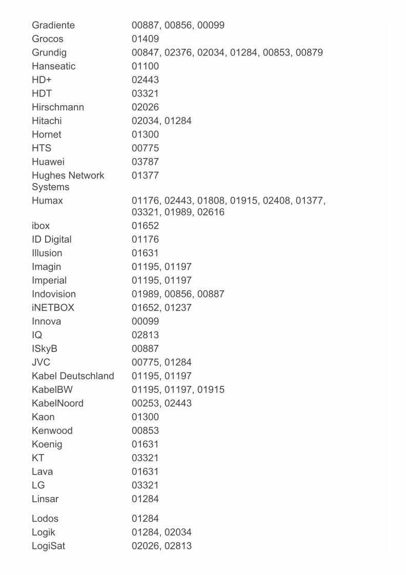
Gradiente 00887, 00856, 00099Grocos 01409Grundig 00847, 02376, 02034, 01284, 00853, 00879Hanseatic 01100HD+ 02443HDT 03321Hirschmann 02026Hitachi 02034, 01284Hornet 01300HTS 00775Huawei 03787Hughes NetworkSystems
01377
Humax 01176, 02443, 01808, 01915, 02408, 01377,03321, 01989, 02616
ibox 01652ID Digital 01176Illusion 01631Imagin 01195, 01197Imperial 01195, 01197Indovision 01989, 00856, 00887iNETBOX 01652, 01237Innova 00099IQ 02813ISkyB 00887JVC 00775, 01284Kabel Deutschland 01195, 01197KabelBW 01195, 01197, 01915KabelNoord 00253, 02443Kaon 01300Kenwood 00853Koenig 01631KT 03321Lava 01631LG 03321Linsar 01284
Lodos 01284Logik 01284, 02034LogiSat 02026, 02813

Luxor 02034Macab 00853Majestic 02738Manhattan 01300Maplin 02034Marusys 03543Mascom 02738Matsui 01284Maximum 02813Mediabox 00853MediaSat 00853Mediascape 02835Medion 02026Mega TV 03321MegaSat 02034, 02813, 01631, 02738Metronic 02738, 01631Micro 02813Micro electronic 02813MilestoneCommunications
00775
Mitsai 02738Morgan's 02026Motorola 00869, 00856, 03469Movistar 01409Multichoice 00879, 02059, 02060Murphy 02034Mysat 02738NET 01409Netsat 00099, 00887Next Level 00869Nokia 00853NPG 01631NTV Plus 01692, 02443Olleh TV 03321Olleh-Skylife 03321Onn 02034, 01284
Opticum 02957Optus 00879, 01356

Orbitech 01100, 01195, 01197Orton 02957Pace 00847, 01356, 00887, 01175, 01693, 00853,
01662, 02467, 02657, 03469, 01377, 02059,02060, 02211, 03787, 03790, 02620
Pacific 01284Palcom 01409Palsonic 02813Panasat 00879Panasonic 00847Philips 00099, 00853, 01114, 02619, 00856, 00887,
02211, 03469Pioneer 00853PLDT 02835Premiere 01114, 01195, 01197Primacom 01176, 01195, 01197Pro Basic 00853Proline 01284Qook TV 03321Qook-SkyLife 03321Qwest 01377RadioShack 00869Raduga TV 02957RiksTV 01692Roadstar 00853SAB 01300, 01631Sagem 01692, 01114Sagemcom 01692Samsung 03063, 00253, 01377, 01989, 02467, 00853,
03321, 01662, 01693, 03834Sat Control 01300SAT+ 01409Satellite Operations 00775Satplus 01100SatyCon 01631
Schaub Lorenz 02034Schwaiger 01631, 02813, 02957Schwaiger CS 01631Scott 02738
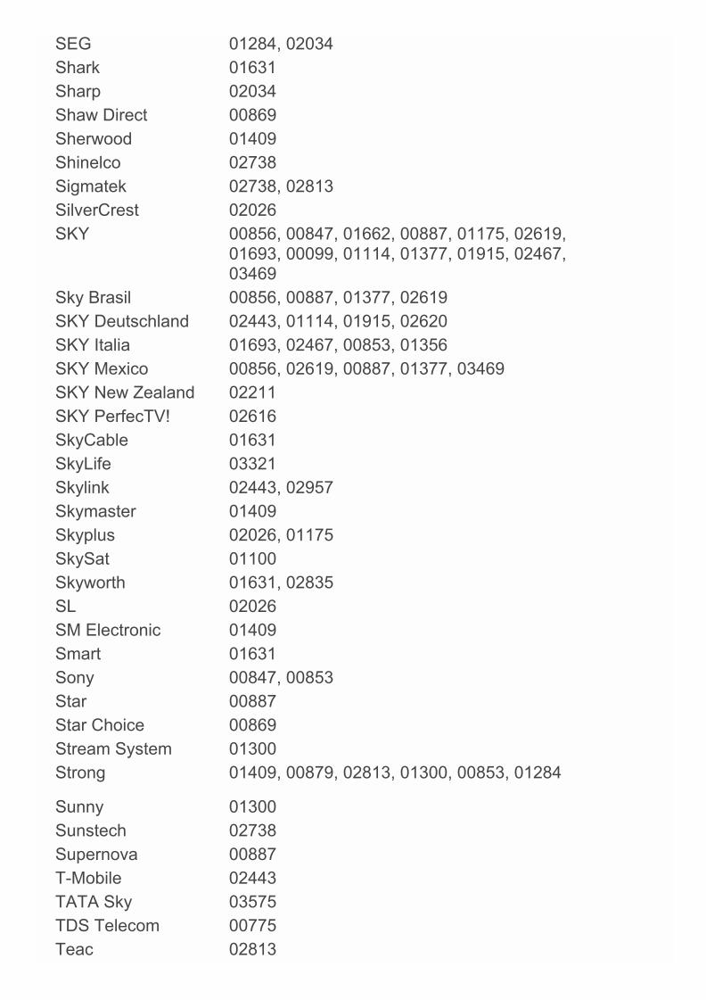
SEG 01284, 02034Shark 01631Sharp 02034Shaw Direct 00869Sherwood 01409Shinelco 02738Sigmatek 02738, 02813SilverCrest 02026SKY 00856, 00847, 01662, 00887, 01175, 02619,
01693, 00099, 01114, 01377, 01915, 02467,03469
Sky Brasil 00856, 00887, 01377, 02619SKY Deutschland 02443, 01114, 01915, 02620SKY Italia 01693, 02467, 00853, 01356SKY Mexico 00856, 02619, 00887, 01377, 03469SKY New Zealand 02211SKY PerfecTV! 02616SkyCable 01631SkyLife 03321Skylink 02443, 02957Skymaster 01409Skyplus 02026, 01175SkySat 01100Skyworth 01631, 02835SL 02026SM Electronic 01409Smart 01631Sony 00847, 00853Star 00887Star Choice 00869Stream System 01300Strong 01409, 00879, 02813, 01300, 00853, 01284
Sunny 01300Sunstech 02738Supernova 00887T-Mobile 02443TATA Sky 03575TDS Telecom 00775Teac 02813
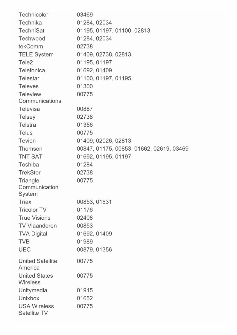
Technicolor 03469Technika 01284, 02034TechniSat 01195, 01197, 01100, 02813Techwood 01284, 02034tekComm 02738TELE System 01409, 02738, 02813Tele2 01195, 01197Telefonica 01692, 01409Telestar 01100, 01197, 01195Televes 01300TeleviewCommunications
00775
Televisa 00887Telsey 02738Telstra 01356Telus 00775Tevion 01409, 02026, 02813Thomson 00847, 01175, 00853, 01662, 02619, 03469TNT SAT 01692, 01195, 01197Toshiba 01284TrekStor 02738TriangleCommunicationSystem
00775
Triax 00853, 01631Tricolor TV 01176True Visions 02408TV Vlaanderen 00853TVA Digital 01692, 01409TVB 01989UEC 00879, 01356
United SatelliteAmerica
00775
United StatesWireless
00775
Unitymedia 01915Unixbox 01652USA WirelessSatellite TV
00775

Vectra 01195, 01197Vestel 01284, 02034Via Embratel 03787Viasat 01197, 0253, 01195VisionNet 01631Viva 00856Vivo 01409Voom 00869VTC 03834Vu+ 03543Walker 02034, 01284Wharfedale 02034Windstream 00775Wisi 02957World SatelliteCable Systems
00775
Woxter 02813, 02738Xoro 02813Xtreme 01300Yes 00887, 01631Zehnder 02034, 03469Zenith 00856, 00253Ziggo 02443Zircon 02957
Video - Accessory
A.C.Ryan 02709, 03350ABS 01272Acer 01272Alienware 01272Apple 02615Boxee 03693Claritas 01272CyberPower 01272D-Link 03693Daily Media 01272Dell 01272Digitech 02260Elonex 01272

Eminent 02260Emtec 02709Fantec 02709Fujitsu Siemens 01272Gateway 01272Hewlett Packard 01272hFX 01272Howard Computers 01272Hush 01272iBUYPOWER 01272iconBIT 02709, 03350ISTAR 02260Linksys 01272Mede8er 02709Media Center PC 01272Microsoft 01272, 01805Mind 01272NiveusMedia 01272Northgate 01272Packard Bell 01272Philips 01272PopBox 02260Popcorn Hour 02260Ricavision 01272Roku 03061Sony 02713, 01272Stack 9 01272Systemax 01272Tagar Systems 01272Toshiba 01272Touch 01272Trust 01272VIA Technologies 01272Viewsonic 01272Voodoo 01272
Western Digital 02558Woxter 02709Xbox 01805, 01272
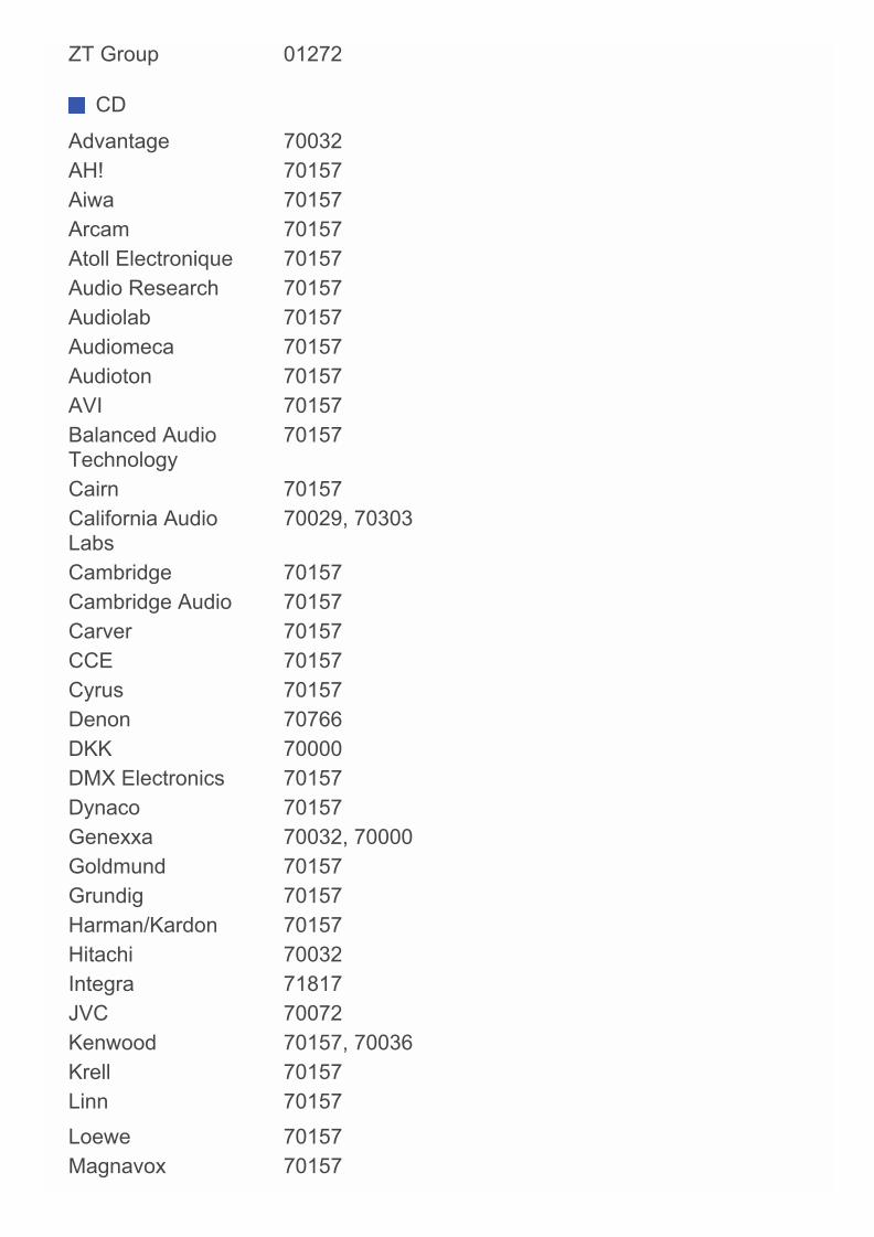
ZT Group 01272
CD
Advantage 70032AH! 70157Aiwa 70157Arcam 70157Atoll Electronique 70157Audio Research 70157Audiolab 70157Audiomeca 70157Audioton 70157AVI 70157Balanced AudioTechnology
70157
Cairn 70157California AudioLabs
70029, 70303
Cambridge 70157Cambridge Audio 70157Carver 70157CCE 70157Cyrus 70157Denon 70766DKK 70000DMX Electronics 70157Dynaco 70157Genexxa 70032, 70000Goldmund 70157Grundig 70157Harman/Kardon 70157Hitachi 70032Integra 71817JVC 70072Kenwood 70157, 70036Krell 70157Linn 70157
Loewe 70157Magnavox 70157
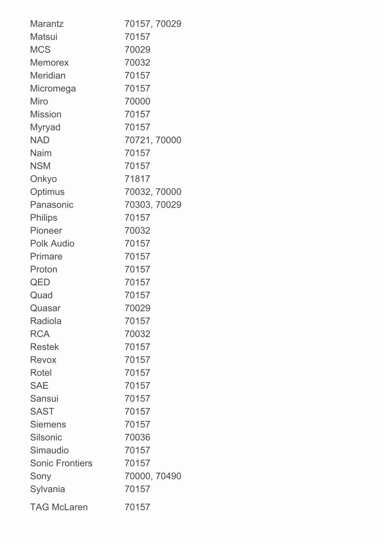
Marantz 70157, 70029Matsui 70157MCS 70029Memorex 70032Meridian 70157Micromega 70157Miro 70000Mission 70157Myryad 70157NAD 70721, 70000Naim 70157NSM 70157Onkyo 71817Optimus 70032, 70000Panasonic 70303, 70029Philips 70157Pioneer 70032Polk Audio 70157Primare 70157Proton 70157QED 70157Quad 70157Quasar 70029Radiola 70157RCA 70032Restek 70157Revox 70157Rotel 70157SAE 70157Sansui 70157SAST 70157Siemens 70157Silsonic 70036Simaudio 70157Sonic Frontiers 70157Sony 70000, 70490Sylvania 70157
TAG McLaren 70157
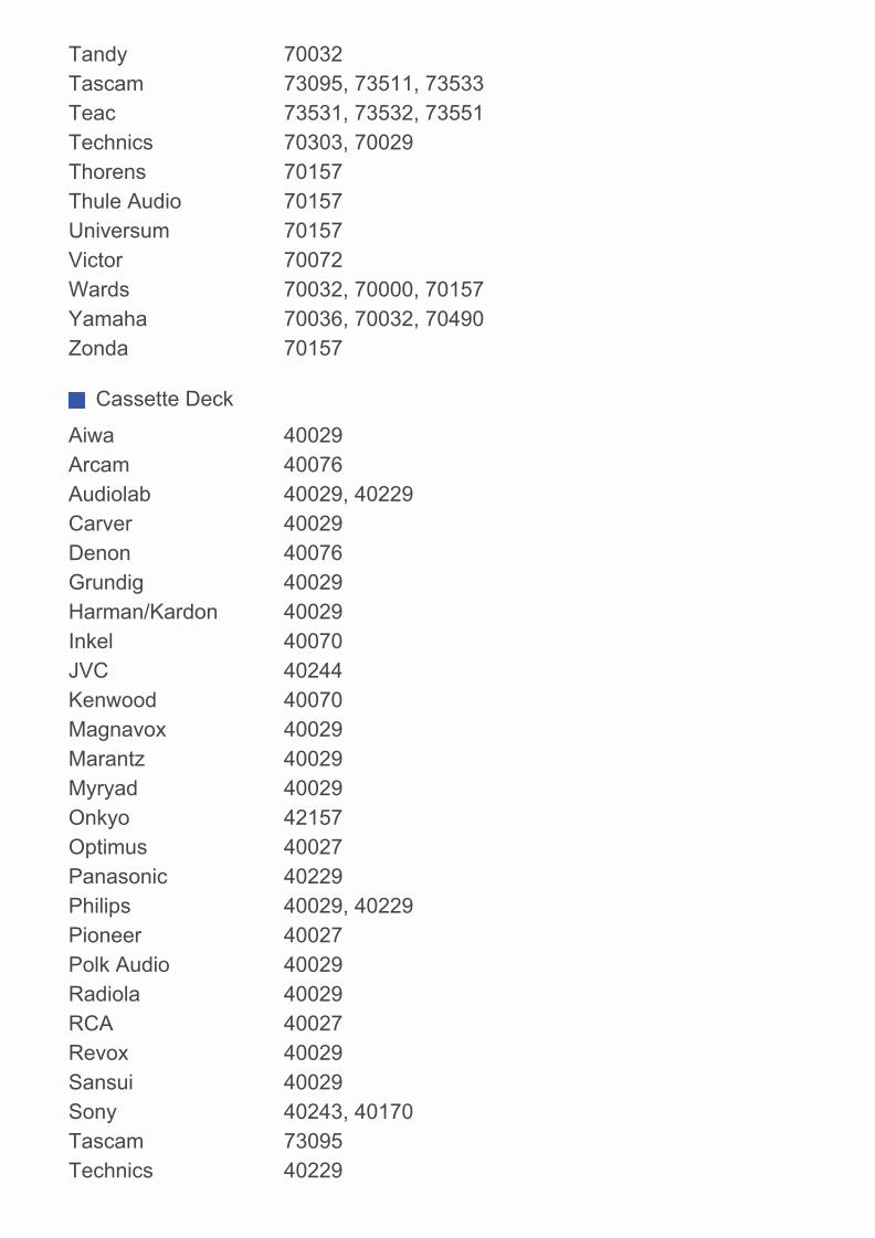
Tandy 70032Tascam 73095, 73511, 73533Teac 73531, 73532, 73551Technics 70303, 70029Thorens 70157Thule Audio 70157Universum 70157Victor 70072Wards 70032, 70000, 70157Yamaha 70036, 70032, 70490Zonda 70157
Cassette Deck
Aiwa 40029Arcam 40076Audiolab 40029, 40229Carver 40029Denon 40076Grundig 40029Harman/Kardon 40029Inkel 40070JVC 40244Kenwood 40070Magnavox 40029Marantz 40029Myryad 40029Onkyo 42157Optimus 40027Panasonic 40229Philips 40029, 40229Pioneer 40027Polk Audio 40029Radiola 40029RCA 40027Revox 40029Sansui 40029Sony 40243, 40170Tascam 73095Technics 40229
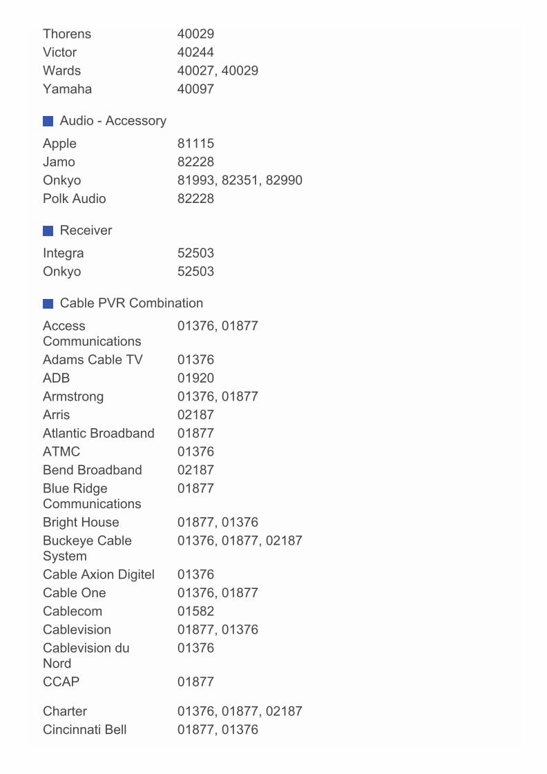
Thorens 40029Victor 40244Wards 40027, 40029Yamaha 40097
Audio - Accessory
Apple 81115Jamo 82228Onkyo 81993, 82351, 82990Polk Audio 82228
Receiver
Integra 52503Onkyo 52503
Cable PVR Combination
AccessCommunications
01376, 01877
Adams Cable TV 01376ADB 01920Armstrong 01376, 01877Arris 02187Atlantic Broadband 01877ATMC 01376Bend Broadband 02187Blue RidgeCommunications
01877
Bright House 01877, 01376Buckeye CableSystem
01376, 01877, 02187
Cable Axion Digitel 01376Cable One 01376, 01877Cablecom 01582Cablevision 01877, 01376Cablevision duNord
01376
CCAP 01877
Charter 01376, 01877, 02187Cincinnati Bell 01877, 01376
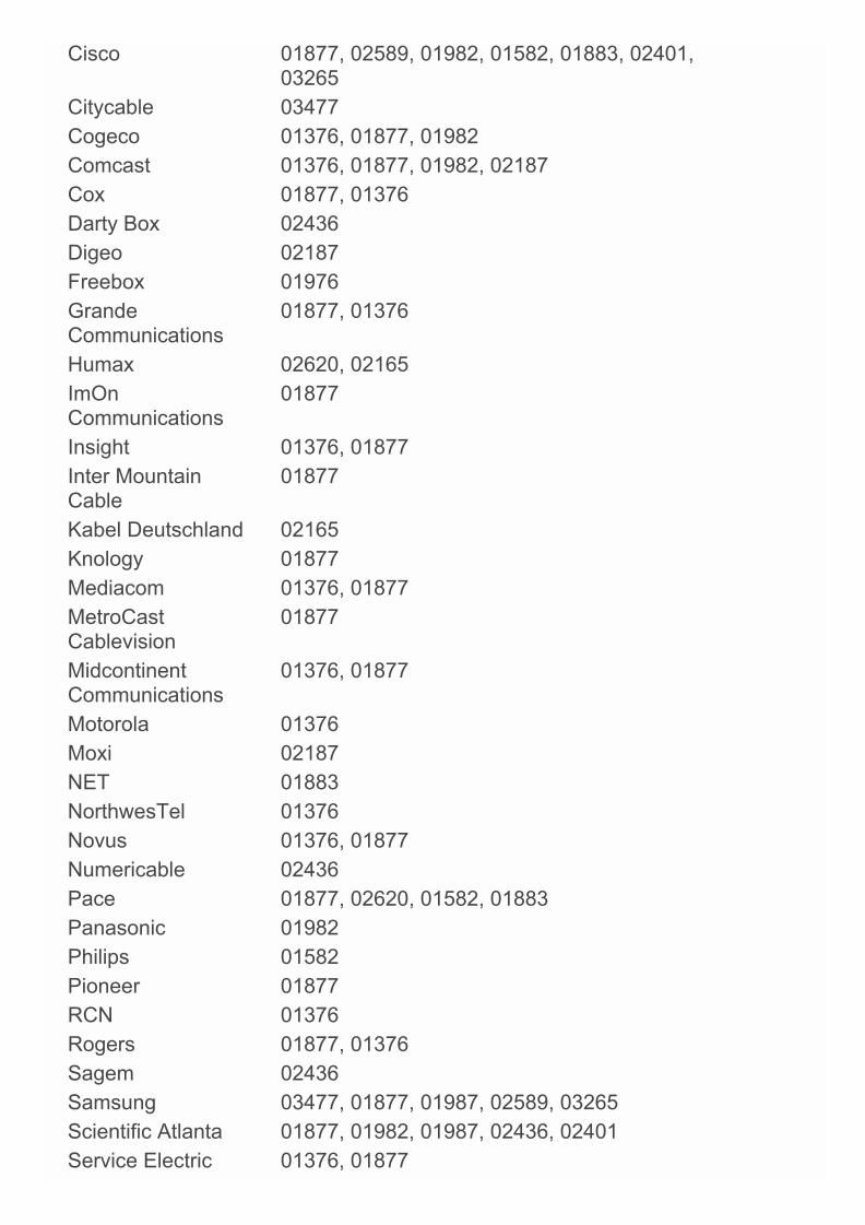
Cisco 01877, 02589, 01982, 01582, 01883, 02401,03265
Citycable 03477Cogeco 01376, 01877, 01982Comcast 01376, 01877, 01982, 02187Cox 01877, 01376Darty Box 02436Digeo 02187Freebox 01976GrandeCommunications
01877, 01376
Humax 02620, 02165ImOnCommunications
01877
Insight 01376, 01877Inter MountainCable
01877
Kabel Deutschland 02165Knology 01877Mediacom 01376, 01877MetroCastCablevision
01877
MidcontinentCommunications
01376, 01877
Motorola 01376Moxi 02187NET 01883NorthwesTel 01376Novus 01376, 01877Numericable 02436Pace 01877, 02620, 01582, 01883Panasonic 01982Philips 01582Pioneer 01877RCN 01376Rogers 01877, 01376Sagem 02436Samsung 03477, 01877, 01987, 02589, 03265Scientific Atlanta 01877, 01982, 01987, 02436, 02401Service Electric 01376, 01877
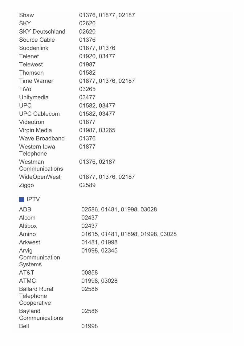
Shaw 01376, 01877, 02187SKY 02620SKY Deutschland 02620Source Cable 01376Suddenlink 01877, 01376Telenet 01920, 03477Telewest 01987Thomson 01582Time Warner 01877, 01376, 02187TiVo 03265Unitymedia 03477UPC 01582, 03477UPC Cablecom 01582, 03477Videotron 01877Virgin Media 01987, 03265Wave Broadband 01376Western IowaTelephone
01877
WestmanCommunications
01376, 02187
WideOpenWest 01877, 01376, 02187Ziggo 02589
IPTV
ADB 02586, 01481, 01998, 03028Alcom 02437Altibox 02437Amino 01615, 01481, 01898, 01998, 03028Arkwest 01481, 01998ArvigCommunicationSystems
01998, 02345
AT&T 00858ATMC 01998, 03028Ballard RuralTelephoneCooperative
02586
BaylandCommunications
02586
Bell 01998
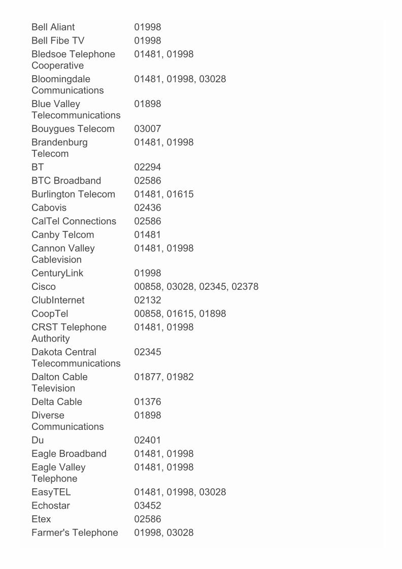
Bell Aliant 01998Bell Fibe TV 01998Bledsoe TelephoneCooperative
01481, 01998
BloomingdaleCommunications
01481, 01998, 03028
Blue ValleyTelecommunications
01898
Bouygues Telecom 03007BrandenburgTelecom
01481, 01998
BT 02294BTC Broadband 02586Burlington Telecom 01481, 01615Cabovis 02436CalTel Connections 02586Canby Telcom 01481Cannon ValleyCablevision
01481, 01998
CenturyLink 01998Cisco 00858, 03028, 02345, 02378ClubInternet 02132CoopTel 00858, 01615, 01898CRST TelephoneAuthority
01481, 01998
Dakota CentralTelecommunications
02345
Dalton CableTelevision
01877, 01982
Delta Cable 01376DiverseCommunications
01898
Du 02401Eagle Broadband 01481, 01998Eagle ValleyTelephone
01481, 01998
EasyTEL 01481, 01998, 03028Echostar 03452Etex 02586Farmer's Telephone 01998, 03028
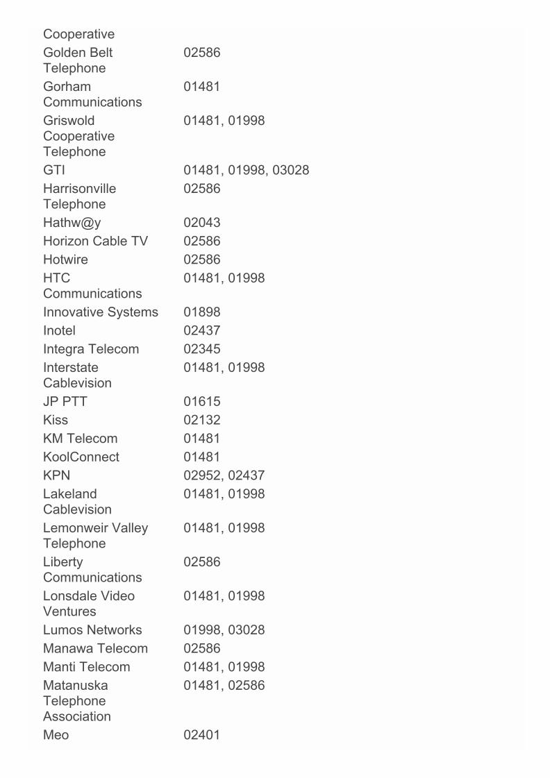
CooperativeGolden BeltTelephone
02586
GorhamCommunications
01481
GriswoldCooperativeTelephone
01481, 01998
GTI 01481, 01998, 03028HarrisonvilleTelephone
02586
Hathw@y 02043Horizon Cable TV 02586Hotwire 02586HTCCommunications
01481, 01998
Innovative Systems 01898Inotel 02437Integra Telecom 02345InterstateCablevision
01481, 01998
JP PTT 01615Kiss 02132KM Telecom 01481KoolConnect 01481KPN 02952, 02437LakelandCablevision
01481, 01998
Lemonweir ValleyTelephone
01481, 01998
LibertyCommunications
02586
Lonsdale VideoVentures
01481, 01998
Lumos Networks 01998, 03028Manawa Telecom 02586Manti Telecom 01481, 01998MatanuskaTelephoneAssociation
01481, 02586
Meo 02401

MHTC 01481, 01998
Microwave SatelliteTechnologies
01481, 01998
Millennium Telecom 01481, 01998MinburnCommunications
01481, 01998, 03028
MM&G Enterprises 01481, 01998Motorola 02378, 01998, 02437, 0858, 02952, 01376Movistar 03288MTS 01998NDTC 01481, 01998, 03028North CentralTelephone
02345
North DakotaTelephone
02586
North StateCommunications
00858
Norvado 02586Nsight 02345, 02586NU Telecom 01998, 03028Oi TV 03452, 03454Open IPTV 01615Optimus Clix 02437Orange 02407OTECCommunications
02586
Pace 02401, 03454PanoraTelecommunications
01481
Paul BunyanCommunications
02586
Pine IslandTelephone
01481, 01998
PolarCommunications
02586
Poplar BluffMunicipal Utilities
01481, 01998
Portugal Telecom 02401Price CountyTelephone
01481, 01998

Project MutualTelephone
01481, 01998
PSC 01998Quality OneTechnologies
01481, 01998
Qwerty.TV 01898RandolphTelephone
02586
Readlyn Telephone 02586ReservationTelephone
01998, 02345
River ValleyTelecommunications
01481, 01998
S-GO Video 01877Sagem 02407, 03288Sagemcom 02407Samsung 02407Sasktel 01998Scientific Atlanta 00858, 02345, 03028Silver StarCommunications
01481, 01998, 03028
SingTel 01998SKY Deutschland 02620Skyline Cable 02586SkyPix 01481, 01998Smile Content 02437Smithville 02586Sogetel 01998SureWest 01481, 01998, 02586Surry Telephone 02586SWAT Cooperative 01481, 01998, 03028T-Home 02132Telefonica 03288, 03028Telus 03028TeNeT 01898Thomson 03007, 02407TV Northeast 01481, 01998TVB 01615Twin ValleyCommunications
02586
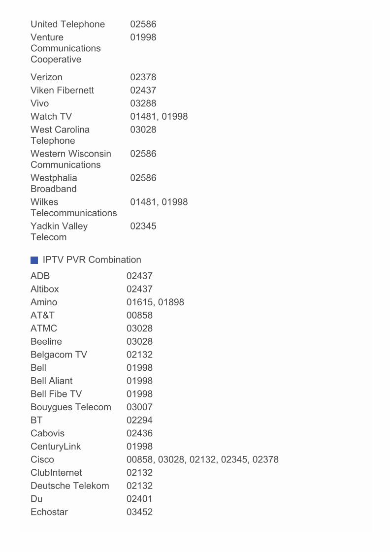
United Telephone 02586VentureCommunicationsCooperative
01998
Verizon 02378Viken Fibernett 02437Vivo 03288Watch TV 01481, 01998West CarolinaTelephone
03028
Western WisconsinCommunications
02586
WestphaliaBroadband
02586
WilkesTelecommunications
01481, 01998
Yadkin ValleyTelecom
02345
IPTV PVR Combination
ADB 02437Altibox 02437Amino 01615, 01898AT&T 00858ATMC 03028Beeline 03028Belgacom TV 02132Bell 01998Bell Aliant 01998Bell Fibe TV 01998Bouygues Telecom 03007BT 02294Cabovis 02436CenturyLink 01998Cisco 00858, 03028, 02132, 02345, 02378ClubInternet 02132Deutsche Telekom 02132Du 02401Echostar 03452
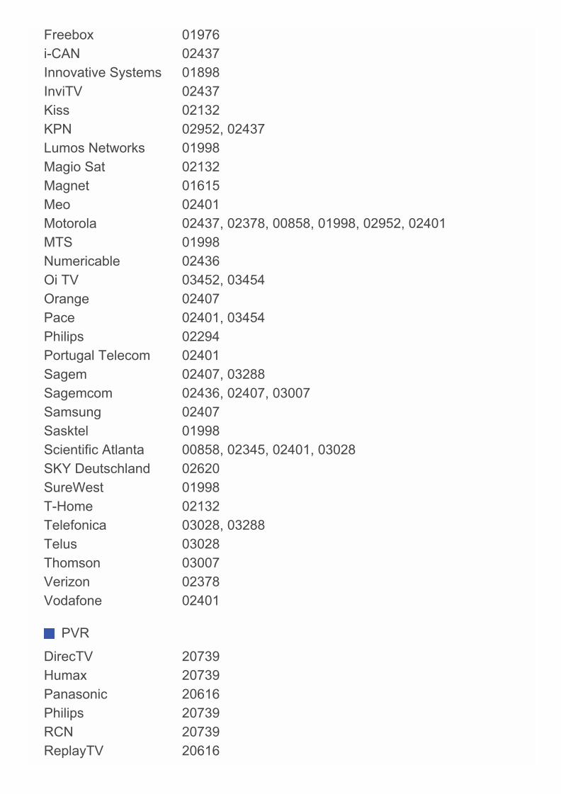
Freebox 01976i-CAN 02437Innovative Systems 01898InviTV 02437Kiss 02132KPN 02952, 02437Lumos Networks 01998Magio Sat 02132Magnet 01615Meo 02401Motorola 02437, 02378, 00858, 01998, 02952, 02401MTS 01998Numericable 02436Oi TV 03452, 03454Orange 02407Pace 02401, 03454Philips 02294Portugal Telecom 02401Sagem 02407, 03288Sagemcom 02436, 02407, 03007Samsung 02407Sasktel 01998Scientific Atlanta 00858, 02345, 02401, 03028SKY Deutschland 02620SureWest 01998T-Home 02132Telefonica 03028, 03288Telus 03028Thomson 03007Verizon 02378Vodafone 02401
PVR
DirecTV 20739Humax 20739Panasonic 20616Philips 20739RCN 20739ReplayTV 20616

Sonic Blue 20616Sony 20636TiVo 20739, 20636
SN 29401690HTML_EN(C) Copyright 2014 Onkyo Corporation Japan. All rights reserved.
Related Documents